city of los angeles - power tools, fasteners and …€¦ · the anchors have been tested in...
TRANSCRIPT

BOARD OFBUILDING AND SAFETY
COMMISSIONERS___
HELENA JUBANYPRESIDENT
VAN AMBATIELOSVICE-PRESIDENT
E. FELICIA BRANNONVICTOR H. CUEVASSEPAND SAMZADEH
___
CITY OF LOS ANGELESCALIFORNIA
ANTONIO R. VILLARAIGOSAMAYOR
DEPARTMENT OFBUILDING AND SAFETY201 NORTH FIGUEROA STREET
LOS ANGELES, CA 90012
____
ROBERT R. “BUD” OVROMGENERAL MANAGER
RAYMOND S. CHAN, C.E., S.E.EXECUTIVE OFFICER
____
RR 25700Page 1 of 3
LADBS G-5 (Rev.12/14/12) AN EQUAL EMPLOYMENT OPPORTUNITY - AFFIRMATIVE ACTION EMPLOYER
Hilti, Incorporated RESEARCH REPORT: RR 257005400 South 122nd East Avenue (CSI # 13 16 00)Tulsa, Oklahoma 74146
BASED UPON ICC EVALUATION SERVICEAttn: Chris Gamache ES REPORT NO. ESR-2322(918) 872-3169
REEVALUATION DUEDATE: May 1, 2015Issued Date: April 1, 2013Code: 2011 LABC
GENERAL APPROVAL – Reevaluation - Hilti HIT-RE 500-SD Adhesive Anchors inConcrete.
DETAILS
The above assemblies and/or products are approved when in compliance with the description, use, identification and findings of Report No. ESR-2322, reissued February 1, 2012, revisedMarch 2013, of the ICC Evaluation Service, Incorporated. The report, in its entirety, is attached and made part of this general approval.
The parts of Report No. ESR-2322 which are marked by the asterisks are deleted or revised by the Los Angeles City Building Department from this approval.
The approval is subject to the following conditions:
1. The design information listed in the attached report and tables are valid for the fasteners only. Connected members shall be checked for their capacity (which may govern).
2. The anchors shall be identified by labels on the packaging indicating the manufacturer’s name and product designation.
3. Design information, edge distance, spacing and minimum embedment requirements shall be per Tables in ICC-ES Report No. ESR-2322.

Hilti, IncorporatedRE: Hilti HIT-RE 500-SD Adhesive Anchors In Concrete.
RR 25700Page 2 of 3
4. The design information in the tables for temperature range B shall be used as specified in ICC-ES Report No. ESR-2322 when the anchors are installed in locations where the long term concrete temperature exceeds 80 �F.
5. Special inspection in accordance with Section 1704 of the 2011 Los Angeles City Building Code shall be provided for anchor installations.
6. The anchors shall be installed as per the attached manufacturer’s instructions except as otherwise stated in this report. Copies of the installation instructions shall be available at each job site.
7. The adhesive anchors shall not be used to support fire-resistive construction.
8. The anchors are not approved for unreinforced masonry walls.
DISCUSSION
The report is in compliance with 2011 Los Angeles Building Code.
This approval is based on load tests. The anchors have been tested in accordance with ASTM E488 and the ICC-ES Acceptance Criteria for Post-installed Adhesive Anchors in Concrete (AC308), dated October 2007. Creep tests were carried out in accordance with the ICC-ES Acceptance Criteria for Post-installed Adhesive Anchors in Concrete (AC308), dated October 2007.
This general approval will remain effective provided the Evaluation Report is maintained valid and unrevised with the issuing organization. Any revision to the report must be submitted to thisDepartment for review with appropriate fee to continue the approval of the revised report.
Addressee to whom this Research Report is issued is responsible for providing copies of it,complete with any attachments indicated, to architects, engineers and builders using itemsapproved herein in design or construction which must be approved by Department of Building and Safety Engineers and Inspectors.
This general approval of an equivalent alternate to the Code is only valid where an engineer and/or inspector of this Department has determined that all conditions of this Approval have been met in the project in which it is to be used.

Hilti, IncorporatedRE: Hilti HIT-RE 500-SD Adhesive Anchors In Concrete.
RR 25700Page 3 of 3
Hilti offers software to assist in the design of anchorages using Hilti products. The software Hilti PROFIS Anchor includes selectable Strength Design methodology utilizing ICC-ES AC308-compliant data to generate designs in conformance with the 2011 Los Angeles City Building Code. Printed Strength Design aids are also available for this product.
____________________________________ALLEN PEERY, ChiefEngineering Research Section201 N. Figueroa St., Room 880Los Angeles, CA 90012Phone- 213-202-9812Fax- 213-202-9943
KHRR25700/MSWord2010R03/29/135A1/1912, ACI 318-08 appendix D
Attachment: ICC ES Report No. ESR-2322 (44 Pages)

ICC-ES Evaluation Reports are not to be construed as representing aesthetics or any other attributes not specifically addressed, nor are they to be construed as an endorsement of the subject of the report or a recommendation for its use. There is no warranty by ICC Evaluation Service, LLC, express or implied, as to any finding or other matter in this report, or as to any product covered by the report.����������� ���� Page 1 of 44
�����
ICC-ES Evaluation Report� ESR-2322*�������������� ���������
� ������������������������������������������������
www.icc-es.org | (800) 423-6587 | (562) 699-0543 ���������� �� �����!�������������"����"�������#�
DIVISION: 03 00 00—CONCRETE Section: 03 16 00—Concrete Anchors
DIVISION: 05 00 00—METALS Section: 05 05 19—Post-Installed Concrete Anchors
REPORT HOLDER:
HILTI, INC. 5400 SOUTH 122ND EAST AVENUE TULSA, OKLAHOMA 74146 (800) 879-8000 [email protected]
EVALUATION SUBJECT:
HILTI HIT-RE 500-SD ADHESIVE ANCHORS IN CONCRETE
1.0 EVALUATION SCOPE
Compliance with the following codes:
�� ����� ����� ���� ���� ���� !������������� $������%�"�����������
�� ����� ����� ���� ���� ���� !������������� ������������"�����������
Property evaluated:
��������� �
2.0 USES
!"� #� ��� #�!$�%� &��$�'� (�")�*"� (������� ��)�"+� �)��)"�� ��� �")�)�� )������� ,���� ���� )"�)+��� �"�)���� ���� )"��� ���)� ��� ����-"�� ���� ������-"�� ���+� $,"��� �����"�"��*�����)�"��.�"����+��"))�*"�)��"����.�����.� �&����)�����/�&��� �)�� ��01 � 23�� ��� &/1�� 23��1� !"� ������ )�)�"+� �)���� � �"�����*"� ��� ��)�$��$� ��"� ���� ��)�$��)�� "�� �����)��")���4"������"�����)������������� ��.��"� �������� �������������"�����)���� �����������.��"� ������� �������1�!"� ������ )�)�"+)� +��� � )�� 4"� �)"�� ,"�"� ���"���""�"���")����)�)�4+���"��������������"�,����"����������1�1�� �.� �"� ����� ���� ���� ���� ����� �"����������1�1���.��"� �������������"����������1�1 ��.��"� �������1�
3.0 DESCRIPTION
3.1 General:
!"� #� ��� #�!$�%� &��$�'� (�")�*"� (������� ��)�"+� �)���+���)"���.��"�.� �,�����+���"��)5�
•� #� ���#�!$�%�&��$�'���")�*"����-�"�����.�� ����-)�
•� (�")�*"�+�6���������)�"�)���"7���+"���
•� %7���+"���.���� "�� "�����������")�*"���8"������
!"� #� ��� #�!$�%� &��$�'� (�")�*"� (������� ��)�"+�+���4"��)"��,������������) ����"��"�������#� ���#��$���9����� #��$�9� ���"��� �� ��"��"�� ��)"��)� ��� �".��+"�� )�"" ��"��.������ 4��)1� !"� ���+���� ��+���"��)� �.� �"� #� ���(�")�*"� (������� ��)�"+�� ��� ����� �"� #� ��� #�!$�%�&��$�'�(�")�*"��#�!$�%$2�)������+�6�����:: "�����)�"" ���������" "+"��)����"�)�,�����;���"� ��.���)��"����1�
��)�� ��������.��+��������������+"�"�)���)���� ��"��,���"�����")�*"���������-�"����"��"� ����"���)�;���"�&��.���)��"����1�
3.2 Materials:
3.2.1 Hilti HIT-RE 500-SD Adhesive: #� ��� #�!$�%� &��$�'� (�")�*"� �)� ��� ��8"���4 "� �,�$��+���"��� "��6����")�*"1�!"��,����+���"��)���"�)"�����"��4��+"��)��.��� ��� $�� ���"�� .�� � ���-� �����"�� ��� �� +���.� �1� !"� �,����+���"��)���+4��"������"����,"����)�"�)"���������)������+�6�����:: "������"�� ����"�+���.� �1�#� ���#�!$�%�&��$�'� �)� �*�� �4 "� ��� ��1�$����"� ����� + ��� ��1�$����"��&��� + ��� ���� <01�$����"� ��<��� + �� .�� � ���-)1� !"�+���.� �� �����"�� ��� "��� .�� � ���-� �)� )��+�"�� ,��� �"���")�*"�"6������������"1�!"�)" .� �."���)��������"��4���"�"6��������� ���"�� ����")����)� ��� ��� ����"�"�� .�� � ���-�)���"���������������-�"�*����+"��1�
3.2.2 Hole Cleaning Equipment:� #� "� � "�����"7���+"��� +�)�� 4"� ��� ���������"� ,��� ;���"� &� �.� ��)��"����1�
3.2.3 Dispensers:� #� ��� #�!$�%� &��$�'� +�)�� 4"���)�"�)"��,���+���� ���)�"�)"�)����"�+�������)�"�)"�)�����" "��������)�"�)"�)����*��"��4��#� ��1�
3.2.4 Anchor Elements:
3.2.4.1 Threaded Steel Rods:�!�"��"��)�"" ����)�+�)��4"� � "���� ���������) �� ��"��"�� ���)� �� $��"���� ������+"�"�)��)��")���4"�����!�4 ")�0������������;���"�&��.���)��"����1���"" ��")�����.��+������.�����++������")��.���"��"�����)���"����*��"�����!�4 "� �����!�4 "��1����4���)�"" � ��"��"�� ���)� +�)�� 4"� .����)"�� ,��� �� �1��&$+� �+"�"�$���-��&�=+��:����" "����� ��"�����������+� ����,���(�!2���������������+�)��4"���$����"��� *���:"����+� ����,���(�!2�(��&���� �))������'1�!�"��"��)�"" ����)� +�)�� 4"� )������ ���� .�""� �.� ���"�������)� ��� ��"���"."��)�� ����"��� "��1�!"�"��)�+���4"�)��+�"��,�����"���.����+��-)������"�"+4"��"��"���+���4"�4 �������������������"�4��)����)" �������1�
*Revised March 2013
*
*
*
*
Deleted by the City of Los Angeles*

ESR-2322 | &����'���� ��������������������� Page 2 of 44 �
3.2.4.2 Steel Reinforcing Bars:� ��"" � �"��.������ 4��)���"� �".��+"�� 4��)� ��"4���1� !�4 ")� ��� 0� ���� ��� ����;���"�&�)�++���:"��"��.������4���)�:"����")1��""�!�4 "��� .��� )�"��.�������)� �.� ��++��� �"��.������ 4��� ���")� �������")1� !"� "+4"��"�� �������)� �.� �"��.������ 4��)� +�)��4"�)����������� .�""��.�+� �)�� "�� ��)������ ��"��������)����� +��� �+����� �"� 4���� ,��� �"� ��")�*"1� �"��.������4��)�+�)������4"�4"����.�"����)�� �������"6�"����)�)"��.������� �"������ 01�1 � �.� (��� ��/� ,��� �"� ��������� � ���������������"�4��)�+�)��4"�4"����� �������"������.��"��.������4��)����.��� ����"�.�" ��4"������)������"�+���"�1�
3.2.4.3 HIS-N and HIS-RN Inserts: #� ���#��$9�����#��$�9� ��)"��)� �*"� �� ���.� "� ��� �"� "6�"��� � )��.��"� ���� ��"����"��� �� ��"��"�1� 2"������ � ����"���")� .��� #��$9� ����#��$�9� ��)"��)� ��"� ���*��"�� ��� !�4 "� <1� !"� ��)"��)� ��"��*�� �4 "� ������+"�"�)����� "��)��)�)�,�����!�4 ")��&����� ��� ���� ;���"� &1� #��$9� ��)"��)� ��"� ������"�� .��+����4��� )�"" � ���� .����)"�� "��"�� ,��� �� �1��&$+� �+"�"�$���-� �&� =+�� :���� " "����� ��"�� ������� ��+� ���� ,���(�!2� �� ���� ��� �� ��� �� ��$����"�� � *���:"�� ���������+� ���� ,���(�!2�(��&���� �))������'1�!"�)���� "))�)�"" � #��$�9� ��)"��)� ��"� .�4�����"�� .��+� >&��9�2��0� �?0��� )�"" � ���.��+��� ��� '�9� �0<<�1� ��"��.�������)� .�����++��� 4� �� ���")� ���� +��� 4"� �)"�� ��� ���8�������� ,���#��$9� ���� #��$�9� ��)"��)� ��"� ���*��"�� ��� !�4 "� &1� �� �����"� ���� +��"��� � ���"� ����4���� )���� "))�� +�)�� 4"�+���"�� ��� �"� ��)"��1� ���"��� �"�������� .�����)�� @������")������� ��� 4���� "� )�"" � " "+"��)� +�)�� 4"� �)"�� .���#��$9�����#��$�9���)"��)1�
3.2.4.4 Ductility:� ��� ���������"� ,��� (��� ��/� (��"���6�'��������"��.�����)�"" �" "+"������4"����)��"�"������� "���"��")�"�� " �������� +�)�� 4"� ��� "�)�� �<� �"��"��� �����"�������� �.� ��"�� +�)�� 4"� ��� "�)�� ��� �"��"��1� ��"" �" "+"��)�,������")�"��" �������� "))������<��"��"���������"�������� �.� ��"�� "))� ���� ��� �"��"���� ��� 4���� ��"����)��"�"�� 4���� "1� A� �")� .��� *�����)� ��++��� )�"" �+��"��� )���"����*��"�����!�4 ")� ��������&��.���)��"����1�
3.3 Concrete:
9��+� $,"��� �����"�"� +�)�� ��+� �� ,��� �"������ ��������� ���&� �.� �"� ���1� !"� )�"��.�"�� ��+��"))�*"� )��"����.������"�"�+�)��4"�.��+� �&����)�����/�&����)����01 �23�����&/1��23��1�
4.0 DESIGN AND INSTALLATION
4.1 Strength Design:
4.1.1 General:� (����� �")��� )��"��)�� �(�� ���� �)���+�)��4"��"�"�+��"��������������"�,���(�����/$�/�� ��������� ��� (��� ��/$�&� (��"���6� '� ���� ��)� �"����1� (� �")���"6�+� "� �)� �*"�� ��� ;���"� <� �.� ��)� �"����1� '")�������+"�"�)� ��"� ���*��"�� ��� !�4 ")� &� ����� ��� �.� ��)��"����1� '")��� )��"��)� +�)�� 4"� �"�"�+��"�� ������������"�,���(�����/$�/���)����� �"�����*"�����"� �������� ���� ����� ���� �"������ ����1�� �.� �"� ���1� '")�������+"�"�)� ��"� 4�)"�� ��� �"� ���� ���� �(��� ��/$�/���� "))����"����"�,�)"�����"�����)�'1<1�1�������<1�1����.� ��)� �"����1� !"� ������ �")��� +�)�� )���).�� �"��"7���"+"��)� �.� (��� ��/� �"�����)� '1<1�1�� ���� '1<1�1 1����"����"��������.�����)������")���4"�����(�����/��"������'1<1<���������"�����!�4 ")�&����������.���)��"������+�)��4"� �)"�� .��� ���� ��+4�������)� �� �� ��"�� ��� ���������"�,����"���������&1 1���.��"���������(�����/��"�������1 1����"��� �"�������)� .�����)�� ��� �")���4"�� ��� (��� ��/��"������ '1<1&� +�)�� 4"� �)"�� .��� ���� ��+4�������)��� �� ��"��������������"�,���(��"���6����.�(�����/1�
!�)�)"���������*��")��+"��+"��)����(�����/�(��"���6�'��)��"7���"��.����"�)��"����")����.���")�*"������)1�������.��+���"�,���(�����/��� �"7������)���"�"6��"))"��
������$����������)1�
2���.��(�����/�'1<1�1 ��)�.� �,)5�
*������+!�� ,-�� .*/�0� ���� .*/�0�� �(�� ���� �)�� ���� ����������� ����%�� �����%���� �����1����� ��1� ���� ������������ ������� 1������� �(�� ��� ���� ������� ����%�� �����%��� ����������� � � ��� ������� ��� %����� � � �������� ��� �����1����� ��1���������������� ��(������������(������(�%��������������(������(�%���)��������������������%�������%������������� ���� ������� ��� �� %����� � � �������� ��� �����1����� ��1���������������� ��)������������)������)�%��������������)�������)��%�����������2������������������������������������%� ��1� ���������� ������%�� �� ��� ��� *������� ��� �������������-����1������
(���(�����/�'1<1�1 ��)�.� �,)5�
*������+� ��� ������2�� �������� ��������� ��� ����������������%� ��1� ���������� ������%�� �� ������1����� � ����%������ ��������������� ��1�������%�,-��.*/�0������ �(�����������1����� ��1� ���� ���������� ����� ������� ��%��� ���� ���������� ���� ����� �������� � � ���� ��2�� ����� �����%� ����� 1� � �������������������������������(����������1�������� ������3�
*��������+������%����������3��(��4���56�(����
*��������+��� ������� %������� ,-������� .*/�0� ������ ������� ���� � ��7��%� �(�� 4� ��56�(��� ��� ����� ������� ��� ����������%������������������������%�������������������
*�������8+'����� ������ ������ ���� ����������� � ����� �������������� �������� ������ ������������ � � �������� ���� ������������ �� ���� 9��� ��� ����������� ����� �"!� 8�:� ��������*�����8��
4.1.2 Static Steel Strength in Tension:� !"� ��+��� �)��"����.��������������"�)�����)��*"��"��4���"�)�"" ��9)��� ��� ���������"� ,��� (��� ��/� �"������ '1&1�1 � ����)��"��� �"�������� .�����)� ��� ���������"� ,��� (��� ��/��"������'1<1<���"��*"������"���4 ")���� ��"�����!�4 "���.����"�����")�������������)�"" 1�
4.1.3 Static Concrete Breakout Strength in Tension:�!"���+��� ������"�"�4�"�-����)��"��� ��� �"�)�����9�4����9�4��+�)��4"��� �� ��"��������������"�,���(�����/�'1&1 �,����"�.� �,�����������5�
*�6���;+.���<� !$"0� ��� *�6������ .���;� !$"0� =� ������1����%� ��������� �����%��� � � ������2�� �������� ��� �������������� �� ����������� ��� ����������� ����*�6����� ��� *�6���;������� �������;� !$"����*�6����� ���*�6���:������� �������<�!$"�����������2������ �7���������������,-��.*/50��������3�
7������ 4� �5� ������ ���� ���� ���������� ����7��%� ������2���� ����� ��2���� ��� ���� ������� 2������ �.����7�����������0�
7������� 4� ��� ������ ���� ���� ���������� ��� ����7��%� ������2���� ����� ��2���� ��� ���� ������� 2������ �.������7�����������0�
(�������� � ��.��+������ .��� �"� �"�"�+�������� �.� �"���+��� ������"�"�4�"�-����)��"����9�4����9�4���)��*"������"���4 ")���� ��"�����!�4 "���.����"�����")�������������)�"" 1� !"� *� �"� �.� ��� +�)�� 4"� �+��"�� ��� �� +�6�+�+� �.�/����� �)�� �&&� 23��� ��� ���������"� ,��� (��� ��/� �"������'1�1&1�
4.1.4 Static Pullout Strength in Tension:� ��� �"�� �.��"�"�+����� �"� ��+��� � �� ���� )��"��� ��� ���������"�,���(�����/�'1&1�����+��� �4����)��"�������"�)����+�)��4"� �� �� ��"�� ��� ���������"� ,��� �"� .� �,��� )"�����)����"�����(�����/5�
*�6�8�5+���� ��1����� ���� �����%��� � � ��� ������2��
*
Deleted by the City of Los Angeles*

ESR-2322 | &����'���� ��������������������� Page 3 of 44 �
��������(������%������ �������2�����������(�%�� ��� �������������������>�����
.�0� ��������%����������
(�4 �(��(��
�?���(��?��(��(��� .*/�<�0�
�.0� �����%������ ���������
(��4 �(��(��
�?���(��?%�(��?���(��?��(��(��� .*/�<0�
,"�"5�
���� ��� ���� ���������� ����� � � ���� ������� ��� ���� ��� �������%��� ������� ��� %����� � � �������� ����� ������ �������>�1����� ��� ���� ���� � � ���� ������������ %��1�������� �%���� ����� �������� ��1� ���������%� ���� ������� ��� ���������������������������(�� ��1������������������ ��������%����������� ��� ��� ���� ������ � �� %������ � ��������� ��1� �� ����������%�� �� ���� � � ��������� ��������� ���� ������ ���� �>������������������� ��� ������1���� � �������� ��� �������� ��� ����%������ !�� �"!� 8�:� �%����� �*�6������ ���� �*�6������ �������1�� ��6�� � ���� 8���� � ������ �� ��������� ����� ����(�� ��������(�����������2�� ��
�(��� ��� ���� ���������� ����� � � ���� ������� ��� ���� � � �����%������������������ ���� �� �������� ����>�1������%��� �������������������,-��.*/�<�03�
����� 4� .����(�0��� .*/�<�0�
,���
����(�� 4� ���%�2��� �,-��.*/�<�0�
*�6�8�:+���� ��������� ������%� ����(�� ���� ��������� ��%���������������(������������������������ ������3�
����(�� 4� �B�B��7�������<&�
C�8�� �� .*/�<�0�
����(��� 4� ������(�
�� .*/�<�0�
*�6�8�;+��������������%���� ������%���������2���������������������������7�����������������������>�����
(��4�7�����@������� ��� .*/�< 0�
,"�"�
�7�����������������������������������%����������7�������������
*�6�8���+����1��� �������� ������ ��������� �������� ����� ���������� ����� ���%������ �������2�������������
?%�(�4?%�(��A �����(�
���6 � ��/?%�(�� �� �'$����
,"�"5�
?%�(�4��/ ���/��� �7����7�1�>���
���6�B���� �'$����
,"�"5��� 4� ���� ��1��� � � �������/������� ������2��
�������������%������
�7�1�>���47����@�� ��� � C�� �'$�����
����2������ � D��1��������1��������1�>�1�1�� �:���������.66� &E�0� ��� ����������� ����� �"!� 8�:� �������� *�8�6�
*�6�8���+���� 1��� �������� ������ ��� ������������ � �������������2���������%���������
?���(�4 �
�A��C(
����(�
F���� �'$��8��
,-��.*/�<�0����2����� ���e'N s2���
! � ���� ������%� ��� ��� ������� %����� ��� ����� ����� ��� ������������������������������������ ��������������������������� �������� ������ �� ����������� ����� �����1����%� ��������������� ���G(�� ����������,-��.*/�<�0��
!�� ���� ����� ������ ���������� ������%� �>����� ����� ���������%����� �>���� ���� 1��� �������� ������ H���(�� ������ ����1������ ��� ����� �>��� ����2������ � ���� ���� �������� � ������� ���������������H���(�����,-��.*/�<0��
*�6�8���+����1��� �������� ������ ���������%��� ����� ������%��� ������2�� �������� ��� ������� %������ ������� �������������3�
H���(��4����� ������1���B�����(�� �'$�� ��
���
?���(�4 ��5A��8� ���1������(�
� F����,"����1���I�����(�� �'$��+��
*�6�8��8+'���� ��� ������2�� ������� ��� �� %����� � �������2�� �������� ��� �������� ��� �� ��%���� � � �� ���������1�1��� ������ ���� ���� ���������� ��� ����7��%� ��� ���2��������� ��2����� ���� ��1����� �����%���� (�� ��� (�%�� � � �� ���%���������2��������������%������ �������2����������������������������� ��������%� ���,-�� .*/�<�0�����,-�� .*/�<0�������7���� ����������� ��� �7���� ��� ���� ������������ � � ���� ����������%��� (��� ��� ����������� ����� ,-�� .*/�< 0�� ���� ������D�9��� ������ �� ����������� ��� ����������������,-�� .*/�<�0������ � ���� 2����� � � �7�1�>������ ������ �� ����������� �������������������,-��.*/�<�0���������������� ����7�1�>��������,-��.*/�<�0��
�7�1�>�����47������
@�� ��� � C�� �'$�����
*�6�8���+'���� ��� ������2�� ������� ��� �� %����� � �������2�� �������� ��� �������� ��� �� ��%���� � � �� ���������1�1��� ������ ���� ���� ���������� ��� ����7��%� ��� ���2�����������2���������1��� �������� ������D��9������������7������
?��(�E��1��,"�����1���≥����� �'$�����
?��(�4 ����1��J�����(�
�����,"�����1���I����� �'$������
������ ���� 1���� �� �����1����� ��� ����������� ��������������������� ���������������
������������������3�?��(��4�����
(�������� � ��.��+������ .��� �"� �"�"�+�������� �.� ��+��� �4����)��"�������"�)�����)��*"������"������<1�1/1�
4.1.5 Static Steel Strength in Shear:�!"���+��� �)������)��"��� �.� ��� ������ ��� )"��� �)� �*"��"�� 4�� �"� )�"" ��)���� ��� ���������"� ,��� (��� ��/� �"������ '1�1�1 � ����)��"����"��������.�����)���"��*"������"���4 ")���� ��"�����!�4 "���.����"�����")�������������)�"" 1�
4.1.6 Static Concrete Breakout Strength in Shear:�!"���+��� � �����"�"� 4�"�-���� )��"��� �.� �� )�� "� ������ ���������.������)����)"����)�����)�%��+�)��4"��� �� ��"����� ���������"� ,��� (��� ��/� �"������ '1�1 � 4�)"�� �����.��+������ �*"�� ��� �"� ��4 ")� ��� ��"�� ��� !�4 "� �� .��� �"�����")������� ������ )�"" 1� !"� 4�)��� �����"�"� 4�"�-����)��"����.���)�� "����������)"����A4��+�)��4"��� �� ��"��

ESR-2322 | &����'���� ��������������������� Page 4 of 44 �
��� ���������"� ,��� (��� ��/� �"������ '1�1 1 � �)��� �"�*� �")��.��������� ��*"������"���4 ")��)���� ��"�����!�4 "��� .��� �"� ����")������� ������ )�"" � ��� �"�� �.� ��� ���� K����")�"���*" �1���������)"�+�)���� �"6�""��:��1�!"�*� �"��.� ���+�)��4"� �+��"�������+�6�+�+��.�/������)���&&�23���������������"�,���(�����/��"������'1�1&1�4.1.7 Static Concrete Pryout Strength in Shear:���� �"���.� �"�"�+����� �"� ��+��� � ������� )��"��� ��� ���������"�,��� (��� ��/� �"������ '1�1�1��� ��+��� � ������� )��"��� ���)"���+�)��4"��� �� ��"��������������"�,����"�.� �,���)"�����)����"�����(�����/5�
*�<�8��+���� ��1����� �� ���� �����%��� � � �� ���%���������2�� ������� )��� ��� %����� � � ������2�� �������� )��%������������>����3�
.�0� ��������%���������2��������3�
� )���E�1����7���⋅�(�F�7���⋅�(������ .*/8��0�.0� �����%������ �������2���������3�
� )��%�E�1����7���⋅�(�%F�7���⋅�(�%���� .*/8�0�,"�"5�
7��� 4� ���� ����� �<���6�����.<��110�
7��� 4� ���� ����� �≥���6�����.<��110�(����������������������������������������,-��.*/�<�0�(�%���������������������������������������,-��.*/�<0�(��(�%� ���� �����1����� ��� ����������� ����� *�6����� ���*�6���;��
4.1.8 Bond Strength Determination:� ����� )��"���*� �")� ��"� �� .�������� �.� �����"�"� ���������� �����-"���������-"���� ��� ��� +"���� ��++"�� ��� �� ���"� ��� �� ������)�� ������ ���������)� ������ ,��"�$)������"��� "��1�1� �����)��"��� *� �")� +�)�� 4"� +���.�"�� ,��� �"� .������ L��� .�����)")� ,"�"� � ")� ��"� ��� "�� ��� ,��"�$)������"�� �����"�"��L�����,"�"��"�� ")���"�,��"�$.� "������"���+"��.���������)�� ������ �L� ��� ��� ,"�"� �"� ������ ��)�� ������ �)��������"�����"�,��"���L�����)�.� �,)5�
CONCRETE
TYPES�
CRACKED�
HOLE
DRILLING
METHOD�
PERMISSIBLE INSTALLATION CONDITIONS�
BOND STRENGTH�
ASSOCIATED STRENGTH REDUCTION
FACTOR�
'��������"�"� �7���� φ��
G��"�$)������"�� �7����B�M��� φ���
UNCRACKED�
'��������"�"� �7������ φ��
G��"�$)������"�� �7������B�M��� φ���
G��"�$.� "��� "� �7������B�M� � φ� �H��"�,��"����� �������� �7������B�M��� φ���
'��������"�"� �7������ φ��
G��"��)������"�� �7������B�M��� φ���
;���"� �� ��")"��)� �� )" "������ . �,����1� G"�"���� ���4 "�� �"� +���.�"�� 4���� )��"��� *� �")� +�)�� 4"��)"����� �"���.��7���������7���������%7������)��'$�������'$��.����'$���� ���� �'$��8�1� !"� �")� ���� ��+��� � 4���� )��"���+�)�� 4"� +� ��� �"�� 4�� �"� �))�����"�� )��"��� �"��������.������φ��1�
4.1.9 Minimum Member Thickness hmin, Anchor Spacing smin and Edge Eistance cmin:���� �"���.�(�����/��"������ '1/1��� *� �")� �.� �1��� ���� �1��� �")���4"�� ��� ��)��"�����+�)��4"��4)"�*"��.����������")���������)�� �����1�
I�-",�)"�� ��� �"�� �.� (��� ��/� �"������ '1/1&�� �"� +���+�+�+"+4"�����-�"))")���1�����")���4"�������)��"�����+�)��4"��4)"�*"��.����������")���������)�� �����1�����"�"�+�����+���+�+�"�"���)����"���1�����"�.� �,���)"������+�)��4"����"�����(�����/5�
*�:�:+���������2����������������������1���������-��������� 1���1�1� ��%�� ��������� ������ �� ����� ��� 1���1�1���2��� ��-����1����� ��� ���� ����1���� ��� �������� 5�5�� ���������2���������� ������������ ���-����� ����1���1�1���%����������� ���� ������%� ������ �� ��7��� ��� <��� ���� 6������������2�� ��
4.1.10 Critical Edge Distance cac:� ��� �"�� �.� (��� ��/�'1/1�������+�)��4"��"�"�+��"���)�.� �,)5�
������ 4 ��7�����
��<� ���
N1�> �8��/��5 ���
J����� %71��<$���
,"�"� �7������ �)� �"� ������"��)���� 4���� )��"��� ���������-"�������"�"���� �)��"�+"+4"�����-�"))�������� � �)��"�"+4"�+"����"��1�
�k,uncr���������������7������%�����������3�
����� !" ��� !�#$%% &'() �
;��� "�"� ��)����"� ���E�10&� ���� �<&� ++�� �1�>� +�)�� 4"��"���"���������������"���4 "����*��"��4" �,5�
Edge distance,ca1, in. (mm)
Element spacing, s,in. (mm)
Tmax
�10&��<&�� &φ� �1����1�>�
�10&��<&�� ����<���� �1&���1�>�
4.1.11 Design Strength in Seismic Design Categories C, D, E and F:����)�������")��))��"��'")������"�������'��%����;����"���"��������������"�������)��"���+�)��4"���8�)�"��������������"�,��� ���������"���������/1�1����� ���� ���� �"������ ���/1�1��1� !"� ��+��� � )�"" � )"���)��"���� )���� +�)�� 4"� ��8�)�"�� 4�� O)������ �)� �*"�� ��� �"���4 ")�)�++���:"�����!�4 "���.����"�����")�������������)�"" 1�!"���+��� �4����)��"����7����+�)��4"���8�)�"��4��O(�������)��*"������"���4 ")�)�++���:"�����!�4 "���.����"�����")�������������)�"" 1�
4.1.12 Interaction of Tensile and Shear Forces:� ;����")��)� ���� ��� ��"� ��+4��"�� �"�)���� ���� )"���� �"����"�������� �.� �"�)���� ���� )"��� ���)� +�)�� 4"� �� �� ��"��������������"�,���(�����/��"������'101�
4.2 Allowable Stress Design:�
4.2.1 General:� ;��� �����)� �")��"�� �)��� ������+4�������)� ��� ���������"� ,��� ���� �"������ ���&1���( �,�4 "� ���"))� '")����� � �,�4 "� ���)� +�)�� 4"�")��4 �)"���)����"�"7������)�4" �,5��
������������*4 *(�
O� %71��<$ ��
�����
)�����������*4 *)�
O� %71��<$���
,"�"�
������������*�E�( �,�4 "��"�)���� ����� 4.����-9��
)�����������*�E�( �,�4 "�)"��� ����� 4.����-9��
φ(�� E� I�,")�� �")��� )��"��� �.� ��� ������ ��� ���������������"�)�����)��"�"�+��"��������������"�,���(�����/�(��"���6�'�,����+"��+"��)�����"�������1���.���)�����"����� ���������"�����)����/1�1���������/1�1������� ���������"���������/1�1��1�

ESR-2322 | &����'���� ��������������������� Page 5 of 44 �
φ)�� E� I�,")�� �")��� )��"��� �.� ��� ������ ��� ��������������)"����)��"�"�+��"��������������"�,���(�����/�(��"���6�'�,����+"��+"��)�����"�������1���.���)�����"����� ���������"�����)����/1�1���������/1�1������� ���������"���������/1�1��1�
O�E����*"�)����.�������� �� ��"���)���,"��"���*"��"��.� �"� ���� .�����)� .��� �"� ������ ��� ���� ��+4�������1� ������������� J� +�)�� ��� ��"� � � ��� ���4 "� .�����)� ��� ��������.������$����� "�.�� ��"�+��")������"7���"���*"�$)��"��1�
I�+��)� ��� "�"� ��)����"�� ������ )������ ���� +"+4"�����-�"))� �")���4"�� ��� ��)� �"����� +�)�� ��� �1� %6�+� "��� �� �����)���"����*��"�����!�4 "��&1�
4.2.2 Interaction of Tensile and Shear Forces: ���"��������)� �4"��� �� ��"��������������"�,���(�����/��"������'10��)�.� �,)5�
;��� )"��� ���)� A� C� �1 A� �,�4 "�(�'�� �"� .� � � �,�4 "� ��������"�)����)� �4"��"�+���"�1�
;��� �"�)���� ���)� !� C� �1 !� �,�4 "�� (�'�� �"� .� � � �,�4 "� �������)"���)� �4"��"�+���"�1�
;���� ���"����)")5��
������������*A )
)�����������*F���� %71��<$���
4.3 Installation:���)�� ������ ����+"�"�)� ��"� � �)����"�� ��� ;���"� �1���)�� ������ �.� �"� #� ��� #�!$�%� &��$�'� (�")�*"� (�������)�"+� +�)�� ���.��+� ��� �"� +���.�����"�K)� ��4 �)"����)�� ������ ��)��������)� ��� ��"�� ��� "��� ����� ���-�"� �)��")���4"�����;���"�&��.���)��"����1�(����� �������)�+�)����+� �� ,��� ��)� �"����� ���� �"� � ��)� ���� )�"��.�������)������*"��4���"����"��..���� 1�4.4 Special Inspection:�3"������� )�"��� � ��)�"������ +�)�� 4"� �"�.��+"�� ,"�"��"7���"�� ��� ���������"� ,��� �"������ �0�<1�&� �.� �"� ��������� �"�����)� �0�<1<� ���� �0�<1��� �.� �"� ����� ���� ��� ���������,"�"4���"�������)�"��� ���)�"�������)��".��"������"������ �0� 1�� �.� �"� ���� ���� ��)� �"����1� !"� )�"��� ���)�"�����+�)��4"�����"�8�4)��"������������� ��)�� ��������� *"��.�� ������ ���"�� ������ ��+"�)���)�� �����"�"� ���"�������"�"� ��+��"))�*"� )��"���� � "� ��+"�)���)�� � "�� "����� ����"���")�� ������ )������� "�"� ��)����")�������"�"� ���-�"))�� ������ "+4"�+"���� ���� ���"�������7�"1� !"� )�"��� � ��)�"����� +�)�� *"��.�� �"� ������ ���)�� �����)� �.� "��� ���"� ���� )�:"� �.� ��")�*"� ������ 4�����)����������"�)���" ����)��"1���4)"7�"�����)�� �����)��.��"� )�+"� ������ ���"� ���� )�:"� 4�� �"� )�+"� ���)����������"�)���" � +�)�� 4"� �"�+���"�� ��� 4"� �"�.��+"�� ��� �"��4)"��"��.��"�)�"��� ���)�"����1�(������"�����"��������������� 4"��� ��)�� "�� ��� �"� �"�)���" � �"�.��+��� �"���)�� ������ +�)�� �"7���"� ��� ������ � ��)�"�����1� ;��� ��������)�� �����)��*"�����"6�"��"���"�������"�)�"��� ���)�"�����+�)��+�-"��"� �����)�"�����)�������.��+�����"������ ���������)�� �������.��"��������1�
���������)� )�"��� � ��)�"������ �)� �"7���"�� .��� � � ��)")�,"�"� �����)� ��)�� "�� �*"�"��� �*"����� � ���� ��"��")��"������")�)��)�)����"���"�)���� ���)1�
H��"�� �"� ����� ��������� � �"7���"+"��)� �)� )"�� .���� ����"�����)� �0�&� ���� �0��� +�)�� 4"� �4)"�*"��� ,"�"���� ���4 "1�
5.0 CONDITIONS OF USE�!"� #� ��� #�!$�%� &��$�'� (�")�*"� (����� ��)�"+��")���4"�� ��� ��)� �"����� ��+� �")� ,��� �"� ���")� �)�"�� ����"������ �1�� �.� ��)� �"������ )�48"��� ��� �"� .� �,������������)5�
5.1 #� ��� #�!$�%� &��$�'� ��")�*"� �����)� +�)�� 4"���)�� "�� ��� ���������"� ,��� �"� +���.�����"�K)���4 �)"�� ��)�� ������ ��)��������)� �)� ��� ��"�� ��� �"���")�*"����-���������")���4"�����;���"�&��.���)��"����1�
5.2 !"� �����)� +�)�� 4"� ��)�� "�� ��� ����-"�� ����������-"�����+� $,"��������"�"��*�����)�"��.�"����+��"))�*"�)��"��� ���E� �&����)�����/�&����)����01 �23�����&/1��23��1�
5.3 !"� *� �")� �.� ��� �)"�� .��� �� �� ������ �����)")� +�)������"6�""��/������)���&&1��23���
5.4 (����)�+�)��4"���)�� "����������"�"�4�)"�+��"��� )����� ")���"��� "��������������"�,����"���)��������)����;���"�&1�
5.5 I���)� ��� �"�� ��� �"� �����)� +�)�� 4"� ��8�)�"�� ������������"� ,��� �"������ ���&1 � �.� �"� ����� ����� ���� ��� ���� ���� .��� )��"��� �")��� ���� ������������"� ,��� �"������ ���&1�� �.� �"� ����� ����� ������� ��������.���� �,�4 "�)��"))��")��1�
5.6 #� ���#�!$�%�&��$�'���")�*"������)���"��"����:"��.����)"�����")�)��)���$����� ��$�"�+� ���)����� �����,��������"���7��-"��)�48"�������"����������)��.���)��"����1�
5.7 ���)�������")��))��"������"�)+���'")������"�������'��%����;����"���"�������������������)��"���+�)��4"� ��8�)�"�� ��� ���������"� ,��� ���� ���� �"���������/1�1����� ���������"���������/1�1��1�
5.8 #� ��� #�!$�%� &��$�'� ��")�*"� �����)� ��"� �"�+���"�����4"���)�� "����������"�"������)�����-"���������+���4"� "6�"��"�� ��� ����-� ������ �"� )"�*��"� �."� �.� �"��������)�48"�������"����������)��.���)��"����1�
5.9 ���"����")���*� �")���"�")��4 �)"��������������"�,����"������<1���.���)��"����1�
5.10 ( �,�4 "� �")��� *� �")� ��"� ")��4 �)"�� ������������"�,����"������<1 ��.���)��"����1�
5.11 2���+�+� ������ )������ ���� "�"� ��)����"� �)� ," ��)�+���+�+�+"+4"�����-�"))�+�)����+� ��,����"�*� �")��")���4"�������)��"����1�
5.12 !"� +���+�+� ������ "+4"�+"��� .��� ��"��"�� ���)��!�4 ")� ���������)� �+��"������"�.� �,���*� �")5�
���P���Q�
�L/� �L � &L/� �L<� 0L/� �� ��L/� ��L<�
�� �1���P���Q� �L/� �L<� ��L/� ��L � ��L � ��� ��� ���
� � � � � � � � �
���P11Q� /� ��� � � ��� �� <� 0� � �
�� �1���P11Q� ��� ��� 0�� /�� ��� ��� ��� ���
!"� +�6�+�+� ������ "+4"�+"��� .��� � � ������+��"��� )��)� �+��"�����+�6�+�+��.� ����+")��"����"�����+"�"�����.��"�.�)�"����" "+"��1�
5.13 3����� ��� ��)�� ������� �� �� �����)� ���� �"��� )��"+��)������� ��+� ����"� ,��� ��)� �"����� +�)�� 4"�)�4+���"������"�4�� �����..���� 1�!"��� �� �����)������"��� )� +�)�� 4"� ��"���"�� 4�� �� �"�)�"�"�� �")������."))���� � ,"�"� �"7���"�� 4�� �"� )�����")� �.� �"�8���)�����������,����"����8"����)����4"����)�����"�1�
*
*
Deleted by the City of Los Angeles*

ESR-2322 | &����'���� ��������������������� Page 6 of 44 �
5.14 (����)� ��"� ���� �"�+���"�� ��� )������� .��"$�")�)��*"����)��������1� � G"�"� ���� ��"�,�)"� ����4��"�� ��� �"����"�� #� ��� #�!$�%� &��$�'� ��")�*"� �����)� ��"��"�+���"�� .��� ��)�� ������ ��� .��"$�")�)��*"� ���)������������*��"��������� "�)����"��.��"�.� �,������������)��)�.� .� "�5�
•� (����)� ��"� �)"�� ��� �")�)�� ,���� ��� )"�)+��� .���")��� �1�
•� (����)�����)���������*���� ���M4"�����)�������� �" "+"��)� ��"� ,����� �� .��"$�")�)��*"� "�*" ��"� ��� ��.��"$�")�)��*"�+"+4���"����"�����"��"��4�������*"��.��"$�")�)��*"� +��"��� )�� ��� �*"� 4""�� "*� ���"�� .����")�)����"� ��� .��"� "6��)��"� ��� ���������"� ,����"����:"��)�������)1�
•� (����)� ��"� �)"�� ��� )������� ���)�������� �" "+"��)1�
5.15 ����"� ��� ���$%�� ���"�����"� ����"���� .��� "*� ����������� ��� �"�"�+��"� �"� �"�.��+���"� �.� ��")�*"������)� )�48"��"�� ��� .����"� ��� )��-� ������ �)����*�� �4 "� ��� ��)� ��+"�� �"� �)"� �.� �")"� �����)����"�� )��� ���������)� �)� 4"����� �"� )���"� �.� ��)��"����1�
5.16 H)"� �.� :���$� ��"�� ���4��� )�"" � �����)� �)� �+��"�� �����������"����� �������)1�
5.17 3"������� )�"��� � ��)�"������ +�)�� 4"� ���*��"�� ������������"�,����"������<1<��.���)��"����1����������)�)�"��� � ��)�"������ .��� �*"�"��� ��)�� �����)� �*"����� �����������"��")��"������")�)��)�)����"���"�)���� ���)�+�)�� 4"� ���*��"�� ��� ���������"� ,��� �"������ <1<� �.���)��"����1�
5.18 #� ��� #�!$�%� &��$�'� ��")�*")� ��"� +���.�����"��4�� #� ��� N+4#�� ?��."����� N"�+����� ,��� 7�� ���������� ���)�"�����)�4��HI�II���(($��/�1�
5.19 #� ��� #��$9� ���� #��$�9� ��)"��)� ��"� +���.�����"�� 4��#� ��� ������� I��1�� N�������� ������ ,��� 7�� ���������� ���)�"�����)�4��HI�II���(($��/�1�
6.0 EVIDENCE SUBMITTED�'���� ��� ���������"� ,��� �"� ���$%�� (��"�����"� ����"����.��� 3�)�$��)�� "�� (�")�*"� (����)� ��� �����"�"� �(���/������"�� 9�*"+4"�� ����� ��� ����� 4��� ���� �+��"�� ��� �")�)����"��.�"":"L��,����������)��!�4 "�<1 ���")��)"��")���1�
7.0 IDENTIFICATION�
7.1 #� ��� #�!$�%� &��$�'� ��")�*"� �)� ��"���.�"�� 4�����-���� �4" "��,����"�+���.�����"�K)���+"��#� �������1�� ���� ����"))�� ������ ��+"�� "*� ������� �"�������+4"�� ����$%�� %��$ � ��� ���� �"� ��+"� �.� �"���)�"�������"�����HI�II��1�
7.2 #��$9�����#��$�9���)"��)���"���"���.�"��4�����-���� �4" "��,����"�+���.�����"�K)���+"��#� �������1����������"))�� ������ ��+"�� "*� ������� �"����� ��+4"������$%��%��$ � ������� �"���+"��.� �"� ��)�"�������"�����HI�II��1�
7.3 !�"��"�����)�����)��,�)"�)��4� �)������)��",)�������".��+"���"��.������4��)���"�)��������" "+"��)�����+�)�� ���.��+� ��� ��� ���4 "� ������� � ��� ���"�������� �)�"��.�������)1��
�
� �

ESR-2322 | &����'���� ��������������������� Page 7 of 44 �
�THREADED ROD/REINFORCING BAR HIS AND HIS-R INSERTS
FIGURE 1—INSTALLATION PARAMETERS
FIGURE 2—FLOW CHART FOR THE ESTABLISHMENT OF DESIGN BOND STRENGTH
TABLE 1—DESIGN TABLE INDEX
Design strength1Threaded rod Hilti HIS internally
threaded insert Deformed reinforcement
fractional metric fractional metric fractional metric Canadian
��"" � (����)��� !�4 "�0� !�4 "���� !�4 "��&� !�4 "���� !�4 "� �� !�4 "� 0� !�4 "����
�����"�"� (����(���(�%��(���(�%��)���)�%��)����)��%� !�4 "�/� !�4 "�� � !�4 "���� !�4 "� �� !�4 "� <� !�4 "� /� !�4 "�� �
���� � (���(�%��
�++"�$��� "��� ")� !�4 "��� !�4 "���� !�4 "��0� !�4 "� �� !�4 "� &� !�4 "� �� !�4 "����
���+�������"��� ")� !�4 "���� !�4 "��<� !�4 "��/� !�4 "� � !�4 "� �� !�4 "���� !�4 "��<�
��".1�(�����/$�&�'1<1�1 � �""��"������<1���.���)�"*� ��������"�����
�
� �
�OI!�O���!H'�
#�I!��#��L#��$���9!%�9(IIP�!#�%('%'��9�%�!�
�1�>�
���
�� �
����
����
(II$!#�%('�O���%�(��
����
�� �
��
��
��
�1�>��
�

ESR-2322 | &����'���� ��������������������� Page 8 of 44 �
TABLE 2—SPECIFICATIONS AND PHYSICAL PROPERTIES OF COMMON CARBON STEEL THREADED ROD MATERIALS�
THREADED ROD SPECIFICATION Minimumspecified ultimate
strength, futa
Minimumspecified
yield strength 0.2 percent offset, fya
futa/fya
Elongation, min.
percent5
Reduction of Area,
min.percent
Specification for nuts6
(�!2�(���� �N���"��0�C� �L ���1��C��<�++��
�)�� � &����� ��&������1��� ��� &�� (�!2�(���<�
�23��� �/� �� �0 <��(�!2�;�&�/2��� �))�&1/�2&���L<���1�����2 <������1���"7��*� "��������O�/�/$���
23�� &��� <����1 &� ��� �&�
'�9���<��/$( ?��
��)��� �0 �&����� �&/������� (�!2�(�&���N���"�'#0�
��O�/�/$�<�� �))�&1/�23��
���)���
&����
�0 �&����
<����
�&/�������1 &� � $� '�9���<��/$( ?��
��O�/�/$�<�� �))�/1/�23�� /��� �<��
�1 &� � � & � '�9���<��/$( ?����)��� ����������� �� �/�����
�#� ���#�!$�%�&��$�'�+�)��4"��)"��,������������) ����"��"�����4���)�"" ������� $��"�����*"���"���������"��)���)���+����4 "�,���(9�����1��H9������)"�!�"����"��")����(9�����1��2�2�3��.� "�2"�����!�"����"��")1�A� �")�.�����"��"���������")������))�����"�����)�)��� �"��4��#� �����"����*��"��"�"1� �����������"��.��������.���( ��$��"" ���������� "))���"" ��� ����2��"��� )�.���#�$!"+�"�����"��"�*��"�������������"��.��������.������4�������( �����"" �%6�"��� ��!�"��"��2"�����;�)�"�"�)�<2"������ �����"���")��.�.�)�"�"�)�+��"��.����4���)�"" ������ ���)�"" �M�3�����5��� �)��)��",)�����)���)�&��)"����� $��1��&��++����"� "���"6�"���.���(������,�����"�4�)"���������"� "����.�<��������O�/�/��,����)�4�)"�����&�1�
�9��)��.���"�����")�����)�� ")��*���)�"��.�"������.� ����)��"))")��"��"�������"�)�"��.�"�����"�����)�� "���"�� )��)����4 "1�9��)�+�)���*"�)�"��.�"������.� ����)��"))")�"7�� ��������"��"�������"�+���+�+��"�)� "�)��"����.��"�)�"��.�"����"��"�����1�
09��)�.���.�������� ����)1��
TABLE 3—SPECIFICATIONS AND PHYSICAL PROPERTIES OF COMMON STAINLESS STEEL THREADED ROD MATERIALS�
THREADED ROD SPECIFICATION Minimumspecified ultimate
strength, futa
Minimumspecified
yield strength 0.2
percent offset, fya
futa/fyaElongation, min. percent
Reduction of Area,
min.percent
Specification for nuts4
(�!2�;�&�� ��G���������L<����&L/���1�
�)�� �������� �&������1&<� �� $� �(�!2�;�&�<�
( ����������� �������23��� ��/��� �<</��
(�!2�;�&�� ��G ��������L<������L ���1�
�)�� /&����� <&�������/�� &� $� (�!2�;�&�<�
( ����������� ��������23��� �&/��� ������
��O��&��$���(<$0��2/�M�2 <�
23�� 0��� <&���1&�� <�� $� ��O�<�� �
��)��� �����&���� ��&� &����
��O��&��$���(<$&��2 0�M�2���
23�� &��� ��� 1��� <�� $� ��O�<�� �
��)��� �0 �&���� ����<&���
�#� ���#�!$�%�&��$�'�+�)��4"��)"��,������������) ����"��"��)���� "))�)�"" ������� $��"���������*"���"���������"��)���)���+����4 "�,���(9�����1��H9������)"�!�"����"��")����(9�����1��2�2�3��.� "�2"�����!�"����"��")1�A� �")�.�����"��"���������")������))�����"�����)�)��� �"��4��#� �����"����*��"��"�"1� �����������"" ���"��.��������.�������� "))���"" ��� �)��#"6��������",)����������)��2"������ �����"���")��.������)���$�")�)�����)���� "))�)�"" �.�)�"�"�)�M�3�����5��� �)��)��",)�����)���)1�<9��)��.���"�����")�����)�� ")��*���)�"��.�"������.� ����)��"))")��"��"�������"�)�"��.�"�����"�����)�� "���"�� )��)����4 "1�9��)�+�)���*"�)�"��.�"������.� ����)��"))")�"7�� ��������"��"�������"�+���+�+��"�)� "�)��"����.��"�)�"��.�"����"��"�����1��������
�
*
Deleted by the City of Los Angeles*

ESR-2322 | &����'���� ��������������������� Page 9 of 44 �
TABLE 4—SPECIFICATIONS AND PHYSICAL PROPERTIES OF U.S. CUSTOMARY UNIT AND METRIC HIS-N AND HIS-RN INSERTS
HILTI HIS-N AND HIS-RN INSERTS Minimum specified ultimate strength, futa
Minimum specified yield strength, fya
���4�����"" �'�9�%9��� 00$�����2�34��Q�����'�9��&�����2�34 /?��L/�����2/����2���
23�� <��� <���
��)��� �0���&��� �&��<&���
���4�����"" ��'�9�%9��� 00$�����2�34��Q�����'�9��&�����2�34 /?���L �����L<�����2� ����2 ��
23�� <��� �0&�
��)��� ����0���� �&<��0&��
����� "))���"" ��%9����//$��>&��9�2���0$� $ �
23�� 0��� �&��
��)��� �����&���� �&��0&���
�TABLE 5—SPECIFICATIONS AND PHYSICAL PROPERTIES OF COMMON BOLTS, CAP
SCREWS AND STUDS FOR USE WITH HIS-N AND HIS-RN INSERTS��
BOLT, CAP SCREW OR STUD SPECIFICATION
Minimumspecified ultimate
strength futa
Minimumspecified
yield strength 0.2 percent
offset fya
futa/fyaElongation,
min. Reduction
of Area, min.
Specification for nuts6
�(%�R< ���N���"�&��)�� � ������ � �����
�1��� �<� �&� �(%�R��&��23��� �/ /�� ���<��
(�!2�(�� &<��L �����$��1��)�� � ������ � �����
�1��� �<� �&� (�&����������'��'#��'#��#"�*��#"6��23��� �/ /�� ���<��
(�!2�(���&�N���"��/2��(���������.����)"�,���#��$�9�
�)�� �������� �&������1��� �&� <&� (�!2�;�&�<0�
( ���N�������� �������23��� �0&��� ��&&��
(�!2�(���&�N���"��/!��(����� ���.����)"�,���#��$�9�
�)�� � &����� ���������1 &� � � �&� (�!2�;�&�<0�
( ���N�������� �������23��� �/� �� ������
�2���+�+�N���"�&�4� �)������)��",)����)���)�+�)��4"��)"��,������4���)�"" �#�����)"��)1� O� ��)���� "))�)�"" �4� �)������)��",)����)���)�+�)��4"��)"��,���#��$�9���)"��)1��2"������ �����2��"��� ��"7���"+"��)�.���%6�"��� ��!�"��"��;�)�"�"�)�<�����������"��.��������.������������ ��� �)����"" ��#"���!�"��"���� �L��&�-)��2���+�+�!"�)� "����"���&�����������"��.��������.���( ��$��"" ���������� "))���"" ��� ����2��"��� )�.���#�$!"+�"�����"��"�*��"��9��)�+�)���*"�)�"��.�"��+���+�+�����.� ����)��"))�"7�� ��������"��"�������"�)�"��.�"��+���+�+�.� $)�:"��"�)� "�)��"����.��"�)�"��.�"��)���1�0�9��)�.���)���� "))�)�"" �)���)�+�)��4"��.��"�)�+"�� ���������)��"�)�"��.�"��4� �������)��",�����)���1�
�TABLE 6—SPECIFICATIONS AND PHYSICAL PROPERTIES OF COMMON STEEL REINFORCING BARS
REINFORCING BAR SPECIFICATION Minimum specified ultimate strength, futa
Minimum specified yield strength, fya
(�!2�(���&��N�1�����)�� ������� �������
�23��� �� ��� �<�<��
(�!2�(���&��N�1�<���)�� ������� <������
�23��� �<�<�� � 0���
'�9�<// �����&���23�� &&�� &���
��)��� �0��0&��� �0 �&����
�(9L��($N��1�/��N�1�<���23�� &<�� <���
��)��� �0/������ �&/������
������������"��.��������.���'".��+"������3 �������4�����"" ����)�.��������"�"��"��.���"+"��� �"��.������)�"" F��"��.������)�"" �4��)F���+"�)���)�����+�))")���� "�$��"" ����)�.��������"�"��"��.���"+"������

ESR-2322 | &����'���� ��������������������� Page 10 of 44 �
TABLE 7—STEEL DESIGN INFORMATION FOR U.S. CUSTOMARY UNIT THREADED ROD�
DESIGN INFORMATION Symbol Units Nominal rod diameter (in.)
3/8 1/2 5/8 3/4 7/8 1 11/4
����O1'1� ����1� �1�0&� �1&� �1� &� �10&� �1/0&� �� �1 &�
�++�� ��1&�� �� 10�� ��&1��� ���1��� � 1 �� � &1<�� ���1/��
����".."���*"����))$)"������ ���"�� ����
��1 � �1�00&� �1�<��� �1 ��� �1��<&� �1<��0� �1��&0� �1�����
�++ �� �&��� �� �� ��<��� � ���� � �/�� ������ �� &��
��O
�/�/
$���
�))
�&1/
�
9�+��� �)��"����)��*"��"��4��)�"" �)��"���
(��� 4� &�� �� ��� ��� ����/&� <� &�� ���<0�� <������ 0�� ���
�-9�� � &1��� �<&1/�� �0 1��� ���01��� ��</1��� ���&1��� ��� 1&��
)���� 4� �/��� ���0&� ��/��� �<�&&�� ���/&� ���<&� < ��&&�
�-9�� �� 1&�� � 01&�� �<�10�� ��<10�� �/�1��� ���01 �� ��/01&��
�"��������.���)"�)+���)"��� α)������ $� �10��
���"����"��������.������φ�.����"�)��� � φ� $� �1�&�
���"����"��������.������φ�.���)"�� � φ� $� �1���
(�
!2�(
����
��0 �
9�+��� �)��"����)��*"��"��4��)�"" �)��"���
(��� 4� ���/&� �0�0�&� /� &�� <��/��� &0�0��� 0&�0��� � ����&�
�-9�� �<�1��� �0/1��� �� &10�� ��/�1��� � &�10�� ����1/�� �&�/1/��
)��� 4� <�/<&� ����<�� ����&�� &��/&� �<�� &� <&�< &� 0 ��/��
�-9�� � �1&�� �<01��� �0&1<�� ����1��� ��&<1��� � � 1��� �� �1���
�"��������.���)"�)+���)"��� α)������ $� �10��
���"����"��������.������φ�.����"�)��� � φ� $� �10&�
���"����"��������.������φ�.���)"�� � φ� $� �1�&�
(�
!2�;
&���
��G
����
�� "
)) � 9�+��� �)��"����)�
�*"��"��4��)�"" �)��"���
(��� 4� 0�0&�� �<����� ����� /�<��� ��� <&� &��</&� / ��0��
�-9�� ��<1&�� ���1��� ����1&�� �� �1&�� ��0<1��� � �1��� ����1<��
)��� 4� ��/0&� /�&�&� ���&��� �0����� ��&<&� ���/��� <��< &�
�-9�� ��01 �� �1�01��� ���1��� �0&1��� ���<10�� ���01<�� � ��1/��
�"��������.���)"�)+���)"��� α)������ $� �10��
���"����"��������.������φ�.����"�)��� � φ� $� �1�&�
���"����"��������.������φ�.���)"�� � φ� $� �1���
;���SI:�������S� &1<�++���� 4.�E�<1<</�9�����)��E��1���/�0�23�1�;��������$��������)5���++�E��1����0����")����9�E��1 </� 4.����23��E��<&1���)����A� �")����*��"��.�����++�������+��"��� ����")���"�4�)"�����)�"��.�"��)��"��)������� �� ��"��������������"�,���(�����/�%71��'$�������%71��'$ ��1�9��)�����,�)"�)�+�)��4"�����������"�.����"����1� �;����)"�,����"� ������+4�������)��.�(�����/��"�������1 ���)�)"��.�������(�����/�'1<1<1�
� �

ESR-2322 | &����'���� ��������������������� Page 11 of 44 �
TABLE 8—CONCRETE BREAKOUT DESIGN INFORMATION FOR U.S. CUSTOMARY UNIT THREADED ROD�
DESIGN INFORMATION Symbol Units Nominal rod diameter (in.)
3/8 1/2 5/8 3/4 7/8 1 11/4
%.."���*"�"))�.������.�������-"�������"�"� 7�����
��$ 4� �0�
����� �01���
%.."���*"�"))�.������.���������-"�������"�"� 7�������
��$ 4� <�
����� �����
2��1�������)������� �1�����1� �0L/� �L � ��L/� ��L<� <�L/� &� ��L<�
�++�� �</�� ��<�� �0��� ��&�� ������ �� 0�� ��&���
2��1�"�"���)����"�� �1�����1� �0L/� �L � ��L/� ��L<� <�L/� &� ��L<�
�++�� �</�� ��<�� �0��� ��&�� ������ �� 0�� ��&���
2���+�+�+"+4"�����-�"))� �1�����1� �� �Q���L<�
�� �Q� ����++�� ��� �Q�����
������� �"�"���)����"�M�)� ��������.���������-"�������"�"��
���� $� �""��"������<1�1����.���)��"����1�
���"����"��������.������.����"�)����������"�"�.�� ��"�+��")������������� �
φ� $� �1�&�
���"����"��������.������.���)"���������"�"�.�� ��"�+��")������������� �
φ� $� �10��
;���SI:�������S� &1<�++���� 4.�E�<1<</�9�����)��E��1���/�0�23�1�;��������$��������)5���++�E��1����0����")����9�E��1 </� 4.����23��E��<&1���)���(�������� �)"�������.��+�������)��")���4"�����;���"�&����)�� ��������)��������)1�
�A� �")����*��"��.�����)�$��)�� "�������)����"��������������,������)��� "+"�������"��.���"+"����)��".��"�����(�����/��"������'1<1<1��;�����)�� �����)�,�����L<�����"�"���)����"��"."������"������<1�1���.���)����������+�6�+�+����7�"��"7���"+"��)1�
� �

ESR-2322 | &����'���� ��������������������� Page 12 of 44 �
TABLE 9—BOND STRENGTH DESIGN INFORMATION FOR U.S. CUSTOMARY UNIT THREADED ROD��<
DESIGN INFORMATION Symbol Units Nominal rod diameter (in.)
3/8 1/2 5/8 3/4 7/8 1 11/4
!"+
�"��
���"
����
"�(
� � ������"��)����4����)��"�������+���+�+�������"+4"�+"����������-"�������"�"�
τ7����
�)�� ������ ���0&� ���<&� ������ � �� /&�� 0���
�23��� �01&�� �01<�� �01 �� ��1��� ��1��� �&1��� �&1���
�� �1���
��1��""��"������&1� �
�++��
������"��)����4����)��"�������+���+�+�������"+4"�+"������������-"�������"�"�
τ7������
3)�� � /&� � �&� ��<�� ���&� ����� ���<&� ��/���
�23��� ��&10�� ��&1<�� ��<1/�� ��<1��� ���1/�� ���1<�� �� 1/��
�� �1�����1�
�""��"������&1� ��++��
!"+
�"��
���"
����
"��
� � ������"��)����4����)��"�������+���+�+�������"+4"�+"����������-"�������"�" �
τ7����
3)�� <<&� <��� �/�� �<&� ��&� �&� ���
�23��� ��1��� ��1��� � 1��� � 1<�� � 1 �� � 1��� ��1/��
�� �1�����1�
�""��"������&1� ��++��
������"��)����4����)��"�������+���+�+�������"+4"�+"������������-"�������"�" �
τ7������
3)�� 0��� 00�� 0<�� 0�&� ���� �0�� �<&�
�23��� �&1<�� �&1��� �&1��� �<1��� �<1/�� �<1��� �<1<��
�� �1�����1�
�""��"������&1� ��++��
3"�
+�)
)�4
"���
)��
����
����
�����
��)�
'��������"�"� φ�� $� �1�&� �1�&� �1�&� �1�&� �1&&� �1&&� �1&&�
G��"�$)������"�������"�"�
φ��� $� �1&&� �1&&� �1<&� �1<&� �1<&� �1<&� �1<&�
�� $� �1�� �1�� �1�� �1�� �1�� �1��� �1�<�
G��"�$.� "��� "�φ� � $� �1<&� �1<&� �1<&� �1<&� �1<&� �1<&� �1<&�
κ� � $� �1��� �1��� �1��� �1��� �1/0� �1/<� �10��
H��"�,��"����� ��������
φ��� $� �1<&� �1<&� �1<&� �1<&� �1<&� �1<&� �1<&�
�� $� �1�&� �1�<� �1�<� �1��� �1� � �1� � �1���
;���SI:�������S� &1<�++���� 4.�E�<1<</�9�����)��E��1���/�0�23�1�;��������$��������)5���++�E��1����0����")����9�E��1 </� 4.����23��E��<&1���)���������)��"���*� �")�����")�������������"�"���+��"))�*"�)��"�������"����"� �&����)��C� G��C�<�&����)�1�;����"����"�<�&����)��T� G��C���&����)�����4� ��"��������"��)����4����)��"��)�+���4"�����"�)"��4�����"��"��1�;����"����"���&����)��T� G��C�/������)�����4� ��"��������"��)����4����)��"��)�+���4"�����"�)"��4������"��"��1� ������)��"���*� �")���"�.���)�)����"�� ���)���� ������"������� �*"� ���)1�;��� ������+4�������)����)�)�����.�)���$�"�+� ���)��� ��)����)�,��������)"�)+����4����)��"��)�+���4"�����"�)"��<���"��"��1���!"+�"�����"����"�(5�2�6�+�+�)�����"�+��"+�"�����"�E����U;��<�U����+�6�+�+� ����"�+��"+�"�����"�E�/�U;�� �U��1�!"+�"�����"����"��5�2�6�+�+�)�����"�+��"+�"�����"�E��� U;��0 U����+�6�+�+� ����"�+��"+�"�����"�E����U;��<�U��1�������"�+�" "*��"�������"�"��"+�"�����")���"���)"������������*"��4��".����"�*� )��"11���)����")� ���.������� ���� ��1�I����"�+������"�"��"+�"�����")���"���� �����)������*"��)���.�������"����)��.���+"1�
<�;���)�������")��))��"������"�)+���'")������"���")����'��%����;��4����)��"���*� �")�+�)��4"�+� ��� �"��4��α(������E��1�&1��
�
�
�
�
�
�
�
�

ESR-2322 | &����'���� ��������������������� Page 13 of 44 �
TABLE 10—BOND STRENGTH DESIGN INFORMATION FOR U.S. CUSTOMARY UNIT THREADED ROD IN HOLES DRILLED WITH A CORE DRILL��<
DESIGN INFORMATION Symbol Units Nominal rod diameter (in.)
3/8 1/2 5/8 3/4 7/8 1 11/4
!"+
�"��
���"
���
�"�
(� � ������"��)����4����
)��"�������+���+�+�������"+4"�+"������������-"�������"�"�
τ7������
�)�� ��0<�� ��0�&� ��&&&� ��<<�� ���&&� �� /�� ���0��
�23��� �� 1��� ���10�� ���10�� ��1��� ��1<�� �/1/�� �/1���
�� �1�����1�
�""��"������&1� ��++��
!"+
�"��
���"
���
�"�
�� � ������"��)����4����
)��"�������+���+�+�������"+4"�+"������������-"�������"�" �
τ7������
�)�� ���� &��� &�&� <�&� <0�� <<�� <�&�
�23��� �<1��� �<1��� ��10�� ��1<�� ��1 �� ��1��� � 1/��
�� �1�����1�
�""��"������&1� ��++��
3"�
+�)
)�4
"���
)��
����
����
�����
��) �
'��������"�"� φ�� $� �1�&� �1�&� �1&&� �1&&� �1&&� �1<&� �1<&�
G��"�$)������"�������"�"�
φ��� $� �1&&� �1&&� �1<&� �1<&� �1<&� �1<&� �1<&�
�� $� �1��� �1��� �1��� �1��� �1��� �1�&� �1//�
;���SI:�������S� &1<�++���� 4.�E�<1<</�9�����)��E��1���/�0�23�1�;��������$��������)5���++�E��1����0����")����9�E��1 </� 4.����23��E��<&1���)���������)��"���*� �")�����")�������������"�"���+��"))�*"�)��"�������"����"� �&����)��C� G��C�<�&����)�1�;���<�&����)��T� G��C���&����)�����4� ��"��������"��)����4����)��"��)�+���4"�����"�)"��4�����"��"��1�;����"����"���&����)��T� G��C�/������)�����4� ��"��������"��)����4����)��"��)�+���4"�����"�)"��4������"��"��1� �������"��)����4����)��"��)���"�.���)�)����"�� ���)���� ������"������� �*"� ���)1�;��� ������+4�������)����)�)�����.�)���$�"�+� ���)�)����)�,��������)"�)+����4����)��"��)�+���4"�����"�)"��<���"��"��1���!"+�"�����"����"�(5�2�6�+�+�)�����"�+��"+�"�����"�E����U;��<�U����+�6�+�+� ����"�+��"+�"�����"�E�/�U;�� �U��1�!"+�"�����"����"��5�2�6�+�+�)�����"�+��"+�"�����"�E��� U;��0 U����+�6�+�+� ����"�+��"+�"�����"�E����U;��<�U��1�������"�+�" "*��"�������"�"��"+�"�����")���"���)"������������*"��4��".����"�*� )��"11���)����")� ���.������� ���� ��1�I����"�+������"�"��"+�"�����")���"���� �����)������*"��)���.�������"����)��.���+"1�
<������)��"���*� �")���� ���4 "�����"�)+���'")������"���")�(��������� �1�
��

ESR-2322 | &����'���� ��������������������� Page 14 of 44 �
TABLE 11—STEEL DESIGN INFORMATION FOR METRIC THREADED ROD�
DESIGN INFORMATION Symbol Units Nominal rod diameter (mm)
8 10 12 16 20 24 27 30
����O��)��"�'��+"�"�� ��++� /� ��� � � ��� �� <� 0� ���
���1�� ��1���� ��1���� ��1<0�� ��1���� ��10��� ��1�<�� ��1���� ��1�/��
����".."���*"����))$)"������ ���"�� ����
++ � ��1�� &/� /<1�� �&0� <&� �&�� <&�� &���
���1 �� ��1�&0�� ��1����� ��1����� ��1 <��� ��1�/��� ��1&<0�� ��10���� ��1/0���
��O
�/�/
$���
�))
�&1/
�
9�+��� �)��"����)��*"��"��4��)�"" �)��"���
(���-9� �/1&� �1�� < 1�� 0/1&� � 1&� �0�1&� �1&� /�1&�
� 4�� �<���<�� ���&���� ���<0��� ��0��<0�� � 0�&���� �����0��� �&��&�<�� �����&���
)����-9� �1�� �<1&� &1&� <01�� 0�1&� ���1�� ��01&� ��/1&�
� 4�� � ��&0�� ��� ���� �&��/&�� ����&//�� ����& ��� � ��/�0�� �����&��� ��0�/�&��
�"��������.���)"�)+���)"��� α)������ $� �10��
���"����"��������.������φ�.����"�)��� � φ� $� �1�&�
���"����"��������.������φ�.���)"�� � φ� $� �1���
��O
�/�/
$���
�))
�&1/
�
9�+��� �)��"����)��*"��"��4��)�"" �)��"���
(���-9� �1&� <�1&� �01&� � &1&� ���1�� / 1&� ��01�� <<�1��
� 4�� ���&/ �� ����<���� ��&������ � /� ���� �<<������ ����</��� �/ �&&��� �����/�<�
)���-9� �<1&� �1�� <�1&� 0&1&� ��01&� ���1&� �1&� ��1&�
� 4�� ��� ���� �&� ���� �����0�� �����< �� � ��<�/�� ��/��� �� �<��&���� ����&�0��
�"��������.���)"�)+���)"��� α)������ $� �10��
���"����"��������.������φ�.����"�)��� � φ� $� �1�&�
���"����"��������.������φ�.���)"�� � φ� $� �1���
��O
��&�
�$��
� �
))�(
<��
����
"))
� �
9�+��� �)��"����)��*"��"��4��)�"" �)��"���
(���-9� &1�� <�1�� &�1�� ���1�� �0�1&� <01�� �1&� /�1&�
� 4�� �&�0���� ���� 0�� ���� ���� � <�0���� ��/�&&&�� �&&�&&��� �&��&�<�� �����&���
)���-9� � 1/� �1�� �&1<� �&1�� �� 1�� �</1�� ��010� ��/1��
� 4�� � �//��� �<�&�<�� �0������ ��<�/ <�� � ������� ��������� �����&��� ��0�/�&��
�"��������.���)"�)+���)"��� α)������ $� �10��
���"����"��������.������φ�.����"�)��� � φ� $� �1�&�
���"����"��������.������φ�.���)"�� � φ� $� �1���
;���SI:�������S� &1<�++���� 4.�E�<1<</�9�����)��E��1���/�0�23�1�;��������$��������)5���++�E��1����0����")����9�E��1 </� 4.����23��E��<&1���)����A� �")����*��"��.�����++�������+��"��� ����")���"�4�)"�����)�"��.�"��)��"��)������� �� ��"��������������"�,���(�����/�%71��'$�������%71��'$ ��1�9��)�����,�)"�)�+�)��4"�����������"�.����"����1� �;����)"�,����"� ������+4�������)��.�(�����/��"�������1 ���)�)"��.�������(�����/�'1<1<1���(<$0������� "))��2/$�2 <�F�(<$&� ������ "))��2 0$�2�����
� �

ESR-2322 | &����'���� ��������������������� Page 15 of 44 �
TABLE 12—CONCRETE BREAKOUT DESIGN INFORMATION FOR METRIC THREADED ROD IN HOLES DRILLED WITH A HAMMER DRILL AND CARBIDE BIT�
DESIGN INFORMATION Symbol Units Nominal rod diameter (mm)
8 10 12 16 20 24 27 30
%.."���*"�"))�.������.�������-"�������"�"� 7�����
��� 01��
���$ 4�� ��0��
%.."���*"�"))�.������.���������-"�������"�"� 7�������
��� ���
���$ 4�� � <��
2��1�������)������� �1���++� <�� &�� ��� /�� ���� � �� ��&� �&��
���1�� ��1��� � 1��� � 1<�� ��1 �� ��1��� �<10�� �&1��� �&1���
2��1�"�"���)����"�� �1���++� <�� &�� ��� /�� ���� � �� ��&� �&��
���1�� ��1��� � 1��� � 1<�� ��1 �� ��1��� �<10�� �&1��� �&1���
2���+�+�+"+4"�����-�"))� �1���++� �� �Q����
�� �Q� ������1�� .�� �Q���L<��
������� �"�"���)����"�M�)� ��������.���������-"�������"�"��
���� $� �""��"������<1�1����.���)��"����1�
���"����"��������.������.����"�)����������"�"�.�� ��"�+��")������������� �
φ� $� �1�&�
���"����"��������.������.���)"���������"�"�.�� ��"�+��")������������� �
φ� $� �10��
;���SI:�������S� &1<�++���� 4.�E�<1<</�9�����)��E��1���/�0�23�1�;��������$��������)5���++�E��1����0����")����9�E��1 </� 4.����23��E��<&1���)���(�������� �)"�������.��+�������)��")���4"�����;���"�&����)�� ��������)��������)1�
�A� �")����*��"��.�����)�$��)�� "�������)���)�� "�����"��������������,������)��� "+"�������"��.���"+"��1���;�����)�� �����)�,�����L<�����"�"���)����"��"."������"������<1�1���.���)����������+�6�+�+����7�"��"7���"+"��)1�
�� �

ESR-2322 | &����'���� ��������������������� Page 16 of 44 �
TABLE 13—BOND STRENGTH DESIGN INFORMATION FOR METRIC THREADED ROD IN HOLES DRILLED WITH A HAMMER DRILL AND CARBIDE BIT��<
DESIGN INFORMATION Symbol Units Nominal rod diameter (mm)
8 10 12 16 20 24 27 30
!"+
�"��
���"
����
"�(
� � ������"��)����4����)��"�������+���+�+�������"+4"�+"����������-"�������"�"�
τ7����
23�� 01&� 01&� 01&� 01 � �1&� �1�� &1&� &1&�
��)��� ����� �� ����� �� ����� �� ����<<�� ��0 �� �/00�� �/���� �0�/��
�� �1���
++��""��"������&1� �
���1��
������"��)����4����)��"�������+���+�+�������"+4"�+"������������-"�������"�"�
τ7������
23�� �&1&� �&1&� �&1&� �&1�� �<1�� ��1&� ��1&� ��1��
��)��� � � �<�� � � �<�� � � �<�� � ��< �� � ������ ����0<�� ���� 0�� ���//���
�� �1���++�
�""��"������&1� ����1��
!"+
�"��
���"
����
"��
� � ������"��)����4����)��"�������+���+�+�������"+4"�+"����������-"�������"�" �
τ7����
23�� �1�� �1�� �1�� 1&� 1&� 1�� 1�� 1��
��)��� �<<<�� �<<<�� �<<<�� ��0��� ������ ������ � /0�� � �/��
�� �1���++�
�""��"������&1� ����1��
������"��)����4����)��"�������+���+�+�������"+4"�+"������������-"�������"�" �
τ7������
23�� &1&� &1&� &1&� &1�� &1�� <1&� <1&� <1&�
��)��� �0/��� �0/��� �0/��� �0���� �0�<�� ��/��� ���&�� ��<���
�� �1���++�
�""��"������&1� ����1��
3"�
+�)
)�4
"���
)��
����
����
�����
��)�
'��������"�"� φ�� $� �1�&� �1�&� �1�&� �1�&� �1�&� �1&&� �1&&� �1&&�
G��"�$)������"�������"�"�
φ��� $� �1&&� �1&&� �1&&� �1<&� �1<&� �1<&� �1<&� �1<&�
�� $� �1��� �1��� �1��� �1��� �1��� �1��� �1�/� �1�&�
G��"�$.� "��� "�φ� � $� �1<&� �1<&� �1<&� �1<&� �1<&� �1<&� �1<&� �1<&�
κ� � $� �1��� �1��� �1��� �1��� �1��� �1/�� �1/�� �1/��
H��"�,��"����� ��������
φ��� $� �1<&� �1<&� �1<&� �1<&� �1<&� �1<&� �1<&� �1<&�
�� $� �1�&� �1�&� �1�&� �1�<� �1��� �1� � �1� � �1���
;���SI:�������S� &1<�++���� 4.�E�<1<</�9�����)��E��1���/�0�23�1�;��������$��������)5���++�E��1����0����")����9�E��1 </� 4.����23��E��<&1���)���������)��"���*� �")�����")�������������"�"���+��"))�*"�)��"�������"����"� �&����)��C� G��C�<�&����)�1�;����"����"�<�&����)��T� G��C���&����)�����4� ��"��������"��)����4����)��"��)�+���4"�����"�)"��4�����"��"��1�;����"����"���&����)��T� G��C�/������)�����4� ��"��������"��)����4����)��"��)�+���4"�����"�)"��4������"��"��1� �������"��)����4����)��"��)���"�.���)�)����"�� ���)���� ������"������� �*"� ���)1�;��� ������+4�������)����)�)�����.�)���$�"�+� ���)��� ��)����)�,��������)"�)+����4����)��"��)�+���4"�����"�)"��<���"��"��1���!"+�"�����"����"�(5�2�6�+�+�)�����"�+��"+�"�����"�E����U;��<�U����2�6�+�+� ����"�+��"+�"�����"�E�/�U;�� �U��1�!"+�"�����"����"��5�2�6�+�+�)�����"�+��"+�"�����"�E��� U;��0 U����2�6�+�+� ����"�+��"+�"�����"�E����U;��<�U��1�������"�+�" "*��"�������"�"��"+�"�����")���"���)"������������*"��4��".����"�*� )��"11���)����")� ���.������� ���� ��1�I����"�+������"�"��"+�"�����")���"���� �����)������*"��)���.�������"����)��.���+"1�
<�;���)�������")��))��"������"�)+���'")������"���")����'��%����;��4����)��"���*� �")�+�)��4"�+� ��� �"��4��α(������E��1�&1�
�� �

ESR-2322 | &����'���� ��������������������� Page 17 of 44 �
TABLE 14—BOND STRENGTH DESIGN INFORMATION FOR METRIC THREADED ROD IN HOLES DRILLED WITH A CORE DRILL��<
DESIGN INFORMATION Symbol Units Nominal rod diameter (mm)
8 10 12 16 20 24 27 30
!"+
�"��
���"
���
�"�
(� � ������"��)����4����
)��"�������+���+�+�������"+4"�+"������������-"�������"�"�
τ7������
23�� � 1�� � 1�� � 1�� ��1&� �1&� �1�� /1&� /1&�
��)��� ���0<��� ���0<��� ���0<��� ���&&��� ���<���� �������� ��� &<�� �����0��
�� �1���++�
�""��"������&1� ����1��
!"+
�"��
���"
���
�"�
�� � ������"��)����4����
)��"�������+���+�+�������"+4"�+"������������-"�������"�" �
τ7������
23�� <1�� <1��� <1��� �1&� �1&� �1�� �1�� �1��
��)��� ������ ������ ������ �&���� �<//�� �<& �� �<���� �<����
�� �1���++�
�""��"������&1� ����1��
3"�
+�)
)�4
"���
)��
����
����
�����
��) �
'��������"�"� φ�� $� �1�&� �1�&� �1�&� �1&&� �1&&� �1&&� �1<&� �1<&�
G��"�$)������"�������"�"�
φ��� $� �1&&� �1&&� �1&&� �1<&� �1<&� �1<&� �1<&� �1<&�
�� $� �1��� �1��� �1��� �1��� �1��� �1�0� �1��� �1���
;���SI:�������S� &1<�++���� 4.�E�<1<</�9�����)��E��1���/�0�23�1�;��������$��������)5���++�E��1����0����")����9�E��1 </� 4.����23��E��<&1���)���������)��"���*� �")�����")�������������"�"���+��"))�*"�)��"�������"����"� �&����)��C� G��C�<�&����)�1�;����"����"�<�&����)��T� G��C���&����)�����4� ��"��������"��)����4����)��"��)�+���4"�����"�)"��4�����"��"��1�;����"����"���&����)��T� G��C�/������)�����4� ��"��������"��)����4����)��"��)�+���4"�����"�)"��4������"��"��1� �������"��)����4����)��"��)���"�.���)�)����"�� ���)���� ������"������� �*"� ���)1�;���)���$�"�+� ���)���� �����,��������)"�)+����4����)��"��)�+���4"�����"�)"��<���"��"��1���!"+�"�����"����"�(5�2�6�+�+�)�����"�+��"+�"�����"�E����U;��<�U����2�6�+�+� ����"�+��"+�"�����"�E�/�U;�� �U��1�!"+�"�����"����"��5�2�6�+�+�)�����"�+��"+�"�����"�E��� U;��0 U����2�6�+�+� ����"�+��"+�"�����"�E����U;��<�U��1�������"�+�" "*��"�������"�"��"+�"�����")���"���)"������������*"��4��".����"�*� )��"11���)����")� ���.������� ���� ��1�I����"�+������"�"��"+�"�����")���"���� �����)������*"��)���.�������"����)��.���+"1�
<������)��"���*� �")���� ���4 "�����"�)+���'")������"���")�(��������� �1�
�
� �

ESR-2322 | &����'���� ��������������������� Page 18 of 44 �
TABLE 15—STEEL DESIGN INFORMATION FOR U.S. CUSTOMARY UNIT HILTI HIS-N AND HIS-RN INSERTS�
DESIGN INFORMATION Symbol Units Nominal bolt/cap screw diameter (in.)
3/8 1/2 5/8 3/4
#�����)"���O1'1� ����1� �1�&� �1/�� �� �1���
�++�� ���1&�� � �1&�� � &1<�� � 01���
#�����)"��� "��� ��
��1�++��
<1���������
<1� ��� &��
�1�����0���
/1�0�� �&��
�� ��".."���*"����))$)"������ ���"�� ����
�++�� �1�00&� �1�<��� �1 ��� �1��<&�
�++ �� �&��� �� �� ��<��� � ����
#�����)"���".."���*"����))$)"������ ���"�� ��������
��1 � �1�0/� �1 <�� �1<�<� �1<���
�++ �� ���&�� ��&0�� � ���� � �&��
(�
!2�(
����
��0�
9�+��� �)��"����)��*"��"��4��)�"" �)��"���M�(�!2�(������0����4� �L����)��",�
(��� 4� ������ �0�0<�� /� &�� <��/�&�
�-9�� �<�1��� �0/1��� �� &10�� ��/�1���
)���� 4� &�/�&� ����<&� ����&�� &�����
�-9�� � &1��� �<01��� �0&1<�� ����1���
9�+��� �)��"����)��*"��"��4��)�"" �)��"���M�#��$9���)"���
(��� 4� � ��&�� �����&� ��� &� 0�����
�-9�� �&�1��� �0 1��� ����1/�� �� �10��
�"��������.���)"�)+���)"��� α)������ $� �10��
���"����"��������.������φ�.����"�)��� � φ� $� �1�&�
���"����"��������.������φ�.���)"�� � φ� $� �1���
(�
!2�(
����
N��
�"��
/2��
��
9�+��� �)��"����)��*"��"��4��)�"" �)��"���M�(�!2�(����N���"��/2����4� �L����)��",�
(��� 4� /�& &� �&����� <�/��� ���0�&�
�-9�� ��01��� ���1<�� ����1��� ����10��
)��� 4� &���&� ����&� �<���&� ��0&�
�-9�� � 1/�� �<�10�� ���1��� ��/1 ��9�+��� �)��"����)��*"��"��4��)�"" �)��"���M�#��$�9���)"���
(��� 4� �0���&� ��<��� �/��&&� ���&�&�
�-9�� �0�1��� ���<1 �� ��0�1��� ��0&1���
�"��������.���)"�)+���)"��� α)������ $� �10��
���"����"��������.������φ�.����"�)��� � φ� $� �1�&�
���"����"��������.������φ�.���)"�� � φ� $� �1���
;���SI:�������S� &1<�++���� 4.�E�<1<</�9�����)��E��1���/�023�1�;��������$��������)5���++�E��1����0����")����9�E��1 </� 4.����23��E��<&1���)����A� �")����*��"��.�����++�������+��"��� ����")�4�)"�����)�"��.�"��)��"��)������� �� ��"��������������"�,���(�����/�%71��'$�������%71��'$ ��1�9��)�����,�)"�)�+�)��4"�����������"�.����"����1� �;����)"�,����"� ������+4�������)��.�(�����/��1 ���)�)"��.�������(�����/�'1<1<1�A� �")�����")����������4���� "�)�"" �" "+"���.����"�#�����)"��1��;����"��� �� �������.��"��")���)�"" �)��"�������"�)��������)"���.����"�4� �����)��",���"�φ�.������.�������� "�)�"" �.�� ��"�������������(�����/�'<1<�����4"��)"�1�
�
�
�
�
�
�
�
�
�
�
9295 17020 27110 40120
5575 10210 16265 24075
7750 14190 22600 28430
4650 8515 13560 17060
**
**
Revised by the City of Los Angeles**

ESR-2322 | &����'���� ��������������������� Page 19 of 44 �
TABLE 16—CONCRETE BREAKOUT DESIGN INFORMATION FOR U.S. CUSTOMARY UNIT HILTI HIS-N AND HIS-RN INSERTS �
DESIGN INFORMATION Symbol Units Nominal bolt/cap screw diameter (in.)
3/8 1/2 5/8 3/4
%.."���*"�"+4"�+"����"��� �� ���1� <�L/� &� ��L<� /�L/�
�++�� ������ �� &�� ��0��� � �&��
%.."���*"�"))�.������.�������-"�������"�"� 7�����
��$ 4� �0�
����� �01���
%.."���*"�"))�.������.���������-"�������"�"� 7�������
��$ 4� <�
����� �����
2��1�������)������� �1�����1� ��L<� <� &� &�L �
�++�� �/��� ��� �� �� 0�� ��<���
2��1�"�"���)����"�� �1�����1� ��L<� <� &� &�L �
�++�� �/��� ��� �� �� 0�� ��<���
2���+�+�+"+4"�����-�"))� �1�����1� &1�� �10� �1�� ��1��
�++�� ��&��� ��0��� � ���� � 0���������� �"�"���)����"�M�)� ��������.���������-"�������"�"��
���� $� �""��"������<1�1����.���)��"����1�
���"����"��������.������.����"�)����������"�"�.�� ��"�+��")������������� �
φ� $� �1�&�
���"����"��������.������.���)"���������"�"�.�� ��"�+��")������������� �
φ� $� �10��
;���SI:�������S� &1<�++���� 4.�E�<1<</�9�����)��E��1���/�023�1�;��������$��������)5���++�E��1����0����")����9�E��1 </� 4.����23��E��<&1���)���(�������� �)"�������.��+�������)��")���4"�����;���"�&����)�� ��������)��������)1�
�A� �")����*��"��.�����)�$��)�� "�������)���)�� "�����"��������������,������)��� "+"�������"��.���"+"��1���;�����)�� �����)�,�����L<�����"�"���)����"��"."������"������<1�1���.���)����������+�6�+�+����7�"��"7���"+"��)1�
�
�
�
�
�
�
�
�
�
�
�
�
�
�
�
�
�
�
�
�
�
�
�
�

ESR-2322 | &����'���� ��������������������� Page 20 of 44 �
TABLE 17—BOND STRENGTH DESIGN INFORMATION FOR U.S. CUSTOMARY UNIT HILTI HIS-N AND HIS-RN INSERTS IN HOLES DRILLED WITH A HAMMER DRILL AND CARBIDE BIT���<
DESIGN INFORMATION Symbol Units Nominal bolt/cap screw diameter (in.)
3/8 1/2 5/8 3/4
%.."���*"�"+4"�+"����"��� �� ���1� <�L/� &� ��L<� /�L/�
�++�� ������ �� &�� ��0��� � �&��
#�����)"���O1'1� ����1� �1�&� �1/�� �� �1���
�++�� ���1&�� � �1&�� � &1<�� � 01���
!"+
�"��
���"
���
�"�
(� �
������"��)����4����)��"����������-"�������"�"�
τ7����
�)�� ��<�� �&&� /<&� /�&�
�23��� �01 �� ��1��� �&1/�� �&1���������"��)����4����)��"������������-"�������"�"�
τ7������
�)�� � &� ���� ��<&� �����
�23��� ��<1��� ��<1��� ���1<�� ���1 ��
!"+
�"��
���"
���
�"�
�� �
������"��)����4����)��"����������-"�������"�" �
τ7����
�)�� �0&� ���� ��� /��
�23��� � 1��� � 1��� � 1��� ��1���������"��)����4����)��"������������-"�������"�" �
τ7������
�)�� 0�&� 0��� �0�� ����
�23��� �&1��� �<1/�� �<1��� �<1&��
3"�
+�)
)�4
"���
)��
����
����
�����
��)�
'��������"�"� φ�� $� �1�&� �1�&� �1&&� �1&&�
G��"�$)������"�������"�"�
φ��� $� �1<&� �1<&� �1<&� �1<&�
�� $� �1��� �1��� �1��� �1�0�
G��"�$.� "��� "�φ� � $� �1<&� �1<&� �1<&� �1<&�
κ� � $� �1�&� �1/�� �1/<� �1/ �
H��"�,��"����� ��������
φ��� $� �1<&� �1<&� �1<&� �1<&�
�� $� �1��� �1��� �1� � �1� �
;���SI:�������S� &1<�++���� 4.�E�<1<</�9�����)��E��1���/�0�23�1�;��������$��������)5���++�E��1����0����")����9�E��1 </� 4.����23��E��<&1���)���������)��"���*� �")�����")�������������"�"���+��"))�*"�)��"�������"����"� �&����)��C� G��C�<�&����)�1�;����"����"�<�&����)��T� G��C���&����)�����4� ��"��������"��)����4����)��"��)�+���4"�����"�)"��4�����"��"��1�;����"����"���&����)��T� G��C�/������)�����4� ��"��������"��)����4����)��"��)�+���4"�����"�)"��4������"��"��1� �������"��)����4����)��"��)���"�.���)�)����"�� ���)���� ������"������� �*"� ���)1�;��� ������+4�������)����)�)�����.�)���$�"�+� ���)��� ��)����)�,��������)"�)+����4����)��"��)�+���4"�����"�)"��<���"��"��1���!"+�"�����"����"�(5�2�6�+�+�)�����"�+��"+�"�����"�E����U;��<�U����2�6�+�+� ����"�+��"+�"�����"�E�/�U;�� �U��1�!"+�"�����"����"��5�2�6�+�+�)�����"�+��"+�"�����"�E��� U;��0 U����2�6�+�+� ����"�+��"+�"�����"�E����U;��<�U��1�������"�+�" "*��"�������"�"��"+�"�����")���"���)"������������*"��4��".����"�*� )��"11���)����")� ���.������� ���� ��1�I����"�+������"�"��"+�"�����")���"���� �����)������*"��)���.�������"����)��.���+"1�
<�;���)�������")��))��"������"�)+���'")������"���")����'��%����;��4����)��"���*� �")�+�)��4"�+� ��� �"��4��α(������E��1�&1��
�
�
�
�
�
�
�
�
�
�
�
�

ESR-2322 | &����'���� ��������������������� Page 21 of 44 �
TABLE 18—BOND STRENGTH DESIGN INFORMATION FOR U.S. CUSTOMARY UNIT HILTI HIS-N AND HIS-RN INSERTS IN HOLES DRILLED WITH A CORE DRILL��<�
�DESIGN INFORMATION Symbol Units
Nominal bolt/cap screw diameter (in.) 3/8 1/2 5/8 3/4
%.."���*"�"+4"�+"����"��� �� ���1� <�L/� &� ��L<� /�L/�
�++�� ������ �� &�� ��0��� � �&��
#�����)"���O1'1� ����1� �1�&� �1/�� �� �1���
�++�� ���1&�� � �1&�� � &1<�� � 01���
!"+
�"��
���"
���
�"�
(� �
������"��)����4����)��"������������-"�������"�"�
τ7������
�)�� ��&�&� ��<�&� �� /�� �� �&�
�23��� ���1��� ��10�� �/1/�� �/1&��
!"+
�"��
���"
���
�"�
�� �
������"��)����4����)��"������������-"�������"�" �
τ7������
�)�� &��� </&� <<�� < &�
�23��� ��10�� ��1��� ��1��� � 1���
3"�
+�)
)�4
"���
)��
����
����
�����
��) �
'��������"�"� φ�� $� �1&&� �1&&� �1<&� �1<&�
G��"�$)������"�������"�"�
φ��� $� �1<&� �1<&� �1<&� �1<&�
�� $� �1��� �1��� �1�&� �1� �
;���SI:�������S� &1<�++���� 4.�E�<1<</�9�����)��E��1���/�0�23�1�;��������$��������)5���++�E��1����0����")����9�E��1 </� 4.����23��E��<&1���)���������)��"���*� �")�����")�������������"�"���+��"))�*"�)��"�������"����"� �&����)��C� G��C�<�&����)�1�;����"����"�<�&����)��T� G��C���&����)�����4� ��"��������"��)����4����)��"��)�+���4"�����"�)"��4�����"��"��1�;����"����"���&����)��T� G��C�/������)�����4� ��"��������"��)����4����)��"��)�+���4"�����"�)"��4������"��"��1� �������"��)����4����)��"��)���"�.���)�)����"�� ���)���� ������"������� �*"� ���)1�;��� ������+4�������)����)�)�����.�)���$�"�+� ���)��� ��)����)�,��������)"�)+����4����)��"��)�+���4"�����"�)"��<���"��"��1���!"+�"�����"����"�(5�2�6�+�+�)�����"�+��"+�"�����"�E����U;��<�U����2�6�+�+� ����"�+��"+�"�����"�E�/�U;�� �U��1�!"+�"�����"����"��5�2�6�+�+�)�����"�+��"+�"�����"�E��� U;��0 U����2�6�+�+� ����"�+��"+�"�����"�E����U;��<�U��1�������"�+�" "*��"�������"�"��"+�"�����")���"���)"������������*"��4��".����"�*� )��"11���)����")� ���.������� ���� ��1�I����"�+������"�"��"+�"�����")���"���� �����)������*"��)���.�������"����)��.���+"1�
<������)��"���*� �")���� ���4 "�����"�)+���'")������"���")�(��������� �1�
�
� �

ESR-2322 | &����'���� ��������������������� Page 22 of 44 �
TABLE 19—STEEL DESIGN INFORMATION FOR METRIC HILTI HIS-N AND HIS-RN INSERTS�
DESIGN INFORMATION Symbol Units Nominal bolt/cap screw diameter (mm)
8 10 12 16 20
#�����)"���O1'1� ��++� � 1&� ��1&� �1&� &1<� 01��
���1�� ��1<��� ��1�&�� ��1/��� ��1���� ��1����
#�����)"��� "��� � ��
++����1��
�����1&<��
�����<1����
� &��<1� ��
�0����1����
�&��/1�0��
�� ��".."���*"����))$)"������ ���"�� ����
++ � ��1�� &/� /<1�� �&0� <&�
���1 �� ��1�&0�� ��1����� ��1����� ��1 <��� ��1�/���
#�����)"���".."���*"����))$)"������ ���"�� ��������
++ � &�1&� ��/� ���1�� &�1�� �01��
���1 �� ��1�/��� ��1��0�� ��1 � �� ��1��0�� ��1��/��
��O
�/�/
$���
�))
�/1/
�
9�+��� �)��"����)��*"��"��4��)�"" �)��"���M���O�/�/$��� �))�/1/�4� �L����)��",�
(���-9� �1&� <�1&� �01&� � &1&� ���1��
� 4�� ���&/ �� ����<���� ��&������ � /� ���� �<<������
)����-9� �01&� /1�� <�1&� 0&1&� ��01&�
� 4�� ����<��� ��� &��� �����0�� �����< �� � ��<�/��9�+��� �)��"����)��*"��"��4��)�"" �)��"���M�#��$9���)"���
(���-9� &1�� &�1�� 0/1�� ��/1�� ���1��
� 4�� �&������ ����/�<�� ��0�<//�� � ��</��� � <�&0���
�"��������.���)"�)+���)"��� α)������ $� �10��
���"����"��������.������φ�.����"�)��� � φ� $� �1�&�
���"����"��������.������φ�.���)"�� � φ� $� �1���
��O
��&�
�$��
� �
))�(
<$0�
����
�� "
))�
9�+��� �)��"����)��*"��"��4��)�"" �)��"���M���O��&��$��� �))�(<$0������� "))�4� �L����)��",�
(���-9� &1&� <�1&� &�1�� ���1�� �0�1&�
� 4�� �&�0���� ���� 0�� ���� ���� � <�0���� ��/�&&&��
)���-9� �&1&� <1&� �&1&� ��1�� ���1��
� 4�� ���<&��� �&�<0��� �0������ ��<�/ <�� � �������9�+��� �)��"����)��*"��"��4��)�"" �)��"���M�#��$�9���)"���
(���-9� ��1�� 0&1&� ��/1&� �0�1&� ���1&�
� 4�� �/������ ��������� � ���� �� �<������� ��0���<��
�"��������.���)"�)+���)"��� α)������ $� �10��
���"����"��������.������φ�.����"�)��� � φ� $� �1�&�
���"����"��������.������φ�.���)"�� � φ� $� �1���
;���SI:�������S� &1<�++���� 4.�E�<1<</�9�����)��E��1���/�0�23�1�;��������$��������)5���++�E��1����0����")����9�E��1 </� 4.����23��E��<&1���)����A� �")����*��"��.�����++�������+��"��� ����")�4�)"�����)�"��.�"��)��"��)������� �� ��"��������������"�,���(�����/�%71��'$�������%71��'$ ��1�9��)�����,�)"�)�+�)��4"�����������"�.����"����1� �;����)"�,����"� ������+4�������)��.�(�����/��1 ��)�)"��.�������(�����/�'1<1<1�A� �")�����")����������4���� "�)�"" �" "+"��1��
� �

ESR-2322 | &����'���� ��������������������� Page 23 of 44 �
TABLE 20—CONCRETE BREAKOUT DESIGN INFORMATION FOR METRIC HILTI HIS-N AND HIS-RN INSERTS��
DESIGN INFORMATION Symbol Units Nominal bolt/cap screw diameter (in.)
8 10 12 16 20
%.."���*"�"+4"�+"����"��� �� �++� ��� ���� � &� �0�� �&�
���1�� ��1&�� �<1��� �<1��� ��10�� �/1���
%.."���*"�"))�.������.�������-"�������"�"� 7�����
��� 01��
���$ 4�� ��0��
%.."���*"�"))�.������.���������-"�������"�"� 7�������
��� ���
���$ 4�� � <��
2��1�������)������� �1���++� ��� /�� �� � � 0� �<��
���1�� � 1&�� ��1 &�� �<1��� �&1��� �&1&��
2��1�"�"���)����"�� �1���++� ��� /�� �� � � 0� �<��
���1�� � 1&�� ��1 &�� �<1��� �&1��� �&1&��
2���+�+�+"+4"�����-�"))� �1���++� � �� �&�� �0�� ��� 0��
���1�� �<10�� �&1��� ��10�� ��1��� ���1���������� �"�"���)����"�M�)� ��������.���������-"�������"�"��
���� $� �""��"������<1�1����.���)��"����1�
���"����"��������.������.����"�)����������"�"�.�� ��"�+��")������������� �
φ� $� �1�&�
���"����"��������.������.���)"���������"�"�.�� ��"�+��")������������� �
φ� $� �10��
;���SI:�������S� &1<�++���� 4.�E�<1<</�9�����)��E��1���/�0�23�1�;��������$��������)5���++�E��1����0����")����9�E��1 </� 4.����23��E��<&1���)���(�������� �)"�������.��+�������)��")���4"�����;���"�&����)�� ��������)��������)1�
�A� �")����*��"��.�����)�$��)�� "�������)���)�� "�����"��������������,������)��� "+"�������"��.���"+"��1���;�����)�� �����)�,�����L<�����"�"���)����"��"."������"������<1�1���.���)����������+�6�+�+����7�"��"7���"+"��)1�
�
� �

ESR-2322 | &����'���� ��������������������� Page 24 of 44 �
TABLE 21—BOND STRENGTH DESIGN INFORMATION FOR METRIC HILTI HIS-N AND HIS-RN INSERTS IN HOLES DRILLED WITH A HAMMER DRILL AND CARBIDE BIT���<�
�
DESIGN INFORMATION Symbol Units Nominal bolt/cap screw diameter (in.)
8 10 12 16 20
%.."���*"�"+4"�+"����"��� �� �++� ��� ���� � &� �0�� �&�
���1�� ��1&�� �<1��� �<1��� ��10�� �/1���
#�����)"���O1'1� ��++� � 1&� ��1&� �1&� &1&� 01&�
���1�� ��1<��� ��1�&�� ��1/��� ��1���� ��1����
!"+
�"��
���"
���
�"�
(� �
������"��)����4����)��"����������-"�������"�"�
τ7����
23�� 01&� 01�� �1&� �1�� &1&�
��)��� ����/��� ����<��� ��&0�� �/<&�� �/����������"��)����4����)��"������������-"�������"�"�
τ7������
23�� �&1&� �<1&� �<1�� ��1&� ��1��
��)��� � � <&�� � �� <�� � ������ ����<��� �����/��
!"+
�"��
���"
���
�"�
�� �
������"��)����4����)��"����������-"�������"�" �
τ7����
23�� �1�� 1&� 1&� 1�� 1��
��)��� �<���� ��0<�� ������ � � �� � 0/��������"��)����4����)��"������������-"�������"�" �
τ7������
23�� &1&� &1�� &1�� <1&� <1&�
��)��� �00&�� �0���� �0���� ��0 �� ��&���
3"�
+�)
)�4
"���
)��
����
����
�����
��)�
'��������"�"� φ�� $� �1�&� �1�&� �1�&� �1&&� �1&&�
G��"�$)������"�������"�"�
φ��� $� �1&&� �1<&� �1<&� �1<&� �1<&�
�� $� �1��� �1��� �1��� �1��� �1�0�
G��"�$.� "��� "�φ� � $� �1<&� �1<&� �1<&� �1<&� �1<&�
κ� � $� �1��� �1�&� �1/�� �1/<� �1/ �
H��"�,��"����� ��������
φ��� $� �1<&� �1<&� �1<&� �1<&� �1<&�
�� $� �1�<� �1��� �1��� �1� � �1� �
;���SI:�������S� &1<�++���� 4.�E�<1<</�9�����)��E��1���/�0�23�1�;��������$��������)5���++�E��1����0����")����9�E��1 </� 4.����23��E��<&1���)���������)��"���*� �")�����")�������������"�"���+��"))�*"�)��"�������"����"� �&����)��C� G��C�<�&����)�1�;����"����"�<�&����)��T� G��C���&����)�����4� ��"��������"��)����4����)��"��)�+���4"�����"�)"��4�����"��"��1�;����"����"���&����)��T� G��C�/������)�����4� ��"��������"��)����4����)��"��)�+���4"�����"�)"��4������"��"��1� �������"��)����4����)��"��)���"�.���)�)����"�� ���)���� ������"������� �*"� ���)1�;��� ������+4�������)����)�)�����.�)���$�"�+� ���)��� ��)����)�,��������)"�)+����4����)��"��)�+���4"�����"�)"��<���"��"��1���!"+�"�����"����"�(5�2�6�+�+�)�����"�+��"+�"�����"�E����U;��<�U����2�6�+�+� ����"�+��"+�"�����"�E�/�U;�� �U��1�!"+�"�����"����"��5�2�6�+�+�)�����"�+��"+�"�����"�E��� U;��0 U����2�6�+�+� ����"�+��"+�"�����"�E����U;��<�U��1�������"�+�" "*��"�������"�"��"+�"�����")���"���)"������������*"��4��".����"�*� )��"11���)����")� ���.������� ���� ��1�I����"�+������"�"��"+�"�����")���"���� �����)������*"��)���.�������"����)��.���+"1�
<�;���)�������")��))��"������"�)+���'")������"���")����'��%����;��4����)��"���*� �")�+�)��4"�+� ��� �"��4��α(������E��1�&1��
� �

ESR-2322 | &����'���� ��������������������� Page 25 of 44 �
TABLE 22—BOND STRENGTH DESIGN INFORMATION FOR METRIC HILTI HIS-N AND HIS-RN INSERTS IN HOLES DRILLED WITH A CORE DRILL��<�
�
DESIGN INFORMATION Symbol Units Nominal bolt/cap screw diameter (in.)
8 10 12 16 20
%.."���*"�"+4"�+"����"��� �� �++� ��� ���� � &� �0�� �&�
���1�� ��1&�� �<1��� �<1��� ��10�� �/1���
#�����)"���O1'1� ��++� � 1&� ��1&� �1&� &1&� 01&�
���1�� ��1<��� ��1�&�� ��1/��� ��1���� ��1����
!"+
�"��
���"
���
�"�
(� �
������"��)����4����)��"������������-"�������"�"�
τ7����
23�� � 1�� ��1&� �1&� �1�� /1&�
��)��� ���0� �� ���&�<�� ���<���� ��� / �� ��� �&��
!"+
�"��
���"
���
�"�
�� �
������"��)����4����)��"������������-"�������"�" �
τ7����
23�� <1�� �1&� �1&� �1�� �1��
��)��� �&���� �&���� �</<�� �<< �� �< ���
3"�
+�)
)�4
"���
)��
����
����
�����
��)�
'��������"�"� φ�� $� �1�&� �1&&� �1<&� �1<&� �1<&�
G��"�$)������"�������"�"�
φ��� $� �1&&� �1<&� �1<&� �1<&� �1<&�
�� $� �1�� �1�� �1�� �1�&� �1� �
;���SI:�������S� &1<�++���� 4.�E�<1<</�9�����)��E��1���/�0�23�1�;��������$��������)5���++�E��1����0����")����9�E��1 </� 4.����23��E��<&1���)���������)��"���*� �")�����")�������������"�"���+��"))�*"�)��"�������"����"� �&����)��C� G��C�<�&����)�1�;����"����"�<�&����)��T� G��C���&����)�����4� ��"��������"��)����4����)��"��)�+���4"�����"�)"��4�����"��"��1�;����"����"���&����)��T� G��C�/������)�����4� ��"��������"��)����4����)��"��)�+���4"�����"�)"��4������"��"��1� �������"��)����4����)��"��)���"�.���)�)����"�� ���)���� ������"������� �*"� ���)1�;��� ������+4�������)����)�)�����.�)���$�"�+� ���)��� ��)����)�,��������)"�)+����4����)��"��)�+���4"�����"�)"��<���"��"��1���!"+�"�����"����"�(5�2�6�+�+�)�����"�+��"+�"�����"�E����U;��<�U����2�6�+�+� ����"�+��"+�"�����"�E�/�U;�� �U��1�!"+�"�����"����"��5�2�6�+�+�)�����"�+��"+�"�����"�E��� U;��0 U����2�6�+�+� ����"�+��"+�"�����"�E����U;��<�U��1�������"�+�" "*��"�������"�"��"+�"�����")���"���)"������������*"��4��".����"�*� )��"11���)����")� ���.������� ���� ��1�I����"�+������"�"��"+�"�����")���"���� �����)������*"��)���.�������"����)��.���+"1�
<�;���)�������")��))��"������"�)+���'")������"���")����'��%����;��4����)��"���*� �")�+�)��4"�+� ��� �"��4��α(������E��1�&1��
� �

ESR-2322 | &����'���� ��������������������� Page 26 of 44 �
TABLE 23—STEEL DESIGN INFORMATION FOR U.S. CUSTOMARY UNIT REINFORCING BARS�
DESIGN INFORMATION Symbol Units Bar size
#3 #4 #5 #6 #7 #8 #9 #10
9�+��� �4������+"�"�� ����1� �L/� �L � &L/� �L<� 0L/� �� ��L/� ��L<�
�++�� ��1&�� �� 10�� ��&1��� ���1��� � 1 �� � &1<�� � /1��� ���1/��
����".."���*"����))$)"������ ���"�� ����
��1 � �1��� �1 � �1��� �1<<� �1�� �10�� �1�� �1 0�
�++ �� �0��� �� ��� � ���� � /<�� ��/0�� �&���� ��<&�� �/����
(�
!2�(
���&
�N�1�
<��
9�+��� �)��"����)��*"��"��4��)�"" �)��"���
(��� 4� ������ � ����� �/����� ��<��� ������� <0�<��� ������� 0�� ���
�-9�� � �1<�� �&�1<�� �/ 10�� ���01<�� ����1��� � ��1��� � ��1��� ����1���
)���� 4� ������ 0� ��� ������� �&�/<�� ������ /�<<�� ������� <&�0 ��
�-9�� ��01��� �� 1��� �<�1��� �0�1&�� ���1��� �� �1&�� ����1��� � ��1<��
�"��������.���)"�)+���)"��� α)������ $� �10��
���"����"��������.������φ�.����"�)��� � φ� $� �1�&�
���"����"��������.������φ�.���)"�� � φ� $� �1���
(�
!2�(
���&
�N�1�
���
9�+��� �)��"����)��*"��"��4��)�"" �)��"���
(��� 4� ������ �/����� 0����� ������� &<����� 0������ ������� ��<�����
�-9�� �<<1��� �/�1��� �� <1��� ��0�1 �� � <�1 �� ����1��� �<��1<�� �&�/1&��
)��� 4� &��<�� ���/��� ���0<�� ��0��� � �<��� < ����� &<����� �/�&/��
�-9�� � �1<�� �</1��� �0<1&�� ���&10�� ��<<1��� ��/�1/�� � <�1 �� ���&1���
�"��������.���)"�)+���)"��� α)������ $� �10��
���"����"��������.������φ�.����"�)��� � φ� $� �1�&�
���"����"��������.������φ�.���)"�� � φ� $� �1���
;���SI:�������S� &1<�++���� 4.�E�<1<</�9�����)��E��1���/�0�23�1�;��������$��������)5���++�E��1����0����")����9�E��1 </� 4.����23��E��<&1���)����A� �")����*��"��.�����++�������+��"��� ����")�4�)"�����)�"��.�"��)��"��)������� �� ��"��������������"�,���(�����/$�&�%71��'$�������%71��'$ ��1�9��)�����,�)"�)�+�)��4"�����������"�.����"����1� �;����)"�,����"� ������+4�������)��.�(�����/��"�������1 ���)�)"��.�������(�����/��"������'1<1<1��
� �

ESR-2322 | &����'���� ��������������������� Page 27 of 44 �
TABLE 24—CONCRETE BREAKOUT DESIGN INFORMATION FOR U.S. CUSTOMARY UNIT REINFORCING BARS
DESIGN INFORMATION Symbol Units Bar size
#3 #4 #5 #6 #7 #8 #9 #10
%.."���*"�"))�.������.�������-"�������"�"� 7�����
��$ 4� �0�
����� �01����
%.."���*"�"))�.������.���������-"�������"�"� 7�������
��$ 4� <�
����� �����
2��1�4���)������� �1�����1� �0L/� �L � ��L/� ��L<� <�L/� &� &&L/� ��L<�
�++�� �</�� ��<�� �0��� ��&�� ������ �� 0�� ��<��� ��&���
2��1�"�"���)����"�� �1�����1� �0L/� �L � ��L/� ��L<� <�L/� &� &&L/� ��L<�
�++�� �</�� ��<�� �0��� ��&�� ������ �� 0�� ��<��� ��&���
2���+�+�+"+4"�����-�"))� �1�����1� �� �Q���L<�
�� �Q� ����++�� .�� �Q�����
������� �"�"���)����"�M�)� ��������.���������-"�������"�"��
���� $� �""��"������<1�1����.���)��"����1�
���"����"��������.������.����"�)����������"�"�.�� ��"�+��")������������� �
φ� $� �1�&�
���"����"��������.������.���)"���������"�"�.�� ��"�+��")������������� �
φ� $� �10��
;���SI:�������S� &1<�++���� 4.�E�<1<</�9�����)��E��1���/�0�23�1�;��������$��������)5���++�E��1����0����")����9�E��1 </� 4.����23��E��<&1���)���(�������� �)"�������.��+�������)��")���4"�����;���"�&����)�� ��������)��������)1�
�A� �")����*��"��.�����)�$��)�� "�������)���)�� "�����"��������������,������)��� "+"�������"��.���"+"��1���;�����)�� �����)�,�����L<�����"�"���)����"��"."������"������<1�1���.���)����������+�6�+�+����7�"��"7���"+"��)1�
�
� �

ESR-2322 | &����'���� ��������������������� Page 28 of 44 �
TABLE 25—BOND STRENGTH DESIGN INFORMATION FOR U.S. CUSTOMARY UNIT REINFORCING BARS IN HOLES DRILLED WITH A HAMMER DRILL AND CARBIDE BIT��<
DESIGN INFORMATION Symbol Units Bar size
#3 #4 #5 #6 #7 #8 #9 #10
!"+
�"��
���"
����
"�(
� � ������"��)����4����)��"�������+���+�+�������"+4"�+"����������-"�������"�"�
τ7����
�)��� ������ ���0&� ���<&� ������ ��&� /&&� /��� 0���
�23��� �01&�� �01<�� �01 �� ��1��� ��1��� �&1��� �&1&�� �&1���
�� �1���
��1��""��"������&1� �
�++��
������"��)����4����)��"�������+���+�+�������"+4"�+"������������-"�������"�"�
τ7������
�)��� � �&� � �&� ��<&� ���&� ����� ���<&� ������ ��/���
�23��� ��&1��� ��&1<�� ��<1/�� ��<1��� ���1/�� ���1<�� ���1��� �� 1/��
�� �1�����1�
��++��
!"+
�"��
���"
����
"��
� � ������"��)����4����)��"�������+���+�+�������"+4"�+"����������-"�������"�" �
τ7����
�)��� <<<� <��� �0�� �<&� ���� �<� 0�� ���
�23��� ��1��� ��1��� � 1��� � 1<�� � 1 �� � 1��� ��1��� ��1/��
�� �1�����1�
�""��"������&1� ��++��
������"��)����4����)��"�������+���+�+�������"+4"�+"������������-"�������"�" �
τ7������
�)��� 0/�� 00 � 0��� 0�<� ���� �0 � �&�� �<��
�23��� �&1<�� �&1��� �&1��� �<1��� �<1/�� �<1��� �<1&�� �<1<��
�� �1�����1�
�""��"������&1� ��++��
3"�
+�)
)�4
"���
)��
����
����
�����
��)�
'��������"�"� φ�� $� �1�&� �1�&� �1�&� �1�&� �1&&� �1&&� �1&&� �1&&�
G��"�$)������"�������"�"�
φ��� $� �1&&� �1&&� �1<&� �1<&� �1<&� �1<&� �1<&� �1<&�
�� $� �1��� �1��� �1��� �1��� �1��� �1��� �1�0� �1�<�
G��"�$.� "��� "�φ� � $� �1<&� �1<&� �1<&� �1<&� �1<&� �1<&� �1<&� �1<&�
κ� � $� �1��� �1��� �1��� �1��� �1/0� �1/<� �1/ � �10��
H��"�,��"����� ��������
φ��� $� �1<&� �1<&� �1<&� �1<&� �1<&� �1<&� �1<&� �1<&�
�� $� �1�&� �1�<� �1�<� �1��� �1� � �1� � �1� � �1���
;���SI:�������S� &1<�++���� 4.�E�<1<</�9�����)��E��1���/�0�23�1�;��������$��������)5���++�E��1����0����")����9�E��1 </� 4.����23��E��<&1���)���������)��"���*� �")�����")�������������"�"���+��"))�*"�)��"�������"����"� �&����)��C� G��C�<�&����)�1�;����"����"�<�&����)��T� G��C���&����)�����4� ��"��������"��)����4����)��"��)�+���4"�����"�)"��4�����"��"��1�;����"����"���&����)��T� G��C�/������)�����4� ��"��������"��)����4����)��"��)�+���4"�����"�)"��4������"��"��1� �������"��)����4����)��"��)���"�.���)�)����"�� ���)���� ������"������� �*"� ���)1�;��� ������+4�������)����)�)�����.�)���$�"�+� ���)��� ��)����)�,��������)"�)+����4����)��"��)�+���4"�����"�)"��<���"��"��1���!"+�"�����"����"�(5�2�6�+�+�)�����"�+��"+�"�����"�E����U;��<�U����2�6�+�+� ����"�+��"+�"�����"�E�/�U;�� �U��1�!"+�"�����"����"��5�2�6�+�+�)�����"�+��"+�"�����"�E��� U;��0 U����2�6�+�+� ����"�+��"+�"�����"�E����U;��<�U��1�������"�+�" "*��"�������"�"��"+�"�����")���"���)"������������*"��4��".����"�*� )��"11���)����")� ���.������� ���� ��1�I����"�+������"�"��"+�"�����")���"���� �����)������*"��)���.�������"����)��.���+"1�
<�;���)�������")��))��"������"�)+���'")������"���")����'��%����;��4����)��"���*� �")�+�)��4"�+� ��� �"��4��α(������E��1�&1�
�
� �

ESR-2322 | &����'���� ��������������������� Page 29 of 44 �
TABLE 26—BOND STRENGTH DESIGN INFORMATION FOR U.S. CUSTOMARY UNIT REINFORCING BARS IN HOLES DRILLED WITH A CORE DRILL��<
DESIGN INFORMATION Symbol Units Bar size
#3 #4 #5 #6 #7 #8 #9 #10
!"+
�"��
���"
���
�"�
(� � ������"��)����4����
)��"�������+���+�+�������"+4"�+"������������-"�������"�"�
τ7������
�)��� ��0<�� ��0�&� ��&&&� ��<<�� ���&&� �� /�� �� &� ���0��
�23��� �� 1��� ���10�� ���10�� ��1��� ��1<�� �/1/�� �/1<�� �/1���
�� �1�����1�
�""��"������&1� ��++��
!"+
�"��
���"
���
�"�
�� � ������"��)����4����
)��"�������+���+�+�������"+4"�+"������������-"�������"�" �
τ7������
�)��� ���� &��� &�&� <�&� <0�� <<�� < &� <�&�
�23��� �<1��� �<1��� ��10�� ��1<�� ��1 �� ��1��� � 1��� � 1/��
�� �1�����1�
�""��"������&1� ��++��
3"�
+�)
)�4
"���
)��
����
����
�����
��) �
'��������"�"� φ�� $� �1�&� �1�&� �1&&� �1&&� �1&&� �1<&� �1<&� �1<&�
G��"�$)������"�������"�"�
φ��� $� �1�&� �1&&� �1&&� �1&&� �1<&� �1<&� �1<&� �1<&�
�� $� �1��� �1��� �1��� �1��� �1��� �1�&� �1��� �1//�
;���SI:�������S� &1<�++���� 4.�E�<1<</�9�����)��E��1���/�0�23�1�;��������$��������)5���++�E��1����0����")����9�E��1 </� 4.����23��E��<&1���)���������)��"���*� �")�����")�������������"�"���+��"))�*"�)��"�������"����"� �&����)��C� G��C�<�&����)�1�;����"����"�<�&����)��T� G��C���&����)�����4� ��"��������"��)����4����)��"��)�+���4"�����"�)"��4�����"��"��1�;����"����"���&����)��T� G��C�/������)�����4� ��"��������"��)����4����)��"��)�+���4"�����"�)"��4������"��"��1� �������"��)����4����)��"��)���"�.���)�)����"�� ���)���� ������"������� �*"� ���)1�;��� ������+4�������)����)�)�����.�)���$�"�+� ���)��� ��)����)�,��������)"�)+����4����)��"��)�+���4"�����"�)"��<���"��"��1���!"+�"�����"����"�(5�2�6�+�+�)�����"�+��"+�"�����"�E����U;��<�U����2�6�+�+� ����"�+��"+�"�����"�E�/�U;�� �U��1�!"+�"�����"����"��5�2�6�+�+�)�����"�+��"+�"�����"�E��� U;��0 U����2�6�+�+� ����"�+��"+�"�����"�E����U;��<�U��1�������"�+�" "*��"�������"�"��"+�"�����")���"���)"������������*"��4��".����"�*� )��"11���)����")� ���.������� ���� ��1�I����"�+������"�"��"+�"�����")���"���� �����)������*"��)���.�������"����)��.���+"1�
<������)��"���*� �")���� ���4 "�����"�)+���'")������"���")�(��������� �1�
�� �

ESR-2322 | &����'���� ��������������������� Page 30 of 44 �
TABLE 27—STEEL DESIGN INFORMATION FOR EU METRIC REINFORCING BARS�
DESIGN INFORMATION Symbol Units Bar size
8 10 12 14 16 20 25 28 32
9�+��� �4������+"�"�� ��++� /1�� ��1�� � 1�� �<1�� ��1�� �1�� &1�� /1�� � 1��
���1�� ��1��&�� ��1��<�� ��1<0 �� ��1&&��� ��1����� ��10/0�� ��1�/<�� ��1�� �� ��1 ����
����".."���*"����))$)"������ ���"�� ����
++ � &�1�� 0/1&� ���1�� �&�1�� ��1�� ��<1 � <��1�� ��&1/� /�<1 �
���1 �� ��1�0/�� ��1� �� ��1�0&�� ��1 ���� ��1�� �� ��1</0�� ��10���� ��1�&<�� ��1 <0��
'�9
�<//
���
��&&�
L&��
�
9�+��� �)��"����)��*"��"��4��)�"" �)��"���
(���-9� 01&� <�1�� � 1�� /<1&� ���1&� �0�1�� 0�1�� ��/1&� << 1&�
� 4�� ��� �&�� ���0���� �����/<��
������<��
� <�/����
��/�/<<��
������<��
�0����&��
����<<���
)����-9� ��1&� �1�� �01&� &�1�� ��1&� ���1�� �� 1�� ��1�� �&1&�
� 4�� ���0 ��� �&�/ 0�� �/������ ����< ���
��<������
� ����0��
����<����
�<&��/���
�&����&��
�"��������.���)"�)+���)"��� α)������ $� �10��
���"����"��������.������φ�.����"�)��� � φ� $� �1�&�
���"����"��������.������φ�.���)"�� � φ� $� �1���
;���SI:�������S� &1<�++���� 4.�E�<1<</�9�����)��E��1���/�0�23�1�;��������$��������)5���++�E��1����0����")����9�E��1 </� 4.����23��E��<&1���)����A� �")����*��"��.�����++�������+��"��� ����")�4�)"�����)�"��.�"��)��"��)������� �� ��"��������������"�,���(�����/�%71��'$�������%71��'$ ��1�O�"��+��"��� �)�"��.�������)���"���+�))�4 "1�9��)�����,�)"�)�+�)��4"�����������"�.����"����1� �;����)"�,����"� ������+4�������)��.�(�����/��"�������1 ���)�)"��.�������(�����/��"������'1<1<1��
� �

ESR-2322 | &����'���� ��������������������� Page 31 of 44 �
TABLE 28—CONCRETE BREAKOUT DESIGN INFORMATION FOR EU METRIC REINFORCING BARS IN HOLES DRILLED WITH A HAMMER DRILL AND CARBIDE BIT�
DESIGN INFORMATION Symbol Units Bar size
8 10 12 14 16 20 25 28 32
%.."���*"�"))�.������.�������-"�������"�"� 7�����
��� 01��
���$ 4�� ��0��
%.."���*"�"))�.������.���������-"�������"�"� 7�������
��� ���
���$ 4�� � <��
2��1�4���)������� �1���++� <�� &�� ��� 0�� /�� ���� � &� �<�� ����
���1�� ��1��� � �� � 1<�� � 1/�� ��1��� ��1��� �<1��� �&1&�� ��1���
2��1�"�"���)����"�� �1���++� <�� &�� ��� 0�� /�� ���� � &� �<�� ����
���1�� ��1��� � �� � 1<�� � 1/�� ��1��� ��1��� �<1��� �&1&�� ��1���
2���+�+�+"+4"�����-�"))� �1���++� �� �Q����
�� �Q� ������1�� ��� �Q���L<��
������� �"�"���)����"�M�)� ��������.���������-"�������"�"��
���� $� �""��"������<1�1����.���)��"����1�
���"����"��������.������.����"�)����������"�"�.�� ��"�+��")������������� �
φ� $� �1�&�
���"����"��������.������.���)"���������"�"�.�� ��"�+��")������������� �
φ� $� �10��
;���SI:�������S� &1<�++���� 4.�E�<1<</�9�����)��E��1���/�0�23�1�;��������$��������)5���++�E��1����0����")����9�E��1 </� 4.����23��E��<&1���)���(�������� �)"�������.��+�������)��")���4"�����;���"�&����)�� ��������)��������)1�
�A� �")����*��"��.�����)�$��)�� "�������)���)�� "�����"��������������,������)��� "+"�������"��.���"+"��1���;�����)�� �����)�,�����L<�����"�"���)����"��"."������"������<1�1���.���)����������+�6�+�+����7�"��"7���"+"��)1�
�
�
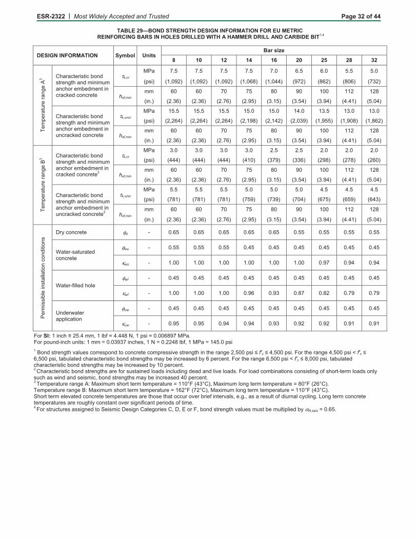
ESR-2322 | &����'���� ��������������������� Page 32 of 44 �
TABLE 29—BOND STRENGTH DESIGN INFORMATION FOR EU METRIC REINFORCING BARS IN HOLES DRILLED WITH A HAMMER DRILL AND CARBIDE BIT��<
DESIGN INFORMATION Symbol Units Bar size
8 10 12 14 16 20 25 28 32
!"+
�"��
���"
����
"�(
� � ������"��)����4����)��"�������+���+�+�������"+4"�+"����������-"�������"�"�
τ7����
23�� 01&� 01&� 01&� 01&� 01�� �1&� �1�� &1&� &1��
��)��� ����� �� ����� �� ����� �� �����/�� ����<<�� ��0 �� �/� �� �/���� �0� ��
�� �1���
++� ��� ��� 0�� 0&� /�� ��� ���� �� � � /�
���1�� � 1���� � 1���� � 10��� � 1�&�� ��1�&�� ��1&<�� ��1�<�� �<1<��� �&1�<��
������"��)����4����)��"�������+���+�+�������"+4"�+"������������-"�������"�"�
τ7������
23�� �&1&� �&1&� �&1&� �&1�� �&1�� �<1�� ��1&� ��1�� ��1��
��)��� � � �<�� � � �<�� � � �<�� � ���/�� � ��< �� � ������ ����&&�� �����/�� ���/� ��
�� �1���++� ��� ��� 0�� 0&� /�� ��� ���� �� � � /�
���1�� � 1���� � 1���� � 10��� � 1�&�� ��1�&�� ��1&<�� ��1�<�� �<1<��� �&1�<��
!"+
�"��
���"
����
"��
� � ������"��)����4����)��"�������+���+�+�������"+4"�+"����������-"�������"�" �
τ7����
23�� �1�� �1�� �1�� �1�� 1&� 1&� 1�� 1�� 1��
��)��� �<<<�� �<<<�� �<<<�� �<���� ��0��� ������ � �/�� � 0/�� � ����
�� �1���++� ��� ��� 0�� 0&� /�� ��� ���� �� � � /�
���1�� � 1���� � 1���� � 10��� � 1�&�� ��1�&�� ��1&<�� ��1�<�� �<1<��� �&1�<��
������"��)����4����)��"�������+���+�+�������"+4"�+"������������-"�������"�" �
τ7������
23�� &1&� &1&� &1&� &1�� &1�� &1�� <1&� <1&� <1&�
��)��� �0/��� �0/��� �0/��� �0&��� �0���� �0�<�� ��0&�� ��&��� ��<���
�� �1���++� ��� ��� 0�� 0&� /�� ��� ���� �� � � /�
���1�� � 1���� � 1���� � 10��� � 1�&�� ��1�&�� ��1&<�� ��1�<�� �<1<��� �&1�<��
3"�
+�)
)�4
"���
)��
����
����
�����
��)�
'��������"�"� φ�� $� �1�&� �1�&� �1�&� �1�&� �1�&� �1&&� �1&&� �1&&� �1&&�
G��"�$)������"�������"�"�
φ��� $� �1&&� �1&&� �1&&� �1<&� �1<&� �1<&� �1<&� �1<&� �1<&�
�� $� �1��� �1��� �1��� �1��� �1��� �1��� �1�0� �1�<� �1�<�
G��"�$.� "��� "�φ� � $� �1<&� �1<&� �1<&� �1<&� �1<&� �1<&� �1<&� �1<&� �1<&�
κ� � $� �1��� �1��� �1��� �1��� �1��� �1/0� �1/ � �10�� �10��
H��"�,��"����� ��������
φ��� $� �1<&� �1<&� �1<&� �1<&� �1<&� �1<&� �1<&� �1<&� �1<&�
�� $� �1�&� �1�&� �1�<� �1�<� �1��� �1� � �1� � �1��� �1���
;���SI:�������S� &1<�++���� 4.�E�<1<</�9�����)��E��1���/�0�23�1�;��������$��������)5���++�E��1����0����")����9�E��1 </� 4.����23��E��<&1���)���������)��"���*� �")�����")�������������"�"���+��"))�*"�)��"�������"����"� �&����)��C� G��C�<�&����)�1�;����"����"�<�&����)��T� G��C���&����)�����4� ��"��������"��)����4����)��"��)�+���4"�����"�)"��4�����"��"��1�;����"����"���&����)��T� G��C�/������)�����4� ��"��������"��)����4����)��"��)�+���4"�����"�)"��4������"��"��1� �������"��)����4����)��"��)���"�.���)�)����"�� ���)���� ������"������� �*"� ���)1�;��� ������+4�������)����)�)�����.�)���$�"�+� ���)��� ��)����)�,��������)"�)+����4����)��"��)�+���4"�����"�)"��<���"��"��1���!"+�"�����"����"�(5�2�6�+�+�)�����"�+��"+�"�����"�E����U;��<�U����2�6�+�+� ����"�+��"+�"�����"�E�/�U;�� �U��1�!"+�"�����"����"��5�2�6�+�+�)�����"�+��"+�"�����"�E��� U;��0 U����2�6�+�+� ����"�+��"+�"�����"�E����U;��<�U��1�������"�+�" "*��"�������"�"��"+�"�����")���"���)"������������*"��4��".����"�*� )��"11���)����")� ���.������� ���� ��1�I����"�+������"�"��"+�"�����")���"���� �����)������*"��)���.�������"����)��.���+"1�
<�;���)�������")��))��"������"�)+���'")������"���")����'��%����;��4����)��"���*� �")�+�)��4"�+� ��� �"��4��α(������E��1�&1�
�
� �

ESR-2322 | &����'���� ��������������������� Page 33 of 44 �
TABLE 30—BOND STRENGTH DESIGN INFORMATION FOR EU METRIC REINFORCING BARS IN HOLES DRILLED WITH A CORE DRILL��<
DESIGN INFORMATION Symbol Units Bar size
8 10 12 14 16 20 25 28 32
!"+
�"��
���"
���
�"�
(� � ������"��)����4����
)��"�������+���+�+�������"+4"�+"������������-"�������"�"�
τ7������
23�� � 1�� � 1�� � 1�� ��1&� ��1&� �1&� �1�� /1&� /1��
��)��� ���0<��� ���0<��� ���0<��� �����0�� ���&&��� ���<���� ��� ���� ��� �&�� ��������
�� �1���++� ��� ��� 0�� 0&� /�� ��� ���� ���� ����
���1�� 1��� � 1���� � 10��� � 1�&�� ��1�&�� ��1&<�� ��1�<�� �<1<��� �&1�<��
!"+
�"��
���"
���
�"�
�� � ������"��)����4����
)��"�������+���+�+�������"+4"�+"������������-"�������"�" �
τ7������
23�� <1�� <1�� <1�� <1�� �1&� �1&� �1�� �1�� �1��
��)��� ������ ������ ������ �&�&�� �&���� �<//�� �<<��� �< ��� �<�<��
�� �1���++� ��� ��� 0�� 0&� /�� ��� ���� �� � � /�
���1�� 1��� � 1���� � 10��� � 1�&�� ��1�&�� ��1&<�� ��1�<�� �<1<��� �&1�<��
3"�
+�)
)�4
"���
)��
����
����
�����
��) �
'��������"�"� φ�� $� �1�&� �1�&� �1�&� �1&&� �1&&� �1&&� �1<&� �1<&� �1<&�
G��"�$)������"�������"�"�
φ��� $� �1&&� �1&&� �1&&� �1<&� �1<&� �1<&� �1<&� �1<&� �1<&�
�� $� �1�� �1�� �1�� �1�� �1�� �1�� �1� � �1//� �1//�
;���SI:�������S� &1<�++���� 4.�E�<1<</�9�����)��E��1���/�0�23�1�;��������$��������)5���++�E��1����0����")����9�E��1 </� 4.����23��E��<&1���)���������)��"���*� �")�����")�������������"�"���+��"))�*"�)��"�������"����"� �&����)��C� G��C�<�&����)�1�;����"����"�<�&����)��T� G��C���&����)�����4� ��"��������"��)����4����)��"��)�+���4"�����"�)"��4�����"��"��1�;����"����"���&����)��T� G��C�/������)�����4� ��"��������"��)����4����)��"��)�+���4"�����"�)"��4������"��"��1� �������"��)����4����)��"��)���"�.���)�)����"�� ���)���� ������"������� �*"� ���)1�;��� ������+4�������)����)�)�����.�)���$�"�+� ���)��� ��)����)�,��������)"�)+����4����)��"��)�+���4"�����"�)"��<���"��"��1���!"+�"�����"����"�(5�2�6�+�+�)�����"�+��"+�"�����"�E����U;��<�U����2�6�+�+� ����"�+��"+�"�����"�E�/�U;�� �U��1�!"+�"�����"����"��5�2�6�+�+�)�����"�+��"+�"�����"�E��� U;��0 U����2�6�+�+� ����"�+��"+�"�����"�E����U;��<�U��1�������"�+�" "*��"�������"�"��"+�"�����")���"���)"������������*"��4��".����"�*� )��"11���)����")� ���.������� ���� ��1�I����"�+������"�"��"+�"�����")���"���� �����)������*"��)���.�������"����)��.���+"1�
<������)��"���*� �")���� ���4 "�����"�)+���'")������"���")�(��������� �1�
�� �

ESR-2322 | &����'���� ��������������������� Page 34 of 44 �
TABLE 31—STEEL DESIGN INFORMATION FOR CANADIAN METRIC REINFORCING BARS�
DESIGN INFORMATION Symbol Units Bar size
10 M 15 M 20 M 25 M 30 M
9�+��� �4������+"�"�� ��++� ��1�� ��1�� ��1&� &1 � �1��
���1�� ��1<<&�� ��1����� ��10�/�� ��1�� �� ��1�00��
����".."���*"����))$)"������ ���"�� ����
++ � ���1�� ��1�� �/1�� <�/1/� 0� 1 �
���1 �� ��1�&&�� ��1�� �� ��1<���� ��100��� ��1�//��
��
(�N
���
9�+��� �)��"����)��*"��"��4��)�"" �)��"���
(���-9� &<1�� ��/1&� ���1&� 0�1�� �/�1��
� 4�� �� ��0&�� � <�<�/�� ���� &&�� ����&</�� �/&� ����
)����-9� � 1&� �&1�� �01�� ���1&� 01&�
� 4�� �0���&�� ��<��<&�� � ��0&��� ����� ��� �&���<<��
�"��������.���)"�)+���)"��� α)������ $� �10��
���"����"��������.������φ�.����"�)��� � φ� $� �1�&�
���"����"��������.������φ�.���)"�� � φ� $� �1���
;���SI:�������S� &1<�++���� 4.�E�<1<</�9�����)��E��1���/�0�23�1�;��������$��������)5���++�E��1����0����")����9�E��1 </� 4.����23��E��<&1���)����A� �")����*��"��.�����++�������+��"��� ����")�4�)"�����)�"��.�"��)��"��)������� �� ��"��������������"�,���(�����/�%71��'$�������%71��'$ ��1�O�"��+��"��� �)�"��.�������)���"���+�))�4 "1�H)"����)�����,�)"�)�����������"�.����"�����)��"��1� �;����)"�,����"� ������+4�������)��.�(�����/��"�������1 ���)�)"��.�������(�����/��"������'1<1<1�
�TABLE 32—CONCRETE BREAKOUT DESIGN INFORMATION FOR CANADIAN
METRIC REINFORCING BARS IN HOLES DRILLED WITH A HAMMER DRILL AND CARBIDE BIT�
DESIGN INFORMATION Symbol Units Bar size
10 M 15 M 20 M 25 M 30 M
%.."���*"�"))�.������.�������-"�������"�"� 7�����
��� 01��
���$ 4�� ��0��
%.."���*"�"))�.������.���������-"�������"�"� 7�������
��� ���
���$ 4�� � <��
2��1�4���)������� �1���++� &0� /�� �/� � �� �&��
���1�� � 1 �� ��1��� ��1/�� �&1��� �&1���
2��1�"�"���)����"�� �1���++� &0� /�� �/� � �� �&��
���1�� � 1 �� ��1��� ��1/�� �&1��� �&1���
2���+�+�+"+4"�����-�"))� �1���++� �� �Q����
�� �Q� ������1�� ��� �Q���L<��
������� �"�"���)����"�M�)� ��������.���������-"�������"�"��
���� $� �""��"������<1�1����.���)��"����1�
���"����"��������.������.����"�)����������"�"�.�� ��"�+��")������������� �
φ� $� �1�&�
���"����"��������.������.���)"���������"�"�.�� ��"�+��")������������� �
φ� $� �10��
;���SI:�������S� &1<�++���� 4.�E�<1<</�9�����)��E��1���/�0�23�1�;��������$��������)5���++�E��1����0����")����9�E��1 </� 4.����23��E��<&1���)���(�������� �)"�������.��+�������)��")���4"�����;���"�&����)�� ��������)��������)1� �A� �")����*��"��.�����)�$��)�� "�������)���)�� "�����"��������������,������)��� "+"�������"��.���"+"��1���;�����)�� �����)�,�����L<�����"�"���)����"��"."������"������<1�1���.���)����������+�6�+�+����7�"��"7���"+"��)1�
�� �

ESR-2322 | &����'���� ��������������������� Page 35 of 44 �
TABLE 33—BOND STRENGTH DESIGN INFORMATION FOR CANADIAN METRIC REINFORCING BARS IN HOLES DRILLED WITH A HAMMER DRILL AND CARBIDE BIT��<
DESIGN INFORMATION Symbol Units Bar size
10 M 15 M 20 M 25 M 30 M
!"+
�"��
���"
����
"�(
� � ������"��)����4����)��"�������+���+�+�������"+4"�+"����������-"�������"�"�
τ7����
23�� 01&� 01�� 01�� �1�� &1&�
��)��� ����� �� ����<<�� ������ �/& �� �000��
�� �1���
++� �0� /�� ��� ���� � ��
���1�� � 1�&�� ��1�&�� ��1&<�� ��1�0�� �<10���
������"��)����4����)��"�������+���+�+�������"+4"�+"������������-"�������"�"�
τ7������
23�� �&1&� �&1�� �<1�� ��1&� ��1��
��)��� � � �<�� � ��< �� � ��&/�� ����&&�� ���//���
�� �1���++� �0� /�� ��� ���� � ��
���1�� � 1�&�� ��1�&�� ��1&<�� ��1�0�� �<10���
!"+
�"��
���"
����
"��
� � ������"��)����4����)��"�������+���+�+�������"+4"�+"����������-"�������"�" �
τ7����
23�� �1�� 1&� 1&� 1�� 1��
��)��� �<<<�� ��0��� ��< �� � �<�� � 0���
�� �1���++� �0� /�� ��� ���� � ��
���1�� � 1�&�� ��1�&�� ��1&<�� ��1�0�� �<10���
������"��)����4����)��"�������+���+�+�������"+4"�+"������������-"�������"�" �
τ7������
23�� &1&� &1�� &1�� <1&� <1&�
��)��� �0/��� �0���� �0���� ��0&�� ��<���
�� �1���++� �0� /�� ��� ���� � ��
���1�� � 1�&�� ��1�&�� ��1&<�� ��1�0�� �<10���
3"�
+�)
)�4
"���
)��
����
����
�����
��)�
'��������"�"� φ�� $� �1�&� �1�&� �1�&� �1&&� �1&&�
G��"�$)������"�������"�"�
φ��� $� �1&&� �1<&� �1<&� �1<&� �1<&�
�� $� �1�� �1�� �1�� �1�� �1���
G��"�$.� "��� "�φ� � $� �1<&� �1<&� �1<&� �1<&� �1<&�
κ� � $� �1��� �1��� �1��� �1/&� �1/��
H��"�,��"����� ��������
φ��� $� �1<&� �1<&� �1<&� �1<&� �1<&�
�� $� �1�&� �1�<� �1��� �1� � �1� �
;���SI:�������S� &1<�++���� 4.�E�<1<</�9�����)��E��1���/�0�23�1�;��������$��������)5���++�E��1����0����")����9�E��1 </� 4.����23��E��<&1���)���������)��"���*� �")�����")�������������"�"���+��"))�*"�)��"�������"����"� �&����)��C� G��C�<�&����)�1�;����"����"�<�&����)��T� G��C���&����)�����4� ��"��������"��)����4����)��"��)�+���4"�����"�)"��4�����"��"��1�;����"����"���&����)��T� G��C�/������)�����4� ��"��������"��)����4����)��"��)�+���4"�����"�)"��4������"��"��1� �������"��)����4����)��"��)���"�.���)�)����"�� ���)���� ������"������� �*"� ���)1�;��� ������+4�������)����)�)�����.�)���$�"�+� ���)��� ��)����)�,��������)"�)+����4����)��"��)�+���4"�����"�)"��<���"��"��1���!"+�"�����"����"�(5�2�6�+�+�)�����"�+��"+�"�����"�E����U;��<�U����2�6�+�+� ����"�+��"+�"�����"�E�/�U;�� �U��1�!"+�"�����"����"��5�2�6�+�+�)�����"�+��"+�"�����"�E��� U;��0 U����2�6�+�+� ����"�+��"+�"�����"�E����U;��<�U��1�������"�+�" "*��"�������"�"��"+�"�����")���"���)"������������*"��4��".����"�*� )��"11���)����")� ���.������� ���� ��1�I����"�+������"�"��"+�"�����")���"���� �����)������*"��)���.�������"����)��.���+"1�
<�;���)�������")��))��"������"�)+���'")������"���")����'��%����;��4����)��"���*� �")�+�)��4"�+� ��� �"��4��α(������E��1�&1�
� �


ESR-2322 | &����'���� ��������������������� Page 37 of 44 �
TABLE 35VALLOWABLE STRESS DESIGN EXAMPLE
Nominal anchor
diameter
Effective embedment
depth f’c k � � Nn
Allowable tension load
φNn/�
��� �� ����1�� ���1�� ��)��� �$�� �$�� �$�� � 4�� � 4��
�L/� �L/� �&��� <� �1</� �1�&� <��� � ��� /��L � �L<� �&��� <� �1</� �1�&� &�<0 � �<���&L/� ��L/� �&��� <� �1</� �1�&� ��� �� ������L<� ��L � �&��� <� �1</� �1�&� 0�/&0� ��<&�W�0L/� ��L �� �&��� 0� �1</� �1�&� /�/<�� ��// ��� <� �&��� 0� �1</� �1�&� ���/��� <�0<��
��L<� &� �&��� ��� �1</� �1�&� ���00�� 0���&�;���SI:��� 4�E�<1<&�-9�����)��E��1���/��23�������1�E� &1<�++�
�'")���())�+�����)5��1� ��� "�������,���)�������"�)���� ������ �F�(�!2�(�����N���"��0���"��"������ 1� A"����� ���,�,������)�� ���������"�������1� ��)�"�������"�+"��E�3"�������<1� ��)�� �������"+�"�����"�E�<��M���<U;�&1� I����"�+��"+�"�����"�E�/�U;��1� ������"�+��"+�"�����"�E����U;�01� '���� "�����������M����4��"���� "��� "�/1� %+4"�+"����"���E�".�+����1� �����"�"��"�"�+��"������"+����������-"��.����"� �."��.��"�������"���1� I������+4��������.��+�(�����/��"�������1 �����)"�)+��� ���������1� ��X�'"���I�����'������0�X�I�*"�I�����I�F������� ��� ������+4���������1 �'�Q��1��I�� 1� �� �� �������.�J�4�)"�����,"��"���*"��"5�J�E��1 �'�Q��1��I�E��1 ���1����Q��1����10���E��1</���1� 9��+� �,"��������"�"5� ���E� �&����)���<1� %�"���)����"�����4�����R������&1� 2"+4"�����-�"))���B��1����
* Verify capacity
Capacity ACI 318 Section Formula Calculation φ φNn
��"" � '1&1�� (���4�������(� ���� 9)��E��1��<&�B�� &����� �10&� ������� 4������"�"� '1&1 � (��4�7�. D�0���6��� �
���6� 9�4�E� <�B�� �&����1�&�B��1&�1�&� �1�&� &���0� 4������ '1&1��� (��4@����� � uncr,kτ � 9��E�π�B��L<�B��1&�B� ���&� �1�&� ������� 4�
Y(��E�&���0� 4�������"�"���)��"��)�*"�"��"��"�(�'�*� �"�,� �4"��� �� ��"���)�&���0� 4
�1</��E���<&�� 4�
�'")���"7����������*��"������"������<1�1<�%71��'$��.���� �

ESR-2322 | &����'���� ��������������������� Page 38 of 44 �
�
�
Dimensional parameters:
�� � � 4�;��������� � 4������������1��� � 4���6������� � 4������������ � 4��S������
Specifications/assumptions:
���&���;8�T�����$5����/�������������U("�����������6<8�T�����V*���>�������(��1������%������������� ���4����������������1���*���%��"���%�� �.�*"0�$�(��������1����� ����� �����%���������������������"!�8�:/�6�*�������������2����������1��1�>�1�1����������1�.�������0�����1����������1���������F����W�������1��1�>�1�1����%����1�����1����������1���������F�:��W�������1�������������������� ����������������11��/�������������������1������������������1����������7��� ������2������ ��� ��������%���
�
Calculation in accordance with ACI 318-05 Appendix D and this report ACI 318 Code Ref. Report Ref.
Step 1��"���7�1���1�1���%�������������������������%�����1�1�������7����3� /� �
�� �1���I��� ������ �����7�� � ��������6�8�
�1���4���6�����F����1�������� �����7�� /� �����:�
�1���4���6�����F�������� �����7�� /� �����:�
�1���4��� �A����6�4�;�A����6�4�����6�����F�������� �����7�� /� �����:�
Step 2��"��������������������%��3� =�� �� ���( � � ⋅ ⋅ � *�6����� /�
���&����;8�T�����$5��������1�� ������������� �φ∴ E � 0& � *�������*�����0� /�
�� �� ���( � � � � �φ φ∴ = ⋅ ⋅ ⋅ = ⋅ ⋅ ⋅� 0& � �<�� � & ��� �4��<�<�<���4��<�<�7�
��������%������5��∴ X��( 4 � � 4 �φ∴ ⋅ ⋅� 0& �0 0�0 � � - �
*�6����� �����5�
Step 3��*����1����������������7���������%��3� (��(�(��(��(�
(��% (
��( ⋅⋅⋅⋅⋅= ����
�
ψψψψ � *�6���������,-��.*/60� /�
� �1&(� � � ��1��� . � � 0. � � 0= ⋅ + ⋅ + 4�.�5�A��0.�8�6�A���60�4��;<����� /� /�
(� � � � � �= ⋅ 4�5�;����� *�6���������,-��.*/<0� /�
FIGURE 4VDESIGN EXAMPLE �
� �
�
�L $�91�(�����0�(II$!#�%('
��
���1��
�1�>
�����
��
( (
�
��1��
��
����(�
���(�
���(�
�(�
�(�
($(
(
(
�S�
�S�
�
�L $�91�(�����0�(II$!#�%('
�
�
�
��1��
1�>
�����
��
� �
���1��
�
����(�
�����(�
�����(�
�(�
�(�
� $�
�
(
�S�
�S�

ESR-2322 | &����'���� ��������������������� Page 39 of 44 �
Calculation in accordance with ACI 318-05 Appendix D and this report ACI 318 Code Ref. Report Ref.
(���ψ 4������������������� �� �������������������������������������/��������������� *�6����� �
� 0 � �� &
��1���� �(
�
�� �
� �ψ = + ⋅ � ��� �1&��1�� � � �≤ � *�6���6�����
,-��.*/��0� /�
95.15.2c min,a ⋅<= � /� /�
"��9 1&�10 �1� �10�
�1& �ψ∴ = + ⋅ =
⋅� /� /�
(��ψ �4�����������7����������������1���.7�������4���0� *�6���<� �����:�
*����1�������3�
( ) ( ) �� � �1�� �� � � � � � � � �
�10& � 0&& � � & & �/ � ��1 � 1� ��1 1&+ = + = > ∴ = ⋅ �
( )��� 1& �1� ��1 1& ��1= = �
*�6���5� ������������8�
������1���I����� ��1�� � ���(
��
1�> � J � � 1�> � ��� �
� & & F� & �� �� &ψ
⋅ ⋅= = = � *�6���5������
,-��.*/�80� /�
( ) �� � ����� � � ( 7 C � � � �� &� & < < ��� � � <� �/� 4= ⋅ = ⋅ = � *�6���������,-��.*/50� /�
�%( <�� �1� �10� �1� �1�� <���/� � �0�& 40 �
= ⋅ ⋅ ⋅ ⋅ ⋅ = � /� /�
�%( � � �� �& � 0�& / �& 4 /1� -φ = ⋅ = = � *�����0� /�
Step 4��*����1�������������%��3� ��(���(����(�%�(����(��
(��% (
��
( ⋅⋅⋅⋅⋅= ψψψψ � /� ������������,-��.*/�<0�
����(��4�1��� 20 3⋅ ⋅�
���
�
��� = ⋅ ⋅ =� �7�����
�
τ��<&�
� �1& � �&��<&�
� 1<���1; �
�
� �� �(�8 � � 0 ��1 � 1< ��1 � 1< ��1⋅ = ≥ ∴ = �
/� �����������������;�
�� �(����(�
�� �1 ��1
= = � /� ������������,-��.*/�<�0�
( ) ( )(� �� �(� �� �(� � �1��� �� � � � �<�1� ��= + + = � /� ������������*�6�8�5�
( )�(�� �� �(�� � �&<1 ��= = � /� ������������
*�6�8�5�
��� ��1�� ���(�� �< 3� ��1��
���(�
��"��9� �10 �1�ψ
� �= + ⋅� �� �� �
� /� ������������
"��9� 1&�10 �1� �1/ �1
ψ � �= + ⋅ =� �� �
� /� ������������
������7�1�>����� � �
7� C
� < �1� <���� �/�� �)�
�1&τ
π π= ⋅ = ⋅ =
⋅ ⋅� /�
�����������������:�
H%�(���E� � � 7�����
7�1�>�����– – – ( – )� �
� �& �/��
�1���1& �1&
⋅�
��
�
��
��
�
�
= ⋅���
���
��
�
�
=τ
τ� /�
�����������������;�
��
FIGURE 4VDESIGN EXAMPLE (Continued) � �

ESR-2322 | &����'���� ��������������������� Page 40 of 44 �
Calculation in accordance with ACI 318-05 Appendix D and this report ACI 318 Code Ref. Report Ref.
( ) ( )%�(� %�(�� %�(�����(�
��
�1& �1&<1�� �1�� � �1�� �1��� 1<
ψ ψ ψ � �� � � �� = + ⋅ − = + ⋅ − =� � � � �� �� � �� � � � �
�
/� ������������
=(����ψ ������������������ �/�������%��������������� /� /�
��1�� ���(�
��
1�> � � 1�>���9�
F 1& F �1 �1 / 1&ψ = = = � /� /�
(���E� uncr,kτ �B�@�B���B��� �E� � �&�B�@�B��1&�B��1��E�������� 4� /� ������������,-��.*/�< 0�
��(���(����(�%�(����(��
(��% (
��
( ⋅⋅⋅⋅⋅= ψψψψ �
�%( �<�1� �1/ �1�� �1� �1 / ������ 0���< 4�&<1
= ⋅ ⋅ ⋅ ⋅ ⋅ = �
/� ������������,-��.*/�<�0�
�1�&φ = � /� �����;�
�%( �1�& 0���< <���0 4 <1� -φ∴ = ⋅ = = � � /�
Step 5��*����1��������������%������%��3� *������� /������������%��� φ(��� 4��<�<�7� � � �
"�����������7���������%��� φ(�%� 4�:�8�7� � � �$���������%��� φ(�%�� 4���<�7� ��������� � �
�����<��"��2���������%��������*�����%� ���������2�������������������3� � �
� lb108,348.16.4NN
N ndag ====
αφ
α�
(���3����������>�1����8�Y������������5�Y���2�����������������������%��������1��������� ����*�A���<Z��������1��3�O�4���8[����A���5[��<�4����:��
� ������������
�
FIGURE 4VSAMPLE CALCULATION (Continued)�
�

ESR-2322 | &����'���� ��������������������� Page 41 of 44 �
FIGURE 5—INSTALLATION INSTRUCTIONS

ESR-2322 | &����'���� ��������������������� Page 42 of 44 �
FIGURE 5—INSTALLATION INSTRUCTIONS (Continued)

ESR-2322 | &����'���� ��������������������� Page 43 of 44 �
FIGURE 5—INSTALLATION INSTRUCTIONS (Continued)

ESR-2322 | &����'���� ��������������������� Page 44 of 44 ��
FIGURE 5—INSTALLATION INSTRUCTIONS (Continued)