cisco ucs configuration principles for shared storage · cisco ucs configuration principles for...
TRANSCRIPT
© 2014 Cisco and/or its affiliates. All rights reserved. This document is Cisco Public. Page 1 of 150
White Paper
SAP HANA Tailored Datacenter Integration Option
Cisco UCS Configuration Principles for Shared Storage
March 2014

© 2014 Cisco and/or its affiliates. All rights reserved. This document is Cisco Public. Page 2 of 150
Contents
Table of Figures ....................................................................................................................................................... 3
Introduction .............................................................................................................................................................. 8
Global Hardware Requirements for the SAP HANA Database ............................................................................. 8 CPU ...................................................................................................................................................................... 8 Memory ................................................................................................................................................................. 9 CPU and Memory Combinations ........................................................................................................................... 9 Network ............................................................................................................................................................... 10 Storage ............................................................................................................................................................... 12 File System Sizes ............................................................................................................................................... 13 Operating System ............................................................................................................................................... 14 Boot Options ....................................................................................................................................................... 14 High Availability ................................................................................................................................................... 14
Cisco Solution for SAP HANA Scale-Out Design ................................................................................................ 15 Cisco UCS Configuration .................................................................................................................................... 17 Server Pool Policy ............................................................................................................................................... 22 BIOS Policy ......................................................................................................................................................... 23 Serial over LAN Policy ........................................................................................................................................ 26 Maintenance Policies .......................................................................................................................................... 27 Intelligent Platform Management Interface Access Profile .................................................................................. 28 Service Profile Template Configuration ............................................................................................................... 36 Service Profile Deployment ................................................................................................................................. 42
Cisco Solution for SAP HANA Tailored Datacenter Integration ........................................................................ 45 PortChannel Connection ..................................................................................................................................... 46 Pinning Option with Eight Uplinks ....................................................................................................................... 49 Storage Connectivity Options .............................................................................................................................. 50
Boot Options .......................................................................................................................................................... 97 PXE Boot ............................................................................................................................................................ 98 SAN Boot ............................................................................................................................................................ 98 Local Disk Boot ................................................................................................................................................. 100
Operating System Installation ............................................................................................................................ 105 SUSE Linux Enterprise Server .......................................................................................................................... 105 Operating System Configuration ....................................................................................................................... 118 Linux Kernel Crash Dump ................................................................................................................................. 121
Storage Access for SAP HANA .......................................................................................................................... 132 Block Storage for SAP HANA Data and Log Files ............................................................................................ 132 File Storage for SAP HANA Data and Log Files ............................................................................................... 134 Block Storage for SAP HANA Shared File System ........................................................................................... 137 File Storage for /hana/shared ............................................................................................................................ 137
Cisco UCS Solution for SAP HANA TDI: Shared Network ................................................................................ 138 Multiple SAP HANA SIDs in One Appliance...................................................................................................... 139 SAP HANA and SAP Application Server in One Appliance .............................................................................. 140 SAP HANA in an Existing Cisco UCS Deployment ........................................................................................... 141
Conclusion ........................................................................................................................................................... 142
For More Information ........................................................................................................................................... 142
Appendix: Direct-Attached NFS Failure Scenarios ........................................................................................... 142 Network-Attached Storage and Cisco UCS Appliance Ports ............................................................................ 142 Summary of Failure Recovery Principles .......................................................................................................... 150
© 2014 Cisco and/or its affiliates. All rights reserved. This document is Cisco Public. Page 3 of 150
Table of Figures
Figure 1. High-Level SAP HANA Network Overview ..................................................................................... 11
Figure 2. File System Layout .......................................................................................................................... 13
Figure 3. Cisco Solution for SAP HANA Scale-Out Design .......................................................................... 16
Figure 4. Chassis Discovery Policy ................................................................................................................ 18
Figure 5. IOM Fabric Ports with Pinning Mode .............................................................................................. 18
Figure 6. IOM Fabric Ports with Port Channel Mode ..................................................................................... 18
Figure 7. Power Policy ..................................................................................................................................... 19
Figure 8. Power Control Policy for SAP HANA Nodes .................................................................................. 19
Figure 9. Server Pool Policy Qualification HANA-512GB-4870 .................................................................... 20
Figure 10. CPU Qualification Properties .......................................................................................................... 20
Figure 11. Memory Qualification Properties .................................................................................................... 21
Figure 12. Server Pool ....................................................................................................................................... 21
Figure 13. Server Pool Policy HANA-512GB-4870 ........................................................................................... 22
Figure 14. List of Servers in Server Pool HANA-512GB-4870 ........................................................................ 22
Figure 15. BIOS Policy Main Settings .............................................................................................................. 23
Figure 16. BIOS Policy: Advanced > Processor .............................................................................................. 23
Figure 17. BIOS Policy: Advanced > Intel Directed IO .................................................................................... 24
Figure 18. BIOS Policy: Advanced > RAS Memory ......................................................................................... 24
Figure 19. BIOS Policy: Advanced > Serial Port ............................................................................................. 24
Figure 20. BIOS Policy: Advanced > USB ........................................................................................................ 25
Figure 21. BIOS Policy: Advanced > PCI Configuration ................................................................................. 25
Figure 22. BIOS Policy: Boot Options .............................................................................................................. 25
Figure 23. BIOS Policy: Server Management .................................................................................................. 26
Figure 24. Serial over LAN Policy ..................................................................................................................... 26
Figure 25. Maintenance Policy .......................................................................................................................... 27
Figure 26. IPMI Access Profile .......................................................................................................................... 28
Figure 27. Adapter Policy Linux-B440 .............................................................................................................. 29
Figure 28. Network Paths with Cisco UCS ....................................................................................................... 30
Figure 29. VLAN Definition in Cisco UCS (Old) ............................................................................................... 31
Figure 30. VLAN Definition in Cisco UCS (New) .............................................................................................. 32
Figure 31. VLAN Groups in Cisco UCS ............................................................................................................ 33
Figure 32. VLAN Groups: Uplink PortChannels for VLAN Group Admin-Zone ............................................ 33
Figure 33. vNIC Templates (Old) ....................................................................................................................... 34
Figure 34. vNIC Templates (New) ..................................................................................................................... 34
Figure 35. vNIC Template Details ..................................................................................................................... 35
Figure 36. Create vHBA Template .................................................................................................................... 36
Figure 37. Service Profile Template: General Tab........................................................................................... 37
Figure 38. Service Profile Template: Storage Tab (New) ................................................................................ 38
© 2014 Cisco and/or its affiliates. All rights reserved. This document is Cisco Public. Page 4 of 150
Figure 39. Service Profile Template: Network Tab (Old) ................................................................................ 39
Figure 40. vNIC and vHBA Placement for Slots 1 and 3 (Old) ........................................................................ 39
Figure 41. vNIC and vHBA Placement for Slots 5 and 7 (Old) ........................................................................ 40
Figure 42. Service Profile Template: Boot Order Sample for PXE Boot ........................................................ 40
Figure 43. Service Profile Template: Policies Tab (Part 1) ............................................................................. 41
Figure 44. Service Profile Template: Policies Tab (Part 2) ............................................................................. 41
Figure 45. Service Profile Template: Before Service Profiles Are Created ................................................... 42
Figure 46. Create Service Profile From Template ........................................................................................... 42
Figure 47. Defined Service Profiles .................................................................................................................. 43
Figure 48. Service Profile Details for Service Profile Template ..................................................................... 43
Figure 49. Service Profile: Storage Tab ........................................................................................................... 44
Figure 50. Service Profile: Network Tab .......................................................................................................... 44
Figure 51. Service Profile: Policies Tab ........................................................................................................... 45
Figure 52. Chassis Discovery Policy ................................................................................................................ 46
Figure 53. Chassis Connectivity Policy ........................................................................................................... 46
Figure 54. LAN Connectivity Policy .................................................................................................................. 47
Figure 55. Create a vNIC for LAN Connectivity Policy .................................................................................... 48
Figure 56. Modify vNIC/vHBA Placement for PortChannel ............................................................................. 48
Figure 57. Service Profile Template: Network Tab .......................................................................................... 49
Figure 58. Fabric Interconnect: Configure Unified Ports ............................................................................... 50
Figure 59. Unified Ports: Configure Fixed Module Ports ................................................................................ 51
Figure 60. Unified Ports: Configure Expansion Module Ports ....................................................................... 52
Figure 61. VSAN Configuration......................................................................................................................... 52
Figure 62. Fibre Channel Port Details .............................................................................................................. 53
Figure 63. Fibre Channel PortChannel Details ................................................................................................ 53
Figure 64. SAN-Based Fibre Channel Storage ................................................................................................ 56
Figure 65. Fabric Interconnect Details ............................................................................................................. 57
Figure 66. Fibre Channel Port Details .............................................................................................................. 57
Figure 67. Create vHBA Template .................................................................................................................... 58
Figure 68. Create SAN Connectivity Policy ..................................................................................................... 58
Figure 69. Create vHBA ..................................................................................................................................... 59
Figure 70. Service Profile Template: Storage Tab (New) ................................................................................ 59
Figure 71. Direct Attached Fibre Channel Storage ......................................................................................... 60
Figure 72. Fabric Interconnect Details ............................................................................................................. 61
Figure 73. Configure Fibre Channel Storage Ports ......................................................................................... 62
Figure 74. Fibre Channel Storage Ports ........................................................................................................... 62
Figure 75. Storage Connection Policy: Start ................................................................................................... 63
Figure 76. Fabric A: Storage Controller 1 ........................................................................................................ 64
Figure 77. Fabric A: Storage Controller 2 ........................................................................................................ 64

© 2014 Cisco and/or its affiliates. All rights reserved. This document is Cisco Public. Page 5 of 150
Figure 78. Fabric B: Storage Controller 1 ........................................................................................................ 64
Figure 79. Fabric B: Storage Controller 2 ........................................................................................................ 65
Figure 80. Storage Connection Policy ............................................................................................................. 65
Figure 81. vHBA Initiator Groups List .............................................................................................................. 66
Figure 82. Create vHBA Initiator Group ........................................................................................................... 66
Figure 83. vHBA Initiator Group Configuration in Service Profile Template and Service Profiles ............. 67
Figure 84. LAN-Attached FCoE Storage .......................................................................................................... 68
Figure 85. VSAN Details: Verify the FCoE VLAN ID ........................................................................................ 69
Figure 86. LAN PortChannel ............................................................................................................................. 70
Figure 87. Create FCoE PortChannel: Part 1 ................................................................................................... 70
Figure 88. Create FCoE PortChannel: Part 2 ................................................................................................... 71
Figure 89. Create FCoE Port Channel: Finished ............................................................................................. 71
Figure 90. Ethernet Port: General Tab ............................................................................................................. 72
Figure 91. SAN Pin Group ................................................................................................................................. 72
Figure 92. vHBA Template Details: SAN Pin Group ........................................................................................ 73
Figure 93. Direct-Attached FCoE Storage ........................................................................................................ 74
Figure 94. Ethernet Port Details: Configure as FCoE Storage Port ............................................................... 75
Figure 95. Ethernet Port Details: FCoE Storage .............................................................................................. 75
Figure 96. vHBA Details .................................................................................................................................... 76
Figure 97. Direct-Attached NFS Storage .......................................................................................................... 77
Figure 98. Appliance Section on the LAN tab ................................................................................................. 77
Figure 99. Configure Port as Appliance Port ................................................................................................... 78
Figure 100. Appliance Port Configuration Details: No VLAN Configured .................................................. 79
Figure 101. Create VLAN for the Appliance Section ..................................................................................... 80
Figure 102. Appliance Port Configuration Details Including the NFS Storage VLAN ................................ 81
Figure 103. Port Details ................................................................................................................................... 82
Figure 104. Appliance Section After Ports Are Configured ......................................................................... 82
Figure 105. Create VLAN for PXE Boot and NFS Root in Appliances Section ........................................... 83
Figure 106. Add NFS-Boot VLAN to an Appliance Port ................................................................................ 84
Figure 107. Appliances Section After VLAN Configuration ......................................................................... 85
Figure 108. LAN-Attached NFS Storage ........................................................................................................ 85
Figure 109. Port and Port Channel Configuration ........................................................................................ 86
Figure 110. VLAN Groups ............................................................................................................................... 87
Figure 111. Create VLAN Group ..................................................................................................................... 88
Figure 112. Create VLAN Group: Port Selection ........................................................................................... 89
Figure 113. Create VLAN Group: PortChannel Selection ............................................................................. 90
Figure 114. VLAN Groups List Including the Storage Group....................................................................... 91
Figure 115. VLAN T01-Storage Details .......................................................................................................... 92
Figure 116. T01-Storage vNIC Template Details ........................................................................................... 92

© 2014 Cisco and/or its affiliates. All rights reserved. This document is Cisco Public. Page 6 of 150
Figure 117. NFS Storage Directly Attached to Solution Switches ............................................................... 93
Figure 118. Cisco Nexus Port Diagram .......................................................................................................... 94
Figure 119. NFS Storage Indirectly Attached to Solution Switches ............................................................ 97
Figure 120. Boot Policy Example for PXE Boot ............................................................................................ 98
Figure 121. Boot Policy Example for SAN Boot: NetApp FAS ..................................................................... 99
Figure 122. Boot Policy Example for SAN Boot: EMC VNX ......................................................................... 99
Figure 123. KVM Console: VIC Boot Driver Detects SAN LUN .................................................................. 100
Figure 124. Local Disk Configuration Policy ............................................................................................... 101
Figure 125. Service Profile Template: Storage Tab .................................................................................... 101
Figure 126. Service Profile Template: Change Local Disk Configuration Policy ..................................... 102
Figure 127. Service Profile Template with Local Disk Policy .................................................................... 102
Figure 128. Service Profile Template: Boot Order ...................................................................................... 103
Figure 129. Service Profile Template: Modify Boot Policy ......................................................................... 104
Figure 130. KVM Screen: LSI RAID Configuration Summary .................................................................... 105
Figure 131. Virtual Media: Add Image .......................................................................................................... 106
Figure 132. Virtual Media: Mapped SLES ISO ............................................................................................. 107
Figure 133. Boot Selection Screen ............................................................................................................... 108
Figure 134. Error: No Hard Disk Found ....................................................................................................... 109
Figure 135. Clock and Time Zone ................................................................................................................. 110
Figure 136. Set Default Run Level ................................................................................................................ 111
Figure 137. Software Selection..................................................................................................................... 112
Figure 138. Installation Settings Summary: Software Packages............................................................... 113
Figure 139. Installation Settings Summary: Partitioning for Local Disk Boot.......................................... 114
Figure 140. NFS Root File System ............................................................................................................... 115
Figure 141. Network Configuration .............................................................................................................. 116
Figure 142. User Authentication Method ..................................................................................................... 117
Figure 143. Linux Login Screen ................................................................................................................... 118
Figure 144. Log Into Serial Console ............................................................................................................. 119
Figure 145. Serial Console POST Screen .................................................................................................... 120
Figure 146. Serial Console Boot Menu ........................................................................................................ 120
Figure 147. Serial Console OS Booted ........................................................................................................ 121
Figure 148. Configure User Defined Macros ............................................................................................... 123
Figure 149. SysRq Emergency Sync Console Message ............................................................................ 123
Figure 150. Equipment > Servers with General Tab and Adapter Folder Open ....................................... 124
Figure 151. Servers > Service Profile XYZ with Network Tab Open .......................................................... 125
Figure 152. Linux: ifconfig –a |grep HWaddr............................................................................................... 125
Figure 153. Equipment > Servers with General Tab Open ......................................................................... 126
Figure 154. Servers > Service Profile XYZ with Network Tab Open .......................................................... 127
Figure 155. Linux: ifconfig –a |grep HWaddr............................................................................................... 128

© 2014 Cisco and/or its affiliates. All rights reserved. This document is Cisco Public. Page 7 of 150
Figure 156. DM-MPIO with Persistent Group Reservation (PGR) on EMC VNX5300 ............................... 132
Figure 157. SAP HANA TDI: Two SAP HANA SIDs in One Appliance ....................................................... 139
Figure 158. SAP HANA TDI: Database and Application in One Appliance ............................................... 140
Figure 159. SAP HANA TDI: SAP HANA in a FlexPod Solution ................................................................. 141
Figure 160. Steady-State Direct-Connect Appliance Ports with NFS ........................................................ 143
Figure 161. Failure Scenario 1: Fabric Interconnect Is Lost ...................................................................... 144
Figure 162. Data Path Upon Recovery of Fabric Interconnect .................................................................. 145
Figure 163. Failure Scenario 2: Loss of IOM ............................................................................................... 146
Figure 164. Failure Scenario 3: Loss of Appliance Port Links .................................................................. 147
Figure 165. Failure Scenario 4: Loss of Last Uplink Port on Fabric Interconnect ................................... 148
Figure 166. Failure Scenario 5: Loss of NetApp Controller ....................................................................... 149
Modification History
Revision Date Originator
1.0 Mar 2014 Ulrich Kleidon
© 2014 Cisco and/or its affiliates. All rights reserved. This document is Cisco Public. Page 8 of 150
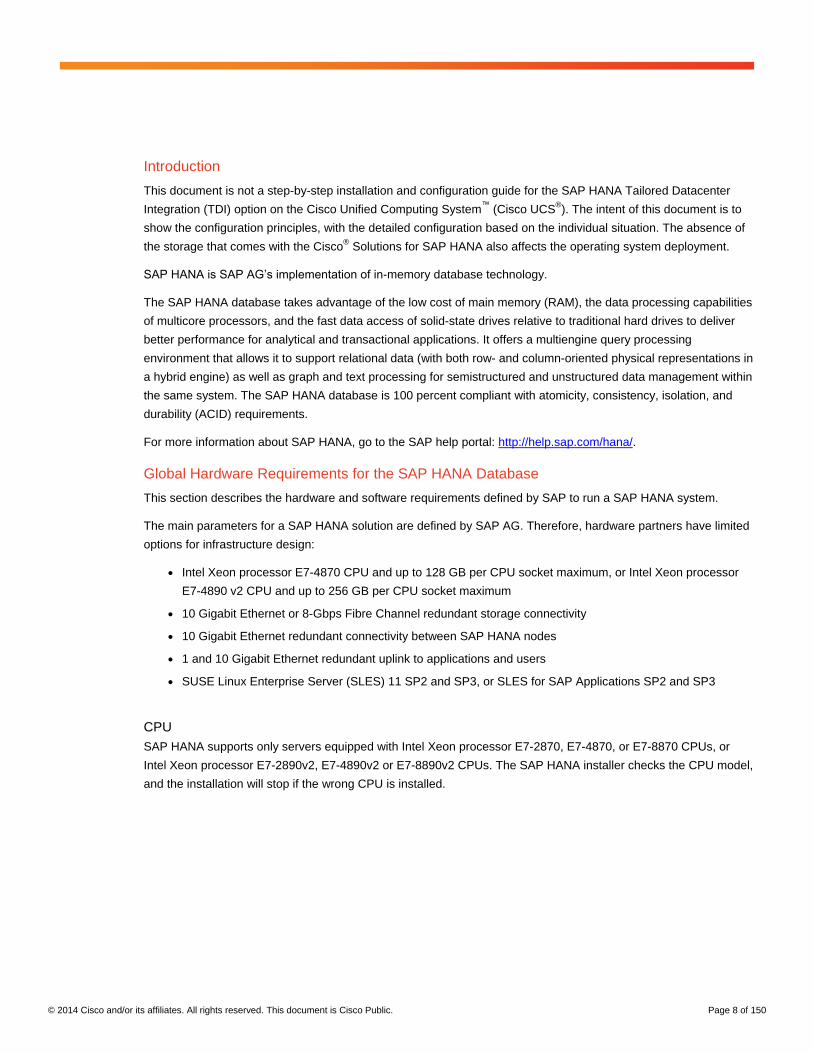
Introduction
This document is not a step-by-step installation and configuration guide for the SAP HANA Tailored Datacenter
Integration (TDI) option on the Cisco Unified Computing System™
(Cisco UCS®). The intent of this document is to
show the configuration principles, with the detailed configuration based on the individual situation. The absence of
the storage that comes with the Cisco® Solutions for SAP HANA also affects the operating system deployment.
SAP HANA is SAP AG’s implementation of in-memory database technology.
The SAP HANA database takes advantage of the low cost of main memory (RAM), the data processing capabilities
of multicore processors, and the fast data access of solid-state drives relative to traditional hard drives to deliver
better performance for analytical and transactional applications. It offers a multiengine query processing
environment that allows it to support relational data (with both row- and column-oriented physical representations in
a hybrid engine) as well as graph and text processing for semistructured and unstructured data management within
the same system. The SAP HANA database is 100 percent compliant with atomicity, consistency, isolation, and
durability (ACID) requirements.
For more information about SAP HANA, go to the SAP help portal: http://help.sap.com/hana/.
Global Hardware Requirements for the SAP HANA Database
This section describes the hardware and software requirements defined by SAP to run a SAP HANA system.
The main parameters for a SAP HANA solution are defined by SAP AG. Therefore, hardware partners have limited
options for infrastructure design:
● Intel Xeon processor E7-4870 CPU and up to 128 GB per CPU socket maximum, or Intel Xeon processor
E7-4890 v2 CPU and up to 256 GB per CPU socket maximum
● 10 Gigabit Ethernet or 8-Gbps Fibre Channel redundant storage connectivity
● 10 Gigabit Ethernet redundant connectivity between SAP HANA nodes
● 1 and 10 Gigabit Ethernet redundant uplink to applications and users
● SUSE Linux Enterprise Server (SLES) 11 SP2 and SP3, or SLES for SAP Applications SP2 and SP3
CPU
SAP HANA supports only servers equipped with Intel Xeon processor E7-2870, E7-4870, or E7-8870 CPUs, or
Intel Xeon processor E7-2890v2, E7-4890v2 or E7-8890v2 CPUs. The SAP HANA installer checks the CPU model,
and the installation will stop if the wrong CPU is installed.

© 2014 Cisco and/or its affiliates. All rights reserved. This document is Cisco Public. Page 9 of 150
Memory
The variety of main memory configurations is limited. SAP HANA is supported only if the memory configuration
follows these rules:
● Homogenous symmetric assembly of DIMMs (no mixture of DIMM size or speed)
● Maximum utilization of all available memory channels
● 64, 128, or 256 GB of memory per socket for SAP NetWeaver Business Warehouse (BW) and datamart
● 64, 126, 256, or 512 GB of memory per socket for SAP Business Suite on SAP HANA (SoH) on 2-socket or
4-socket server
● Maximum supported memory per socket for SoH on 8-socket server
CPU and Memory Combinations
On the basis of the requirements listed in this document, servers for SAP HANA must be configured as shown
in Table 1.
Table 1. CPU and Memory Configurations for SAP HANA
Intel Xeon (Westmere Generation) Processors: E7-2870, E7-4870, and E7-8870
Scale Up Scale Out
128 GB RAM 2x Intel Xeon processor E7-x870 CPU on 2- or 4-socket server system
256 GB 2x Intel Xeon processor E7-x870 CPU on 2- or 4-socket server system
256 GB RAM 2x Intel Xeon processor E7-x870 CPU on 2- or 4-socket server system
512 GB 4x Intel Xeon processor E7-x870 CPU on 4- or 8-socket server system
512 GB RAM 2x Intel Xeon processor E7-x870 CPU on 2- or 4-socket server system (SoH only)
1.0 TB RAM 8x Intel Xeon processor E7-x870 CPU on 8-socket server system
512 GB RAM 4x Intel Xeon processor E7-x870 CPU on 4- or 8-socket server system
2.0 TB RAM 8x Intel Xeon processor E7-x870 CPU on 8-socket server system (SoH only)
1.0 TB RAM 4x Intel Xeon processor E7-x870 CPU on 4-socket server system (SoH only)
1.0 TB RAM 8x Intel Xeon processor E7-x870 CPU on 8-socket server system
2.0 TB RAM 8x Intel Xeon processor E7-x870 CPU on 8-socket server system
Intel Xeon (Ivy Bridge Generation) Processors: E7-2890 v2, E7-4890 v2, and E7-8890 v2
Scale-Up Scale Out
128 GB RAM 2x Intel Xeon processor E7-x890v2 CPU on 2- or 4-socket server system
512 GB RAM 2x Intel Xeon processor E7-x890v2 CPU on 2-socket server system
256 GB RAM 2x Intel Xeon processor E7-x890v2 CPU on 2- or 4-socket server system
512 GB RAM 4x Intel Xeon processor E7-x890v2 CPU on 4- or 8-socket server system
512 GB RAM 2x Intel Xeon processor E7-x890v2 CPU on 2- or 4-socket server system
1.0 TB RAM 4x Intel Xeon processor E7-x890v2 CPU on 4- or 8-socket server system
1.0 TB RAM 4x Intel Xeon processor E7-x890v2 CPU on 4- or 8-socket server system
2.0 TB RAM 8x Intel Xeon processor E7-x890v2 CPU on 8-socket server system
2.0 TB RAM 4x Intel Xeon processor E7-x890v2 CPU on 4-socket server system (SoH only)
4.0 TB RAM 8x Intel Xeon processor E7-x890v2 CPU on 8-socket server system (SoH only)
2.0 TB RAM 8x Intel Xeon processor E7-x890v2 CPU on 8-socket server system
6.0 TB RAM 8x Intel Xeon processor E7-x890v2 CPU on 8-socket server system (SoH only)
4.0 TB RAM 8x Intel Xeon processor E7-x890v2 CPU on 8-socket server system (SoH only)
6.0 TB RAM 8x Intel Xeon processor E7-x890v2 CPU on 8-socket server system (SoH only)
© 2014 Cisco and/or its affiliates. All rights reserved. This document is Cisco Public. Page 10 of 150
Network
A SAP HANA data center deployment can range from a database running on a single host to a complex distributed
system with multiple hosts located at a primary site and one or more secondary sites and supporting a distributed
multiterabyte database with full fault and disaster recovery.
SAP HANA has different types of network communication channels to support the different SAP HANA scenarios
and setups:
● Client zone: Channels used for external access to SAP HANA functions by end-user clients, administration
clients, and application servers, and for data provisioning through SQL or HTTP
● Internal zone: Channels used for SAP HANA internal communication within the database or, in a distributed
scenario, for communication between hosts
● Storage zone: Channels used for storage access (data persistence) and for backup and restore procedures
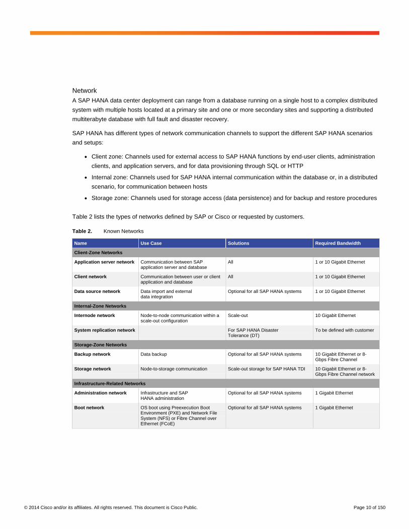
Table 2 lists the types of networks defined by SAP or Cisco or requested by customers.
Table 2. Known Networks
Name Use Case Solutions Required Bandwidth
Client-Zone Networks
Application server network Communication between SAP application server and database
All 1 or 10 Gigabit Ethernet
Client network Communication between user or client application and database
All 1 or 10 Gigabit Ethernet
Data source network Data import and external data integration
Optional for all SAP HANA systems 1 or 10 Gigabit Ethernet
Internal-Zone Networks
Internode network Node-to-node communication within a scale-out configuration
Scale-out 10 Gigabit Ethernet
System replication network For SAP HANA Disaster Tolerance (DT)
To be defined with customer
Storage-Zone Networks
Backup network Data backup Optional for all SAP HANA systems 10 Gigabit Ethernet or 8-Gbps Fibre Channel
Storage network Node-to-storage communication Scale-out storage for SAP HANA TDI 10 Gigabit Ethernet or 8-Gbps Fibre Channel network
Infrastructure-Related Networks
Administration network Infrastructure and SAP HANA administration
Optional for all SAP HANA systems 1 Gigabit Ethernet
Boot network OS boot using Preexecution Boot Environment (PXE) and Network File System (NFS) or Fibre Channel over Ethernet (FCoE)
Optional for all SAP HANA systems 1 Gigabit Ethernet
© 2014 Cisco and/or its affiliates. All rights reserved. This document is Cisco Public. Page 11 of 150
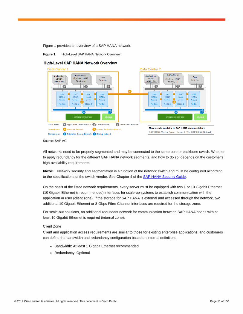
Figure 1 provides an overview of a SAP HANA network.
Figure 1. High-Level SAP HANA Network Overview
Source: SAP AG
All networks need to be properly segmented and may be connected to the same core or backbone switch. Whether
to apply redundancy for the different SAP HANA network segments, and how to do so, depends on the customer’s
high-availability requirements.
Note: Network security and segmentation is a function of the network switch and must be configured according
to the specifications of the switch vendor. See Chapter 4 of the SAP HANA Security Guide.
On the basis of the listed network requirements, every server must be equipped with two 1 or 10 Gigabit Ethernet
(10 Gigabit Ethernet is recommended) interfaces for scale-up systems to establish communication with the
application or user (client zone). If the storage for SAP HANA is external and accessed through the network, two
additional 10 Gigabit Ethernet or 8-Gbps Fibre Channel interfaces are required for the storage zone.
For scale-out solutions, an additional redundant network for communication between SAP HANA nodes with at
least 10 Gigabit Ethernet is required (internal zone).
Client Zone
Client and application access requirements are similar to those for existing enterprise applications, and customers
can define the bandwidth and redundancy configuration based on internal definitions.
● Bandwidth: At least 1 Gigabit Ethernet recommended
● Redundancy: Optional

© 2014 Cisco and/or its affiliates. All rights reserved. This document is Cisco Public. Page 12 of 150
Internal Zone
The internal zone is a critical part of the SAP HANA solution, and the bandwidth is measured in all SAP HANA TDI
implementations. The test tool measures the performance per node with iperf –d (bidirectional test) or a similar
methodology, and the result must be at least 9 Gigabit Ethernet in each direction. The second test performs
multiple iperf –d tests in parallel to measure the bandwidth of the network switch. For example, in a setup with 16
nodes, the tool defines 8 pairs and runs the network test on all 8 pairs in parallel, and the expected result is 8 x 9
Gigabit Ethernet or greater in both directions. The recommended approach is to define a network topology with a
single Ethernet hop: server to switch to server.
● Bandwidth: At least 10 Gigabit Ethernet required per server
● Redundancy: Strongly recommended
Storage Zone
The storage zone is not measured as part of the network tests; this zone is measured through the storage key
performance indicators (KPIs).
● Bandwidth: At least 10 Gigabit Ethernet recommended per server
● Redundancy: Required
Storage
The storage used must be listed on the SAP HANA Product Availability Matrix (PAM), independent of the appliance
vendor, or must be certified as SAP HANA TDI storage at http://scn.sap.com/docs/DOC-48516.
To validate the solution, the same test tool as for the appliances is used but with slightly different KPIs (Table 3).
Check with SAP to determine where to download the latest version of the test tool and the related documentation.
Note: SAP supports performance-related SAP HANA issues only if the installed solution has passed the
validation test successfully.
© 2014 Cisco and/or its affiliates. All rights reserved. This document is Cisco Public. Page 13 of 150
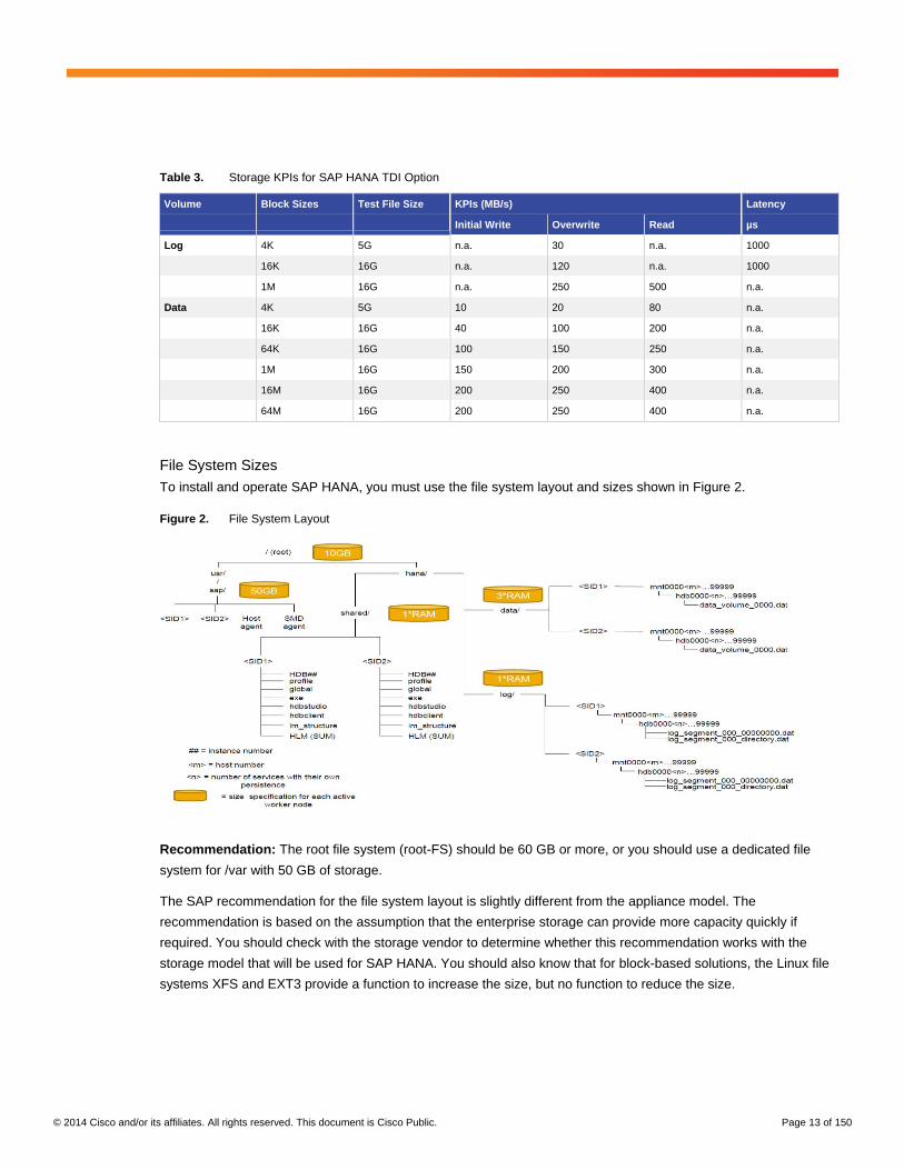
Table 3. Storage KPIs for SAP HANA TDI Option
Volume
Block Sizes
Test File Size
KPIs (MB/s) Latency
Initial Write Overwrite Read µs
Log 4K 5G n.a. 30 n.a. 1000
16K 16G n.a. 120 n.a. 1000
1M 16G n.a. 250 500 n.a.
Data 4K 5G 10 20 80 n.a.
16K 16G 40 100 200 n.a.
64K 16G 100 150 250 n.a.
1M 16G 150 200 300 n.a.
16M 16G 200 250 400 n.a.
64M 16G 200 250 400 n.a.
File System Sizes
To install and operate SAP HANA, you must use the file system layout and sizes shown in Figure 2.
Figure 2. File System Layout
Recommendation: The root file system (root-FS) should be 60 GB or more, or you should use a dedicated file
system for /var with 50 GB of storage.
The SAP recommendation for the file system layout is slightly different from the appliance model. The
recommendation is based on the assumption that the enterprise storage can provide more capacity quickly if
required. You should check with the storage vendor to determine whether this recommendation works with the
storage model that will be used for SAP HANA. You should also know that for block-based solutions, the Linux file
systems XFS and EXT3 provide a function to increase the size, but no function to reduce the size.

© 2014 Cisco and/or its affiliates. All rights reserved. This document is Cisco Public. Page 14 of 150
Scale-Up Solution
Here is a sample configuration for a scale-up solution with 512 GB of memory.
Root-FS: 50 GB
/usr/sap: 100 GB
/hana/log: 1x memory (512 GB)
/hana/data: 1x memory (512 GB)
Scale-Out Solution
Here is a sample configuration for a scale-out solution with 512 GB of memory per server.
For each server:
Root-FS: 50 GB
/usr/sap: 100 GB
/hana/shared: Number of nodes x 512 GB (2 + 0 configuration sample: 2 x 512 GB =
1024 GB)
For every active HANA node:
/hana/log/<SID>/mntXXXXX: 1x memory (512 GB)
/hana/data/<SID>/mntXXXXX: 1x memory (512 GB)
Log Volume with Intel Xeon Processor E7-x890v2 CPU
For solutions based on the Intel Xeon processor E7-x890v2, the size of the log volume has changed.
● Half of the server memory for systems with 256 GB of memory or less
● Minimum of 512 GB of the server memory for systems with 512 GB of memory or more
Operating System
The supported operating systems for SAP HANA are SLES or the specialized packaged distribution SLES for
SAP Applications. The exact version and service pack release are documented by SAP in the SAP HANA PAM.
As of November 2013, the supported versions are SLES 11 SP2, SLES 11 SP3, and SUSE Linux Enterprise
Server for SAP applications.
Boot Options
No boot option restrictions are defined, and the solution vendor can specify the best boot option, such as boot from
internal disks, SAN boot, or PXE boot, based on best practices.
High Availability
The scale-out solution must have no single point of failure. After failures in the components, the SAP HANA
database must still be operational and running. For automatic host failover, the proper implementation and
operation of the SAP HANA storage connector API must be used.
Hardware and software components should include the following:
● Internal storage: A RAID-based configuration is preferred
● External storage: Redundant data paths, dual controllers, and a RAID-based configuration is preferred.

© 2014 Cisco and/or its affiliates. All rights reserved. This document is Cisco Public. Page 15 of 150
● Fibre Channel switches: Two independent fabrics should be used for storage connectivity.
● Ethernet switches: Two or more independent switches should be used.
Cisco Solution for SAP HANA Scale-Out Design
This section provides an overview of solution design for an appliance-like SAP HANA scale-out implementation.
The initial solution design was developed to meet all the requirements from SAP for a SAP HANA scale-out
appliance. The term “appliance” is a bit misleading because this implementation is a preinstalled solution for SAP
HANA and not an appliance. SAP HANA 1.0 up to Service Pack 6 required that all hardware components, such as
server, network, and storage resources, must be dedicated to one single SAP HANA database.
The Cisco design developed for SAP HANA used the following components:
● Cisco Unified Computing System
◦ 2x Cisco UCS 6248UP 48-Port or 6296UP 96-Port Fabric Interconnects
◦ 1x to 5x Cisco UCS 5108 Blade Chassis
◦ 2x Cisco UCS 2204 Fabric Extenders connected with 4x 10 Gigabit Ethernet interfaces to
fabric interconnect
◦ 3x to 16x Cisco UCS B440 M2 High-Performance Blade Servers with 2x Cisco UCS Virtual Interface
Card (VIC) 1280
◦ Each server has 2x 10 Gigabit Ethernet dedicated bandwidth
● Cisco switches
◦ 2x Cisco Nexus® 5548 or 5596 Switch for 10 Gigabit Ethernet and Fibre Channel connectivity
◦ 2x Cisco Nexus 2224TP GE Fabric Extender to connect the devices that do not support 10
Gigabit Ethernet
● Storage
◦ EMC VNX5300 unified storage, with NFS for the OS and Fibre Channel for data files and log
◦ NetApp FAS3240 and FAS3250, with NFS for the OS, data files, and log
● Cisco UCS C-Series Rack Servers
◦ 2x Cisco UCS C220 M3 Rack Server to host the management virtual machines
◦ 1x SLES-based management server as VMware virtual machine
◦ 1x Microsoft Windows–based monitoring server as VMware virtual machine
● Cisco 2911 Integrated Services Router (ISR)
◦ Serial console access to all devices
◦ Optional Network Address Translation (NAT) configuration for Cisco Smart Call Home, Simple Network
Management Protocol (SNMP), and syslog

© 2014 Cisco and/or its affiliates. All rights reserved. This document is Cisco Public. Page 16 of 150
Note: The Cisco UCS C-Series servers, the management virtual machines, and the Cisco 2911 ISR are not part
of the validation and certification effort and do have not to implement the restrictions from SAP about changes.
Every VMware ESX version that is supported by the Cisco UCS C220 M3 can be installed. The Cisco UCS C220
M3 also can be integrated into a VMware vCenter domain. An NFS share can be mounted as data store, and files
can be moved from internal storage to external storage. The Cisco 2911 ISR can also be used for VPN access by
the Cisco Technical Assistance Center (TAC).
Because the VLAN groups feature was not available in Cisco UCS at the time the solution was designed, all LAN
and SAN traffic had to be forwarded to the Cisco Nexus 5500 platform switches. The integration into the data
center network was performed using access ports on the Cisco Nexus 5500 platform switches, what caused some
discussion about how the integration should be accomplished.
Because of the limited capabilities of SLES for handling multipath SAN devices, especially in case of SAP HANA
DT, PXE boot was used with the root file system on NFS. All required components are available, with Domain Host
Configuration Protocol (DHCP) and Trivial FTP (TFTP) server on the management server and NFS shares on the
storage systems (Figure 3).
Figure 3. Cisco Solution for SAP HANA Scale-Out Design
The operating systems for the SAP HANA nodes are located on a NFS share on the external storage and mounted
on the management server for easier administration. Cisco provides golden images to deploy the operating
systems for the SAP HANA nodes. The input for the golden images is the operating systems used in the lab for
testing and validation.

© 2014 Cisco and/or its affiliates. All rights reserved. This document is Cisco Public. Page 17 of 150
Cisco UCS Configuration
This document does not present the complete Cisco UCS configuration options. For example, this document does
not show how to configure administrative network access or how to configure MAC address, World Wide Node
(WWN) address, or IP address pools. The focus of this document is on configuring the system to run SAP HANA.
Some specific Cisco UCS configuration options are required to fulfill the requirements from SAP for SAP HANA.
Chassis Connection Options
For the Cisco UCS 2200 Series Fabric Extenders, two configuration options are available: pinning
and PortChannel.
Because every SAP HANA node will communicate with every other SAP HANA node with multiple I/O streams, the
PortChannel option provides the better features. However, there are also use cases in which only a few large I/O
streams are used, and for these the pinning option provides a more stable performance. Because communication
behavior can be different from use case to use case, SAP defined a single-stream network performance test as
part of the hardware validation tool (hwcct or hwval). To pass the hwval test, the pinning mode was used for the
Cisco solutions.
Chassis Connection in Pinning Mode
In the pinning mode, every VIC in a Cisco UCS B440 server is pinned to an uplink cable from the fabric extender
(or I/O module [IOM]) to the fabric interconnect based on the available number of uplinks. In most cases, the
chassis are connected with four 10 Gigabit Ethernet cables per IOM to the fabric interconnect. The chassis
backplane provides eight internal connections; a half-width blade can use one connection, and a full-width blade
can use two connections. Every connector is mapped to a VIC on the blade, and every VIC is represented by a
virtual network interface connection (vCON) in Cisco UCS Manager.
To run SAP HANA on an infrastructure with four uplinks per IOM, use Tables 4 and 5 to understand the pinning of
IOM uplink ports (P1 to P4) and vCON. This pinning information is used when the virtual network interface card
(vNIC) and virtual host bus adapter (vHBA) placement policy is defined.
Table 4. Cisco UCS 5108 Chassis with Eight Half-Width Blades
P1 - vCON1 P2 - vCON1
P3 - vCON1 P4 - vCON1
P1 - vCON1 P2 - vCON1
P3 - vCON1 P4 - vCON1
Table 5. Cisco UCS 5108 Chassis with Four Full-Width Blades
P1 - vCON1 P2 - vCON2
P3 - vCON1 P4 - vCON2
P1 - vCON1 P2 - vCON2
P3 - vCON1 P4 - vCON2
The best configuration found to pass the hwval test uses pinning mode and vNIC placement as follows:
● All servers running in slots 1 and 3 are configured to use vCON1 only.
● All servers running in slots 5 and 7 are configured to use vCON2 only.

© 2014 Cisco and/or its affiliates. All rights reserved. This document is Cisco Public. Page 18 of 150
With this configuration, the single-stream test shows a result of 9.5-Gbps throughput.
Choose Equipment > Global Policies, and for Chassis/FEX Discovery Policy, select None for Link Grouping
Preference to use the pinning mode (Figure 4).
Figure 4. Chassis Discovery Policy
In the pinning mode example in Figure 5, nothing is listed in the Port Channel column.
Figure 5. IOM Fabric Ports with Pinning Mode
In the PortChannel example in Figure 6, the Port Channel column lists the PortChannel used.
Figure 6. IOM Fabric Ports with Port Channel Mode
© 2014 Cisco and/or its affiliates. All rights reserved. This document is Cisco Public. Page 19 of 150
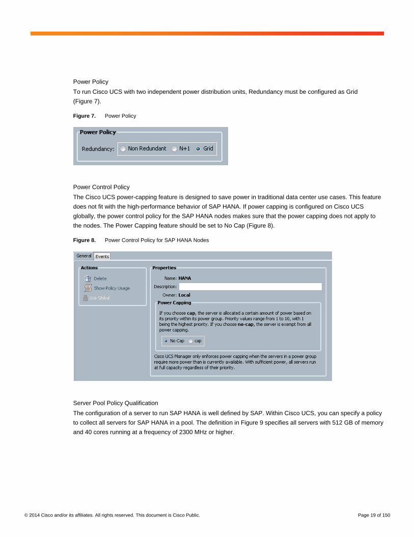
Power Policy
To run Cisco UCS with two independent power distribution units, Redundancy must be configured as Grid
(Figure 7).
Figure 7. Power Policy
Power Control Policy
The Cisco UCS power-capping feature is designed to save power in traditional data center use cases. This feature
does not fit with the high-performance behavior of SAP HANA. If power capping is configured on Cisco UCS
globally, the power control policy for the SAP HANA nodes makes sure that the power capping does not apply to
the nodes. The Power Capping feature should be set to No Cap (Figure 8).
Figure 8. Power Control Policy for SAP HANA Nodes
Server Pool Policy Qualification
The configuration of a server to run SAP HANA is well defined by SAP. Within Cisco UCS, you can specify a policy
to collect all servers for SAP HANA in a pool. The definition in Figure 9 specifies all servers with 512 GB of memory
and 40 cores running at a frequency of 2300 MHz or higher.
© 2014 Cisco and/or its affiliates. All rights reserved. This document is Cisco Public. Page 20 of 150
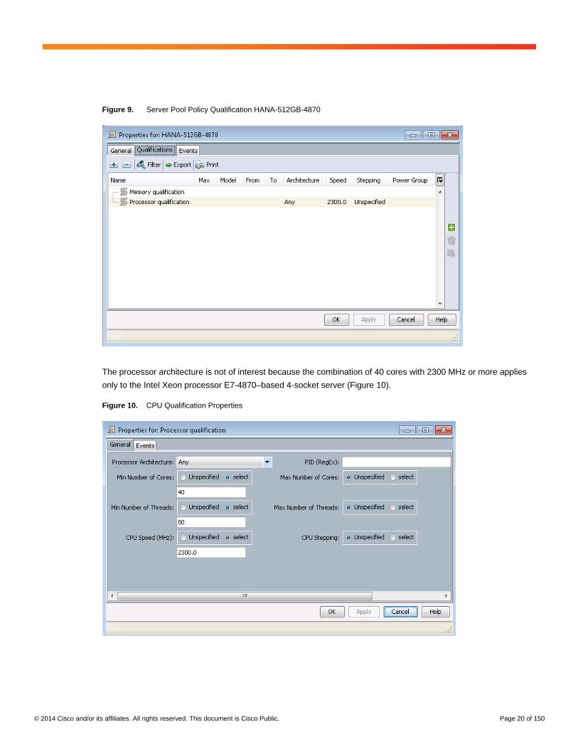
Figure 9. Server Pool Policy Qualification HANA-512GB-4870
The processor architecture is not of interest because the combination of 40 cores with 2300 MHz or more applies
only to the Intel Xeon processor E7-4870–based 4-socket server (Figure 10).
Figure 10. CPU Qualification Properties

© 2014 Cisco and/or its affiliates. All rights reserved. This document is Cisco Public. Page 21 of 150
The capacity is defined as exactly 512 GB of memory (Figure 11).
Figure 11. Memory Qualification Properties
Figure 12 shows the server pool for all the servers.
Figure 12. Server Pool

© 2014 Cisco and/or its affiliates. All rights reserved. This document is Cisco Public. Page 22 of 150
Server Pool Policy
The server pool for the SAP HANA nodes and the qualification policy is also defined. In this case, the two
definitions are mapped together (Figure 13).
Figure 13. Server Pool Policy HANA-512GB-4870
As a result, all servers with the specified qualification are now available in the server pool (Figure 14).
Figure 14. List of Servers in Server Pool HANA-512GB-4870

© 2014 Cisco and/or its affiliates. All rights reserved. This document is Cisco Public. Page 23 of 150
BIOS Policy
To get best performance for SAP HANA, you must configure the server BIOS accordantly. On the Main tab, the
only change made was to disable Quiet Boot to see details in the posting (Figure 15).
Figure 15. BIOS Policy Main Settings
For SAP HANA, SAP also recommends disabling all Processor C states (Figure 16). This configuration will force
the CPU to stay on the maximum frequency and allow SAP HANA to run with the best performance.
Figure 16. BIOS Policy: Advanced > Processor
© 2014 Cisco and/or its affiliates. All rights reserved. This document is Cisco Public. Page 24 of 150
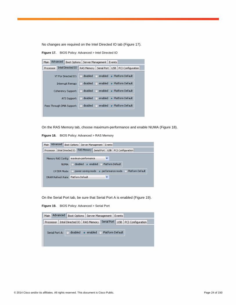
No changes are required on the Intel Directed IO tab (Figure 17).
Figure 17. BIOS Policy: Advanced > Intel Directed IO
On the RAS Memory tab, choose maximum-performance and enable NUMA (Figure 18).
Figure 18. BIOS Policy: Advanced > RAS Memory
On the Serial Port tab, be sure that Serial Port A is enabled (Figure 19).
Figure 19. BIOS Policy: Advanced > Serial Port
© 2014 Cisco and/or its affiliates. All rights reserved. This document is Cisco Public. Page 25 of 150
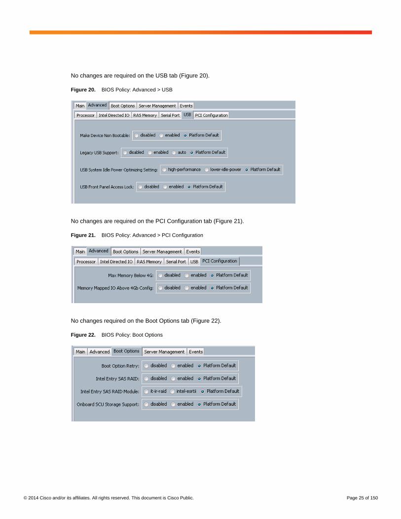
No changes are required on the USB tab (Figure 20).
Figure 20. BIOS Policy: Advanced > USB
No changes are required on the PCI Configuration tab (Figure 21).
Figure 21. BIOS Policy: Advanced > PCI Configuration
No changes required on the Boot Options tab (Figure 22).
Figure 22. BIOS Policy: Boot Options
© 2014 Cisco and/or its affiliates. All rights reserved. This document is Cisco Public. Page 26 of 150
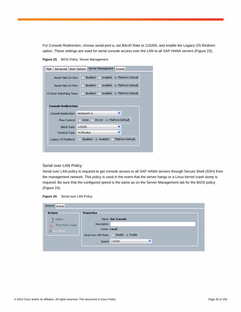
For Console Redirection, choose serial-port-a, set BAUD Rate to 115200, and enable the Legacy OS Redirect
option. These settings are used for serial console access over the LAN to all SAP HANA servers (Figure 23).
Figure 23. BIOS Policy: Server Management
Serial over LAN Policy
Serial over LAN policy is required to get console access to all SAP HANA servers through Secure Shell (SSH) from
the management network. This policy is used in the event that the server hangs or a Linux kernel crash dump is
required. Be sure that the configured speed is the same as on the Server Management tab for the BIOS policy
(Figure 24).
Figure 24. Serial over LAN Policy

© 2014 Cisco and/or its affiliates. All rights reserved. This document is Cisco Public. Page 27 of 150
Maintenance Policies
Cisco recommends defining a maintenance policy with Reboot Policy set to User Ack for the SAP HANA server
(Figure 25). This policy helps ensure that a configuration change in Cisco UCS does not automatically force all
SAP HANA servers to reboot. The administrator has to acknowledge the reboot for the servers changed in Cisco
UCS; otherwise, the configuration change will take effect when the server reboots through an OS command.
Figure 25. Maintenance Policy
© 2014 Cisco and/or its affiliates. All rights reserved. This document is Cisco Public. Page 28 of 150
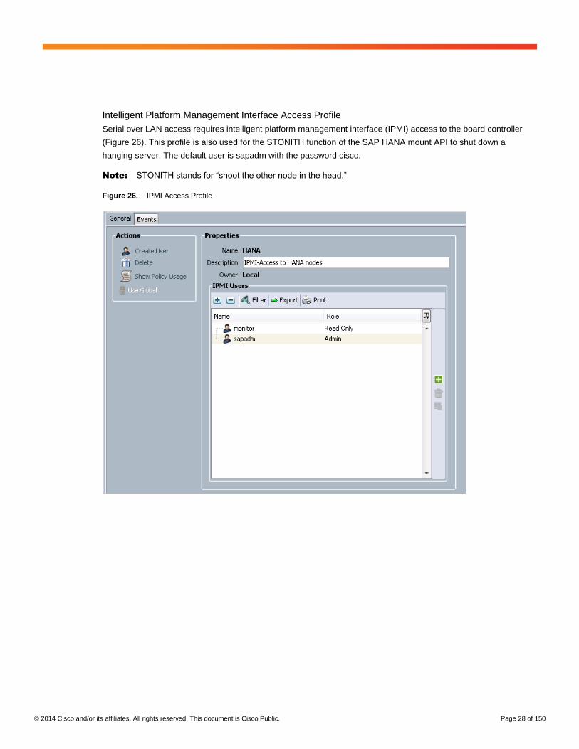
Intelligent Platform Management Interface Access Profile
Serial over LAN access requires intelligent platform management interface (IPMI) access to the board controller
(Figure 26). This profile is also used for the STONITH function of the SAP HANA mount API to shut down a
hanging server. The default user is sapadm with the password cisco.
Note: STONITH stands for “shoot the other node in the head.”
Figure 26. IPMI Access Profile

© 2014 Cisco and/or its affiliates. All rights reserved. This document is Cisco Public. Page 29 of 150
Adapter Policy Configuration
Figure 27 shows newly created Ethernet adapter policy Linux-B440 with Receive-Side Scaling (RSS), Receive
Queues, and Interrupts values defined. This policy must be used for the SAP HANA internal network to provide the
best network performance with SLES 11.
Figure 27. Adapter Policy Linux-B440
© 2014 Cisco and/or its affiliates. All rights reserved. This document is Cisco Public. Page 30 of 150
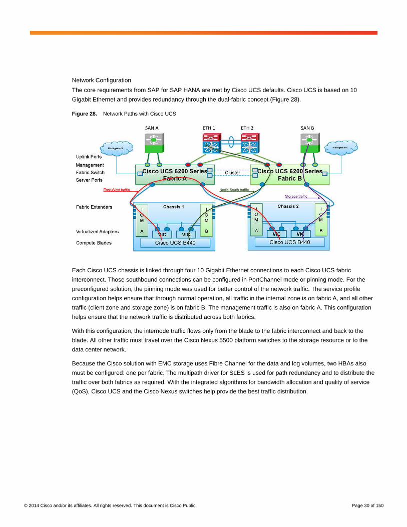
Network Configuration
The core requirements from SAP for SAP HANA are met by Cisco UCS defaults. Cisco UCS is based on 10
Gigabit Ethernet and provides redundancy through the dual-fabric concept (Figure 28).
Figure 28. Network Paths with Cisco UCS
Each Cisco UCS chassis is linked through four 10 Gigabit Ethernet connections to each Cisco UCS fabric
interconnect. Those southbound connections can be configured in PortChannel mode or pinning mode. For the
preconfigured solution, the pinning mode was used for better control of the network traffic. The service profile
configuration helps ensure that through normal operation, all traffic in the internal zone is on fabric A, and all other
traffic (client zone and storage zone) is on fabric B. The management traffic is also on fabric A. This configuration
helps ensure that the network traffic is distributed across both fabrics.
With this configuration, the internode traffic flows only from the blade to the fabric interconnect and back to the
blade. All other traffic must travel over the Cisco Nexus 5500 platform switches to the storage resource or to the
data center network.
Because the Cisco solution with EMC storage uses Fibre Channel for the data and log volumes, two HBAs also
must be configured: one per fabric. The multipath driver for SLES is used for path redundancy and to distribute the
traffic over both fabrics as required. With the integrated algorithms for bandwidth allocation and quality of service
(QoS), Cisco UCS and the Cisco Nexus switches help provide the best traffic distribution.

© 2014 Cisco and/or its affiliates. All rights reserved. This document is Cisco Public. Page 31 of 150
LAN Tab Configuration
In Cisco UCS, all network types for a SAP HANA system are defined in VLANs. In the first-generation Cisco
solution, VLAN definition included only four networks: Admin, Access, NFS-IPv6 (for SAP HANA data and log
volumes), and Storage (for the NFS root). To run multiple SAP HANA systems, four areas (system IDs [SIDs]) were
predefined: T01 to T04 (Figure 29).
Figure 29. VLAN Definition in Cisco UCS (Old)

© 2014 Cisco and/or its affiliates. All rights reserved. This document is Cisco Public. Page 32 of 150
The second-generation Cisco UCS solution follows the new network design from SAP, which includes seven SAP
HANA–related networks plus two infrastructure-related networks (Figure 30). The VLAN IDs can be changed if
required to match the VLAN IDs in the data center network: for example, ID 1017 used for backup should match
the configured VLAN ID at the data center network switches.
Figure 30. VLAN Definition in Cisco UCS (New)
© 2014 Cisco and/or its affiliates. All rights reserved. This document is Cisco Public. Page 33 of 150
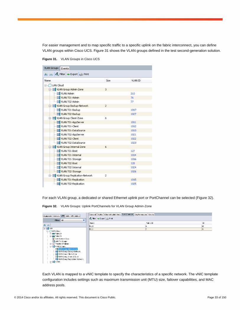
For easier management and to map specific traffic to a specific uplink on the fabric interconnect, you can define
VLAN groups within Cisco UCS. Figure 31 shows the VLAN groups defined in the test second-generation solution.
Figure 31. VLAN Groups in Cisco UCS
For each VLAN group, a dedicated or shared Ethernet uplink port or PortChannel can be selected (Figure 32).
Figure 32. VLAN Groups: Uplink PortChannels for VLAN Group Admin-Zone
Each VLAN is mapped to a vNIC template to specify the characteristics of a specific network. The vNIC template
configuration includes settings such as maximum transmission unit (MTU) size, failover capabilities, and MAC
address pools.

© 2014 Cisco and/or its affiliates. All rights reserved. This document is Cisco Public. Page 34 of 150
In the first version of the Cisco solution for SAP HANA, only four vNICs are defined (Figure 33).
Figure 33. vNIC Templates (Old)
In the second version of the Cisco solution for SAP HANA, all VLAN IDs for SAP HANA are mapped (Figure 34).
Figure 34. vNIC Templates (New)
© 2014 Cisco and/or its affiliates. All rights reserved. This document is Cisco Public. Page 35 of 150
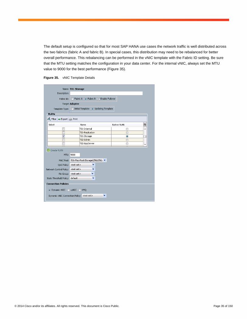
The default setup is configured so that for most SAP HANA use cases the network traffic is well distributed across
the two fabrics (fabric A and fabric B). In special cases, this distribution may need to be rebalanced for better
overall performance. This rebalancing can be performed in the vNIC template with the Fabric ID setting. Be sure
that the MTU setting matches the configuration in your data center. For the internal vNIC, always set the MTU
value to 9000 for the best performance (Figure 35).
Figure 35. vNIC Template Details

© 2014 Cisco and/or its affiliates. All rights reserved. This document is Cisco Public. Page 36 of 150
SAN Access Configuration
For SAN access, you must configure vHBAs. A best practice is to configure vHBA templates: one for fabric A and
one for fabric B (Figure 36).
Figure 36. Create vHBA Template
Service Profile Template Configuration
Now that all LAN and SAN access configurations and all policies relevant to SAP HANA are defined, a service
profile template can be configured.
© 2014 Cisco and/or its affiliates. All rights reserved. This document is Cisco Public. Page 37 of 150
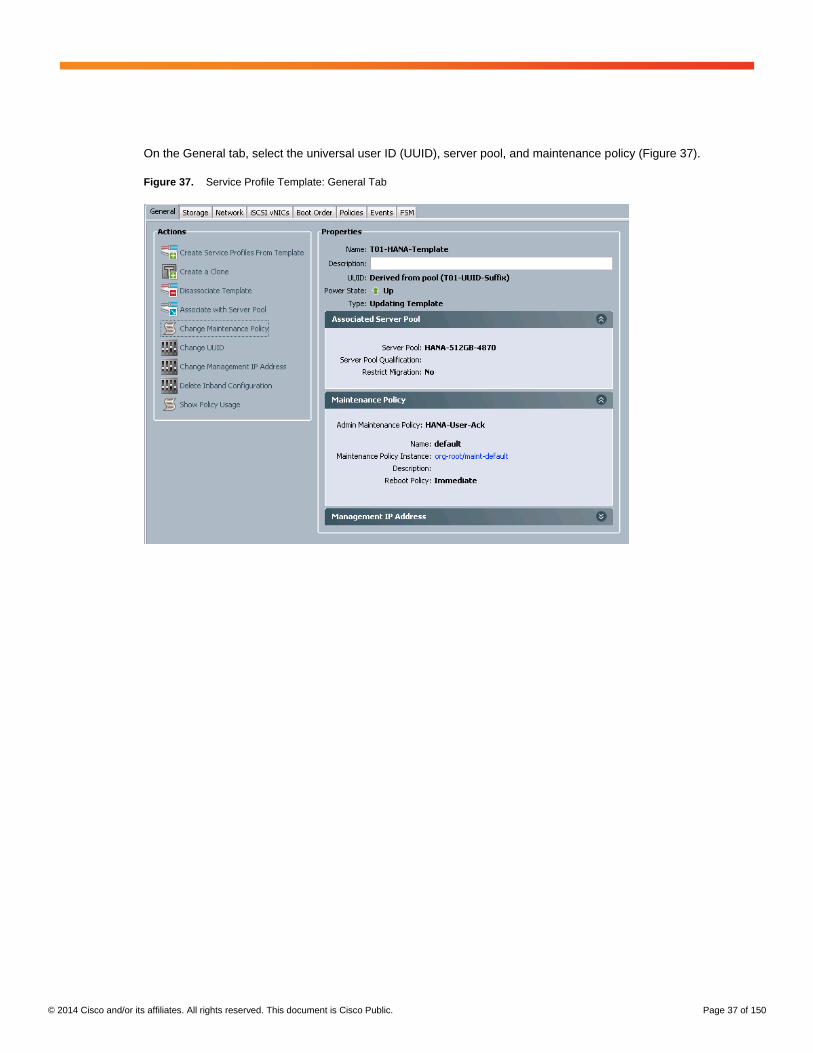
On the General tab, select the universal user ID (UUID), server pool, and maintenance policy (Figure 37).
Figure 37. Service Profile Template: General Tab

© 2014 Cisco and/or its affiliates. All rights reserved. This document is Cisco Public. Page 38 of 150
On the Storage tab, define World Wide Node Name (WWNN) configuration and the vHBAs based on the vHBA
templates (Figure 38).
Figure 38. Service Profile Template: Storage Tab (New)

© 2014 Cisco and/or its affiliates. All rights reserved. This document is Cisco Public. Page 39 of 150
On the Network tab, define the required vNICs based on the vNIC templates. To map the pinning at the IOM layer,
you must manually configure the vNIC and vHBA placement (Figure 39).
Figure 39. Service Profile Template: Network Tab (Old)
In the Actions pane, select Modify vNIC/vHBA Placement. For the service profile template used for all servers in
slots 1 and 3, assign all vNICs to vCON1 (Figure 40).
Figure 40. vNIC and vHBA Placement for Slots 1 and 3 (Old)

© 2014 Cisco and/or its affiliates. All rights reserved. This document is Cisco Public. Page 40 of 150
For the service profile template used for all servers in slots 5 and 7, assign all vNICs to vCON2 (Figure 41).
Figure 41. vNIC and vHBA Placement for Slots 5 and 7 (Old)
On the Boot Order tab, use PXE boot for the Cisco solution (Figure 42).
Figure 42. Service Profile Template: Boot Order Sample for PXE Boot

© 2014 Cisco and/or its affiliates. All rights reserved. This document is Cisco Public. Page 41 of 150
On the Policies tab, all the definitions already created are selected (Figures 43 and 44).
Figure 43. Service Profile Template: Policies Tab (Part 1)
Figure 44. Service Profile Template: Policies Tab (Part 2)
In the Cisco solution, nothing is configured on the iSCSI vNICs tab.

© 2014 Cisco and/or its affiliates. All rights reserved. This document is Cisco Public. Page 42 of 150
Service Profile Deployment
The basic settings are defined and captured in the service profile template for SAP HANA nodes. To deploy new
SAP HANA nodes, the only step that is required in Cisco UCS is to create service profiles from the specified
service profile template (Figure 45).
Figure 45. Service Profile Template: Before Service Profiles Are Created
Click Create Service Profile from Template, and a new window will appear. In this window, specify the service
profile name prefix, the starting number, and the number of service profiles to create (Figure 46).
Figure 46. Create Service Profile From Template
© 2014 Cisco and/or its affiliates. All rights reserved. This document is Cisco Public. Page 43 of 150
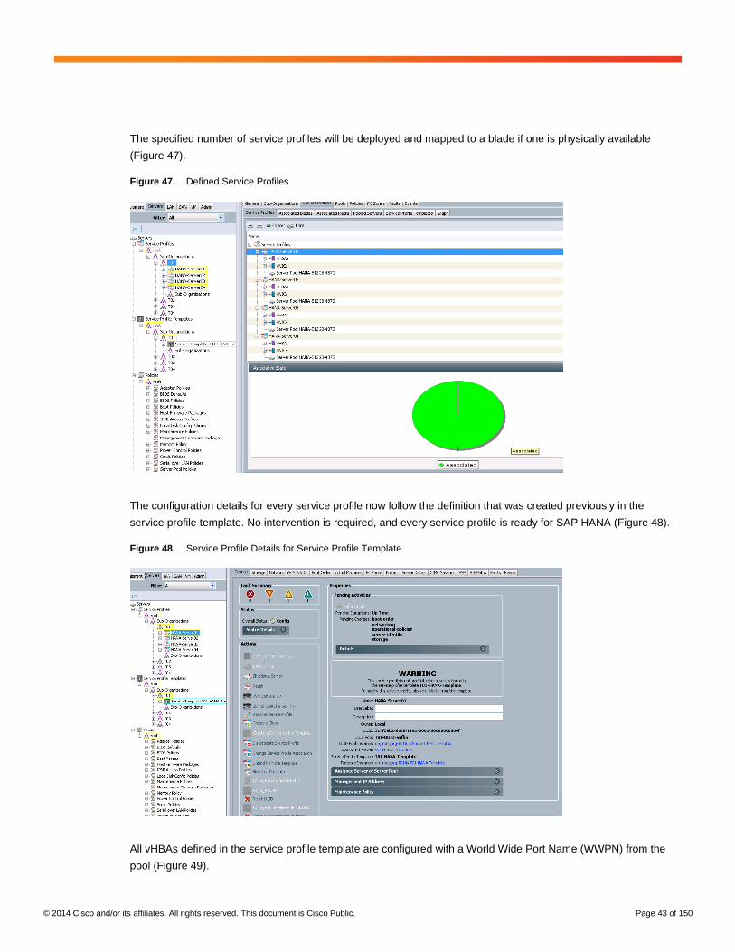
The specified number of service profiles will be deployed and mapped to a blade if one is physically available
(Figure 47).
Figure 47. Defined Service Profiles
The configuration details for every service profile now follow the definition that was created previously in the
service profile template. No intervention is required, and every service profile is ready for SAP HANA (Figure 48).
Figure 48. Service Profile Details for Service Profile Template
All vHBAs defined in the service profile template are configured with a World Wide Port Name (WWPN) from the
pool (Figure 49).

© 2014 Cisco and/or its affiliates. All rights reserved. This document is Cisco Public. Page 44 of 150
Figure 49. Service Profile: Storage Tab
All vNICs defined in the service profile template are configured with a MAC address from the pools (Figure 50).
Figure 50. Service Profile: Network Tab
© 2014 Cisco and/or its affiliates. All rights reserved. This document is Cisco Public. Page 45 of 150
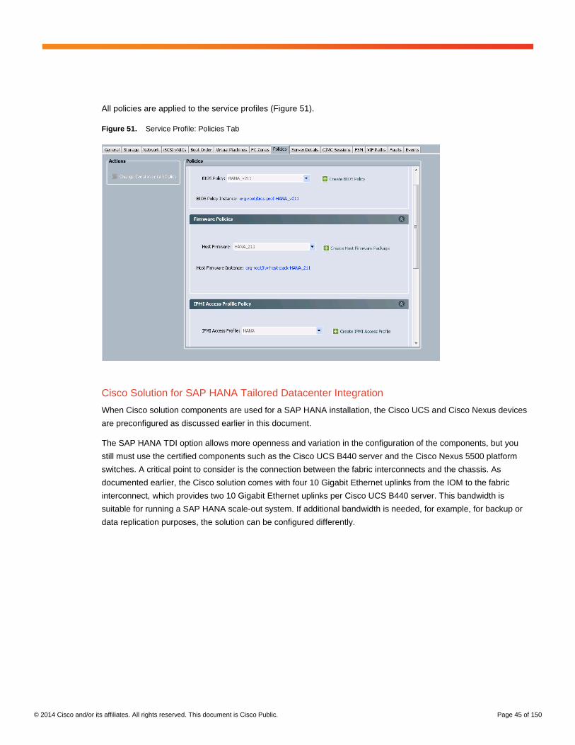
All policies are applied to the service profiles (Figure 51).
Figure 51. Service Profile: Policies Tab
Cisco Solution for SAP HANA Tailored Datacenter Integration
When Cisco solution components are used for a SAP HANA installation, the Cisco UCS and Cisco Nexus devices
are preconfigured as discussed earlier in this document.
The SAP HANA TDI option allows more openness and variation in the configuration of the components, but you
still must use the certified components such as the Cisco UCS B440 server and the Cisco Nexus 5500 platform
switches. A critical point to consider is the connection between the fabric interconnects and the chassis. As
documented earlier, the Cisco solution comes with four 10 Gigabit Ethernet uplinks from the IOM to the fabric
interconnect, which provides two 10 Gigabit Ethernet uplinks per Cisco UCS B440 server. This bandwidth is
suitable for running a SAP HANA scale-out system. If additional bandwidth is needed, for example, for backup or
data replication purposes, the solution can be configured differently.

© 2014 Cisco and/or its affiliates. All rights reserved. This document is Cisco Public. Page 46 of 150
PortChannel Connection
The first step for implementing a Cisco solution for SAP HANA TDI is a software configuration change. Change the
chassis discovery policy from None to Port Channel (Figure 52).
Figure 52. Chassis Discovery Policy
Alternatively, if Cisco UCS is not used exclusively for SAP HANA, this configuration can be changed on a per
chassis basis (Figure 53).
Figure 53. Chassis Connectivity Policy
This simple change can have a huge impact on the SAP HANA solution. The details of the pinning mode, which is
used if None is selected, are discussed earlier in this document, in the “Chassis Connection Options” section.
Chassis Connection in PortChannel Mode
Because SAP is using single-stream bidirectional network communication between SAP HANA nodes, a
PortChannel-based configuration of Cisco UCS will not always have the best performance. With the implemented
hashing algorithm on the IOM and fabric interconnect, the outbound traffic (IOM to fabric interconnect) as well as
the inbound traffic (fabric interconnect to IOM) can travel over the same cable. Therefore, for a unidirectional test,
the results will be greater than or equal to 9.5 Gigabit Ethernet outbound, and greater than or equal to 9.5 Gigabit
Ethernet inbound. A bidirectional test has twice the outbound and twice the inbound traffic on the same cable, and
the results will be 4.5 Gigabit Ethernet or less per direction.
© 2014 Cisco and/or its affiliates. All rights reserved. This document is Cisco Public. Page 47 of 150
For a SAP HANA system, the PortChannel option provides some benefits because a single node can use eight 10
Gigabit Ethernet connections in burst mode to communicate with other nodes and the storage or the application
server; the pinning mode limits communication to two 10 Gigabit Ethernet connections.
The PortChannel mode is preferred in cases in which Cisco UCS is used as a shared platform running SAP HANA
and other applications at the same time. In such cases, the following server distribution options are recommended:
● Use one server per chassis for SAP HANA and the others for applications other than SAP HANA.
● Use server 1 and 7 per chassis for SAP HANA and the others for applications other than SAP HANA.
● Use all servers per chassis for SAP HANA, with each server used for a different SID.
● Use all servers per chassis for a single SAP HANA SID.
The use of PortChannel mode also simplifies the vNIC and service profile template configuration.
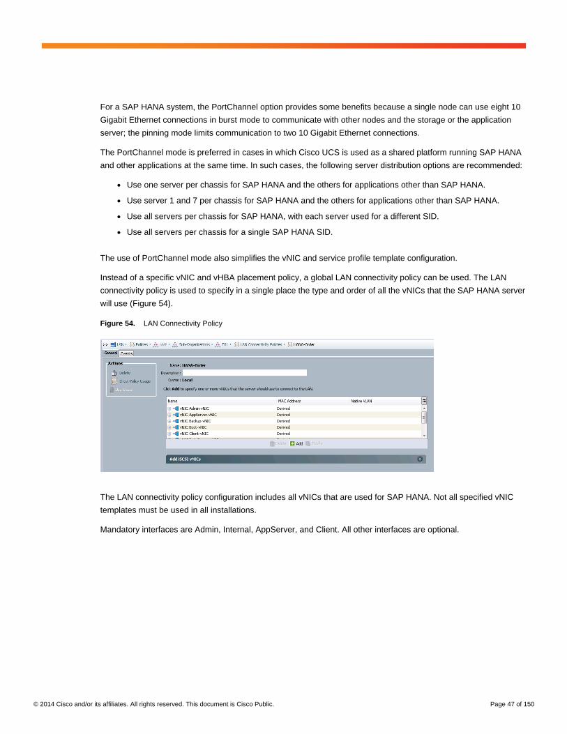
Instead of a specific vNIC and vHBA placement policy, a global LAN connectivity policy can be used. The LAN
connectivity policy is used to specify in a single place the type and order of all the vNICs that the SAP HANA server
will use (Figure 54).
Figure 54. LAN Connectivity Policy
The LAN connectivity policy configuration includes all vNICs that are used for SAP HANA. Not all specified vNIC
templates must be used in all installations.
Mandatory interfaces are Admin, Internal, AppServer, and Client. All other interfaces are optional.
© 2014 Cisco and/or its affiliates. All rights reserved. This document is Cisco Public. Page 48 of 150
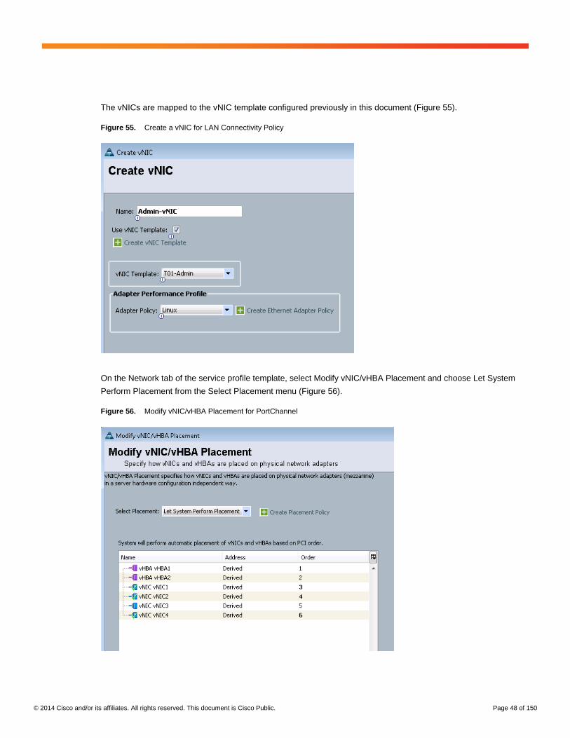
The vNICs are mapped to the vNIC template configured previously in this document (Figure 55).
Figure 55. Create a vNIC for LAN Connectivity Policy
On the Network tab of the service profile template, select Modify vNIC/vHBA Placement and choose Let System
Perform Placement from the Select Placement menu (Figure 56).
Figure 56. Modify vNIC/vHBA Placement for PortChannel
© 2014 Cisco and/or its affiliates. All rights reserved. This document is Cisco Public. Page 49 of 150
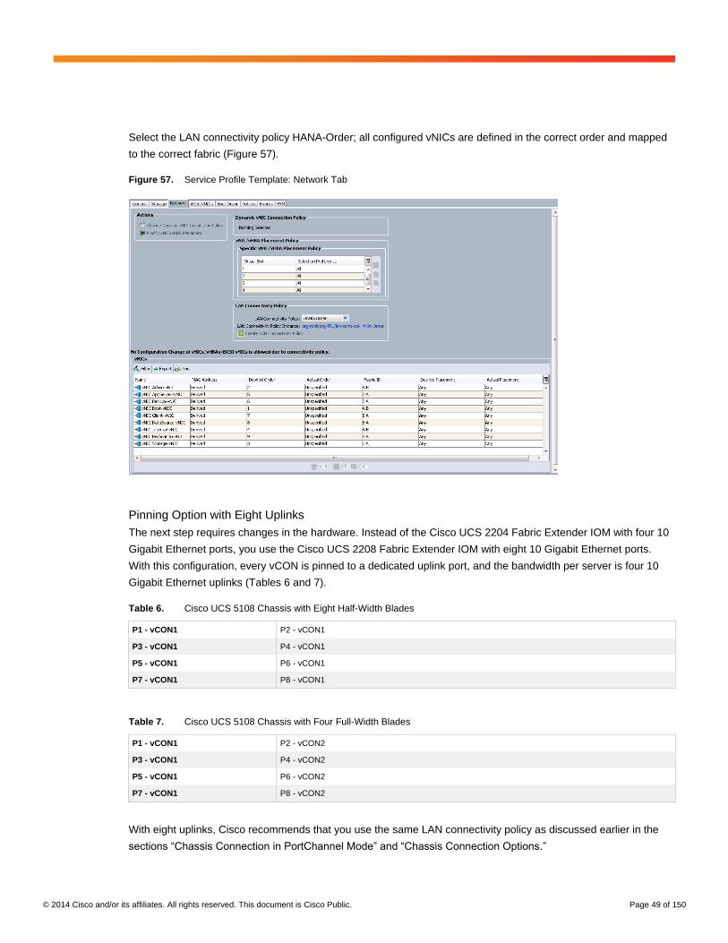
Select the LAN connectivity policy HANA-Order; all configured vNICs are defined in the correct order and mapped
to the correct fabric (Figure 57).
Figure 57. Service Profile Template: Network Tab
Pinning Option with Eight Uplinks
The next step requires changes in the hardware. Instead of the Cisco UCS 2204 Fabric Extender IOM with four 10
Gigabit Ethernet ports, you use the Cisco UCS 2208 Fabric Extender IOM with eight 10 Gigabit Ethernet ports.
With this configuration, every vCON is pinned to a dedicated uplink port, and the bandwidth per server is four 10
Gigabit Ethernet uplinks (Tables 6 and 7).
Table 6. Cisco UCS 5108 Chassis with Eight Half-Width Blades
P1 - vCON1 P2 - vCON1
P3 - vCON1 P4 - vCON1
P5 - vCON1 P6 - vCON1
P7 - vCON1 P8 - vCON1
Table 7. Cisco UCS 5108 Chassis with Four Full-Width Blades
P1 - vCON1 P2 - vCON2
P3 - vCON1 P4 - vCON2
P5 - vCON1 P6 - vCON2
P7 - vCON1 P8 - vCON2
With eight uplinks, Cisco recommends that you use the same LAN connectivity policy as discussed earlier in the
sections “Chassis Connection in PortChannel Mode” and “Chassis Connection Options.”

© 2014 Cisco and/or its affiliates. All rights reserved. This document is Cisco Public. Page 50 of 150
Storage Connectivity Options
The next step is to set the storage connectivity option that will be used for this installation. The most common
connectivity options are shown here. The boot option and the SAP HANA configuration depend on the selection
you make.
Fibre Channel Storage Options
Before Fibre Channel storage can be used, the unified ports on the fabric interconnects must be changed from
Ethernet to Fibre Channel (Figure 58).
Figure 58. Fabric Interconnect: Configure Unified Ports

© 2014 Cisco and/or its affiliates. All rights reserved. This document is Cisco Public. Page 51 of 150
If an expansion module is installed, a best practice is to use the fixed module ports as server ports or Ethernet
uplink ports (Figure 59).
Figure 59. Unified Ports: Configure Fixed Module Ports
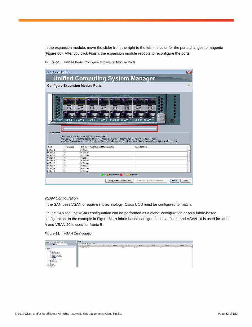
© 2014 Cisco and/or its affiliates. All rights reserved. This document is Cisco Public. Page 52 of 150
In the expansion module, move the slider from the right to the left; the color for the ports changes to magenta
(Figure 60). After you click Finish, the expansion module reboots to reconfigure the ports.
Figure 60. Unified Ports: Configure Expansion Module Ports
VSAN Configuration
If the SAN uses VSAN or equivalent technology, Cisco UCS must be configured to match.
On the SAN tab, the VSAN configuration can be performed as a global configuration or as a fabric-based
configuration. In the example in Figure 61, a fabric-based configuration is defined, and VSAN 10 is used for fabric
A and VSAN 20 is used for fabric B.
Figure 61. VSAN Configuration

© 2014 Cisco and/or its affiliates. All rights reserved. This document is Cisco Public. Page 53 of 150
If a Fibre Channel PortChannel is not used, each interface must be mapped to the correct VSAN (Figure 62).
Figure 62. Fibre Channel Port Details
If a Fibre Channel PortChannel is used, the VSAN mapping is part of the FC Port Channel configuration
(Figure 63).
Figure 63. Fibre Channel PortChannel Details
If the solution uses internal Cisco Nexus 5500 platform switches to attach the Fibre Channel storage, the VSAN
configuration must match the configuration in Cisco UCS, and the zoning must be based on global best practices.
An example of a Cisco Nexus 5500 platform configuration (based on NX55XX-A) is shown here.
Show the defined VSAN on the Cisco Nexus switch:
NX55XX-A# show vsan
vsan 1 information
name:VSAN0001 state:active
interoperability mode:default
loadbalancing:src-id/dst-id/oxid
operational state:down
vsan 10 information
name:VSAN0010 state:active
interoperability mode:default
loadbalancing:src-id/dst-id/oxid
operational state:up
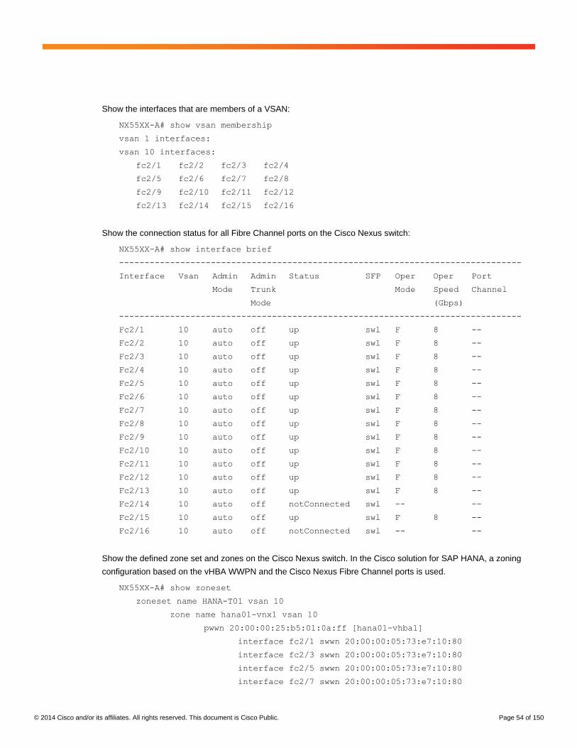
© 2014 Cisco and/or its affiliates. All rights reserved. This document is Cisco Public. Page 54 of 150
Show the interfaces that are members of a VSAN:
NX55XX-A# show vsan membership
vsan 1 interfaces:
vsan 10 interfaces:
fc2/1 fc2/2 fc2/3 fc2/4
fc2/5 fc2/6 fc2/7 fc2/8
fc2/9 fc2/10 fc2/11 fc2/12
fc2/13 fc2/14 fc2/15 fc2/16
Show the connection status for all Fibre Channel ports on the Cisco Nexus switch:
NX55XX-A# show interface brief
-------------------------------------------------------------------------------
Interface Vsan Admin Admin Status SFP Oper Oper Port
Mode Trunk Mode Speed Channel
Mode (Gbps)
-------------------------------------------------------------------------------
Fc2/1 10 auto off up swl F 8 --
Fc2/2 10 auto off up swl F 8 --
Fc2/3 10 auto off up swl F 8 --
Fc2/4 10 auto off up swl F 8 --
Fc2/5 10 auto off up swl F 8 --
Fc2/6 10 auto off up swl F 8 --
Fc2/7 10 auto off up swl F 8 --
Fc2/8 10 auto off up swl F 8 --
Fc2/9 10 auto off up swl F 8 --
Fc2/10 10 auto off up swl F 8 --
Fc2/11 10 auto off up swl F 8 --
Fc2/12 10 auto off up swl F 8 --
Fc2/13 10 auto off up swl F 8 --
Fc2/14 10 auto off notConnected swl -- --
Fc2/15 10 auto off up swl F 8 --
Fc2/16 10 auto off notConnected swl -- --
Show the defined zone set and zones on the Cisco Nexus switch. In the Cisco solution for SAP HANA, a zoning
configuration based on the vHBA WWPN and the Cisco Nexus Fibre Channel ports is used.
NX55XX-A# show zoneset
zoneset name HANA-T01 vsan 10
zone name hana01-vnx1 vsan 10
pwwn 20:00:00:25:b5:01:0a:ff [hana01-vhba1]
interface fc2/1 swwn 20:00:00:05:73:e7:10:80
interface fc2/3 swwn 20:00:00:05:73:e7:10:80
interface fc2/5 swwn 20:00:00:05:73:e7:10:80
interface fc2/7 swwn 20:00:00:05:73:e7:10:80
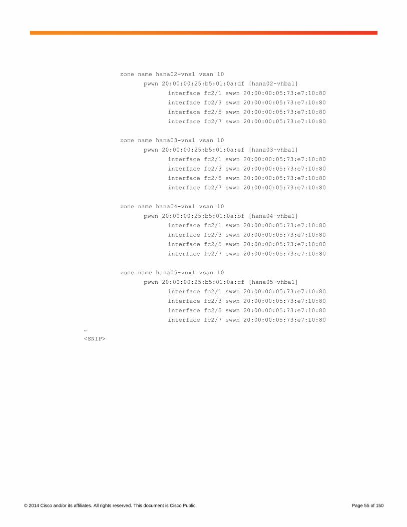
© 2014 Cisco and/or its affiliates. All rights reserved. This document is Cisco Public. Page 55 of 150
zone name hana02-vnx1 vsan 10
pwwn 20:00:00:25:b5:01:0a:df [hana02-vhba1]
interface fc2/1 swwn 20:00:00:05:73:e7:10:80
interface fc2/3 swwn 20:00:00:05:73:e7:10:80
interface fc2/5 swwn 20:00:00:05:73:e7:10:80
interface fc2/7 swwn 20:00:00:05:73:e7:10:80
zone name hana03-vnx1 vsan 10
pwwn 20:00:00:25:b5:01:0a:ef [hana03-vhba1]
interface fc2/1 swwn 20:00:00:05:73:e7:10:80
interface fc2/3 swwn 20:00:00:05:73:e7:10:80
interface fc2/5 swwn 20:00:00:05:73:e7:10:80
interface fc2/7 swwn 20:00:00:05:73:e7:10:80
zone name hana04-vnx1 vsan 10
pwwn 20:00:00:25:b5:01:0a:bf [hana04-vhba1]
interface fc2/1 swwn 20:00:00:05:73:e7:10:80
interface fc2/3 swwn 20:00:00:05:73:e7:10:80
interface fc2/5 swwn 20:00:00:05:73:e7:10:80
interface fc2/7 swwn 20:00:00:05:73:e7:10:80
zone name hana05-vnx1 vsan 10
pwwn 20:00:00:25:b5:01:0a:cf [hana05-vhba1]
interface fc2/1 swwn 20:00:00:05:73:e7:10:80
interface fc2/3 swwn 20:00:00:05:73:e7:10:80
interface fc2/5 swwn 20:00:00:05:73:e7:10:80
interface fc2/7 swwn 20:00:00:05:73:e7:10:80
…
<SNIP>

© 2014 Cisco and/or its affiliates. All rights reserved. This document is Cisco Public. Page 56 of 150
SAN-Based Fibre Channel Storage
SAN-based Fibre Channel storage is the most common option for connecting enterprise storage systems from
different storage vendors to Cisco UCS (Figure 64). Check the Cisco UCS Hardware Compatibility Matrix to
determine whether the storage model is supported.
Figure 64. SAN-Based Fibre Channel Storage
The fabric interconnects must be configured using FC Mode End Host to work with Fibre Channel switches from
different vendors. The SAN zoning must be implemented on the SAN switches.
Note: If internal Cisco Nexus switches are used to connect the storage device, the Fibre Channel configuration
should work without any changes.
Note: To connect Cisco UCS to the SAN switches, N-Port ID Virtualization (NPIV) support must be enabled on
all SAN devices. If NPIV is enabled and the VSAN configuration in Cisco UCS maps the configuration in the SAN,
the cables can be plugged in.

© 2014 Cisco and/or its affiliates. All rights reserved. This document is Cisco Public. Page 57 of 150
To verify that everything is configured correctly, select the fabric interconnect General tab (Figure 65).
Figure 65. Fabric Interconnect Details
Check the Fibre Channel port details to make sure that the correct VSAN is selected and that the Overall Status
field for the port displays Up (Figure 66).
Figure 66. Fibre Channel Port Details
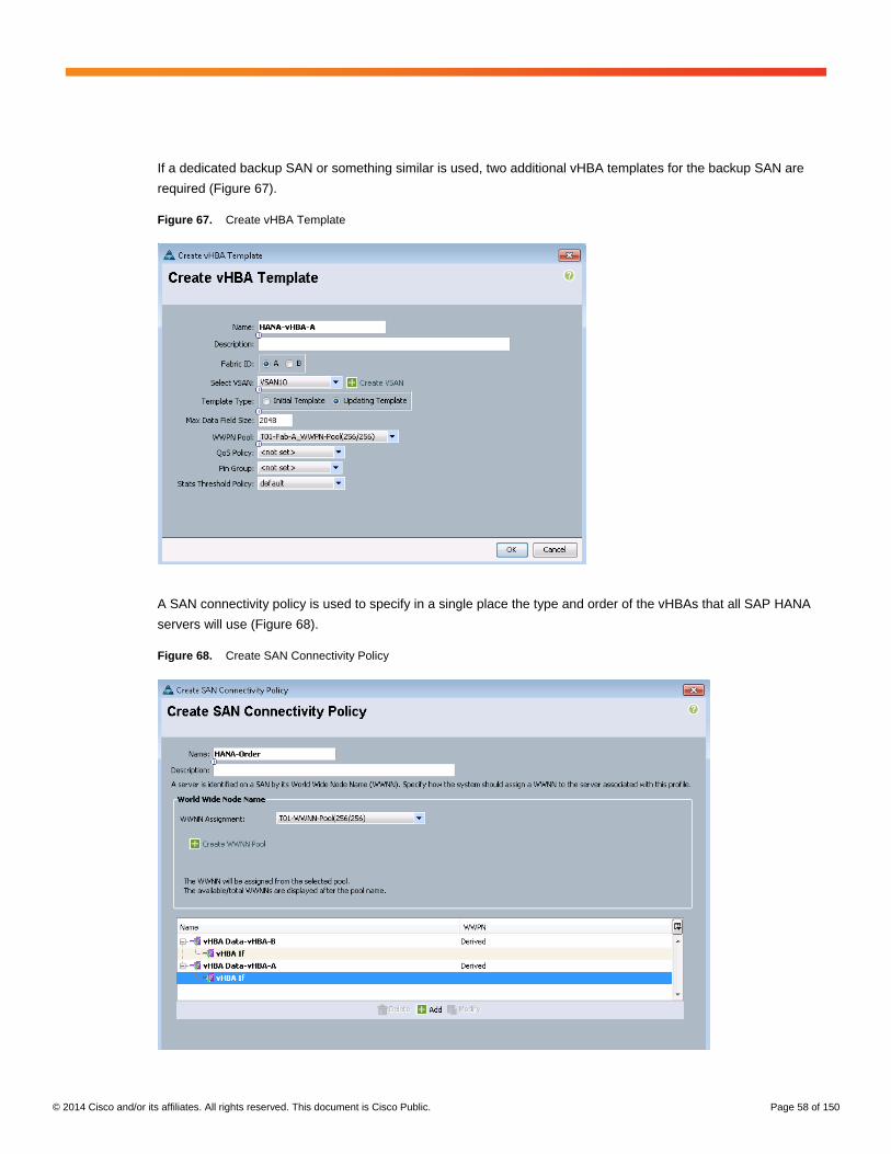
© 2014 Cisco and/or its affiliates. All rights reserved. This document is Cisco Public. Page 58 of 150
If a dedicated backup SAN or something similar is used, two additional vHBA templates for the backup SAN are
required (Figure 67).
Figure 67. Create vHBA Template
A SAN connectivity policy is used to specify in a single place the type and order of the vHBAs that all SAP HANA
servers will use (Figure 68).
Figure 68. Create SAN Connectivity Policy
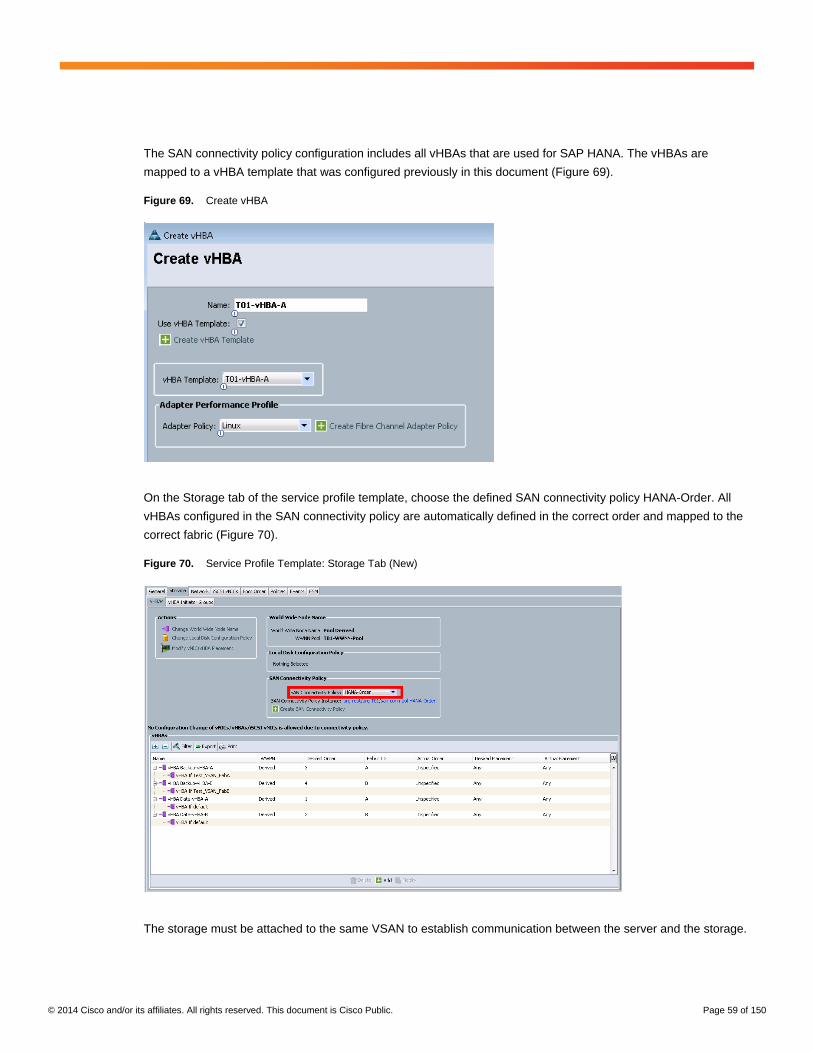
© 2014 Cisco and/or its affiliates. All rights reserved. This document is Cisco Public. Page 59 of 150
The SAN connectivity policy configuration includes all vHBAs that are used for SAP HANA. The vHBAs are
mapped to a vHBA template that was configured previously in this document (Figure 69).
Figure 69. Create vHBA
On the Storage tab of the service profile template, choose the defined SAN connectivity policy HANA-Order. All
vHBAs configured in the SAN connectivity policy are automatically defined in the correct order and mapped to the
correct fabric (Figure 70).
Figure 70. Service Profile Template: Storage Tab (New)
The storage must be attached to the same VSAN to establish communication between the server and the storage.

© 2014 Cisco and/or its affiliates. All rights reserved. This document is Cisco Public. Page 60 of 150
Direct-Attached Fibre Channel Storage
The direct-attached Fibre Channel storage configuration (Figure 71) is used for the Cisco Starter Kit Solution for
SAP HANA. Check the Cisco UCS Hardware Compatibility Matrix to determine whether the storage model
supports direct attachment to the fabric interconnects.
Figure 71. Direct Attached Fibre Channel Storage

© 2014 Cisco and/or its affiliates. All rights reserved. This document is Cisco Public. Page 61 of 150
The fabric interconnects must be configured using the Fibre Channel switch mode to work with direct-attached
Fibre Channel storage from different vendors. If Cisco UCS is running in Fibre Channel end-host mode, select Set
FC Switching Mode and set FC Mode to Switch (Figure 72). Both fabric interconnects will reboot to activate the
setting. The SAN zoning in this case must be performed in Cisco UCS.
Figure 72. Fabric Interconnect Details
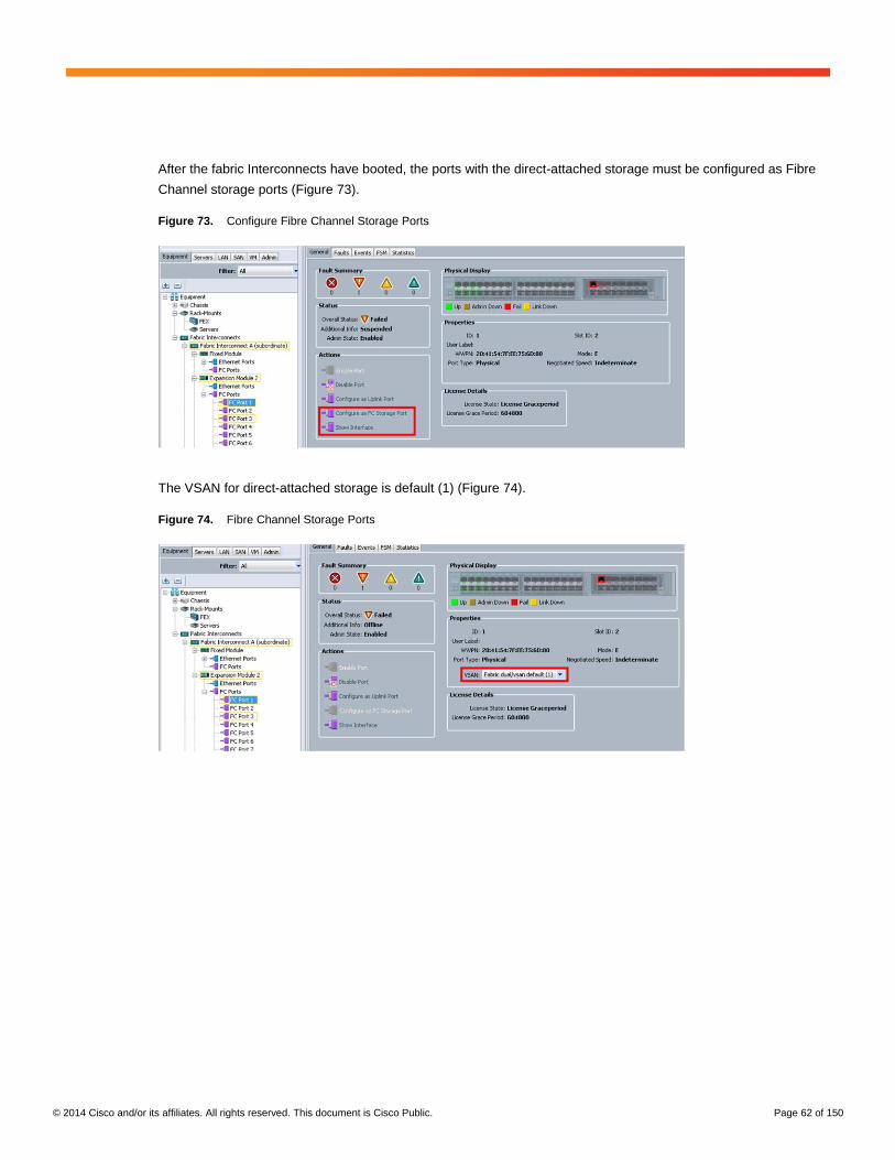
© 2014 Cisco and/or its affiliates. All rights reserved. This document is Cisco Public. Page 62 of 150
After the fabric Interconnects have booted, the ports with the direct-attached storage must be configured as Fibre
Channel storage ports (Figure 73).
Figure 73. Configure Fibre Channel Storage Ports
The VSAN for direct-attached storage is default (1) (Figure 74).
Figure 74. Fibre Channel Storage Ports

© 2014 Cisco and/or its affiliates. All rights reserved. This document is Cisco Public. Page 63 of 150
Storage Connection Policy (Zoning)
SAN zoning in Cisco UCS is defined by the storage connection policies on the SAN tab. For the Zoning Type
option, select Single Initiator Multiple Targets (Figure 75).
Figure 75. Storage Connection Policy: Start
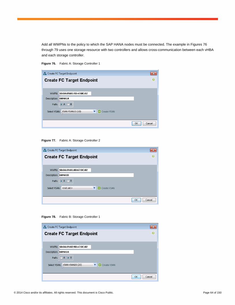
© 2014 Cisco and/or its affiliates. All rights reserved. This document is Cisco Public. Page 64 of 150
Add all WWPNs to the policy to which the SAP HANA nodes must be connected. The example in Figures 76
through 79 uses one storage resource with two controllers and allows cross-communication between each vHBA
and each storage controller.
Figure 76. Fabric A: Storage Controller 1
Figure 77. Fabric A: Storage Controller 2
Figure 78. Fabric B: Storage Controller 1

© 2014 Cisco and/or its affiliates. All rights reserved. This document is Cisco Public. Page 65 of 150
Figure 79. Fabric B: Storage Controller 2
The Policy should now look like Figure 80.
Figure 80. Storage Connection Policy
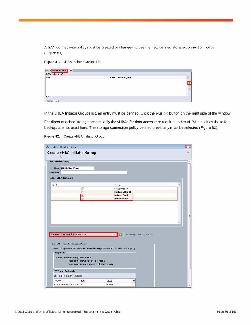
© 2014 Cisco and/or its affiliates. All rights reserved. This document is Cisco Public. Page 66 of 150
A SAN connectivity policy must be created or changed to use the new defined storage connection policy
(Figure 81).
Figure 81. vHBA Initiator Groups List
In the vHBA Initiator Groups list, an entry must be defined. Click the plus (+) button on the right side of the window.
For direct-attached storage access, only the vHBAs for data access are required; other vHBAs, such as those for
backup, are not used here. The storage connection policy defined previously must be selected (Figure 82).
Figure 82. Create vHBA Initiator Group
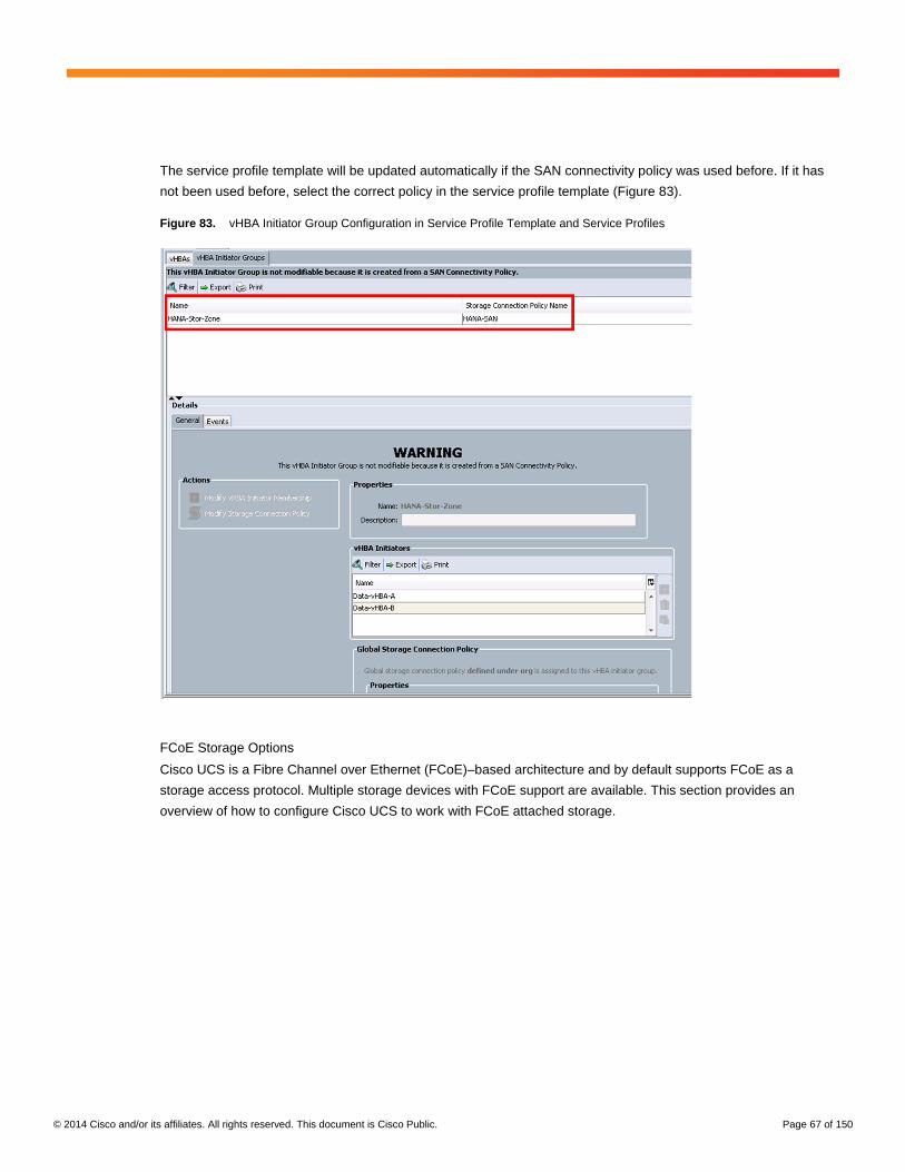
© 2014 Cisco and/or its affiliates. All rights reserved. This document is Cisco Public. Page 67 of 150
The service profile template will be updated automatically if the SAN connectivity policy was used before. If it has
not been used before, select the correct policy in the service profile template (Figure 83).
Figure 83. vHBA Initiator Group Configuration in Service Profile Template and Service Profiles
FCoE Storage Options
Cisco UCS is a Fibre Channel over Ethernet (FCoE)–based architecture and by default supports FCoE as a
storage access protocol. Multiple storage devices with FCoE support are available. This section provides an
overview of how to configure Cisco UCS to work with FCoE attached storage.
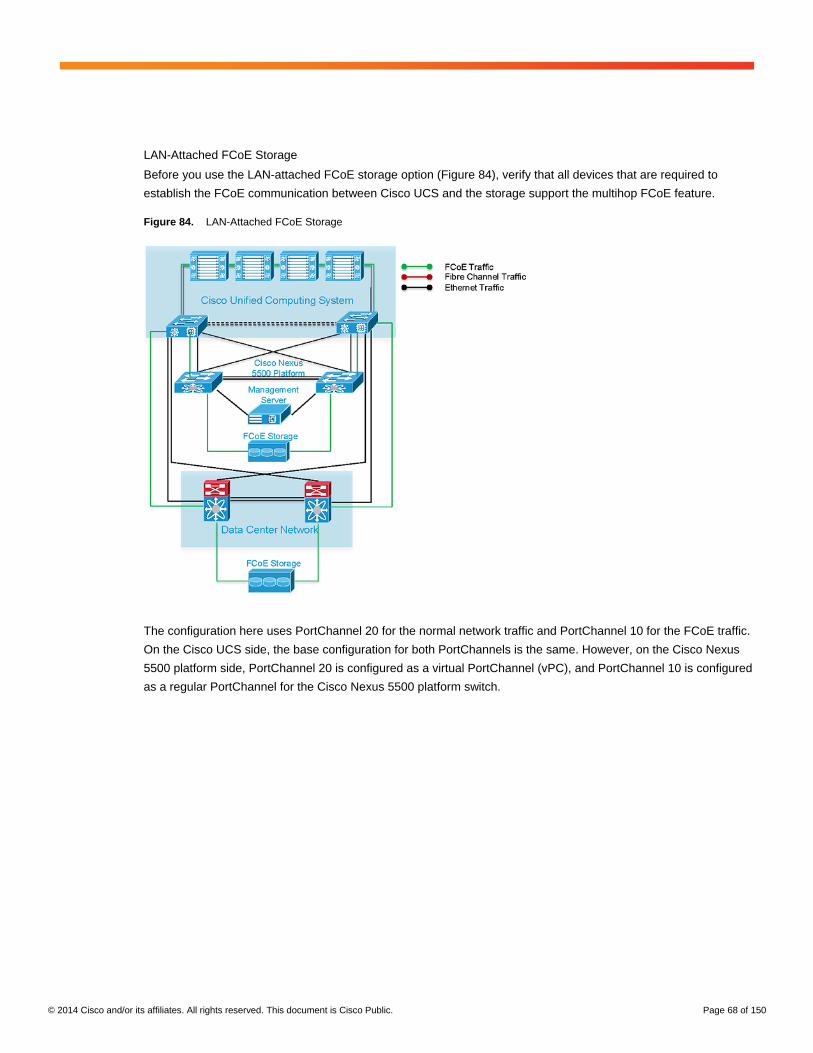
© 2014 Cisco and/or its affiliates. All rights reserved. This document is Cisco Public. Page 68 of 150
LAN-Attached FCoE Storage
Before you use the LAN-attached FCoE storage option (Figure 84), verify that all devices that are required to
establish the FCoE communication between Cisco UCS and the storage support the multihop FCoE feature.
Figure 84. LAN-Attached FCoE Storage
The configuration here uses PortChannel 20 for the normal network traffic and PortChannel 10 for the FCoE traffic.
On the Cisco UCS side, the base configuration for both PortChannels is the same. However, on the Cisco Nexus
5500 platform side, PortChannel 20 is configured as a virtual PortChannel (vPC), and PortChannel 10 is configured
as a regular PortChannel for the Cisco Nexus 5500 platform switch.

© 2014 Cisco and/or its affiliates. All rights reserved. This document is Cisco Public. Page 69 of 150
Cisco UCS uses FCoE by default, and each VSAN is automatically mapped to an FCoE VLAN ID. This FCoE
VLAN ID must match the VLAN ID on the data center network switches. Verify, and if required change, the VLAN
ID for each VSAN that will be used (Figure 85).
Figure 85. VSAN Details: Verify the FCoE VLAN ID
FCoE PortChannel Configuration
Dedicated uplink ports or PortChannels can be used for FCoE traffic to the next switch. Cisco UCS also supports
unified traffic on the uplink ports. Verify that dedicated or unified traffic can be used because not all switches
support unified traffic.
Note: If unified traffic over a PortChannel is used together with Cisco Nexus 5500 platform switches, vPC
configuration is not allowed. Check the Cisco Nexus 5500 platform documentation for more information.
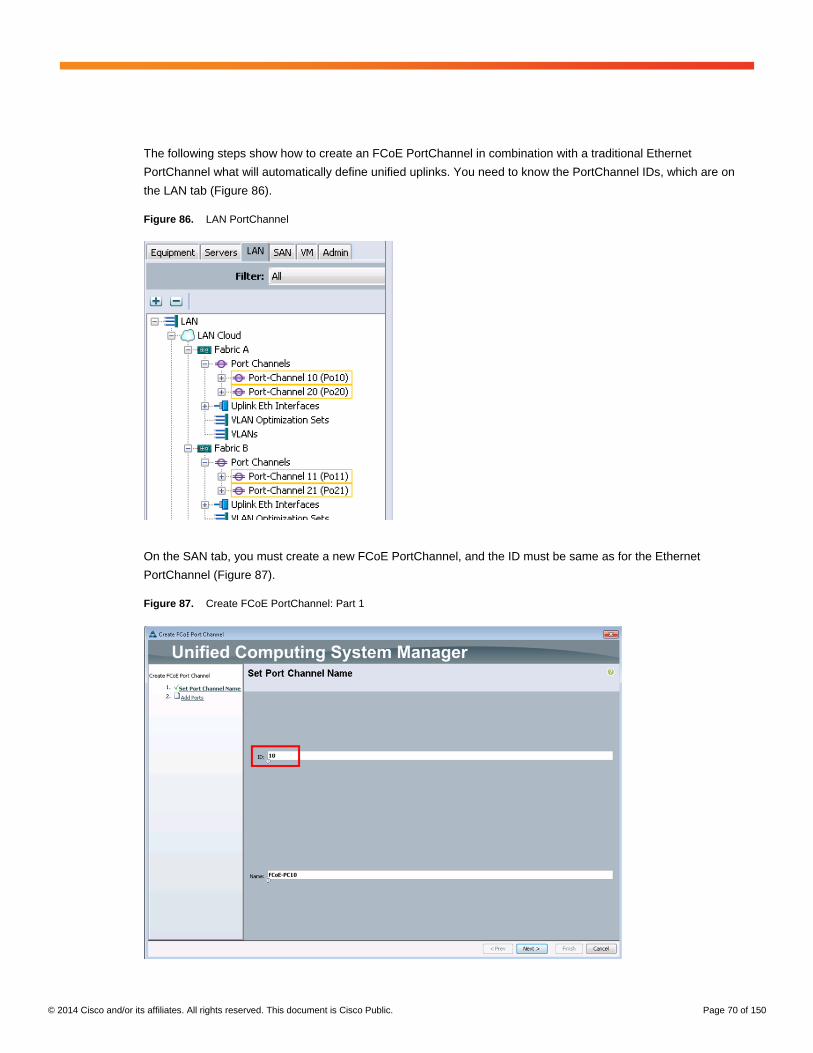
© 2014 Cisco and/or its affiliates. All rights reserved. This document is Cisco Public. Page 70 of 150
The following steps show how to create an FCoE PortChannel in combination with a traditional Ethernet
PortChannel what will automatically define unified uplinks. You need to know the PortChannel IDs, which are on
the LAN tab (Figure 86).
Figure 86. LAN PortChannel
On the SAN tab, you must create a new FCoE PortChannel, and the ID must be same as for the Ethernet
PortChannel (Figure 87).
Figure 87. Create FCoE PortChannel: Part 1
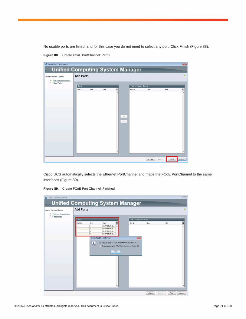
© 2014 Cisco and/or its affiliates. All rights reserved. This document is Cisco Public. Page 71 of 150
No usable ports are listed, and for this case you do not need to select any port. Click Finish (Figure 88).
Figure 88. Create FCoE PortChannel: Part 2
Cisco UCS automatically selects the Ethernet PortChannel and maps the FCoE PortChannel to the same
interfaces (Figure 89).
Figure 89. Create FCoE Port Channel: Finished

© 2014 Cisco and/or its affiliates. All rights reserved. This document is Cisco Public. Page 72 of 150
The role of the Ethernet uplink port changed from Network to Unified Uplink. Now the default Ethernet traffic and
the FCoE traffic will use the same connections (Figure 90).
Figure 90. Ethernet Port: General Tab
To build the connection between the vHBA and the FCoE PortChannel, a SAN pin group is required (Figure 91).
Figure 91. SAN Pin Group
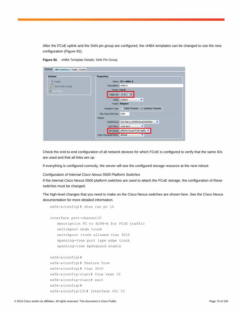
© 2014 Cisco and/or its affiliates. All rights reserved. This document is Cisco Public. Page 73 of 150
After the FCoE uplink and the SAN pin group are configured, the vHBA templates can be changed to use the new
configuration (Figure 92).
Figure 92. vHBA Template Details: SAN Pin Group
Check the end-to-end configuration of all network devices for which FCoE is configured to verify that the same IDs
are used and that all links are up.
If everything is configured correctly, the server will see the configured storage resource at the next reboot.
Configuration of Internal Cisco Nexus 5500 Platform Switches
If the internal Cisco Nexus 5500 platform switches are used to attach the FCoE storage, the configuration of these
switches must be changed.
The high-level changes that you need to make on the Cisco Nexus switches are shown here. See the Cisco Nexus
documentation for more detailed information.
nx5k-a(config)# show run po 10
interface port-channel10
description PC to 6248-A for FCoE traffic
switchport mode trunk
switchport trunk allowed vlan 3010
spanning-tree port type edge trunk
spanning-tree bpduguard enable
nx5k-a(config)#
nx5k-a(config)# feature fcoe
nx5k-a(config)# vlan 3010
nx5k-a(config-vlan)# fcoe vsan 10
nx5k-a(config-vlan)# exit
nx5k-a(config)#
nx5k-a(config-if)# interface vfc 10
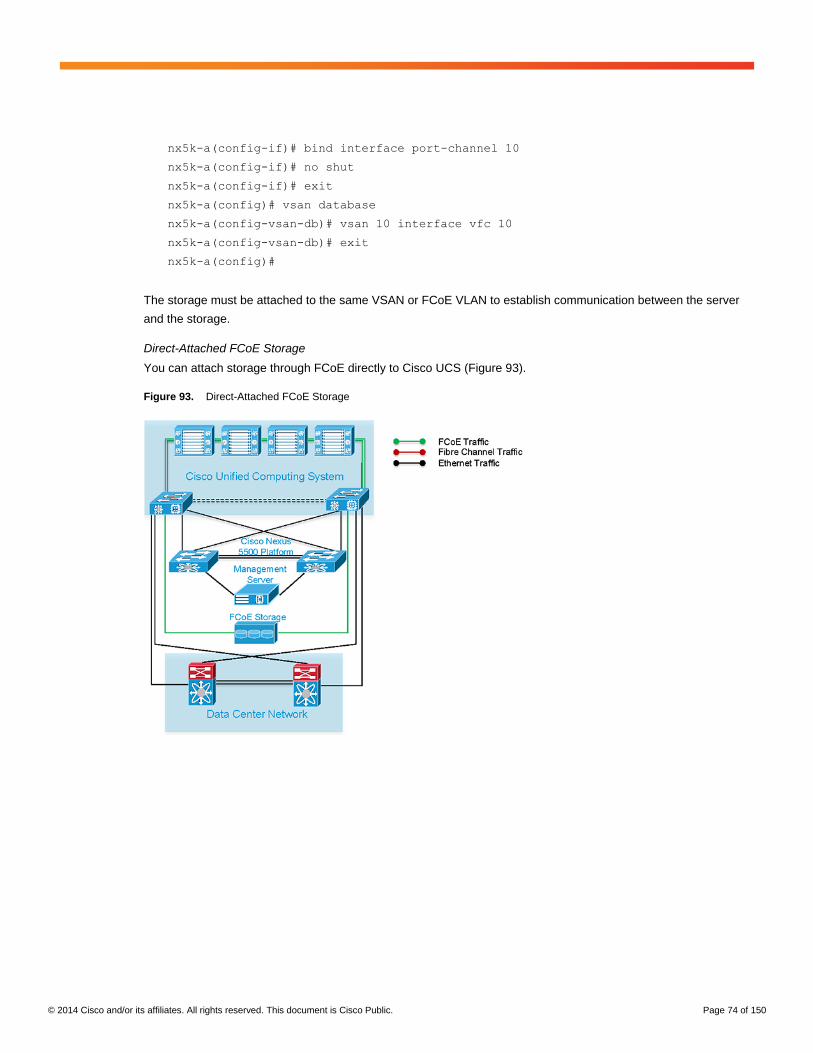
© 2014 Cisco and/or its affiliates. All rights reserved. This document is Cisco Public. Page 74 of 150
nx5k-a(config-if)# bind interface port-channel 10
nx5k-a(config-if)# no shut
nx5k-a(config-if)# exit
nx5k-a(config)# vsan database
nx5k-a(config-vsan-db)# vsan 10 interface vfc 10
nx5k-a(config-vsan-db)# exit
nx5k-a(config)#
The storage must be attached to the same VSAN or FCoE VLAN to establish communication between the server
and the storage.
Direct-Attached FCoE Storage
You can attach storage through FCoE directly to Cisco UCS (Figure 93).
Figure 93. Direct-Attached FCoE Storage

© 2014 Cisco and/or its affiliates. All rights reserved. This document is Cisco Public. Page 75 of 150
For direct-attached FCoE storage, a FCoE PortChannel cannot be used. Instead, the interfaces on the fabric
interconnects must be reconfigured as FCoE storage ports (Figure 94).
Figure 94. Ethernet Port Details: Configure as FCoE Storage Port
The port role changes from Uplink to Fcoe Storage, and the VSAN selection is available (Figure 95).
Figure 95. Ethernet Port Details: FCoE Storage

© 2014 Cisco and/or its affiliates. All rights reserved. This document is Cisco Public. Page 76 of 150
The vHBA templates configuration must be changed to the same VSAN as configured on the FCoE storage port to
allow communication with the direct-attached FCoE storage (Figure 96).
Figure 96. vHBA Details
If the vHBA template is an updating template, the service profile template and the service profiles
automatically update.
NFS Storage Options
As with Fibre Channel storage options, multiple NFS storage options are available.

© 2014 Cisco and/or its affiliates. All rights reserved. This document is Cisco Public. Page 77 of 150
Direct-Attached NFS Storage
With the Cisco UCS appliance port configuration, you can connect NFS storage directly to the Cisco UCS fabric
interconnects (Figure 97). Special conditions apply to this configuration in the event of a failure. The most common
ones are described in the appendix titled “Direct-Attached NFS Failure Scenarios” in this document.
Figure 97. Direct-Attached NFS Storage
Figure 98 shows an unconfigured Appliances section on the LAN tab. No interfaces or VLAN is configured.
Figure 98. Appliance Section on the LAN tab
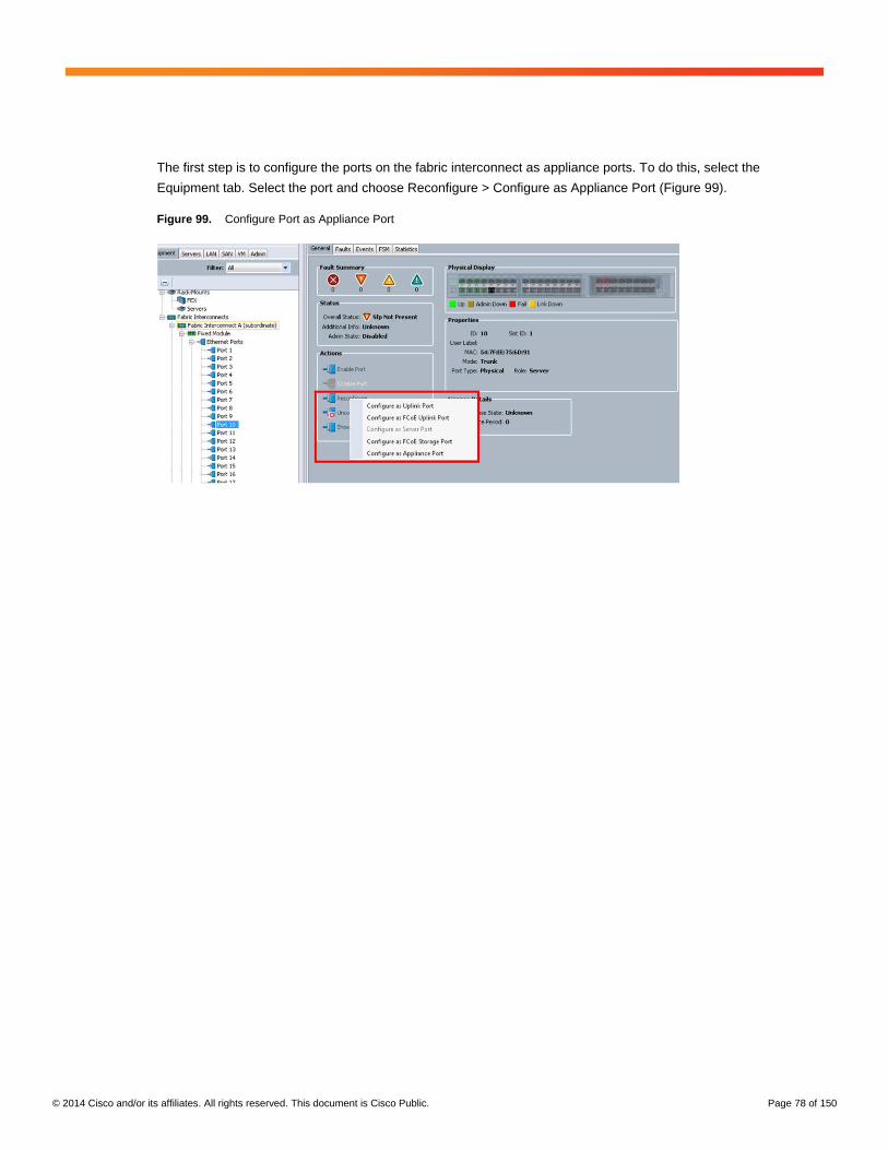
© 2014 Cisco and/or its affiliates. All rights reserved. This document is Cisco Public. Page 78 of 150
The first step is to configure the ports on the fabric interconnect as appliance ports. To do this, select the
Equipment tab. Select the port and choose Reconfigure > Configure as Appliance Port (Figure 99).
Figure 99. Configure Port as Appliance Port

© 2014 Cisco and/or its affiliates. All rights reserved. This document is Cisco Public. Page 79 of 150
In the new window, select Trunk as the port mode and click Create VLAN (Figure 100).
Figure 100. Appliance Port Configuration Details: No VLAN Configured
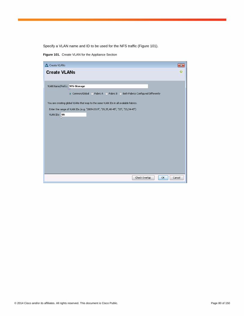
© 2014 Cisco and/or its affiliates. All rights reserved. This document is Cisco Public. Page 80 of 150
Specify a VLAN name and ID to be used for the NFS traffic (Figure 101).
Figure 101. Create VLAN for the Appliance Section
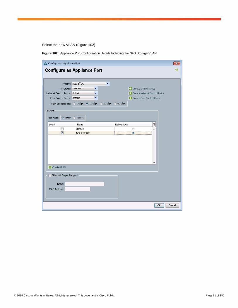
© 2014 Cisco and/or its affiliates. All rights reserved. This document is Cisco Public. Page 81 of 150
Select the new VLAN (Figure 102).
Figure 102. Appliance Port Configuration Details Including the NFS Storage VLAN

© 2014 Cisco and/or its affiliates. All rights reserved. This document is Cisco Public. Page 82 of 150
After the configuration, the port role changes to Appliance Storage (Figure 103).
Figure 103. Port Details
Configure all ports to which a storage resource is attached on fabric interconnects A and B. You need to create the
VLAN only once, and it is then available for selection for all other instances. The Appliances section shows all
configured ports and VLANs (Figure 104).
Figure 104. Appliance Section After Ports Are Configured
The following steps are optional, depending on your setup.

© 2014 Cisco and/or its affiliates. All rights reserved. This document is Cisco Public. Page 83 of 150
If the OS boot methodology used is PXE-boot with the root file system on NFS, an additional VLAN for the boot
network is required on the appliance ports.
In the Appliances section of the LAN tab, create a new VLAN under VLANs (Figure 105).
Figure 105. Create VLAN for PXE Boot and NFS Root in Appliances Section
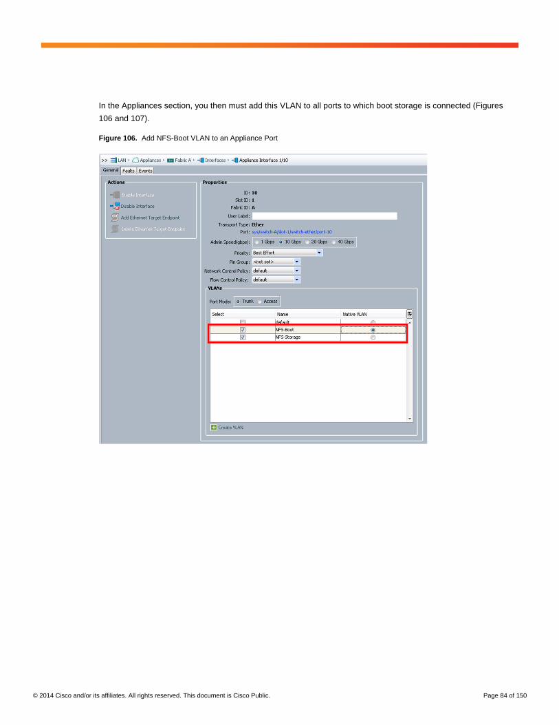
© 2014 Cisco and/or its affiliates. All rights reserved. This document is Cisco Public. Page 84 of 150
In the Appliances section, you then must add this VLAN to all ports to which boot storage is connected (Figures
106 and 107).
Figure 106. Add NFS-Boot VLAN to an Appliance Port

© 2014 Cisco and/or its affiliates. All rights reserved. This document is Cisco Public. Page 85 of 150
Figure 107. Appliances Section After VLAN Configuration
LAN-Attached NFS Storage
One of the most common configurations uses NFS storage with LAN switches (Figure 108). These can be the data
center network switches or the internal Cisco Nexus 5500 platform switches.
Figure 108. LAN-Attached NFS Storage
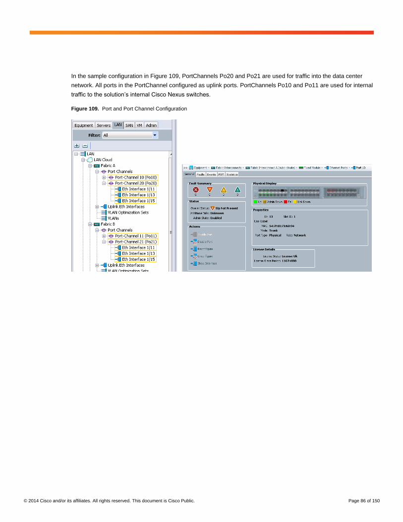
© 2014 Cisco and/or its affiliates. All rights reserved. This document is Cisco Public. Page 86 of 150
In the sample configuration in Figure 109, PortChannels Po20 and Po21 are used for traffic into the data center
network. All ports in the PortChannel configured as uplink ports. PortChannels Po10 and Po11 are used for internal
traffic to the solution’s internal Cisco Nexus switches.
Figure 109. Port and Port Channel Configuration
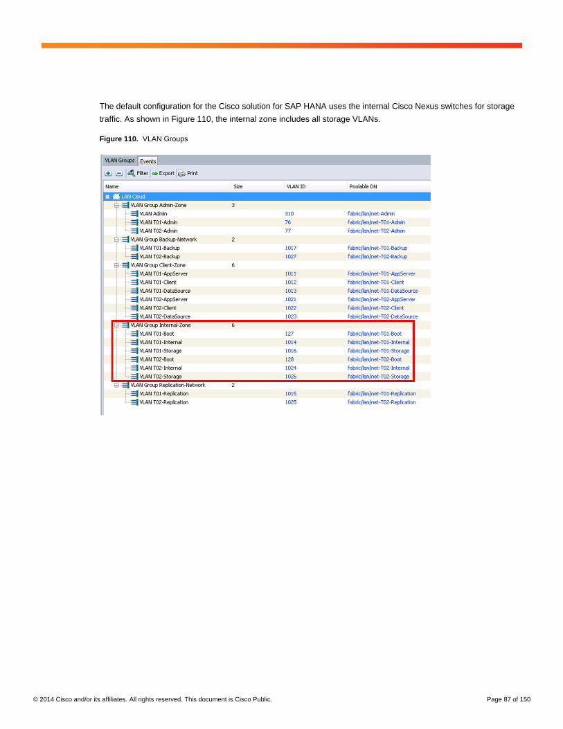
© 2014 Cisco and/or its affiliates. All rights reserved. This document is Cisco Public. Page 87 of 150
The default configuration for the Cisco solution for SAP HANA uses the internal Cisco Nexus switches for storage
traffic. As shown in Figure 110, the internal zone includes all storage VLANs.
Figure 110. VLAN Groups

© 2014 Cisco and/or its affiliates. All rights reserved. This document is Cisco Public. Page 88 of 150
Create a VLAN group for storage traffic to route this traffic to the data center network. Specify a name and select
all VLANs used for storage traffic (Figure 111).
Figure 111. Create VLAN Group

© 2014 Cisco and/or its affiliates. All rights reserved. This document is Cisco Public. Page 89 of 150
On the next screen (Figure 112), dedicated uplink ports for the storage traffic are selectable. If PortChannels are
used, click Next.
Figure 112. Create VLAN Group: Port Selection
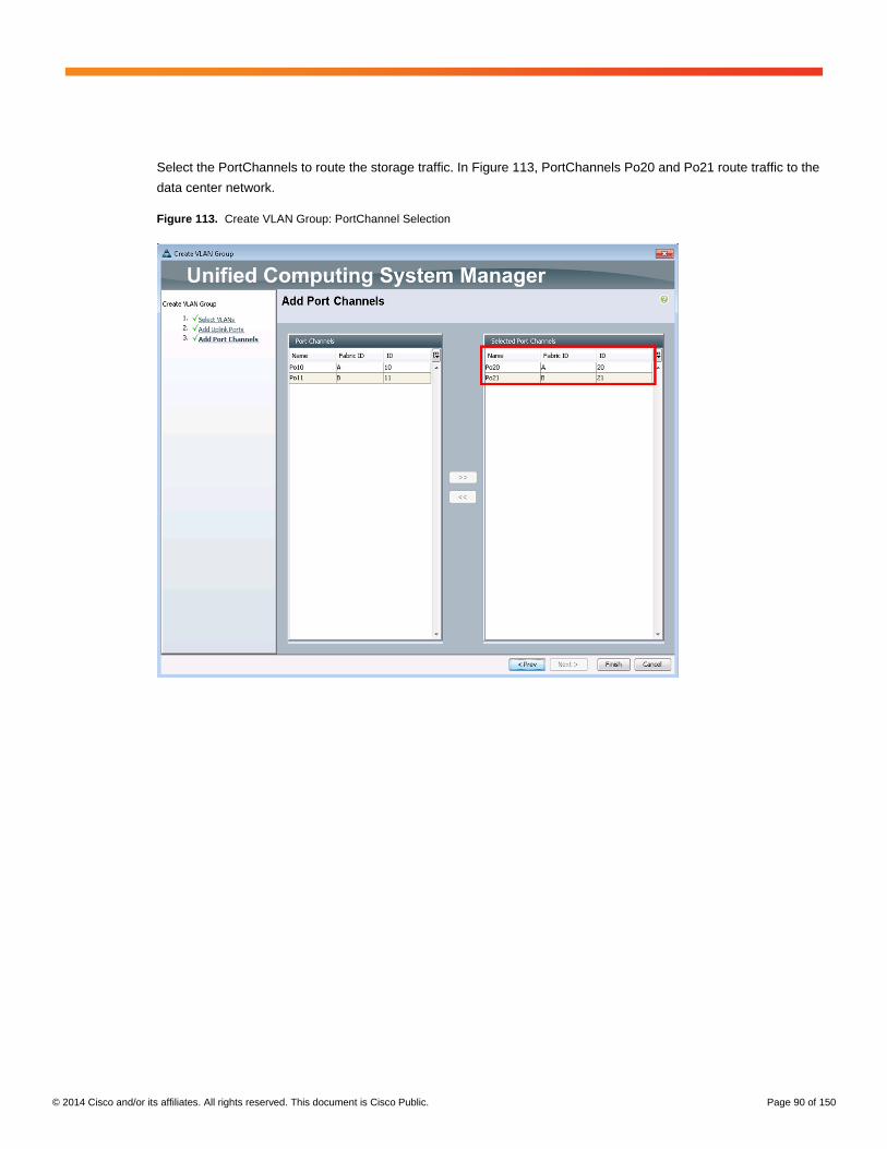
© 2014 Cisco and/or its affiliates. All rights reserved. This document is Cisco Public. Page 90 of 150
Select the PortChannels to route the storage traffic. In Figure 113, PortChannels Po20 and Po21 route traffic to the
data center network.
Figure 113. Create VLAN Group: PortChannel Selection
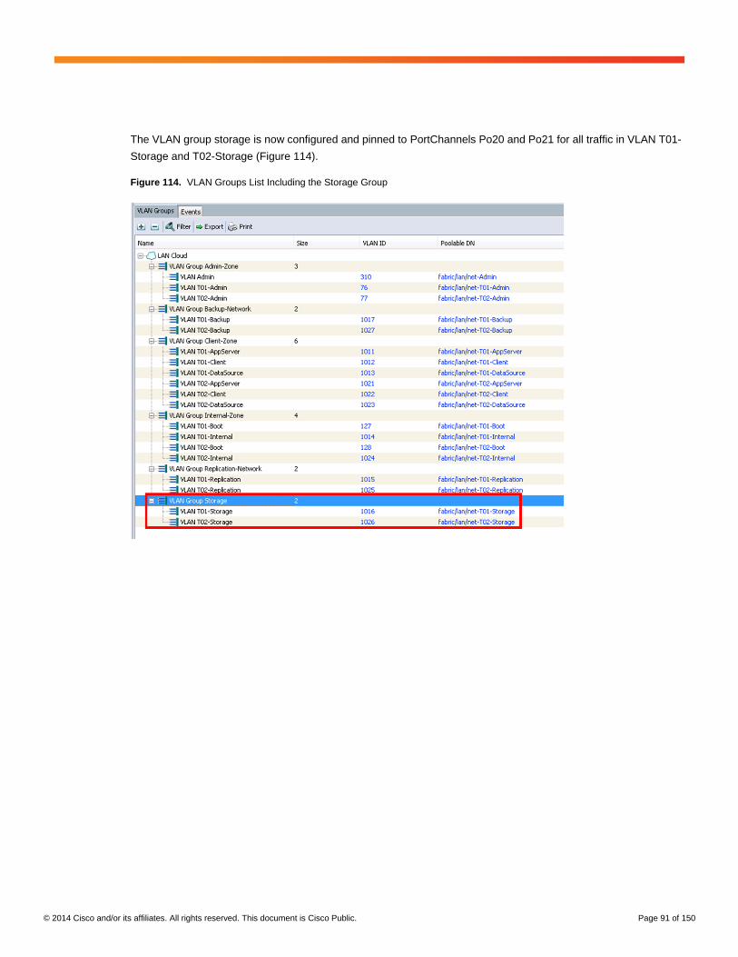
© 2014 Cisco and/or its affiliates. All rights reserved. This document is Cisco Public. Page 91 of 150
The VLAN group storage is now configured and pinned to PortChannels Po20 and Po21 for all traffic in VLAN T01-
Storage and T02-Storage (Figure 114).
Figure 114. VLAN Groups List Including the Storage Group

© 2014 Cisco and/or its affiliates. All rights reserved. This document is Cisco Public. Page 92 of 150
The storage traffic now goes out to the data center network. The VLAN IDs used in Cisco UCS must match the
VLAN IDs in the data center network. To change a VLAN ID, open the required VLAN on the LAN tab and change
the VLAN ID as required (Figure 115).
Figure 115. VLAN T01-Storage Details
You also should check the MTU size on all devices. The recommended setting is 9000.
Check the MTU size for the storage vNIC template as shown in Figure 116.
Figure 116. T01-Storage vNIC Template Details

© 2014 Cisco and/or its affiliates. All rights reserved. This document is Cisco Public. Page 93 of 150
Internal Cisco Nexus 5500 Platform Switch
There are two methodologies for connecting the storage to the internal Cisco Nexus switches:
● Directly connected: storage to Cisco Nexus switch
● Indirectly connected: storage to data center network to Cisco Nexus switch
Figure 117 shows the directly connected storage methodology.
Figure 117. NFS Storage Directly Attached to Solution Switches
This option is similar to the Cisco solution for SAP HANA with NFS storage. Because the internal solution switches
are a critical part of this configuration and affect overall SAP HANA performance, configuration changes are difficult
to make.

© 2014 Cisco and/or its affiliates. All rights reserved. This document is Cisco Public. Page 94 of 150
As an example, we show the network port configuration of the Cisco Nexus switches and the NetApp FAS storage
Cisco use in the appliance-like solutions (Figure 118).
Figure 118. Cisco Nexus Port Diagram
The first NetApp FAS DEVICE is connected to the ports Eth1/13 and Eth1/15 on both switches.
Cisco Nexus-A configuration:
interface Ethernet1/13
description NetApp1_CtrlA-e1a
untagged cos 5
switchport mode trunk
switchport trunk allowed vlan 201-204
spanning-tree port type edge trunk
spanning-tree bpduguard enable
channel-group 40 mode active
no shutdown
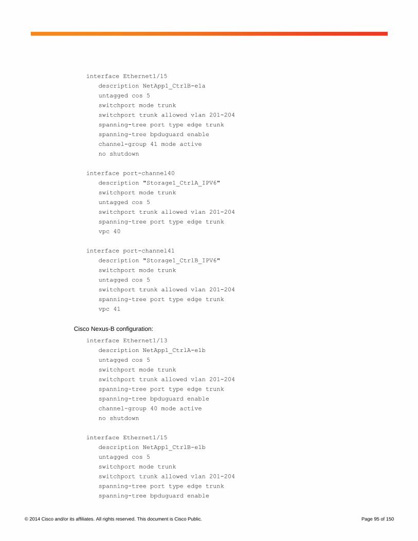
© 2014 Cisco and/or its affiliates. All rights reserved. This document is Cisco Public. Page 95 of 150
interface Ethernet1/15
description NetApp1_CtrlB-e1a
untagged cos 5
switchport mode trunk
switchport trunk allowed vlan 201-204
spanning-tree port type edge trunk
spanning-tree bpduguard enable
channel-group 41 mode active
no shutdown
interface port-channel40
description "Storage1_CtrlA_IPV6"
switchport mode trunk
untagged cos 5
switchport trunk allowed vlan 201-204
spanning-tree port type edge trunk
vpc 40
interface port-channel41
description "Storage1_CtrlB_IPV6"
switchport mode trunk
untagged cos 5
switchport trunk allowed vlan 201-204
spanning-tree port type edge trunk
vpc 41
Cisco Nexus-B configuration:
interface Ethernet1/13
description NetApp1_CtrlA-e1b
untagged cos 5
switchport mode trunk
switchport trunk allowed vlan 201-204
spanning-tree port type edge trunk
spanning-tree bpduguard enable
channel-group 40 mode active
no shutdown
interface Ethernet1/15
description NetApp1_CtrlB-e1b
untagged cos 5
switchport mode trunk
switchport trunk allowed vlan 201-204
spanning-tree port type edge trunk
spanning-tree bpduguard enable
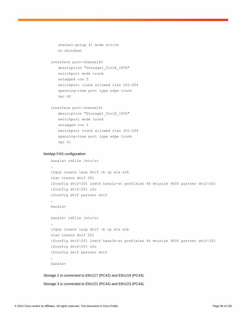
© 2014 Cisco and/or its affiliates. All rights reserved. This document is Cisco Public. Page 96 of 150
channel-group 41 mode active
no shutdown
interface port-channel40
description "Storage1_CtrlA_IPV6"
switchport mode trunk
untagged cos 5
switchport trunk allowed vlan 201-204
spanning-tree port type edge trunk
vpc 40
interface port-channel41
description "Storage1_CtrlB_IPV6"
switchport mode trunk
untagged cos 5
switchport trunk allowed vlan 201-204
spanning-tree port type edge trunk
vpc 41
NetApp FAS configuration:
hana1a> rdfile /etc/rc
…
ifgrp create lacp dvif -b ip e1a e1b
vlan create dvif 201
ifconfig dvif-201 inet6 hana1a-st prefixlen 64 mtusize 9000 partner dvif-201
ifconfig dvif-201 nfo
ifconfig dvif partner dvif
…
hana1a>
hana1b> rdfile /etc/rc
…
ifgrp create lacp dvif -b ip e1a e1b
vlan create dvif 201
ifconfig dvif-201 inet6 hana1b-st prefixlen 64 mtusize 9000 partner dvif-201
ifconfig dvif-201 nfo
ifconfig dvif partner dvif
…
hana1b>
Storage 2 is connected to Eth1/17 (PC42) and Eth1/19 (PC43).
Storage 3 is connected to Eth1/21 (PC44) and Eth1/23 (PC44).

© 2014 Cisco and/or its affiliates. All rights reserved. This document is Cisco Public. Page 97 of 150
The configuration on the Cisco Nexus switches and on the NetApp FAS device follows the same schema as shown
for the first storage.
Regardless of which storage device is used, Link Aggregation Control Protocol (LACP) must be supported by the
storage, and the VLAN ID must be configured properly end to end from the storage over the network to the server.
Figure 119 shows the indirectly connected storage methodology.
Figure 119. NFS Storage Indirectly Attached to Solution Switches
This option is technically valid but difficult to implement, so the LAN-Attached NFS Storage options shown earlier in
this document is recommended.
Boot Options
Because the Cisco solution for the SAP HANA scale-out implementation is designed to work with PXE boot and the
NFS root file system and does not include local storage to install the operating system, you need to define the
boot option:
● Local disk boot: Two SAS disks to store the OS must be ordered for each Cisco UCS B440 M2 blade.
● PXE boot with NFS root: NFS storage with redundant paths and capacity for the OS must be provided.
● SAN boot: Fibre Channel storage directly attached or SAN attached must be provided.
● Small Computer System Interface over IP (iSCSI) boot: LAN-attached block storage with iSCSI capability
must be provided.
Each boot option has advantages and disadvantages, and the choice should be made based on internal best
practices: for example, if SAN boot is used for the other servers, this option may be the best one for this installation
as well.

© 2014 Cisco and/or its affiliates. All rights reserved. This document is Cisco Public. Page 98 of 150
For PXE boot, the solution’s internal management servers can be used for DHCP and TFTP service. All required
components are installed and preconfigured for the appliance-like solution model described in this document.
PXE Boot
For PXE boot with the Linux root file system on NFS, you need to configure the PXE server and the NFS storage
with access to the boot VLAN. See the SUSE or Red Hat documentation for more information.
Service Profile Template Configuration
The boot policy in the service profile template must be changed to boot from LAN (Figure 120).
Figure 120. Boot Policy Example for PXE Boot
SAN Boot
For SAN boot, vHBAs must be configured. and the WWPNs of the storage are required. As a best practice, the
SAN zoning should allow each HBA to see two controllers, storage processors, and front-end ports of the boot
storage. The example shown in Figure 121 uses NetApp FAS storage, and each HBA can see both NetApp
FAS controllers.

© 2014 Cisco and/or its affiliates. All rights reserved. This document is Cisco Public. Page 99 of 150
Service Profile Template Configuration
The boot policy must be changed to enable SAN boot. If the boot logical unit number (LUN) should be reachable
over multiple paths, the SAN boot configuration should list the WWPNs of the storage mapped to the two vHBAs
on the server (Figures 121 and 122).
Figure 121. Boot Policy Example for SAN Boot: NetApp FAS
Figure 122. Boot Policy Example for SAN Boot: EMC VNX
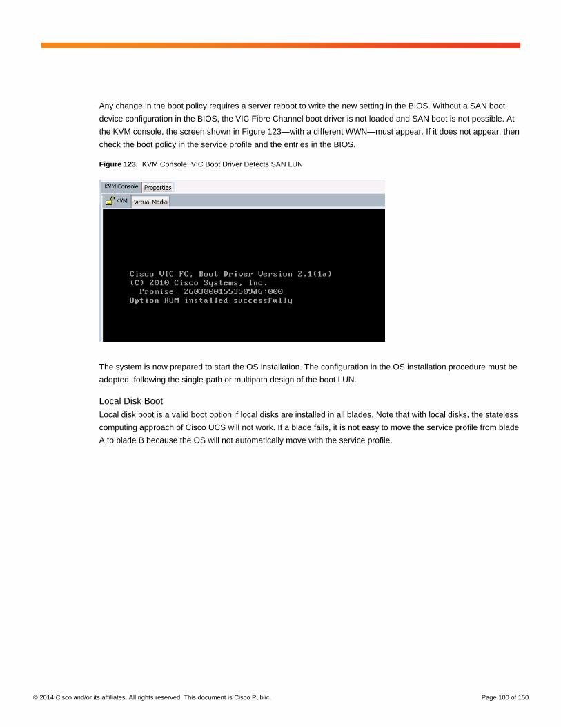
© 2014 Cisco and/or its affiliates. All rights reserved. This document is Cisco Public. Page 100 of 150
Any change in the boot policy requires a server reboot to write the new setting in the BIOS. Without a SAN boot
device configuration in the BIOS, the VIC Fibre Channel boot driver is not loaded and SAN boot is not possible. At
the KVM console, the screen shown in Figure 123—with a different WWN—must appear. If it does not appear, then
check the boot policy in the service profile and the entries in the BIOS.
Figure 123. KVM Console: VIC Boot Driver Detects SAN LUN
The system is now prepared to start the OS installation. The configuration in the OS installation procedure must be
adopted, following the single-path or multipath design of the boot LUN.
Local Disk Boot
Local disk boot is a valid boot option if local disks are installed in all blades. Note that with local disks, the stateless
computing approach of Cisco UCS will not work. If a blade fails, it is not easy to move the service profile from blade
A to blade B because the OS will not automatically move with the service profile.

© 2014 Cisco and/or its affiliates. All rights reserved. This document is Cisco Public. Page 101 of 150
Local Disk Configuration Policy
The Cisco UCS B440 M2 blades come with an onboard RAID controller to manage the four disks slots. The easiest
way to configure the RAID controller is to use a local disk configuration policy to specify the RAID type. A best
practice is to use two disks in a RAID 1 configuration to recover from a disk failure (Figure 124).
Figure 124. Local Disk Configuration Policy
Service Profile Template Configuration
The defined local disk configuration policy can be used in the service profile template. On the Storage tab, select
Change Local Disk Configuration Policy (Figure 125).
Figure 125. Service Profile Template: Storage Tab

© 2014 Cisco and/or its affiliates. All rights reserved. This document is Cisco Public. Page 102 of 150
Select the defined policy for RAID 1. In Figure 126, it is named Mirror.
Figure 126. Service Profile Template: Change Local Disk Configuration Policy
All service profiles mapped to this service profile template now use the new policy (Figure 127). This change
requires a server reboot to become active.
Figure 127. Service Profile Template with Local Disk Policy
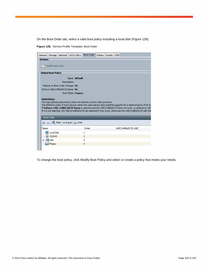
© 2014 Cisco and/or its affiliates. All rights reserved. This document is Cisco Public. Page 103 of 150
On the Boot Order tab, select a valid boot policy including a local disk (Figure 128).
Figure 128. Service Profile Template: Boot Order
To change the boot policy, click Modify Boot Policy and select or create a policy that meets your needs.

© 2014 Cisco and/or its affiliates. All rights reserved. This document is Cisco Public. Page 104 of 150
The Cisco UCS Manager default policy is preconfigured for local disk boot. There is no need to specify a new
policy here (Figure 129).
Figure 129. Service Profile Template: Modify Boot Policy

© 2014 Cisco and/or its affiliates. All rights reserved. This document is Cisco Public. Page 105 of 150
Cisco UCS Manager automatically reconfigures the RAID controller and creates a virtual drive as RAID1 on the
available disks, as shown in Figure 130.
Figure 130. KVM Screen: LSI RAID Configuration Summary
Many other options can be used to configure the local disks based on the RAID controller, or they can be
configured as single disks mapped to the OS with a software mirror created. The configuration shown here is one
recommended for the local disk boot option, but it is not the only configuration that is supported.
Operating System Installation
This document describes only the parts of the OS installation process relevant to SAP HANA; it does not provide a
detailed step-by-step guide for the whole installation process.
Every person installing an OS used for SAP HANA should read all related information at http://www.saphana.com/,
the SAP HANA installation guides, and the SAP notes. This document does not necessarily reflect any changes in
the SAP requirements.
SUSE Linux Enterprise Server
This section discusses the OS installation using the local disk boot option. The storage configuration and file
system layout do not need to be changed because the example here uses the default SLES selection on the
local RAID 1 controller. For the SAN and PXE boot options, the storage and file system configurations would
be different.
Note: Use the SAP HANA installation guides and follow your organization’s best practices to choose the best file
system layout for the installation.
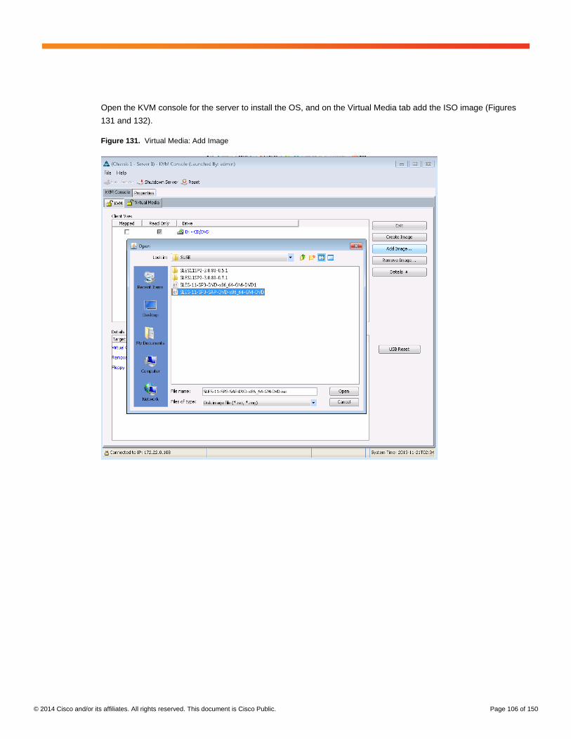
© 2014 Cisco and/or its affiliates. All rights reserved. This document is Cisco Public. Page 106 of 150
Open the KVM console for the server to install the OS, and on the Virtual Media tab add the ISO image (Figures
131 and 132).
Figure 131. Virtual Media: Add Image
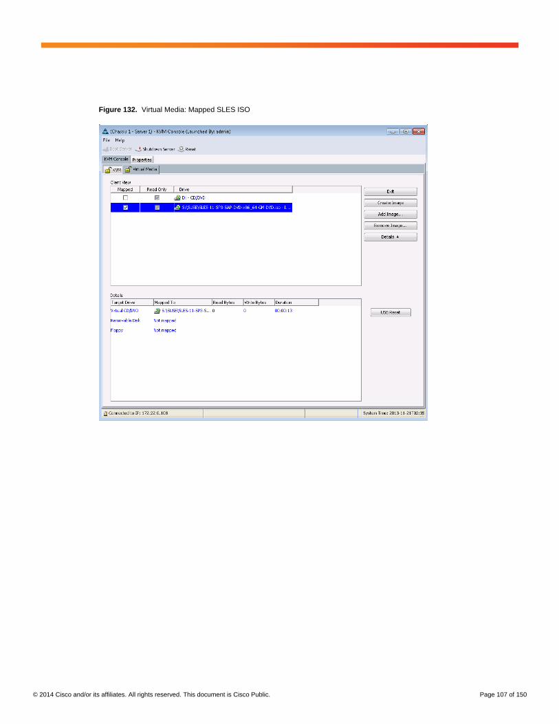
© 2014 Cisco and/or its affiliates. All rights reserved. This document is Cisco Public. Page 107 of 150
Figure 132. Virtual Media: Mapped SLES ISO

© 2014 Cisco and/or its affiliates. All rights reserved. This document is Cisco Public. Page 108 of 150
After the server is powered on and an ISO image is mapped to the virtual CD, the installation media is used to boot
the system. In the example in Figure 133, the default Installation procedure is used.
Figure 133. Boot Selection Screen
Follow the instructions on the screen and use your internal recommended options and best practices to proceed
with the installation. The figures that follow show only the parts of the screen with specific settings recommended
by SAP or Cisco. Some settings are required by SAP and documented in the SAP HANA installation guides, and
some are only recommendations based on the solution tests.
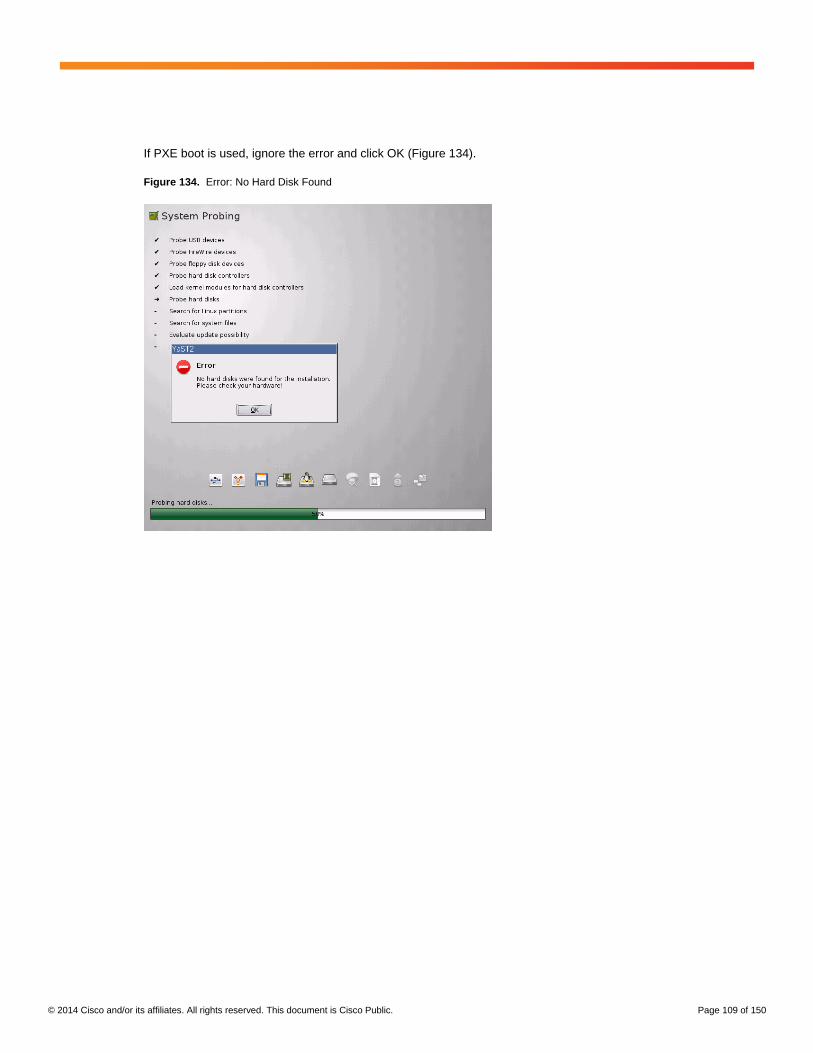
© 2014 Cisco and/or its affiliates. All rights reserved. This document is Cisco Public. Page 109 of 150
If PXE boot is used, ignore the error and click OK (Figure 134).
Figure 134. Error: No Hard Disk Found

© 2014 Cisco and/or its affiliates. All rights reserved. This document is Cisco Public. Page 110 of 150
SAP recommends setting the server time zone on all SAP HANA nodes to UTC (Figure 135). Every user
configured on the system can have its own time zone setting to work with the local time.
Figure 135. Clock and Time Zone
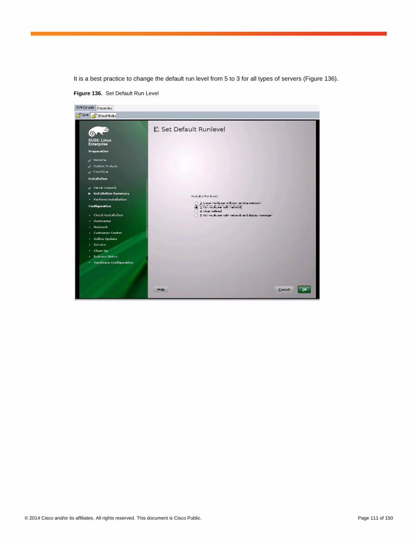
© 2014 Cisco and/or its affiliates. All rights reserved. This document is Cisco Public. Page 111 of 150
It is a best practice to change the default run level from 5 to 3 for all types of servers (Figure 136).
Figure 136. Set Default Run Level

© 2014 Cisco and/or its affiliates. All rights reserved. This document is Cisco Public. Page 112 of 150
You must select SAP HANA Server Base on the Software Selection and System Tasks screen, and Cisco
recommends that you deselect the GNOME Desktop Environment package on the same screen (Figure 137).
Figure 137. Software Selection

© 2014 Cisco and/or its affiliates. All rights reserved. This document is Cisco Public. Page 113 of 150
Figure 138 shows a summary page for this installation with the required software packages and the default run
level set to 3 instead or 5.
Figure 138. Installation Settings Summary: Software Packages

© 2014 Cisco and/or its affiliates. All rights reserved. This document is Cisco Public. Page 114 of 150
With the local disk boot option, the partitioning can be simple; use internal best practices to define the partitioning
that best fits your use case (Figure 139).
Figure 139. Installation Settings Summary: Partitioning for Local Disk Boot
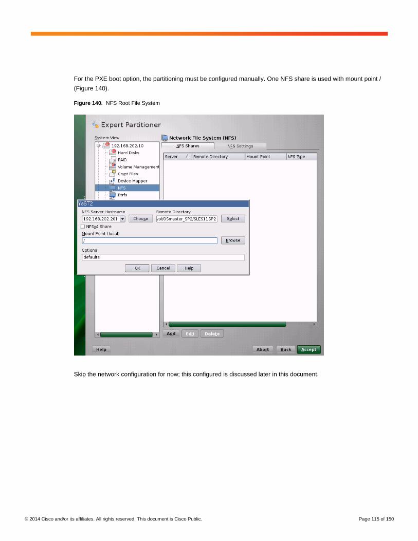
© 2014 Cisco and/or its affiliates. All rights reserved. This document is Cisco Public. Page 115 of 150
For the PXE boot option, the partitioning must be configured manually. One NFS share is used with mount point /
(Figure 140).
Figure 140. NFS Root File System
Skip the network configuration for now; this configured is discussed later in this document.

© 2014 Cisco and/or its affiliates. All rights reserved. This document is Cisco Public. Page 116 of 150
For a PXE boot, the NIC for the initial boot must be configured with DHCP (Figure 141). To identify the correct
interface, see the section “Network Configuration Options” later in this document.
Figure 141. Network Configuration
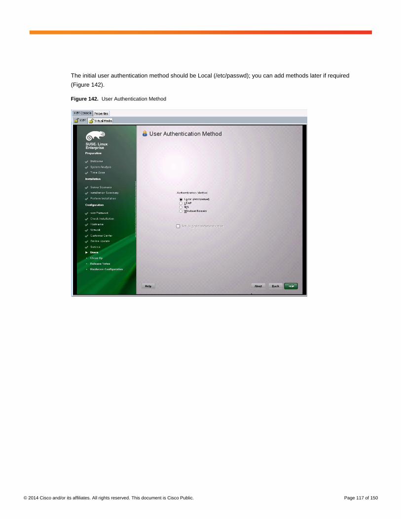
© 2014 Cisco and/or its affiliates. All rights reserved. This document is Cisco Public. Page 117 of 150
The initial user authentication method should be Local (/etc/passwd); you can add methods later if required
(Figure 142).
Figure 142. User Authentication Method
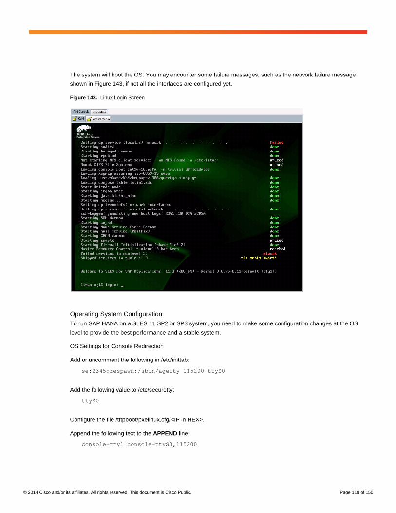
© 2014 Cisco and/or its affiliates. All rights reserved. This document is Cisco Public. Page 118 of 150
The system will boot the OS. You may encounter some failure messages, such as the network failure message
shown in Figure 143, if not all the interfaces are configured yet.
Figure 143. Linux Login Screen
Operating System Configuration
To run SAP HANA on a SLES 11 SP2 or SP3 system, you need to make some configuration changes at the OS
level to provide the best performance and a stable system.
OS Settings for Console Redirection
Add or uncomment the following in /etc/inittab:
se:2345:respawn:/sbin/agetty 115200 ttyS0
Add the following value to /etc/securetty:
ttyS0
Configure the file /tftpboot/pxelinux.cfg/<IP in HEX>.
Append the following text to the APPEND line:
console=tty1 console=ttyS0,115200

© 2014 Cisco and/or its affiliates. All rights reserved. This document is Cisco Public. Page 119 of 150
Here is an example of a modified /tftpboot/pxelinux.cdf/C0A87F5B file in SLES 11 SP2:
mgmtsrv01:/tftpboot/pxelinux.cfg # gethostip server01
server01 192.168.127.91 C0A87F5B
mgmtsrv01:/tftpboot/pxelinux.cfg # ls –l
lrwxrwxrwx 1 root root 8 Jan 25 09:11 192.168.127.91 -> C0A87F5B
-rw-r--r-- 1 root root 680 Feb 25 22:41 C0A87F5B
lrwxrwxrwx 1 root root 8 Jan 25 09:11 server01 -> C0A87F5B
mgmtsrv01:/tftpboot/pxelinux.cfg # cat C0A87F5B
# SAP UCS PXE Boot Definition
display ../boot.msg
default SLES11_SP2
prompt 1
timeout 10
LABEL SLES11_SP2
KERNEL vmlinuz-default
APPEND initrd=initrd_cisco.gz rw rootdev=192.168.127.11:/FS_OS_01/SLES11SP2
rootfsopts=default intel_idle.max_cstate=0 ip=dhcp console=tty1
console=ttyS0,115200 crashkernel=256M-:4G
With these settings, console redirection for SLES is configured (Figures 144 to 147).
Figure 144. Log Into Serial Console

© 2014 Cisco and/or its affiliates. All rights reserved. This document is Cisco Public. Page 120 of 150
Figure 145. Serial Console POST Screen
Figure 146. Serial Console Boot Menu
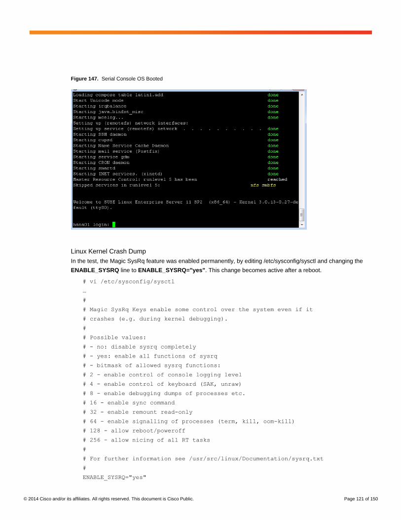
© 2014 Cisco and/or its affiliates. All rights reserved. This document is Cisco Public. Page 121 of 150
Figure 147. Serial Console OS Booted
Linux Kernel Crash Dump
In the test, the Magic SysRq feature was enabled permanently, by editing /etc/sysconfig/sysctl and changing the
ENABLE_SYSRQ line to ENABLE_SYSRQ="yes". This change becomes active after a reboot.
# vi /etc/sysconfig/sysctl
…
#
# Magic SysRq Keys enable some control over the system even if it
# crashes (e.g. during kernel debugging).
#
# Possible values:
# - no: disable sysrq completely
# - yes: enable all functions of sysrq
# - bitmask of allowed sysrq functions:
# 2 - enable control of console logging level
# 4 - enable control of keyboard (SAK, unraw)
# 8 - enable debugging dumps of processes etc.
# 16 - enable sync command
# 32 - enable remount read-only
# 64 - enable signalling of processes (term, kill, oom-kill)
# 128 - allow reboot/poweroff
# 256 - allow nicing of all RT tasks
#
# For further information see /usr/src/linux/Documentation/sysrq.txt
#
ENABLE_SYSRQ="yes"
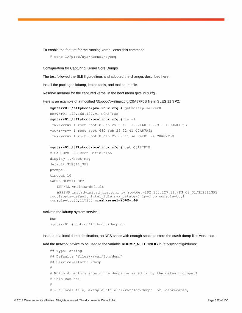
© 2014 Cisco and/or its affiliates. All rights reserved. This document is Cisco Public. Page 122 of 150
To enable the feature for the running kernel, enter this command:
# echo 1>/proc/sys/kernel/sysrq
Configuration for Capturing Kernel Core Dumps
The test followed the SLES guidelines and adopted the changes described here.
Install the packages kdump, kexec-tools, and makedumpfile.
Reserve memory for the captured kernel in the boot menu /pxelinux.cfg.
Here is an example of a modified /tftpboot/pxelinux.cfg/C0A87F5B file in SLES 11 SP2:
mgmtsrv01:/tftpboot/pxelinux.cfg # gethostip server01
server01 192.168.127.91 C0A87F5B
mgmtsrv01:/tftpboot/pxelinux.cfg # ls –l
lrwxrwxrwx 1 root root 8 Jan 25 09:11 192.168.127.91 -> C0A87F5B
-rw-r--r-- 1 root root 680 Feb 25 22:41 C0A87F5B
lrwxrwxrwx 1 root root 8 Jan 25 09:11 server01 -> C0A87F5B
mgmtsrv01:/tftpboot/pxelinux.cfg # cat C0A87F5B
# SAP UCS PXE Boot Definition
display ../boot.msg
default SLES11_SP2
prompt 1
timeout 10
LABEL SLES11_SP2
KERNEL vmlinuz-default
APPEND initrd=initrd_cisco.gz rw rootdev=192.168.127.11:/FS_OS_01/SLES11SP2
rootfsopts=default intel_idle.max_cstate=0 ip=dhcp console=tty1
console=ttyS0,115200 crashkernel=256M-:4G
Activate the kdump system service:
Run
mgmtsrv01:# chkconfig boot.kdump on
Instead of a local dump destination, an NFS share with enough space to store the crash dump files was used.
Add the network device to be used to the variable KDUMP_NETCONFIG in /etc/sysconfig/kdump:
## Type: string
## Default: "file:///var/log/dump"
## ServiceRestart: kdump
#
# Which directory should the dumps be saved in by the default dumper?
# This can be:
#
# - a local file, example "file:///var/log/dump" (or, deprecated,
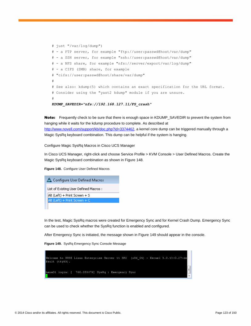
© 2014 Cisco and/or its affiliates. All rights reserved. This document is Cisco Public. Page 123 of 150
# just "/var/log/dump")
# - a FTP server, for example "ftp://user:passwd@host/var/dump"
# - a SSH server, for example "ssh://user:passwd@host/var/dump"
# - a NFS share, for example "nfs://server/export/var/log/dump"
# - a CIFS (SMB) share, for example
# "cifs://user:passwd@host/share/var/dump"
#
# See also: kdump(5) which contains an exact specification for the URL format.
# Consider using the "yast2 kdump" module if you are unsure.
#
KDUMP_SAVEDIR="nfs://192.168.127.11/FS_crash"
Note: Frequently check to be sure that there is enough space in KDUMP_SAVEDIR to prevent the system from
hanging while it waits for the kdump procedure to complete. As described at
http://www.novell.com/support/kb/doc.php?id=3374462, a kernel core dump can be triggered manually through a
Magic SysRq keyboard combination. This dump can be helpful if the system is hanging.
Configure Magic SysRq Macros in Cisco UCS Manager
In Cisco UCS Manager, right-click and choose Service Profile > KVM Console > User Defined Macros. Create the
Magic SysRq keyboard combination as shown in Figure 148.
Figure 148. Configure User Defined Macros
In the test, Magic SysRq macros were created for Emergency Sync and for Kernel Crash Dump. Emergency Sync
can be used to check whether the SysRq function is enabled and configured.
After Emergency Sync is initiated, the message shown in Figure 149 should appear in the console.
Figure 149. SysRq Emergency Sync Console Message
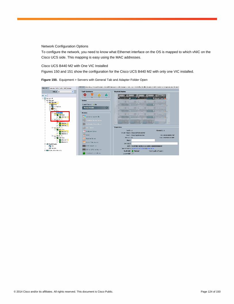
© 2014 Cisco and/or its affiliates. All rights reserved. This document is Cisco Public. Page 124 of 150
Network Configuration Options
To configure the network, you need to know what Ethernet interface on the OS is mapped to which vNIC on the
Cisco UCS side. This mapping is easy using the MAC addresses.
Cisco UCS B440 M2 with One VIC Installed
Figures 150 and 151 show the configuration for the Cisco UCS B440 M2 with only one VIC installed.
Figure 150. Equipment > Servers with General Tab and Adapter Folder Open
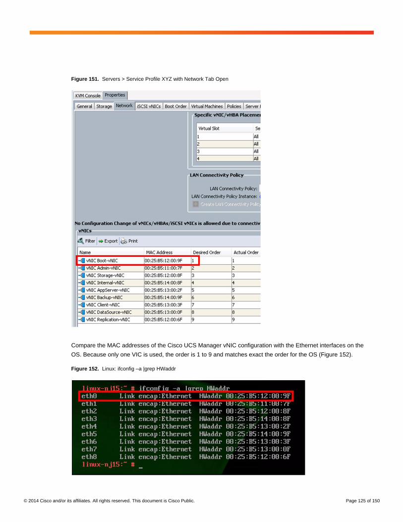
© 2014 Cisco and/or its affiliates. All rights reserved. This document is Cisco Public. Page 125 of 150
Figure 151. Servers > Service Profile XYZ with Network Tab Open
Compare the MAC addresses of the Cisco UCS Manager vNIC configuration with the Ethernet interfaces on the
OS. Because only one VIC is used, the order is 1 to 9 and matches exact the order for the OS (Figure 152).
Figure 152. Linux: ifconfig –a |grep HWaddr

© 2014 Cisco and/or its affiliates. All rights reserved. This document is Cisco Public. Page 126 of 150
Cisco UCS B440 M2 with Two VICs Installed
Figure 153 shows the configuration for the Cisco UCS B440 M2 with two VICs installed.
Figure 153. Equipment > Servers with General Tab Open

© 2014 Cisco and/or its affiliates. All rights reserved. This document is Cisco Public. Page 127 of 150
In Figure 154, the Actual Placement column shows the VIC to which the vNIC is mapped, and the Actual Order
column shows the order for each VIC. Note that SLES uses the order when scanning the PCI subsystem and will
pick the second VIC before the first VIC.
Figure 154. Servers > Service Profile XYZ with Network Tab Open

© 2014 Cisco and/or its affiliates. All rights reserved. This document is Cisco Public. Page 128 of 150
As Figure 155 shows, eth0 has the MAC address 00:25:B5:14:00:AF, which is used by the backup vNIC placed on
VIC 2 followed by the client vNIC with MAC address 00:25:B5:13:00:5F.
Figure 155. Linux: ifconfig –a |grep HWaddr
This behavior is important to know if the OS installation or configuration is automated using a deployment or
workflow tool.
Configure the Default Router
Add the required entry in /etc/sysconfig/network/routes:
default <ROUTER IP> - -
Disable Transparent Hugepages
With SLES 11 SP2, the use of transparent hugepages, or THP, is generally activated for the Linux kernel. THP
allows multiple pages to be handled as hugepages, reducing the translation lookaside buffer (TLB) footprint in
situations in which this may be useful. Because of the way that SAP HANA manages memory, the use of THP may
lead to system hang and performance degradation.
To disable the use of THP, specify the kernel settings at runtime as follows:
echo never > /sys/kernel/mm/transparent_hugepage/enabled
You do not need to shut down the database to apply this configuration. This setting is then valid until the next
system start. To make this option persistent, integrate this command line into your system boot scripts (for
example, /etc/init.d/after.local).
Configure C States for Lower Latency in Linux
Linux Kernel 3.0 includes a new cpuidle driver for recent Intel CPUs: intel_idle. This driver leads to a different
behavior in C-state switching. The normal operating state is C0, and when the processor is placed in a higher C
state, it will save power. However, for low-latency applications, the additional time needed to begin processing the
code again will cause performance degradation.
© 2014 Cisco and/or its affiliates. All rights reserved. This document is Cisco Public. Page 129 of 150
Therefore, you should edit the boot loader configuration. The location of the boot loader configuration file is
usually /etc/sysconfig/bootloader. Edit this file and append the following value to the DEFAULT_APPEND
parameter value:
intel_idle.max_cstate=0
This command implements a persistent change for potential kernel upgrades and boot loader upgrades. For an
immediate configuration change, you also need to append this parameter in the kernel command line of your
current active boot loader file, which is located on the PXE server under /tftpboot/pxelinux.cfg.
Append the intel_idle value mentioned earlier only to the operational kernel's parameter line.
The C states are disabled in the BIOS, but to be sure that the C states are not used, set the following parameter in
addition to the previous one:
processor.max_cstate=0
The CPU speed must be set to performance for SAP HANA so that all cores run all the time with
highest frequency:
/usr/bin/cpupower frequency-set –g performance 2>&1
To make this option persistent, integrate this command line into your system boot scripts (for example,
/etc/init.d/after.local).
Configure Swappiness
Set swappiness to 30 to avoid swapping:
Echo 30 > /proc/sys/vm/swappiness
Configure RSS and RPS Settings in the OS
To get use of the RSS setting in the adapter policy, you must configure RPS at the OS level.
RPS distributes the load of received packet processing across multiple CPUs. Note that protocol processing
performed in the NAPI context for received packets is serialized per device queue and becomes a bottleneck under
high packet load. This characteristic substantially limits the pps rate that can be achieved on a single queue NIC
and provides no scaling for multiple cores.
In the test, the best performance results were achieved with the following setting:
echo 3ff > /sys/class/net/${ethernet_device}/queues/rx-0/rps_cpus
Replace ${Ethernet_device} with all the Ethernet devices for which you need high throughput. Here are
some examples:
echo 3ff > /sys/class/net/eth0/queues/rx-0/rps_cpus
echo 3ff > /sys/class/net/eth1/queues/rx-0/rps_cpus
echo 3ff > /sys/class/net/eth2/queues/rx-0/rps_cpus
echo 3ff > /sys/class/net/eth3/queues/rx-0/rps_cpus

© 2014 Cisco and/or its affiliates. All rights reserved. This document is Cisco Public. Page 130 of 150
To make this option persistent, integrate this command line into your system boot scripts (for example,
/etc/init.d/after.local).
Configure Hostname
The operating system must be configured so that the short name of the server appears if command hostname is
used. The fully qualified hostname is displayed when the command hostname–d is used.
Configure Network Time
The time on all components used for SAP HANA should be the same. The configuration of NTP is important and
should be performed on all systems.
cishanar01:~ # cat /etc/ntp.conf
server <NTP-SERVER IP>
fudge <NTP-SERVER IP> stratum 10
keys /etc/ntp.keys
trustedkey 1
Configure Domain Name Service
The Domain Name Service (DNS) configuration must be performed based on local requirements. Here is a sample
configuration:
cishana07:/etc/sysconfig # vi /etc/resolv.conf
search cisco-hana.corp
nameserver 10.17.121.30
nameserver 10.17.122.10
Configure SSH Keys
SSH keys must be exchanged between all nodes in a SAP HANA scale-out system for the user root and the user
<SID>adm.
cishanar01:~/.ssh # ssh-keygen –b 2048
Generating public/private rsa key pair.
Enter file in which to save the key (/root/.ssh/id_rsa):
Enter passphrase (empty for no passphrase):
Enter same passphrase again:
Your identification has been saved in /root/.ssh/id_rsa.
Your public key has been saved in /root/.ssh/id_rsa.pub.
The key fingerprint is:
fb:66:0f:8d:fc:40:f7:c1:e6:15:46:6e:ec:5f:7d:af hadmin@mgmtsrv01

© 2014 Cisco and/or its affiliates. All rights reserved. This document is Cisco Public. Page 131 of 150
The key's randomart image is:
+--[ RSA 2048]----+
| . |
| + |
| * |
| .+ o |
| S . . +.= |
| + + + o= |
| . = . o o |
| .o+ . |
| o..o E |
+-----------------+
cishanar01:~/.ssh #
cishanar01:~/.ssh # cat id_rsa.pub
ssh-rsa
AAAAB3NzaC1yc2EAAAABIwAAAQEAuqcSAZk01nGWYpwsqgAfb4j1p0zOx4axwdFDlwa2rqRTvZ
yMIqW8ajtkiQaUInSTknUhQuaBlN90GPz9u5bkgJG8xJ7U/1l8xwd/q6NbCocJRyNIYq5JvohFmoOFb/Q
rEWhwugdGg/lEefFRPHltJm
v/wqfRgaUovf/t3Tn99gBkQIYdBEe5FoW7xx+4tt4SINjj/I8VXVS7fVRLshR7cjHHLekEzAY+g6p+tQh
yfZQ1yR1dS12wDs4UeAjcD1
6JaiJUeAb35dg/5ai3I+tLyBtOcoXuJvm0kmv7mVb925FbG1mOCXqzI1HeonQTsPbxnXw6tup7Lq+oZaK
EoZQIpQ== root@mgmtsrv01
cishanar01:~/.ssh #
cishanar01:~ # ssh-copy-id -i /root/.ssh/id_rsa.pub <OTHER HANA NODES>
Password: ********
…
Configure Sudoers
The Fibre Channel client (fcClient) requires configuration changes to run properly. These changes are performed in
the SAP HANA installation procedure.
Configure Syslog
For centralized monitoring of all SAP HANA nodes, configure syslog-ng to forward all messages to an central
syslog server.
Change the syslog-ng.conf file as follows:
cishanar02:~ # vi /etc/syslog-ng/syslog-ng.conf
…
…
…
#
# Enable this and adopt IP to send log messages to a log server.
#
destination logserver1 { udp("<SYSLOG-SERVER IP>" port(<SYSLOG-Server PORT>)); };
log { source(src); destination(logserver1); };

© 2014 Cisco and/or its affiliates. All rights reserved. This document is Cisco Public. Page 132 of 150
destination logserver2 { udp("<SYSLOG-SERVER IP>" port(<SYSLOG-Server PORT>)); };
log { source(src); destination(logserver2); };
…
…
Now restart the syslog daemon:
cishanar02:~ # /etc/init.d/syslog restart
Storage Access for SAP HANA
This section presents basic information about the configuration of SAP HANA storage at the OS level. The
underlying infrastructure configuration is discussed earlier in this document.
The information presented here describes examples based on the Cisco solution for SAP HANA and provides only
a high-level overview on the configuration process. You must work with your storage vendor to define the best
configuration based on your storage model and use case.
Block Storage for SAP HANA Data and Log Files
The block storage configuration in the OS for data and log files is the same for all Fibre Channel solutions
regardless of whether the traffic traverses native Fibre Channel or FCoE.
Linux Multipathing
For block storage, you should use a multipath configuration. This section shows an example of this configuration
using the Cisco and EMC solution for SAP HANA and native Linux multipathing (device manager multipath I/O
[DM-MPIO]) on the SAP HANA nodes to improve performance and provide high availability for the access paths to
the storage devices.
Figure 156 shows the multipath relationship of a LUN in the storage array and its corresponding single-path and
multipath devices on the SAP HANA node.
Figure 156. DM-MPIO with Persistent Group Reservation (PGR) on EMC VNX5300

© 2014 Cisco and/or its affiliates. All rights reserved. This document is Cisco Public. Page 133 of 150
A LUN in the EMC VNX array belongs to one storage processor (the default storage processor) but can move
(trespass) to the other storage processor if the default storage processor fails. Each storage processor has four
Fibre Channel I/O ports (ports 4 to 7). On the other side, each SAP HANA node has two vHBAs (vHBA1 and
vHBA2), with each vHBA having two paths to each storage processor. Therefore, there are four active paths from
the SAP HANA node to each LUN, and four enabled paths. The enabled paths will become active if a trespass of
the LUN in the storage array occurs.
On the host, the LUN is visible over eight paths—four active and four enabled paths—and is represented by a
single device for each path: for example, /dev/sdar. The single devices are combined into a multipath device: dm-2.
The following multipath command illustrates the example in Figure 156:
$ multipath –ll
3600601603fa02900a0e80ccf671ee111 dm-6 DGC,VRAID
size=2.0T features='1 queue_if_no_path' hwhandler='1 emc' wp=rw
|-+- policy='round-robin 0' prio=4 status=active
| |- 2:0:4:3 sdx 65:112 active ready running
| |- 2:0:5:3 sdag 66:0 active ready running
| |- 1:0:2:3 sdar 66:176 active ready running
| `- 1:0:3:3 sdba 67:64 active ready running
`-+- policy='round-robin 0' prio=1 status=enabled
|- 2:0:2:3 sdf 8:80 active ready running
|- 2:0:3:3 sdo 8:224 active ready running
|- 1:0:4:3 sdbj 67:208 active ready running
`- 1:0:5:3 sdbs 68:96 active ready running
The specific configuration requirements depend on the storage vendor and model and must be provided by the
storage vendor.
Fdisk
In most cases, one partition per LUN and no volume management is used. The exact partitioning and configuration
must be defined with the storage vendor based on the storage model and the use case.
File System Type
To specify the file system to use for the SAP HANA data and log volumes, consult the storage vendor to determine
the best performance and availability.
The recommended approach is to use the storage connector API for the SAP HANA data and log volumes and not
/etc/fstab. Check with the storage vendor to learn how the volumes are operated: with fstab or global.ini.
Global.ini
The SAP HANA storage connector API for block storage is responsible for remounting and I/O fencing of the SAP
HANA persistent layer. It must be used in a SAP HANA scale-out installation in which the persistence resides on
block-attached storage devices.
The API is implemented by enabling the appropriate entry in the SAP HANA global.ini file. This file resides in the
/hanamnt/shared/>SID>/global/hdb/custom/config directory.
An example of a global.ini file for EMC VNX storage is shown here:
© 2014 Cisco and/or its affiliates. All rights reserved. This document is Cisco Public. Page 134 of 150
[persistence]
use_mountpoints = yes
basepath_datavolumes = /hana/data/ANA
basepath_logvolumes = /hana/log/ANA
basepath_shared=yes
[storage]
ha_provider = hdb_ha.fcClient
partition_*_*__prType = 5
partition_1_data__wwid = 3600601603fa02900bad499d33b02e211
partition_1_log__wwid = 3600601603fa0290072085bfb3e02e211
partition_2_data__wwid = 3600601603fa0290044191eb83b02e211
partition_2_log__wwid = 3600601603fa02900ba553c933f02e211
partition_3_data__wwid = 3600601603fa02900cc468dee3f02e211
partition_3_log__wwid = 3600601603fa02900b8a136174002e211
partition_4_data__wwid = 3600601603fa02900ec2412d53f02e211
partition_4_log__wwid = 3600601603fa0290070aa76024002e211
For the exact configuration of the [storage] section in the global.ini file, you must consult the storage vendor.
File Storage for SAP HANA Data and Log Files
High-Availability Configuration
Since SAP HANA Revision 35, the ha_provider python class supports the STONITH function. With this Python
class, you can reset the failing node to prevent a “split brain” and thus an inconsistency in the database. Even with
NFSv4, there is some minimal, theoretical risk that such a situation may occur. A reset of the failed node eliminates
this theoretical risk.
Here as an example of a configuration for ucs_ha_class.py and ucs_ipmi_reset.sh:
cishanar01:/ # cd /hana/shared
cishanar01:/hana/shared # mkdir scripts
cishanar01:/hana/shared # cd scripts
cishanar01:/hana/shared/scripts # vi ucs_ha_class.py
"""
Function Class to call the reset program to kill the failed host and remove NFS
locks for the SAP HANA HA
Class Name ucs_ha_class
Class Phath /usr/sap/<SID>/HDB<ID>/exe/python_support/hdb_ha
"""
from client import StorageConnectorClient
import os
class ucs_ha_class(StorageConnectorClient):
def __init__(self, *args, **kwargs):
super(ucs_ha_class, self).__init__(*args, **kwargs)

© 2014 Cisco and/or its affiliates. All rights reserved. This document is Cisco Public. Page 135 of 150
def stonith(self, hostname):
os.system ("/bin/logger STONITH HANA Node:" + hostname)
os.system ("/hana/shared/scripts/ucs_ipmi_reset.sh " + hostname)
def about(self):
ver={"provider_company":"Cisco",
"provider_name" :"ucs_ha_class",
"provider_version":"0.1",
"api_version" :1}
self.tracer.debug('about: %s'+str(ver))
print '>> ha about',ver
return ver
def sudoers():
return """ALL:NOPASSWD: /bin/mount, /bin/umount, /bin/logger"""
def attach(self,storages):
pass
def detach(self, storages):
pass
def info(self, paths):
pass
cishanar01:/hana/shared/scripts #
cishanar01:/hana/shared/scripts #
cishanar01:/hana/shared/scripts # vi ucs_ipmi_reset.sh
#!/bin/bash
# SAP HANA High Availability
# Version 1.0 08/2012
if [ -z $1 ]
then
exit 1
fi
/bin/logger `whoami`" Resetting the HANA Node $1 because of an
Nameserver reset command"
# use the ipmitool to send a power reset to <hostname>-ipmi
/usr/bin/ipmitool -H $1-ipmi -U <IPMI-User> -P <IPMI-Password> power reset
# If required add the required commands to release the NFS-Locks
# on the storage. Here an example for EMC VNX
# /opt/EMC/release_lock -y -f $1 <EMC Control-Station IP>
/bin/logger `whoami`" Release NFS locks of HANA Node $1"
rc=$?
© 2014 Cisco and/or its affiliates. All rights reserved. This document is Cisco Public. Page 136 of 150
exit $rc
cishanar01:/hana/shared/scripts #
cishanar01:/hana/shared/scripts #
Link the high-availability scripts to the shared high-availability (HA) directory under /usr/sap/<SID>/HDB<NR>/HA
(remember that the SAP HANA name server is responsible for resetting the failed node):
cishanar01:/ # mkdir /usr/sap/<SID>/HDB<NR>/HA
cishanar01:/ # chown <SID>adm:sapsys /usr/sap/<SID>/HDB<NR>/HA
cishanar01:/ # cd
cishanar01:/usr/sap/<SID>/HDB<NR>/HA # ln –s /hana/shared/scripts/ucs_ha_class.py
cishanar01:/usr/sap/<SID>/HDB<NR>/HA # ln –s
/hana/shared/scripts/ucs_ipmi_reset.sh
cishanar01:/usr/sap/<SID>/HDB<NR>/HA # chown <SID>adm:sapsys *
Link the HA directory to the correct SID and system ID location (on all nodes):
cishanar01: # cd /usr/sap
cishanar01:/usr/sap # ln -s ./T01/HDB00/HA
cishanar02: # cd /usr/sap
cishanar02:/usr/sap # ln -s ./T01/HDB00/HA
cishanar03: # cd /usr/sap
cishanar03:/usr/sap # ln -s ./T01/HDB00/HA
cishanar04: # cd /usr/sap
cishanar04:/usr/sap # ln -s ./T01/HDB00/HA
Global.ini
The SAP HANA storage connector API provides a way to call a user procedure whenever the SAP HANA name
server triggers a node failover. The API requires the files mentioned in the preceding section. The procedure is run
on the SAP HANA master name server.
To activate the procedure in the event of a node failover, you must edit the global.ini file in
<HANA install directory>/<SID>/global/hdb/custom/config/ and add the following entry:
[Storage]
ha_provider = ucs_ha_class
cishana01: # cd /hanamnt/shared/<SID>/global/hdb/custom/config
cishana01:/hanamnt/shared/ANA/global/hdb/custom/config # ls -l
-rw-r----- 1 anaadm sapsys 90 Feb 15 11:22 global.ini
-rw-rw-r-- 1 anaadm sapsys 9560 Feb 15 11:23 hdbconfiguration_1
drwxr-x--- 3 anaadm sapsys 4096 Feb 15 11:22 lexicon
-rw-r--r-- 1 anaadm sapsys 128 Feb 15 12:34 nameserver.ini
© 2014 Cisco and/or its affiliates. All rights reserved. This document is Cisco Public. Page 137 of 150
cishana01:/hanamnt/shared/ANA/global/hdb/custom/config #
cishana01:/hanamnt/shared/ANA/global/hdb/custom/config # vi global.ini
[persistence]
basepath_datavolumes=/hanamnt/data/ANA
basepath_logvolumes=/hanamnt/log/ANA
[storage]
ha_provider = ucs_ha_class
ha_provider_path = /usr/sap/HA
Restart the SAP HANA database to activate the changes.
Check with your storage vendor to determine whether any other settings are required for the storage model you
are using.
Mount Options
To use NFS for SAP HANA data and log volumes, you need to change the mount options from the default Linux
settings. Here an example of an fstab entry for NFSv4:
<NFS-Server>:/<NFS-Share> /hana/data/<SID>/mnt<NR> nfs4
rw,bg,vers=4,hard,rsize=65536,wsize=65536,nointr,actimeo=0,lock 0 0
Make sure that the <SID>adm user owns the data and log volumes; use the chown command after the file systems
are mounted.
Check with the storage vendor to learn what settings are required for the storage model you are using.
Block Storage for SAP HANA Shared File System
OCFS2
To use Oracle Cluster File System 2 (OCFS2) for the SAP HANA shared file system, you need to install and
configure a cluster service.
Here is the link to the SUSE documentation:
https://www.suse.com/documentation/sle_ha/singlehtml/book_sleha/book_sleha.html#cha.ha.ocfs2.
Note: The size of the /hana/shared file system must be at least equal to the main memory of all SAP HANA
nodes, and the file system type must be able to expand the size if a new node is added to the SID. To shrink file
systems on a block device, or to shrink the block device itself, in most cases you need to delete and re-create the
file system or block device.
File Storage for /hana/shared
The SAP HANA data and log volumes are based on a shared-nothing model. In addition, SAP HANA requires a
shared area in which all SAP HANA nodes for one SID have access all time in parallel: /hana/shared/<SID>.

© 2014 Cisco and/or its affiliates. All rights reserved. This document is Cisco Public. Page 138 of 150
Here a sample fstab entry:
<NFS-Server>:/<NFS-Share> /hana/shared nfs4
rw,bg,vers=4,hard,rsize=65536,wsize=65536,nointr,actimeo=0,nolock 0 0
Note: The size of the /hana/shared file system must be at least equal to the main memory of all SAP HANA
nodes, and the file system type must be able to expand the size if a new node is added to the SID. One benefit of
NFS in most cases is the capability to shrink the file system on demand without any downtime.
Cisco UCS Solution for SAP HANA TDI: Shared Network
This section describes the Cisco UCS solution for the SAP HANA TDI implementation option for a shared network.
With the introduction of SAP HANA TDI for shared networks, the Cisco solution can provide the benefits of an
integrated computer and network stack in combination with the programmability of Cisco UCS.
The SAP HANA TDI option enables organizations to run multiple SAP HANA production systems in one Cisco
solution, creating an appliance-like solution. Many customers already use this option for their nonproduction
systems. Another option is to run the SAP application server using the SAP HANA database on the same
infrastructure as the SAP HANA database.
In addition to these two options, you can also install a SAP HANA database in an existing Cisco UCS deployment
used to run SAP and non-SAP applications.
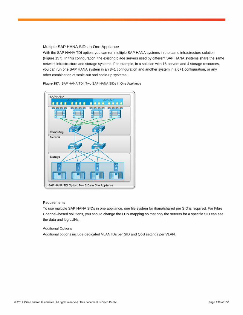
© 2014 Cisco and/or its affiliates. All rights reserved. This document is Cisco Public. Page 139 of 150
Multiple SAP HANA SIDs in One Appliance
With the SAP HANA TDI option, you can run multiple SAP HANA systems in the same infrastructure solution
(Figure 157). In this configuration, the existing blade servers used by different SAP HANA systems share the same
network infrastructure and storage systems. For example, in a solution with 16 servers and 4 storage resources,
you can run one SAP HANA system in an 8+1 configuration and another system in a 6+1 configuration, or any
other combination of scale-out and scale-up systems.
Figure 157. SAP HANA TDI: Two SAP HANA SIDs in One Appliance
Requirements
To use multiple SAP HANA SIDs in one appliance, one file system for /hana/shared per SID is required. For Fibre
Channel–based solutions, you should change the LUN mapping so that only the servers for a specific SID can see
the data and log LUNs.
Additional Options
Additional options include dedicated VLAN IDs per SID and QoS settings per VLAN.

© 2014 Cisco and/or its affiliates. All rights reserved. This document is Cisco Public. Page 140 of 150
SAP HANA and SAP Application Server in One Appliance
You can run the SAP HANA–related SAP application server on the same infrastructure as the SAP HANA
database (Figure 158). With this configuration, the solution controls the communication between the application
server and the database. This approach quarantines the bandwidth and latency for best performance and includes
the application server in the disaster tolerance solution together with the SAP HANA database.
Figure 158. SAP HANA TDI: Database and Application in One Appliance
Requirements
To use SAP HANA and the SAP application server in one appliance, a dedicated server for the SAP applications is
required. You can use the same server type as for the SAP HANA database (Cisco UCS B440 M2), or you can add
servers such as the Cisco UCS B200 M3 Blade Server, to run the application directly on the blade or as a
virtualized system with a supported hypervisor.
The storage for the OS and application can be hosted on the same external storage as used for SAP HANA.
However, this setup can degrade the performance of the SAP HANA databases on this storage, so separate
storage is recommended.
Additional Options
Additional options include dedicated VLAN IDs and QoS settings per VLAN. You can introduce a dedicated
application to the database network based on VLAN separation.

© 2014 Cisco and/or its affiliates. All rights reserved. This document is Cisco Public. Page 141 of 150
SAP HANA in an Existing Cisco UCS Deployment
You can deploy SAP HANA in an existing Cisco UCS deployment (Figure 159). In the example here, a FlexPod
solution is used to show how this option works. The FlexPod infrastructure is built from the same components as
the Cisco and NetApp solution for SAP HANA. Therefore, you can run one or more SAP HANA instances within a
FlexPod system, following these rules:
● Use only certified servers for SAP HANA.
● The network bandwidth per server must meet the guidelines described earlier.
● The storage must pass the test tool for SAP HANA TDI shared storage.
Figure 159. SAP HANA TDI: SAP HANA in a FlexPod Solution
Requirements
To deploy SAP HANA in an existing Cisco UCS deployment, a dedicated server for SAP HANA is required, with 10
Gigabit Ethernet for each node for SAP HANA internal traffic.
The storage for the OS and SAP HANA can be hosted on the same external storage resource as for all
other applications, as long the KPIs for SAP HANA TCI shared storage are met. However, separate storage
is recommended.
Additional Options
Additional options include dedicated VLAN IDs and QoS settings per VLAN.

© 2014 Cisco and/or its affiliates. All rights reserved. This document is Cisco Public. Page 142 of 150
Conclusion
There are a wide variety of ways to connect external storage to Cisco UCS. The long-standing industry best
practices for Fibre Channel, FCoE, iSCSI, and NFS and CIFS apply with no changes for Cisco UCS unless the
user wants to deploy a direct-connect topology with Cisco UCS and the storage. Using both NetApp and Cisco
UCS with best practices for both results in reliable, flexible, and scalable computing and storage infrastructure.
For More Information
Cisco UCS Manager GUI Configuration Guides
Cisco UCS B-series OS Installation Guides
SAP HANA at Cisco.com
Central SAP HANA page
Central SAP HANA Support page
Appendix: Direct-Attached NFS Failure Scenarios
This section will presents failure scenarios using NetApp FAS storage in the examples. Check with your storage
vendor to learn how to configure network failover for your storage.
Network-Attached Storage and Cisco UCS Appliance Ports
When you use NFS or Common Internet File System (CIFS) with appliance ports, you must have upstream Layer 2
Ethernet switching to allow traffic to flow in certain failure scenarios. This requirement is not needed for iSCSI-only
traffic given the use of the host MPIO stack, which manages path failures and recovery end to end.
Appliance ports were introduced in Cisco UCS 1.4 and were designed to allow direct connection between the Cisco
UCS fabric interconnect and the NetApp storage controller. An appliance port is essentially a server port that also
performs MAC address learning. Given that the appliance port is a server port, the same uplink and border port
policies apply to them. They have border ports associated with them, and a network control policy determines what
happens in the event that the last available border or uplink port fails.
Appliance ports, like server ports, have uplink or border ports assigned either through static or dynamic pinning. By
default, if the last uplink port fails, the appliance port will be taken down. You can change the network control policy
for the appliance to make this event trigger a warning only. For NFS configurations, you should use the default
setting, which takes down the appliance port if the last uplink port fails. This setting helps ensure more
deterministic failover in the topology.
Cisco UCS fabric interconnects cannot run on vPC peers, so for Cisco UCS fabric interconnects, there is an active-
passive data path for NFS traffic to the same IP address. You can, of course, perform active-active I/O from both
fabric interconnects to different back-end NetApp volumes and controllers.
You should use the interface group (ifgrp) feature to manage Ethernet ports on the NetApp controller. This feature
was called the virtual interface (VIF) feature in earlier releases of NetApp Data ONTAP. There are single-mode
ifgrps and multimode ifgrps. Single-mode ifgrps are active-standby interfaces, and multimode ifgrps can be static or
dynamic and support LACP PortChannels. For a detailed description of this feature, see the NetApp Data ONTAP
Network Management Guide.
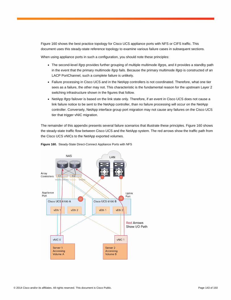
© 2014 Cisco and/or its affiliates. All rights reserved. This document is Cisco Public. Page 143 of 150
Figure 160 shows the best practice topology for Cisco UCS appliance ports with NFS or CIFS traffic. This
document uses this steady-state reference topology to examine various failure cases in subsequent sections.
When using appliance ports in such a configuration, you should note these principles:
● The second-level ifgrp provides further grouping of multiple multimode ifgrps, and it provides a standby path
in the event that the primary multimode ifgrp fails. Because the primary multimode ifgrp is constructed of an
LACP PortChannel, such a complete failure is unlikely.
● Failure processing in Cisco UCS and in the NetApp controllers is not coordinated. Therefore, what one tier
sees as a failure, the other may not. This characteristic is the fundamental reason for the upstream Layer 2
switching infrastructure shown in the figures that follow.
● NetApp ifgrp failover is based on the link state only. Therefore, if an event in Cisco UCS does not cause a
link failure notice to be sent to the NetApp controller, than no failure processing will occur on the NetApp
controller. Conversely, NetApp interface group port migration may not cause any failures on the Cisco UCS
tier that trigger vNIC migration.
The remainder of this appendix presents several failure scenarios that illustrate these principles. Figure 160 shows
the steady-state traffic flow between Cisco UCS and the NetApp system. The red arrows show the traffic path from
the Cisco UCS vNICs to the NetApp exported volumes.
Figure 160. Steady-State Direct-Connect Appliance Ports with NFS

© 2014 Cisco and/or its affiliates. All rights reserved. This document is Cisco Public. Page 144 of 150
Failure Scenario 1: Cisco UCS Fabric Interconnect Fails (Simplest Failure Case)
In Figure 161, the Cisco UCS fabric interconnect on the left fails. Cisco UCS will see this as a situation in which
the vNIC is moved from the A side to the B side by the fabric failover feature. No problems are encountered in this
scenario as the traffic fails over to the standby VIF because NetApp sees the fabric interconnect failure as a link-
down event on the primary interface and thus expects to start seeing traffic on the standby interface and
accepting it.
Figure 161. Failure Scenario 1: Fabric Interconnect Is Lost

© 2014 Cisco and/or its affiliates. All rights reserved. This document is Cisco Public. Page 145 of 150
Recovery from Failure Scenario 1: Fabric Interconnect Is Repaired and Rebooted
When the fabric interconnect on the left comes back online, the traffic will not automatically go back to the steady
state unless you use the NetApp Favor option when configuring the VIF interfaces. Use of this option is considered
a best practice and should always be implemented. If this option is not used, then the traffic will flow through the
upstream Layer 2 infrastructure as shown in Figure 162. Recall that the appliance ports perform MAC address
learning and have associated uplink ports, which is the reason that this traffic pattern is able to flow.
Figure 162. Data Path Upon Recovery of Fabric Interconnect
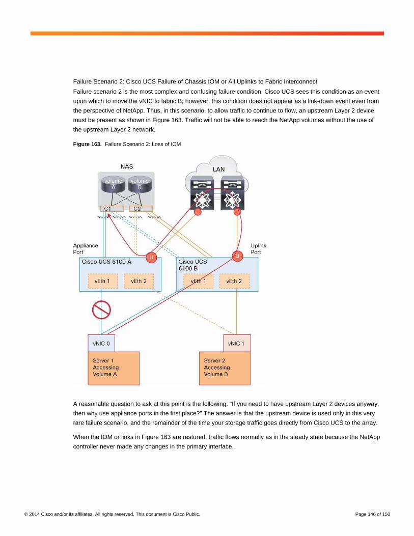
© 2014 Cisco and/or its affiliates. All rights reserved. This document is Cisco Public. Page 146 of 150
Failure Scenario 2: Cisco UCS Failure of Chassis IOM or All Uplinks to Fabric Interconnect
Failure scenario 2 is the most complex and confusing failure condition. Cisco UCS sees this condition as an event
upon which to move the vNIC to fabric B; however, this condition does not appear as a link-down event even from
the perspective of NetApp. Thus, in this scenario, to allow traffic to continue to flow, an upstream Layer 2 device
must be present as shown in Figure 163. Traffic will not be able to reach the NetApp volumes without the use of
the upstream Layer 2 network.
Figure 163. Failure Scenario 2: Loss of IOM
A reasonable question to ask at this point is the following: "If you need to have upstream Layer 2 devices anyway,
then why use appliance ports in the first place?" The answer is that the upstream device is used only in this very
rare failure scenario, and the remainder of the time your storage traffic goes directly from Cisco UCS to the array.
When the IOM or links in Figure 163 are restored, traffic flows normally as in the steady state because the NetApp
controller never made any changes in the primary interface.
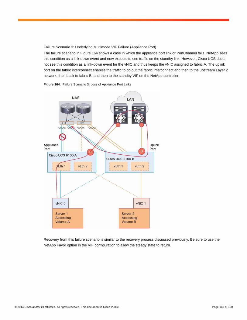
© 2014 Cisco and/or its affiliates. All rights reserved. This document is Cisco Public. Page 147 of 150
Failure Scenario 3: Underlying Multimode VIF Failure (Appliance Port)
The failure scenario in Figure 164 shows a case in which the appliance port link or PortChannel fails. NetApp sees
this condition as a link-down event and now expects to see traffic on the standby link. However, Cisco UCS does
not see this condition as a link-down event for the vNIC and thus keeps the vNIC assigned to fabric A. The uplink
port on the fabric interconnect enables the traffic to go out the fabric interconnect and then to the upstream Layer 2
network, then back to fabric B, and then to the standby VIF on the NetApp controller.
Figure 164. Failure Scenario 3: Loss of Appliance Port Links
Recovery from this failure scenario is similar to the recovery process discussed previously. Be sure to use the
NetApp Favor option in the VIF configuration to allow the steady state to return.

© 2014 Cisco and/or its affiliates. All rights reserved. This document is Cisco Public. Page 148 of 150
Failure Scenario 4: Last Uplink on Cisco UCS Fabric Interconnect Fails
As of Cisco UCS Release 1.4(3), this failure scenario is identical the failure of a fabric interconnect as shown in
failure scenario 1. The default policy is to bring down the appliance ports if the last uplink is down (Figure 165).
Figure 165. Failure Scenario 4: Loss of Last Uplink Port on Fabric Interconnect
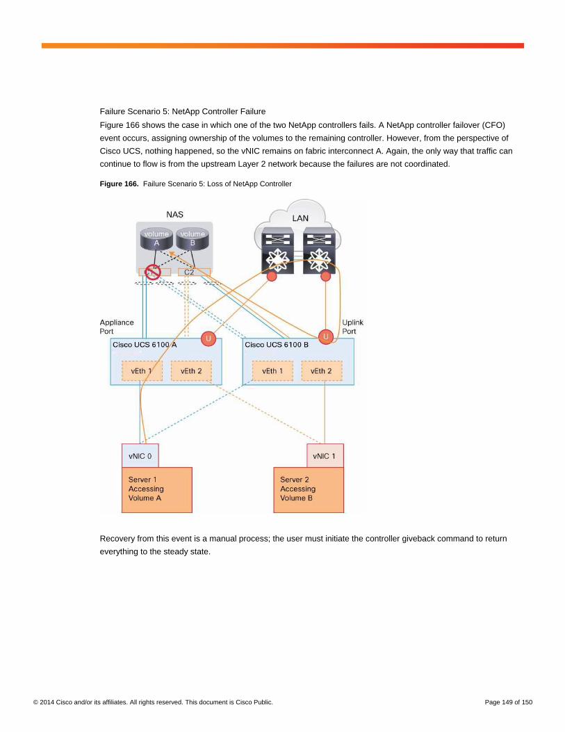
© 2014 Cisco and/or its affiliates. All rights reserved. This document is Cisco Public. Page 149 of 150
Failure Scenario 5: NetApp Controller Failure
Figure 166 shows the case in which one of the two NetApp controllers fails. A NetApp controller failover (CFO)
event occurs, assigning ownership of the volumes to the remaining controller. However, from the perspective of
Cisco UCS, nothing happened, so the vNIC remains on fabric interconnect A. Again, the only way that traffic can
continue to flow is from the upstream Layer 2 network because the failures are not coordinated.
Figure 166. Failure Scenario 5: Loss of NetApp Controller
Recovery from this event is a manual process; the user must initiate the controller giveback command to return
everything to the steady state.
© 2014 Cisco and/or its affiliates. All rights reserved. This document is Cisco Public. Page 150 of 150
Summary of Failure Recovery Principles
Here is a summary of the main principles when using appliance ports for NFS traffic with NetApp arrays:
● You must have Layer 2 Ethernet upstream for failure cases; you cannot just deploy a storage array and
Cisco UCS hardware.
● Always enable an IP storage VLAN on the fabric interconnect uplinks for data traffic failover scenarios.
● Provision the uplink bandwidth to accommodate the various different failure cases discussed here.
● A minimum of two uplink ports per fabric interconnect are required. A PortChannel is an ideal configuration.
● Do not deploy 1 Gigabit uplinks with IP storage because you may experience a sudden performance
decrease during a failure event, unless this scenario is acceptable to the user community.
● At least a pair of 10 Gigabit links per multimode VIF is recommended.
Printed in USA C11-731562-00 04/14