cisco ons 15454 multiservice transport platform - ulisboa · pdf filea dwdm system to become...
TRANSCRIPT

Data Sheet
© 2010 Cisco Systems, Inc. All rights reserved. This document is Cisco Public Information. Page 1 of 3
Cisco ONS 15454 Multiservice Transport Platform
Product Overview
The Cisco® ONS 15454 Multiservice Transport Platform sets the industry benchmark for dense
wavelength-division multiplexing (DWDM) solutions delivering simple, fast, and intelligent DWDM
capabilities and lowering capital and operating expenditures.
When Cisco introduced the Cisco ONS 15454 Multiservice Provisioning Platform (MSPP) for the metropolitan
(metro) market in 1999, a clear demarcation was created between what is considered “traditional” optical transport
equipment and what is now considered “next-generation.” With its significant leap in technology and product
migration, the Cisco ONS 15454 MSPP offered traditional time-division multiplexing (TDM) and SONET/SDH
services as well as Ethernet and IP services. The platform was scalable and was the fraction of the size of traditional
bit-rate-specific equipment. The Cisco ONS 15454 MSPP proved to be cost-effective, and it uniquely met the
requirements for the new market segment. The Cisco ONS 15454 MSPP quickly established itself as the market
leader.
Continuing with its tradition of innovation and leadership, Cisco has introduced the Cisco ONS 15454 Multiservice
Transport Platform (MSTP), which is transforming DWDM networks. The Cisco ONS 15454 MSTP (Figure 1) allows
a DWDM system to become as intelligent and flexible as the highly successful Cisco ONS 15454 MSPP, including
wide service interface mix, service transparency, flexible topology, completely reconfigurable traffic pattern, and
simplified operations.
Figure 1. Cisco ONS 15454 Multiservice Transport Platform M12 (12 slots for traffic) – ANSI (left) and ETSI (right)

Data Sheet
© 2010 Cisco Systems, Inc. All rights reserved. This document is Cisco Public Information. Page 2 of 28
Figure 2. Cisco ONS 15454 Multiservice Transport Platform M2 (2 slots for traffic, left) and M6 (6 slots for traffic, right)
Key Features and Benefits
The Cisco ONS 15454 MSTP provides capital and operational efficiency by addressing the increasing demand for
multiple services, greater transport capacity, networking flexibility, multiple distance options, and management
simplicity in a single platform. With innovative technology, Cisco ONS 15454 MSTP introduces intelligence to DWDM
transmission, thus allowing the optimization of next-generation networks across multiple layers and removing costly
Optical-Electrical-Optical (OEO) devices for network segmentation or regeneration.
The Cisco ONS 15454 MSTP provides features such as multilayer graphical network, node, and card visibility; A-to-Z
network-based service provisioning; and graphical software wizards to simplify and speed user operations for such
tasks as initial network turn-up, service provisioning, and network, node, and bandwidth upgrades. The Cisco ONS
15454 MSTP uses the embedded software architecture and control plane to introduce a level of operational
simplicity unheard of in DWDM networks.
The Cisco ONS 15454 MSTP delivers a rich set of features, allowing customers worldwide to support the
requirements of next-generation transport networks:
● Scalable C-band wavelength count (1–80) for superior cost-versus-growth tradeoff, on the same fiber pair
● Transport of 150-Mbps to 40-Gbps wavelength services, as well as aggregated TDM, Ethernet, and storage
data services, for maximum service flexibility and bandwidth optimization
● Multiple chassis options: The classic 12-slot (17 slots total), 48 VDC, small-footprint M12 chassis is available
with AC or DC power supply. The M6 chassis provide six available slots for traffic (eight slots total). Similarly
to the M12 it supports a multi-shelf configuration to extend the total node capacity. The M2 chassis provides
two slots for traffic (three slots total). The M2 runs with a single node controller.
● Efficient Gigabit Ethernet and 10 Gigabit Ethernet transport over DWDM with Cisco’s XPonder service
blades. Available in two versions (20 Gigabit Ethernet client ports and two 10-Gbps trunk ports, or two 10
Gigabit Ethernet client ports and two 10-Gbps trunk ports), the XPonder provides unprecedented flexibility to
map Ethernet services directly onto a wavelength while performing a variety of Layer 1 or Layer 2 functions.
This new approach provides a more efficient use of available bandwidth and unprecedented Gigabit Ethernet-
over-DWDM mapping and traffic policing flexibility. The capability to use G.709 encapsulation and Forward
Error Correction (FEC) and Enhanced Forward Error Correction (E-FEC) functionalities on the 10 Gigabit
Ethernet LAN-PHY wavelength helps ensure optimized performance and reach; typical SONET/SDH-like
OAM&P supports the management functions of previous SONET/SDH-type interfaces while interfacing
directly to the DWDM layer; a patented protection scheme can react to failures in less than 50 milliseconds
(ms).

Data Sheet
© 2010 Cisco Systems, Inc. All rights reserved. This document is Cisco Public Information. Page 3 of 28
● The Cisco ONS 15454 MSPP-on-a-Blade Card combining 10-Gbps ADM and transport functionalities using
multirate SFP (client) and XFP (client and trunk) configurable interfaces to consolidate many of the
aggregation functions traditionally performed by the MSPP with multiple service blades and common cards.
With one blade, carriers can now aggregate OC-3/STM-1, OC-12/STM-4, OC-48/STM-16, OC-192/STM-64,
and Gigabit Ethernet signals (on a user-definable port-by-port basis) on to a single-wavelength trunk circuit.
The capability to use G.709 encapsulation and FEC/E-FEC functionalities on the OC-192/STM-64 wavelength
helps ensure optimized performances and reach, and complete OAM&P capabilities.
● 4-Port 10-Gbps Full-Band Tunable 40-Gbps DQPSK Muxponder Card and 40-Gbps Full-Band Tunable
DQPSK Transponder Card extend the overall data bandwidth that can be transported by the system by a
factor of four, allowing the Cisco ONS 15454 MSTP to transmit up to 3.20 Tbps over 80 channels at 40 Gbps.
● Flexible transmission capability up to 2000 miles (more than 3200 kilometers) through the use of advanced
Erbium-Doped Fiber Amplifier (EDFA) amplification, joint Raman and EDFA amplification, and FEC or E-FEC
technologies to support a wide range of networking applications
● Ready-to-use card architecture for complete flexibility in configuring DWDM network elements: terminal
nodes, optical add/drop nodes, Degree-2 and multi-degree reconfigurable optical add/drop multiplexer
(ROADM) nodes, line amplifiers, and dispersion compensation within amplified or unamplified networks
● High shelf density for high-bandwidth (10-Gbps and 40-Gbps) wavelength services
● Fully reconfigurable optical add/drop multiplexers (ROADMs) for superior network flexibility and reduced
complexity
● Mesh and multi-ring topology support in the optical domain with the possibility to manage nodes facing up to
eight degrees. These capabilities allow Cisco ONS 15454 MSTP users to provide wavelength services and to
define virtual private DWDM networks, where a common transport infrastructure can be shared across
multiple users or services.
● Single-module ROADM solutions dramatically improving system density and flexibility to support Degree-2 or
mesh node configurations up to Degree-4. Through the integration of ROADM and Optical Amplification into
single-slot units (available with Pre-Amplifier only or with Pre- and Booster Amplifier), now the Cisco ONS
15454 MSTP can be configured to support loss-less ROADM capabilities and can be deployed to support in-
service upgrades of an optical line amplifier (OLA) site to a 40-channel, multi-degree ROADM in a very
compact and power-efficient single-shelf configuration. In addition to this, enough empty slots are available in
the shelf to support up to 200 Gbps of bidirectional transport capacity.
● Omni-directional and colorless support for ROADM nodes to allow service creation and restoration in a fully
automated way (software provisioning). This unique capability of the Cisco ONS 15454 MSTP is a key
enabler for IP-over-DWDM applications where DWDM colored and colorless signals from routers, switches,
or SAN platforms can be directly transported and managed in the DWDM network.
● Flexible add/drop capabilities, from 1- to full 112-channel granularity, supporting both band and channel
optical add/drop multiplexers (OADMs)
● Software-provisionable, Small Form-Factor Pluggable (SFP) and 10 Gigabit SFP (XFP) module client and
DWDM optics modules and full-band wavelength tunability for reduced inventory of spares
● Fully automatic node and network setup with the possibility to use the intuitive DWDM network design tool
(Cisco TransportPlanner) for PC-aided design, installation, commissioning, and evolution of the network
● Multilevel service monitoring using SONET/SDH and digital-wrapper (G.709) technology to provide complete
monitoring and reporting of performance and quality parameters for Ethernet, SAN, video, and TDM services
● Integrated optical supervisory channel (OSC) for unparalleled service reliability and platform manageability
● Network topology autodiscovery supported directly at the Network Element (NE) level and allowing Element
Manager System (EMS)-like functionalities directly through the platform embedded software

Data Sheet
© 2010 Cisco Systems, Inc. All rights reserved. This document is Cisco Public Information. Page 4 of 28
● Network-level and node-level alarm correlation performed directly by the embedded NE software to allow a
simpler and faster reaction to fault situations by providing just the root-cause of the problem to the
management interface
● Integrated Cisco Transport Controller for network-based, point-and-click system and services setup and
management
● Virtual transponder operation for routers (such as the Cisco CRS-1 Carrier Routing System) equipped with a
DWDM physical line interface module (PLIM), allowing end-to-end service provisioning between routers
through the complete DWDM network directly from Cisco Transport Controller
● Software-controlled optical power management for fully automated network optical power control, especially
during wavelength additions, site additions, and fast transient suppression in the case of a fiber cut
● Network-level functional view to provide Cisco ONS 15454 MSTP customers the possibility to manage and
monitor optical circuits between source and destination nodes and collect all the relevant data pertaining to
optical power levels and performance monitoring. This newly engineered GUI-based view of optical circuits
across the network allows users the possibility to collect real-time data from the network “horizontally” across
all the network elements that the optical circuit is passing through, without being distracted by other data or
alarms not of direct interest. It also allows users to track the optical path of the specific DWDM wavelength(s)
across the different units in the node and to retrieve any excess loss or mis-cabling that may have occurred.
● Support by an advanced, cross-platform optical network management system (NMS), the Cisco Transport
Manager, for unified network operations and interface to an operations support system (OSS)
In addition to the integrated software features, the Cisco ONS 15454 MSTP is supported by an easy-to-use but
powerful network design tool, the Cisco TransportPlanner. Cisco TransportPlanner is a user-friendly, Java-based
application (fully developed and tested by Cisco) for modeling and optimizing DWDM networks based on the user’s
network parameters. Cisco TransportPlanner also reduces operational expenditures by simplifying network
deployments through the following:
● Simple drag-and-drop user operation for network and services definition
● Optimized services and units allocation in case of network topology or traffic matrix changes for an already
deployed network (delta planning)
● Support for linear, ring, multi-ring, and mesh network topologies
● Fully flexible network design with the possibility to optimize the flexibility provided by the ROADMs (in the
optical domain) and by the multirate cards (in the service and application domain)
● Alien wavelengths optical interface definition to allow design of optical networks that can reuse DWDM
interfaces already available to the customer, hence simplifying the migration of services and reducing the
upfront cost of new systems
● Automatic equipment selection
● Layered graphical views of network, wavelength services, and node layout, with the option to select between
a card or a functional view of the node
● Detailed port-to-port fiber-cabling table
● Bill-of-material output
● Network and node layout, with the option to collect and export data pertaining to power consumption, heat
dissipation, and overall weight of the configuration
● Exportable configuration file, which can be used for automated node-provisioning and quick network
activations

Data Sheet
© 2010 Cisco Systems, Inc. All rights reserved. This document is Cisco Public Information. Page 5 of 28
Wide Service Interface Mix
The Cisco ONS 15454 MSTP supports a wide set of interface and service types, which can be fully transparently
transported through complex mesh or very simple point-to-point networks. The service interfaces allow network
providers to offer new tariffs and allow enterprise customers to natively transport a wide variety of services over a
common transport network without unnecessary conversion stages and equipment. Additionally, a wide service mix
simplifies the planning for services. The Cisco ONS 15454 MSTP supports a broad range of standards-based
services in a single platform, including:
● Aggregated lower-rate TDM services from DS-1/E1 over 2.5-Gbps and 10-Gbps wavelengths
● SONET/SDH wavelength and aggregated services: OC-3/STM-1, OC-12/STM-4, OC-48/STM-16, OC-
192/STM-64, and OC-768/STM-256
● OTN wavelength and aggregated services: OTU-2 and OTU-3
● Data services: private-line, switched and wavelength-based, including 10/100BASE-T, Gigabit Ethernet, 10
Gigabit Ethernet LAN physical layer, and 10 Gigabit Ethernet WAN physical layer
● Storage services: 1-Gbps, 2-Gbps, 4-Gbps, 8-Gbps, and 10-Gbps Fibre Channel; IBM Fiber Connection
(FICON) and Enterprise Systems Connection (ESCON); ETR/CLO; ISC-1 and ISC-3
● Video services: D1, DV6000, and high-definition television (HDTV)
Service Transparency
Critical to offering a wide service mix is a DWDM system’s ability to offer the level of transparency required by the
service. The Cisco ONS 15454 MSTP solution offers the choice of multiservice aggregation, wavelength
aggregation, and wavelength transport, combined with integrated, intelligent DWDM transmission, in a single
platform to minimize network costs for any mix of service types. Using digital-wrapper and Optical Transport Network
(OTN) technologies (defined in ITU-T G.709) enables transparency, allows enhanced wavelength management, and
provides extended optical reach thanks to the integrated FEC and E-FEC.
Unique to the market is also the possibility for the Cisco ONS 15454 MSTP to support direct interconnection with
DWDM interfaces from Layer 2, Layer 3, and storage area network (SAN) devices. This element integration
eliminates the need for costly and complex OEO conversions at the boundaries of the network or where the traffic
simply needs to pass through a site without having to terminate on a router (for IP processing) or on a SAN device.
In cases where termination is necessary, the Cisco ONS 15454 MSTP hands off the optical wavelength, keeping it in
the optical domain without the need to perform an electrical conversion in order to hand off the traffic to the Layer 2,
Layer 3, and SAN devices, where the electrical conversion is used only for service processing.
All the intelligent optical-transmission-related features and functions can be supported by the Cisco ONS 15454
MSTP with these types of “alien” wavelengths and services as well.
Protection Options
The Cisco ONS 15454 MSTP provides multiple provisionable interface protection options, which facilitate support for
high-availability as well as unprotected service delivery to meet the varied service-level agreements (SLAs) for
DWDM transport offerings.
Both 1+1 and shared protection schemes based on the principles of ITU-T recommendations are supported. The
following types of 1+1 protection schemes can be supported:
● Path Protection
In this case it is possible to offer complete redundancy of the optical path at the network level but no
protection is offered for the unit that is originating the Working and the Protect DWDM signal and deciding
among the two DWDM signals on the receive side.
Data Sheet
© 2010 Cisco Systems, Inc. All rights reserved. This document is Cisco Public Information. Page 6 of 28
This type of protection can be supported on individual wavelengths by Cisco’s 2.5-Gbps transponder and
muxponder cards (using their Protected versions); by the Gigabit Ethernet and the 10 Gigabit Ethernet
XPonder units (operating in Layer 2 mode); by the MSPP-on-a-Blade card; by the OTU2 XPonder unit; and by
the Protection Switching Module (PSM), when used in conjunction with unprotected transponder or
muxponder units, or with an alien DWDM signal. The PSM unit can be used to provide protection for the
multiplexed signal.
● Path and Equipment Protection
In this case it is possible to offer complete redundancy of the optical path at the network level and of the units
that are originating the Working and the Protect DWDM signals and deciding among the two DWDM signals
on the receive side.
This type of protection can be supported by 2.5-Gbps transponder and muxponder units (using their
Unprotected versions); by 10-Gbps transponder and muxponder units; by the Gigabit Ethernet and the 10
Gigabit Ethernet XPonder units (operating in Layer 1 and Layer 2 mode); or by the OTU2 XPonder unit.
● Multiplex Section Protection
In this case it is possible to use the PSM unit to provide protection for the aggregated signal.
Shared protection can be supported by the Gigabit Ethernet and the 10 Gigabit Ethernet XPonder units using the
revolutionary GR3 Ethernet protection (Cisco patented G.709 Rapid Resilient Ring Ethernet Protection mechanism),
when operating in Layer 2 mode. By integrating G.709 messaging with an Ethernet VLAN management mechanism,
GR3 protection provides SONET/SDH-like switching times and reliability. A recovery time of less than 50 ms can be
achieved mapping Ethernet directly over DWDM.
Different units can support different protection options and feature different capabilities, which are described in more
detail in the unit data sheets.
Topology Flexibility
One recent core network trend is the consolidation of multiple Layer 2/3 networks into a single IP/Multiprotocol Label
Switching (IP/MPLS) infrastructure. In spite of this Layer 2/3 convergence, however, the underlying transport layer
(Layer 1) of many service provider core networks has continued to use SONET/SDH. This has remained largely the
case in many service provider networks globally today, creating OpEx and CapEx concerns for service providers as
well as the challenges of profitability and return on investment. Some network inefficiencies result from the way core
transport networks are built out today to support the IP or service layer over the SONET/SDH layer, supported by an
underlying DWDM infrastructure. The OEO conversions and the associated electrical processing driven by the
layered network architecture result in an additional cost in terms of space, because many racks of shelves may be
required in a service provider POP, as well as additional power and cooling that is necessary because of the active
electronics components that they contain.
The Cisco ONS 15454 MSTP can be configured to support any metro, regional, or core DWDM topology, allowing a
single solution to be used for the overall network, independently from the topology and reach. The ultimate topology
flexibility is achieved through a set of fully reconfigurable optical add/drop multiplexers (ROADMs). Multi-degree
ROADMs (2 through 8 degrees of freedom) allow wavelengths to remain in the optical domain while being passed
from one ring or network segment to another, further eliminating the need for OEO conversions and utilizing the
ability of core routers to initiate DWDM-compatible wavelengths (Figure 3).

Data Sheet
© 2010 Cisco Systems, Inc. All rights reserved. This document is Cisco Public Information. Page 7 of 28
Figure 3. Cisco Next-Generation Network Strategy
The Cisco ONS 15454 MSTP offers ROADM capability that allows zero to 40 channels of pass-through or add/drop,
A-Z wavelength provisioning, and full real-time power monitoring of each individual wavelength. Keeping traffic
purely in the optical domain as much as possible has the added advantage of "future-proofing" a transport network.
Pure optical transmission is inherently more tolerant to bit-rate variations where moves to higher rates and new
protocols may still be required in the future, and hence more robust because photonic processing is intrinsically
insensitive to protocol changes, unlike typical electrical processing elements.
Product Specifications
With its multiservice capability, innovative optical technology, automatic optical power management, and MSPP-like
ease of use, the Cisco ONS 15454 MSTP transforms how DWDM networks can be built and managed. Combining
multiple services and intelligent DWDM, the Cisco ONS 15454 MSTP significantly reduces both CapEx and OpEx for
today’s metro and regional networks.
Node Configurations
● Terminal
● Hub
● Line amplifier
● OADM
● Degree-2 ROADM
● Degree-2 SMROADM
● Multi-degree ROADM
● Multi-degree SMROADM
● Omni-directional and colorless available on ROADMs
Network Configurations
● Linear point-to-point
● Ring (multiple-hub or no hub)
● Multi-ring
● Mesh

Data Sheet
© 2010 Cisco Systems, Inc. All rights reserved. This document is Cisco Public Information. Page 8 of 28
Advanced Intelligent Software Features
● Network topology auto-discovery
● Point-and-click node and network setup and regulation
● Automatic network-level optical power management and monitoring
● Single management interface (single IP address) for all the shelves in a node
● Network-level alarm correlation for a quick and easy troubleshooting (G.798-based)
● DCN extension to provide the possibility to use any available DCN access (including DCC and GCC bytes) for
management of nodes
● Automatic node turn-up for installation and deployment without the use of Cisco TransportPlanner parameters
User Interface: Cisco Transport Controller
● Integrated node and sub-network craft GUI
● Layered graphical views: network, wavelength, node, shelf, card
● Network- and Node-level Functional View, automatically generated and aligned with equipment status for the
possibility to manage and collect performance-monitoring data end-to-end through the network between the
source and the destination nodes
● User-provisionable graphics and fonts ◦ Background maps ◦ Color schemes
● A-to-Z wavelength circuit routing and creation
● Network auto-discovery with provisionable sub-network domain control
● System inventory
● PC-based Java client
● Familiar browser interface
● Complete performance-monitoring support ◦ 15-minute (32 entries) and 24-hour (two entries) ◦ Optical layer ◦ SONET/SDH layer ◦ Ethernet and SAN statistics ◦ ITU-T G.709 layer (including FEC/E-FEC) ◦ Client interface type-specific ◦ Threshold-crossing alerts threshold setting
Alarm Monitoring and Reporting
● Shelf LEDs – Critical, major, minor, remote
● Card LEDs – Card failure, active/standby state, signal fail
● Cisco Transport Controller craft interface ◦ Layered graphical views with real-time alarm text and coloring: network, wavelength, node, shelf, card ◦ Multiple technology views including DWDM and SONET/SDH with MSTP integration
● Environmental alarm contacts ◦ 4-alarm output contact closures (standard): critical, major, minor, remote

Data Sheet
© 2010 Cisco Systems, Inc. All rights reserved. This document is Cisco Public Information. Page 9 of 28
◦ Up to 48 provisionable alarm contacts in systems equipped with Alarm Interface Controller (AIC-I)
Network Security Features
● Four-level user control with provisionable timeout durations: super-user, provisioning, maintenance, retrieve
● Multiple user names and logged-in users
● RADIUS-based authentication
● SSL, SSH, HTTPS
Maintenance Features
● Remote software downloads and in-service, hitless activation
● Loopbacks
● Database backup and restore
● Lamp test
Timing and Synchronization
● Two external timing-source inputs (SONET, T1 and SDH, E-1, 2 MHz)
● Line timing
● Two timing-source outputs
● Internal Stratum 3
● Synchronous status-messaging support
Additional Features
● 100-Mbps user data channel (Fast Ethernet) transported on the optical supervisory channel (OSC)
● Front only (ETSI) or front and rear access (ANSI) shelf assembly options
● A and B fully redundant and monitored DC power inputs
Carrier-Class Availability
● Delivers better than 99,999 percent availability
● All cards hot-swappable
● Fully redundant Network Element processor and database
Compliance and Certifications
● Network Equipment Building Standards (NEBS) Level 3 compliance
● ITU-T and CE Mark compliance
● Operations Systems Modification of Intelligent Network Elements (OSMINE) certifications
● Storage-vendor qualification and certifications
● MEF 9 and MEF 14 certification for Gigabit Ethernet and 10 Gigabit Ethernet XPonder units

Data Sheet
© 2010 Cisco Systems, Inc. All rights reserved. This document is Cisco Public Information. Page 10 of 28
Technical Specifications
Table 1 lists the supported modules for the Cisco ONS 15454 MSTP.
Table 1. Supported Modules
Module Unit Name
Common Equipment
Shelf assembly
M12 ANSI and ETSI
M6
M2
SA-HD, SA-HD-DDR or SA-ETSI version
M6-SA (AC and DC options available)
M2-SA (AC and DC options available)
Fan-tray assembly
M12
M6
M2
CC-FTA, FTA3-T (ANSI) or FTA-48V (ETSI)
M6-FTA
M2-FTA
Timing, communications, and control card (TCC)
M12
M6
M2
TCC2P, TCC3
TNC
TSC
Alarm Interface Controller (AIC) and Alarm Expansio n Panel (AEP) AIC-I (AEP option for ANSI)
Power, craft, alarm mechanical interface cards
M12 (ETSI)
M6
M2
CTP-MIC48V
AP-MIC48V
M6-AC or M6-DC
M6-PWRFLR, M6-FTF=
M6-LCD
M6-ECU
M2-AC or M2-DC or M2-DC-E
M2-FTF=
M2-LCD
M2-ECU
Air ramp AIR-RAMP
Slot filler card
Interface and control (12, M6 and M2)
Front Mount Electrical Connection (FMEC) (ETSI) – M12 only
Detectable Control (M6 and M2)
Detectable Line (M6 and M2)
BLANK
BLANK-FMEC
M-T-FILLER
M-FILLER
Multi-shelf management cards (M12)
Integrated multi-shelf switch
Ethernet adapter panel mechanical frame
Ethernet adapter panel
Multiple Ethernet cable
MS-ISC-100T
EAP-MF
EAP
MEC
Fiber management
Fiber patch panel shelf
Fiber jumper storage shelf
PP-64-LC/PP2-64-LC or PP-80-LC
FBR-STRG

Data Sheet
© 2010 Cisco Systems, Inc. All rights reserved. This document is Cisco Public Information. Page 11 of 28
Module Unit Name
Optical Transmission Elements
Multiplexer and demultiplexer filters
40-wavelength multiplexer, 100-GHz, C band
40-channel demultiplexer, 100-GHz, Odd, C band
40-channel demultiplexer, 100-GHz, Even, C band
40-channel multiplexer/demultiplexer patch panel, 100-GHz, C band – Odd
40-channel multiplexer/demultiplexer patch panel, 100-GHz, C band – Even
Multiplexer/demultiplexer plug-in interleaver module
32-wavelength multiplexer, 100-GHz, C band
32-wavelength demultiplexer, 100-GHz, C band
32-channel demultiplexer 100-GHz (for use with 32-WSS), C band
32-channel demultiplexer 100-GHz (for use with 32-WSS), L band
4-wavelength multiplexer/demultiplexer, 100-GHz, C band
Edge Mounting Bracket
Edge 4-Ch Bi-Directional OADM Mod 15xx.xx to 15xx.xx
Edge 8-Ch CWDM Mux/Dmx Module
Edge Optical Service Channel Add/Drop
40-MUX-C
40-DMX-C
40-DMX-CE
MD-40-ODD
MD-40-EVEN
MD-ID-50
32MUX-O
32DMX-O
32-DMX
32-DMX-L
4MD-xx.x
15216-HD-EXT-PNL
15216-FLD-4-xx.x
15216-FLC-CWDM-8
15216-FLD-OSC
Optical amplifier
Preamplifier, 50-GHz capable, C band
Booster amplifier, 50-GHz capable, C band
Optical amplifier, 17dB gain, 50-GHz capable, C band
Enhanced Booster amplifier, 50-GHz capable, C band
Enhanced optical amplifier, 20 dBm output power, 50-GHz capable, C band
Raman amplifier, embedded EDFA, C band
Extended performance Raman amplifier, embedded EDFA, C band
Amplifier (can be used as Preamplifier or Booster), L band
Booster amplifier, 50-GHz capable, L band
OPT-PRE
OPT-BST
OPT-AMP-17C
OPT-BST-E
OPT-AMP-C
OPT-RAMP-C
OPT-RAMP-CE
OPT-AMP-L
OPT-BST-L
Reconfigurable optical add/drop multiplexer
40-channel wavelength cross connect, 100-GHz, odd, C band
80-channel wavelength cross connect, 50-GHz, C band
Degree-4 mesh patch panel
Degree-8 mesh patch panel
40-channel wavelength selective switch, 100-GHz, odd, C band
40-channel wavelength selective switch, 100-GHz, even, C band
40-channel single-module ROADM with integrated PRE amp, 100-GHz, C band
40-channel single-module ROADM with integrated PRE and BST, 100-GHz, C band
Degree-4 single-module ROADM mesh patch panel
32-channel wavelength selective switch, 100-GHz, C band
32-channel wavelength selective switch, 100-GHz, L band
40-WXC-C
80-WXC-C
PP-MESH-4
PP-MESH-8
40-WSS-C
40-WSS-CE
40-SMR1-C
40-SMR2-C
PP-4-SMR
32-WSS
32-WSS-L
Multi-ring/mesh upgrade unit, C band and L band MMU
Protection switching module PSM
Optical band add/drop multiplexer
1-band, 50-GHz capable, C band
4-band, 50-GHz capable, C band
AD-1B-xx.x
AD-4B-xx.x
Optical channel add/drop multiplexer
1-channel, 100-GHz, C band
2-channel, 100-GHz, C band
4-channel, 100-GHz, C band
AD-1C-xx.x
AD-2C-xx.x
AD-4C-xx.x
Optical service channel
Standard
Integrated combiner and separator
OSCM
OSC-CSM
Dispersion compensation
Dispersion compensation unit shelf assembly (2-slot)
Dispersion compensation units (DCUs)
Tunable DCU coarse granularity C band
Tunable DCU fine granularity C band
DCU-SA
DCU-<value>
TDC-CC
TDC-FC

Data Sheet
© 2010 Cisco Systems, Inc. All rights reserved. This document is Cisco Public Information. Page 12 of 28
Module Unit Name
Y-cable protection modules
Shelf assembly
Y-cable protection module, single-mode
Y-cable protection module, multimode
YCBL-LC or FL-SA
YCM-SM-LC or CS-SM-Y
YCM-MM-LC or CS-MM-Y
System capacity scalability units
50-GHz – 100-GHz interleaver/de-interleaver
C and L band splitter – combiner
MD 50-GHz – 100-GHz interleaver/de-interleaver
ID-50
SC-CL
MD-ID-50=
Wavelength Interfaces
2.5-Gbps transponder/muxponder units
2.5-Gbps FEC multirate transponder – unprotected
2.5-Gbps FEC multirate transponder – protected
2.5-Gbps data muxponder – unprotected
2.5-Gbps data muxponder – protected
MR-L1-xx.x
MRP-L1-xx.x
DM-L1-xx.x
DMP-L1-xx.x
10-Gbps transponder/muxponder units
10-Gbps E-FEC multirate transponder – 4-channel tunable
10-Gbps E-FEC multirate transponder – band tunable
10-Gbps E-FEC multirate transponder – extended performance – full C-band tunable
4x2.5-Gbps E-FEC muxponder – 4-channel tunable
4x2.5-Gbps E-FEC muxponder – band tunable
4x2.5-Gbps E-FEC muxponder – extended performance – full C-band tunable
10-Gbps E-FEC data muxponder – band tunable
10-Gbps E-FEC data muxponder – extended performance – full C-band tunable
10E-L1-xx.x
10E-L1-y
10EX-L1-C
10ME-L1-xx.x
10ME-L1-y
10MEX-L1-C
10DME-y
10DMEX-C
40-Gbps transponder/muxponder units
4x10-Gbps DPSK muxponder – full C-band tunable
40G-MXP-C
XPonder units
GE XPonder
GE XPonder – enhanced
10GE XPonder
10GE XPonder – enhanced
OTU2 XPonder
GE-XP
GE-XPE
10GE-XP
10GE-XPE
OTU2-XP
MSPP-on-a-Blade ADM-10G
Pluggable Modules
SONET/SDH
SFP – OC-3 SR1/STM-1 I-1.1 – SM
SFP – OC-3 SR1/STM-1 – MM
SFP – OC-3 IR1/STM-1 S-1.1 – SM
SFP – STM-1 Electrical
SFP – OC-12 SR1/STM-4, I-4.1 – SM
SFP – OC-12 IR1/STM-4 S-4.1 – SM
SFP – OC-3 LR2/STM-1 L-1.2 – SM
SFP – OC-48 SR1/STM-16 I-16.1 – SM
SFP – OC-48 IR1/STM-16 S-16.1 – SM SFP – OC-48 LR2/STM-16 L-16.2 – SM
XFP – OC-192 SR1/STM-64 I-64.1 – SM
XFP – OC-192 IR2/STM-64 S-64.2 – SM
XFP – OC-192 LR2/STM-64 L-64.2 – SM
SFP-E3/DS-3 PDH over FE pseudowire – Commercial Temp
ONS-SE-Z1
ONS-SI-155-SR-MM
ONS-SI-155-I1/ONS-SI-622-I1/SFP3-1-IR/SFP-L.1.1
ONS-SC-155-EL
ONS-SE-Z1
ONS-SI-622-I1/SFP12-4-IR/SFP-L.4.1
ONS-SI-155-L2
ONS-SI-2G-S1/ONS-SE-2G-S1
ONS-SI-2G-I1/ONS-SE-Z1/SFP-OC48-IR/SFP-L.16.1
ONS-SI-2G-L2/ONS-SE-2G-L2
ONS-XC-10G-S1
ONS-XC-10G-I2
ONS-XC-10G-L2
ONS-SC-E3-T3-PW

Data Sheet
© 2010 Cisco Systems, Inc. All rights reserved. This document is Cisco Public Information. Page 13 of 28
Module Unit Name
Ethernet
SFP – FE 10BASE-T – Electrical
SFP – FE 100BASE-T – Electrical
SFP – FE 100BASE-LX – SM
SFP – FE 100BASE-FX – MM
SFP – GE 1000BASE-T – Electrical
SFP – GE 1000BASE-LX – SM
SFP – GE 1000BASE-SX – MM
SFP – GE 1000BASE-ZX – SM
SFP – 1000BASE BX U – GE Bidirectional Upstream – SM
SFP – 1000BASE BX D – GE Bidirectional Downstream – SM
SFP-OC-3/STM-1/FE Optical Service Channel SFPs ULH – Commercial Temp
XFP – 10GE BASE-LR – SM
XFP – 10GE BASE-LW – SM
XFP – 10GE BASE-ER – SM
XFP – 10GE BASE-EW – SM
XFP – 10GE BASE-ZR – SM
XFP – 10GE BASE-SR – MM
XFP – 10GE BASE-SW – MM
ONS-SE-ZE-EL
ONS-SE-ZE-EL
SFP3-1-IR/SFP-L.1.1
ONS-SI-155-SR-MM
ONS-SE-ZE-EL
ONS-SE-G2F-LX/ONS-SE-Z1
ONS-SE-G2F-SX
ONS-SE-GE-ZX/ONS-SI-GE-ZX
ONS-SE-GE-BXU
ONS-SE-GE-BXD
ONS-SC-OSC-ULH
ONS-XC-10G-S1
ONS-XC-10G-S1
ONS-XC-10G-I2
ONS-XC-10G-I2
ONS-XC-10G-L2
ONS-XC-10G-SR-MM
ONS-XC-10G-SR-MM
SAN
SFP – ESCON 1310 – MM
SFP – Sysplex CLO/ETR – 1310nm – MM
SFP – Fibre Channel 1G/FICON-1G 100-M5-SN-I
SFP – Fibre Channel 1G/FICON-1G 100-M6-SN-I
SFP – Fibre Channel 1G/FICON-1G 100-SM-LC-L
SFP – Fibre Channel 2G /FICON-2G 200-M5-SN-I
SFP – Fibre Channel 2G/FICON-2G 200-M6-SN-I
SFP – Fibre Channel 2G/FICON-2G 200-SM-LC-L
SFP – Fibre Channel 4G/FICON-4G 400-M5-SN-I
SFP – Fibre Channel 4G/FICON-4G 400-M6-SN-I
SFP – Fibre Channel 4G/FICON-4G 400-SM-LC-L
SFP – ISC-Compat 100-SM-LC-L
SFP – ISC-Peer-1G 100-SM-LC-L
SFP – ISC-Peer-2G 200-SM-LC-L
SFP – Fibre Channel 4G/FICON-4G 100 GHz, LC
XFP – Fibre Channel 10G 1200-SM-LL-L
XFP – Fibre Channel 10G 1200-MX-SN-I
XFP – Fibre Channel 8G SM
ONS-SE-200-MM
ONS-SE-200-MM
ONS-SE-G2F-SX
ONS-SE-G2F-SX
ONS-SE-G2F-LX
ONS-SE-G2F-SX
ONS-SE-G2F-SX
ONS-SE-G2F-LX
ONS-SE-4G-MM
ONS-SE-4G-MM
ONS-SE-4G-SM
ONS-SE-G2F-LX
ONS-SE-G2F-LX
ONS-SE-G2F-LX
ONS-SC-4G-xx.x
ONS-XC-10G-S1
ONS-XC-10G-SR-MM
ONS-XC-8G-SM
Video
SFP – D1 Video 1310 – SM
SFP – DVB-ASI 1310 – SM
SFP – SDI 1310 – SM
SFP – HDTV 1310 – SM
SFP – DV6000 1310 – SM
ONS-SI-622-I1/SFP12-4-IR/SFP-L.4.1
ONS-SI-622-I1/SFP12-4-IR/SFP-L.4.1
ONS-SI-622-I1/SFP12-4-IR/SFP-L.4.1
ONS-SE-G2F-LX
ONS-SI-2G-I1/SFP-OC48-IR/SFP-L.16.1
Data
SFP – FDDI 1310 – SM
SFP – T3 Optical 1310 – SM
ONS-SI-155-I1/SFP3-1-IR/SFP-L.1.1
ONS-SI-155-I1/SFP3-1-IR

Data Sheet
© 2010 Cisco Systems, Inc. All rights reserved. This document is Cisco Public Information. Page 14 of 28
Module Unit Name
xWDM
SFP – OC-48 CWDM, xxxxnm
SFP – OC-48 DWDM, 100 GHz, 15xx.xnm
SFP – STM-16 CWDM, xxxxnm
SFP – STM-16 DWDM, 100GHz, 15xx.xnm
SFP – GE CWDM, xxxxnm
SFP – GE DWDM, 100 GHz, 15xx.xnm
SFP – Fibre Channel 1G/FICON-1G CWDM, xxxxnm
SFP – Fibre Channel 1G/FICON-1G DWDM, 100GHz, 15xx.xnm
SFP – Fibre Channel 2G/FICON-2G CWDM, xxxxnm
SFP – Fibre Channel 2G/FICON-2G DWDM, 100GHz, 15xx.xnm
XFP – OC-192 DWDM, 100 GHz, 15xx.xnm
XFP – STM-64 DWDM, 100 GHz, 15xx.xnm
XFP – 10GE LAN PHY DWDM, 100 GHz, 15xx.xnm
XFP – 10G FC DWDM, 100 GHz, 15xx.xnm
XFP – 10G multirate full C-band tunable DWDM, 50 GHz
XFP – OC-192/10GE/OTU2, CWDM, xxxx mn C-Temp, 40km range
ONS-SC-Z3-xxxx
ONS-SC-2G-xx.x
ONS-SC-Z3-xxxx
ONS-SC-2G-xx.x
ONS-SC-Z3-xxxx
ONS-SC-2G-xx.x
ONS-SC-Z3-xxxx
ONS-SC-2G-xx.x
ONS-SC-Z3-xxxx
ONS-SC-2G-xx.x
ONS-XC-10G-xx.x
ONS-XC-10G-xx.x
ONS-XC-10G-xx.x
ONS-XC-10G-xx.x
ONS-XC-10G-C
ONS-XC-10G-xxxx
Table 2 provides details about supported Interfaces and protection types for the different wavelength interface
modules supported by the Cisco ONS 15454 MSTP.
Table 2. Wavelength Interfaces Details
Modules Supported Service Interfaces Protection Supported
2.5-Gbps FEC multirate transponder cards
8 modules, 4-channel tunable for 32-channel, 100-GHz plan, 50-GHz laser stability (C band)
1-Gbps Fibre Channel/FICON
2-Gbps Fibre Channel/FICON
ISC-1
ISC-3
ESCON
Fast Ethernet (FE)
Gigabit Ethernet (GE)
T3 (optical)
OC-3/STM-1
OC-12/STM-4
OC-48/STM-16
D1-SDI video
HDTV
C-Cor DV-6000 (2.38-Gbps)
ETR/CLO
No protection
Optical-path protection
Optical-path and equipment protection
2.5-Gbps data muxponder cards
8 modules, 4-channel tunable for 32-channel, 100-GHz plan, 50-GHz laser stability (C band)
1-Gbps Fibre Channel/FICON
2-Gbps Fibre Channel/FICON
ESCON
GE
No protection
Optical-path protection
Optical-path and equipment protection
10-Gbps EFEC multirate transponder cards (4-channel tunable)
8 modules, 4-channel tunable for 32-channel, 100-GHz plan, 50-GHz laser stability (C band)
10 GE LAN
10 GE WAN
OC-192/STM-64
10 Gigabit Fibre Channel
No protection
Optical-path and equipment protection
4x 2.5-Gbps E-FEC muxponder cards (4-channel tunable)
8 modules, 4-channel tunable for 32-channel, 100-GHz plan, 50-GHz laser stability (C band)
OC-48/STM-16 No protection
Optical-path and equipment protection
10-Gbps E-FEC multirate transponder cards (full-band tunable)
1 module, full-band tunable for 82-channel, 50-GHz plan and stability (C band)
1 module, full-band tunable for 82-channel, MLSE, 50-GHz plan and stability (C band)
1 module, full-band tunable for 82-channel, 50-GHz plan and stability (L band)
10 GE LAN
10 GE WAN
OC-192/STM-64
10 Gigabit Fibre Channel/FICON
No protection
Optical-path and equipment protection

Data Sheet
© 2010 Cisco Systems, Inc. All rights reserved. This document is Cisco Public Information. Page 15 of 28
Modules Supported Service Interfaces Protection Supported
4x 2.5-Gbps E-FEC muxponder cards (full-band tunable)
1 module, full-band tunable for 82-channel, 50-GHz plan and stability (C band)
1 module, full-band tunable for 82-channel, MLSE, 50-GHz plan and stability (C band)
1 module, full-band tunable for 82-channel, 50-GHz plan and stability (L band)
OC-48/STM-16 No protection
Optical-path and equipment protection
10-Gbps E-FEC data muxponder cards (full-band tunable)
1 module, full-band tunable for 82-channel, 50-GHz plan and stability (C band)
1 module, full-band tunable for 82-channel, MLSE, 50-GHz plan and stability (C band)
1 module, full-band tunable for 82-channel, 50-GHz plan and stability (L band)
1-Gbps Fibre Channel/FICON
2-Gbps Fibre Channel/FICON
4-Gbps Fibre Channel/FICON
ISC-1
ISC-3
GE
No protection
Optical-path and equipment protection
GE XPonder units
1 module, Standard version, two DWDM XFP-based trunk
1 module, Enhanced version, two DWDM XFP-based trunk
GE
10 GE LAN
No protection
Optical-path protection
Layer 2 Ethernet protection (GR3)
10GE XPonder units
1 module, Standard version, two DWDM XFP-based trunk
1 module, Enhanced version, two DWDM XFP-based trunk
10GE LAN No protection
Optical-path protection
Layer 2 Ethernet protection (GR3)
MSPP-on-a-Blade
1 module, DWDM XFP-based trunk
OC-3/STM-1
OC-12/STM-4
OC-48/STM-16
OC-192/STM-64
GE
No protection
1+1 APS on client
UPSR on trunk
OTU2 XPonder
1 module, DWDM XFP-based trunk
10 GE LAN
10 GE WAN
OC-192/STM-64
10 Gigabit Fibre Channel/FICON
OTU2
No protection
Optical-path protection
Optical-path and equipment protection
4x 10-Gbps DPSK muxponder card (full-band tunable)
1 module, full-band tunable for 82-channel, 50-GHz plan and stability (C band)
8 Gigabit Fibre Channel OC-192/STM-64/10GE WAN-PHY
10GE LAN-PHY
OTU2 (OC-192/STM-64/10GE WAN-PHY)
10G-FC
OTU2e (10GE LAN-PHY)
No protection
Optical-path and equipment protection
Table 3 and Table 4 provide details about wavelengths supported for the different wavelength plans, in C band and
in L band. Table 5 provides product specifications for the Cisco ONS 15454 MSTP.
Table 3. C Band Wavelength Plan
Wavelength 32 Channels 40 Channels 64 Channels 80 Channels
(nm) Odd Even Odd Even 50 GHz 50 GHz
1530.3 x x x x
1530.7 x x x x
1531.1 x x x x
1531.5 x x x x
1531.9 x x x x
1532.2 x x x x
1532.6 x x x x
1533.0 x x x x
1533.4 x x

Data Sheet
© 2010 Cisco Systems, Inc. All rights reserved. This document is Cisco Public Information. Page 16 of 28
Wavelength 32 Channels 40 Channels 64 Channels 80 Channels
(nm) Odd Even Odd Even 50 GHz 50 GHz
1533.8 x x
1534.2 x x x x
1534.6 x x x x
1535.0 x x x x
1535.4 x x x x
1535.8 x x x x
1536.2 x x x x
1536.6 x x x x
1537.0 x x x x
1537.4 x x
1537.7 x x
1538.1 x x x x
1538.5 x x x x
1538.9 x x x x
1539.3 x x x x
1539.7 x x x x
1540.1 x x x x
1540.5 x x x x
1540.9 x x x x
1541.3 x x
1541.7 x x
1542.1 x x x x
1542.5 x x x x
1542.9 x x x x
1543.3 x x x x
1543.7 x x x x
1544.1 x x x x
1544.5 x x x x
1544.9 x x x x
1545.3 x x
1545.7 x x
1546.1 x x x x
1546.5 x x x x
1546.9 x x x x
1547.3 x x x x
1547.7 x x x x
1548.1 x x x x
1548.5 x x x x
1548.9 x x x x
1549.3 x x
1549.7 x x
1550.1 x x x x
1550.5 x x x x
1550.9 x x x x

Data Sheet
© 2010 Cisco Systems, Inc. All rights reserved. This document is Cisco Public Information. Page 17 of 28
Wavelength 32 Channels 40 Channels 64 Channels 80 Channels
(nm) Odd Even Odd Even 50 GHz 50 GHz
1551.3 x x x x
1551.7 x x x x
1552.1 x x x x
1552.5 x x x x
1552.9 x x x x
1553.3 x x
1553.7 x x
1554.1 x x x x
1554.5 x x x x
1554.9 x x x x
1555.3 x x x x
1555.7 x x x x
1556.1 x x x x
1556.5 x x x x
1556.9 x x x x
1557.3 x x
1557.7 x x
1558.1 x x x x
1558.5 x x x x
1558.9 x x x x
1559.3 x x x x
1559.7 x x x x
1560.2 x x x x
1560.6 x x x x
1561.0 x x x x
1561.4 x x
1561.8 x x
Table 4. L Band Wavelength Plan – 32-Channel Odd
λλλλ (nm) λλλλ (nm) λλλλ (nm) λλλλ (nm) λλλλ (nm) λλλλ (nm) λλλλ (nm) λλλλ (nm)
1577.8 1581.1 1584.5 1587.8 1591.2 1594.6 1598.0 1601.4
1578.6 1582.0 1585.3 1588.7 1592.1 1595.4 1598.8 1602.3
1579.5 1582.8 1586.2 1589.5 1592.9 1596.3 1599.7 1603.1
1580.3 1583.6 1587.0 1590.4 1593.7 1597.1 1600.6 1604.0
Table 5. Product Specifications
Item Specification
Nodes per network 60
Wavelengths
C band
L band
80 + 1 (OSC) (with 50 GHz channels spacing)
32 + 1 (OSC)
Wavelength spacing 100 GHz (50 GHz channels spacing available)

Data Sheet
© 2010 Cisco Systems, Inc. All rights reserved. This document is Cisco Public Information. Page 18 of 28
Item Specification
Optical reach, single span, point-to-point (amplifi ed)
80 channels
40 channels
20 channels
103 miles (160 km)
113 miles (180 km)
122 miles (200 km)
Number of spans 40
Ring circumference 2000 miles (3200 km)
Fiber type Single-mode fiber (G.652, G.653 G.655, G.656)
Power requirements
Terminal node
ROADM node
Degree-2
Degree-8
OADM node
Amplified
Passive
Line amplifier node
EDFA
Raman
SMROADM node
Degree-2
Degree-4
Typical/Maximum
253W/403W
461W/641W
809W/1,118W
250W/334W
174W/212W
200W/307W
288W/415W
265W/447W
313W/561W
Physical dimensions
ANSI shelf assembly
Rack mounting
Shelf assembly
ETSI shelf assembly
Rack mounting
Shelf assembly
19-in. or 23-in. EIA rack-mounting
18.5 in. (H) x 17.6 in. (W) x 12.0 in. (D)
600mm or 19-in. rack-mounting1
616.5mm (H) x 445mm (W) x 280mm (D)
Environmental conditions
Storage temperature
Operating temperature
Normal
Short term2
Relative humidity
Normal
Short term2
–40ºC to 70ºC (–40ºF to 158ºF)
0ºC to 55ºC (32ºF to 131ºF)
–5ºC to 55ºC (23ºF to 131ºF)
5% to 85%, non condensing
5% to 90% but not to exceed 0.024 kg water/kg of dry air
1. 19-inch mounting brackets have to be ordered separately
2. Short-term refers to a period of not more than 96 consecutive hours and a total of not more than 15 days in 1 year. (This refers to a total of 360 hours in any given year, but no more than 15 occurrences during that 1-year period.)

Data Sheet
© 2010 Cisco Systems, Inc. All rights reserved. This document is Cisco Public Information. Page 19 of 28
Regulatory Standards Compliance
Table 6 summarizes regulatory standard compliance and agency approvals. Table 7 provides a list of standards which are
applicable to Cisco ONS 15454 MSTP but for which compliance may be applicable to selected sections only.
Table 6. Regulatory Standard Compliance and Agency Approvals
ANSI (15454) System ETSI (15454E) System
Supported Countries
● Canada
● United States
● Korea
● Europe
● Latin America
● Japan
● Asia Pacific
● Middle-East and Africa
EMC (Class A) ● ICES-003 Issue 4 (2004)
● GR-1089-CORE, Issue 4 (Type 2 and Type 4 equipment)
● GR-1089-CORE – Issue 03 (Oct 2002) (Objective O3-2 – Section 3.2.1 – Radiated Emissions requirements with all doors open)
● FCC 47CFR15, Class A subpart B (2006)
● EN 300 386 v1.3.3 (2005) and v1.4.1 (2007)
● CISPR 22 – Fifth edition (2005-04) Class A and the amendment 1 (2005-07)
● CISPR 24 – First edition (1997-09) and amendment 1 (2001-07) and amendment 2 (2002-10).
● EN 55022:1998 Class A – CENELEC Amendment A2:2003
● EN 55024:1998 – CENELEC Amendment A1:2001 and Amendment A2:2003
● Resolution 237 (Brazil)
● VCCI V-3/2006.04
● EN 61000-6-1:2001
● EN 61000-6-2:1999
Safety ● UL/CSA 60950 -1 First Edition (2003)
● GR-1089-CORE, Issue 4 (Type 2 and Type 4 equipment)
● UL/CSA 60950 -1 First Edition (2003)
● IEC 60950-1 (2001/10)/Amendment 11:2004 to EN 60950-1:2001, 1st Edition (with all country deviations)
Environmental ● GR-63-CORE, Issue 3 (2006) ● ETS 300-019-2-1 V2.1.2 (Storage, Class 1.1)
● ETS 300-019-2-2 V2.1.2 (Transportation, Class 2.3)
● ETS 300-019-2-3 V2.1.2 (Operational, Class 3.1E)
● EU WEEE regulation
● EU RoHS regulation
Power & Grounding ● GR-1089-CORE, Issue 4 ● ETS 300 132-2
Optical Safety ● EN or IEC-60825-2 Third edition (2004-06)
● EN or IEC 60825-1 Consol. Ed. 1.2 – incl. am1+am2 (2001-08)
● 21CFR1040 (2004/04) (Accession Letter and CDRH Report)
● IEC-60825-2 Third edition (2004-06)
● ITU-T G.664 (2006)
Miscellaneous
● Acoustic Noise ◦ GR-63-CORE, Issue 3 (2006) ◦ ETS 300 753 ed.1 (1997-10)
● Rain, Sand, Dust and Moisture Proofing ◦ AS 1939-1990, 4.2, IP 53
● Mechanical Shock & Bumps ◦ AS1099- 2.27
● Customer specific requirements ◦ AT&T Network Equipment Development Standards (NEDS) Generic Requirements, AT&T 802-900-260 ◦ SBC TP76200MP ◦ Verizon SIT.NEBS.NPI.2002.010

Data Sheet
© 2010 Cisco Systems, Inc. All rights reserved. This document is Cisco Public Information. Page 20 of 28
Table 7. Standards Applicable to Cisco ONS 15454 MSTP
Standard Title
Optical Fiber
ITU-T G.652 (A, B, C, D)
ITU-T G.653
ITU-T G.654
ITU-T G.655
ITU-T G.656
Characteristics of a single-mode optical fibre and cable
Characteristics of a dispersion-shifted single-mode optical fibre and cable
Characteristics of a cut-off shifted single-mode optical fibre and cable
Characteristics of a non-zero dispersion-shifted single-mode optical fibre and cable
Characteristics of a fibre and cable with non-zero dispersion for wideband optical transport
Optical Systems ITU-T G.691
ITU-T G.692
ITU-T G.693
ITU-T G.694.1
ITU-T G.694.2
ITU-T G.695
ITU-T G.697
Telcordia GR-253-CORE – Issue 04
Optical interfaces for single channel STM-64 and other SDH systems with optical amplifiers
Optical interfaces for multichannel systems with optical amplifiers
Optical interfaces for intra-office systems
Spectral grids for WDM applications: DWDM frequency grid
Spectral grids for WDM applications: CWDM wavelength grid
Optical interfaces for coarse wavelength division multiplexing applications
Optical monitoring for DWDM systems
Synchronous Optical Network (SONET) Transport Systems: Common Generic Criteria
Optical Amplifiers ITU-T G.661
ITU-T G.662
ITU-T G.663
ITU-T G.665
Definition and test methods for the relevant generic parameters of optical amplifier devices and subsystems
Generic characteristics of optical amplifier devices and subsystems
Application related aspects of optical amplifier devices and subsystems
Generic characteristics of Raman amplifiers and Raman amplified subsystems
Performance Monitoring and Management Interface ITU-T G.826
ITU-T G.829
ITU-T G.874
Telcordia GR-253-CORE – Issue 04
Telcordia GR-474-CORE
Telcordia GR-2998-CORE
End-to-end error performance parameters and objectives for international, constant bit-rate digital paths and connections
Error performance events for SDH multiplex and regenerator sections
Management aspects of the optical transport network element
Synchronous Optical Network (SONET) Transport Systems: Common Generic Criteria
Alarm and Control for Network Elements
Generic Requirements for WDM EMSs
Ethernet
IEEE 802.1D
IEEE 802.1Q
IEEE 802.1ad
IEEE 802.3ab
IEEE 802.3ae
MEF 9
MEF 14
ITU-T Y.1731
IEEE Standard for local and metropolitan area networks – Media access control (MAC) Bridges
IEEE Standard for Local and Metropolitan Area Networks – Virtual Bridged Local Area Networks
Amendment to IEEE 802.1Q-2005. IEEE Standard for Local and metropolitan area networks — Virtual Bridged Local Area Networks
1000BASE-T Gbps Ethernet over twisted pair at 1 Gbps (125 MBps)
10 Gbps (1,250 MBps) Ethernet over fiber; 10GBASE-SR, 10GBASE-LR, 10GBASE-ER, 10GBASE-SW, 10GBASE-LW, 10GBASE-EW
Abstract Test Suite for Ethernet Services at the UNI
Abstract Test Suite for Traffic Management Phase 1
OAM functions and mechanisms for Ethernet based networks

Data Sheet
© 2010 Cisco Systems, Inc. All rights reserved. This document is Cisco Public Information. Page 21 of 28
Standard Title
SONET, SDH and OTN ITU-T G.707
ITU-T G.709
ITU-T G.781
ITU-T G.783
ITU-T G.784
ITU-T G.798
ITU-T G.805
ITU-T G.811
ITU-T G.812
ITU-T G.813
ITU-T G.823
ITU-T G.824
ITU-T G.825
ITU-T G.8251
ITU-T G.841
ITU-T G.872
ITU-T G.957
ITU-T G.959.1
ITU-T G.Sup43
ITU-T G.7041
ANSI T1.105
Network node interface for the synchronous digital hierarchy (SDH)
Interfaces for the Optical Transport Network (OTN)
Synchronization layer functions
Characteristics of synchronous digital hierarchy (SDH) equipment functional blocks
Synchronous digital hierarchy (SDH) management
Characteristics of optical transport network hierarchy equipment functional blocks
Generic functional architecture of transport networks
Timing characteristics of primary reference clocks
Timing requirements of slave clocks suitable for use as node clocks in synchronization networks
Timing characteristics of SDH equipment slave clocks (SEC)
The control of jitter and wander within digital networks which are based on the 2048 Kbps hierarchy
The control of jitter and wander within digital networks which are based on the 1544 Kbps hierarchy
The control of jitter and wander within digital networks which are based on the synchronous digital hierarchy (SDH)
The control of jitter and wander within the optical transport network (OTN)
Types and characteristics of SDH network protection architectures
Architecture of optical transport networks
Optical interfaces for equipments and systems relating to the synchronous digital hierarchy
Optical transport network physical layer interfaces
Transport of IEEE 10GBASE-R in optical transport networks (OTN)
Generic framing procedure (GFP)
Synchronous Optical Network (SONET) – Basic Description including Multiplex Structure, Rates, and Formats
Ordering Information
To place an order, visit the Cisco Ordering homepage. To download software, visit the Cisco Software Center.
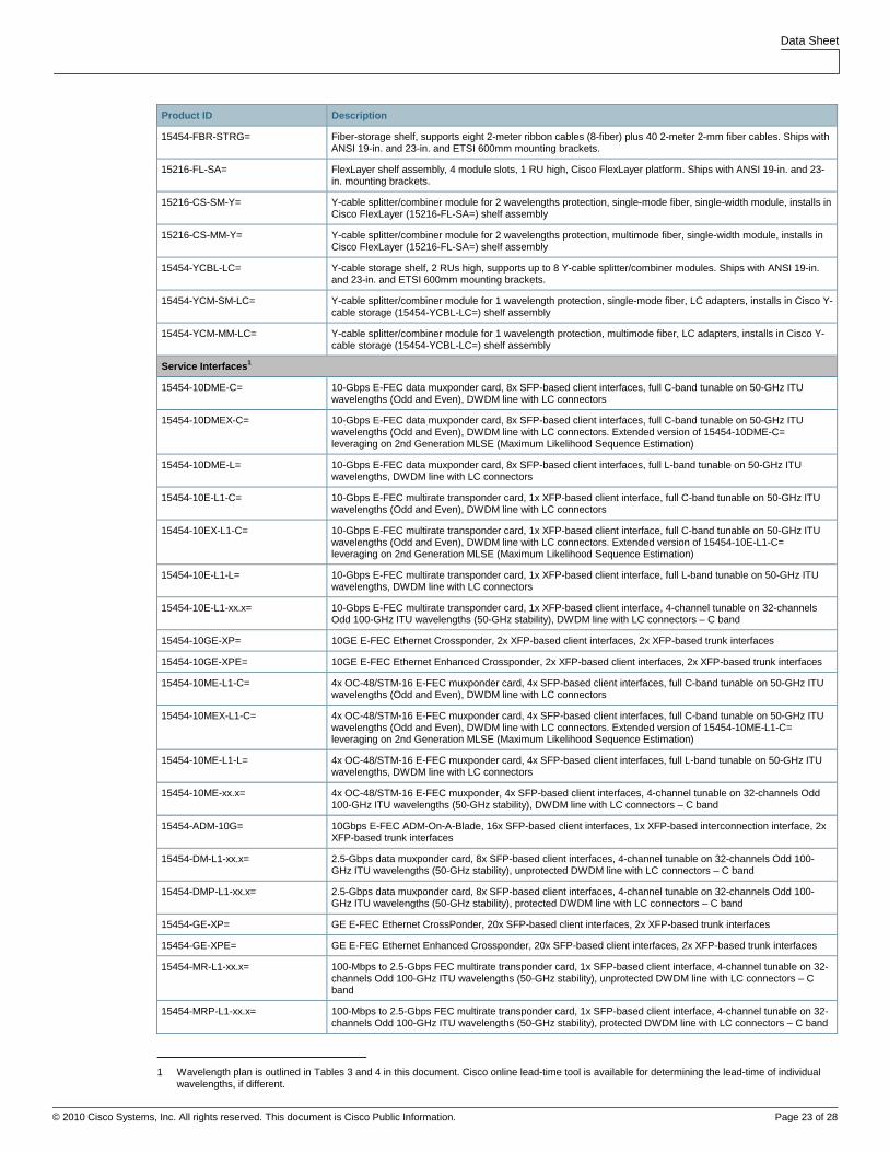
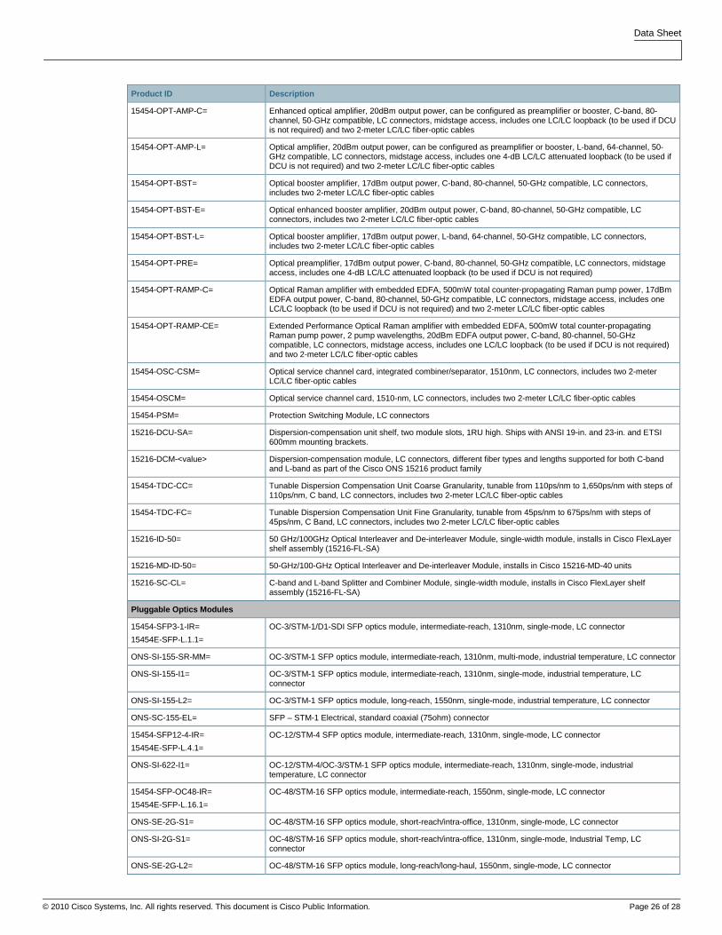
Table 8 provides ordering information.
Table 8. Ordering Information
Product ID Description
Common Equipment – M12
15454-SA-HD=
15454-SA-HD-DDR=
15454E-SA-ETSI=
Shelf assembly, Cisco ONS 15454
15454-TCC2P-K9=
15454E-TCC2P-K9=
15454-TCC3-K9=
15454E-TCC3-K9=
Timing, Communications, and Control Card, Version 2 Plus (TCC2P), 15454 chassis
Timing, Communications, and Control Card, Version 2 Plus (TCC2P), 15454E chassis
Timing, Communications, and Control Card, Version 3 (TCC3), I-Temp, 15454 chassis
Timing, Communications, and Control Card, Version 3 (TCC3), I-Temp, 15454E chassis
15454-CC-FTA=
15454E-CC-FTA=
15454-FTA3-T=
15454E-FTA-48V=
Controlled cooling fan-tray assembly, includes fan-tray filter
Fan-tray assembly, includes fan-tray filter
15454E-CTP-MIC48V= Mechanical interface card, craft, timing, and power inputs, ETSI
15454E-AP-MIC48V= Mechanical interface card, alarm, and power inputs, ETSI
15454-AIR-RAMP=
15454E-AIR-RAMP=
Air ramp (ships with ANSI 19-in. and 23-in. and ETSI 600mm mounting brackets)
15454-AIC-I=
15454E-AIC-I=
Alarm Interface Controller, international card
15454-BLANK=
15454E-BLANK=
15454E-BLANK-FMEC=
Shelf slot-filler panel, fits any slot in Cisco ONS 15454 ANSI shelf assembly
Shelf slot-filler panel, fits any slot in Cisco ONS 15454 ETSI shelf assembly
Shelf FMEC slot-filler panel, fits Cisco ONS 15454 ETSI shelf assembly
15454-MS-ISC-100T= Integrated 100T Ethernet switch for multi-shelf management

Data Sheet
© 2010 Cisco Systems, Inc. All rights reserved. This document is Cisco Public Information. Page 22 of 28
Product ID Description
15454-EAP-MF= Mechanical frame for Ethernet adapter panel (ships with ANSI 19-in. and 23-in. and ETSI 600mm mounting brackets). Ships with 2x RJ-45/RJ-45 cables (0.15m) to connect MS-ISC units with the TCC2P units and with 1x RJ-45/RJ-45 cable (0.5m) to connect the MS-ISC units among themselves.
15454-EAP= Ethernet adapter panel (to be used with MS-ISC-100T to allow proper cable management)
15454-MEC= Multiple Ethernet cable to replicate the MS-ISC-100T Ethernet ports on the EAP unit
Common Equipment – M6
15454-M6-SA= 6-service-slot MSTP shelf, includes M-SHIPKIT, M6-FTF
15454-M6-FTA= 6-service-slot MSTP chassis fan tray
15454-M6-LCD= 6-service-slot MSTP chassis LCD with backup memory
15454-M6-ECU= 6-service-slot MSTP chassis external cable connections
15454-M6-DC= 6-service-slot MSTP chassis DC power filter
15454-M6-AC= 6-service-slot MSTP chassis AC power supply
15454-M6-BRKT23= Right front inlet; left back exhaust
15454-M6-BRKT21= Inlet right front; exhaust left front, left back, or left top
15454-M6-BRKT19= No deflectors
15454-M6-PWRFLR= 6-service-slot MSTP power filter filler card
15454-M6-FTF= 6-service-slot MSTP chassis fan tray filter
15454-M6-DR= 6-service-slot MSTP chassis door
Common Equipment – M2
15454-M2-SA= 2-service-slot MSTP shelf, includes M-SHIPKIT, M2-FTF
15454-M2-FTA= 2-service-slot MSTP chassis fan tray
15454-M2-DC= 2-service-slot MSTP chassis DC ANSI filter with memory
15454-M2-DC-E= 2-service-slot MSTP chassis DC ETSI filter with memory
15454-M2-AC= 2-service-slot MSTP chassis AC power supply with memory
15454-M2-BRKT23= Right front inlet; left back exhaust
15454-M2-BRKT21= Inlet right front; exhaust left front, left back, or left top
15454-M2-BRKT19= No deflectors
15454-M2-WM= 2-service-slot MSTP chassis wall mount bracket
15454-M2-FTF= 2-service-slot MSTP chassis air filter
15454-M2-DR= 2-service-slot MSTP chassis door
Common Equipment – M6 and M2
15454-M-TNC-K9=
15454-M-TSC-K9=
Transport Node Controller for M2 and M6 chassis
Transport Shelf Controller for M2 and M6 chassis
15454-M-T-FILLER=
15454-M-FILLER=
Detectable control slot filler card
Detectable line slot filler card
Common Equipment
15454-PP-64-LC=
15454-PP2-64-LC=
15454-PP-80-LC=
64-port fiber patch-panel shelf, 1 rack unit (1RU) high, LC-to-LC connectors, 32 duplex LC adapters, supports up to 8 multi-fiber cable assemblies (1 MPO to 8x LC), includes 2 MPO to 8x LC 2.3-meter cable assemblies (uninstalled). Ships with ANSI 19-in. and 23-in. and ETSI 600mm mounting brackets.
64-port fiber patch-panel shelf, 2RU high, LC-to-LC connectors, 32 duplex LC adapters, includes 8 MPO to 8x LC 2.3-meter cable assemblies (pre-cabled). Ships with ANSI 19-in. and 23-in. and ETSI 600mm mounting brackets.
80-port fiber patch-panel shelf, 2RU high, LC-to-LC connectors, 40 duplex LC adapters, includes 10 MPO to 8x LC 2.3-meter cable assemblies (pre-cabled). Ships with ANSI 19-in. and 23-in. and ETSI 600mm mounting brackets.
15454-PP-MESH-4=
15454-PP-MESH-8=
Degree-4 mesh patch panel, 2RU high, 1x LC and 1x MPO adapter per direction. Ships with ANSI 19-in. and 23-in. and ETSI 600mm mounting brackets.
Degree-8 mesh patch panel, 2RU high, 1x LC and 1x MPO adapter per direction. Ships with ANSI 19-in. and 23-in. and ETSI 600mm mounting brackets.
15454-PP-4-SMR= Degree-4 mesh patch panel for single-mode ROADM, 1RU high, 1x MPO adapter per direction. Ships with ANSI 19-in. and 23-in. and ETSI 600mm mounting brackets.
Data Sheet
© 2010 Cisco Systems, Inc. All rights reserved. This document is Cisco Public Information. Page 23 of 28
Product ID Description
15454-FBR-STRG= Fiber-storage shelf, supports eight 2-meter ribbon cables (8-fiber) plus 40 2-meter 2-mm fiber cables. Ships with ANSI 19-in. and 23-in. and ETSI 600mm mounting brackets.
15216-FL-SA= FlexLayer shelf assembly, 4 module slots, 1 RU high, Cisco FlexLayer platform. Ships with ANSI 19-in. and 23-in. mounting brackets.
15216-CS-SM-Y= Y-cable splitter/combiner module for 2 wavelengths protection, single-mode fiber, single-width module, installs in Cisco FlexLayer (15216-FL-SA=) shelf assembly
15216-CS-MM-Y= Y-cable splitter/combiner module for 2 wavelengths protection, multimode fiber, single-width module, installs in Cisco FlexLayer (15216-FL-SA=) shelf assembly
15454-YCBL-LC= Y-cable storage shelf, 2 RUs high, supports up to 8 Y-cable splitter/combiner modules. Ships with ANSI 19-in. and 23-in. and ETSI 600mm mounting brackets.
15454-YCM-SM-LC= Y-cable splitter/combiner module for 1 wavelength protection, single-mode fiber, LC adapters, installs in Cisco Y-cable storage (15454-YCBL-LC=) shelf assembly
15454-YCM-MM-LC= Y-cable splitter/combiner module for 1 wavelength protection, multimode fiber, LC adapters, installs in Cisco Y-cable storage (15454-YCBL-LC=) shelf assembly
Service Interfaces 1
15454-10DME-C= 10-Gbps E-FEC data muxponder card, 8x SFP-based client interfaces, full C-band tunable on 50-GHz ITU wavelengths (Odd and Even), DWDM line with LC connectors
15454-10DMEX-C= 10-Gbps E-FEC data muxponder card, 8x SFP-based client interfaces, full C-band tunable on 50-GHz ITU wavelengths (Odd and Even), DWDM line with LC connectors. Extended version of 15454-10DME-C= leveraging on 2nd Generation MLSE (Maximum Likelihood Sequence Estimation)
15454-10DME-L= 10-Gbps E-FEC data muxponder card, 8x SFP-based client interfaces, full L-band tunable on 50-GHz ITU wavelengths, DWDM line with LC connectors
15454-10E-L1-C= 10-Gbps E-FEC multirate transponder card, 1x XFP-based client interface, full C-band tunable on 50-GHz ITU wavelengths (Odd and Even), DWDM line with LC connectors
15454-10EX-L1-C= 10-Gbps E-FEC multirate transponder card, 1x XFP-based client interface, full C-band tunable on 50-GHz ITU wavelengths (Odd and Even), DWDM line with LC connectors. Extended version of 15454-10E-L1-C= leveraging on 2nd Generation MLSE (Maximum Likelihood Sequence Estimation)
15454-10E-L1-L= 10-Gbps E-FEC multirate transponder card, 1x XFP-based client interface, full L-band tunable on 50-GHz ITU wavelengths, DWDM line with LC connectors
15454-10E-L1-xx.x= 10-Gbps E-FEC multirate transponder card, 1x XFP-based client interface, 4-channel tunable on 32-channels Odd 100-GHz ITU wavelengths (50-GHz stability), DWDM line with LC connectors – C band
15454-10GE-XP= 10GE E-FEC Ethernet Crossponder, 2x XFP-based client interfaces, 2x XFP-based trunk interfaces
15454-10GE-XPE= 10GE E-FEC Ethernet Enhanced Crossponder, 2x XFP-based client interfaces, 2x XFP-based trunk interfaces
15454-10ME-L1-C= 4x OC-48/STM-16 E-FEC muxponder card, 4x SFP-based client interfaces, full C-band tunable on 50-GHz ITU wavelengths (Odd and Even), DWDM line with LC connectors
15454-10MEX-L1-C= 4x OC-48/STM-16 E-FEC muxponder card, 4x SFP-based client interfaces, full C-band tunable on 50-GHz ITU wavelengths (Odd and Even), DWDM line with LC connectors. Extended version of 15454-10ME-L1-C= leveraging on 2nd Generation MLSE (Maximum Likelihood Sequence Estimation)
15454-10ME-L1-L= 4x OC-48/STM-16 E-FEC muxponder card, 4x SFP-based client interfaces, full L-band tunable on 50-GHz ITU wavelengths, DWDM line with LC connectors
15454-10ME-xx.x= 4x OC-48/STM-16 E-FEC muxponder, 4x SFP-based client interfaces, 4-channel tunable on 32-channels Odd 100-GHz ITU wavelengths (50-GHz stability), DWDM line with LC connectors – C band
15454-ADM-10G= 10Gbps E-FEC ADM-On-A-Blade, 16x SFP-based client interfaces, 1x XFP-based interconnection interface, 2x XFP-based trunk interfaces
15454-DM-L1-xx.x= 2.5-Gbps data muxponder card, 8x SFP-based client interfaces, 4-channel tunable on 32-channels Odd 100-GHz ITU wavelengths (50-GHz stability), unprotected DWDM line with LC connectors – C band
15454-DMP-L1-xx.x= 2.5-Gbps data muxponder card, 8x SFP-based client interfaces, 4-channel tunable on 32-channels Odd 100-GHz ITU wavelengths (50-GHz stability), protected DWDM line with LC connectors – C band
15454-GE-XP= GE E-FEC Ethernet CrossPonder, 20x SFP-based client interfaces, 2x XFP-based trunk interfaces
15454-GE-XPE= GE E-FEC Ethernet Enhanced Crossponder, 20x SFP-based client interfaces, 2x XFP-based trunk interfaces
15454-MR-L1-xx.x= 100-Mbps to 2.5-Gbps FEC multirate transponder card, 1x SFP-based client interface, 4-channel tunable on 32-channels Odd 100-GHz ITU wavelengths (50-GHz stability), unprotected DWDM line with LC connectors – C band
15454-MRP-L1-xx.x= 100-Mbps to 2.5-Gbps FEC multirate transponder card, 1x SFP-based client interface, 4-channel tunable on 32-channels Odd 100-GHz ITU wavelengths (50-GHz stability), protected DWDM line with LC connectors – C band
1 Wavelength plan is outlined in Tables 3 and 4 in this document. Cisco online lead-time tool is available for determining the lead-time of individual
wavelengths, if different.

Data Sheet
© 2010 Cisco Systems, Inc. All rights reserved. This document is Cisco Public Information. Page 24 of 28
Product ID Description
15454-OTU2-XP= 4x OTN E-FEC Multirate Xponder, 2x XFP-based trunk/client FEC interfaces, 2x XFP-based trunk/client E-FEC interfaces
15454-40G-MXP-C= 4x 10-Gbps DPSK 40-Gbps muxponder card, 4x XFP-based client interfaces, full C-band tunable on 50-GHz ITU wavelengths (Odd and Even), DWDM line with LC connectors
Optical Transmission Elements
15454-32-DMX= 32-channel demultiplexer 100-GHz (for use with 32-WSS), C-band, MPO connectors for drop path, LC connector for interconnection, includes one 2-meter LC/LC fiber-optic cables
15454-32-DMX-L= 32-channel demultiplexer 100-GHz (for use with 32-WSS), L-band, MPO connectors for drop path, LC connector for interconnection, includes one 2-meter LC/LC fiber-optic cables
15454-32DMX-O= 32-channel demultiplexer card, C-band, Odd grid, 100-GHz, MPO connectors for drop path, LC connector for interconnection, includes one 2-meter LC/LC fiber-optic cables
15454-32MUX-O= 32-channel multiplexer card, C-band, Odd grid, 100-GHz, MPO connectors for add path, LC connector for interconnection
15454-32-WSS= 32-channel wavelength selective switch 100-GHz, C-band, MPO connectors for add path, LC connectors for interconnection, includes two 2-meter LC/LC fiber-optic cables
15454-32-WSS-L= 32-channel wavelength selective switch 100-GHz, L-band, MPO connectors for add path, LC connectors for interconnection, includes two 2-meter LC/LC fiber-optic cables
15454-40-DMX-C= 40-channel demultiplexer 100-GHz (for use with 40-WSS-C, 40-MUX-C or 40-WXC-C), C-band, Odd grid, MPO connectors for drop path, LC connector for interconnection, includes one 2-meter LC/LC fiber-optic cables
15454-40-DMX-CE= 40-channel demultiplexer 100-GHz (for use with 40-WSS-CE), C-band, Even grid, MPO connectors for drop path, LC connector for interconnection, includes one 2-meter LC/LC fiber-optic cables
15454-40-MUX-C= 40-channel multiplexer 100-GHz (for use with 40-DMX-C or 40-WXC-C), C-band, Odd grid, MPO connectors for add path, LC connector for interconnection, includes one 2-meter LC/LC fiber-optic cables
15454-40-WSS-C= 40-channel wavelength selective switch 100GHz, C-band, Odd grid, MPO connectors for add path, LC connectors for interconnection, includes two 2-meter LC/LC fiber-optic cables
15454-40-WSS-CE= 40-channel wavelength selective switch 100-GHz, C-band, Even grid, MPO connectors for add path, LC connectors for interconnection, includes two 2-meter LC/LC fiber-optic cables
15454-40-WXC-C= 40-channel wavelength cross connect 100-GHz, C-band, Odd grid, MPO connector for interconnection with Mesh Patch Panel, LC connectors for interconnection, includes one 2-meter LC/LC fiber-optic cable
15454-80-WXC-C= 80-channel wavelength cross connect 50-GHz, C-band, Odd and Even grid, LC connectors
15454-40-SMR1-C= 40-channel single-module ROADM, 100-GHz, C-band, LC connectors for interconnection and add path, includes one 2-meter LC/LC fiber-optic cable and one 0-dB LC/LC loopback (to be used if DCU is not required). Combines the OSC add/drop filter, a pre-amplifier and a 2x1 WSS-based ROADM core into a single slot unit.
15454-40-SMR2-C= 40-channel single-module ROADM, 100-GHz, C-band, LC connectors for interconnection, MPO connector for interconnection with Mesh Patch Panel, includes one 0-dB LC/LC loopback (to be used if DCU is not required). Combines the OSC add/drop filter, PRE and BST amplifiers and a 4x1 WSS-based ROADM core.
15216-MD-40-ODD= 40-Channel Multiplexer and Demultiplexer Passive Patch Panel, 100-GHz, C-band – Odd, 2RU high, 40 duplex LC add and drop ports, 3 duplex LC ports for internal and monitor connections, USB port for passive inventory. Ships with ANSI 19-in. and 23-in. and ETSI 600mm mounting brackets.
15216-MD-40-EVEN= 40-Channel Multiplexer and Demultiplexer Passive Patch Panel, 100-GHz, C-band – Even, 2RU high, 40 duplex LC add and drop ports, 3 duplex LC ports for internal and monitor connections, USB port for passive inventory. Ships with ANSI 19-in. and 23-in. and ETSI 600mm mounting brackets.
15454-4MD-xx.x= 4-channel multiplexer and demultiplexer card, C-band, 100-GHz, LC connectors, includes two 2-meter LC/LC fiber-optic cables
15454-AD-1B-xx= 1-band OADM, C-band, 100-GHz, LC connectors, includes two 2-meter LC/LC fiber-optic cables
15454-AD-1C-xx.x= 1-channel OADM, C-band, 100-GHz, LC connectors, includes two 2-meter LC/LC fiber-optic cables
15454-AD-2C-xx.x= 2-channel OADM, C-band, 100-GHz, LC connectors, includes two 2-meter LC/LC fiber-optic cables
15454-AD-4B-xx= 4-band OADM, C-band, 100-GHz, LC connectors, includes two 2-meter LC/LC fiber-optic cables
15454-AD-4C-xx.x= 4-channel OADM, C-band, 100-GHz, LC connectors, includes two 2-meter LC/LC fiber-optic cables
15216-HD-EXT-PNL= Edge Mounting Bracket
15216-FLD-4-xx.x= Edge 4-Channel Bidirectional OADM Module 15xx.xx to 15xx.xx
15216-FLC-CWDM-8= Edge 8-Channel CWDM Multiplexer/Demultiplexer Module
15216-FLD-OSC= Edge Optical Service Channel Add/Drop
15454-MMU= Multi-ring/mesh upgrade unit, C-band and L-band (for use with 32-WSS/32-DMX or 32-WSS-L/32-DMX-L), LC connectors, includes two 2-meter LC/LC fiber-optic cables
15454-OPT-AMP-17C= Optical amplifier, 17dBm output power, 17dB gain, can be configured as preamplifier or booster, C-band, 80-

Data Sheet
© 2010 Cisco Systems, Inc. All rights reserved. This document is Cisco Public Information. Page 25 of 28
Product ID Description
channel, 50-GHz compatible, LC connectors, includes two 2-meter LC/LC fiber-optic cables
Data Sheet
© 2010 Cisco Systems, Inc. All rights reserved. This document is Cisco Public Information. Page 26 of 28
Product ID Description
15454-OPT-AMP-C= Enhanced optical amplifier, 20dBm output power, can be configured as preamplifier or booster, C-band, 80-channel, 50-GHz compatible, LC connectors, midstage access, includes one LC/LC loopback (to be used if DCU is not required) and two 2-meter LC/LC fiber-optic cables
15454-OPT-AMP-L= Optical amplifier, 20dBm output power, can be configured as preamplifier or booster, L-band, 64-channel, 50-GHz compatible, LC connectors, midstage access, includes one 4-dB LC/LC attenuated loopback (to be used if DCU is not required) and two 2-meter LC/LC fiber-optic cables
15454-OPT-BST= Optical booster amplifier, 17dBm output power, C-band, 80-channel, 50-GHz compatible, LC connectors, includes two 2-meter LC/LC fiber-optic cables
15454-OPT-BST-E= Optical enhanced booster amplifier, 20dBm output power, C-band, 80-channel, 50-GHz compatible, LC connectors, includes two 2-meter LC/LC fiber-optic cables
15454-OPT-BST-L= Optical booster amplifier, 17dBm output power, L-band, 64-channel, 50-GHz compatible, LC connectors, includes two 2-meter LC/LC fiber-optic cables
15454-OPT-PRE= Optical preamplifier, 17dBm output power, C-band, 80-channel, 50-GHz compatible, LC connectors, midstage access, includes one 4-dB LC/LC attenuated loopback (to be used if DCU is not required)
15454-OPT-RAMP-C= Optical Raman amplifier with embedded EDFA, 500mW total counter-propagating Raman pump power, 17dBm EDFA output power, C-band, 80-channel, 50-GHz compatible, LC connectors, midstage access, includes one LC/LC loopback (to be used if DCU is not required) and two 2-meter LC/LC fiber-optic cables
15454-OPT-RAMP-CE= Extended Performance Optical Raman amplifier with embedded EDFA, 500mW total counter-propagating Raman pump power, 2 pump wavelengths, 20dBm EDFA output power, C-band, 80-channel, 50-GHz compatible, LC connectors, midstage access, includes one LC/LC loopback (to be used if DCU is not required) and two 2-meter LC/LC fiber-optic cables
15454-OSC-CSM= Optical service channel card, integrated combiner/separator, 1510nm, LC connectors, includes two 2-meter LC/LC fiber-optic cables
15454-OSCM= Optical service channel card, 1510-nm, LC connectors, includes two 2-meter LC/LC fiber-optic cables
15454-PSM= Protection Switching Module, LC connectors
15216-DCU-SA= Dispersion-compensation unit shelf, two module slots, 1RU high. Ships with ANSI 19-in. and 23-in. and ETSI 600mm mounting brackets.
15216-DCM-<value> Dispersion-compensation module, LC connectors, different fiber types and lengths supported for both C-band and L-band as part of the Cisco ONS 15216 product family
15454-TDC-CC= Tunable Dispersion Compensation Unit Coarse Granularity, tunable from 110ps/nm to 1,650ps/nm with steps of 110ps/nm, C band, LC connectors, includes two 2-meter LC/LC fiber-optic cables
15454-TDC-FC= Tunable Dispersion Compensation Unit Fine Granularity, tunable from 45ps/nm to 675ps/nm with steps of 45ps/nm, C Band, LC connectors, includes two 2-meter LC/LC fiber-optic cables
15216-ID-50= 50 GHz/100GHz Optical Interleaver and De-interleaver Module, single-width module, installs in Cisco FlexLayer shelf assembly (15216-FL-SA)
15216-MD-ID-50= 50-GHz/100-GHz Optical Interleaver and De-interleaver Module, installs in Cisco 15216-MD-40 units
15216-SC-CL= C-band and L-band Splitter and Combiner Module, single-width module, installs in Cisco FlexLayer shelf assembly (15216-FL-SA)
Pluggable Optics Modules
15454-SFP3-1-IR=
15454E-SFP-L.1.1=
OC-3/STM-1/D1-SDI SFP optics module, intermediate-reach, 1310nm, single-mode, LC connector
ONS-SI-155-SR-MM= OC-3/STM-1 SFP optics module, intermediate-reach, 1310nm, multi-mode, industrial temperature, LC connector
ONS-SI-155-I1= OC-3/STM-1 SFP optics module, intermediate-reach, 1310nm, single-mode, industrial temperature, LC connector
ONS-SI-155-L2= OC-3/STM-1 SFP optics module, long-reach, 1550nm, single-mode, industrial temperature, LC connector
ONS-SC-155-EL= SFP – STM-1 Electrical, standard coaxial (75ohm) connector
15454-SFP12-4-IR=
15454E-SFP-L.4.1=
OC-12/STM-4 SFP optics module, intermediate-reach, 1310nm, single-mode, LC connector
ONS-SI-622-I1= OC-12/STM-4/OC-3/STM-1 SFP optics module, intermediate-reach, 1310nm, single-mode, industrial temperature, LC connector
15454-SFP-OC48-IR=
15454E-SFP-L.16.1=
OC-48/STM-16 SFP optics module, intermediate-reach, 1550nm, single-mode, LC connector
ONS-SE-2G-S1= OC-48/STM-16 SFP optics module, short-reach/intra-office, 1310nm, single-mode, LC connector
ONS-SI-2G-S1= OC-48/STM-16 SFP optics module, short-reach/intra-office, 1310nm, single-mode, Industrial Temp, LC connector
ONS-SE-2G-L2= OC-48/STM-16 SFP optics module, long-reach/long-haul, 1550nm, single-mode, LC connector

Data Sheet
© 2010 Cisco Systems, Inc. All rights reserved. This document is Cisco Public Information. Page 27 of 28
Product ID Description
ONS-SI-2G-L2= OC-48/STM-16 SFP optics module, long-reach/long-haul, 1550nm, single-mode, Industrial Temp, LC connector
ONS-SE-Z1= OC-48/STM-16/OC-12/STM-4/OC-3/STM-1 SFP optics module, 1310nm, single-mode, LC connector
ONS-SC-Z3-XXXX= OC-48/STM-16/GE SFP optics module, CWDM, XXXX-nm, single-mode, Commercial Temp, LC connector
ONS-SE-200-MM= ESCON SFP optics module, short-reach, 1310-nm, multimode, LC connector
ONS-SE-G2F-LX= GE, Fibre Channel (1- and 2-Gbps) and HDTV SFP optics module, long-reach, 1310nm, single-mode, LC connector
ONS-SE-G2F-SX= GE and Fibre Channel (1- and 2-Gbps) SFP optics module, short-reach, 850nm, multimode, LC connector
ONS-SE-GE-ZX= GE SFP optics module, 1000BASE-ZX interface, 1550nm, single-mode, LC connector
ONS-SI-GE-ZX= GE SFP optics module, 1000BASE-ZX interface, 1550nm, single-mode, Industrial Temp, LC connector
ONS-SE-ZE-EL= 10/100/1000 Ethernet SFP electrical module, BASE-T interface, RJ-45 connector
ONS-SE-4G-SM= 4-Gbps Fibre Channel SFP optics module, 1310nm, single-mode, LC connector
ONS-SE-GE-BXU= GE SFP optics module, 1000BASE BX U, single fiber application – upstream, Extended Temp, 1310nm TX and 1490nm RX, single-mode, single LC connector
ONS-SE-GE-BXD= GE SFP optics module, 1000BASE BX D, single fiber application – downstream, Extended Temp, 1490nm TX and 1310nm RX,single-mode, single LC connector
ONS-SE-4G-MM= 4-Gbps Fibre Channel SFP optics module, 850nm, multimode, LC connector
ONS-SC-4G-xx.x= 4-Gbps Fibre Channel SFP optics module, DWDM, 15xx.x, 100 GHz, LC connector - Commercial Temp
ONS-SC-2G-xx.x= OC-48/STM-16 SFP optics module, DWDM, 15xx.x-nm, single mode, LC connector
ONS-XC-10G-SR-MM= 10 GE/10-Gbps Fibre Channel XFP optics module, short-reach, 850nm, multimode, LC connector
ONS-XC-10G-S1= OC-192/STM-64/10 GE/10-Gbps Fibre Channel XFP optics module, short-reach, 1310nm, single-mode, LC connector
ONS-XC-10G-L2= OC-192/STM-64 XFP optics module, long-reach, 1550nm, single-mode, LC connector
ONS-XC-10G-I2= OC-192/STM-64 IR2/10 GE XFP optics module, intermediate-reach, 1550nm, single-mode, LC connector
ONS-XC-10G-xx.x= OC-192/STM-64/10 GE XFP optics module, DWDM, 15xx.x-nm, single-mode, LC connector
ONS-XC-10G-C= OC-192/STM-64/10 GE XFP optics module, DWDM, Full C-band Tunable, 50 GHz, single-mode, LC connector
ONS-XC-10G-xxxx= OC-192/10GE/OTU2, CWDM, xxxx mn, XFP Commercial Temp, 40km range
ONS-SC-E3-T3-PW= SFP-E3/DS-3 PDH over FE pseudowire – Commercial Temp
ONS-XC-8G-SM= 8-Gbps Fibre Channel XFP SM
ONS-SC-OSC-ULH= SFP-OC3/STM1/FE Optical Service Channel SFPs ULH–Commercial Temp
Cable Assemblies
15454-MPO-MPO-2= Multi-fiber patchcord – MPO 8-fiber ribbon to MPO 8-fiber ribbon, single mode, 2.0 meters (m)
15454-MPO-XMPO-2= Multi-fiber patchcord – MPO 8-fiber ribbon to MPO 8-fiber ribbon crossed, single mode, 2.0m, for use with SMR-2 units for Degree-2 ROADM Node configurations (no PP-4-SMR required)
15454-MPO-MPO-4= Multi-fiber patchcord – MPO 8-fiber ribbon to MPO 8-fiber ribbon, single mode, 4.0m
15454-MPO-MPO-6= Multi-fiber patchcord – MPO 8-fiber ribbon to MPO 8-fiber ribbon, single mode, 6.0m
15454-MPO-MPO-8= Multi-fiber patchcord – MPO 8-fiber ribbon to MPO 8-fiber ribbon, single mode, 8.0m
15454-MPO-8LC-2= Cable assembly, MPO 8-fiber ribbon to 8x LC/PC, single-mode, 2.3m
15454-LC-LC-2= Cable assembly, LC/PC-to-LC/PC, single-mode, 2.0m, 2mm jacket
15216-LC-LC-5= Cable assembly, LC/PC-to-LC/PC, single-mode, 4.0m, 2mm jacket
15216-LC-LC-10= Cable assembly, LC/PC-to-LC/PC, single-mode, 6.0m, 2mm jacket
15216-LC-LC-20= Cable assembly, LC/PC-to-LC/PC, single-mode, 8.0m, 2mm jacket
15216-LC-LC-MM-2= Cable assembly, LC/PC-to-LC/PC, multimode, 2.0m, 2mm jacket
15216-LC-LC-MM-5= Cable assembly, LC/PC-to-LC/PC, multimode, 5.0m, 2mm jacket
15216-LC-SC-5= Cable assembly, LC/PC-to-SC/UPC, single-mode, 4.0m, 2mm jacket
15216-LC-SC-10= Cable assembly, LC/PC-to-SC/UPC, single-mode, 6.0m, 2mm jacket
15216-LC-SC-20= Cable assembly, LC/PC-to-SC/UPC, single-mode, 8.0m, 2mm jacket
15454-MPO-8LC-4= Multi-fiber patchcord – MPO to 8xLC – 4m

Data Sheet
© 2010 Cisco Systems, Inc. All rights reserved. This document is Cisco Public Information. Page 28 of 28
Product ID Description
15454-MPO-8LC-6= Multi-fiber patchcord – MPO to 8xLC – 6m
15454-MPO-8LC-8= Multi-fiber patchcord – MPO to 8xLC – 8m
Software and User Documentation
15454-LIC-9.2.0K9
15454E-LIC-9.2.0K9
Right-to-use upgrade license, Release 9.2.0, Cisco ONS 15454
15454-R9.2.0SWK9=
15454E-R9.2.0SWK9=
System software, Release 9.2.0, Cisco ONS 15454, CD-ROM
SF15454M-R9.2.0K9
SF15454-R9.2.0K9
15454 ANSI MSTP Rel. 9.2.0 software, preloaded on TCC2P, TCC3, TNC, and TSC
15454 ANSI MSPP Rel. 9.2.0 software, preloaded on TCC2P and TCC3
SF15454ME-R9.2.0K9
SF15454E-R9.2.0K9
15454 ETSI MSTP Rel. 9.2.0 software, preloaded on TCC2P, TCC3, TNC, and TSC
15454 ETSI MSPP Rel. 9.2.0 software, preloaded on TCC2P and TCC3
15454-DOC9.2.0CD=
15454E-DOC9.2.0CD=
User document, Cisco ONS 15454, Release 9.2.0, Cisco ONS 15454, CD version
Warranty
The following are warranty terms that apply to Cisco ONS 15454 MSTP as well as services you may use during the
warranty period. Your formal Warranty Statement appears in the Cisco Information Packet that accompanies your
Cisco product.
● Hardware warranty duration: Five (5) years
● Software warranty duration: One (1) year
● Hardware replacement, repair, or refund procedure: Cisco or its service center will use commercially
reasonable efforts to ship a replacement part for delivery within fifteen (15) working days after receipt of the
defective product at Cisco's site. Actual delivery times of replacement products may vary depending on
customer location.
Product warranty terms and other information applicable to Cisco products are available at:
http://www.cisco.com/go/warranty.
Service and Support
Cisco offers a wide range of services programs to accelerate customer success. These innovative services
programs are delivered through a unique combination of people, processes, tools, and partners, resulting in high
levels of customer satisfaction. Cisco services help you to protect your network investment, optimize network
operations, and prepare your network for new applications to extend network intelligence and the power of your
business.
For more information about Cisco Services, refer to Cisco Technical Support Services or Cisco Advanced Services.
For More Information
For more information about the Cisco ONS 15454 Multiservice Transport Platform, contact your local account
representative or visit Cisco at: www.cisco.com/go/optical or www.cisco.com/go/IPoDWDM.

Data Sheet
© 2010 Cisco Systems, Inc. All rights reserved. This document is Cisco Public Information. Page 29 of 28
Printed in USA C78-601197-00 04/10