cisco ons 15454 sonet/sdh ml-series multilayer ethernet card … · contents vi cisco ons 15454...
TRANSCRIPT
Cisco ONS 15454 SONET/SDHML-Series Multilayer Ethernet CardSoftware Feature and Configuration GuideCisco IOS Release 12.1(20)EOProduct and Documentation Release 4.6Last updated: August 22, 2007
Corporate HeadquartersCisco Systems, Inc.170 West Tasman DriveSan Jose, CA 95134-1706 USAhttp://www.cisco.comTel: 408 526-4000
800 553-NETS (6387)Fax: 408 526-4100
Customer Order Number: DOC-7815992=Text Part Number: 78-15992-01

THE SPECIFICATIONS AND INFORMATION REGARDING THE PRODUCTS IN THIS MANUAL ARE SUBJECT TO CHANGE WITHOUT NOTICE. ALL STATEMENTS, INFORMATION, AND RECOMMENDATIONS IN THIS MANUAL ARE BELIEVED TO BE ACCURATE BUT ARE PRESENTED WITHOUT WARRANTY OF ANY KIND, EXPRESS OR IMPLIED. USERS MUST TAKE FULL RESPONSIBILITY FOR THEIR APPLICATION OF ANY PRODUCTS.
THE SOFTWARE LICENSE AND LIMITED WARRANTY FOR THE ACCOMPANYING PRODUCT ARE SET FORTH IN THE INFORMATION PACKET THAT SHIPPED WITH THE PRODUCT AND ARE INCORPORATED HEREIN BY THIS REFERENCE. IF YOU ARE UNABLE TO LOCATE THE SOFTWARE LICENSE OR LIMITED WARRANTY, CONTACT YOUR CISCO REPRESENTATIVE FOR A COPY.
The following information is for FCC compliance of Class A devices: This equipment has been tested and found to comply with the limits for a Class A digital device, pursuant to part 15 of the FCC rules. These limits are designed to provide reasonable protection against harmful interference when the equipment is operated in a commercial environment. This equipment generates, uses, and can radiate radio-frequency energy and, if not installed and used in accordance with the instruction manual, may cause harmful interference to radio communications. Operation of this equipment in a residential area is likely to cause harmful interference, in which case users will be required to correct the interference at their own expense.
The following information is for FCC compliance of Class B devices: The equipment described in this manual generates and may radiate radio-frequency energy. If it is not installed in accordance with Cisco’s installation instructions, it may cause interference with radio and television reception. This equipment has been tested and found to comply with the limits for a Class B digital device in accordance with the specifications in part 15 of the FCC rules. These specifications are designed to provide reasonable protection against such interference in a residential installation. However, there is no guarantee that interference will not occur in a particular installation.
Modifying the equipment without Cisco’s written authorization may result in the equipment no longer complying with FCC requirements for Class A or Class B digital devices. In that event, your right to use the equipment may be limited by FCC regulations, and you may be required to correct any interference to radio or television communications at your own expense.
You can determine whether your equipment is causing interference by turning it off. If the interference stops, it was probably caused by the Cisco equipment or one of its peripheral devices. If the equipment causes interference to radio or television reception, try to correct the interference by using one or more of the following measures:
• Turn the television or radio antenna until the interference stops.
• Move the equipment to one side or the other of the television or radio.
• Move the equipment farther away from the television or radio.
• Plug the equipment into an outlet that is on a different circuit from the television or radio. (That is, make certain the equipment and the television or radio are on circuits controlled by different circuit breakers or fuses.)
Modifications to this product not authorized by Cisco Systems, Inc. could void the FCC approval and negate your authority to operate the product.
The Cisco implementation of TCP header compression is an adaptation of a program developed by the University of California, Berkeley (UCB) as part of UCB’s public domain version of the UNIX operating system. All rights reserved. Copyright © 1981, Regents of the University of California.
NOTWITHSTANDING ANY OTHER WARRANTY HEREIN, ALL DOCUMENT FILES AND SOFTWARE OF THESE SUPPLIERS ARE PROVIDED “AS IS” WITH ALL FAULTS. CISCO AND THE ABOVE-NAMED SUPPLIERS DISCLAIM ALL WARRANTIES, EXPRESSED OR IMPLIED, INCLUDING, WITHOUT LIMITATION, THOSE OF MERCHANTABILITY, FITNESS FOR A PARTICULAR PURPOSE AND NONINFRINGEMENT OR ARISING FROM A COURSE OF DEALING, USAGE, OR TRADE PRACTICE.
IN NO EVENT SHALL CISCO OR ITS SUPPLIERS BE LIABLE FOR ANY INDIRECT, SPECIAL, CONSEQUENTIAL, OR INCIDENTAL DAMAGES, INCLUDING, WITHOUT LIMITATION, LOST PROFITS OR LOSS OR DAMAGE TO DATA ARISING OUT OF THE USE OR INABILITY TO USE THIS MANUAL, EVEN IF CISCO OR ITS SUPPLIERS HAVE BEEN ADVISED OF THE POSSIBILITY OF SUCH DAMAGES.
Cisco ONS 15454 SONET/SDH ML-Series Multilayer Ethernet Card Software Feature and Configuration GuideCopyright © 2007 Cisco Systems, Inc. All rights reserved.
CCVP, the Cisco logo, and Welcome to the Human Network are trademarks of Cisco Systems, Inc.; Changing the Way We Work, Live, Play, and Learn is a service mark of Cisco Systems, Inc.; and Access Registrar, Aironet, BPX, Catalyst, CCDA, CCDP, CCIE, CCIP, CCNA, CCNP, CCSP, Cisco, the Cisco Certified Internetwork Expert logo, Cisco IOS, Cisco Press, Cisco Systems, Cisco Systems Capital, the Cisco Systems logo, Cisco Unity, Enterprise/Solver, EtherChannel, EtherFast, EtherSwitch, Fast Step, Follow Me Browsing, FormShare, GigaDrive, HomeLink, Internet Quotient, IOS, iPhone, IP/TV, iQ Expertise, the iQ logo, iQ Net Readiness Scorecard, iQuick Study, LightStream, Linksys, MeetingPlace, MGX, Networkers, Networking Academy, Network Registrar, PIX, ProConnect, ScriptShare, SMARTnet, StackWise, The Fastest Way to Increase Your Internet Quotient, and TransPath are registered trademarks of Cisco Systems, Inc. and/or its affiliates in the United States and certain other countries.
All other trademarks mentioned in this document or Website are the property of their respective owners. The use of the word partner does not imply a partnership relationship between Cisco and any other company. (0710R)
Cisco ONS 15454 SONET/SDH ML-Series Multilayer EtherneJanuary 2004
C O N T E N T S
About the Cisco IOS Documentation xvii
Revision History xviii
Document Objectives xviii
Audience xviii
Document Organization xix
Related Documentation xx
Document Conventions xxi
Where to Find Safety and Warning Information xxii
Obtaining Documentation xxii
Cisco.com xxii
Ordering Documentation xxii
Cisco Optical Networking Product Documentation CD-ROM xxii
Documentation Feedback xxiii
Obtaining Technical Assistance xxiii
Cisco TAC Website xxiii
Opening a TAC Case xxiii
TAC Case Priority Definitions xxiv
Obtaining Additional Publications and Information xxiv
C H A P T E R 1 Overview 1-1
ML-Series Card Description 1-1
ML-Series Feature List 1-2
Key ML-Series Features 1-4
Cisco IOS 1-4
DRPRI 1-5
EoMPLS 1-5
Link Aggregation (FEC, GEC, and POS) 1-5
POS Ports 1-5
RPR 1-6
RMON 1-6
SNMP 1-6
SONET/SDH Alarms 1-6
SONET/SDH Port Encapsulation (HDLC, PPP/BCP, and LEX) 1-7
iiit Card Software Feature and Configuration Guide, R4.6
Contents
SW-LCAS 1-7
TL1 1-8
VCAT 1-8
VRF Lite 1-9
Ethernet Clocking Versus SONET/SDH Clocking 1-9
C H A P T E R 2 CTC Operations 2-1
Displaying ML-Series Ethernet Statistics on CTC 2-1
Displaying ML-Series POS Statistics on CTC 2-3
Displaying ML-Series Ethernet Ports Provisioning Information on CTC 2-5
Displaying ML-Series POS Ports Provisioning Information on CTC 2-7
Managing SONET/SDH Alarms 2-8
Displaying Maintenance Information 2-9
Provisioning SONET/SDH Circuits 2-9
Provisioning VCAT Circuits 2-9
J1 Path Trace 2-10
C H A P T E R 3 Initial Configuration 3-1
Hardware Installation 3-1
Cisco IOS on the ML-Series Card 3-1
Opening a Cisco IOS Session Using CTC 3-2
Telnetting to the Node IP Address and Slot Number 3-2
Telnetting to a Management Port 3-4
ML-Series IOS CLI Console Port 3-4
RJ-11 to RJ-45 Console Cable Adapter 3-4
Connecting a PC or Terminal to the Console Port 3-5
Startup Configuration File 3-6
Manually Creating a Startup Configuration File Through the Serial Console Port 3-7
Passwords 3-7
Configuring the Management Port 3-8
Configuring the Hostname 3-9
Loading a Cisco IOS Startup Configuration File Through CTC 3-9
Multiple Microcode Images 3-11
Changing the Working Microcode Image 3-11
Cisco IOS Command Modes 3-13
Using the Command Modes 3-14
Exit 3-14
Getting Help 3-15
ivCisco ONS 15454 SONET/SDH ML-Series Multilayer Ethernet Card Software Feature and Configuration Guide, R4.6
January 2004
Contents
C H A P T E R 4 Configuring Interfaces 4-1
Interface Configuration 4-1
MAC Addresses 4-2
Interface Port ID 4-2
Instructions for Configuring Interfaces 4-3
Understanding Interfaces 4-4
Configuring the Fast Ethernet Interfaces (ML100T-12) 4-4
Configuring the Gigabit Ethernet Interface (ML1000-2) 4-5
Monitoring Operations on the Fast Ethernet and Gigabit Ethernet Interfaces 4-6
POS on the ML-Series Card 4-8
ML-Series SONET/SDH Transmission Rates 4-8
SONET Frame Fundamentals 4-8
C2 Byte 4-9
C2 Byte and Scrambling 4-10
Third-Party POS Interfaces 4-12
Configuring the ML-Series POS Interfaces 4-12
Monitoring Operations on the POS Interface and POS Controller 4-13
Additional Configurations 4-14
Setting the MTU Size 4-14
Configuring Framing 4-15
Configuring POS SPE Scrambling 4-15
SONET/SDH Alarms 4-15
Configuring SONET/SDH Alarms 4-16
Common ML-Series POS Configurations 4-17
ML-Series Card to ML-Series Card 4-17
ML-Series Card to Cisco 12000 GSR-Series Router 4-18
ML-Series Card to G-Series Card 4-20
C H A P T E R 5 Configuring Bridging 5-1
Understanding Bridging 5-1
Configuring Bridging 5-2
Monitoring and Verifying Bridging 5-3
C H A P T E R 6 Configuring STP and RSTP 6-1
STP Features 6-1
STP Overview 6-2
Supported STP Instances 6-2
Bridge Protocol Data Units 6-2
vCisco ONS 15454 SONET/SDH ML-Series Multilayer Ethernet Card Software Feature and Configuration Guide, R4.6
January 2004
Contents
Election of the Root Switch 6-3
Bridge ID, Switch Priority, and Extended System ID 6-4
Spanning-Tree Timers 6-4
Creating the Spanning-Tree Topology 6-4
Spanning-Tree Interface States 6-5
Blocking State 6-6
Listening State 6-7
Learning State 6-7
Forwarding State 6-7
Disabled State 6-7
Spanning-Tree Address Management 6-8
STP and IEEE 802.1Q Trunks 6-8
Spanning Tree and Redundant Connectivity 6-8
Accelerated Aging to Retain Connectivity 6-9
RSTP 6-9
Supported RSTP Instances 6-9
Port Roles and the Active Topology 6-10
Rapid Convergence 6-11
Synchronization of Port Roles 6-12
Bridge Protocol Data Unit Format and Processing 6-13
Processing Superior BPDU Information 6-14
Processing Inferior BPDU Information 6-14
Topology Changes 6-14
Interoperability with IEEE 802.1D STP 6-15
Configuring STP and RSTP Features 6-15
Default STP and RSTP Configuration 6-16
Disabling STP and RSTP 6-16
Configuring the Root Switch 6-17
Configuring the Port Priority 6-17
Configuring the Path Cost 6-18
Configuring the Switch Priority of a Bridge Group 6-19
Configuring the Hello Time 6-19
Configuring the Forwarding-Delay Time for a Bridge Group 6-20
Configuring the Maximum-Aging Time for a Bridge Group 6-20
Verifying and Monitoring STP and RSTP Status 6-20
C H A P T E R 7 Configuring VLANs 7-1
Understanding VLANs 7-1
Configuring IEEE 802.1Q VLAN Encapsulation 7-2
viCisco ONS 15454 SONET/SDH ML-Series Multilayer Ethernet Card Software Feature and Configuration Guide, R4.6
January 2004
Contents
IEEE 802.1Q VLAN Configuration 7-3
Monitoring and Verifying VLAN Operation 7-5
C H A P T E R 8 Configuring IEEE 802.1Q and Layer 2 Protocol Tunneling 8-1
Understanding IEEE 802.1Q Tunneling 8-1
Configuring IEEE 802.1Q Tunneling 8-4
IEEE 802.1Q Tunneling and Compatibility with Other Features 8-4
Configuring an IEEE 802.1Q Tunneling Port 8-4
IEEE 802.1Q Example 8-5
Understanding VLAN-Transparent and VLAN-Specific Services 8-7
VLAN-Transparent and VLAN-Specific Services Configuration Example 8-7
Understanding Layer 2 Protocol Tunneling 8-10
Configuring Layer 2 Protocol Tunneling 8-10
Default Layer 2 Protocol Tunneling Configuration 8-11
Layer 2 Protocol Tunneling Configuration Guidelines 8-11
Configuring Layer 2 Tunneling on a Port 8-12
Configuring Layer 2 Tunneling Per-VLAN 8-13
Monitoring and Verifying Tunneling Status 8-13
C H A P T E R 9 Configuring Link Aggregation 9-1
Understanding Link Aggregation 9-1
Configuring EtherChannel 9-2
EtherChannel Configuration Example 9-3
Configuring POS Channel 9-4
POS Channel Configuration Example 9-5
Understanding Encapsulation over EtherChannel or POS Channel 9-7
Configuring Encapsulation over EtherChannel or POS Channel 9-7
Encapsulation over EtherChannel Example 9-7
Monitoring and Verifying EtherChannel and POS 9-9
C H A P T E R 10 Configuring Networking Protocols 10-1
Basic IP Routing Protocol Configuration 10-1
RIP 10-2
EIGRP 10-2
OSPF 10-3
BGP 10-3
Enabling IP Routing 10-4
Configuring IP Routing 10-4
viiCisco ONS 15454 SONET/SDH ML-Series Multilayer Ethernet Card Software Feature and Configuration Guide, R4.6
January 2004
Contents
Configuring RIP 10-5
RIP Authentication 10-8
Summary Addresses and Split Horizon 10-8
Configuring OSPF 10-9
OSPF Interface Parameters 10-13
OSPF Area Parameters 10-14
Other OSPF Behavior Parameters 10-16
Change LSA Group Pacing 10-18
Loopback Interface 10-19
Monitoring OSPF 10-19
Configuring EIGRP 10-20
EIGRP Router Mode Commands 10-22
EIGRP Interface Mode Commands 10-23
Configure EIGRP Route Authentication 10-24
Monitoring and Maintaining EIGRP 10-25
Border Gateway Protocol and Classless Interdomain Routing 10-27
Configuring BGP 10-27
Verifying the BGP Configuration 10-28
Configuring IS-IS 10-29
Verifying the IS-IS Configuration 10-30
Configuring Static Routes 10-31
Monitoring Static Routes 10-32
Monitoring and Maintaining the IP Network 10-33
Understanding IP Multicast Routing 10-33
Configuring IP Multicast Routing 10-34
Monitoring and Verifying IP Multicast Operation 10-35
C H A P T E R 11 Configuring IRB 11-1
Integrated Routing and Bridging 11-1
Configuring IRB 11-2
Configuring IRB Example 11-3
Configuring Router A 11-3
Configuring Router B 11-4
Monitoring and Verifying IRB 11-4
11-6
C H A P T E R 12 Configuring VRF Lite 12-1
Understanding VRF Lite 12-1
Configuring VRF Lite 12-2
viiiCisco ONS 15454 SONET/SDH ML-Series Multilayer Ethernet Card Software Feature and Configuration Guide, R4.6
January 2004

Contents
VRF Lite Configuration Example 12-2
Monitoring and Verifying VRF Lite 12-7
C H A P T E R 13 Configuring Quality of Service 13-1
Understanding QoS 13-1
Priority Mechanism in IP and Ethernet 13-2
IP Precedence and Differentiated Services Code Point 13-2
Ethernet CoS 13-3
ML-Series QoS 13-3
Classification 13-4
Policing 13-4
Marking and Discarding 13-5
Queuing 13-6
Scheduling 13-6
Multicast QoS 13-7
Control Packets and L2 Tunneled Protocols 13-8
Priority Marking 13-8
QinQ Implementation 13-9
Flow Control Pause and QoS 13-9
QoS on RPR 13-10
Configuring QoS 13-10
Creating a Traffic Class 13-11
Creating a Traffic Policy 13-12
Attaching a Traffic Policy to an Interface 13-15
Configuring CoS-based QoS 13-16
Monitoring and Verifying QoS Configuration 13-16
QoS Configuration Examples 13-17
Traffic Classes Defined Example 13-18
Traffic Policy Created Example 13-18
class-map match-any and class-map match-all Commands Example 13-19
match spr1 Interface Example 13-19
ML-Series VoIP Example 13-20
ML-Series Policing Example 13-20
ML-Series CoS-based QoS Example 13-21
Understanding CoS-based Packet Statistics 13-22
Configuring CoS-based Packet Statistics 13-23
ixCisco ONS 15454 SONET/SDH ML-Series Multilayer Ethernet Card Software Feature and Configuration Guide, R4.6
January 2004
Contents
C H A P T E R 14 Configuring the Switching Database Manager 14-1
Understanding the SDM 14-1
SDM Regions 14-1
Configuring SDM 14-2
Configuring SDM Regions 14-2
Configuring Access Control List Size in TCAM 14-3
C H A P T E R 15 Configuring Access Control Lists 15-1
Understanding ACLs 15-1
ML-Series ACL Support 15-1
IP ACLs 15-2
Named IP ACLs 15-2
User Guidelines 15-2
Creating IP ACLs 15-3
Creating Numbered Standard and Extended IP ACLs 15-3
Creating Named Standard IP ACLs 15-4
Creating Named Extended IP ACLs (Control Plane Only) 15-4
Applying the ACL to an Interface 15-4
Modifying ACL TCAM Size 15-5
C H A P T E R 16 Configuring Resilient Packet Ring 16-1
Understanding RPR 16-1
Packet Handling Operations 16-2
Ring Wrapping 16-3
MAC Address and VLAN Support 16-4
Configuring Point-to-Point Circuits on CTC for RPR 16-4
Configuring RPR on Cisco IOS 16-5
RPR Cisco IOS Configuration Example 16-8
Monitoring and Verifying RPR 16-10
Understanding Dual RPR Interconnect 16-10
Configuring DRPRI 16-12
DRPRI IOS Configuration Example 16-13
Monitoring and Verifying DRPRI 16-17
C H A P T E R 17 Configuring Ethernet over MPLS 17-1
Understanding EoMPLS 17-1
EoMPLS Support 17-3
EoMPLS Restrictions 17-3
xCisco ONS 15454 SONET/SDH ML-Series Multilayer Ethernet Card Software Feature and Configuration Guide, R4.6
January 2004

Contents
EoMPLS Quality of Service 17-4
Configuring EoMPLS 17-4
EoMPLS Configuration Guidelines 17-5
VC Type 4 Configuration on PE-CLE Port 17-5
VC Type 5 Configuration on PE-CLE Port 17-6
EoMPLS Configuration on PE-CLE SPR Interface 17-7
Bridge Group Configuration on MPLS Cloud-facing Port 17-7
Setting the Priority of Packets with the EXP 17-8
EoMPLS Configuration Example 17-9
Monitoring and Verifying EoMPLS 17-11
A P P E N D I X A Command Reference A-1
A P P E N D I X B Unsupported CLI Commands B-1
Unsupported Privileged Exec Commands B-1
Unsupported Global Configuration Commands B-1
Unsupported POS Interface Configuration Commands B-3
Unsupported FastEthernet or GigabitEthernet Interface Configuration Commands B-4
Unsupported Port-Channel Interface Configuration Commands B-5
Unsupported BVI Interface Configuration Commands B-5
A P P E N D I X C Using Technical Support C-1
Gathering Information About Your Internetwork C-1
Getting the Data from Your ML-Series Card C-2
Providing Data to Your Technical Support Representative C-3
xiCisco ONS 15454 SONET/SDH ML-Series Multilayer Ethernet Card Software Feature and Configuration Guide, R4.6
January 2004

Contents
xiiCisco ONS 15454 SONET/SDH ML-Series Multilayer Ethernet Card Software Feature and Configuration Guide, R4.6
January 2004
F I G U R E S
Figure 2-1 Displaying ML-Series Ethernet Statistics 2-2
Figure 2-2 Displaying ML-Series POS Statistics 2-4
Figure 2-3 Displaying ML-Series Ethernet Port Provisioning Information 2-6
Figure 2-4 Displaying POS Port Provisioning Information 2-7
Figure 2-5 Managing ML-Series SONET/SDH Alarms 2-8
Figure 2-6 Displaying Maintenance Information 2-9
Figure 3-1 CTC IOS Window 3-2
Figure 3-2 CTC Node View Showing IP Address and Slot Number 3-3
Figure 3-3 Console Cable Adapter 3-4
Figure 3-4 Connecting to the Console Port 3-6
Figure 4-1 Three SONET Layers 4-9
Figure 4-2 ML-Series Card to ML-Series Card POS Configuration 4-18
Figure 4-3 ML-Series Card to Cisco 12000 Series Gigabit Switch Router (GSR) POS Configuration 4-19
Figure 4-4 ML-Series Card to G-Series Card POS Configuration 4-20
Figure 5-1 Bridging Example 5-2
Figure 6-1 Spanning-Tree Topology 6-5
Figure 6-2 Spanning-Tree Interface States 6-6
Figure 6-3 Spanning Tree and Redundant Connectivity 6-8
Figure 6-4 Proposal and Agreement Handshaking for Rapid Convergence 6-12
Figure 6-5 Sequence of Events During Rapid Convergence 6-13
Figure 7-1 VLANs Spanning Devices in a Network 7-2
Figure 7-2 Bridging IEEE 802.1Q VLANs 7-4
Figure 8-1 IEEE 802.1Q Tunnel Ports in a Service-Provider Network 8-2
Figure 8-2 Normal, IEEE 802.1Q, and IEEE 802.1Q-Tunneled Ethernet Packet Formats 8-3
Figure 8-3 ERMS Example 8-8
Figure 9-1 Encapsulation over EtherChannel Example 9-3
Figure 9-2 POS Channel Example 9-6
Figure 9-3 Encapsulation over EtherChannel Example 9-8
Figure 10-1 IP Routing Protocol Example Using OSPF 10-11
Figure 11-1 IRB Example 11-3
Figure 12-1 VRF Lite—Sample Network Scenario 12-3
xiiiCisco ONS 15454 SONET/SDH ML-Series Multilayer Ethernet Card Software Feature and Configuration Guide, R4.6
January 2004

Figures
Figure 13-1 IP Precedence and DSCP 13-2
Figure 13-2 Ethernet Frame and the CoS Bit (IEEE 802.1p) 13-3
Figure 13-3 ML-Series QoS Flow 13-3
Figure 13-4 Dual Leaky Bucket Policer Model 13-5
Figure 13-5 Queuing and Scheduling Model 13-7
Figure 13-6 QinQ 13-9
Figure 13-7 ML-Series VoIP Example 13-20
Figure 13-8 ML-Series Policing Example 13-20
Figure 13-9 ML-Series CoS Example 13-21
Figure 16-1 RPR Packet Handling Operations 16-2
Figure 16-2 RPR Ring Wrapping 16-3
Figure 16-3 RPR Configuration Example 16-8
Figure 16-4 Dual RPR Interconnect Network and Paired Cards 16-11
Figure 17-1 EoMPLS Service Provider Network 17-2
Figure 17-2 EoMPLS Configuration Example 17-9
xivCisco ONS 15454 SONET/SDH ML-Series Multilayer Ethernet Card Software Feature and Configuration Guide, R4.6
January 2004
T A B L E S
Table 2-1 ML-Series Ethernet Statistics Fields and Buttons 2-2
Table 2-2 Ethernet Parameters 2-2
Table 2-3 ML-Series POS Statistics Fields and Buttons 2-4
Table 2-4 POS Parameters 2-4
Table 3-1 RJ-11 to RJ-45 Pin Mapping 3-4
Table 3-2 Microcode Image Feature Comparison 3-11
Table 3-3 Cisco IOS Command Modes 3-13
Table 4-1 Transmission Multiples Supported by ML-Series Cards 4-8
Table 4-2 C2 Byte Common Values 4-9
Table 4-3 Default MTU Size 4-15
Table 4-4 ML-Series Parameter Configuration for Connection to a Cisco 12000 GSR-Series Router 4-20
Table 6-1 Switch Priority Value and Extended System ID 6-4
Table 6-2 Spanning-Tree Timers 6-4
Table 6-3 Port State Comparison 6-10
Table 6-4 RSTP BPDU Flags 6-13
Table 6-5 Default STP and RSTP Configuration 6-16
Table 6-6 Commands for Displaying Spanning-Tree Status 6-20
Table 8-1 VLAN-Transparent Service Versus VLAN-Specific Services 8-7
Table 8-2 Default Layer 2 Protocol Tunneling Configuration 8-11
Table 8-3 Commands for Monitoring and Maintaining Tunneling 8-13
Table 10-1 Default RIP Configuration 10-5
Table 10-2 Default OSPF Configuration 10-10
Table 10-3 Show IP OSPF Statistics Commands 10-19
Table 10-4 Default EIGRP Configuration 10-21
Table 10-5 IP EIGRP Clear and Show Commands 10-26
Table 10-6 BGP Show Commands 10-28
Table 10-7 IS-IS Show Commands 10-30
Table 10-8 Routing Protocol Default Administrative Distances 10-32
Table 10-9 Commands to Clear IP Routes or Display Route Status 10-33
Table 10-10 IP Multicast Routing Show Commands 10-35
Table 11-1 Commands for Monitoring and Verifying IRB 11-5
xvCisco ONS 15454 SONET/SDH ML-Series Multilayer Ethernet Card Software Feature and Configuration Guide, R4.6
January 2004
Tables
Table 11-2 show interfaces irb Field Descriptions 11-6
Table 12-1 Commands for Monitoring and Verifying VRF Lite 12-7
Table 13-1 Commands for QoS Status 13-16
Table 13-2 Packet Statistics on ML-Series Card Interfaces 13-22
Table 13-3 Commands for CoS-based Packet Statistics 13-23
Table 14-1 Default Partitioning by Application Region in TCAM 14-2
Table 14-2 Partitioning the TCAM Size for ACLs 14-3
Table 15-1 Commands for Numbered Standard and Extended IP ACLs 15-3
Table 15-2 Applying ACL to Interface 15-5
Table 17-1 Applicable EoMPLS QoS Statements and Actions 17-4
Table 17-2 Commands for Monitoring and Maintaining Tunneling 17-12
Table A-1 Scrambling and c2 Default Values A-5
Table A-2 pos flag c2 Default Values A-5
xviCisco ONS 15454 SONET/SDH ML-Series Multilayer Ethernet Card Software Feature and Configuration Guide, R4.6
January 2004
About the Cisco IOS Documentation
Note The terms "Unidirectional Path Switched Ring" and "UPSR" may appear in Cisco literature. These terms do not refer to using Cisco ONS 15xxx products in a unidirectional path switched ring configuration. Rather, these terms, as well as "Path Protected Mesh Network" and "PPMN," refer generally to Cisco's path protection feature, which may be used in any topological network configuration. Cisco does not recommend using its path protection feature in any particular topological network configuration.
This section explains the objectives, intended audience, and organization of this publication and describes the conventions that convey instructions and other information.
This section provides the following information:
• Document Objectives
• Audience
• Document Organization
• Related Documentation
• Document Conventions
• Where to Find Safety and Warning Information
• Obtaining Documentation
• Documentation Feedback
• Obtaining Technical Assistance
• Obtaining Additional Publications and Information
xviiCisco ONS 15454 SONET/SDH ML-Series Multilayer Ethernet Card Software Feature and Configuration Guide, R4.6
January 2004
About the Cisco IOS DocumentationRevision History
Revision History
Document ObjectivesThis guide explains software features and configuration for Cisco IOS on the ML-Series card. The ML-Series card is a module in the Cisco ONS 15454 SONET/SDH system. Use this guide in conjunction with the appropriate publications listed in the Related Documentation section.
AudienceTo use this publication, you should be familiar with Cisco IOS and preferably have technical networking background and experience.
Date Notes
08/22/2007 Updated About this Guide
xviiiCisco ONS 15454 SONET/SDH ML-Series Multilayer Ethernet Card Software Feature and Configuration Guide, R4.6
January 2004
About the Cisco IOS DocumentationDocument Organization
Document OrganizationThis Cisco ONS 15454 SONET/SDH ML-Series Multilayer Ethernet Card Software Feature and Configuration Guide, R4.6 is organized into the following chapters:
• Chapter 1, “Overview,” provides a description of the ML-Series card, a feature list, and explanations of key features.
• Chapter 2, “CTC Operations,”provides details and procedures for using Cisco Transport Controller (CTC) software with the ML-Series card.
• Chapter 3, “Initial Configuration,” provides procedures to access the ML-Series card and create and manage startup configuration files.
• Chapter 4, “Configuring Interfaces,” provides information on the ML-Series card interfaces and procedures for the interfaces.
• Chapter 5, “Configuring Bridging,” provides bridging examples and procedures for the ML-Series card.
• Chapter 6, “Configuring STP and RSTP,” provides spanning tree and rapid spanning tree examples and procedures for the ML-Series card.
• Chapter 7, “Configuring VLANs,” provides VLAN examples and procedures for the ML-Series card.
• Chapter 8, “Configuring IEEE 802.1Q and Layer 2 Protocol Tunneling,” provides tunneling examples and procedures for the ML-Series card.
• Chapter 9, “Configuring Link Aggregation,” provides Etherchannel and packet-over-SONET/SDH (POS) channel examples and procedures for the ML-Series card.
• Chapter 10, “Configuring Networking Protocols,” provides network protocol examples and procedures for the ML-Series card.
• Chapter 11, “Configuring IRB,” provides integrated routing and bridging (IRB) examples and procedures for the ML-Series card.
• Chapter 12, “Configuring VRF Lite,” provides VPN Routing and Forwarding Lite (VRF Lite) examples and procedures for the ML-Series card.
• Chapter 13, “Configuring Quality of Service,” provides puality of service (QoS) examples and procedures for the ML-Series card.
• Chapter 14, “Configuring the Switching Database Manager,” provides switching database manager examples and procedures for the ML-Series card.
• Chapter 15, “Configuring Access Control Lists,” provides access control list (ACL) examples and procedures for the ML-Series card.
• Chapter 16, “Configuring Resilient Packet Ring,” provides resilient packet ring (RPR) examples and procedures for the ML-Series card.
• Chapter 17, “Configuring Ethernet over MPLS,” provides Ethernet over Multiprotocol Label Switching (EoMPLS) examples and procedures for the ML-Series card.
• Appendix A, “Command Reference,” is an alphabetical listing of unique ML-Series card Cisco IOS commands with definitions and examples.
• Appendix B, “Unsupported CLI Commands,” is a categorized and alphabetized listing of Cisco IOS commands that the ML-Series card does not support.
• Appendix C, “Using Technical Support,” instructs the user on using the Cisco Technical Assistance Center (Cisco TAC) for ML-Series card problems.
xixCisco ONS 15454 SONET/SDH ML-Series Multilayer Ethernet Card Software Feature and Configuration Guide, R4.6
January 2004
About the Cisco IOS DocumentationRelated Documentation
Related DocumentationUse this Cisco ONS 15454 SONET/SDH ML-Series Multilayer Ethernet Card Software Feature and Configuration Guide, R4.6 in conjunction with the following general ONS 15454 or ONS 15454 SDH system publications:
• To install, turn up, provision, and maintain a Cisco ONS 15454 node and network, refer to the Cisco ONS 15454 Procedure Guide.
• For alarm clearing, general troubleshooting, and hardware replacement procedures for a Cisco ONS 15454 node, refer to the Cisco ONS 15454 Troubleshooting Guide.
• For detailed reference information on a Cisco ONS 15454 node, refer to the Cisco ONS 15454 Reference Manual.
• To install, turn up, provision, and maintain a Cisco ONS 15454 SDH node and network, refer to the Cisco ONS 15454 SDH Procedure Guide.
• For alarm clearing, general troubleshooting, and hardware replacement procedures for the Cisco ONS 15454 SDH node, refer to the Cisco ONS 15454 SDH Troubleshooting Guide.
• For detailed reference information on the Cisco ONS 15454 SDH node, refer to the Cisco ONS 15454 SDH Reference Manual.
The ML-Series card employs the Cisco IOS Modular QoS CLI (MQC). For more information on general MQC configuration, refer to the following IOS documents:
• Cisco IOS Quality of Service Solutions Configuration Guide, Release 12.1 at this URL: http://www.cisco.com/univercd/cc/td/doc/product/software/ios121/121cgcr/qos_c/index.htm
• Cisco IOS Quality of Service Solutions Command Reference, Release 12.1 at this URL: http://www.cisco.com/univercd/cc/td/doc/product/software/ios121/121cgcr/qos_r/index.htm
The ML-Series card employs Cisco IOS 12.1. For more general information on Cisco IOS 12.1, refer to the extensive Cisco IOS documentation at:
• http://www.cisco.com/univercd/cc/td/doc/product/software/ios121.htm
• http://www.cisco.com/univercd/home/home.htm
xxCisco ONS 15454 SONET/SDH ML-Series Multilayer Ethernet Card Software Feature and Configuration Guide, R4.6
January 2004
About the Cisco IOS DocumentationDocument Conventions
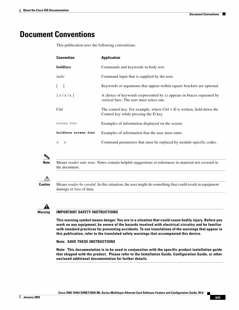
Document ConventionsThis publication uses the following conventions:
Note Means reader take note. Notes contain helpful suggestions or references to material not covered in the document.
Caution Means reader be careful. In this situation, the user might do something that could result in equipment damage or loss of data.
Convention Application
boldface Commands and keywords in body text.
italic Command input that is supplied by the user.
[ ] Keywords or arguments that appear within square brackets are optional.
{ x | x | x } A choice of keywords (represented by x) appears in braces separated by vertical bars. The user must select one.
Ctrl The control key. For example, where Ctrl + D is written, hold down the Control key while pressing the D key.
screen font Examples of information displayed on the screen.
boldface screen font Examples of information that the user must enter.
< > Command parameters that must be replaced by module-specific codes.
Warning IMPORTANT SAFETY INSTRUCTIONS
This warning symbol means danger. You are in a situation that could cause bodily injury. Before you work on any equipment, be aware of the hazards involved with electrical circuitry and be familiar with standard practices for preventing accidents. To see translations of the warnings that appear in this publication, refer to the translated safety warnings that accompanied this device.
Note: SAVE THESE INSTRUCTIONS
Note: This documentation is to be used in conjunction with the specific product installation guide that shipped with the product. Please refer to the Installation Guide, Configuration Guide, or other enclosed additional documentation for further details.
xxiCisco ONS 15454 SONET/SDH ML-Series Multilayer Ethernet Card Software Feature and Configuration Guide, R4.6
January 2004
About the Cisco IOS DocumentationWhere to Find Safety and Warning Information
Where to Find Safety and Warning InformationFor safety and warning information, refer to the Cisco Optical Products Safety and Compliance Information document that accompanied the product. This publication describes the international agency compliance and safety information for the Cisco ONS 15454 systems. It also includes translations of the safety warnings that appear in the ONS 15454 system documentation.
Obtaining DocumentationCisco documentation and additional literature are available on Cisco.com. Cisco also provides several ways to obtain technical assistance and other technical resources. These sections explain how to obtain technical information from Cisco Systems.
Cisco.comYou can access the most current Cisco documentation on the World Wide Web at this URL:
http://www.cisco.com/univercd/home/home.htm
You can access the Cisco website at this URL:
http://www.cisco.com
International Cisco websites can be accessed from this URL:
http://www.cisco.com/public/countries_languages.shtml
Ordering DocumentationYou can find instructions for ordering documentation at this URL:
http://www.cisco.com/univercd/cc/td/doc/es_inpck/pdi.htm
You can order Cisco documentation in these ways:
• Registered Cisco.com users (Cisco direct customers) can order Cisco product documentation from the Ordering tool:
http://www.cisco.com/en/US/partner/ordering/index.shtml
• Nonregistered Cisco.com users can order documentation through a local account representative by calling Cisco Systems Corporate Headquarters (California, USA) at 408 526-7208 or, elsewhere in North America, by calling 800 553-NETS (6387).
Cisco Optical Networking Product Documentation CD-ROMOptical networking-related documentation, including Cisco ONS 15454 and Cisco ONS 15454 SDH product documentation, is available in a CD-ROM package that ships with your product. The Optical Networking Product Documentation CD-ROM is updated periodically and may be more current than printed documentation.
xxiiCisco ONS 15454 SONET/SDH ML-Series Multilayer Ethernet Card Software Feature and Configuration Guide, R4.6
January 2004
About the Cisco IOS DocumentationDocumentation Feedback
Documentation FeedbackYou can submit e-mail comments about technical documentation to [email protected].
You can submit comments by using the response card (if present) behind the front cover of your document or by writing to the following address:
Cisco SystemsAttn: Customer Document Ordering170 West Tasman DriveSan Jose, CA 95134-9883
We appreciate your comments.
Obtaining Technical AssistanceFor all customers, partners, resellers, and distributors who hold valid Cisco service contracts, the Cisco Technical Assistance Center (TAC) provides 24-hour-a-day, award-winning technical support services, online and over the phone. Cisco.com features the Cisco TAC website as an online starting point for technical assistance. If you do not hold a valid Cisco service contract, please contact your reseller.
Cisco TAC WebsiteThe Cisco TAC website provides online documents and tools for troubleshooting and resolving technical issues with Cisco products and technologies. The Cisco TAC website is available 24 hours a day, 365 days a year. The Cisco TAC website is located at this URL:
http://www.cisco.com/tac
Accessing all the tools on the Cisco TAC website requires a Cisco.com user ID and password. If you have a valid service contract but do not have a login ID or password, register at this URL:
http://tools.cisco.com/RPF/register/register.do
Opening a TAC CaseUsing the online TAC Case Open Tool is the fastest way to open P3 and P4 cases. (P3 and P4 cases are those in which your network is minimally impaired or for which you require product information.) After you describe your situation, the TAC Case Open Tool automatically recommends resources for an immediate solution. If your issue is not resolved using the recommended resources, your case will be assigned to a Cisco TAC engineer. The online TAC Case Open Tool is located at this URL:
http://www.cisco.com/tac/caseopen
For P1 or P2 cases (P1 and P2 cases are those in which your production network is down or severely degraded) or if you do not have Internet access, contact Cisco TAC by telephone. Cisco TAC engineers are assigned immediately to P1 and P2 cases to help keep your business operations running smoothly.
To open a case by telephone, use one of the following numbers:
Asia-Pacific: +61 2 8446 7411 (Australia: 1 800 805 227) EMEA: +32 2 704 55 55 USA: 1 800 553-2447
xxiiiCisco ONS 15454 SONET/SDH ML-Series Multilayer Ethernet Card Software Feature and Configuration Guide, R4.6
January 2004
About the Cisco IOS DocumentationTAC Case Priority Definitions
For a complete listing of Cisco TAC contacts, go to this URL:
http://www.cisco.com/warp/public/687/Directory/DirTAC.shtml
TAC Case Priority DefinitionsTo ensure that all cases are reported in a standard format, Cisco has established case priority definitions.
Priority 1 (P1)—Your network is “down” or there is a critical impact to your business operations. You and Cisco will commit all necessary resources around the clock to resolve the situation.
Priority 2 (P2)—Operation of an existing network is severely degraded, or significant aspects of your business operation are negatively affected by inadequate performance of Cisco products. You and Cisco will commit full-time resources during normal business hours to resolve the situation.
Priority 3 (P3)—Operational performance of your network is impaired, but most business operations remain functional. You and Cisco will commit resources during normal business hours to restore service to satisfactory levels.
Priority 4 (P4)—You require information or assistance with Cisco product capabilities, installation, or configuration. There is little or no effect on your business operations.
Obtaining Additional Publications and InformationInformation about Cisco products, technologies, and network solutions is available from various online and printed sources.
• Cisco Marketplace provides a variety of Cisco books, reference guides, and logo merchandise. Go to this URL to visit the company store:
http://www.cisco.com/go/marketplace/
• The Cisco Product Catalog describes the networking products offered by Cisco Systems, as well as ordering and customer support services. Access the Cisco Product Catalog at this URL:
http://cisco.com/univercd/cc/td/doc/pcat/
• Cisco Press publishes a wide range of general networking, training and certification titles. Both new and experienced users will benefit from these publications. For current Cisco Press titles and other information, go to Cisco Press online at this URL:
http://www.ciscopress.com
• Packet magazine is the Cisco quarterly publication that provides the latest networking trends, technology breakthroughs, and Cisco products and solutions to help industry professionals get the most from their networking investment. Included are networking deployment and troubleshooting tips, configuration examples, customer case studies, tutorials and training, certification information, and links to numerous in-depth online resources. You can access Packet magazine at this URL:
http://www.cisco.com/packet
• iQ Magazine is the Cisco bimonthly publication that delivers the latest information about Internet business strategies for executives. You can access iQ Magazine at this URL:
http://www.cisco.com/go/iqmagazine
xxivCisco ONS 15454 SONET/SDH ML-Series Multilayer Ethernet Card Software Feature and Configuration Guide, R4.6
January 2004

About the Cisco IOS DocumentationObtaining Additional Publications and Information
• Internet Protocol Journal is a quarterly journal published by Cisco Systems for engineering professionals involved in designing, developing, and operating public and private internets and intranets. You can access the Internet Protocol Journal at this URL:
http://www.cisco.com/ipj
• Training—Cisco offers world-class networking training. Current offerings in network training are listed at this URL:
http://www.cisco.com/en/US/learning/index.html
xxvCisco ONS 15454 SONET/SDH ML-Series Multilayer Ethernet Card Software Feature and Configuration Guide, R4.6
January 2004

About the Cisco IOS DocumentationObtaining Additional Publications and Information
xxviCisco ONS 15454 SONET/SDH ML-Series Multilayer Ethernet Card Software Feature and Configuration Guide, R4.6
January 2004
Cisco ONS 15454 SONET/SDH ML-Series Multilayer Ethernet Card SoftwarJuly 2005
C H A P T E R 1
OverviewThis chapter provides an overview of the ML1000-2 and ML100T-12 cards for the ONS 15454 (SONET) and ONS 15454 SDH. It lists Ethernet and SONET/SDH capabilities and Cisco IOS and Cisco Transport Controller (CTC) software features, with brief descriptions of selected features.
This chapter contains the following major sections:
• ML-Series Card Description, page 1-1
• ML-Series Feature List, page 1-2
• Key ML-Series Features, page 1-4
ML-Series Card DescriptionThe ML-Series cards are independent Gigabit Ethernet (ML1000-2) or Fast Ethernet (ML100T-12) Layer 3 switches that process up to 5.7 Mpps. The cards are integrated into the ONS 15454 SONET or the ONS 15454 SDH. An ONS 15454 SONET with a 10-Gigabit Cross-Connect card (XC10G) can host the card in any traffic card slot, but an ONS 15454 SONET with a Cross-Connect card (XC) or Cross Connect Virtual Tributary card (XCVT) can only host the ML-Series card in the four traffic slots. An ONS 15454 SDH can host the card in any traffic card slot with any cross-connect card.
The card ships loaded with Cisco IOS Release 12.1(20)EO, and the Cisco IOS command-line interface (CLI) is the primary user interface for the ML-Series card. Most configuration for the card, such as Ethernet port, bridging, and VLAN, can be done only via the Cisco IOS CLI.
But Cisco Transport Controller (CTC), the ONS 15454 SONET/SDH graphical user interface (GUI), also supports the ML-Series card. SONET/SDH circuits cannot be provisioned through Cisco IOS, but must be configured through CTC (or TL1 on the ONS 15454 SONET). CTC offers ML-Series card status information, SONET/SDH alarm management, Cisco IOS Telnet session initialization, Cisco IOS configuration file management, provisioning, inventory, and other standard functions.
The ML100T-12 features 12 RJ-45 interfaces, and the ML1000-2 features two Small Form Factor Pluggable (SFP) slots supporting short wavelength (SX) and long wavelength (LX) optical modules. The ML100T-12 and the ML1000-2 use the same hardware and software base and offer the same feature sets. For detailed card specifications, refer to the “Ethernet Cards” chapter of the Cisco ONS 15454 Reference Manual or the Cisco ONS 15454 SDH Reference Manual.
The card features two virtual Packet over SONET/SDH (POS) ports, which function in a manner similar to OC-N card ports. The SONET/SDH circuits are provisioned through CTC in the same manner as standard OC-N card circuits. The ML-Series POS ports supports virtual concatenation (VCAT) of SONET/SDH circuits and a software link capacity adjustment scheme (SW-LCAS).
1-1e Feature and Configuration Guide, R4.6
Chapter 1 OverviewML-Series Feature List
ML-Series Feature ListThis section lists the features of the ML100T-12 and the ML1000-2 cards.
• Layer 1 data features
– 10/100BASE-TX half-duplex and full-duplex data transmission
– 1000BASE-SX, 1000BASE-LX full-duplex data transmission
• SONET/SDH features
– Two POS virtual ports
– LEX, Cisco high-level data link control (HDLC) or point-to-point protocol/bridging control protocol (PPP/BCP) encapsulation for POS
– VCAT with SW-LCAS
– PPP
– G-Series card compatible (with LEX encapsulation only)
• Layer 2 bridging features
– Transparent bridging
– MAC address learning, aging, and switching by hardware
– Protocol tunneling
– Multiple Spanning Tree (MST) protocol tunneling
– 255 active bridge group maximum
– 60,000 MAC address maximum per card and 8,000 MAC address maximum per bridge group
– Integrated routing and bridging (IRB)
– IEEE 802.1P/Q-based VLAN trunking
– IEEE 802.1Q VLAN tunneling
– IEEE 802.1D Spanning Tree Protocol (STP) and IEEE 802.1W Rapid Spanning Tree Protocol (RSTP)
– IEEE 802.1D STP instance per bridge group
– Resilient packet ring (RPR)
– Dual RPR Interconnect (DRPRI)
– Ethernet over Multiprotocol Label Switching (EoMPLS)
– VLAN-transparent and VLAN-specific services (Ethernet Relay Multipoint Service (ERMS))
• Fast EtherChannel (FEC) features (ML100T-12)
– Bundling of up to four Fast Ethernet ports
– Load sharing based on source and destination IP addresses of unicast packets
– Load sharing for bridge traffic based on MAC addresses
– IRB
– IEEE 802.1Q trunking
– Up to 6 active FEC port channels
• Gigabit EtherChannel (GEC) features (ML1000-2)
1-2Cisco ONS 15454 SONET/SDH ML-Series Multilayer Ethernet Card Software Feature and Configuration Guide, R4.6
July 2005
Chapter 1 OverviewML-Series Feature List
– Bundling the two Gigabit Ethernet ports
– Load sharing for bridge traffic based on MAC addresses
– IRB
– IEEE 802.1Q trunking
• POS channel
– Bundling the two POS ports
– LEX encapsulation only
– IRB
– IEEE 802.1Q trunking
• Layer 3 routing, switching, and forwarding
– Default routes
– IP unicast and multicast forwarding
– Simple IP access control lists (ACLs) (both Layer 2 and Layer 3 forwarding path)
– Extended IP ACLs in software (control-plane only)
– IP and IP multicast routing and switching between Ethernet ports
– Reverse Path Forwarding (RPF) multicast (not RPF unicast)
– Load balancing among equal cost paths based on source and destination IP addresses
– Up to 18,000 IP routes
– Up to 20,000 IP host entries
– Up to 40 IP multicast groups
– IRB routing mode support
• Supported routing protocols
– Virtual Private Network (VPN) Routing and Forwarding Lite (VRF Lite)
– Intermediate System-to-Intermediate System (IS-IS) Protocol
– Routing Information Protocol (RIP and RIP II)
– Enhanced Interior Gateway Routing Protocol (EIGRP)
– Open Shortest Path First (OSPF) Protocol
– Protocol Independent Multicast (PIM)—Sparse, sparse-dense, and dense modes
– Secondary addressing
– Static routes
– Local proxy ARP
– Border Gateway Protocol (BGP)
– Classless interdomain routing (CIDR)
• Quality of service (QoS) features
– Service level agreements (SLAs) with 1-Mbps granularity
– Input policing
– Guaranteed bandwidth (weighted round-robin [WDRR] plus strict priority scheduling)
– Low latency queuing support for unicast Voice over IP (VoIP)
1-3Cisco ONS 15454 SONET/SDH ML-Series Multilayer Ethernet Card Software Feature and Configuration Guide, R4.6
July 2005

Chapter 1 OverviewKey ML-Series Features
– Class of service (CoS) based on Layer 2 priority, VLAN ID, Layer 3 Type of Service/DiffServ Code Point (TOS)/(DSCP), and port
– CoS-based packet statistics
• Additional protocols
– Cisco Discovery Protocol (CDP) support on Ethernet ports
– Dynamic Host Configuration Protocol (DHCP) relay
– Hot Standby Router Protocol (HSRP) over 10/100 Ethernet, Gigabit Ethernet, FEC, GEC, and Bridge Group Virtual Interface (BVI)
– Internet Control Message Protocol (ICMP)
• Management features
– Cisco IOS
– CTC
– Remote Network Monitoring (RMON)
– Simple Network Management Protocol (SNMP)
– Transaction Language 1 (TL1)
• System features
– NEBS3 compliant
– Multiple Microcode Images
• CTC features
– Standard STS/STM and VCAT circuit provisioning for POS virtual ports
– SONET/SDH alarm reporting for path alarms and other ML-Series card specific alarms
– Raw port statistics
– Standard inventory and card management functions
– J1 Path Trace
– Cisco IOS CLI Telnet sessions from CTC
– Cisco IOS startup configuration file management from CTC
Key ML-Series FeaturesThis section describes selected key features and their implementation on the ML-Series card.
Cisco IOSCisco IOS controls the data functions of the ML-Series card and comes preloaded on the ONS 15454 SONET/SDH Timing Communications and Control 2 Card (TCC2) card. Users cannot update the ML-Series Cisco IOS image in the same manner as the Cisco IOS system image on a Cisco Catalyst Series. An ML-Series Cisco IOS image upgrade is accomplished only through the ONS 15454 SONET/SDH CTC, and Cisco IOS images for the ML-Series card are available only as part of an
1-4Cisco ONS 15454 SONET/SDH ML-Series Multilayer Ethernet Card Software Feature and Configuration Guide, R4.6
July 2005

Chapter 1 OverviewDRPRI
ONS 15454 SONET or SDH software release. This Cisco IOS image is included on the standard ONS 15454 SONET/SDH System Software CD under the package file name M_I.bin and full file name ons15454m-i7-mz. The images are not available for download or shipped separately.
DRPRIThe bridge-group protocol DRPRI is an RPR mechanism that interconnects rings for protection from ONS node failure. The protocol provides two parallel connections of the rings linked by a special instance of RSTP. One connection is the active node and the other is the standby node. During a failure of the active node, link, or card, a proprietary algorithm detects the failure and causes a switchover to the standby node. DRPRI provides a less than 200-msec recovery time for Layer 2 bridged traffic when the ML-Series card uses the enhanced microcode image. The Layer 2 recovery time is up to 12 seconds for other microcode images. The recovery time for Layer 3 unicast and multicast traffic also depends on the convergence time of the routing protocol implemented regardless of the microcode image used.
EoMPLSEoMPLS provides a tunneling mechanism for Ethernet traffic through an MPLS-enabled Layer 3 core. It encapsulates Ethernet protocol data units (PDUs) inside MPLS packets and using label stacking forwards them across the MPLS network. EoMPLS is an Internet Engineering Task Force (IETF) standard-track protocol based on the Martini draft. EoMPLS allows service providers to offer customers a virtual Ethernet line service or VLAN service using the service provider's existing MPLS backbone.
Link Aggregation (FEC, GEC, and POS)The ML-Series offers Fast EtherChannel, Gigabit EtherChannel, and POS channel link aggregation. Link aggregation groups multiple ports into a larger logical port and provides resiliency during the failure of any individual ports. The ML-Series supports a maximum of four Ethernet ports in Fast EtherChannel, two Ethernet ports in Gigabit EtherChannel, and two SONET/SDH virtual ports in POS channel. POS channel is only supported with LEX encapsulation.
Traffic flows map to individual ports based on MAC source address (SA)/destination address (DA) for bridged packets and IP SA/DA for routed packets. There is no support for policing or class-based packet priorities when link aggregation is configured.
POS PortsOn the ONS 15454 SONET, ML-Series cards feature two SONET virtual ports with a maximum combined bandwidth of STS-48. Each port carries an STS circuit with a size of STS-1, STS-3c, STS-6c, STS-9c, STS-12c, or STS-24c. For step-by-step instructions on configuring an ML-Series card SONET STS circuit, refer to the “Create Circuits and VT Tunnels” chapter of the Cisco ONS 15454 Procedure Guide.
On the ONS 15454 SDH, ML-Series cards feature two SDH virtual ports with a maximum combined bandwidth of VC4-16c. Each port carries an STM circuit with a size of VC3, VC4, VC4-2C, VC4-3C, VC4-4C or VC4-8C. For step-by-step instructions on configuring an ML-Series card SDH STM circuit, refer to the “Create Circuits and Tunnels” chapter of the Cisco ONS 15454 SDH Procedure Guide.
1-5Cisco ONS 15454 SONET/SDH ML-Series Multilayer Ethernet Card Software Feature and Configuration Guide, R4.6
July 2005

Chapter 1 OverviewRPR
RPRRPR is an emerging network architecture designed for metro fiber ring networks. This new MAC protocol is designed to overcome the limitations of STP, RSTP, and SONET in packet-based networks. RPR convergence times are comparable to SONET and much faster than STP or RSTP. RPR operates at the Layer 2 level and is compatible with Ethernet and protected or unprotected SONET circuits.
RMON The ML-Series card features remote monitoring (RMON) that allows network operators to monitor the health of the network with a network management system (NMS). The ML-Series card Ethernet interfaces support RMON for statistics, utilization, and history.For general information about using Cisco IOS to manage RMON, refer to the “Configuring RMON Support” chapter of the Cisco IOS Configuration Fundamentals Configuration Guide.
The MIBs supported are:
• RFC-2819—RMON MIB
• RFC-2358—Ether-Like-MIB
• RFC-2233—IF MIB
SNMPBoth the ONS 15454 SONET/SDH and the ML-Series cards have SNMP agents and support SNMP Version 1 (SNMPv1) and SNMP Version 2c (SNMPv2c) sets and traps. The ONS 15454 SONET/SDH accepts, validates, and forwards get/getNext/set requests to the ML-Series through a proxy agent. The ML-Series requests contain the slot identification of the ML-Series card to distinguish the request from a general ONS 15454 SNMP request. Responses from the ML-Series are relayed by the ONS 15454 to the requesting SNMP agents.
The ML-Series card SNMP support includes:
• Spanning Tree Protocol (STP) traps from Bridge-MIB (RFC 1493)
• Authentication traps from RFC 1157
• Link-up and link-down traps for Ethernet ports from IF-MIB (RFC 1573)
• Export of QoS statistics through the CISCO-PORT-QOS-MIB extension
1 The ML-Series card CISCO-PORT-QOS-MIB extension includes support for COS-based QoS indexing. It does not support configuration objects.
For more information on how the ONS 15454 or ONS 15454 SDH implements SNMP, refer to the “SNMP” chapter of the Cisco ONS 15454 Reference Manual or the Cisco ONS 15454 SDH Reference Manual. For more information on specific MIBs, refer to the Cisco SNMP Object Navigator at http://www.cisco.com/pcgi-bin/Support/Mibbrowser/unity.pl.
SONET/SDH AlarmsOn the ONS 15454 SONET, the ML-Series card reports Telcordia GR-253 SONET alarms in the Alarms panel of CTC and in the Cisco IOS CLI. The card reports SONET Path alarms, including path alarm indication signal (AIS-P), path loss of pointer (LOP-P), path unequipped (UNEQ-P), path remote
1-6Cisco ONS 15454 SONET/SDH ML-Series Multilayer Ethernet Card Software Feature and Configuration Guide, R4.6
July 2005
Chapter 1 OverviewSONET/SDH Port Encapsulation (HDLC, PPP/BCP, and LEX)
fault indication (RFI-P), path trace identifier mismatch (TIM-P), path payload level mismatch (PLM-P), path payload defect indication (PDI-P), bit eror rate-signal failure (BER-SF-B3), and bit error rate-signal degrade (BER-SD-B3). It also reports other alarms, including BPU/COM Fail, Board Fail, port link-down, and no-config. The ML-Series also supports path trace, path, and raw port statistics on CTC. For more information on alarms and alarm definitions, refer to the “Alarm Troubleshooting” chapter of the Cisco ONS 15454 Troubleshooting Guide and the “Manage Alarms” chapter of the Cisco ONS 15454 Procedure Guide.
On the ONS 15454 SDH, the ML-Series card reports SDH alarms on the Alarms panel of CTC and other alarms, including BPU/COM Fail, Board Fail, port link-down, and no-config. The ML-Series also supports path trace, path, and raw port statistics on CTC. For more information on alarms, refer to the “Alarm Troubleshooting” chapter of the Cisco ONS 15454 SDH Troubleshooting Guide and the “Manage Alarms” chapter of the Cisco ONS 15454 SDH Procedure Guide.
SONET/SDH Port Encapsulation (HDLC, PPP/BCP, and LEX)The ML-Series supports three forms of SONET/SDH port encapsulation: Cisco HDLC, PPP/BCP, and LEX. Cisco HDLC is standard on most Cisco data devices. It does not offer VLAN trunking support. PPP/BCP is a popular standard linked to RFC 2878. It supports VLAN trunking via BCP. LEX is a protocol used by the G-Series cards. This protocol supports VLAN trunking and is based on PPP over HDLC.
The SONET/SDH port encapsulation allows the ML-Series to connect to the OC-N ports of switches and routers supporting POS, as well as the G-Series Ethernet cards on the ONS 15454 SONET, ONS 15454 SDH, and ONS 15327. All three formats support bridging and routing, standard SONET/SDH payload scrambling, and HDLC frame check sequence.
SW-LCASLCAS increases VCAT flexibility by allowing the dynamic reconfiguration of VCAT groups without interrupting the operation of non-involved members. SW-LCAS is the software implementation of a LCAS-type feature. SW-LCAS differs from LCAS because it is not errorless and uses a different handshaking mechanism. SW-LCAS on the ML-Series card allows the automatic addition or removal of a VCAT group member in the event of a failure or recovery on two-fiber BLSR. The protection mechanism software operates based on ML-Series card link events. SW-LCAS allows service providers to configure VCAT member circuits on the ML-Series as protection channel access (PCA). This PCA traffic is dropped in the event of a protection switch, but is suitable for excess or noncommited traffic and can double total available bandwidth on the circuit.
For step-by-step instructions on configuring SW-LCAS, refer to the “Create Circuits and VT Tunnels” chapter of the Cisco ONS 15454 Procedure Guide or the “Create Circuits and Tunnels” chapter of the Cisco ONS 15454 SDH Procedure Guide. For more general information on SW-LCAS, refer to the “Circuits and Tunnels” chapter of the Cisco ONS 15454 Reference Manual or the Cisco ONS 15454 SDH Reference Manual.
1-7Cisco ONS 15454 SONET/SDH ML-Series Multilayer Ethernet Card Software Feature and Configuration Guide, R4.6
July 2005

Chapter 1 OverviewTL1
TL1For the ONS 15454 SONET, the TL1 on the ML-Series card can be used for card inventory, fault or alarm management, card provisioning, and retrieval of status information for both data and SONET ports. TL1 can also be used to provision SONET STS circuits and transfer a Cisco IOS startup configuration file to the TCC2 card memory. For specific TL1 commands and general TL1 information, refer to the Cisco ONS 15454 and Cisco ONS 15327 TL1 Command Guide.
Note TL1 is not available on the ONS 15454 SDH system.
VCATVCAT significantly improves the efficiency of data transport by grouping the synchronous payload envelopes (SPEs) of SONET/SDH frames in a nonconsecutive manner into VCAT groups. VCAT group circuit bandwidth is divided into smaller circuits called VCAT members. The individual members act as independent circuits. Intermediate nodes treat the VCAT members as normal circuits that are independently routed and protected by the SONET/SDH network. At the terminating nodes, these member circuits are multiplexed into a contiguous stream of data. VCAT avoids the SONET/SDH bandwidth fragmentation problem and allows finer granularity for provisioning of bandwidth services.
In Software Release 4.6, a VCAT circuit originating from an ML-Series card must terminate on another ML-Series card. The VCAT circuit must also be routed over common fiber and be both bidirectional and symmetric. The ML-Series card supports a maximum of two VCAT groups, with each group corresponding to one of the POS ports. Each VCAT group can contain two circuit members. On the ONS 15454 SONET, an ML-Series card supports STS-1c-2v, STS-3c-2v and STS-12c-2v. On the ONS 15454 SDH platform, an ML-Series card supports VC-3-2v, VC-4-2v and VC-4-4c-2v.
VCAT circuits are provisioned through CTC, TL1, or Cisco Transport Manager (CTM). The Cisco IOS CLI is not used. For step-by-step instructions on configuring an ML-Series card SONET VCAT circuit, refer to the “Create Circuits and VT Tunnels” chapter of the Cisco ONS 15454 Procedure Guide. For step-by-step instructions on configuring an ML-Series card SDH VCAT circuit, refer to the “Create Circuits and Tunnels” chapter of the Cisco ONS 15454 SDH Procedure Guide. For more general information on VCAT circuits, refer to the “Circuits and Tunnels” chapter of the Cisco ONS 15454 Reference Manual or the Cisco ONS 15454 SDH Reference Manual.
Note ML-Series cards purchased prior to Software Release 4.6 need to have the FPGA image upgraded to support the 4.6 VCAT circuit feature. If a non-upgraded ML-Series card is used with Software Release 4.6, non-VCAT features will function normally, but a message will appear in the Cisco IOS CLI warning the user that the VCAT feature will not function with the current FPGA image. An upgraded FPGA image is compatible with all earlier versions of ML-Series card IOS software. Customers should contact TAC for instructions on performing the FPGA image upgrade, see “Obtaining Technical Assistance” section on page xxiii for more information.
Note ML-Series card POS interfaces normally send PDI-P to the far-end when the POS link goes down or RPR wraps. ML-Series card POS interfaces do not send PDI-P to the far-end when PDI-P is detected, when RDI-P is being sent to the far-end or when the only defects detected are GFP LFD, GFP CSF, VCAT LOM or VCAT SQM.
1-8Cisco ONS 15454 SONET/SDH ML-Series Multilayer Ethernet Card Software Feature and Configuration Guide, R4.6
July 2005
Chapter 1 OverviewVRF Lite
VRF LiteVPN Routing/Forwarding Lite (VRF Lite) is an ML-Series card-specific implementation of a VPN routing/forwarding instance (VRF). Unlike standard VRF, VRF Lite does not contain Multi-Protocol internal BGP (MP-iBGP).
Standard VRF is an extension of IP routing that provides multiple routing instances and separate IP routing and forwarding tables for each VPN. VRF is used in concert with internal MP-iBGP. MP-iBGP distributes the VRF information between routers to provide Layer 3 MPLS-VPN.
VRF Lite stores VRF information locally and does not distribute the VRF information to connected equipment. VRF information directs traffic to the correct interfaces and subinterfaces when the traffic is received from customer routers or from service provider router(s).
VRF Lite allows an ML-Series card, acting as customer equipment, to have multiple interfaces and subinterfaces with service provider equipment. The customer ML-Series card can then service multiple customers. Normal customer equipment serves a single customer.
Ethernet Clocking Versus SONET/SDH ClockingEthernet clocking is asynchronous. IEEE 802.3 clock tolerance allows some links in a network to be as much as 200 ppm (parts or bits per million) slower than other links (0.02%). A traffic stream sourced at line rate on one link may traverse other links which are 0.02% slower. A fast source clock, or slow intermediate clocks, may limit the end-to-end thoughput to only 99.98% of the source link rate.
Traditionally, Ethernet is a shared media that is under utilized except for brief bursts which may combine from multiple devices to exceed line-rate at an aggegration point. Due to this utilization model, the asynchronous clocking of Ethernet has been acceptable. Some Service Providers accustomed to loss-less TDM transport may find the 99.98% throughput guarantee of Ethernet surprising.
Clocking enhancements of ML-Series and G-Series cards ensure Ethernet transmit rates that are at worst 50 ppm slower than the fastest compliant source clock, ensuring a worst-case clocking loss of 50 ppm - a 99.995% throughput guarantee. In many cases, the ML-Series or G-Series clock will be faster than the source traffic clock, and line-rate traffic transport will have zero loss. Actual results will depend on clock variation of the traffic source transmitter.
1-9Cisco ONS 15454 SONET/SDH ML-Series Multilayer Ethernet Card Software Feature and Configuration Guide, R4.6
July 2005

Chapter 1 OverviewEthernet Clocking Versus SONET/SDH Clocking
1-10Cisco ONS 15454 SONET/SDH ML-Series Multilayer Ethernet Card Software Feature and Configuration Guide, R4.6
July 2005
Cisco ONS 15454 SONET/SDH ML-Series Multilayer Ethernet Card SoftwarJanuary 2004
C H A P T E R 2
CTC OperationsThis chapter covers Cisco Transport Controller (CTC) operations of the ML-Series card. All operations described in the chapter take place at the card-level view of CTC. CTC shows provisioning information and statistics for both the Ethernet and packet over SONET/SDH (POS) ports of the ML-Series card. For the ML-Series cards, CTC manages SONET/SDH alarms and provisions STS/STM circuits in the same manner as other ONS 15454 SONET/SDH traffic cards.
Use CTC to load a Cisco IOS configuration file or to open a Cisco IOS command-line interface (CLI) session, see Chapter 3, “Initial Configuration.”
This chapter contains the following major sections:
• Displaying ML-Series Ethernet Statistics on CTC, page 2-1
• Displaying ML-Series POS Statistics on CTC, page 2-3
• Displaying ML-Series Ethernet Ports Provisioning Information on CTC, page 2-5
• Displaying ML-Series POS Ports Provisioning Information on CTC, page 2-7
• Managing SONET/SDH Alarms, page 2-8
• Displaying Maintenance Information, page 2-9
• Provisioning SONET/SDH Circuits, page 2-9
• Provisioning VCAT Circuits, page 2-9
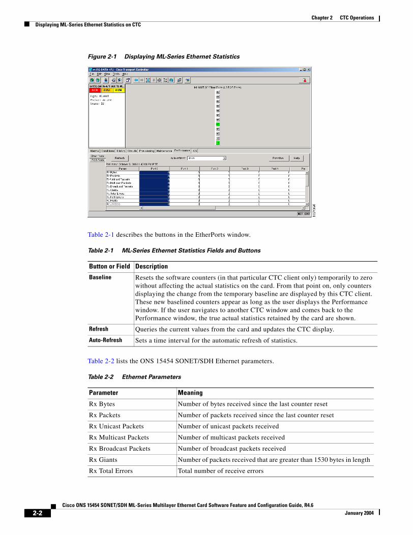
Displaying ML-Series Ethernet Statistics on CTCThe Ethernet statistics window (Figure 2-1 on page 2-2) lists Ethernet port-level statistics. The ML-Series Ethernet ports are zero based. Display the CTC card view for the ML-Series card and click the Performance > Ether Ports tabs to display the window.
2-1e Feature and Configuration Guide, R4.6
Chapter 2 CTC OperationsDisplaying ML-Series Ethernet Statistics on CTC
Figure 2-1 Displaying ML-Series Ethernet Statistics
Table 2-1 describes the buttons in the EtherPorts window.
Table 2-2 lists the ONS 15454 SONET/SDH Ethernet parameters.
Table 2-1 ML-Series Ethernet Statistics Fields and Buttons
Button or Field Description
Baseline Resets the software counters (in that particular CTC client only) temporarily to zero without affecting the actual statistics on the card. From that point on, only counters displaying the change from the temporary baseline are displayed by this CTC client. These new baselined counters appear as long as the user displays the Performance window. If the user navigates to another CTC window and comes back to the Performance window, the true actual statistics retained by the card are shown.
Refresh Queries the current values from the card and updates the CTC display.
Auto-Refresh Sets a time interval for the automatic refresh of statistics.
Table 2-2 Ethernet Parameters
Parameter Meaning
Rx Bytes Number of bytes received since the last counter reset
Rx Packets Number of packets received since the last counter reset
Rx Unicast Packets Number of unicast packets received
Rx Multicast Packets Number of multicast packets received
Rx Broadcast Packets Number of broadcast packets received
Rx Giants Number of packets received that are greater than 1530 bytes in length
Rx Total Errors Total number of receive errors
2-2Cisco ONS 15454 SONET/SDH ML-Series Multilayer Ethernet Card Software Feature and Configuration Guide, R4.6
January 2004
Chapter 2 CTC OperationsDisplaying ML-Series POS Statistics on CTC
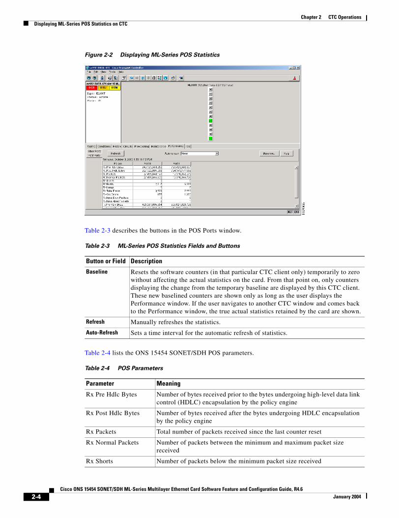
Displaying ML-Series POS Statistics on CTCThe POS statistics window lists POS port-level statistics (Figure 2-2). Display the CTC card view for the ML-Series card and click the Performance > POS Ports tabs to display the window.
Rx FCS Errors Number of packets with a frame check sequence (FCS) error
Rx Runts Total number of frames received that are less than 64 bytes in length and have a cyclic redundancy check (CRC) error
Rx Jabbers Total number of frames received that exceed the maximum 1548 bytes and contain CRC errors
Rx Align Errors Number of received packets with alignment errors
Tx Bytes Number of bytes transmitted since the last counter reset
Tx Packets Number of packets transmitted since the last counter reset
Tx Unicast Packets Number of unicast packets transmitted
Tx Multicast Packets Number of multicast packets transmitted
Tx Broadcast Packets Number of broadcast packets transmitted
Tx Giants Number of packets transmitted that are greater than 1548 bytes in length
Tx Collisions Number of transmitted packets that collided
Port Drop Counts Number of received frames dropped at the port level
Rx Pause Frames Number of received pause frames (applies only to the ML1000-2 Ethernet ports)
Rx Threshold Oversizes Number of received packets larger than the ML-Series remote monitoring (RMON) threshold (applies only to the ML1000-2 Ethernet ports)
Rx GMAC Drop Counts Number of received frames dropped by MAC module (applies only to the ML1000-2 Ethernet ports)
Tx Pause Frames Number of transmitted pause frames (applies only to the ML1000-2 Ethernet ports)
Table 2-2 Ethernet Parameters (continued)
Parameter Meaning
2-3Cisco ONS 15454 SONET/SDH ML-Series Multilayer Ethernet Card Software Feature and Configuration Guide, R4.6
January 2004
Chapter 2 CTC OperationsDisplaying ML-Series POS Statistics on CTC
Figure 2-2 Displaying ML-Series POS Statistics
Table 2-3 describes the buttons in the POS Ports window.
Table 2-4 lists the ONS 15454 SONET/SDH POS parameters.
Table 2-3 ML-Series POS Statistics Fields and Buttons
Button or Field Description
Baseline Resets the software counters (in that particular CTC client only) temporarily to zero without affecting the actual statistics on the card. From that point on, only counters displaying the change from the temporary baseline are displayed by this CTC client. These new baselined counters are shown only as long as the user displays the Performance window. If the user navigates to another CTC window and comes back to the Performance window, the true actual statistics retained by the card are shown.
Refresh Manually refreshes the statistics.
Auto-Refresh Sets a time interval for the automatic refresh of statistics.
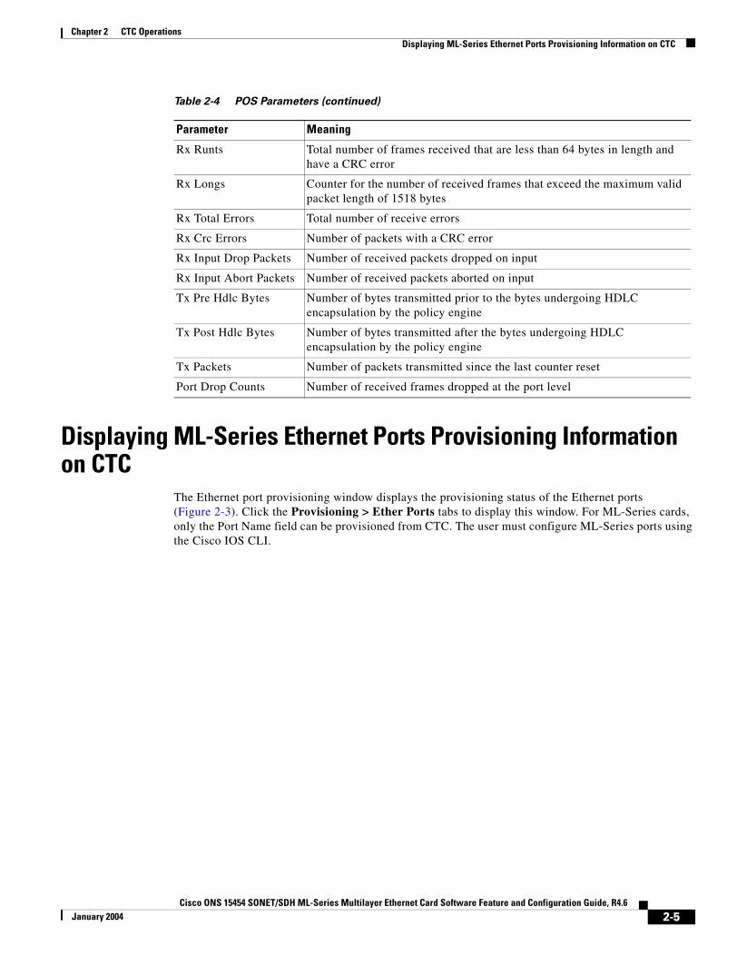
Table 2-4 POS Parameters
Parameter Meaning
Rx Pre Hdlc Bytes Number of bytes received prior to the bytes undergoing high-level data link control (HDLC) encapsulation by the policy engine
Rx Post Hdlc Bytes Number of bytes received after the bytes undergoing HDLC encapsulation by the policy engine
Rx Packets Total number of packets received since the last counter reset
Rx Normal Packets Number of packets between the minimum and maximum packet size received
Rx Shorts Number of packets below the minimum packet size received
2-4Cisco ONS 15454 SONET/SDH ML-Series Multilayer Ethernet Card Software Feature and Configuration Guide, R4.6
January 2004
Chapter 2 CTC OperationsDisplaying ML-Series Ethernet Ports Provisioning Information on CTC
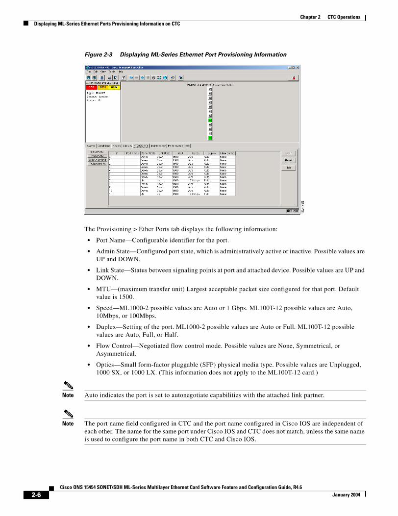
Displaying ML-Series Ethernet Ports Provisioning Information on CTC
The Ethernet port provisioning window displays the provisioning status of the Ethernet ports (Figure 2-3). Click the Provisioning > Ether Ports tabs to display this window. For ML-Series cards, only the Port Name field can be provisioned from CTC. The user must configure ML-Series ports using the Cisco IOS CLI.
Rx Runts Total number of frames received that are less than 64 bytes in length and have a CRC error
Rx Longs Counter for the number of received frames that exceed the maximum valid packet length of 1518 bytes
Rx Total Errors Total number of receive errors
Rx Crc Errors Number of packets with a CRC error
Rx Input Drop Packets Number of received packets dropped on input
Rx Input Abort Packets Number of received packets aborted on input
Tx Pre Hdlc Bytes Number of bytes transmitted prior to the bytes undergoing HDLC encapsulation by the policy engine
Tx Post Hdlc Bytes Number of bytes transmitted after the bytes undergoing HDLC encapsulation by the policy engine
Tx Packets Number of packets transmitted since the last counter reset
Port Drop Counts Number of received frames dropped at the port level
Table 2-4 POS Parameters (continued)
Parameter Meaning
2-5Cisco ONS 15454 SONET/SDH ML-Series Multilayer Ethernet Card Software Feature and Configuration Guide, R4.6
January 2004
Chapter 2 CTC OperationsDisplaying ML-Series Ethernet Ports Provisioning Information on CTC
Figure 2-3 Displaying ML-Series Ethernet Port Provisioning Information
The Provisioning > Ether Ports tab displays the following information:
• Port Name—Configurable identifier for the port.
• Admin State—Configured port state, which is administratively active or inactive. Possible values are UP and DOWN.
• Link State—Status between signaling points at port and attached device. Possible values are UP and DOWN.
• MTU—(maximum transfer unit) Largest acceptable packet size configured for that port. Default value is 1500.
• Speed—ML1000-2 possible values are Auto or 1 Gbps. ML100T-12 possible values are Auto, 10Mbps, or 100Mbps.
• Duplex—Setting of the port. ML1000-2 possible values are Auto or Full. ML100T-12 possible values are Auto, Full, or Half.
• Flow Control—Negotiated flow control mode. Possible values are None, Symmetrical, or Asymmetrical.
• Optics—Small form-factor pluggable (SFP) physical media type. Possible values are Unplugged, 1000 SX, or 1000 LX. (This information does not apply to the ML100T-12 card.)
Note Auto indicates the port is set to autonegotiate capabilities with the attached link partner.
Note The port name field configured in CTC and the port name configured in Cisco IOS are independent of each other. The name for the same port under Cisco IOS and CTC does not match, unless the same name is used to configure the port name in both CTC and Cisco IOS.
2-6Cisco ONS 15454 SONET/SDH ML-Series Multilayer Ethernet Card Software Feature and Configuration Guide, R4.6
January 2004

Chapter 2 CTC OperationsDisplaying ML-Series POS Ports Provisioning Information on CTC
Note When set to autonegotiate, the ML1000-2 might show Auto in the speed and duplex columns of the Ether ports provisioning screen. This indicates that the ML1000-2 is set to autonegotiate flow control with the link partner. It does not mean the speed or duplex mode of the card will vary from the 1-Gbps, full duplex characteristics of Gigabit Ethernet.
Displaying ML-Series POS Ports Provisioning Information on CTC
The POS ports provisioning window displays the provisioning status of the card’s POS ports (Figure 2-4). Click the Provisioning > POS Ports tabs to display this window. For ML-Series cards, only the POS Port Name field can be provisioned from CTC. The user must configure ML-Series ports through the Cisco IOS CLI.
Figure 2-4 Displaying POS Port Provisioning Information
The Provisioning > POS Ports tab displays the following information:
• Port Name—Configurable identifier for the port.
• Admin State—Configured administrative port state, which is active or inactive. Possible values are UP and DOWN.
• Link State—Status between signaling points at the port and an attached device. Possible values are UP and DOWN.
• MTU—(maximum transfer unit) Largest acceptable packet size configured for that port. Maximum setting is 9000 and default size is 1500 for the G-Series card compatible encapsulation (LEX) and 4470 for Cisco HDLC and point-to-point protocol/bridging control protocol (PPP/BCP) encapsulation. The MTU value is 0 until the POS port is used in creating a circuit.
2-7Cisco ONS 15454 SONET/SDH ML-Series Multilayer Ethernet Card Software Feature and Configuration Guide, R4.6
January 2004

Chapter 2 CTC OperationsManaging SONET/SDH Alarms
Note POS interfaces are first created when a CTC STS/STM circuit is provisioned.
Note The port name field configured in CTC and the port name configured in Cisco IOS are independent of each other. The name for the same port under Cisco IOS and CTC does not match, unless the same name is used to configure the port name in both CTC and Cisco IOS.
Managing SONET/SDH AlarmsCTC manages the ML-Series SONET/SDH alarm behavior in the same manner as it manages alarm behavior for other ONS 15454 SONET/SDH cards. Refer to the “Manage Alarms” chapter of the Cisco ONS 15454 Procedure Guide or the Cisco ONS 15454 SDH Procedure Guide for detailed information. For information on specific alarms, refer to the “Alarm Troubleshooting” chapter of the Cisco ONS 15454 Troubleshooting Guide or Cisco ONS 15454 SDH Troubleshooting Guide for detailed information.
To view the window, click the Ether Alarming > Provisioning tabs for the Ethernet ports or POS Alarming > Provisioning tabs for the POS ports. Figure 2-5 shows the Ethernet ports alarming pane.
Figure 2-5 Managing ML-Series SONET/SDH Alarms
2-8Cisco ONS 15454 SONET/SDH ML-Series Multilayer Ethernet Card Software Feature and Configuration Guide, R4.6
January 2004
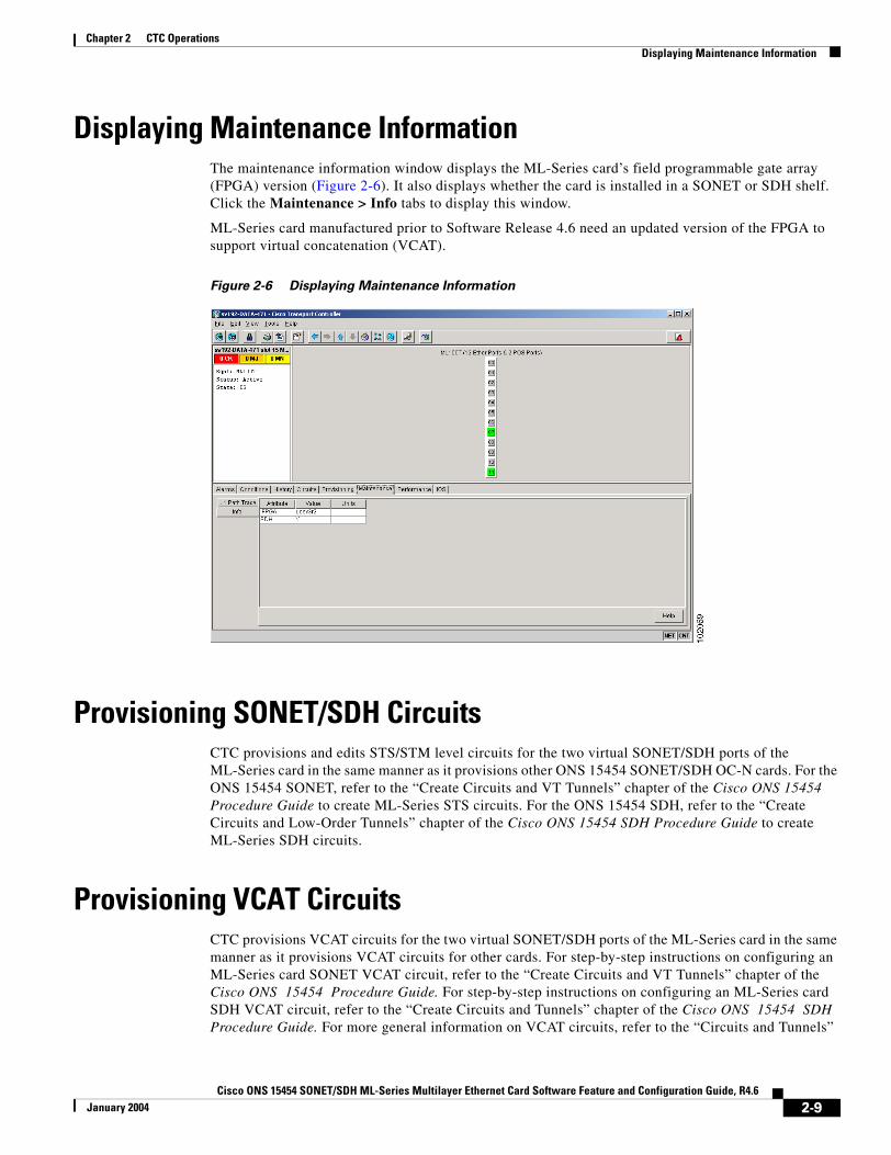
Chapter 2 CTC OperationsDisplaying Maintenance Information
Displaying Maintenance InformationThe maintenance information window displays the ML-Series card’s field programmable gate array (FPGA) version (Figure 2-6). It also displays whether the card is installed in a SONET or SDH shelf. Click the Maintenance > Info tabs to display this window.
ML-Series card manufactured prior to Software Release 4.6 need an updated version of the FPGA to support virtual concatenation (VCAT).
Figure 2-6 Displaying Maintenance Information
Provisioning SONET/SDH Circuits CTC provisions and edits STS/STM level circuits for the two virtual SONET/SDH ports of the ML-Series card in the same manner as it provisions other ONS 15454 SONET/SDH OC-N cards. For the ONS 15454 SONET, refer to the “Create Circuits and VT Tunnels” chapter of the Cisco ONS 15454 Procedure Guide to create ML-Series STS circuits. For the ONS 15454 SDH, refer to the “Create Circuits and Low-Order Tunnels” chapter of the Cisco ONS 15454 SDH Procedure Guide to create ML-Series SDH circuits.
Provisioning VCAT Circuits CTC provisions VCAT circuits for the two virtual SONET/SDH ports of the ML-Series card in the same manner as it provisions VCAT circuits for other cards. For step-by-step instructions on configuring an ML-Series card SONET VCAT circuit, refer to the “Create Circuits and VT Tunnels” chapter of the Cisco ONS 15454 Procedure Guide. For step-by-step instructions on configuring an ML-Series card SDH VCAT circuit, refer to the “Create Circuits and Tunnels” chapter of the Cisco ONS 15454 SDH Procedure Guide. For more general information on VCAT circuits, refer to the “Circuits and Tunnels”
2-9Cisco ONS 15454 SONET/SDH ML-Series Multilayer Ethernet Card Software Feature and Configuration Guide, R4.6
January 2004

Chapter 2 CTC OperationsJ1 Path Trace
chapter of the Cisco ONS 15454 Reference Guide or the Cisco ONS 15454 SDH Reference Guide. For a summary of the ML-Series card VCAT capabilities, refer to the “VCAT” section on page 1-8. For a summary of the SW-LCAS feature on the ML-Series card, refer to the “SW-LCAS” section on page 1-7.
J1 Path TraceThe J1 Path Trace is a repeated, fixed-length string comprised of 64 consecutive J1 bytes. You can use the string to monitor interruptions or changes to SONET/SDH circuit traffic. For information on J1 Path Trace, refer to the “Circuits and Tunnels” chapter of the Cisco ONS 15454 Reference Guide or the Cisco ONS 15454 SDH Reference Guide.
2-10Cisco ONS 15454 SONET/SDH ML-Series Multilayer Ethernet Card Software Feature and Configuration Guide, R4.6
January 2004
Cisco ONS 15454 SONET/SDH ML-Series Multilayer Ethernet Card SoftwarJanuary 2004
C H A P T E R 3
Initial ConfigurationThis chapter describes the initial configuration of the ML-Series card and contains the following major sections:
• Hardware Installation, page 3-1
• Cisco IOS on the ML-Series Card, page 3-1
• Startup Configuration File, page 3-6
• Multiple Microcode Images, page 3-11
• Using the Command Modes, page 3-14
Hardware InstallationThis section lists hardware installation tasks, including booting up the ML-Series card. Because ONS 15454 SONET/SDH card slots can be preprovisioned for an ML-Series line card, the following physical operations can be performed before or after the provisioning of the slot has taken place.
1. Install the ML-Series card into the ONS 15454 SONET/SDH. See Chapter 2, “Install Cards and Fiber-Optic Cable” of the Cisco ONS 15454 Procedure Guide or Cisco ONS 15454 SDH Procedure Guide for information.
2. Connect the Ethernet cables to the ML-Series card.
3. Connect the console terminal to the ML-Series card (optional).
Note A NO-CONFIG condition is reported in CTC under the Alarms pane when an ML-Series card is inserted and no valid Cisco IOS startup configuration file exists. Loading or creating this file clears the condition. See the “Startup Configuration File” section on page 3-6 for information on loading or creating the file.
Cisco IOS on the ML-Series CardThe Cisco IOS software image used by the ML-Series card is not permanently stored on the ML-Series card but in the flash memory of the TCC2 card. During a hard reset, when a card is physically removed and reinserted, the Cisco IOS software image is downloaded from the flash memory of the TCC2 to the memory cache of the ML-Series card. The cached image is then decompressed and initialized for use by the ML-Series card.
3-1e Feature and Configuration Guide, R4.6

Chapter 3 Initial ConfigurationOpening a Cisco IOS Session Using CTC
During a soft reset, when the ML-Series card is reset through CTC or Cisco IOS command line interface (CLI) commands, the ML-Series card checks its cache for a Cisco IOS image. If a valid and current Cisco IOS image exists, the ML-Series card decompresses and initializes the image. If the image does not exist, the ML-Series requests a new copy of the Cisco IOS image from the TCC. Caching the Cisco IOS image provides a significant time savings when a warm reset is performed.
There are four ways to access the ML-Series card Cisco IOS configuration: opening a Cisco IOS session on CTC, telnetting to the IP Address and slot number plus 2000, telnetting to a configured management port, or directly connecting to the console port.
Opening a Cisco IOS Session Using CTCUsers can initiate a Cisco IOS CLI session for the ML-Series card using CTC. Click the IOS tab at the card-level CTC view, then click the Open IOS Command Line Interface (CLI) button (Figure 3-1). A window opens and a standard Cisco IOS CLI User EXEC command mode prompt appears.
Note A Cisco IOS startup configuration file must be loaded and the ML-Series card must be installed and initialized prior to opening a Cisco IOS CLI session on CTC. See the “Startup Configuration File” section on page 3-6 for more information.
Figure 3-1 CTC IOS Window
Telnetting to the Node IP Address and Slot NumberUsers can telnet to the Cisco IOS CLI using the IP address and the slot number of the ONS 15454 SONET/SDH plus 2000.
3-2Cisco ONS 15454 SONET/SDH ML-Series Multilayer Ethernet Card Software Feature and Configuration Guide, R4.6
January 2004
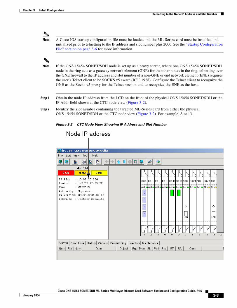
Chapter 3 Initial ConfigurationTelnetting to the Node IP Address and Slot Number
Note A Cisco IOS startup configuration file must be loaded and the ML-Series card must be installed and initialized prior to telnetting to the IP address and slot number plus 2000. See the “Startup Configuration File” section on page 3-6 for more information.
Note If the ONS 15454 SONET/SDH node is set up as a proxy server, where one ONS 15454 SONET/SDH node in the ring acts as a gateway network element (GNE) for the other nodes in the ring, telnetting over the GNE firewall to the IP address and slot number of a non-GNE or end network element (ENE) requires the user’s Telnet client to be SOCKS v5 aware (RFC 1928). Configure the Telnet client to recognize the GNE as the Socks v5 proxy for the Telnet session and to recognize the ENE as the host.
Step 1 Obtain the node IP address from the LCD on the front of the physical ONS 15454 SONET/SDH or the IP Addr field shown at the CTC node view (Figure 3-2).
Step 2 Identify the slot number containing the targeted ML-Series card from either the physical ONS 15454 SONET/SDH or the CTC node view (Figure 3-2). For example, Slot 13.
Figure 3-2 CTC Node View Showing IP Address and Slot Number
3-3Cisco ONS 15454 SONET/SDH ML-Series Multilayer Ethernet Card Software Feature and Configuration Guide, R4.6
January 2004

Chapter 3 Initial ConfigurationTelnetting to a Management Port
Step 3 Use the IP address and the total of the slot number plus 2000 as the Telnet address in your preferred communication program. For example, for an IP address of 10.92.18.124 and Slot 13, you would enter or telnet 10.92.18.124 2013.
Telnetting to a Management Port Users can access the ML-Series through a standard Cisco IOS management port in the same manner as other Cisco IOS platforms. For further details about configuring ports and lines for management access, refer to the Cisco IOS Configuration Fundamentals Configuration Guide.
As a security measure, the vty lines used for Telnet access are not fully configured. In order to gain Telnet access to the ML-Series card, you must configure the vty lines via the serial console connection or preload a startup-configuration file that configures the vty lines. A port on the ML-Series must first be configured as the management port; see “Configuring the Management Port” section on page 3-8 or the “Loading a Cisco IOS Startup Configuration File Through CTC” section on page 3-9.
ML-Series IOS CLI Console PortThe ML-Series card has an RJ-11 serial console port on the card faceplate labeled CONSOLE. The console port is wired as data circuit-terminating equipment (DCE). It enables communication from the serial port of a PC or workstation running terminal emulation software to the Cisco IOS CLI on a specific ML-Series card.
RJ-11 to RJ-45 Console Cable Adapter
Due to space limitations on the ML-Series card faceplate, the console port is an RJ-11 modular jack instead of the more common RJ-45 modular jack. Cisco supplies an RJ-11 to RJ-45 console cable adapter (P/N 15454-CONSOLE-02) with each ML-Series card. After connecting the adapter, the console port functions like the standard Cisco RJ-45 console port. Figure 3-3 shows the RJ-11 to RJ-45 console cable adapter.
Figure 3-3 Console Cable Adapter
Table 3-1 shows the mapping of the RJ-11 pins to the RJ-45 pins.
7897
0
Table 3-1 RJ-11 to RJ-45 Pin Mapping
RJ-11 Pin RJ-45 Pin
1 1
2 2
3 3
3-4Cisco ONS 15454 SONET/SDH ML-Series Multilayer Ethernet Card Software Feature and Configuration Guide, R4.6
January 2004
Chapter 3 Initial ConfigurationML-Series IOS CLI Console Port
Connecting a PC or Terminal to the Console Port
Use the supplied cable, an RJ-11 to RJ-45 console cable adapter, and a DB-9 adapter to connect a PC to the ML-Series console port.
The PC must support VT100 terminal emulation. The terminal-emulation software—frequently a PC application such as HyperTerminal or Procomm Plus—makes communication between the ML-Series and your PC or terminal possible during the setup program.
Step 1 Configure the data rate and character format of the PC or terminal to match these console port default settings:
• 9600 baud
• 8 data bits
• 1 stop bit
• No parity
Step 2 Insert the RJ-45 connector of the supplied cable into the female end of the supplied console cable adapter.
Step 3 Insert the RJ-11 modular plug end of the supplied console cable adapter into the RJ-11 serial console port, labeled CONSOLE, on the ML-Series card faceplate. Figure 3-4 shows the ML1000-2 faceplate with console port. The console port on the ML100-12 is at the bottom of the card faceplate.
4 4
None 5
5 6
None 7
6 8
Table 3-1 RJ-11 to RJ-45 Pin Mapping (continued)
RJ-11 Pin RJ-45 Pin
3-5Cisco ONS 15454 SONET/SDH ML-Series Multilayer Ethernet Card Software Feature and Configuration Guide, R4.6
January 2004
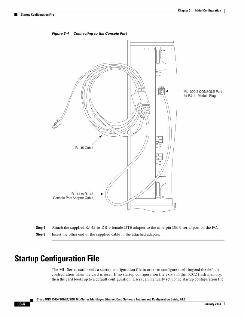
Chapter 3 Initial ConfigurationStartup Configuration File
Figure 3-4 Connecting to the Console Port
Step 4 Attach the supplied RJ-45-to-DB-9 female DTE adapter to the nine-pin DB-9 serial port on the PC.
Step 5 Insert the other end of the supplied cable in the attached adapter.
Startup Configuration FileThe ML-Series card needs a startup configuration file in order to configure itself beyond the default configuration when the card is reset. If no startup configuration file exists in the TCC2 flash memory, then the card boots up to a default configuration. Users can manually set up the startup configuration file
ML10002
FAIL
ACT
CONSOLE
ACT
LINK
TX
1
RX
ACT
LINK
TX
2
RX
7899
4
RJ-45 Cable
RJ-11 to RJ-45Console Port Adapter Cable
ML1000-2 CONSOLE Portfor RJ-11 Module Plug
3-6Cisco ONS 15454 SONET/SDH ML-Series Multilayer Ethernet Card Software Feature and Configuration Guide, R4.6
January 2004

Chapter 3 Initial ConfigurationManually Creating a Startup Configuration File Through the Serial Console Port
through the serial console port and the Cisco IOS CLI configuration mode or load a Cisco IOS supplied sample startup configuration file through CTC. A running configuration becomes a startup configuration file when saved with a copy running-config startup-config command.
It is not possible to establish a Telnet connection to the ML-Series card until a startup configuration filed is loaded onto the ML-Series card. Access is available through the console port.
Caution The copy running-config startup-config command saves a startup configuration file to the flash memory on the ML-Series card. This operation is confirmed by the appearance of [OK] in the Cisco IOS CLI session. The startup configuration file is also saved to the ONS node’s database restoration file after approximately 30 additional seconds.
Caution Accessing the read-only memory monitor mode (ROMMON) on the ML-Series card without the assistance of Cisco personnel is not recommended. This mode allows actions that can render the ML-Series card inoperable. The ML-Series card ROMMON is preconfigured to boot the correct Cisco IOS software image for the ML-Series card.
Note When the running configuration file is altered, a RUNCFG-SAVENEED condition appears in CTC. This condition is a reminder to enter a copy running-config startup-config command in the Cisco IOS CLI, or the changes will be lost when the ML-Series card reboots.
Manually Creating a Startup Configuration File Through the Serial Console PortConfiguration through the serial console port is familiar to those who have worked with other products using Cisco IOS. At the end of the configuration procedure, the copy running-config startup-config command saves a startup configuration file.
The serial console port gives the user visibility to the entire booting process of the ML-Series card. During initialization the ML-Series card first checks for a locally, valid cached copy of Cisco IOS. It then either downloads the Cisco IOS software image from the TCC2 or proceeds directly to decompressing and initializing the image. Following Cisco IOS initialization the CLI prompt appears, at which time the user can enter the Cisco IOS CLI configuration mode and setup the basic ML-Series configuration.
Passwords
There are two types of passwords that you can configure for an ML-Series card: an enable password and an enable secret password. For maximum security, make the enable password different from the enable secret password.
• Enable password—The enable password is a nonencrypted password. It can contain any number of uppercase and lowercase alphanumeric characters. Give the enable password only to users permitted to make configuration changes to the ML-Series card.
• Enable secret password—The enable secret password is a secure, encrypted password. By setting an encrypted password, you can prevent unauthorized configuration changes. On systems running Cisco IOS software, you must enter the enable secret password before you can access global configuration mode.
3-7Cisco ONS 15454 SONET/SDH ML-Series Multilayer Ethernet Card Software Feature and Configuration Guide, R4.6
January 2004
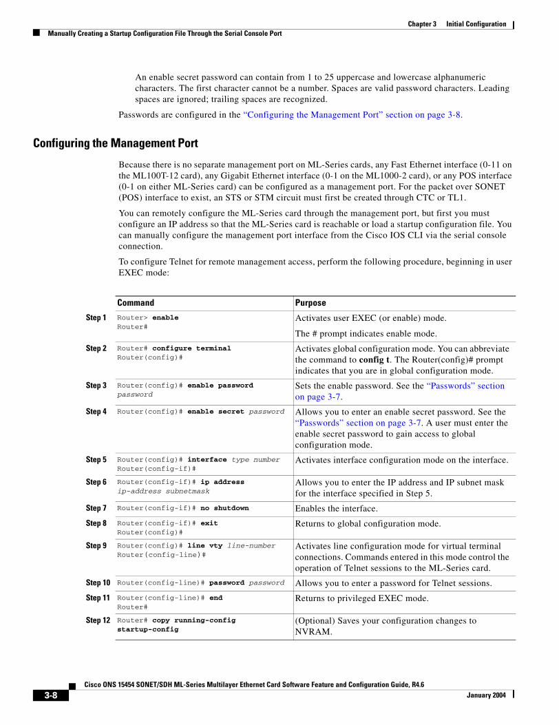
Chapter 3 Initial ConfigurationManually Creating a Startup Configuration File Through the Serial Console Port
An enable secret password can contain from 1 to 25 uppercase and lowercase alphanumeric characters. The first character cannot be a number. Spaces are valid password characters. Leading spaces are ignored; trailing spaces are recognized.
Passwords are configured in the “Configuring the Management Port” section on page 3-8.
Configuring the Management Port
Because there is no separate management port on ML-Series cards, any Fast Ethernet interface (0-11 on the ML100T-12 card), any Gigabit Ethernet interface (0-1 on the ML1000-2 card), or any POS interface (0-1 on either ML-Series card) can be configured as a management port. For the packet over SONET (POS) interface to exist, an STS or STM circuit must first be created through CTC or TL1.
You can remotely configure the ML-Series card through the management port, but first you must configure an IP address so that the ML-Series card is reachable or load a startup configuration file. You can manually configure the management port interface from the Cisco IOS CLI via the serial console connection.
To configure Telnet for remote management access, perform the following procedure, beginning in user EXEC mode:
Command Purpose
Step 1 Router> enable Router#
Activates user EXEC (or enable) mode.
The # prompt indicates enable mode.
Step 2 Router# configure terminalRouter(config)#
Activates global configuration mode. You can abbreviate the command to config t. The Router(config)# prompt indicates that you are in global configuration mode.
Step 3 Router(config)# enable password password
Sets the enable password. See the “Passwords” section on page 3-7.
Step 4 Router(config)# enable secret password Allows you to enter an enable secret password. See the “Passwords” section on page 3-7. A user must enter the enable secret password to gain access to global configuration mode.
Step 5 Router(config)# interface type numberRouter(config-if)#
Activates interface configuration mode on the interface.
Step 6 Router(config-if)# ip address ip-address subnetmask
Allows you to enter the IP address and IP subnet mask for the interface specified in Step 5.
Step 7 Router(config-if)# no shutdown Enables the interface.
Step 8 Router(config-if)# exitRouter(config)#
Returns to global configuration mode.
Step 9 Router(config)# line vty line-numberRouter(config-line)#
Activates line configuration mode for virtual terminal connections. Commands entered in this mode control the operation of Telnet sessions to the ML-Series card.
Step 10 Router(config-line)# password password Allows you to enter a password for Telnet sessions.
Step 11 Router(config-line)# endRouter#
Returns to privileged EXEC mode.
Step 12 Router# copy running-config startup-config
(Optional) Saves your configuration changes to NVRAM.
3-8Cisco ONS 15454 SONET/SDH ML-Series Multilayer Ethernet Card Software Feature and Configuration Guide, R4.6
January 2004
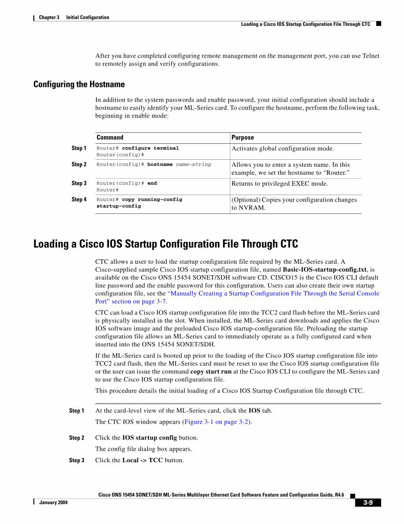
Chapter 3 Initial ConfigurationLoading a Cisco IOS Startup Configuration File Through CTC
After you have completed configuring remote management on the management port, you can use Telnet to remotely assign and verify configurations.
Configuring the Hostname
In addition to the system passwords and enable password, your initial configuration should include a hostname to easily identify your ML-Series card. To configure the hostname, perform the following task, beginning in enable mode:
Loading a Cisco IOS Startup Configuration File Through CTCCTC allows a user to load the startup configuration file required by the ML-Series card. A Cisco-supplied sample Cisco IOS startup configuration file, named Basic-IOS-startup-config.txt, is available on the Cisco ONS 15454 SONET/SDH software CD. CISCO15 is the Cisco IOS CLI default line password and the enable password for this configuration. Users can also create their own startup configuration file, see the “Manually Creating a Startup Configuration File Through the Serial Console Port” section on page 3-7.
CTC can load a Cisco IOS startup configuration file into the TCC2 card flash before the ML-Series card is physically installed in the slot. When installed, the ML-Series card downloads and applies the Cisco IOS software image and the preloaded Cisco IOS startup-configuration file. Preloading the startup configuration file allows an ML-Series card to immediately operate as a fully configured card when inserted into the ONS 15454 SONET/SDH.
If the ML-Series card is booted up prior to the loading of the Cisco IOS startup configuration file into TCC2 card flash, then the ML-Series card must be reset to use the Cisco IOS startup configuration file or the user can issue the command copy start run at the Cisco IOS CLI to configure the ML-Series card to use the Cisco IOS startup configuration file.
This procedure details the initial loading of a Cisco IOS Startup Configuration file through CTC.
Step 1 At the card-level view of the ML-Series card, click the IOS tab.
The CTC IOS window appears (Figure 3-1 on page 3-2).
Step 2 Click the IOS startup config button.
The config file dialog box appears.
Step 3 Click the Local -> TCC button.
Command Purpose
Step 1 Router# configure terminalRouter(config)#
Activates global configuration mode.
Step 2 Router(config)# hostname name-string Allows you to enter a system name. In this example, we set the hostname to “Router.”
Step 3 Router(config)# endRouter#
Returns to privileged EXEC mode.
Step 4 Router# copy running-config startup-config
(Optional) Copies your configuration changes to NVRAM.
3-9Cisco ONS 15454 SONET/SDH ML-Series Multilayer Ethernet Card Software Feature and Configuration Guide, R4.6
January 2004

Chapter 3 Initial ConfigurationLoading a Cisco IOS Startup Configuration File Through CTC
Step 4 The sample Cisco IOS startup configuration file can be installed from either the ONS 15454 SONET/SDH software CD or from a PC or network folder:
• To install the Cisco supplied startup config file from the ONS 15454 SONET/SDH software CD, insert the CD into the CD drive of the PC or workstation. Using the CTC config file dialog, navigate to the CD drive of the PC or workstation and double-click the Basic-IOS-startup-config.txt file.
• To install the Cisco supplied config file from a PC or network folder, navigate to the folder containing the desired Cisco IOS startup config file and double-click the desired Cisco IOS startup config file.
Step 5 At the Are you sure? dialog box, click the Yes button.
The Directory and Filename fields on the configuration file dialog update to reflect that the Cisco IOS startup config file is loaded onto the TCC2.
Step 6 Load the IOS startup config file from the TCC2 to the ML-Series card:
a. If the ML-Series card has already been installed, right-click on the ML-Series card at the node level CTC view and select Reset Card.
After the reset, the ML-Series card runs under the newly loaded Cisco IOS startup config.
b. If the ML-Series card is not yet installed, installing the ML-Series card into the slot loads and runs the newly loaded Cisco IOS startup configuration on the ML-Series card.
Note When the Cisco IOS startup configuration file is downloaded and parsed at initialization, if there is an error in the parsing of this file, an ERROR-CONFIG alarm is reported and appears under the CTC alarms pane or in TL1. No other Cisco IOS error messages regarding the parsing of text are reported to the CTC or in TL1. An experienced Cisco IOS user can locate and troubleshoot the line in the startup configuration file that produced the parsing error by opening the Cisco IOS CLI and entering a copy start run command.
Note A standard ONS 15454 SONET/SDH database restore reinstalls the Cisco IOS startup config file on the TCC2, but does not implement the Cisco IOS startup config on the ML-Series. Complete Step 6 to load the Cisco IOS startup config file from the TCC2 to the ML-Series card.
3-10Cisco ONS 15454 SONET/SDH ML-Series Multilayer Ethernet Card Software Feature and Configuration Guide, R4.6
January 2004
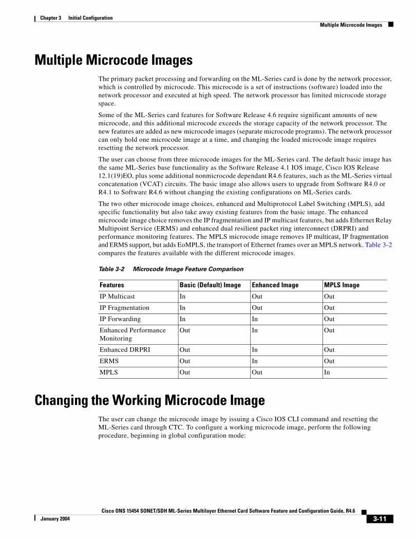
Chapter 3 Initial ConfigurationMultiple Microcode Images
Multiple Microcode ImagesThe primary packet processing and forwarding on the ML-Series card is done by the network processor, which is controlled by microcode. This microcode is a set of instructions (software) loaded into the network processor and executed at high speed. The network processor has limited microcode storage space.
Some of the ML-Series card features for Software Release 4.6 require significant amounts of new microcode, and this additional microcode exceeds the storage capacity of the network processor. The new features are added as new microcode images (separate microcode programs). The network processor can only hold one microcode image at a time, and changing the loaded microcode image requires resetting the network processor.
The user can choose from three microcode images for the ML-Series card. The default basic image has the same ML-Series base functionality as the Software Release 4.1 IOS image, Cisco IOS Release 12.1(19)EO, plus some additional nonmicrocode dependant R4.6 features, such as the ML-Series virtual concatenation (VCAT) circuits. The basic image also allows users to upgrade from Software R4.0 or R4.1 to Software R4.6 without changing the existing configurations on ML-Series cards.
The two other microcode image choices, enhanced and Multiprotocol Label Switching (MPLS), add specific functionality but also take away existing features from the basic image. The enhanced microcode image choice removes the IP fragmentation and IP multicast features, but adds Ethernet Relay Multipoint Service (ERMS) and enhanced dual resilient packet ring interconnect (DRPRI) and performance monitoring features. The MPLS microcode image removes IP multicast, IP fragmentation and ERMS support, but adds EoMPLS, the transport of Ethernet frames over an MPLS network. Table 3-2 compares the features available with the different microcode images.
Changing the Working Microcode ImageThe user can change the microcode image by issuing a Cisco IOS CLI command and resetting the ML-Series card through CTC. To configure a working microcode image, perform the following procedure, beginning in global configuration mode:
Table 3-2 Microcode Image Feature Comparison
Features Basic (Default) Image Enhanced Image MPLS Image
IP Multicast In Out Out
IP Fragmentation In Out Out
IP Forwarding In In Out
Enhanced Performance Monitoring
Out In Out
Enhanced DRPRI Out In Out
ERMS Out In Out
MPLS Out Out In
3-11Cisco ONS 15454 SONET/SDH ML-Series Multilayer Ethernet Card Software Feature and Configuration Guide, R4.6
January 2004
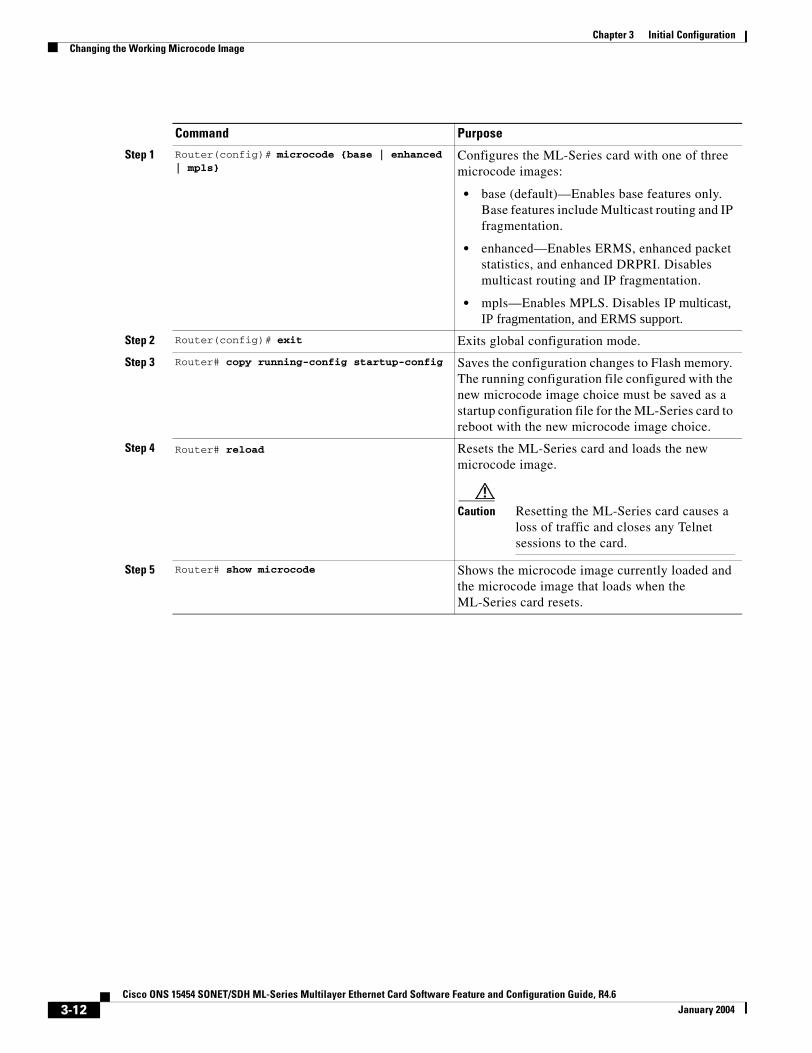
Chapter 3 Initial ConfigurationChanging the Working Microcode Image
Command Purpose
Step 1 Router(config)# microcode {base | enhanced | mpls}
Configures the ML-Series card with one of three microcode images:
• base (default)—Enables base features only. Base features include Multicast routing and IP fragmentation.
• enhanced—Enables ERMS, enhanced packet statistics, and enhanced DRPRI. Disables multicast routing and IP fragmentation.
• mpls—Enables MPLS. Disables IP multicast, IP fragmentation, and ERMS support.
Step 2 Router(config)# exit Exits global configuration mode.
Step 3 Router# copy running-config startup-config Saves the configuration changes to Flash memory. The running configuration file configured with the new microcode image choice must be saved as a startup configuration file for the ML-Series card to reboot with the new microcode image choice.
Step 4 Router# reload Resets the ML-Series card and loads the new microcode image.
Caution Resetting the ML-Series card causes a loss of traffic and closes any Telnet sessions to the card.
Step 5 Router# show microcode Shows the microcode image currently loaded and the microcode image that loads when the ML-Series card resets.
3-12Cisco ONS 15454 SONET/SDH ML-Series Multilayer Ethernet Card Software Feature and Configuration Guide, R4.6
January 2004
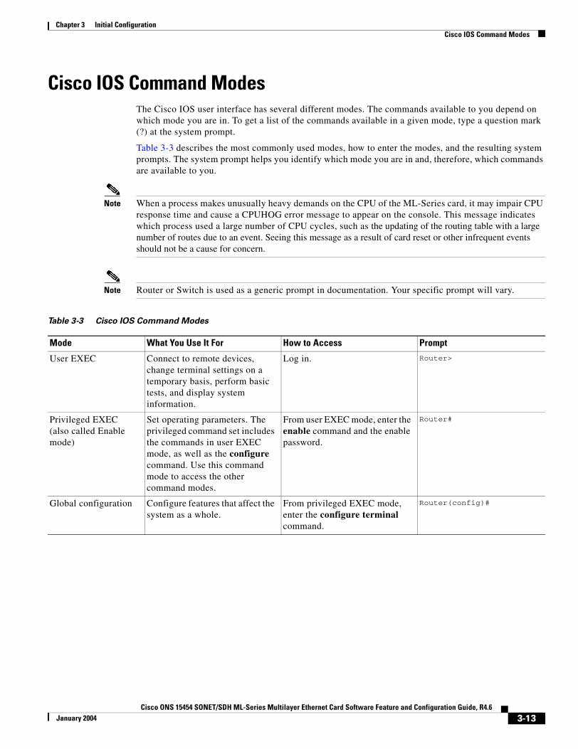
Chapter 3 Initial ConfigurationCisco IOS Command Modes
Cisco IOS Command ModesThe Cisco IOS user interface has several different modes. The commands available to you depend on which mode you are in. To get a list of the commands available in a given mode, type a question mark (?) at the system prompt.
Table 3-3 describes the most commonly used modes, how to enter the modes, and the resulting system prompts. The system prompt helps you identify which mode you are in and, therefore, which commands are available to you.
Note When a process makes unusually heavy demands on the CPU of the ML-Series card, it may impair CPU response time and cause a CPUHOG error message to appear on the console. This message indicates which process used a large number of CPU cycles, such as the updating of the routing table with a large number of routes due to an event. Seeing this message as a result of card reset or other infrequent events should not be a cause for concern.
Note Router or Switch is used as a generic prompt in documentation. Your specific prompt will vary.
Table 3-3 Cisco IOS Command Modes
Mode What You Use It For How to Access Prompt
User EXEC Connect to remote devices, change terminal settings on a temporary basis, perform basic tests, and display system information.
Log in. Router>
Privileged EXEC (also called Enable mode)
Set operating parameters. The privileged command set includes the commands in user EXEC mode, as well as the configure command. Use this command mode to access the other command modes.
From user EXEC mode, enter the enable command and the enable password.
Router#
Global configuration Configure features that affect the system as a whole.
From privileged EXEC mode, enter the configure terminal command.
Router(config)#
3-13Cisco ONS 15454 SONET/SDH ML-Series Multilayer Ethernet Card Software Feature and Configuration Guide, R4.6
January 2004
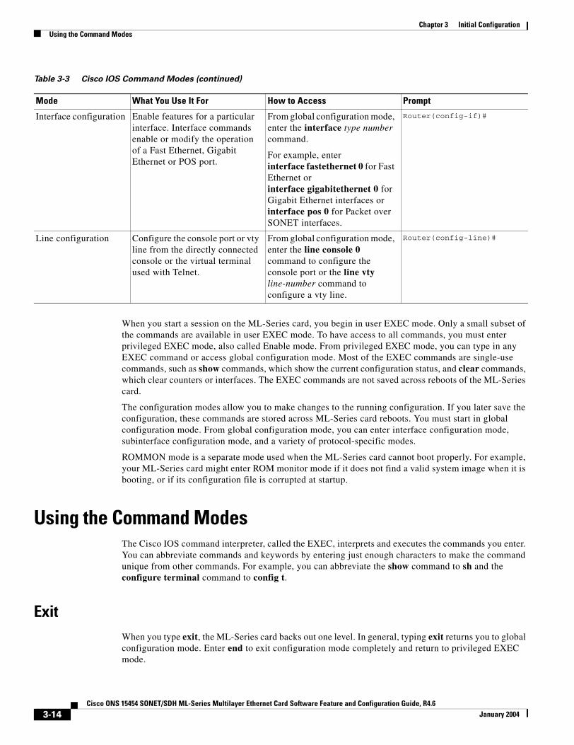
Chapter 3 Initial ConfigurationUsing the Command Modes
When you start a session on the ML-Series card, you begin in user EXEC mode. Only a small subset of the commands are available in user EXEC mode. To have access to all commands, you must enter privileged EXEC mode, also called Enable mode. From privileged EXEC mode, you can type in any EXEC command or access global configuration mode. Most of the EXEC commands are single-use commands, such as show commands, which show the current configuration status, and clear commands, which clear counters or interfaces. The EXEC commands are not saved across reboots of the ML-Series card.
The configuration modes allow you to make changes to the running configuration. If you later save the configuration, these commands are stored across ML-Series card reboots. You must start in global configuration mode. From global configuration mode, you can enter interface configuration mode, subinterface configuration mode, and a variety of protocol-specific modes.
ROMMON mode is a separate mode used when the ML-Series card cannot boot properly. For example, your ML-Series card might enter ROM monitor mode if it does not find a valid system image when it is booting, or if its configuration file is corrupted at startup.
Using the Command ModesThe Cisco IOS command interpreter, called the EXEC, interprets and executes the commands you enter. You can abbreviate commands and keywords by entering just enough characters to make the command unique from other commands. For example, you can abbreviate the show command to sh and the configure terminal command to config t.
ExitWhen you type exit, the ML-Series card backs out one level. In general, typing exit returns you to global configuration mode. Enter end to exit configuration mode completely and return to privileged EXEC mode.
Interface configuration Enable features for a particular interface. Interface commands enable or modify the operation of a Fast Ethernet, Gigabit Ethernet or POS port.
From global configuration mode, enter the interface type number command.
For example, enterinterface fastethernet 0 for Fast Ethernet or interface gigabitethernet 0 for Gigabit Ethernet interfaces orinterface pos 0 for Packet over SONET interfaces.
Router(config-if)#
Line configuration Configure the console port or vty line from the directly connected console or the virtual terminal used with Telnet.
From global configuration mode, enter the line console 0 command to configure the console port or the line vty line-number command to configure a vty line.
Router(config-line)#
Table 3-3 Cisco IOS Command Modes (continued)
Mode What You Use It For How to Access Prompt
3-14Cisco ONS 15454 SONET/SDH ML-Series Multilayer Ethernet Card Software Feature and Configuration Guide, R4.6
January 2004
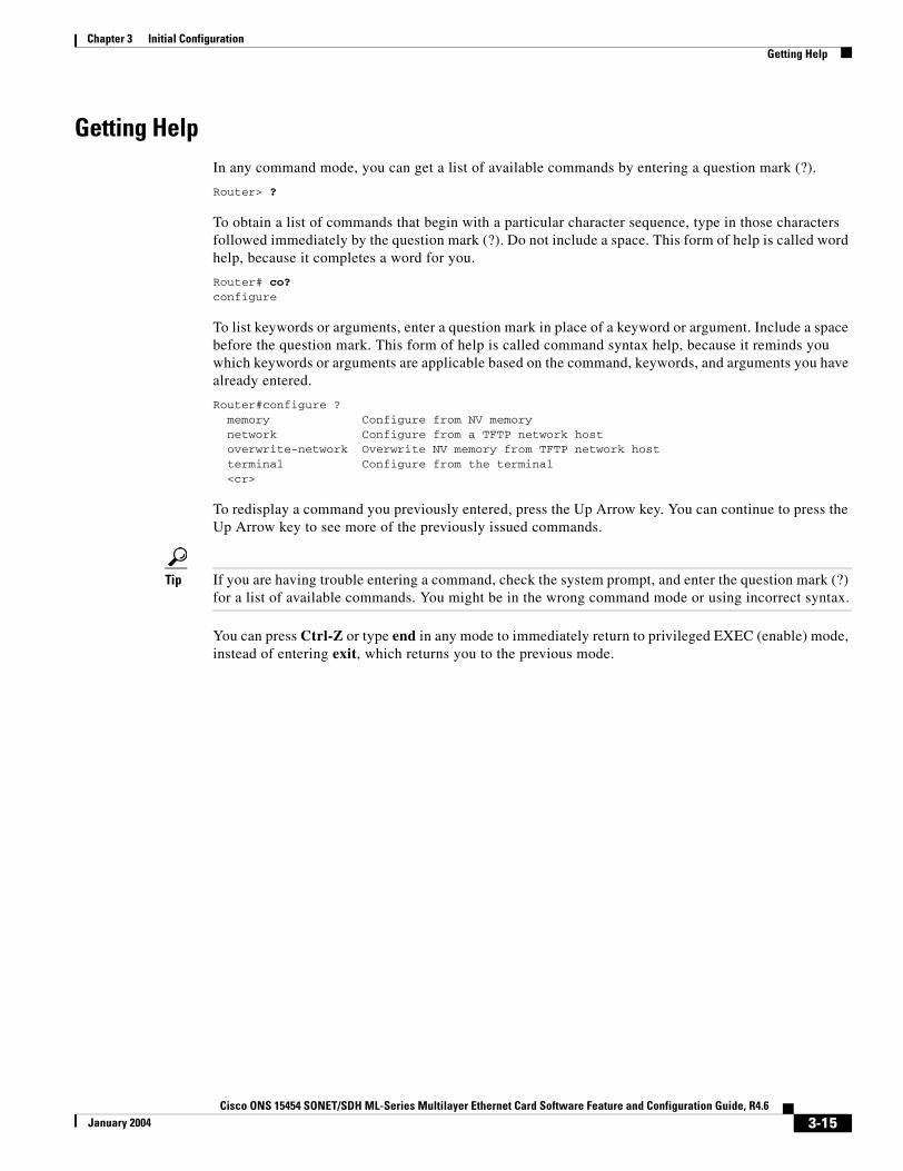
Chapter 3 Initial ConfigurationGetting Help
Getting HelpIn any command mode, you can get a list of available commands by entering a question mark (?).
Router> ?
To obtain a list of commands that begin with a particular character sequence, type in those characters followed immediately by the question mark (?). Do not include a space. This form of help is called word help, because it completes a word for you.
Router# co?configure
To list keywords or arguments, enter a question mark in place of a keyword or argument. Include a space before the question mark. This form of help is called command syntax help, because it reminds you which keywords or arguments are applicable based on the command, keywords, and arguments you have already entered.
Router#configure ? memory Configure from NV memory network Configure from a TFTP network host overwrite-network Overwrite NV memory from TFTP network host terminal Configure from the terminal <cr>
To redisplay a command you previously entered, press the Up Arrow key. You can continue to press the Up Arrow key to see more of the previously issued commands.
Tip If you are having trouble entering a command, check the system prompt, and enter the question mark (?) for a list of available commands. You might be in the wrong command mode or using incorrect syntax.
You can press Ctrl-Z or type end in any mode to immediately return to privileged EXEC (enable) mode, instead of entering exit, which returns you to the previous mode.
3-15Cisco ONS 15454 SONET/SDH ML-Series Multilayer Ethernet Card Software Feature and Configuration Guide, R4.6
January 2004

Chapter 3 Initial ConfigurationGetting Help
3-16Cisco ONS 15454 SONET/SDH ML-Series Multilayer Ethernet Card Software Feature and Configuration Guide, R4.6
January 2004
Cisco ONS 15454 SONET/SDH ML-Series Multilayer Ethernet Card SoftwarFebruary 2005
C H A P T E R 4
Configuring InterfacesThis chapter describes the basic interface configuration for the ML-Series card to help you get your ML-Series card up and running. For more information about the Cisco IOS commands used in this chapter, refer to the Cisco IOS Command Reference publication.
This chapter contains the following major sections:
• Interface Configuration, page 4-1
• Instructions for Configuring Interfaces, page 4-3
• Understanding Interfaces, page 4-4
• POS on the ML-Series Card, page 4-8
• Configuring the ML-Series POS Interfaces, page 4-12
• Common ML-Series POS Configurations, page 4-17
Note Complete the initial configuration of your ML-Series card before proceeding with configuring interfaces.
Interface ConfigurationThe main function of the ML-Series card is to relay packets from one data link to another. Consequently, you must configure the characteristics of the interfaces, which receive and send packets. Interface characteristics include, but are not limited to, IP address, address of the port, data encapsulation method, and media type.
Many features are enabled on a per-interface basis. Interface configuration mode contains commands that modify the interface operation (for example, of an Ethernet port). When you enter the interface command, you must specify the interface type and number.
The following general guidelines apply to all physical and virtual interface configuration processes:
• All interfaces have a name which is composed of an interface type (word) and a Port ID (number). For example, FastEthernet 2.
• Configure each interface with a bridge-group or IP address and IP subnet mask.
• VLANs are supported through the use of subinterfaces. The subinterface is a logical interface configured separately from the associated physical interface.
• Each physical interface, and the internal packet-over-SONET/SDH (POS) interfaces, have an assigned MAC address.
4-1e Feature and Configuration Guide, R4.6

Chapter 4 Configuring InterfacesMAC Addresses
MAC AddressesEvery port or device that connects to an Ethernet network needs a MAC address. Other devices in the network use MAC addresses to locate specific ports in the network and to create and update routing tables and data structures.
To find MAC addresses for a device, use the show interfaces command, as follows:
Router# sh interfaces fastEthernet 0FastEthernet0 is up, line protocol is up Hardware is epif_port, address is 0005.9a39.6634 (bia 0005.9a39.6634) MTU 1500 bytes, BW 100000 Kbit, DLY 100 usec, reliability 255/255, txload 1/255, rxload 1/255 Encapsulation ARPA, loopback not set Keepalive set (10 sec) Full-duplex, Auto Speed, 100BaseTX ARP type: ARPA, ARP Timeout 04:00:00 Last input 00:00:01, output 00:00:18, output hang never Last clearing of "show interface" counters never Input queue: 0/75/0/0 (size/max/drops/flushes); Total output drops: 0 Queueing strategy: fifo Output queue :0/40 (size/max) 5 minute input rate 0 bits/sec, 0 packets/sec 5 minute output rate 0 bits/sec, 0 packets/sec 11 packets input, 704 bytes Received 0 broadcasts, 0 runts, 0 giants, 0 throttles 0 input errors, 0 CRC, 0 frame, 0 overrun, 0 ignored 0 watchdog, 11 multicast 0 input packets with dribble condition detected 3 packets output, 1056 bytes, 0 underruns 0 output errors, 0 collisions, 0 interface resets 0 babbles, 0 late collision, 0 deferred 0 lost carrier, 0 no carrier 0 output buffer failures, 0 output buffers swapped out
Interface Port IDThe interface port ID designates the physical location of the interface within the ML-Series card. It is the name that you use to identify the interface you are configuring. The system software uses interface port IDs to control activity within the ML-Series card and to display status information. Interface port IDs are not used by other devices in the network; they are specific to the individual ML-Series card and its internal components and software.
The ML100T-12 port IDs for the 12 Fast Ethernet interfaces are Fast Ethernet 0 through 11. The ML1000-2 port IDs for the two Gigabit Ethernet interfaces are Gigabit Ethernet 0 and 1. Both ML-Series cards feature two POS ports, and the ML-Series port IDs for the two POS interfaces are POS 0 and 1. You can use user-defined abbreviations such as f0 through f11 to configure the 12 Fast Ethernet interfaces, gi0 or gi1 to configure the two Gigabit Ethernet interfaces, and POS0 and POS1 to configure the two POS ports.
You can use Cisco IOS show commands to display information about any or all the interfaces of the ML-Series card.
Caution Do not use the g0 or g1 for a Gigabit Ethernet user-defined abbreviation. This creates an unsupported group asynchronous interface.
4-2Cisco ONS 15454 SONET/SDH ML-Series Multilayer Ethernet Card Software Feature and Configuration Guide, R4.6
February 2005

Chapter 4 Configuring InterfacesInstructions for Configuring Interfaces
Instructions for Configuring InterfacesThe following general configuration instructions apply to all interfaces. Before you configure interfaces, develop a plan for a bridge or routed network.
To configure an interface, do the following:
Note Router or Switch is used as a generic prompt in documentation. Your specific prompt will vary.
Step 1 Enter the configure EXEC command at the privileged EXEC prompt to enter global configuration mode.
Router> enablePassword:Router# configure terminalRouter(config)#
Step 2 Enter the interface command, followed by the interface type (for example, fastethernet, gigabitethernet, or pos), and its interface port ID (see the “Interface Port ID” section on page 4-2).
For example, to configure a Gigabit Ethernet port, enter this command:
Router(config)# interface gigabitethernet number
Step 3 Follow each interface command with the interface configuration commands required for your particular interface.
The commands you enter define the protocols and applications that will run on the interface. The ML-Series card collects and applies commands to the interface command until you enter another interface command or a command that is not an interface configuration command. You can also enter end to return to privileged EXEC mode.
Step 4 Check the status of the configured interface by entering the EXEC show interface command.
Router# sh interface fastEthernet 0FastEthernet0 is up, line protocol is up Hardware is epif_port, address is 0005.9a39.6634 (bia 0005.9a39.6634) MTU 1500 bytes, BW 100000 Bit, DLY 100 use, reliability 255/255, txload 1/255, rxload 1/255 Encapsulation ARPA, loopback not set Keepalive set (10 sec) Full-duplex, Auto Speed, 100BaseTX ARP type: ARPA, ARP Timeout 04:00:00 Last input 00:00:01, output 00:00:18, output hang never Last clearing of "show interface" counters never Input queue: 0/75/0/0 (size/max/drops/flushes); Total output drops: 0 Queueing strategy: fifo Output queue :0/40 (size/max) 5 minute input rate 0 bits/sec, 0 packets/sec 5 minute output rate 0 bits/sec, 0 packets/sec 11 packets input, 704 bytes Received 0 broadcasts, 0 runts, 0 giants, 0 throttles 0 input errors, 0 CRC, 0 frame, 0 overrun, 0 ignored 0 watchdog, 11 multicast 0 input packets with dribble condition detected 3 packets output, 1056 bytes, 0 underruns 0 output errors, 0 collisions, 0 interface resets 0 babbles, 0 late collision, 0 deferred
4-3Cisco ONS 15454 SONET/SDH ML-Series Multilayer Ethernet Card Software Feature and Configuration Guide, R4.6
February 2005
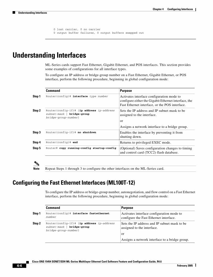
Chapter 4 Configuring InterfacesUnderstanding Interfaces
0 lost carrier, 0 no carrier 0 output buffer failures, 0 output buffers swapped out
Understanding InterfacesML-Series cards support Fast Ethernet, Gigabit Ethernet, and POS interfaces. This section provides some examples of configurations for all interface types.
To configure an IP address or bridge-group number on a Fast Ethernet, Gigabit Ethernet, or POS interface, perform the following procedure, beginning in global configuration mode:
Note Repeat Steps 1 through 3 to configure the other interfaces on the ML-Series card.
Configuring the Fast Ethernet Interfaces (ML100T-12)To configure the IP address or bridge-group number, autonegotiation, and flow control on a Fast Ethernet interface, perform the following procedure, beginning in global configuration mode:
Command Purpose
Step 1 Router(config)# interface type number Activates interface configuration mode to configure either the Gigabit Ethernet interface, the Fast Ethernet interface, or the POS interface.
Step 2 Router(config-if)# {ip address ip-address subnet-mask | bridge-group bridge-group-number}
Sets the IP address and IP subnet mask to be assigned to the interface.
or
Assigns a network interface to a bridge group.
Step 3 Router(config-if)# no shutdown Enables the interface by preventing it from shutting down.
Step 4 Router(config)# end Returns to privileged EXEC mode.
Step 5 Router# copy running-config startup-config (Optional) Saves configuration changes to timing and control card (TCC2) flash database.
Command Purpose
Step 1 Router(config)# interface fastethernet number
Activates interface configuration mode to configure the Fast Ethernet interface.
Step 2 Router(config-if)# {ip address ip-address subnet-mask | bridge-group bridge-group-number}
Sets the IP address and IP subnet mask to be assigned to the interface.
or
Assigns a network interface to a bridge group.
4-4Cisco ONS 15454 SONET/SDH ML-Series Multilayer Ethernet Card Software Feature and Configuration Guide, R4.6
February 2005

Chapter 4 Configuring InterfacesConfiguring the Gigabit Ethernet Interface (ML1000-2)
Example 4-1 shows how to do the initial configuration of a Fast Ethernet interface with an IP address, autonegotiated speed, and autonegotiated duplex.
Example 4-1 Initial Configuration of a Fast Ethernet Interface
Router(config)# interface fastethernet 1Router(config-if)# ip address 10.1.2.4 255.0.0.0Router(config-if)# speed autoRouter(config-if)# duplex autoRouter(config-if)# no shutdownRouter(config-if)# endRouter# copy running-config startup-config
Configuring the Gigabit Ethernet Interface (ML1000-2)To configure IP address or bridge-group number, autonegotiation, and flow control on a Gigabit Ethernet interface, perform the following procedure, beginning in global configuration mode:
Note The default setting for the negotiation mode is auto for the Gigabit Ethernet and Fast Ethernet interfaces. The Gigabit Ethernet port always operates at 1000 Mbps in full-duplex mode.
Step 3 Router(config-if)# [no] speed {10 | 100 | auto}
Configures the transmission speed for 10 or 100 Mbps. If you set the speed or duplex for auto, you enable autonegotiation on the system—the ML-Series card matches the speed and duplex mode of the partner node.
Step 4 Router(config-if)# [no] duplex {full | half | auto}
Sets full duplex, half duplex, or autonegotiate mode.
Step 5 Router(config-if)# flowcontrol send {on | off | desired}
(Optional) Sets the send flow control value for an interface. Flow control works only with port-level policing.
Step 6 Router(config-if)# no shutdown Enables the interface by preventing it from shutting down.
Step 7 Router(config)# end Returns to privileged EXEC mode.
Step 8 Router# copy running-config startup-config (Optional) Saves your configuration changes to TCC2 flash database.
Command Purpose
Command Purpose
Step 1 Router# interface gigabitethernet number Activates interface configuration mode to configure the Gigabit Ethernet interface.
Step 2 Router(config-if)# {ip address ip-address subnet-mask | bridge-group bridge-group-number}
Sets the IP address and subnet mask.
or
Assigns a network interface to a bridge group.
4-5Cisco ONS 15454 SONET/SDH ML-Series Multilayer Ethernet Card Software Feature and Configuration Guide, R4.6
February 2005
Chapter 4 Configuring InterfacesMonitoring Operations on the Fast Ethernet and Gigabit Ethernet Interfaces
Note Repeat Steps 1 to 4 to configure the other Gigabit Ethernet interfaces.
Example 4-2 shows how to do an initial configuration of a Gigabit Ethernet interface with autonegotiation and an IP address.
Example 4-2 Initial Configuration of a Gigabit Ethernet Interface
Router(config)# interface gigabitethernet 0Router(config-if)# ip address 10.1.2.3 255.0.0.0Router(config-if)# negotiation autoRouter(config-if)# no shutdownRouter(config-if)# endRouter# copy running-config startup-config
Monitoring Operations on the Fast Ethernet and Gigabit Ethernet InterfacesTo verify the settings after you have configured Fast Ethernet interfaces, enter the show interface command.
Example 4-3 shows the output from the show interface command, which displays the status of the Fast Ethernet interface including port speed and duplex operation.
Example 4-3 show interface Command Output
Router# show interface fastEthernet 0FastEthernet0 is up, line protocol is up Hardware is epif_port, address is 0005.9a39.6634 (bia 0005.9a39.6634) MTU 1500 bytes, BW 100000 Kbit, DLY 100 usec, reliability 255/255, txload 1/255, rxload 1/255 Encapsulation ARPA, loopback not set Keepalive set (10 sec) Full-duplex, 100Mb/s, 100BaseTX ARP type: ARPA, ARP Timeout 04:00:00 Last input never, output 00:00:23, output hang never
Step 3 Router(config-if)# [no] negotiation auto Sets negotiation mode to auto. The Gigabit Ethernet port attempts to negotiate the link with the partner port.
If you want the port to force the link up no matter what the partner port setting is, set the Gigabit Ethernet interface to no negotiation auto.
Step 4 Router(config-if)# flowcontrol {send | receive} {on | off | desired}
(Optional) Sets the send or receive flow control value for an interface. Flow control works only with port-level policing.
Step 5 Router(config-if)# no shutdown Enables the interface by preventing it from shutting down.
Step 6 Router(config)# end Returns to privileged EXEC mode.
Step 7 Router# copy running-config startup-config (Optional) Saves configuration changes to TCC2 flash database.
Command Purpose
4-6Cisco ONS 15454 SONET/SDH ML-Series Multilayer Ethernet Card Software Feature and Configuration Guide, R4.6
February 2005

Chapter 4 Configuring InterfacesMonitoring Operations on the Fast Ethernet and Gigabit Ethernet Interfaces
Last clearing of "show interface" counters never Input queue: 0/75/0/0 (size/max/drops/flushes); Total output drops: 0 Queueing strategy: fifo Output queue: 0/40 (size/max) 5 minute input rate 0 bits/sec, 0 packets/sec 5 minute output rate 0 bits/sec, 0 packets/sec 0 packets input, 0 bytes Received 0 broadcasts (0 IP multicast) 0 runts, 0 giants, 0 throttles 0 input errors, 0 CRC, 0 frame, 0 overrun, 0 ignored 0 watchdog, 0 multicast 0 input packets with dribble condition detected 4 packets output, 1488 bytes, 0 underruns 0 output errors, 0 collisions, 0 interface resets 0 babbles, 0 late collision, 0 deferred 0 lost carrier, 0 no carrier 0 output buffer failures, 0 output buffers swapped out
Enter the show controller command to display information about the Fast Ethernet controller chip.
Example 4-4 shows the output from the show controller command, which shows statistics, including information about initialization block information, transmit ring, receive ring, and errors.
Example 4-4 show controller Command Output
Router# show controller fastEthernet 0IF Name: FastEthernet0 Port Status DOWNSend Flow Control : Disabled Receive Flow Control : EnabledMAC registersCMCR : 0x0000042D (Tx Enabled, Rx Disabled)CMPR : 0x150B0A80 (Long Frame Disabled)FCR : 0x0000A00B (Rx Pause detection Enabled)MII registers:Control Register (0x0): 0x4000 (Auto negotiation disabled)Status Register (0x1): 0x7809 (Link status Down)PHY Identification Register 1 (0x2): 0x40 PHY Identification Register 2 (0x3): 0x61D4Auto Neg. Advertisement Reg (0x4): 0x1E1 (Speed 100, Duplex Full)Auto Neg. Partner Ability Reg (0x5): 0x0 (Speed 10, Duplex Half)Auto Neg. Expansion Register (0x6): 0x4 100Base-X Aux Control Reg (0x10): 0x2000100Base-X Aux Status Register(0x11): 0x0 100Base-X Rcv Error Counter (0x12): 0x0 100Base-X False Carr. Counter(0x13): 0x0
Enter the show run interfaces fastEthernet 0 command to display information about the configuration of the Fast Ethernet interface. The command is useful when there are multiple interfaces and you want to look at the configuration of a specific interface.
Example 4-5 shows output from the show controller command, which includes information about the IP or lack of IP address and the state of the interface.
Example 4-5 show controller Command Output
daytona# show run interface fastEthernet 0Building configuration...
Current configuration : 56 bytes!interface FastEthernet0
4-7Cisco ONS 15454 SONET/SDH ML-Series Multilayer Ethernet Card Software Feature and Configuration Guide, R4.6
February 2005
Chapter 4 Configuring InterfacesPOS on the ML-Series Card
no ip addressshutdown
end
POS on the ML-Series CardPacket over SONET/SDH (POS) is a high-speed method of transporting IP traffic between two points. This technology combines the Point-to-Point Protocol (PPP) with SONET and SDH interfaces. SONET is an octet-synchronous multiplex scheme defined by the ANSI standard (T1.105.1988) for optical digital transmission, and SDH is the ETS) equivalent.
ML-Series SONET/SDH Transmission RatesSONET transmission rates are integral multiples of 51.840 Mbps. Table 4-1 shows supported transmission multiples.
SONET Frame FundamentalsSONET is a Layer 1 protocol that uses a layered architecture. Figure 4-1 shows SONET’s three layers: section, line, and path. The section overhead (SOH) and line overhead (LOH) form the transport overhead (TOH), while the path overhead (POH) and actual payload (referred to as payload capacity) form the synchronous payload envelope (SPE). Each layer adds a number of overhead bytes to the SONET frame.
Table 4-1 Transmission Multiples Supported by ML-Series Cards
Topology Supported Sizes
Circuits terminated by two ML-Series cards STS-1, STS-3c, STS-6c, STS-9c, STS-12c, and STS-24c (SONET) or VC4, VC4-2c, VC4-3c, VC4-4c, and VC4-8c (SDH)
Circuits terminated by G-Series card and ML-Series card
STS-1, STS-3c, STS-6c, STS-9c, and STS-12c (SONET) or VC4, VC4-2c, VC4-3c, VC4-4c, and VC4-8c (SDH)
Circuits terminated by ML-Series card and External POS device
STS-3c and STS-12c (SONET) or VC4 and VC4-4c (SDH)
4-8Cisco ONS 15454 SONET/SDH ML-Series Multilayer Ethernet Card Software Feature and Configuration Guide, R4.6
February 2005
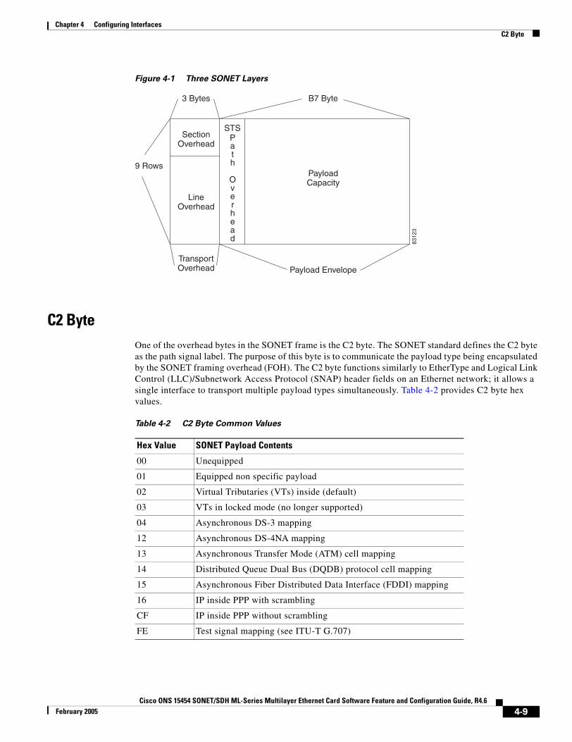
Chapter 4 Configuring InterfacesC2 Byte
Figure 4-1 Three SONET Layers
C2 ByteOne of the overhead bytes in the SONET frame is the C2 byte. The SONET standard defines the C2 byte as the path signal label. The purpose of this byte is to communicate the payload type being encapsulated by the SONET framing overhead (FOH). The C2 byte functions similarly to EtherType and Logical Link Control (LLC)/Subnetwork Access Protocol (SNAP) header fields on an Ethernet network; it allows a single interface to transport multiple payload types simultaneously. Table 4-2 provides C2 byte hex values.
B7 Byte3 Bytes
9 Rows
SectionOverhead
LineOverhead
STS
TransportOverhead Payload Envelope
PayloadCapacity
8312
3
Path Overhead
Table 4-2 C2 Byte Common Values
Hex Value SONET Payload Contents
00 Unequipped
01 Equipped non specific payload
02 Virtual Tributaries (VTs) inside (default)
03 VTs in locked mode (no longer supported)
04 Asynchronous DS-3 mapping
12 Asynchronous DS-4NA mapping
13 Asynchronous Transfer Mode (ATM) cell mapping
14 Distributed Queue Dual Bus (DQDB) protocol cell mapping
15 Asynchronous Fiber Distributed Data Interface (FDDI) mapping
16 IP inside PPP with scrambling
CF IP inside PPP without scrambling
FE Test signal mapping (see ITU-T G.707)
4-9Cisco ONS 15454 SONET/SDH ML-Series Multilayer Ethernet Card Software Feature and Configuration Guide, R4.6
February 2005
Chapter 4 Configuring InterfacesC2 Byte
C2 Byte and Scrambling
As listed in Table 4-2, POS interfaces use a value of 0x16 or 0xCF in the C2 byte depending on whether ATM-style scrambling is enabled or not. RFC 2615, which defines PPP over SONET, mandates the use of these values based on the scrambling setting. The RFC defines the C2 byte values as follows: “the value of 22 (16 hex) is used to indicate PPP with X^43+ 1 scrambling [4]. For compatibility with RFC 1619 (STS-3c-SPE/VC-4 only), if scrambling has been configured to be off, then the value 207 (CF hex) is used for the Path Signal Label to indicate PPP without scrambling.”
In other words:
• If scrambling is enabled, POS interfaces use a C2 value of 0x16 (PPP and high-level data link control [HDLC] encapsulation).
• If scrambling is disabled, POS interfaces use a C2 value of 0xCF (PPP and HDLC encapsulation).
• LEX encapsulation uses a C2 value of 0x01 regardless of the scrambling setting.
Most POS interfaces that use a default C2 value of 0x16 (22 decimal) insert the pos flag c2 22 command in the configuration, although this line does not appear in the running configuration since it is the default. Use the pos flag c2 command to change the value from its default, as shown in Example 4-6.
Example 4-6 pos fag c2 Command
Router(config-if)# pos flag c2 ? <0-255> byte value, default 0x16
Note Changing the C2 value from the default value does not affect POS scrambling settings.
Use the show run command to confirm your change. The show controller pos command (Example 4-7) outputs the receive and transmit values and the C2 value. Thus, changing the value on the local end does not change the value in the show controller command output.
Example 4-7 show controller pos Command
Router# sh controllers pos 0Interface POS0Hardware is Packet/Ethernet over SonetPATH PAIS = 0 PLOP = 0 PRDI = 0 PTIM = 0 PPLM = 0 PUNEQ = 0 PPDI = 0 BER_SF_B3 = 0 BER_SD_B3 = 0 BIP(B3) = 14 REI = 155 NEWPTR = 0 PSE = 0 NSE = 0
Active Alarms : NoneDemoted Alarms: NoneActive Defects: NoneAlarms reportable to TCC/CLI: PAIS PRDI PLOP PUNEQ PPLM PTIM PPDI BER_SF_B3 BER_SD_B3Link state change defects: PAIS PLOP PRDI PPDI BER_SF_B3Link state change time : 200 (msec)
DOS FPGA channel number: 0Starting STS (0 based) : 0Circuit size : STS-24cRDI Mode : 1 bitC2 (tx / rx) : 0x01 / 0x01Framing : SONET
4-10Cisco ONS 15454 SONET/SDH ML-Series Multilayer Ethernet Card Software Feature and Configuration Guide, R4.6
February 2005
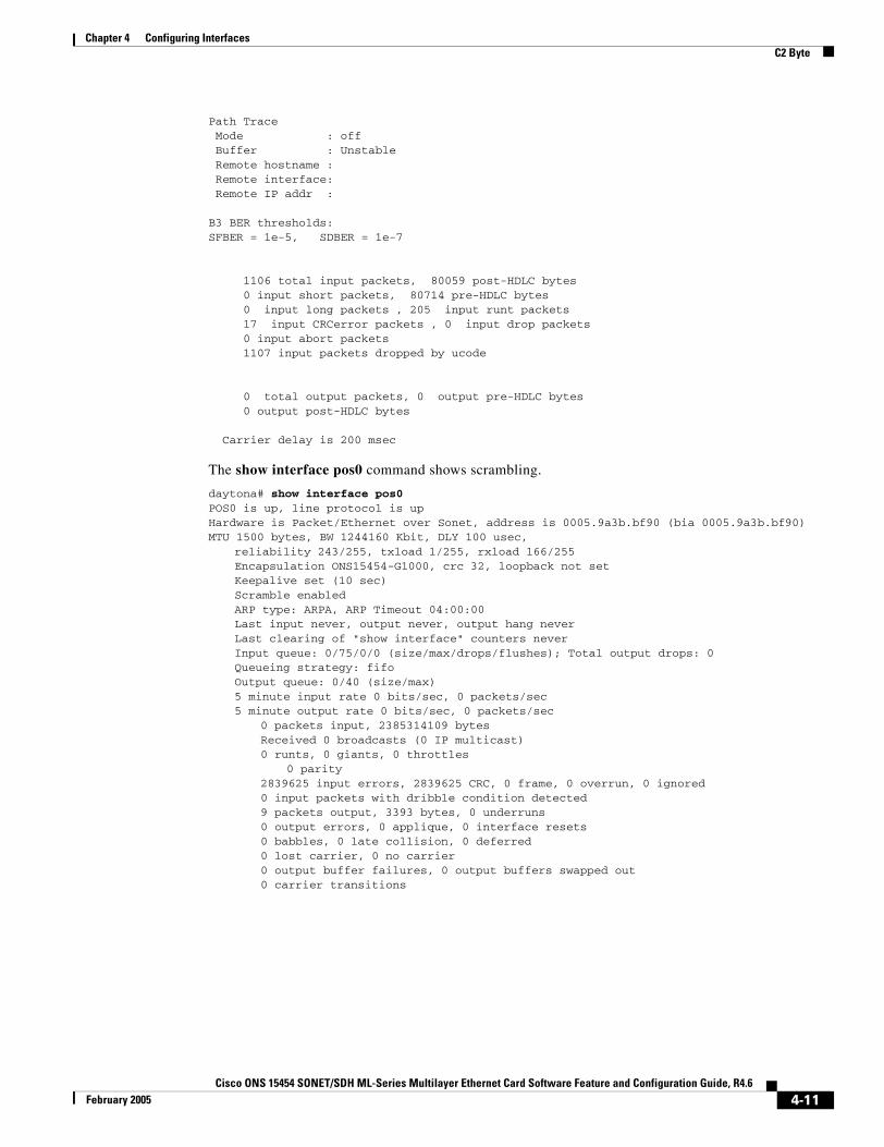
Chapter 4 Configuring InterfacesC2 Byte
Path Trace Mode : off Buffer : Unstable Remote hostname : Remote interface: Remote IP addr :
B3 BER thresholds:SFBER = 1e-5, SDBER = 1e-7
1106 total input packets, 80059 post-HDLC bytes 0 input short packets, 80714 pre-HDLC bytes 0 input long packets , 205 input runt packets 17 input CRCerror packets , 0 input drop packets 0 input abort packets 1107 input packets dropped by ucode
0 total output packets, 0 output pre-HDLC bytes 0 output post-HDLC bytes
Carrier delay is 200 msec
The show interface pos0 command shows scrambling.
daytona# show interface pos0POS0 is up, line protocol is up Hardware is Packet/Ethernet over Sonet, address is 0005.9a3b.bf90 (bia 0005.9a3b.bf90)MTU 1500 bytes, BW 1244160 Kbit, DLY 100 usec,
reliability 243/255, txload 1/255, rxload 166/255Encapsulation ONS15454-G1000, crc 32, loopback not setKeepalive set (10 sec)Scramble enabled ARP type: ARPA, ARP Timeout 04:00:00Last input never, output never, output hang neverLast clearing of "show interface" counters neverInput queue: 0/75/0/0 (size/max/drops/flushes); Total output drops: 0Queueing strategy: fifoOutput queue: 0/40 (size/max)5 minute input rate 0 bits/sec, 0 packets/sec5 minute output rate 0 bits/sec, 0 packets/sec
0 packets input, 2385314109 bytesReceived 0 broadcasts (0 IP multicast)0 runts, 0 giants, 0 throttles
0 parity2839625 input errors, 2839625 CRC, 0 frame, 0 overrun, 0 ignored0 input packets with dribble condition detected9 packets output, 3393 bytes, 0 underruns0 output errors, 0 applique, 0 interface resets0 babbles, 0 late collision, 0 deferred0 lost carrier, 0 no carrier0 output buffer failures, 0 output buffers swapped out0 carrier transitions
4-11Cisco ONS 15454 SONET/SDH ML-Series Multilayer Ethernet Card Software Feature and Configuration Guide, R4.6
February 2005
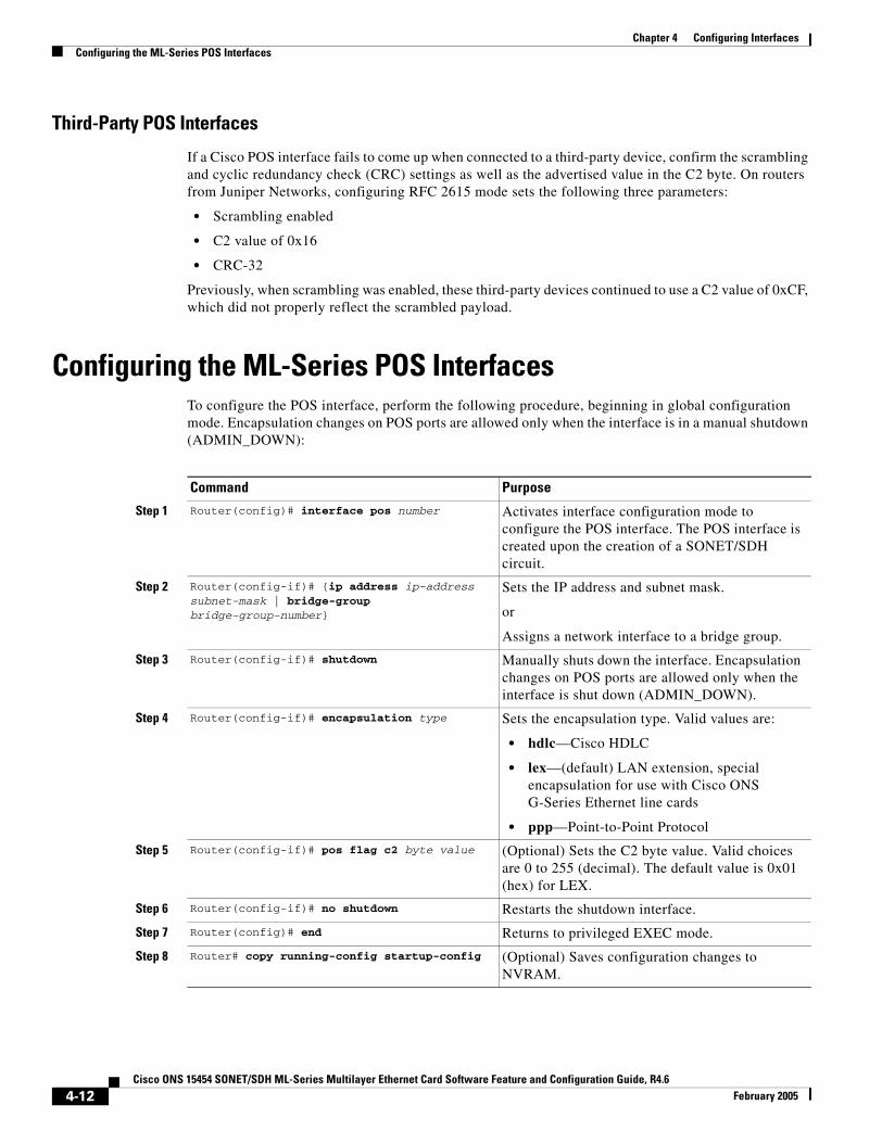
Chapter 4 Configuring InterfacesConfiguring the ML-Series POS Interfaces
Third-Party POS Interfaces
If a Cisco POS interface fails to come up when connected to a third-party device, confirm the scrambling and cyclic redundancy check (CRC) settings as well as the advertised value in the C2 byte. On routers from Juniper Networks, configuring RFC 2615 mode sets the following three parameters:
• Scrambling enabled
• C2 value of 0x16
• CRC-32
Previously, when scrambling was enabled, these third-party devices continued to use a C2 value of 0xCF, which did not properly reflect the scrambled payload.
Configuring the ML-Series POS InterfacesTo configure the POS interface, perform the following procedure, beginning in global configuration mode. Encapsulation changes on POS ports are allowed only when the interface is in a manual shutdown (ADMIN_DOWN):
Command Purpose
Step 1 Router(config)# interface pos number Activates interface configuration mode to configure the POS interface. The POS interface is created upon the creation of a SONET/SDH circuit.
Step 2 Router(config-if)# {ip address ip-address subnet-mask | bridge-group bridge-group-number}
Sets the IP address and subnet mask.
or
Assigns a network interface to a bridge group.
Step 3 Router(config-if)# shutdown Manually shuts down the interface. Encapsulation changes on POS ports are allowed only when the interface is shut down (ADMIN_DOWN).
Step 4 Router(config-if)# encapsulation type Sets the encapsulation type. Valid values are:
• hdlc—Cisco HDLC
• lex—(default) LAN extension, special encapsulation for use with Cisco ONS G-Series Ethernet line cards
• ppp—Point-to-Point Protocol
Step 5 Router(config-if)# pos flag c2 byte value (Optional) Sets the C2 byte value. Valid choices are 0 to 255 (decimal). The default value is 0x01 (hex) for LEX.
Step 6 Router(config-if)# no shutdown Restarts the shutdown interface.
Step 7 Router(config)# end Returns to privileged EXEC mode.
Step 8 Router# copy running-config startup-config (Optional) Saves configuration changes to NVRAM.
4-12Cisco ONS 15454 SONET/SDH ML-Series Multilayer Ethernet Card Software Feature and Configuration Guide, R4.6
February 2005
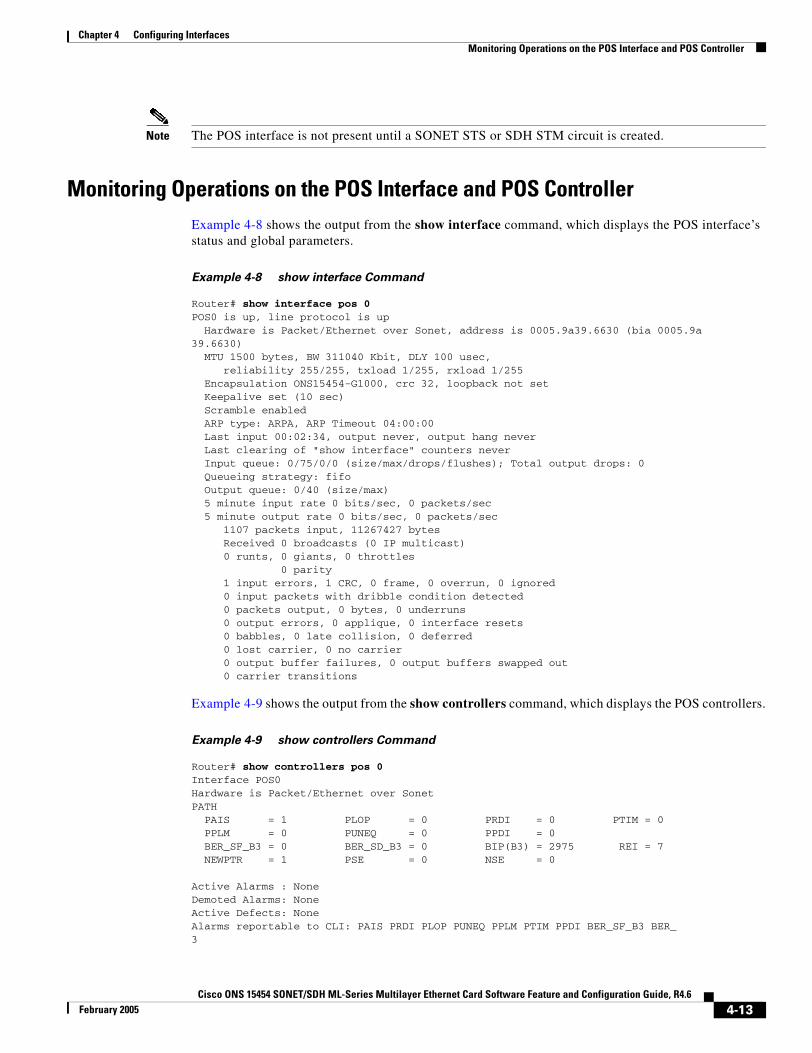
Chapter 4 Configuring InterfacesMonitoring Operations on the POS Interface and POS Controller
Note The POS interface is not present until a SONET STS or SDH STM circuit is created.
Monitoring Operations on the POS Interface and POS ControllerExample 4-8 shows the output from the show interface command, which displays the POS interface’s status and global parameters.
Example 4-8 show interface Command
Router# show interface pos 0POS0 is up, line protocol is up Hardware is Packet/Ethernet over Sonet, address is 0005.9a39.6630 (bia 0005.9a39.6630) MTU 1500 bytes, BW 311040 Kbit, DLY 100 usec, reliability 255/255, txload 1/255, rxload 1/255 Encapsulation ONS15454-G1000, crc 32, loopback not set Keepalive set (10 sec) Scramble enabled ARP type: ARPA, ARP Timeout 04:00:00 Last input 00:02:34, output never, output hang never Last clearing of "show interface" counters never Input queue: 0/75/0/0 (size/max/drops/flushes); Total output drops: 0 Queueing strategy: fifo Output queue: 0/40 (size/max) 5 minute input rate 0 bits/sec, 0 packets/sec 5 minute output rate 0 bits/sec, 0 packets/sec 1107 packets input, 11267427 bytes Received 0 broadcasts (0 IP multicast) 0 runts, 0 giants, 0 throttles 0 parity 1 input errors, 1 CRC, 0 frame, 0 overrun, 0 ignored 0 input packets with dribble condition detected 0 packets output, 0 bytes, 0 underruns 0 output errors, 0 applique, 0 interface resets 0 babbles, 0 late collision, 0 deferred 0 lost carrier, 0 no carrier 0 output buffer failures, 0 output buffers swapped out 0 carrier transitions
Example 4-9 shows the output from the show controllers command, which displays the POS controllers.
Example 4-9 show controllers Command
Router# show controllers pos 0Interface POS0Hardware is Packet/Ethernet over SonetPATH PAIS = 1 PLOP = 0 PRDI = 0 PTIM = 0 PPLM = 0 PUNEQ = 0 PPDI = 0 BER_SF_B3 = 0 BER_SD_B3 = 0 BIP(B3) = 2975 REI = 7 NEWPTR = 1 PSE = 0 NSE = 0
Active Alarms : NoneDemoted Alarms: NoneActive Defects: NoneAlarms reportable to CLI: PAIS PRDI PLOP PUNEQ PPLM PTIM PPDI BER_SF_B3 BER_3
4-13Cisco ONS 15454 SONET/SDH ML-Series Multilayer Ethernet Card Software Feature and Configuration Guide, R4.6
February 2005
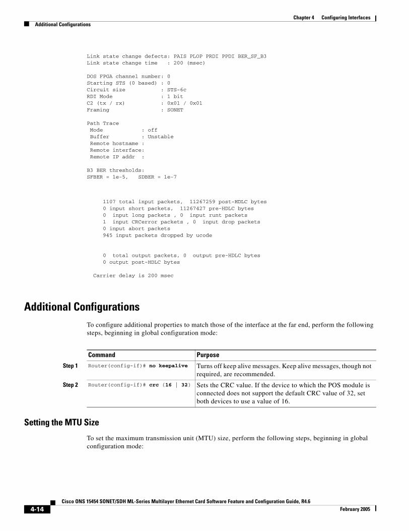
Chapter 4 Configuring InterfacesAdditional Configurations
Link state change defects: PAIS PLOP PRDI PPDI BER_SF_B3Link state change time : 200 (msec)
DOS FPGA channel number: 0Starting STS (0 based) : 0Circuit size : STS-6cRDI Mode : 1 bitC2 (tx / rx) : 0x01 / 0x01Framing : SONET
Path Trace Mode : off Buffer : Unstable Remote hostname : Remote interface: Remote IP addr :
B3 BER thresholds:SFBER = 1e-5, SDBER = 1e-7
1107 total input packets, 11267259 post-HDLC bytes 0 input short packets, 11267427 pre-HDLC bytes 0 input long packets , 0 input runt packets 1 input CRCerror packets , 0 input drop packets 0 input abort packets 945 input packets dropped by ucode
0 total output packets, 0 output pre-HDLC bytes 0 output post-HDLC bytes
Carrier delay is 200 msec
Additional ConfigurationsTo configure additional properties to match those of the interface at the far end, perform the following steps, beginning in global configuration mode:
Setting the MTU Size
To set the maximum transmission unit (MTU) size, perform the following steps, beginning in global configuration mode:
Command Purpose
Step 1 Router(config-if)# no keepalive Turns off keep alive messages. Keep alive messages, though not required, are recommended.
Step 2 Router(config-if)# crc {16 | 32} Sets the CRC value. If the device to which the POS module is connected does not support the default CRC value of 32, set both devices to use a value of 16.
4-14Cisco ONS 15454 SONET/SDH ML-Series Multilayer Ethernet Card Software Feature and Configuration Guide, R4.6
February 2005
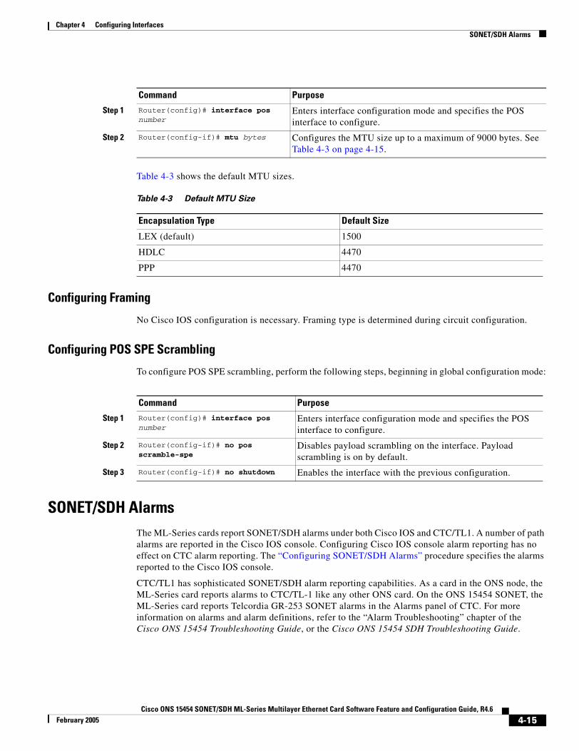
Chapter 4 Configuring InterfacesSONET/SDH Alarms
Table 4-3 shows the default MTU sizes.
Configuring Framing
No Cisco IOS configuration is necessary. Framing type is determined during circuit configuration.
Configuring POS SPE Scrambling
To configure POS SPE scrambling, perform the following steps, beginning in global configuration mode:
SONET/SDH AlarmsThe ML-Series cards report SONET/SDH alarms under both Cisco IOS and CTC/TL1. A number of path alarms are reported in the Cisco IOS console. Configuring Cisco IOS console alarm reporting has no effect on CTC alarm reporting. The “Configuring SONET/SDH Alarms” procedure specifies the alarms reported to the Cisco IOS console.
CTC/TL1 has sophisticated SONET/SDH alarm reporting capabilities. As a card in the ONS node, the ML-Series card reports alarms to CTC/TL-1 like any other ONS card. On the ONS 15454 SONET, the ML-Series card reports Telcordia GR-253 SONET alarms in the Alarms panel of CTC. For more information on alarms and alarm definitions, refer to the “Alarm Troubleshooting” chapter of the Cisco ONS 15454 Troubleshooting Guide, or the Cisco ONS 15454 SDH Troubleshooting Guide.
Command Purpose
Step 1 Router(config)# interface pos number
Enters interface configuration mode and specifies the POS interface to configure.
Step 2 Router(config-if)# mtu bytes Configures the MTU size up to a maximum of 9000 bytes. See Table 4-3 on page 4-15.
Table 4-3 Default MTU Size
Encapsulation Type Default Size
LEX (default) 1500
HDLC 4470
PPP 4470
Command Purpose
Step 1 Router(config)# interface pos number
Enters interface configuration mode and specifies the POS interface to configure.
Step 2 Router(config-if)# no pos scramble-spe
Disables payload scrambling on the interface. Payload scrambling is on by default.
Step 3 Router(config-if)# no shutdown Enables the interface with the previous configuration.
4-15Cisco ONS 15454 SONET/SDH ML-Series Multilayer Ethernet Card Software Feature and Configuration Guide, R4.6
February 2005
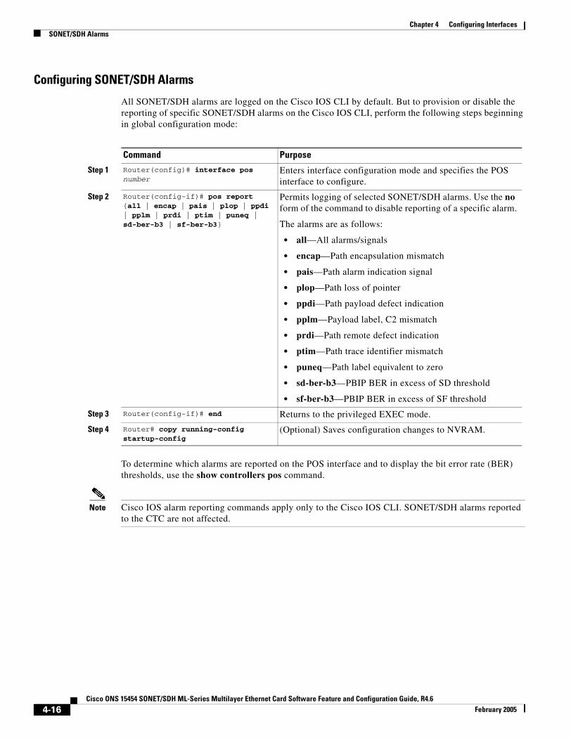
Chapter 4 Configuring InterfacesSONET/SDH Alarms
Configuring SONET/SDH Alarms
All SONET/SDH alarms are logged on the Cisco IOS CLI by default. But to provision or disable the reporting of specific SONET/SDH alarms on the Cisco IOS CLI, perform the following steps beginning in global configuration mode:
To determine which alarms are reported on the POS interface and to display the bit error rate (BER) thresholds, use the show controllers pos command.
Note Cisco IOS alarm reporting commands apply only to the Cisco IOS CLI. SONET/SDH alarms reported to the CTC are not affected.
Command Purpose
Step 1 Router(config)# interface pos number
Enters interface configuration mode and specifies the POS interface to configure.
Step 2 Router(config-if)# pos report {all | encap | pais | plop | ppdi | pplm | prdi | ptim | puneq | sd-ber-b3 | sf-ber-b3}
Permits logging of selected SONET/SDH alarms. Use the no form of the command to disable reporting of a specific alarm.
The alarms are as follows:
• all—All alarms/signals
• encap—Path encapsulation mismatch
• pais—Path alarm indication signal
• plop—Path loss of pointer
• ppdi—Path payload defect indication
• pplm—Payload label, C2 mismatch
• prdi—Path remote defect indication
• ptim—Path trace identifier mismatch
• puneq—Path label equivalent to zero
• sd-ber-b3—PBIP BER in excess of SD threshold
• sf-ber-b3—PBIP BER in excess of SF threshold
Step 3 Router(config-if)# end Returns to the privileged EXEC mode.
Step 4 Router# copy running-config startup-config
(Optional) Saves configuration changes to NVRAM.
4-16Cisco ONS 15454 SONET/SDH ML-Series Multilayer Ethernet Card Software Feature and Configuration Guide, R4.6
February 2005
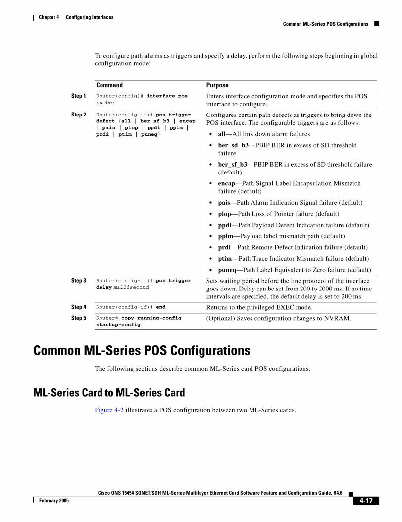
Chapter 4 Configuring InterfacesCommon ML-Series POS Configurations
To configure path alarms as triggers and specify a delay, perform the following steps beginning in global configuration mode:
Common ML-Series POS ConfigurationsThe following sections describe common ML-Series card POS configurations.
ML-Series Card to ML-Series CardFigure 4-2 illustrates a POS configuration between two ML-Series cards.
Command Purpose
Step 1 Router(config)# interface pos number
Enters interface configuration mode and specifies the POS interface to configure.
Step 2 Router(config-if)# pos trigger defect {all | ber_sf_b3 | encap | pais | plop | ppdi | pplm | prdi | ptim | puneq}
Configures certain path defects as triggers to bring down the POS interface. The configurable triggers are as follows:
• all—All link down alarm failures
• ber_sd_b3—PBIP BER in excess of SD threshold failure
• ber_sf_b3—PBIP BER in excess of SD threshold failure (default)
• encap—Path Signal Label Encapsulation Mismatch failure (default)
• pais—Path Alarm Indication Signal failure (default)
• plop—Path Loss of Pointer failure (default)
• ppdi—Path Payload Defect Indication failure (default)
• pplm—Payload label mismatch path (default)
• prdi—Path Remote Defect Indication failure (default)
• ptim—Path Trace Indicator Mismatch failure (default)
• puneq—Path Label Equivalent to Zero failure (default)
Step 3 Router(config-if)# pos trigger delay millisecond
Sets waiting period before the line protocol of the interface goes down. Delay can be set from 200 to 2000 ms. If no time intervals are specified, the default delay is set to 200 ms.
Step 4 Router(config-if)# end Returns to the privileged EXEC mode.
Step 5 Router# copy running-config startup-config
(Optional) Saves configuration changes to NVRAM.
4-17Cisco ONS 15454 SONET/SDH ML-Series Multilayer Ethernet Card Software Feature and Configuration Guide, R4.6
February 2005

Chapter 4 Configuring InterfacesML-Series Card to Cisco 12000 GSR-Series Router
Figure 4-2 ML-Series Card to ML-Series Card POS Configuration
Example 4-10 shows the code associated with the configuration of Router A.
Example 4-10 Router A Configuration
hostname Router_A!interface FastEthernet0 ip address 192.168.1.1 255.255.255.0!interface POS0 ip address 192.168.2.1 255.255.255.0 crc 32pos flag c2 1!router ospf 1 log-adjacency-changes network 192.168.1.0 0.0.0.255 area 0 network 192.168.2.0 0.0.0.255 area 0
Example 4-11shows the code associated with the configuration of Router B.
Example 4-11 Router B Configuration
hostname Router_B!interface FastEthernet0 ip address 192.168.3.1 255.255.255.0!interface POS0 ip address 192.168.2.2 255.255.255.0 crc 32pos flag c2 1!router ospf 1 log-adjacency-changes network 192.168.2.0 0.0.0.255 area 0 network 192.168.3.0 0.0.0.255 area 0!
ML-Series Card to Cisco 12000 GSR-Series RouterFigure 4-3 illustrates a POS configuration between an ML-Series card and a Cisco 12000 GSR-Series router.
ONS 15454with ML100T-12
fast ethernet 0
pos 0pos 0
fast ethernet 0
ML_Series_A
SONET/SDH
192.168.1.1
192.168.2.1 192.168.2.2
192.168.3.1
ONS 15454with ML100T-12
ML_Series_B
8312
7
4-18Cisco ONS 15454 SONET/SDH ML-Series Multilayer Ethernet Card Software Feature and Configuration Guide, R4.6
February 2005
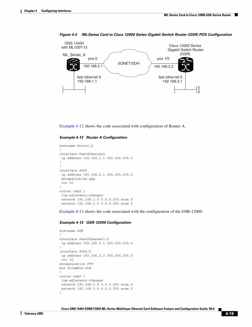
Chapter 4 Configuring InterfacesML-Series Card to Cisco 12000 GSR-Series Router
Figure 4-3 ML-Series Card to Cisco 12000 Series Gigabit Switch Router (GSR) POS Configuration
Example 4-12 shows the code associated with configuration of Router A.
Example 4-12 Router A Configuration
hostname Router_A!interface FastEthernet0 ip address 192.168.1.1 255.255.255.0!!interface POS0 ip address 192.168.2.1 255.255.255.0 encapsulation ppp crc 32!router ospf 1 log-adjacency-changes network 192.168.1.0 0.0.0.255 area 0 network 192.168.2.0 0.0.0.255 area 0
Example 4-13 shows the code associated with the configuration of the GSR-12000.
Example 4-13 GSR-12000 Configuration
hostname GSR!interface FastEthernet1/0 ip address 192.168.3.1 255.255.255.0!interface POS2/0 ip address 192.168.2.2 255.255.255.0 crc 32encapsulation PPPpos scramble-atm!router ospf 1 log-adjacency-changes network 192.168.2.0 0.0.0.255 area 0 network 192.168.3.0 0.0.0.255 area 0!
ONS 15454with ML100T-12
fast ethernet 0
pos 1/0pos 0
fast ethernet 0
ML_Series_A
SONET/SDH
192.168.1.1
192.168.2.1 192.168.2.2
192.168.3.1
Cisco 12000 Series Gigabit Switch Router
(GSR)
8312
6
4-19Cisco ONS 15454 SONET/SDH ML-Series Multilayer Ethernet Card Software Feature and Configuration Guide, R4.6
February 2005
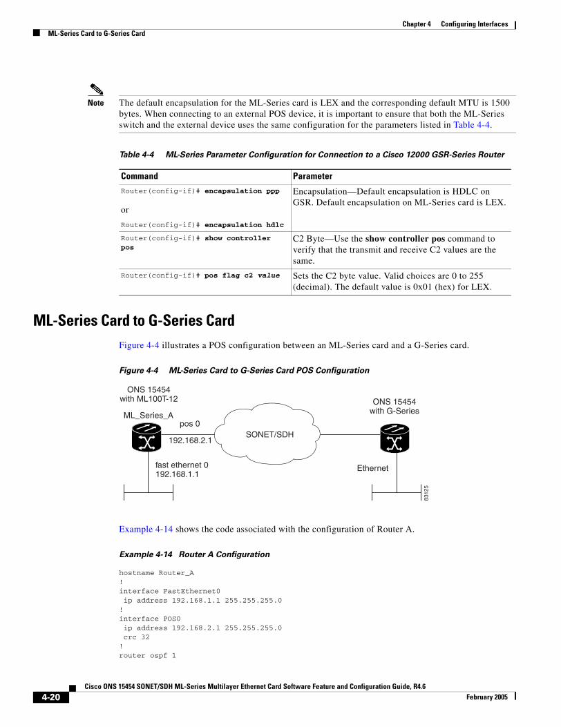
Chapter 4 Configuring InterfacesML-Series Card to G-Series Card
Note The default encapsulation for the ML-Series card is LEX and the corresponding default MTU is 1500 bytes. When connecting to an external POS device, it is important to ensure that both the ML-Series switch and the external device uses the same configuration for the parameters listed in Table 4-4.
ML-Series Card to G-Series CardFigure 4-4 illustrates a POS configuration between an ML-Series card and a G-Series card.
Figure 4-4 ML-Series Card to G-Series Card POS Configuration
Example 4-14 shows the code associated with the configuration of Router A.
Example 4-14 Router A Configuration
hostname Router_A!interface FastEthernet0 ip address 192.168.1.1 255.255.255.0!interface POS0 ip address 192.168.2.1 255.255.255.0 crc 32!router ospf 1
Table 4-4 ML-Series Parameter Configuration for Connection to a Cisco 12000 GSR-Series Router
Command Parameter
Router(config-if)# encapsulation ppp
or
Router(config-if)# encapsulation hdlc
Encapsulation—Default encapsulation is HDLC on GSR. Default encapsulation on ML-Series card is LEX.
Router(config-if)# show controller pos
C2 Byte—Use the show controller pos command to verify that the transmit and receive C2 values are the same.
Router(config-if)# pos flag c2 value Sets the C2 byte value. Valid choices are 0 to 255 (decimal). The default value is 0x01 (hex) for LEX.
ONS 15454with ML100T-12
fast ethernet 0
pos 0ML_Series_A
SONET/SDH
192.168.1.1
192.168.2.1
ONS 15454with G-Series
Ethernet
8312
5
4-20Cisco ONS 15454 SONET/SDH ML-Series Multilayer Ethernet Card Software Feature and Configuration Guide, R4.6
February 2005

Chapter 4 Configuring InterfacesML-Series Card to G-Series Card
log-adjacency-changes network 192.168.1.0 0.0.0.255 area 0 network 192.168.2.0 0.0.0.255 area 0
4-21Cisco ONS 15454 SONET/SDH ML-Series Multilayer Ethernet Card Software Feature and Configuration Guide, R4.6
February 2005

Chapter 4 Configuring InterfacesML-Series Card to G-Series Card
4-22Cisco ONS 15454 SONET/SDH ML-Series Multilayer Ethernet Card Software Feature and Configuration Guide, R4.6
February 2005
Cisco ONS 15454 SONET/SDH ML-Series Multilayer Ethernet Card SoftwarJanuary 2004
C H A P T E R 5
5Configuring Bridging
This chapter describes how to configure bridging for the ML-Series card. For more information about the Cisco IOS commands used in this chapter, refer to the Cisco IOS Command Reference publication.
This chapter includes the following major sections:
• Understanding Bridging, page 5-1
• Monitoring and Verifying Bridging, page 5-3
Caution Cisco Inter-Switch Link (ISL) and Cisco Dynamic Trunking Protocol (DTP) are not supported by the ML-Series cards, but the ML-Series broadcast forwards these formats. Using ISL or DTP on connecting devices is not recommended. Some Cisco devices attempt to use ISL or DTP by default.
Understanding BridgingThe ML-Series card can be configured to serve as an IP router and a bridge. Cisco IOS software supports transparent bridging for Fast Ethernet, Gigabit Ethernet, and POS. Cisco IOS software functionality combines the advantages of a spanning-tree bridge and a router. This combination provides the speed and protocol transparency of a spanning-tree bridge, along with the functionality, reliability, and security of a router.
To configure bridging, you must perform the following tasks in the modes indicated:
• In global configuration mode:
– Enable bridging of IP packets.
– Select the type of Spanning Tree Protocol (STP).
• In interface configuration mode:
– Determine which interfaces belong to the same bridge group.
These interfaces become part of the same spanning tree, allowing the ML-Series card to bridge all nonrouted traffic among the network interfaces comprising the bridge group. Interfaces not participating in a bridge group cannot forward bridged traffic.
If the destination address of the packet is known in the bridge table, the packet is forwarded on a single interface in the bridge group. If the packet’s destination is unknown in the bridge table, the packet is flooded on all forwarding interfaces in the bridge group. The bridge places source addresses in the bridge table as it learns them during the process of bridging.
5-1e Feature and Configuration Guide, R4.6

Chapter 5 Configuring BridgingConfiguring Bridging
A separate spanning-tree process runs for each configured bridge group. Each bridge group participates in a separate spanning tree. A bridge group establishes a spanning tree based on the bridge protocol data units (BPDUs) it receives on only its member interfaces.
Configuring BridgingUse the following steps to configure bridging:
Figure 5-1 shows a bridging example. Example 5-1 shows the code used to configure Router A. Example 5-2 shows the code used to configure Router B.
Figure 5-1 Bridging Example
Command Purpose
Step 1 Router(config)# no ip routing Enables bridging of IP packets. This command needs to be executed once per card, not once per bridge-group. This step is not done for integrated routing and bridging (IRB).
Step 2 Router(config)# bridge bridge-group-number protocol {rstp | ieee}
Assigns a bridge group number and defines the appropriate spanning-tree type: either IEEE 802.1D Spanning Tree Protocol or IEEE 802.1W Rapid Spanning Tree.
Step 3 Router(config)# bridge bridge-group-number priority number
(Optional) Assigns a specific priority to the bridge, to assist in the spanning-tree root definition. The lower the priority, the more likely the bridge is selected as the root.
Step 4 Router(config)# interface interface-type interface-number
Enters interface configuration mode to configure the interface of the ML-Series card.
Step 5 Router(config-if)# bridge-group bridge-group-number
Assigns a network interface to a bridge group.
Step 6 Router(config-if)# no shutdown Changes the shutdown state to up and enables the interface.
Step 7 Router(config-if)# end Returns to privileged EXEC mode.
Step 8 Router# copy running-config startup-config
(Optional) Saves your entries in the configuration file.
ONS 15454with ML100T-12
ONS 15454with ML100T-12
fast ethernet 0
pos 0pos 0
fast ethernet 0
ML_Series_A ML_Series_B
7897
2
SONET/SDH
5-2Cisco ONS 15454 SONET/SDH ML-Series Multilayer Ethernet Card Software Feature and Configuration Guide, R4.6
January 2004
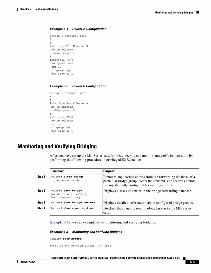
Chapter 5 Configuring BridgingMonitoring and Verifying Bridging
Example 5-1 Router A Configuration
bridge 1 protocol ieee!!interface FastEthernet0 no ip address bridge-group 1!interface POS0 no ip address crc 32bridge-group 1 pos flag c2 1
Example 5-2 Router B Configuration
bridge 1 protocol ieee!!interface FastEthernet0 no ip address bridge-group 1!interface POS0 no ip address crc 32bridge-group 1 pos flag c2 1
Monitoring and Verifying BridgingAfter you have set up the ML-Series card for bridging, you can monitor and verify its operation by performing the following procedure in privileged EXEC mode:
Example 5-3 shows an example of the monitoring and verifying bridging.
Example 5-3 Monitoring and Verifying Bridging
Router# show bridge
Total of 300 station blocks, 298 free
Command Purpose
Step 1 Router# clear bridge bridge-group-number
Removes any learned entries from the forwarding database of a particular bridge group, clears the transmit, and receives counts for any statically configured forwarding entries.
Step 2 Router# show bridge {bridge-group-number | interface-address}
Displays classes of entries in the bridge forwarding database.
Step 3 Router# show bridge verbose Displays detailed information about configured bridge groups.
Step 4 Router# show spanning-tree Displays the spanning tree topology known to the ML-Series card.
5-3Cisco ONS 15454 SONET/SDH ML-Series Multilayer Ethernet Card Software Feature and Configuration Guide, R4.6
January 2004
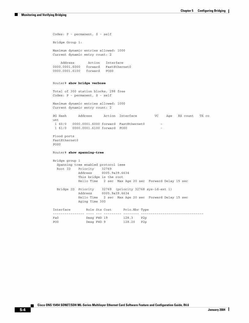
Chapter 5 Configuring BridgingMonitoring and Verifying Bridging
Codes: P - permanent, S - self
Bridge Group 1:
Maximum dynamic entries allowed: 1000Current dynamic entry count: 2
Address Action Interface0000.0001.6000 forward FastEthernet00000.0001.6100 forward POS0
Router# show bridge verbose
Total of 300 station blocks, 298 freeCodes: P - permanent, S - self
Maximum dynamic entries allowed: 1000Current dynamic entry count: 2
BG Hash Address Action Interface VC Age RX count TX count 1 60/0 0000.0001.6000 forward FastEthernet0 - 1 61/0 0000.0001.6100 forward POS0 -
Flood portsFastEthernet0POS0
Router# show spanning-tree
Bridge group 1 Spanning tree enabled protocol ieee Root ID Priority 32769 Address 0005.9a39.6634 This bridge is the root Hello Time 2 sec Max Age 20 sec Forward Delay 15 sec
Bridge ID Priority 32769 (priority 32768 sys-id-ext 1) Address 0005.9a39.6634 Hello Time 2 sec Max Age 20 sec Forward Delay 15 sec Aging Time 300
Interface Role Sts Cost Prio.Nbr Type---------------- ---- --- --------- -------- --------------------------------Fa0 Desg FWD 19 128.3 P2pPO0 Desg FWD 9 128.20 P2p
5-4Cisco ONS 15454 SONET/SDH ML-Series Multilayer Ethernet Card Software Feature and Configuration Guide, R4.6
January 2004

Cisco ONS 15454 SONET/SDH ML-Series Multilayer Ethernet Card SoftwarJanuary 2004
C H A P T E R 6
Configuring STP and RSTPThis chapter describes the IEEE 802.1D Spanning Tree Protocol (STP) and the ML-Series implementation of the IEEE 802.1W Rapid Spanning Tree Protocol (RSTP). It also explains how to configure STP and RSTP on the ML-Series card.
This chapter consists of these sections:
• STP Features, page 6-1
• RSTP, page 6-9
• Interoperability with IEEE 802.1D STP, page 6-15
• Configuring STP and RSTP Features, page 6-15
• Verifying and Monitoring STP and RSTP Status, page 6-20
STP FeaturesThese sections describe how the spanning-tree features work:
• STP Overview, page 6-2
• Supported STP Instances, page 6-2
• Bridge Protocol Data Units, page 6-2
• Election of the Root Switch, page 6-3
• Bridge ID, Switch Priority, and Extended System ID, page 6-4
• Spanning-Tree Timers, page 6-4
• Creating the Spanning-Tree Topology, page 6-4
• Spanning-Tree Interface States, page 6-5
• Spanning-Tree Address Management, page 6-8
• STP and IEEE 802.1Q Trunks, page 6-8
• Spanning Tree and Redundant Connectivity, page 6-8
• Accelerated Aging to Retain Connectivity, page 6-9
6-1e Feature and Configuration Guide, R4.6

Chapter 6 Configuring STP and RSTPSTP Overview
STP OverviewSTP is a Layer 2 link management protocol that provides path redundancy while preventing loops in the network. For a Layer 2 Ethernet network to function properly, only one active path can exist between any two stations. Spanning-tree operation is transparent to end stations, which cannot detect whether they are connected to a single LAN segment or a switched LAN of multiple segments.
When you create fault-tolerant internetworks, you must have a loop-free path between all nodes in a network. The spanning-tree algorithm calculates the best loop-free path throughout a switched Layer 2 network. Switches send and receive spanning-tree frames, called bridge protocol data units (BPDUs), at regular intervals. The switches do not forward these frames, but use the frames to construct a loop-free path.
Multiple active paths among end stations cause loops in the network. If a loop exists in the network, end stations might receive duplicate messages. Switches might also learn end-station MAC addresses on multiple Layer 2 interfaces. These conditions result in an unstable network.
Spanning tree defines a tree with a root switch and a loop-free path from the root to all switches in the Layer 2 network. Spanning tree forces redundant data paths into a standby (blocked) state. If a network segment in the spanning tree fails and a redundant path exists, the spanning-tree algorithm recalculates the spanning-tree topology and activates the standby path.
When two interfaces on a switch are part of a loop, the spanning-tree port priority and path cost settings determine which interface is put in the forwarding state and which is put in the blocking state. The port priority value represents the location of an interface in the network topology and how well it is located to pass traffic. The path cost value represents media speed.
Supported STP InstancesThe ML-Series card supports the per-VLAN spanning tree (PVST+) and a maximum of 255 spanning-tree instances.
Bridge Protocol Data UnitsThe stable, active, spanning-tree topology of a switched network is determined by these elements:
• Unique bridge ID (switch priority and MAC address) associated with each VLAN on each switch
• Spanning-tree path cost to the root switch
• Port identifier (port priority and MAC address) associated with each Layer 2 interface
When the switches in a network are powered up, each functions as the root switch. Each switch sends a configuration BPDU through all of its ports. The BPDUs communicate and compute the spanning-tree topology. Each configuration BPDU contains this information:
• Unique bridge ID of the switch that the sending switch identifies as the root switch
• Spanning-tree path cost to the root
• Bridge ID of the sending switch
• Message age
• Identifier of the sending interface
• Values for the hello, forward delay, and max-age protocol timers
6-2Cisco ONS 15454 SONET/SDH ML-Series Multilayer Ethernet Card Software Feature and Configuration Guide, R4.6
January 2004
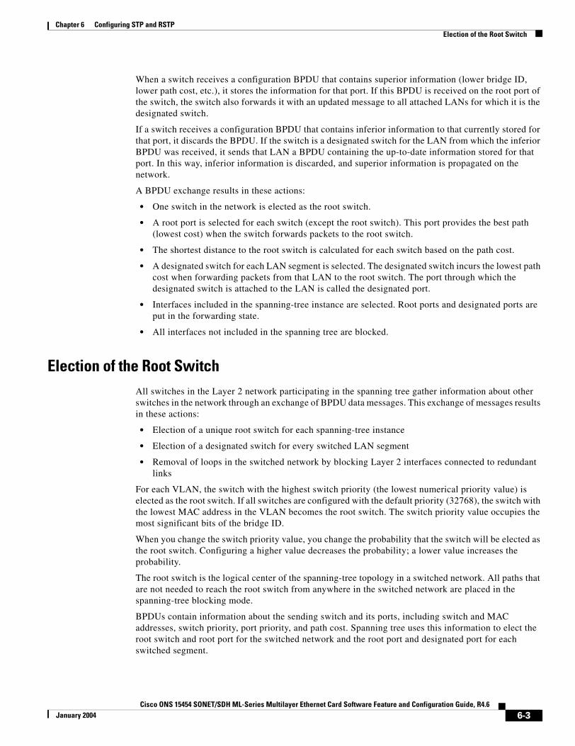
Chapter 6 Configuring STP and RSTPElection of the Root Switch
When a switch receives a configuration BPDU that contains superior information (lower bridge ID, lower path cost, etc.), it stores the information for that port. If this BPDU is received on the root port of the switch, the switch also forwards it with an updated message to all attached LANs for which it is the designated switch.
If a switch receives a configuration BPDU that contains inferior information to that currently stored for that port, it discards the BPDU. If the switch is a designated switch for the LAN from which the inferior BPDU was received, it sends that LAN a BPDU containing the up-to-date information stored for that port. In this way, inferior information is discarded, and superior information is propagated on the network.
A BPDU exchange results in these actions:
• One switch in the network is elected as the root switch.
• A root port is selected for each switch (except the root switch). This port provides the best path (lowest cost) when the switch forwards packets to the root switch.
• The shortest distance to the root switch is calculated for each switch based on the path cost.
• A designated switch for each LAN segment is selected. The designated switch incurs the lowest path cost when forwarding packets from that LAN to the root switch. The port through which the designated switch is attached to the LAN is called the designated port.
• Interfaces included in the spanning-tree instance are selected. Root ports and designated ports are put in the forwarding state.
• All interfaces not included in the spanning tree are blocked.
Election of the Root SwitchAll switches in the Layer 2 network participating in the spanning tree gather information about other switches in the network through an exchange of BPDU data messages. This exchange of messages results in these actions:
• Election of a unique root switch for each spanning-tree instance
• Election of a designated switch for every switched LAN segment
• Removal of loops in the switched network by blocking Layer 2 interfaces connected to redundant links
For each VLAN, the switch with the highest switch priority (the lowest numerical priority value) is elected as the root switch. If all switches are configured with the default priority (32768), the switch with the lowest MAC address in the VLAN becomes the root switch. The switch priority value occupies the most significant bits of the bridge ID.
When you change the switch priority value, you change the probability that the switch will be elected as the root switch. Configuring a higher value decreases the probability; a lower value increases the probability.
The root switch is the logical center of the spanning-tree topology in a switched network. All paths that are not needed to reach the root switch from anywhere in the switched network are placed in the spanning-tree blocking mode.
BPDUs contain information about the sending switch and its ports, including switch and MAC addresses, switch priority, port priority, and path cost. Spanning tree uses this information to elect the root switch and root port for the switched network and the root port and designated port for each switched segment.
6-3Cisco ONS 15454 SONET/SDH ML-Series Multilayer Ethernet Card Software Feature and Configuration Guide, R4.6
January 2004

Chapter 6 Configuring STP and RSTPBridge ID, Switch Priority, and Extended System ID
Bridge ID, Switch Priority, and Extended System IDThe IEEE 802.1D standard requires that each switch has an unique bridge identifier (bridge ID), which determines the selection of the root switch. Because each VLAN is considered as a different logical bridge with PVST+, the same switch must have as many different bridge IDs as VLANs configured on it. Each VLAN on the switch has a unique 8-byte bridge ID; the two most-significant bytes are used for the switch priority, and the remaining six bytes are derived from the switch MAC address.
The ML-Series card supports the IEEE 802.1T spanning-tree extensions, and some of the bits previously used for the switch priority are now used as the bridge ID. The result is that fewer MAC addresses are reserved for the switch, and a larger range of VLAN IDs can be supported, all while maintaining the uniqueness of the bridge ID. As shown in Table 6-1, the two bytes previously used for the switch priority are reallocated into a 4-bit priority value and a 12-bit extended system ID value equal to the bridge ID. In earlier releases, the switch priority is a 16-bit value.
Spanning tree uses the extended system ID, the switch priority, and the allocated spanning-tree MAC address to make the bridge ID unique for each VLAN. With earlier releases, spanning tree used one MAC address per VLAN to make the bridge ID unique for each VLAN.
Spanning-Tree TimersTable 6-2 describes the timers that affect the entire spanning-tree performance.
Creating the Spanning-Tree TopologyIn Figure 6-1, Switch A is elected as the root switch because the switch priority of all the switches is set to the default (32768) and Switch A has the lowest MAC address. However, because of traffic patterns, number of forwarding interfaces, or link types, Switch A might not be the ideal root switch. By increasing the priority (lowering the numerical value) of the ideal switch so that it becomes the root switch, you force a spanning-tree recalculation to form a new topology with the ideal switch as the root.
Table 6-1 Switch Priority Value and Extended System ID
Switch Priority Value Extended System ID (Set Equal to the Bridge ID)
Bit 16 Bit 15 Bit 14 Bit 13 Bit 12 Bit 11 Bit 10 Bit 9 Bit 8 Bit 7 Bit 6 Bit 5 Bit 4 Bit 3 Bit 2 Bit 1
32768 16384 8192 4096 2048 1024 512 256 128 64 32 16 8 4 2 1
Table 6-2 Spanning-Tree Timers
Variable Description
Hello timer When this timer expires, the interface sends out a Hello message to the neighboring nodes.
Forward-delay timer Determines how long each of the listening and learning states last before the interface begins forwarding.
Maximum-age timer Determines the amount of time the switch stores protocol information received on an interface.
6-4Cisco ONS 15454 SONET/SDH ML-Series Multilayer Ethernet Card Software Feature and Configuration Guide, R4.6
January 2004
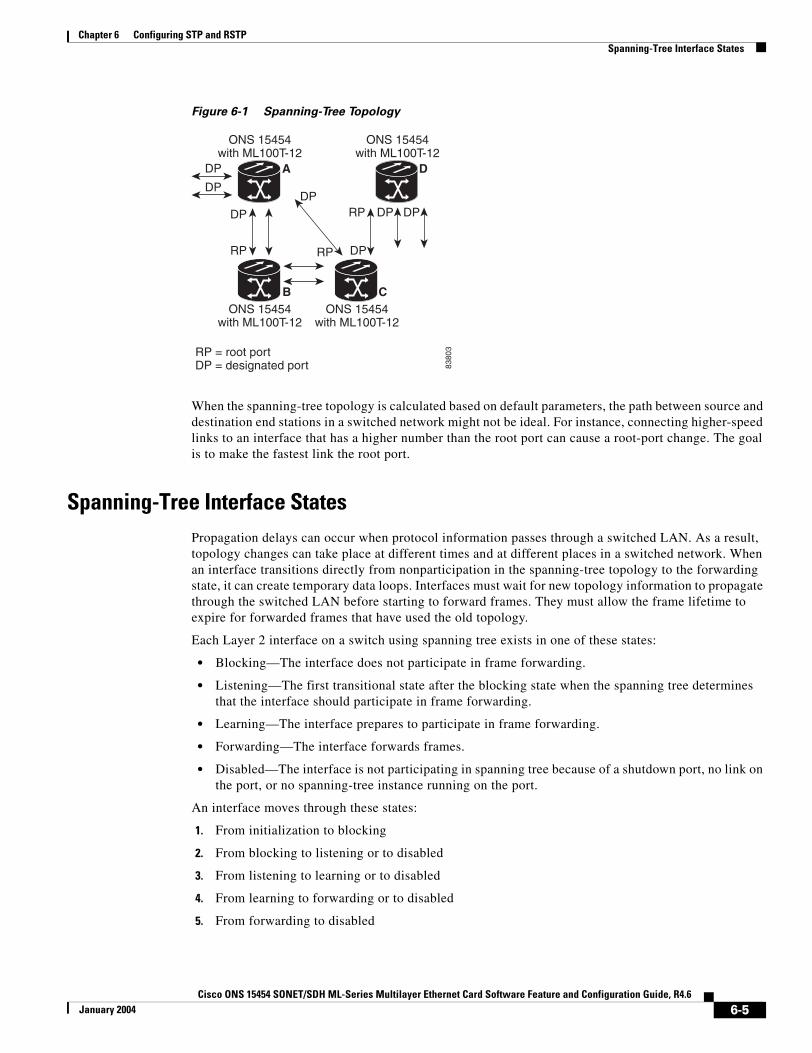
Chapter 6 Configuring STP and RSTPSpanning-Tree Interface States
Figure 6-1 Spanning-Tree Topology
When the spanning-tree topology is calculated based on default parameters, the path between source and destination end stations in a switched network might not be ideal. For instance, connecting higher-speed links to an interface that has a higher number than the root port can cause a root-port change. The goal is to make the fastest link the root port.
Spanning-Tree Interface StatesPropagation delays can occur when protocol information passes through a switched LAN. As a result, topology changes can take place at different times and at different places in a switched network. When an interface transitions directly from nonparticipation in the spanning-tree topology to the forwarding state, it can create temporary data loops. Interfaces must wait for new topology information to propagate through the switched LAN before starting to forward frames. They must allow the frame lifetime to expire for forwarded frames that have used the old topology.
Each Layer 2 interface on a switch using spanning tree exists in one of these states:
• Blocking—The interface does not participate in frame forwarding.
• Listening—The first transitional state after the blocking state when the spanning tree determines that the interface should participate in frame forwarding.
• Learning—The interface prepares to participate in frame forwarding.
• Forwarding—The interface forwards frames.
• Disabled—The interface is not participating in spanning tree because of a shutdown port, no link on the port, or no spanning-tree instance running on the port.
An interface moves through these states:
1. From initialization to blocking
2. From blocking to listening or to disabled
3. From listening to learning or to disabled
4. From learning to forwarding or to disabled
5. From forwarding to disabled
8380
3
DP
DP
RP DP
DPRP
DP
RP = root portDP = designated port
DP
RP
DP
DA
CB
ONS 15454with ML100T-12
ONS 15454with ML100T-12
ONS 15454with ML100T-12
ONS 15454with ML100T-12
6-5Cisco ONS 15454 SONET/SDH ML-Series Multilayer Ethernet Card Software Feature and Configuration Guide, R4.6
January 2004
Chapter 6 Configuring STP and RSTPSpanning-Tree Interface States
Figure 6-2 illustrates how an interface moves through the states.
Figure 6-2 Spanning-Tree Interface States
When you power up the switch, STP is enabled by default, and every interface in the switch, VLAN, or network goes through the blocking state and the transitory states of listening and learning. Spanning tree stabilizes each interface at the forwarding or blocking state.
When the spanning-tree algorithm places a Layer 2 interface in the forwarding state, this process occurs:
1. The interface is in the listening state while spanning tree waits for protocol information to transition the interface to the blocking state.
2. While spanning tree waits for the forward-delay timer to expire, it moves the interface to the learning state and resets the forward-delay timer.
3. In the learning state, the interface continues to block frame forwarding as the switch learns end-station location information for the forwarding database.
4. When the forward-delay timer expires, spanning tree moves the interface to the forwarding state, where both learning and frame forwarding are enabled.
Blocking State
A Layer 2 interface in the blocking state does not participate in frame forwarding. After initialization, a BPDU is sent to each interface in the switch. A switch initially functions as the root until it exchanges BPDUs with other switches. This exchange establishes which switch in the network is the root or root switch. If there is only one switch in the network, no exchange occurs, the forward-delay timer expires, and the interfaces move to the listening state. An interface always enters the blocking state after switch initialization.
An interface in the blocking state performs as follows:
• Discards frames received on the port
• Discards frames switched from another interface for forwarding
• Does not learn addresses
• Receives BPDUs
Power-oninitialization
Blockingstate
4356
9
Listeningstate
Disabledstate
Learningstate
Forwardingstate
6-6Cisco ONS 15454 SONET/SDH ML-Series Multilayer Ethernet Card Software Feature and Configuration Guide, R4.6
January 2004
Chapter 6 Configuring STP and RSTPSpanning-Tree Interface States
Listening State
The listening state is the first state a Layer 2 interface enters after the blocking state. The interface enters this state when the spanning tree determines that the interface should participate in frame forwarding.
An interface in the listening state performs as follows:
• Discards frames received on the port
• Discards frames switched from another interface for forwarding
• Does not learn addresses
• Receives BPDUs
Learning State
A Layer 2 interface in the learning state prepares to participate in frame forwarding. The interface enters the learning state from the listening state.
An interface in the learning state performs as follows:
• Discards frames received on the port
• Discards frames switched from another interface for forwarding
• Learns addresses
• Receives BPDUs
Forwarding State
A Layer 2 interface in the forwarding state forwards frames. The interface enters the forwarding state from the learning state.
An interface in the forwarding state performs as follows:
• Receives and forwards frames received on the port
• Forwards frames switched from another port
• Learns addresses
• Receives BPDUs
Disabled State
A Layer 2 interface in the disabled state does not participate in frame forwarding or in the spanning tree. An interface in the disabled state is nonoperational.
A disabled interface performs as follows:
• Forwards frames switched from another interface for forwarding
• Learns addresses
• Does not receive BPDUs
6-7Cisco ONS 15454 SONET/SDH ML-Series Multilayer Ethernet Card Software Feature and Configuration Guide, R4.6
January 2004
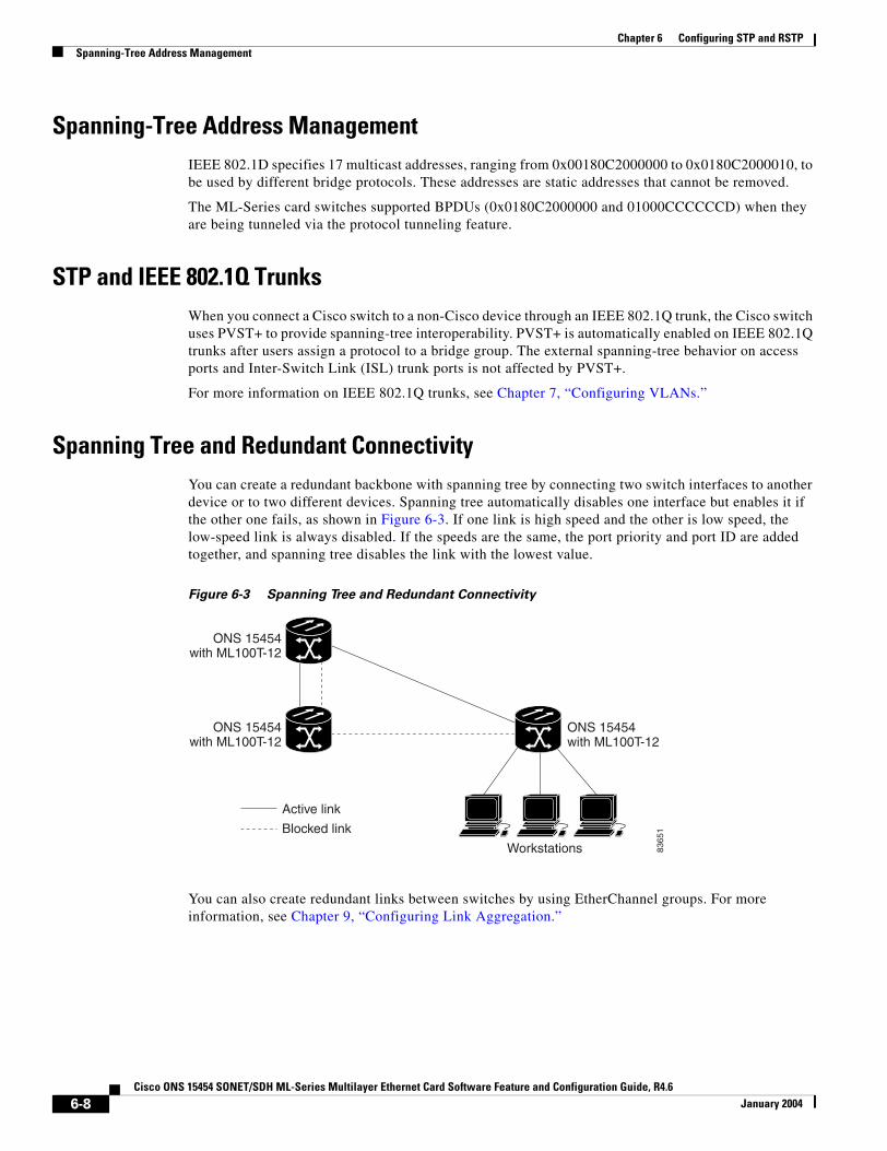
Chapter 6 Configuring STP and RSTPSpanning-Tree Address Management
Spanning-Tree Address ManagementIEEE 802.1D specifies 17 multicast addresses, ranging from 0x00180C2000000 to 0x0180C2000010, to be used by different bridge protocols. These addresses are static addresses that cannot be removed.
The ML-Series card switches supported BPDUs (0x0180C2000000 and 01000CCCCCCD) when they are being tunneled via the protocol tunneling feature.
STP and IEEE 802.1Q TrunksWhen you connect a Cisco switch to a non-Cisco device through an IEEE 802.1Q trunk, the Cisco switch uses PVST+ to provide spanning-tree interoperability. PVST+ is automatically enabled on IEEE 802.1Q trunks after users assign a protocol to a bridge group. The external spanning-tree behavior on access ports and Inter-Switch Link (ISL) trunk ports is not affected by PVST+.
For more information on IEEE 802.1Q trunks, see Chapter 7, “Configuring VLANs.”
Spanning Tree and Redundant ConnectivityYou can create a redundant backbone with spanning tree by connecting two switch interfaces to another device or to two different devices. Spanning tree automatically disables one interface but enables it if the other one fails, as shown in Figure 6-3. If one link is high speed and the other is low speed, the low-speed link is always disabled. If the speeds are the same, the port priority and port ID are added together, and spanning tree disables the link with the lowest value.
Figure 6-3 Spanning Tree and Redundant Connectivity
You can also create redundant links between switches by using EtherChannel groups. For more information, see Chapter 9, “Configuring Link Aggregation.”
Workstations
Active link
Blocked link
8365
1
ONS 15454with ML100T-12
ONS 15454with ML100T-12
ONS 15454with ML100T-12
6-8Cisco ONS 15454 SONET/SDH ML-Series Multilayer Ethernet Card Software Feature and Configuration Guide, R4.6
January 2004
Chapter 6 Configuring STP and RSTPAccelerated Aging to Retain Connectivity
Accelerated Aging to Retain ConnectivityThe default for aging dynamic addresses is 5 minutes, which is the default setting of the bridge bridge-group-number aging-time global configuration command. However, a spanning-tree reconfiguration can cause many station locations to change. Because these stations could be unreachable for 5 minutes or more during a reconfiguration, the address-aging time is accelerated so that station addresses can be dropped from the address table and then relearned.
Because each VLAN is a separate spanning-tree instance, the switch accelerates aging on a per-VLAN basis. A spanning-tree reconfiguration on one VLAN can cause the dynamic addresses learned on that VLAN to be subject to accelerated aging. Dynamic addresses on other VLANs can be unaffected and remain subject to the aging interval entered for the switch.
RSTPRSTP provides rapid convergence of the spanning tree. It improves the fault tolerance of the network because a failure in one instance (forwarding path) does not affect other instances (forwarding paths). The most common initial deployment of RSTP is in the backbone and distribution layers of a Layer 2 switched network; this deployment provides the highly available network required in a service-provider environment.
RSTP improves the operation of the spanning tree while maintaining backward compatibility with equipment that is based on the (original) IEEE 802.1D spanning tree.
RSTP takes advantage of point-to-point wiring and provides rapid convergence of the spanning tree. Reconfiguration of the spanning tree can occur in less than 2 second (in contrast to 50 seconds with the default settings in the IEEE 802.1D spanning tree), which is critical for networks carrying delay-sensitive traffic such as voice and video.
These sections describe how RSTP works:
• Supported RSTP Instances, page 6-9
• Port Roles and the Active Topology, page 6-10
• Rapid Convergence, page 6-11
• Synchronization of Port Roles, page 6-12
• Bridge Protocol Data Unit Format and Processing, page 6-13
• Topology Changes, page 6-14
Supported RSTP InstancesThe ML Series supports per-VLAN rapid spanning tree (PVRST) and a maximum of 255 rapid spanning-tree instances.
6-9Cisco ONS 15454 SONET/SDH ML-Series Multilayer Ethernet Card Software Feature and Configuration Guide, R4.6
January 2004
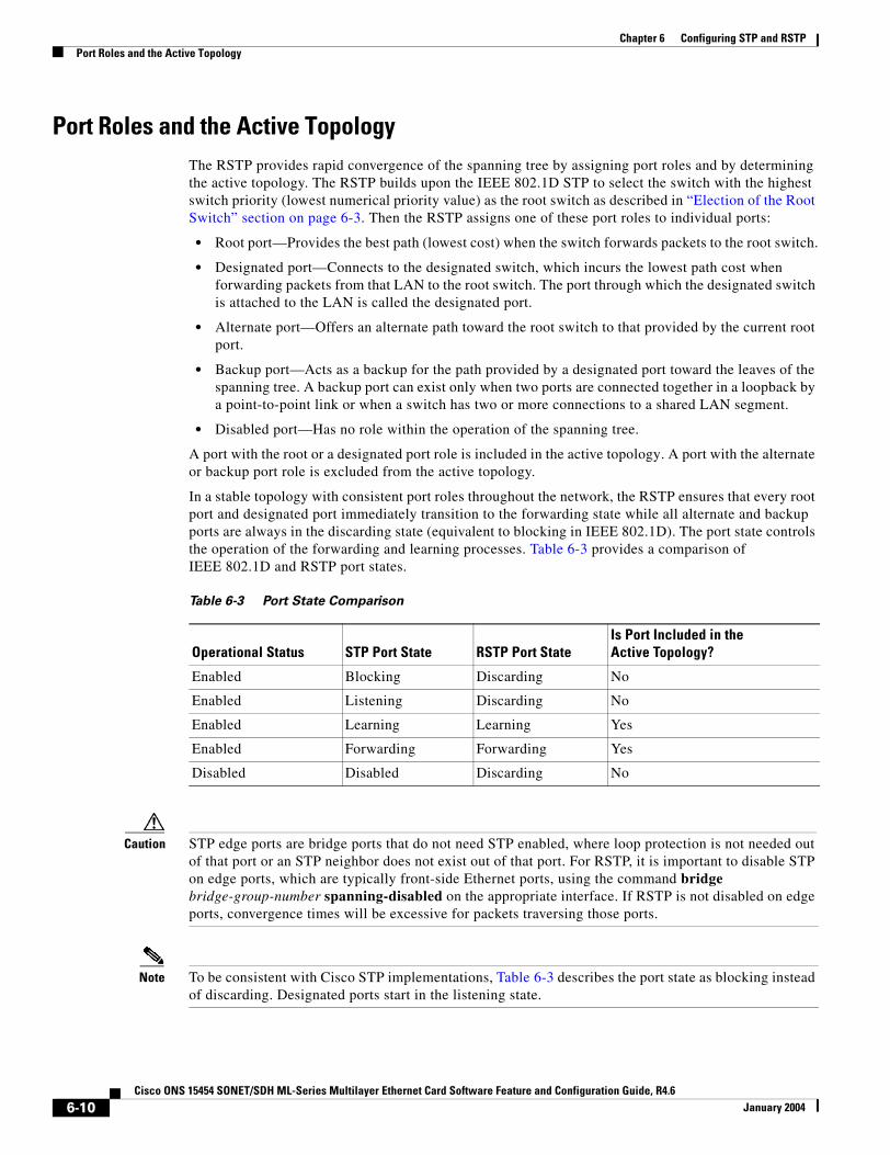
Chapter 6 Configuring STP and RSTPPort Roles and the Active Topology
Port Roles and the Active TopologyThe RSTP provides rapid convergence of the spanning tree by assigning port roles and by determining the active topology. The RSTP builds upon the IEEE 802.1D STP to select the switch with the highest switch priority (lowest numerical priority value) as the root switch as described in “Election of the Root Switch” section on page 6-3. Then the RSTP assigns one of these port roles to individual ports:
• Root port—Provides the best path (lowest cost) when the switch forwards packets to the root switch.
• Designated port—Connects to the designated switch, which incurs the lowest path cost when forwarding packets from that LAN to the root switch. The port through which the designated switch is attached to the LAN is called the designated port.
• Alternate port—Offers an alternate path toward the root switch to that provided by the current root port.
• Backup port—Acts as a backup for the path provided by a designated port toward the leaves of the spanning tree. A backup port can exist only when two ports are connected together in a loopback by a point-to-point link or when a switch has two or more connections to a shared LAN segment.
• Disabled port—Has no role within the operation of the spanning tree.
A port with the root or a designated port role is included in the active topology. A port with the alternate or backup port role is excluded from the active topology.
In a stable topology with consistent port roles throughout the network, the RSTP ensures that every root port and designated port immediately transition to the forwarding state while all alternate and backup ports are always in the discarding state (equivalent to blocking in IEEE 802.1D). The port state controls the operation of the forwarding and learning processes. Table 6-3 provides a comparison of IEEE 802.1D and RSTP port states.
Caution STP edge ports are bridge ports that do not need STP enabled, where loop protection is not needed out of that port or an STP neighbor does not exist out of that port. For RSTP, it is important to disable STP on edge ports, which are typically front-side Ethernet ports, using the command bridge bridge-group-number spanning-disabled on the appropriate interface. If RSTP is not disabled on edge ports, convergence times will be excessive for packets traversing those ports.
Note To be consistent with Cisco STP implementations, Table 6-3 describes the port state as blocking instead of discarding. Designated ports start in the listening state.
Table 6-3 Port State Comparison
Operational Status STP Port State RSTP Port StateIs Port Included in the Active Topology?
Enabled Blocking Discarding No
Enabled Listening Discarding No
Enabled Learning Learning Yes
Enabled Forwarding Forwarding Yes
Disabled Disabled Discarding No
6-10Cisco ONS 15454 SONET/SDH ML-Series Multilayer Ethernet Card Software Feature and Configuration Guide, R4.6
January 2004
Chapter 6 Configuring STP and RSTPRapid Convergence
Rapid ConvergenceThe RSTP provides for rapid recovery of connectivity following the failure of switch, a switch port, or a LAN. It provides rapid convergence for new root ports, and ports connected through point-to-point links as follows:
• Root ports—If the RSTP selects a new root port, it blocks the old root port and immediately transitions the new root port to the forwarding state.
• Point-to-point links—If you connect a port to another port through a point-to-point link and the local port becomes a designated port, it negotiates a rapid transition with the other port by using the proposal-agreement handshake to ensure a loop-free topology.
As shown in Figure 6-4, Switch A is connected to Switch B through a point-to-point link, and all of the ports are in the blocking state. Assume that the priority of Switch A is a smaller numerical value than the priority of Switch B. Switch A sends a proposal message (a configuration BPDU with the proposal flag set) to Switch B, proposing itself as the designated switch.
After receiving the proposal message, Switch B selects as its new root port the port from which the proposal message was received, forces all non edge ports to the blocking state, and sends an agreement message (a BPDU with the agreement flag set) through its new root port.
After receiving an agreement message from Switch B, Switch A also immediately transitions its designated port to the forwarding state. No loops in the network are formed because Switch B blocked all of its non edge ports and because there is a point-to-point link between Switches A and B.
When Switch C is connected to Switch B, a similar set of handshaking messages are exchanged. Switch C selects the port connected to Switch B as its root port, and both ends immediately transition to the forwarding state. With each iteration of this handshaking process, one more switch joins the active topology. As the network converges, this proposal-agreement handshaking progresses from the root toward the leaves of the spanning tree.
The switch determines the link type from the port duplex mode: a full-duplex port is considered to have a point-to-point connection; a half-duplex port is considered to have a shared connection.
6-11Cisco ONS 15454 SONET/SDH ML-Series Multilayer Ethernet Card Software Feature and Configuration Guide, R4.6
January 2004
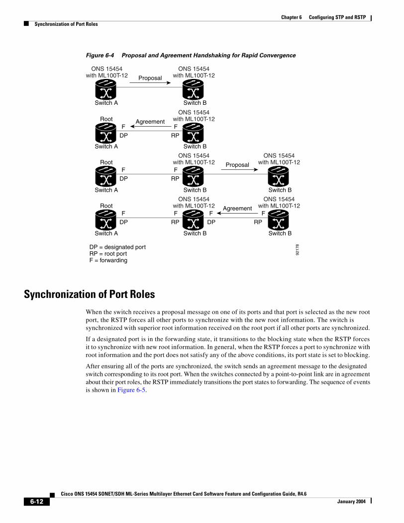
Chapter 6 Configuring STP and RSTPSynchronization of Port Roles
Figure 6-4 Proposal and Agreement Handshaking for Rapid Convergence
Synchronization of Port RolesWhen the switch receives a proposal message on one of its ports and that port is selected as the new root port, the RSTP forces all other ports to synchronize with the new root information. The switch is synchronized with superior root information received on the root port if all other ports are synchronized.
If a designated port is in the forwarding state, it transitions to the blocking state when the RSTP forces it to synchronize with new root information. In general, when the RSTP forces a port to synchronize with root information and the port does not satisfy any of the above conditions, its port state is set to blocking.
After ensuring all of the ports are synchronized, the switch sends an agreement message to the designated switch corresponding to its root port. When the switches connected by a point-to-point link are in agreement about their port roles, the RSTP immediately transitions the port states to forwarding. The sequence of events is shown in Figure 6-5.
Proposal
FF
RPDP
FF
RPDP
FF
RPDP
FF
RPDP
9217
8
AgreementRoot
Switch A
Switch A
Switch A
Switch A
Switch B
Switch B
Switch B
Switch B
Switch B
Switch B
Proposal
Agreement
DP = designated portRP = root portF = forwarding
ONS 15454with ML100T-12
ONS 15454with ML100T-12
ONS 15454with ML100T-12
RootONS 15454
with ML100T-12
RootONS 15454
with ML100T-12
ONS 15454with ML100T-12
ONS 15454with ML100T-12
6-12Cisco ONS 15454 SONET/SDH ML-Series Multilayer Ethernet Card Software Feature and Configuration Guide, R4.6
January 2004
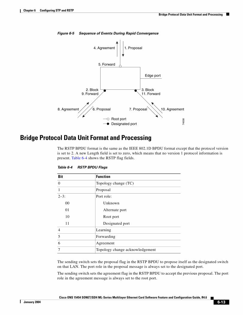
Chapter 6 Configuring STP and RSTPBridge Protocol Data Unit Format and Processing
Figure 6-5 Sequence of Events During Rapid Convergence
Bridge Protocol Data Unit Format and ProcessingThe RSTP BPDU format is the same as the IEEE 802.1D BPDU format except that the protocol version is set to 2. A new Length field is set to zero, which means that no version 1 protocol information is present. Table 6-4 shows the RSTP flag fields.
The sending switch sets the proposal flag in the RSTP BPDU to propose itself as the designated switch on that LAN. The port role in the proposal message is always set to the designated port.
The sending switch sets the agreement flag in the RSTP BPDU to accept the previous proposal. The port role in the agreement message is always set to the root port.
2. Block9. Forward
1. Proposal4. Agreement
6. Proposal
Root portDesignated port
8. Agreement 10. Agreement
Edge port
7. Proposal
5. Forward
3. Block11. Forward
7400
8
Table 6-4 RSTP BPDU Flags
Bit Function
0 Topology change (TC)
1 Proposal
2–3:
00
01
10
11
Port role:
Unknown
Alternate port
Root port
Designated port
4 Learning
5 Forwarding
6 Agreement
7 Topology change acknowledgement
6-13Cisco ONS 15454 SONET/SDH ML-Series Multilayer Ethernet Card Software Feature and Configuration Guide, R4.6
January 2004

Chapter 6 Configuring STP and RSTPTopology Changes
The RSTP does not have a separate topology change notification (TCN) BPDU. It uses the topology change (TC) flag to show the topology changes. However, for interoperability with IEEE 802.1D switches, the RSTP switch processes and generates TCN BPDUs.
The learning and forwarding flags are set according to the state of the sending port.
Processing Superior BPDU Information
If a port receives superior root information (lower bridge ID, lower path cost, etc.) than currently stored for the port, the RSTP triggers a reconfiguration. If the port is proposed and is selected as the new root port, RSTP forces all the other ports to synchronize.
If the BPDU received is an RSTP BPDU with the proposal flag set, the switch sends an agreement message after all of the other ports are synchronized. If the BPDU is an IEEE 802.1D BPDU, the switch does not set the proposal flag and starts the forward-delay timer for the port. The new root port requires twice the forward-delay time to transition to the forwarding state.
If the superior information received on the port causes the port to become a backup or alternate port, RSTP sets the port to the blocking state but does not send the agreement message. The designated port continues sending BPDUs with the proposal flag set until the forward-delay timer expires, at which time the port transitions to the forwarding state.
Processing Inferior BPDU Information
If a designated port receives an inferior BPDU (higher bridge ID, higher path cost, etc.) than currently stored for the port with a designated port role, it immediately replies with its own information.
Topology ChangesThis section describes the differences between the RSTP and the IEEE 802.1D in handling spanning-tree topology changes.
• Detection—Unlike IEEE 802.1D in which any transition between the blocking and the forwarding state causes a topology change, only transitions from the blocking to the forwarding state cause a topology change with RSTP. (Only an increase in connectivity is considered a topology change.) State changes on an edge port do not cause a topology change. When an RSTP switch detects a topology change, it flushes the learned information on all of its non edge ports.
• Notification—Unlike IEEE 802.1D, which uses TCN BPDUs, the RSTP does not use them. However, for IEEE 802.1D interoperability, an RSTP switch processes and generates TCN BPDUs.
• Acknowledgement—When an RSTP switch receives a TCN message on a designated port from an IEEE 802.1D switch, it replies with an IEEE 802.1D configuration BPDU with the topology change acknowledgement bit set. However, if the TC-while timer (the same as the topology-change timer in IEEE 802.1D) is active on a root port connected to an IEEE 802.1D switch and a configuration BPDU with the topology change acknowledgement bit set is received, the TC-while timer is reset.
This behavior is only required to support IEEE 802.1D switches. The RSTP BPDUs never have the topology change acknowledgement bit set.
• Propagation—When an RSTP switch receives a TC message from another switch through a designated or root port, it propagates the topology change to all of its non edge, edge, designated ports, and root port (excluding the port on which it is received). The switch starts the TC-while timer for all such ports and flushes the information learned on them.
6-14Cisco ONS 15454 SONET/SDH ML-Series Multilayer Ethernet Card Software Feature and Configuration Guide, R4.6
January 2004
Chapter 6 Configuring STP and RSTPInteroperability with IEEE 802.1D STP
• Protocol migration—For backward compatibility with IEEE 802.1D switches, RSTP selectively sends IEEE 802.1D configuration BPDUs and TCN BPDUs on a per-port basis.
When a port is initialized, the timer is started (which specifies the minimum time during which RSTP BPDUs are sent), and RSTP BPDUs are sent. While this timer is active, the switch processes all BPDUs received on that port and ignores the protocol type.
If the switch receives an IEEE 802.1D BPDU after the port’s migration-delay timer has expired, it assumes that it is connected to an IEEE 802.1D switch and starts using only IEEE 802.1D BPDUs. However, if the RSTP switch is using IEEE 802.1D BPDUs on a port and receives an RSTP BPDU after the timer has expired, it restarts the timer and starts using RSTP BPDUs on that port.
Interoperability with IEEE 802.1D STPA switch running RSTP supports a built-in protocol migration mechanism that enables it to interoperate with legacy IEEE 802.1D switches. If this switch receives a legacy IEEE 802.1D configuration BPDU (a BPDU with the protocol version set to 0), it sends only IEEE 802.1D BPDUs on that port.
However, the switch does not automatically revert to the RSTP mode if it no longer receives IEEE 802.1D BPDUs because it cannot determine whether the legacy switch has been removed from the link unless the legacy switch is the designated switch. Also, a switch might continue to assign a boundary role to a port when the switch to which this switch is connected has joined the region.
Configuring STP and RSTP FeaturesThese sections describe how to configure spanning-tree features:
• Default STP and RSTP Configuration, page 6-16
• Disabling STP and RSTP, page 6-16
• Configuring the Root Switch, page 6-17
• Configuring the Port Priority, page 6-17
• Configuring the Path Cost, page 6-18
• Configuring the Switch Priority of a Bridge Group, page 6-19
• Configuring the Hello Time, page 6-19
• Configuring the Forwarding-Delay Time for a Bridge Group, page 6-20
• Configuring the Maximum-Aging Time for a Bridge Group, page 6-20
6-15Cisco ONS 15454 SONET/SDH ML-Series Multilayer Ethernet Card Software Feature and Configuration Guide, R4.6
January 2004
Chapter 6 Configuring STP and RSTPDefault STP and RSTP Configuration
Default STP and RSTP ConfigurationTable 6-5 shows the default STP and RSTP configuration.
Disabling STP and RSTPSTP is enabled by default on VLAN 1 and on all newly created VLANs up to the specified spanning-tree limit of 255. Disable STP only if you are sure there are no loops in the network topology.
Caution STP edge ports are bridge ports that do not need STP enabled, where loop protection is not needed out of that port or an STP neighbor does not exist out of that port. For RSTP, it is important to disable STP on edge ports, which are typically front-side Ethernet ports, using the command bridge bridge-group-number spanning-disabled on the appropriate interface. If RSTP is not disabled on edge ports, convergence times will be excessive for packets traversing those ports.
Caution When STP is disabled and loops are present in the topology, excessive traffic and indefinite packet duplication can drastically reduce network performance.
Table 6-5 Default STP and RSTP Configuration
Feature Default Setting
Enable state Up to 255 spanning-tree instances can be enabled.
Switch priority 32768 + Bridge ID
Spanning-tree port priority (configurable on a per-interface basis—used on interfaces configured as Layer 2 access ports)
128
Spanning-tree port cost (configurable on a per-interface basis) 1000 Mbps: 4
100 Mbps: 19
10 Mbps: 100
STS-1: 34
STS-3c: 14
STS-6c: 9
STS-9c: 7
STS-12c: 6
STS-24c: 3
Hello time 2 seconds
Forward-delay time 15 seconds
Maximum-aging time 20 seconds
6-16Cisco ONS 15454 SONET/SDH ML-Series Multilayer Ethernet Card Software Feature and Configuration Guide, R4.6
January 2004
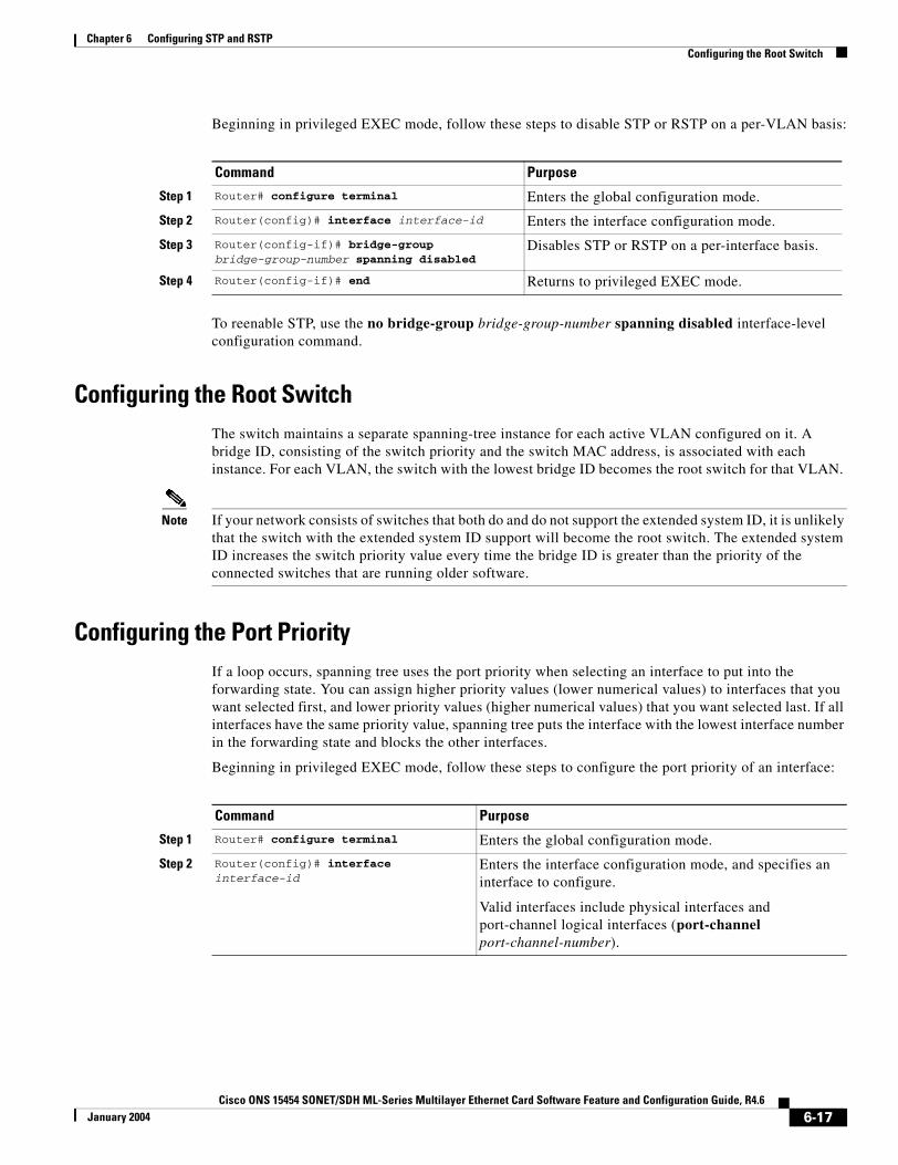
Chapter 6 Configuring STP and RSTPConfiguring the Root Switch
Beginning in privileged EXEC mode, follow these steps to disable STP or RSTP on a per-VLAN basis:
To reenable STP, use the no bridge-group bridge-group-number spanning disabled interface-level configuration command.
Configuring the Root SwitchThe switch maintains a separate spanning-tree instance for each active VLAN configured on it. A bridge ID, consisting of the switch priority and the switch MAC address, is associated with each instance. For each VLAN, the switch with the lowest bridge ID becomes the root switch for that VLAN.
Note If your network consists of switches that both do and do not support the extended system ID, it is unlikely that the switch with the extended system ID support will become the root switch. The extended system ID increases the switch priority value every time the bridge ID is greater than the priority of the connected switches that are running older software.
Configuring the Port PriorityIf a loop occurs, spanning tree uses the port priority when selecting an interface to put into the forwarding state. You can assign higher priority values (lower numerical values) to interfaces that you want selected first, and lower priority values (higher numerical values) that you want selected last. If all interfaces have the same priority value, spanning tree puts the interface with the lowest interface number in the forwarding state and blocks the other interfaces.
Beginning in privileged EXEC mode, follow these steps to configure the port priority of an interface:
Command Purpose
Step 1 Router# configure terminal Enters the global configuration mode.
Step 2 Router(config)# interface interface-id Enters the interface configuration mode.
Step 3 Router(config-if)# bridge-group bridge-group-number spanning disabled
Disables STP or RSTP on a per-interface basis.
Step 4 Router(config-if)# end Returns to privileged EXEC mode.
Command Purpose
Step 1 Router# configure terminal Enters the global configuration mode.
Step 2 Router(config)# interface interface-id
Enters the interface configuration mode, and specifies an interface to configure.
Valid interfaces include physical interfaces and port-channel logical interfaces (port-channel port-channel-number).
6-17Cisco ONS 15454 SONET/SDH ML-Series Multilayer Ethernet Card Software Feature and Configuration Guide, R4.6
January 2004

Chapter 6 Configuring STP and RSTPConfiguring the Path Cost
To return the interface to its default setting, use the no bridge-group id bridge-group-number priority- value command.
Configuring the Path CostThe spanning-tree path cost default value is derived from the media speed of an interface. If a loop occurs, spanning tree uses cost when selecting an interface to put in the forwarding state. You can assign lower cost values to interfaces that you want selected first and higher cost values to interfaces that you want selected last. If all interfaces have the same cost value, spanning tree puts the interface with the lowest interface number in the forwarding state and blocks the other interfaces.
Beginning in privileged EXEC mode, follow these steps to configure the cost of an interface:
Note The show spanning-tree interface interface-id privileged EXEC command displays information only for ports that are in a link-up operative state. Otherwise, you can use the show running-config privileged EXEC command to confirm the configuration.
To return the interface to its default setting, use the no bridge-group bridge-group-number path-cost cost command.
Step 3 Router(config-if)# bridge-group bridge-group-number priority-value
Configures the port priority for an interface that is an access port.
For the priority-value, the range is 0 to 255; the default is 128 in increments of 16. The lower the number, the higher the priority.
Step 4 Router(config-if)# end Return to privileged EXEC mode.
Command Purpose
Command Purpose
Step 1 Router# configure terminal Enters the global configuration mode.
Step 2 Router(config)# interface interface-id
Enters the interface configuration mode and specifies an interface to configure.
Valid interfaces include physical interfaces and port-channel logical interfaces (port-channel port-channel-number).
Step 3 Router(config-if)# bridge-group bridge-group-number path-cost cost
Configures the cost for an interface that is an access port.
If a loop occurs, spanning tree uses the path cost when selecting an interface to place into the forwarding state. A lower path cost represents higher-speed transmission.
For cost, the range is 0 to 65535; the default value is derived from the media speed of the interface.
Step 4 Router(config-if)# end Returns to the privileged EXEC mode.
6-18Cisco ONS 15454 SONET/SDH ML-Series Multilayer Ethernet Card Software Feature and Configuration Guide, R4.6
January 2004
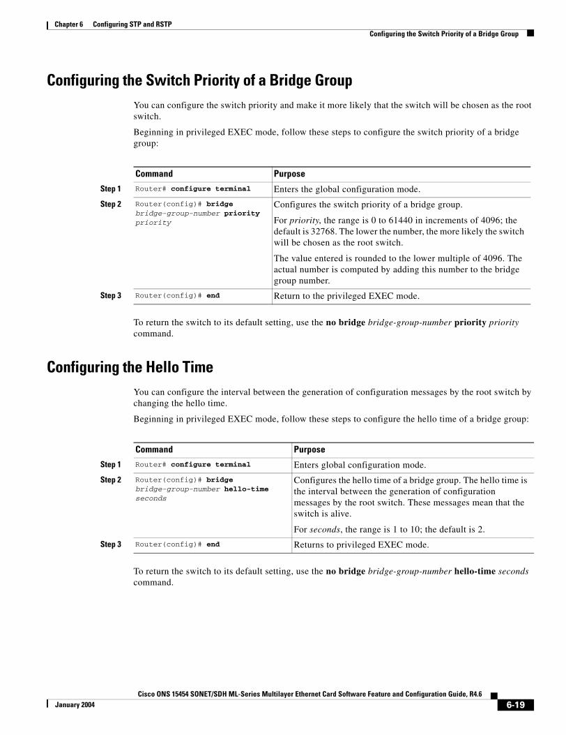
Chapter 6 Configuring STP and RSTPConfiguring the Switch Priority of a Bridge Group
Configuring the Switch Priority of a Bridge GroupYou can configure the switch priority and make it more likely that the switch will be chosen as the root switch.
Beginning in privileged EXEC mode, follow these steps to configure the switch priority of a bridge group:
To return the switch to its default setting, use the no bridge bridge-group-number priority priority command.
Configuring the Hello TimeYou can configure the interval between the generation of configuration messages by the root switch by changing the hello time.
Beginning in privileged EXEC mode, follow these steps to configure the hello time of a bridge group:
To return the switch to its default setting, use the no bridge bridge-group-number hello-time seconds command.
Command Purpose
Step 1 Router# configure terminal Enters the global configuration mode.
Step 2 Router(config)# bridge bridge-group-number priority priority
Configures the switch priority of a bridge group.
For priority, the range is 0 to 61440 in increments of 4096; the default is 32768. The lower the number, the more likely the switch will be chosen as the root switch.
The value entered is rounded to the lower multiple of 4096. The actual number is computed by adding this number to the bridge group number.
Step 3 Router(config)# end Return to the privileged EXEC mode.
Command Purpose
Step 1 Router# configure terminal Enters global configuration mode.
Step 2 Router(config)# bridge bridge-group-number hello-time seconds
Configures the hello time of a bridge group. The hello time is the interval between the generation of configuration messages by the root switch. These messages mean that the switch is alive.
For seconds, the range is 1 to 10; the default is 2.
Step 3 Router(config)# end Returns to privileged EXEC mode.
6-19Cisco ONS 15454 SONET/SDH ML-Series Multilayer Ethernet Card Software Feature and Configuration Guide, R4.6
January 2004
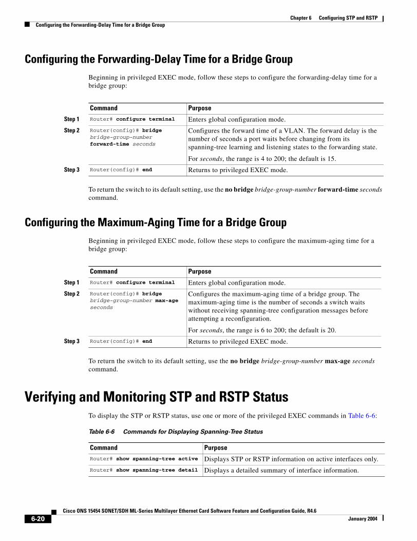
Chapter 6 Configuring STP and RSTPConfiguring the Forwarding-Delay Time for a Bridge Group
Configuring the Forwarding-Delay Time for a Bridge GroupBeginning in privileged EXEC mode, follow these steps to configure the forwarding-delay time for a bridge group:
To return the switch to its default setting, use the no bridge bridge-group-number forward-time seconds command.
Configuring the Maximum-Aging Time for a Bridge GroupBeginning in privileged EXEC mode, follow these steps to configure the maximum-aging time for a bridge group:
To return the switch to its default setting, use the no bridge bridge-group-number max-age seconds command.
Verifying and Monitoring STP and RSTP StatusTo display the STP or RSTP status, use one or more of the privileged EXEC commands in Table 6-6:
Command Purpose
Step 1 Router# configure terminal Enters global configuration mode.
Step 2 Router(config)# bridge bridge-group-number forward-time seconds
Configures the forward time of a VLAN. The forward delay is the number of seconds a port waits before changing from its spanning-tree learning and listening states to the forwarding state.
For seconds, the range is 4 to 200; the default is 15.
Step 3 Router(config)# end Returns to privileged EXEC mode.
Command Purpose
Step 1 Router# configure terminal Enters global configuration mode.
Step 2 Router(config)# bridge bridge-group-number max-age seconds
Configures the maximum-aging time of a bridge group. The maximum-aging time is the number of seconds a switch waits without receiving spanning-tree configuration messages before attempting a reconfiguration.
For seconds, the range is 6 to 200; the default is 20.
Step 3 Router(config)# end Returns to privileged EXEC mode.
Table 6-6 Commands for Displaying Spanning-Tree Status
Command Purpose
Router# show spanning-tree active Displays STP or RSTP information on active interfaces only.
Router# show spanning-tree detail Displays a detailed summary of interface information.
6-20Cisco ONS 15454 SONET/SDH ML-Series Multilayer Ethernet Card Software Feature and Configuration Guide, R4.6
January 2004
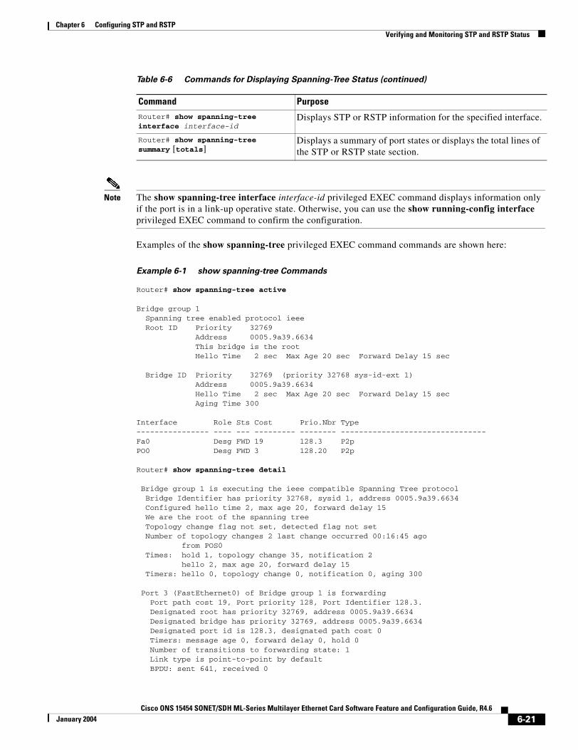
Chapter 6 Configuring STP and RSTPVerifying and Monitoring STP and RSTP Status
Note The show spanning-tree interface interface-id privileged EXEC command displays information only if the port is in a link-up operative state. Otherwise, you can use the show running-config interface privileged EXEC command to confirm the configuration.
Examples of the show spanning-tree privileged EXEC command commands are shown here:
Example 6-1 show spanning-tree Commands
Router# show spanning-tree active
Bridge group 1 Spanning tree enabled protocol ieee Root ID Priority 32769 Address 0005.9a39.6634 This bridge is the root Hello Time 2 sec Max Age 20 sec Forward Delay 15 sec
Bridge ID Priority 32769 (priority 32768 sys-id-ext 1) Address 0005.9a39.6634 Hello Time 2 sec Max Age 20 sec Forward Delay 15 sec Aging Time 300
Interface Role Sts Cost Prio.Nbr Type---------------- ---- --- --------- -------- --------------------------------Fa0 Desg FWD 19 128.3 P2p PO0 Desg FWD 3 128.20 P2p
Router# show spanning-tree detail
Bridge group 1 is executing the ieee compatible Spanning Tree protocol Bridge Identifier has priority 32768, sysid 1, address 0005.9a39.6634 Configured hello time 2, max age 20, forward delay 15 We are the root of the spanning tree Topology change flag not set, detected flag not set Number of topology changes 2 last change occurred 00:16:45 ago from POS0 Times: hold 1, topology change 35, notification 2 hello 2, max age 20, forward delay 15 Timers: hello 0, topology change 0, notification 0, aging 300
Port 3 (FastEthernet0) of Bridge group 1 is forwarding Port path cost 19, Port priority 128, Port Identifier 128.3. Designated root has priority 32769, address 0005.9a39.6634 Designated bridge has priority 32769, address 0005.9a39.6634 Designated port id is 128.3, designated path cost 0 Timers: message age 0, forward delay 0, hold 0 Number of transitions to forwarding state: 1 Link type is point-to-point by default BPDU: sent 641, received 0
Router# show spanning-tree interface interface-id
Displays STP or RSTP information for the specified interface.
Router# show spanning-tree summary [totals]
Displays a summary of port states or displays the total lines of the STP or RSTP state section.
Table 6-6 Commands for Displaying Spanning-Tree Status (continued)
Command Purpose
6-21Cisco ONS 15454 SONET/SDH ML-Series Multilayer Ethernet Card Software Feature and Configuration Guide, R4.6
January 2004

Chapter 6 Configuring STP and RSTPVerifying and Monitoring STP and RSTP Status
Port 20 (POS0) of Bridge group 1 is forwarding Port path cost 3, Port priority 128, Port Identifier 128.20. Designated root has priority 32769, address 0005.9a39.6634 Designated bridge has priority 32769, address 0005.9a39.6634 Designated port id is 128.20, designated path cost 0 Timers: message age 0, forward delay 0, hold 0 Number of transitions to forwarding state: 6 Link type is point-to-point by default BPDU: sent 582, received 15
Router# show spanning-tree interface fast 0
Bridge Group Role Sts Cost Prio.Nbr Type---------------- ---- --- --------- -------- --------------------------------Bridge group 1 Desg FWD 19 128.3 P2p
Router# show spanning-tree interface pos 0
Bridge Group Role Sts Cost Prio.Nbr Type---------------- ---- --- --------- -------- --------------------------------Bridge group 1 Desg FWD 3 128.20 P2p
Router# show spanning-tree summary totalsSwitch is in pvst modeRoot bridge for: Bridge group 1
Name Blocking Listening Learning Forwarding STP Active---------------------- -------- --------- -------- ---------- ----------1 bridge 0 0 0 2 2
6-22Cisco ONS 15454 SONET/SDH ML-Series Multilayer Ethernet Card Software Feature and Configuration Guide, R4.6
January 2004
Cisco ONS 15454 SONET/SDH ML-Series Multilayer Ethernet Card SoftwarJanuary 2004
C H A P T E R 7
Configuring VLANsThis chapter describes VLAN configurations for the ML-Series card. It describes how to configure IEEE 802.1Q VLAN encapsulation. For more information about the Cisco IOS commands used in this chapter, refer to the Cisco IOS Command Reference publication.
This chapter contains the following major sections:
• Understanding VLANs, page 7-1
• Configuring IEEE 802.1Q VLAN Encapsulation, page 7-2
• IEEE 802.1Q VLAN Configuration, page 7-3
• Monitoring and Verifying VLAN Operation, page 7-5
Note Configuring VLANs is optional. Complete general interface configurations before proceeding with configuring VLANs as an optional step.
Understanding VLANsVLANs enable network managers to group users logically rather than by physical location. A VLAN is an emulation of a standard LAN that allows secure intragroup data transfer and communication to occur without the traditional restraints placed on the network. It can also be considered a broadcast domain set up within a switch. With VLANs, switches can support more than one subnet (or VLAN) on each switch and give routers and switches the opportunity to support multiple subnets on a single physical link. A group of devices that belong to the same VLAN, but are part of different LAN segments, are configured to communicate as if they were part of the same LAN segment.
VLANs enable efficient traffic separation and provide excellent bandwidth utilization. VLANs also alleviate scaling issues by logically segmenting the physical LAN structure into different subnetworks so that packets are switched only between ports within the same VLAN. This can be very useful for security, broadcast containment, and accounting.
ML-Series software supports port-based VLANs and VLAN trunk ports, which are ports that carry the traffic of multiple VLANs. Each frame transmitted on a trunk link is tagged as belonging to only one VLAN.
ML-Series software supports VLAN frame encapsulation through the IEEE 802.1Q standard on both the ML100T-12 and the ML1000-2. The Cisco Inter-Switch Link (ISL) VLAN frame encapsulation is not supported. ISL frames are broadcast at Layer 2 or dropped at Layer 3.
7-1e Feature and Configuration Guide, R4.6
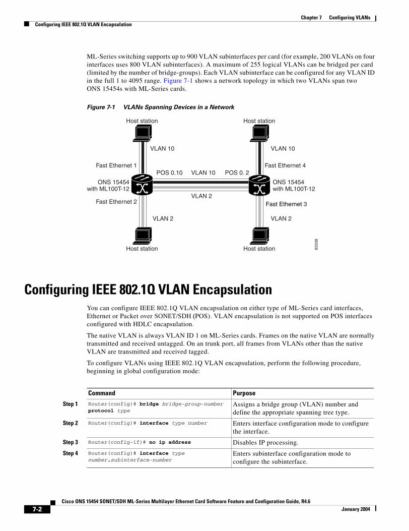
Chapter 7 Configuring VLANsConfiguring IEEE 802.1Q VLAN Encapsulation
ML-Series switching supports up to 900 VLAN subinterfaces per card (for example, 200 VLANs on four interfaces uses 800 VLAN subinterfaces). A maximum of 255 logical VLANs can be bridged per card (limited by the number of bridge-groups). Each VLAN subinterface can be configured for any VLAN ID in the full 1 to 4095 range. Figure 7-1 shows a network topology in which two VLANs span two ONS 15454s with ML-Series cards.
Figure 7-1 VLANs Spanning Devices in a Network
Configuring IEEE 802.1Q VLAN EncapsulationYou can configure IEEE 802.1Q VLAN encapsulation on either type of ML-Series card interfaces, Ethernet or Packet over SONET/SDH (POS). VLAN encapsulation is not supported on POS interfaces configured with HDLC encapsulation.
The native VLAN is always VLAN ID 1 on ML-Series cards. Frames on the native VLAN are normally transmitted and received untagged. On an trunk port, all frames from VLANs other than the native VLAN are transmitted and received tagged.
To configure VLANs using IEEE 802.1Q VLAN encapsulation, perform the following procedure, beginning in global configuration mode:
Host station
Host station
Host station
Host station
VLAN 10
VLAN 10
VLAN 2
VLAN 10
VLAN 2 VLAN 2
Fast Ethernet 3
ONS 15454with ML100T-12
ONS 15454with ML100T-12
8333
8
Fast Ethernet 1 Fast Ethernet 4POS 0.10 POS 0. 2
Fast Ethernet 2
Command Purpose
Step 1 Router(config)# bridge bridge-group-number protocol type
Assigns a bridge group (VLAN) number and define the appropriate spanning tree type.
Step 2 Router(config)# interface type number Enters interface configuration mode to configure the interface.
Step 3 Router(config-if)# no ip address Disables IP processing.
Step 4 Router(config)# interface type number.subinterface-number
Enters subinterface configuration mode to configure the subinterface.
7-2Cisco ONS 15454 SONET/SDH ML-Series Multilayer Ethernet Card Software Feature and Configuration Guide, R4.6
January 2004
Chapter 7 Configuring VLANsIEEE 802.1Q VLAN Configuration
Note In a bridge group on the ML-Series card, the VLAN ID does not have to be uniform across interfaces that belong to that bridge group. For example, a bridge-group can connect from a VLAN ID subinterface to a subinterface with a different VLAN ID, and then frames entering with one VLAN ID can be changed to exit with a different VLAN ID. This is know as VLAN translation.
Note IP routing is enabled by default. To enable bridging, enter the no ip routing or bridge IRB command.
Note Native VLAN frames transmitted on the interface are normally untagged. All untagged frames received on the interface are associated with the native VLAN, which is always VLAN 1. Use the command encapsulation dot1q 1 native.
IEEE 802.1Q VLAN Configuration The VLAN configuration example for the ML100T-12 shown in Figure 7-2 depicts the following VLANs:
• Fast Ethernet subinterface 0.1 is in the IEEE 802.1Q native VLAN 1.
• Fast Ethernet subinterface 0.2 is in the IEEE 802.1Q VLAN 2.
• Fast Ethernet subinterface 0.3 is in the IEEE 802.1Q VLAN 3.
• Fast Ethernet subinterface 0.4 is in the IEEE 802.1Q VLAN 4.
Step 5 Router(config-subif)# encap dot1q vlan-number
Sets the encapsulation on the VLAN to IEEE 802.1Q.
Step 6 Router(config-subif)# bridge-group bridge-group-number
Assigns a network interface to a bridge group.
Step 7 Router(config-subif)# end Returns to privileged EXEC mode.
Step 8 Router# copy running-config startup-config (Optional) Saves your configuration changes to NVRAM.
Command Purpose
7-3Cisco ONS 15454 SONET/SDH ML-Series Multilayer Ethernet Card Software Feature and Configuration Guide, R4.6
January 2004
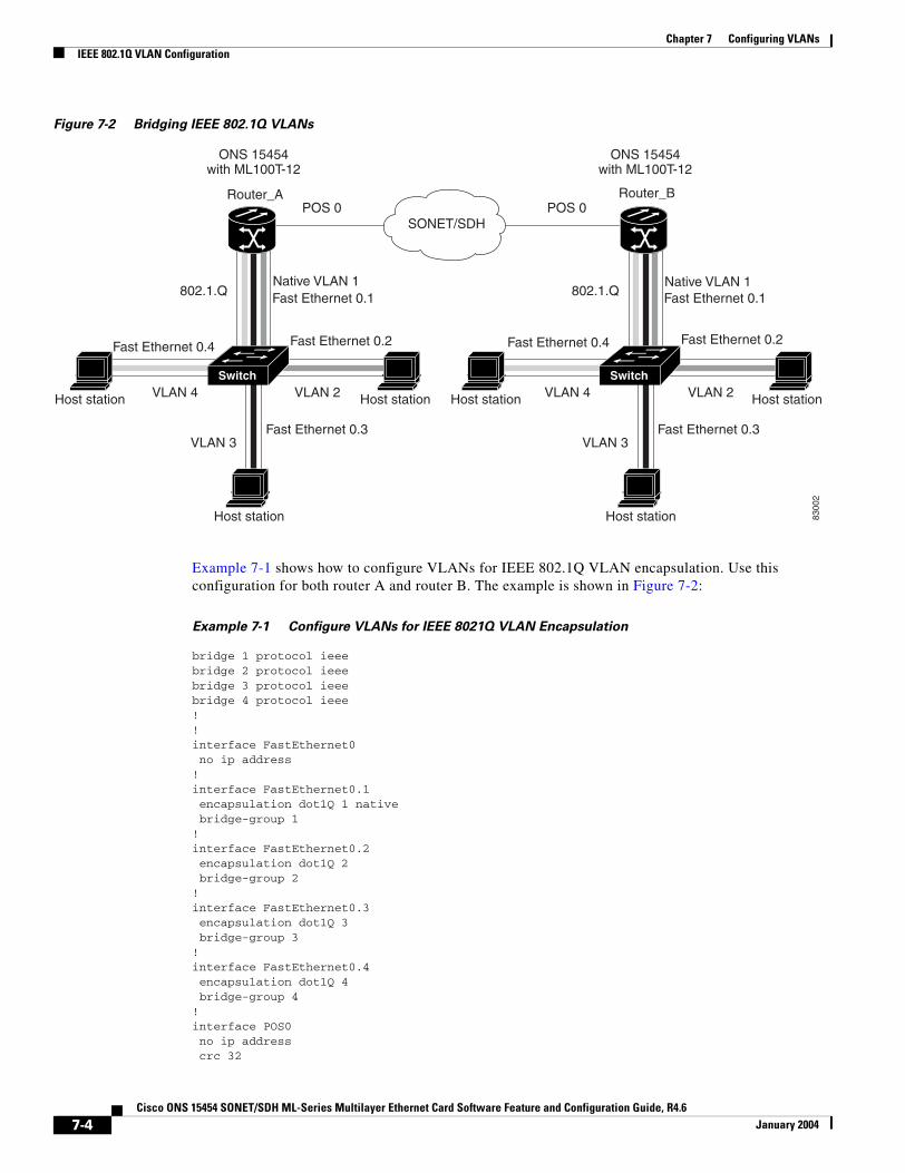
Chapter 7 Configuring VLANsIEEE 802.1Q VLAN Configuration
Figure 7-2 Bridging IEEE 802.1Q VLANs
Example 7-1 shows how to configure VLANs for IEEE 802.1Q VLAN encapsulation. Use this configuration for both router A and router B. The example is shown in Figure 7-2:
Example 7-1 Configure VLANs for IEEE 8021Q VLAN Encapsulation
bridge 1 protocol ieeebridge 2 protocol ieeebridge 3 protocol ieeebridge 4 protocol ieee!!interface FastEthernet0 no ip address!interface FastEthernet0.1 encapsulation dot1Q 1 native bridge-group 1!interface FastEthernet0.2 encapsulation dot1Q 2 bridge-group 2!interface FastEthernet0.3 encapsulation dot1Q 3 bridge-group 3!interface FastEthernet0.4 encapsulation dot1Q 4 bridge-group 4!interface POS0 no ip address crc 32
ONS 15454with ML100T-12
ONS 15454with ML100T-12
POS 0POS 0Router_A Router_B
8300
2
SONET/SDH
Fast Ethernet 0.1
Host station
VLAN 2Host station Host station
VLAN 3
VLAN 4
Fast Ethernet 0.3
Fast Ethernet 0.2Fast Ethernet 0.4
Switch
802.1.Q Fast Ethernet 0.1
Host station
VLAN 2Host station Host station
VLAN 3
VLAN 4
Fast Ethernet 0.3
Fast Ethernet 0.2Fast Ethernet 0.4
Switch
802.1.QNative VLAN 1 Native VLAN 1
7-4Cisco ONS 15454 SONET/SDH ML-Series Multilayer Ethernet Card Software Feature and Configuration Guide, R4.6
January 2004
Chapter 7 Configuring VLANsMonitoring and Verifying VLAN Operation
pos flag c2 1!interface POS0.1 encapsulation dot1Q 1 native bridge-group 1!interface POS0.2 encapsulation dot1Q 2 bridge-group 2!interface POS0.3 encapsulation dot1Q 3 bridge-group 3!interface POS0.4 encapsulation dot1Q 4 bridge-group 4
Monitoring and Verifying VLAN OperationAfter the VLANs are configured on the ML-Series card, you can monitor their operation by entering the privileged EXEC command show vlans vlan-id. This command displays information on all configured VLANs or on a specific VLAN (by VLAN ID number).
Caution Two similar commands exist. The command show vlans gives information regarding IEEE 802.1Q VLANs configured on the ML-Series card. The command show vlan gives information regarding the VLAN tunnel. For more information on VLAN tunneling, see Chapter 8, “Configuring IEEE 802.1Q and Layer 2 Protocol Tunneling.”
7-5Cisco ONS 15454 SONET/SDH ML-Series Multilayer Ethernet Card Software Feature and Configuration Guide, R4.6
January 2004

Chapter 7 Configuring VLANsMonitoring and Verifying VLAN Operation
7-6Cisco ONS 15454 SONET/SDH ML-Series Multilayer Ethernet Card Software Feature and Configuration Guide, R4.6
January 2004

Cisco ONS 15454 SONET/SDH ML-Series Multilayer Ethernet Card SoftwarJanuary 2004
C H A P T E R 8
Configuring IEEE 802.1Q and Layer 2 Protocol TunnelingVirtual private networks (VPNs) provide enterprise-scale connectivity on a shared infrastructure, often Ethernet-based, with the same security, prioritization, reliability, and manageability requirements of private networks. Tunneling is a feature designed for service providers who carry traffic of multiple customers across their networks and are required to maintain the VLAN and Layer 2 protocol configurations of each customer without impacting the traffic of other customers. The ML-Series cards support IEEE 802.1Q tunneling and Layer 2 protocol tunneling.
This chapter contains the following sections:
• Understanding IEEE 802.1Q Tunneling, page 8-1
• Configuring IEEE 802.1Q Tunneling, page 8-4
• Understanding VLAN-Transparent and VLAN-Specific Services, page 8-7
• Understanding Layer 2 Protocol Tunneling, page 8-10
• Configuring Layer 2 Protocol Tunneling, page 8-10
Understanding IEEE 802.1Q TunnelingBusiness customers of service providers often have specific requirements for VLAN IDs and the number of VLANs to be supported. The VLAN ranges required by different customers in the same service-provider network might overlap, and traffic of customers through the infrastructure might be mixed. Assigning a unique range of VLAN IDs to each customer would restrict customer configurations and could easily exceed the IEEE 802.1Q specification VLAN limit of 4096.
Using the IEEE 802.1Q tunneling (QinQ) feature, service providers can use a single VLAN to support customers who have multiple VLANs. Customer VLAN IDs are preserved and traffic from different customers is segregated within the service-provider infrastructure even when they appear to be on the same VLAN. The IEEE 802.1Q tunneling expands VLAN space by using a VLAN-in-VLAN hierarchy and tagging the tagged packets. A port configured to support IEEE 802.1Q tunneling is called a tunnel port. When you configure tunneling, you assign a tunnel port to a VLAN that is dedicated to tunneling. Each customer requires a separate VLAN, but that VLAN supports all of the customer’s VLANs.
Customer traffic tagged in the normal way with appropriate VLAN IDs comes from an IEEE 802.1Q trunk port on the customer device and into a tunnel port on the ML-Series card. The link between the customer device and the ML-Series card is an asymmetric link because one end is configured as an IEEE 802.1Q trunk port and the other end is configured as a tunnel port. You assign the tunnel port interface to an access VLAN ID unique to each customer (Figure 8-1).
8-1e Feature and Configuration Guide, R4.6
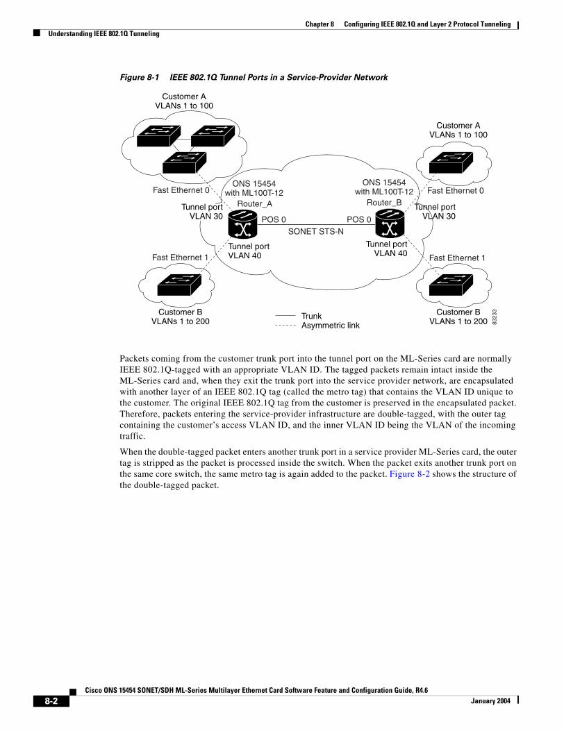
Chapter 8 Configuring IEEE 802.1Q and Layer 2 Protocol TunnelingUnderstanding IEEE 802.1Q Tunneling
Figure 8-1 IEEE 802.1Q Tunnel Ports in a Service-Provider Network
Packets coming from the customer trunk port into the tunnel port on the ML-Series card are normally IEEE 802.1Q-tagged with an appropriate VLAN ID. The tagged packets remain intact inside the ML-Series card and, when they exit the trunk port into the service provider network, are encapsulated with another layer of an IEEE 802.1Q tag (called the metro tag) that contains the VLAN ID unique to the customer. The original IEEE 802.1Q tag from the customer is preserved in the encapsulated packet. Therefore, packets entering the service-provider infrastructure are double-tagged, with the outer tag containing the customer’s access VLAN ID, and the inner VLAN ID being the VLAN of the incoming traffic.
When the double-tagged packet enters another trunk port in a service provider ML-Series card, the outer tag is stripped as the packet is processed inside the switch. When the packet exits another trunk port on the same core switch, the same metro tag is again added to the packet. Figure 8-2 shows the structure of the double-tagged packet.
Customer AVLANs 1 to 100
Customer BVLANs 1 to 200
Customer BVLANs 1 to 200
Customer AVLANs 1 to 100
Tunnel portVLAN 40
Tunnel portVLAN 40
TrunkAsymmetric link
Tunnel portVLAN 30
ONS 15454with ML100T-12
POS 0POS 0
Router_A
SONET STS-N
ONS 15454with ML100T-12
Router_B
Fast Ethernet 1
Fast Ethernet 0
Fast Ethernet 1
Fast Ethernet 0
8323
3
Tunnel portVLAN 30
8-2Cisco ONS 15454 SONET/SDH ML-Series Multilayer Ethernet Card Software Feature and Configuration Guide, R4.6
January 2004
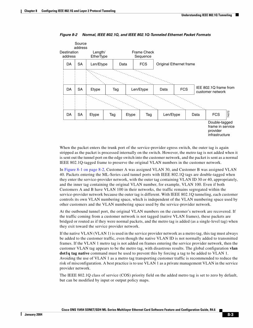
Chapter 8 Configuring IEEE 802.1Q and Layer 2 Protocol TunnelingUnderstanding IEEE 802.1Q Tunneling
Figure 8-2 Normal, IEEE 802.1Q, and IEEE 802.1Q-Tunneled Ethernet Packet Formats
When the packet enters the trunk port of the service-provider egress switch, the outer tag is again stripped as the packet is processed internally on the switch. However, the metro tag is not added when it is sent out the tunnel port on the edge switch into the customer network, and the packet is sent as a normal IEEE 802.1Q-tagged frame to preserve the original VLAN numbers in the customer network.
In Figure 8-1 on page 8-2, Customer A was assigned VLAN 30, and Customer B was assigned VLAN 40. Packets entering the ML-Series card tunnel ports with IEEE 802.1Q tags are double-tagged when they enter the service-provider network, with the outer tag containing VLAN ID 30 or 40, appropriately, and the inner tag containing the original VLAN number, for example, VLAN 100. Even if both Customers A and B have VLAN 100 in their networks, the traffic remains segregated within the service-provider network because the outer tag is different. With IEEE 802.1Q tunneling, each customer controls its own VLAN numbering space, which is independent of the VLAN numbering space used by other customers and the VLAN numbering space used by the service-provider network.
At the outbound tunnel port, the original VLAN numbers on the customer’s network are recovered. If the traffic coming from a customer network is not tagged (native VLAN frames), these packets are bridged or routed as if they were normal packets, and the metro tag is added (as a single-level tag) when they exit toward the service provider network.
If the native VLAN (VLAN 1) is used in the service provider network as a metro tag, this tag must always be added to the customer traffic, even though the native VLAN ID is not normally added to transmitted frames. If the VLAN 1 metro tag is not added on frames entering the service provider network, then the customer VLAN tag appears to be the metro tag, with disastrous results. The global configuration vlan dot1q tag native command must be used to prevent this by forcing a tag to be added to VLAN 1. Avoiding the use of VLAN 1 as a metro tag transporting customer traffic is recommended to reduce the risk of misconfiguration. A best practice is to use VLAN 1 as a private management VLAN in the service provider network.
The IEEE 802.1Q class of service (COS) priority field on the added metro tag is set to zero by default, but can be modified by input or output policy maps.
Double-taggedframe in serviceproviderinfrastructure
IEE 802.1Q frame fromcustomer network
Original Ethernet frame
Destinationaddress
Length/EtherType
Frame CheckSequence
Sourceaddress
SADA Len/Etype Data FCS
SADA Len/Etype DataEtype Tag FCS
SADA Len/Etype DataEtype Tag Etype Tag FCS
7407
2
8-3Cisco ONS 15454 SONET/SDH ML-Series Multilayer Ethernet Card Software Feature and Configuration Guide, R4.6
January 2004
Chapter 8 Configuring IEEE 802.1Q and Layer 2 Protocol TunnelingConfiguring IEEE 802.1Q Tunneling
Configuring IEEE 802.1Q TunnelingThis section includes the following information about configuring IEEE 802.1Q tunneling:
• IEEE 802.1Q Tunneling and Compatibility with Other Features, page 8-4
• Configuring an IEEE 802.1Q Tunneling Port, page 8-4
• IEEE 802.1Q Example, page 8-5
Note By default, IEEE 802.1Q tunneling is not configured on the ML-Series.
IEEE 802.1Q Tunneling and Compatibility with Other FeaturesAlthough IEEE 802.1Q tunneling works well for Layer 2 packet switching, there are incompatibilities with some Layer 2 features and with Layer 3 switching:
• A tunnel port cannot be a routed port.
• Tunnel ports do not support IP access control lists (ACLs).
• Layer 3 quality of service (QoS) ACLs and other QoS features related to Layer 3 information are not supported on tunnel ports. MAC-based QoS is supported on tunnel ports.
• EtherChannel port groups are compatible with tunnel ports as long as the IEEE 802.1Q configuration is consistent within an EtherChannel port group.
• Port Aggregation Protocol (PAgP) and Unidirectional Link Detection (UDLD) Protocol are not supported on IEEE 802.1Q tunnel ports.
• Dynamic Trunking Protocol (DTP) is not compatible with IEEE 802.1Q tunneling because you must manually configure asymmetric links with tunnel ports and trunk ports.
• Loopback detection is supported on IEEE 802.1Q tunnel ports.
• When a port is configured as an IEEE 802.1Q tunnel port, spanning tree bridge protocol data unit (BPDU) filtering is automatically disabled on the interface.
Configuring an IEEE 802.1Q Tunneling PortBeginning in privileged EXEC mode, follow these steps to configure a port as an IEEE 802.1Q tunnel port:
Command Purpose
Step 1 Router# configure terminal Enters global configuration mode.
Step 2 Router(config)# bridge bridge-number protocol bridge-protocol
Creates a bridge number and specifies a protocol.
Step 3 Router(config)# interface fastEthernet number
Enters the interface configuration mode and the interface to be configured as a tunnel port. This should be the edge port in the service-provider network that connects to the customer switch. Valid interfaces include physical interfaces and port-channel logical interfaces (port channels 1 to 64).
8-4Cisco ONS 15454 SONET/SDH ML-Series Multilayer Ethernet Card Software Feature and Configuration Guide, R4.6
January 2004
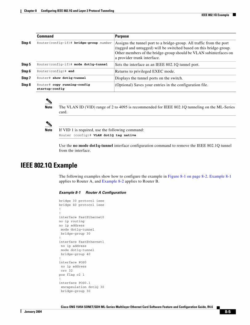
Chapter 8 Configuring IEEE 802.1Q and Layer 2 Protocol TunnelingIEEE 802.1Q Example
Note The VLAN ID (VID) range of 2 to 4095 is recommended for IEEE 802.1Q tunneling on the ML-Series card.
Note If VID 1 is required, use the following command: Router (config)# VLAN dot1Q tag native
Use the no mode dot1q-tunnel interface configuration command to remove the IEEE 802.1Q tunnel from the interface.
IEEE 802.1Q ExampleThe following examples show how to configure the example in Figure 8-1 on page 8-2. Example 8-1 applies to Router A, and Example 8-2 applies to Router B.
Example 8-1 Router A Configuration
bridge 30 protocol ieeebridge 40 protocol ieee!!interface FastEthernet0no ip routingno ip address mode dot1q-tunnel bridge-group 30!interface FastEthernet1 no ip address mode dot1q-tunnel bridge-group 40!interface POS0 no ip address crc 32pos flag c2 1!interface POS0.1 encapsulation dot1Q 30 bridge-group 30
Step 4 Router(config-if)# bridge-group number Assigns the tunnel port to a bridge-group. All traffic from the port (tagged and untagged) will be switched based on this bridge-group. Other members of the bridge-group should be VLAN subinterfaces on a provider trunk interface.
Step 5 Router(config-if)# mode dot1q-tunnel Sets the interface as an IEEE 802.1Q tunnel port.
Step 6 Router(config)# end Returns to privileged EXEC mode.
Step 7 Router# show dot1q-tunnel Displays the tunnel ports on the switch.
Step 8 Router# copy running-config startup-config
(Optional) Saves your entries in the configuration file.
Command Purpose
8-5Cisco ONS 15454 SONET/SDH ML-Series Multilayer Ethernet Card Software Feature and Configuration Guide, R4.6
January 2004
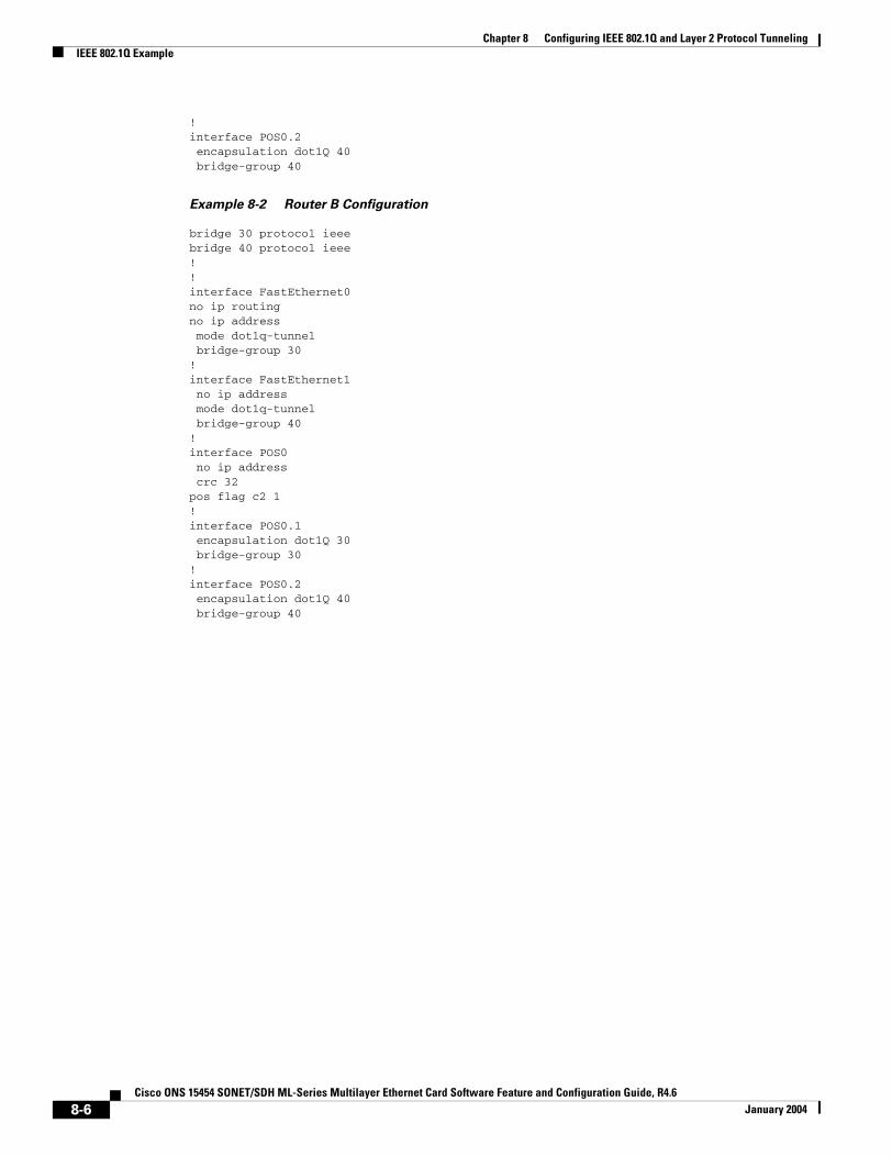
Chapter 8 Configuring IEEE 802.1Q and Layer 2 Protocol TunnelingIEEE 802.1Q Example
!interface POS0.2 encapsulation dot1Q 40 bridge-group 40
Example 8-2 Router B Configuration
bridge 30 protocol ieeebridge 40 protocol ieee!!interface FastEthernet0no ip routingno ip address mode dot1q-tunnel bridge-group 30!interface FastEthernet1 no ip address mode dot1q-tunnel bridge-group 40!interface POS0 no ip address crc 32pos flag c2 1!interface POS0.1 encapsulation dot1Q 30 bridge-group 30!interface POS0.2 encapsulation dot1Q 40 bridge-group 40
8-6Cisco ONS 15454 SONET/SDH ML-Series Multilayer Ethernet Card Software Feature and Configuration Guide, R4.6
January 2004
Chapter 8 Configuring IEEE 802.1Q and Layer 2 Protocol TunnelingUnderstanding VLAN-Transparent and VLAN-Specific Services
Understanding VLAN-Transparent and VLAN-Specific ServicesIn Software Release 4.6 and later, the ML-Series card supports combining VLAN-transparent services and one or more VLAN-specific services on the same port. All of these VLAN-transparent and VLAN-specific services can be point-to-point or multipoint-to-multipoint.
This allows a service provider to combine a VLAN-transparent service, such as IEE 802.1Q tunneling (QinQ), with VLAN-specific services, such as bridging specific VLANs, on the same customer port. For example, one customer VLAN can connect to Internet access and the other customer VLANs can be tunneled over a single provider VLAN to another customer site, all over a single port at each site. Table 8-1 outlines the differences between VLAN-transparent and VLAN-specific services.
Note VLAN-transparent service is also referred to as Ethernet Wire Service (EWS). VLAN-specific service is also referred to as Ethernet Relay Multipoint Service (ERMS).
A VLAN-specific service on a subinterface coexists with the VLAN-transparent service, often IEEE 802.1Q tunneling, on a physical interface. VLANs configured for a VLAN-transparent service and a VLAN-specific service follow the VLAN-specific service configuration. If you need to configure 802.1Q tunneling, configure this VLAN-transparent service in the normal manner, see the “Configuring IEEE 802.1Q Tunneling” section on page 8-4.
A VLAN-specific service can be any service normally applicable to a VLAN. To configure an ERMS VLAN-specific service, configure the service in the normal manner.
VLAN-Transparent and VLAN-Specific Services Configuration Example
In this example, the Gigabit Ethernet interface 0 on both the ML-Series card A and ML-Series card C are the trunk ports in an IEEE 802.1Q tunnel, a VLAN-transparent service. VLAN 10 is used for the VLAN-transparent service, which would normally transport all customer VLANs on the ML-Series card A’s Gigabit Ethernet interface 0. All unspecified VLANs and VLAN 1 would also be tunneled across VLAN 10.
VLAN 30 is prevented from entering the VLAN-transparent service and is instead forwarded on a specific-VLAN service, bridging Gigabit Ethernet interface 0 on ML-Series card A and Gigabit Ethernet interface 0 on ML-Series card B. Figure 8-3 is used as an example to performing configuration examples 8-3, 8-4, and 8-6.
Table 8-1 VLAN-Transparent Service Versus VLAN-Specific Services
VLAN-Transparent Services VLAN-Specific Services
Bridging only Bridging or routing
One service per port Up to 254 VLAN-specific services per port
Applies indiscriminately to all VLANs on the physical interface
Applies only to specified VLANs
8-7Cisco ONS 15454 SONET/SDH ML-Series Multilayer Ethernet Card Software Feature and Configuration Guide, R4.6
January 2004
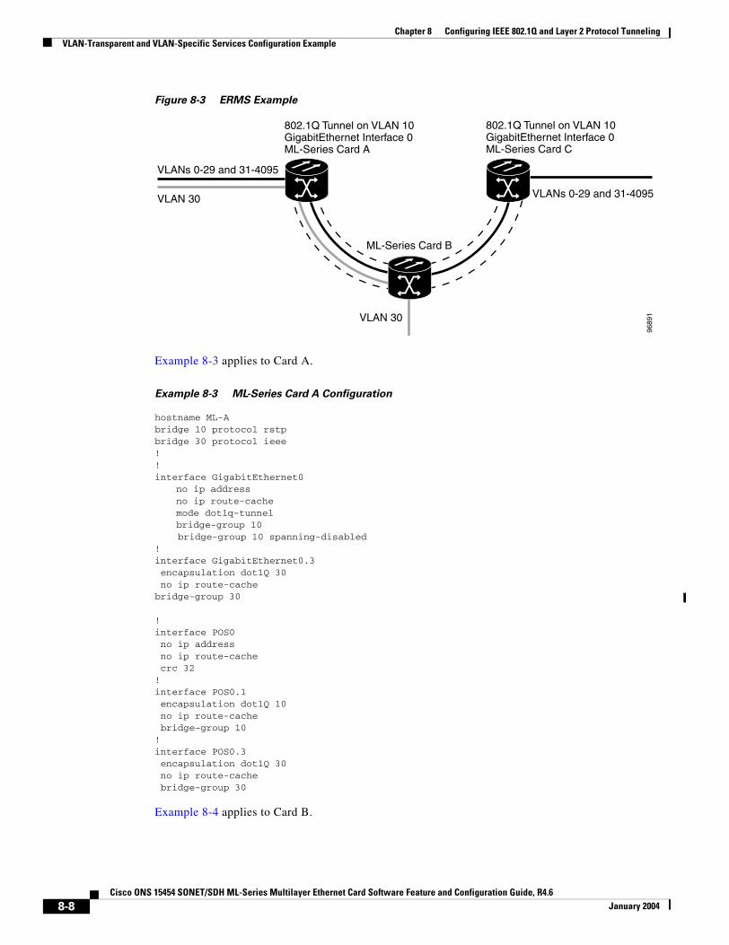
Chapter 8 Configuring IEEE 802.1Q and Layer 2 Protocol TunnelingVLAN-Transparent and VLAN-Specific Services Configuration Example
Figure 8-3 ERMS Example
Example 8-3 applies to Card A.
Example 8-3 ML-Series Card A Configuration
hostname ML-Abridge 10 protocol rstpbridge 30 protocol ieee!!interface GigabitEthernet0
no ip addressno ip route-cachemode dot1q-tunnelbridge-group 10 bridge-group 10 spanning-disabled
!interface GigabitEthernet0.3 encapsulation dot1Q 30 no ip route-cachebridge-group 30
!interface POS0 no ip address no ip route-cache crc 32!interface POS0.1 encapsulation dot1Q 10 no ip route-cache bridge-group 10!interface POS0.3 encapsulation dot1Q 30 no ip route-cache bridge-group 30
Example 8-4 applies to Card B.
802.1Q Tunnel on VLAN 10GigabitEthernet Interface 0ML-Series Card A
VLAN 30
ML-Series Card B
9689
1
VLAN 30
VLANs 0-29 and 31-4095
VLANs 0-29 and 31-4095
802.1Q Tunnel on VLAN 10GigabitEthernet Interface 0ML-Series Card C
8-8Cisco ONS 15454 SONET/SDH ML-Series Multilayer Ethernet Card Software Feature and Configuration Guide, R4.6
January 2004

Chapter 8 Configuring IEEE 802.1Q and Layer 2 Protocol TunnelingVLAN-Transparent and VLAN-Specific Services Configuration Example
Example 8-4 ML-Series Card B Configuration
Example 8-4 applies to Card B.
Example 8-5 ML-Series Card B Configuration
hostname ML-B!bridge 10 protocol rstpbridge 30 protocol ieee!!interface GigabitEthernet0 no ip address!interface GigabitEthernet0.3 encapsulation dot1Q 30 bridge-group 30!interface GigabitEthernet1 no ip address shutdown!interface POS0 no ip address crc 32!interface POS0.1 encapsulation dot1Q 10 bridge-group 10!interface POS0.3 encapsulation dot1Q 30 bridge-group 30!interface POS1 no ip address crc 32!interface POS1.1 encapsulation dot1Q 10 bridge-group 10!interface POS1.3 encapsulation dot1Q 30 bridge-group 30
Example 8-6 applies to Card C.
Example 8-6 ML-Series Card C Configuration
hostname ML-Cbridge 10 protocol rstp!!interface GigabitEthernet0
no ip addressno ip route-cachemode dot1q-tunnelbridge-group 10 bridge-group 10 spanning-disabled
!
8-9Cisco ONS 15454 SONET/SDH ML-Series Multilayer Ethernet Card Software Feature and Configuration Guide, R4.6
January 2004
Chapter 8 Configuring IEEE 802.1Q and Layer 2 Protocol TunnelingUnderstanding Layer 2 Protocol Tunneling
interface POS0 no ip address no ip route-cache crc 32!interface POS0.1 encapsulation dot1Q 10 no ip route-cache bridge-group 10
Understanding Layer 2 Protocol TunnelingCustomers at different sites connected across a service-provider network need to run various Layer 2 protocols to scale their topology to include all remote sites, as well as the local sites. Spanning Tree Protocol (STP) must run properly, and every VLAN should build a proper spanning tree that includes the local site and all remote sites across the service-provider infrastructure. Cisco Discovery Protocol (CDP) must discover neighboring Cisco devices from local and remote sites. VLAN Trunking Protocol (VTP) must provide consistent VLAN configuration throughout all sites in the customer network.
When protocol tunneling is enabled, edge switches on the inbound side of the service-provider infrastructure encapsulate Layer 2 protocol packets with a special MAC address and send them across the service-provider network. Core switches in the network do not process these packets, but forward them as normal packets. CDP, STP, or VTP Layer 2 protocol data units (PDUs) cross the service-provider infrastructure and are delivered to customer switches on the outbound side of the service-provider network. Identical packets are received by all customer ports on the same VLANs with the following results:
• Users on each of a customer’s sites are able to properly run STP and every VLAN can build a correct spanning tree based on parameters from all sites and not just from the local site.
• CDP discovers and shows information about the other Cisco devices connected through the service-provider network.
• VTP provides consistent VLAN configuration throughout the customer network, propagating through the service provider to all switches.
Layer 2 protocol tunneling can be used independently or to enhance IEEE 802.1Q tunneling. If protocol tunneling is not enabled on IEEE 802.1Q tunneling ports or on specific VLANs, remote switches at the receiving end of the service-provider network do not receive the PDUs and cannot properly run STP, CDP, and VTP. When protocol tunneling is enabled, Layer 2 protocols within each customer’s network are totally separate from those running within the service-provider network. Customer switches on different sites that send traffic through the service-provider network with IEEE 802.1Q tunneling achieve complete knowledge of the customer’s VLAN. If IEEE 802.1Q tunneling is not used, you can still enable Layer 2 protocol tunneling by connecting to the customer switch through access ports and enabling tunneling on the service-provider access port.
Configuring Layer 2 Protocol TunnelingLayer 2 protocol tunneling (by protocol) is enabled on the tunnel ports or on specific tunnel VLANs that are connected to the customer by the edge switches of the service-provider network. ML-Series card tunnel ports are connected to customer IEEE 802.1Q trunk ports. The ML-Series card supports Layer 2 protocol tunneling for CDP, STP, and VTP at the interface and subinterface level. Multiple STP (MSTP) Tunneling support is achieved through subinterface protocol tunneling. The ML-Series cards connected to the customer switch perform the tunneling process.
8-10Cisco ONS 15454 SONET/SDH ML-Series Multilayer Ethernet Card Software Feature and Configuration Guide, R4.6
January 2004
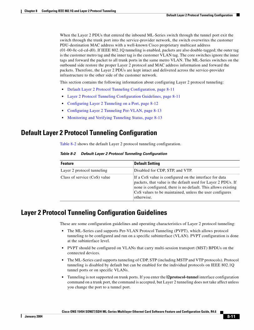
Chapter 8 Configuring IEEE 802.1Q and Layer 2 Protocol TunnelingDefault Layer 2 Protocol Tunneling Configuration
When the Layer 2 PDUs that entered the inbound ML-Series switch through the tunnel port exit the switch through the trunk port into the service-provider network, the switch overwrites the customer PDU-destination MAC address with a well-known Cisco proprietary multicast address (01-00-0c-cd-cd-d0). If IEEE 802.1Q tunneling is enabled, packets are also double-tagged; the outer tag is the customer metro tag and the inner tag is the customer VLAN tag. The core switches ignore the inner tags and forward the packet to all trunk ports in the same metro VLAN. The ML-Series switches on the outbound side restore the proper Layer 2 protocol and MAC address information and forward the packets. Therefore, the Layer 2 PDUs are kept intact and delivered across the service-provider infrastructure to the other side of the customer network.
This section contains the following information about configuring Layer 2 protocol tunneling:
• Default Layer 2 Protocol Tunneling Configuration, page 8-11
• Layer 2 Protocol Tunneling Configuration Guidelines, page 8-11
• Configuring Layer 2 Tunneling on a Port, page 8-12
• Configuring Layer 2 Tunneling Per-VLAN, page 8-13
• Monitoring and Verifying Tunneling Status, page 8-13
Default Layer 2 Protocol Tunneling ConfigurationTable 8-2 shows the default Layer 2 protocol tunneling configuration.
Layer 2 Protocol Tunneling Configuration GuidelinesThese are some configuration guidelines and operating characteristics of Layer 2 protocol tunneling:
• The ML-Series card supports Per-VLAN Protocol Tunneling (PVPT), which allows protocol tunneling to be configured and run on a specific subinterface (VLAN). PVPT configuration is done at the subinterface level.
• PVPT should be configured on VLANs that carry multi-session transport (MST) BPDUs on the connected devices.
• The ML-Series card supports tunneling of CDP, STP (including MSTP and VTP protocols). Protocol tunneling is disabled by default but can be enabled for the individual protocols on IEEE 802.1Q tunnel ports or on specific VLANs.
• Tunneling is not supported on trunk ports. If you enter the l2protocol-tunnel interface configuration command on a trunk port, the command is accepted, but Layer 2 tunneling does not take affect unless you change the port to a tunnel port.
Table 8-2 Default Layer 2 Protocol Tunneling Configuration
Feature Default Setting
Layer 2 protocol tunneling Disabled for CDP, STP, and VTP.
Class of service (CoS) value If a CoS value is configured on the interface for data packets, that value is the default used for Layer 2 PDUs. If none is configured, there is no default. This allows existing CoS values to be maintained, unless the user configures otherwise.
8-11Cisco ONS 15454 SONET/SDH ML-Series Multilayer Ethernet Card Software Feature and Configuration Guide, R4.6
January 2004

Chapter 8 Configuring IEEE 802.1Q and Layer 2 Protocol TunnelingConfiguring Layer 2 Tunneling on a Port
• EtherChannel port groups are compatible with tunnel ports as long as the IEEE 802.1Q configuration is consistent within an EtherChannel port group.
• If an encapsulated PDU (with the proprietary destination MAC address) is received from a tunnel port or access port with Layer 2 tunneling enabled, the tunnel port is shut down to prevent loops.
• Only decapsulated PDUs are forwarded to the customer network. The spanning tree instance running on the service-provider network does not forward BPDUs to tunnel ports. No CDP packets are forwarded from tunnel ports.
• Because tunneled PDUs (especially STP BPDUs) must be delivered to all remote sites for the customer virtual network to operate properly, you can give PDUs higher priority within the service-provider network than data packets received from the same tunnel port. By default, the PDUs use the same CoS value as data packets.
• Protocol tunneling has to be configured symmetrically at both the ingress and egress point. For example, if you configure the entry point to tunnel STP, CDP, VTP, then you must configure the egress point in the same way.
Configuring Layer 2 Tunneling on a PortBeginning in privileged EXEC mode, follow these steps to configure a port as a Layer 2 tunnel port:
Command Purpose
Step 1 Router# configuration terminal Enters global configuration mode.
Step 2 Router(config)# bridge bridge-group-number protocol type
Creates a bridge group number and specifies a protocol.
Step 3 Router(config)# l2protocol-tunnel cos cos-value
Associates a CoS value with the Layer 2 tunneling port. Valid numbers for a cos-value range from 0 to 7.
Step 4 Router(config)# interface type number Enters interface configuration mode for the interface to be configured as a tunnel port.
Step 5 Router(config-if)# bridge-group number Specifies the default VLAN, which is used if the interface stops trunking. This is VLAN ID specific to the particular customer.
Step 6 Router(config-if)# mode dot1q tunnel Sets the interface as an IEEE 802.1Q tunnel VLAN.
Step 7 Router(config-if)# l2protocol-tunnel {all | cdp | stp | vtp]}
Sets the interface as a Layer 2 protocol tunnel port and enables all three protocols or specifically enables CDP, STP, or VTP. These protocols are off by default.
Step 8 Router(config-if)# end Returns to privileged EXEC mode.
Step 9 Router# show dot1q-tunnel Displays the tunnel ports on the switch.
Step 10 Router# copy running-config startup-config
(Optional) Saves your entries in the configuration file.
8-12Cisco ONS 15454 SONET/SDH ML-Series Multilayer Ethernet Card Software Feature and Configuration Guide, R4.6
January 2004
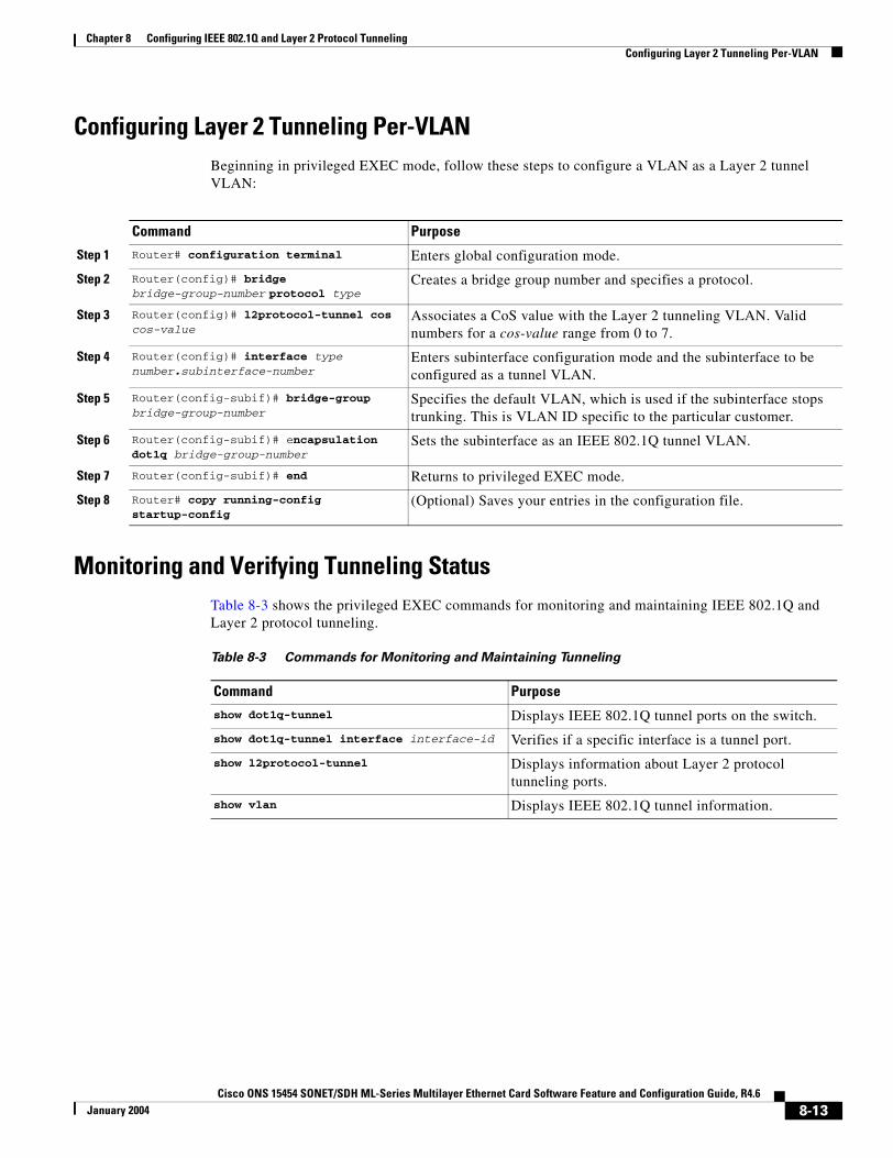
Chapter 8 Configuring IEEE 802.1Q and Layer 2 Protocol TunnelingConfiguring Layer 2 Tunneling Per-VLAN
Configuring Layer 2 Tunneling Per-VLANBeginning in privileged EXEC mode, follow these steps to configure a VLAN as a Layer 2 tunnel VLAN:
Monitoring and Verifying Tunneling StatusTable 8-3 shows the privileged EXEC commands for monitoring and maintaining IEEE 802.1Q and Layer 2 protocol tunneling.
Command Purpose
Step 1 Router# configuration terminal Enters global configuration mode.
Step 2 Router(config)# bridge bridge-group-number protocol type
Creates a bridge group number and specifies a protocol.
Step 3 Router(config)# l2protocol-tunnel cos cos-value
Associates a CoS value with the Layer 2 tunneling VLAN. Valid numbers for a cos-value range from 0 to 7.
Step 4 Router(config)# interface type number.subinterface-number
Enters subinterface configuration mode and the subinterface to be configured as a tunnel VLAN.
Step 5 Router(config-subif)# bridge-group bridge-group-number
Specifies the default VLAN, which is used if the subinterface stops trunking. This is VLAN ID specific to the particular customer.
Step 6 Router(config-subif)# encapsulation dot1q bridge-group-number
Sets the subinterface as an IEEE 802.1Q tunnel VLAN.
Step 7 Router(config-subif)# end Returns to privileged EXEC mode.
Step 8 Router# copy running-config startup-config
(Optional) Saves your entries in the configuration file.
Table 8-3 Commands for Monitoring and Maintaining Tunneling
Command Purpose
show dot1q-tunnel Displays IEEE 802.1Q tunnel ports on the switch.
show dot1q-tunnel interface interface-id Verifies if a specific interface is a tunnel port.
show l2protocol-tunnel Displays information about Layer 2 protocol tunneling ports.
show vlan Displays IEEE 802.1Q tunnel information.
8-13Cisco ONS 15454 SONET/SDH ML-Series Multilayer Ethernet Card Software Feature and Configuration Guide, R4.6
January 2004

Chapter 8 Configuring IEEE 802.1Q and Layer 2 Protocol TunnelingMonitoring and Verifying Tunneling Status
8-14Cisco ONS 15454 SONET/SDH ML-Series Multilayer Ethernet Card Software Feature and Configuration Guide, R4.6
January 2004
Cisco ONS 15454 SONET/SDH ML-Series Multilayer Ethernet Card SoftwarJanuary 2004
C H A P T E R 9
Configuring Link AggregationThis chapter describes how to configure link aggregation for the ML-Series cards, both EtherChannel and Packet-over-SONET/SDH (POS) channel. For additional information about the Cisco IOS commands used in this chapter, refer to the Cisco IOS Command Reference publication.
This chapter contains the following major sections:
• Understanding Link Aggregation, page 9-1
• Understanding Encapsulation over EtherChannel or POS Channel, page 9-7
• Monitoring and Verifying EtherChannel and POS, page 9-9
Understanding Link AggregationThe ML-Series card offers both EtherChannel and POS channel. Traditionally EtherChannel is a trunking technology that groups together multiple full-duplex IEEE 802.3 Ethernet interfaces to provide fault-tolerant high-speed links between switches, routers, and servers. EtherChannel is a logical aggregation of multiple Ethernet interfaces. EtherChannel forms a single higher bandwidth routing or bridging endpoint and was designed primarily for host-to-switch connectivity. The ML-Series card extends this link aggregation technology to bridged POS interfaces.
Link aggregation provides the following benefits:
• Logical aggregation of bandwidth
• Load balancing
• Fault tolerance
The EtherChannel interface, consisting of multiple Fast Ethernet, Gigabit Ethernet, or POS interfaces, is treated as a single interface, which is called a port channel. You must perform all EtherChannel configurations on the EtherChannel interface (port channel) rather than on the individual member Ethernet interfaces. You can create the EtherChannel interface by entering the interface port-channel interface configuration command. Each ML100T-12 supports up to 7 Fast EtherChannel (FEC) interfaces or port channels (6 Fast Ethernet and 1 POS). Each ML1000-2 supports up to 2 Gigabit EtherChannel (GEC) interfaces or port channels (1 Gigabit Ethernet and 1 POS.)
EtherChannel connections are fully compatible with IEEE 802.1Q trunking and routing technologies. IEEE 802.1Q trunking can carry multiple VLANs across an EtherChannel.
Cisco’s FEC technology builds upon standards-based IEEE 802.3 full-duplex Fast Ethernet to provide a reliable high-speed solution for the campus network backbone. FEC provides bandwidth scalability within the campus by providing up to 400-Mbps full-duplex Fast Ethernet on the ML100-12.
9-1e Feature and Configuration Guide, R4.6
Chapter 9 Configuring Link AggregationConfiguring EtherChannel
Cisco’s GEC technology provides bandwidth scalability by providing 2-Gbps full-duplex aggregate capacity on the ML1000-2.
Cisco’s POS channel technology provide bandwidth scalability by providing up to 48 STSs or VC4-16c of aggregate capacity on either the ML100-12 or the ML1000-2.
Caution The EtherChannel interface is the Layer 2/Layer 3 interface. Do not enable Layer 3 addresses on the physical interfaces. Do not assign bridge groups on the physical interfaces because doing so creates loops.
Caution Before a physical interface is removed from an EtherChannel (port channel) interface, the physical interface must be disabled. To disable a physical interface, use the shutdown command in interface configuration mode.
Note Link aggregation across multiple ML-Series cards is not supported.
Note Policing is not supported on port channel interfaces.
Note The ML-Series does not support the routing of Subnetwork Access Protocol (SNAP) or Inter-Switch Link (ISL) encapsulated frames.
Configuring EtherChannelYou can configure an FEC or a GEC by creating an EtherChannel interface (port channel) and assigning a network IP address. All interfaces that are members of a FEC or a GEC should have the same link parameters, such as duplex and speed.
To create an EtherChannel interface, perform the following procedure, beginning in global configuration mode:
Command Purpose
Step 1 Router(config)# interface port-channel channel-number
Creates the EtherChannel interface. You can configure up to 6 FECs on the ML100T-12 and 1 GEC on the ML1000-2.
Step 2 Router(config-if)# ip address ip-address subnet-mask
Assigns an IP address and subnet mask to the EtherChannel interface (required only for Layer 3 EtherChannel).
Step 3 Router(config-if)# end Exits to privileged EXEC mode.
Step 4 Router# copy running-config startup-config (Optional) Saves configuration changes to NVRAM.
9-2Cisco ONS 15454 SONET/SDH ML-Series Multilayer Ethernet Card Software Feature and Configuration Guide, R4.6
January 2004
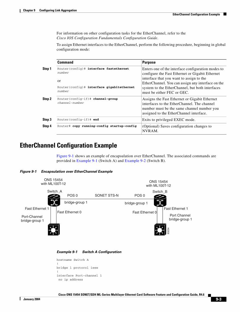
Chapter 9 Configuring Link AggregationEtherChannel Configuration Example
For information on other configuration tasks for the EtherChannel, refer to theCisco IOS Configuration Fundamentals Configuration Guide.
To assign Ethernet interfaces to the EtherChannel, perform the following procedure, beginning in global configuration mode:
EtherChannel Configuration ExampleFigure 9-1 shows an example of encapsulation over EtherChannel. The associated commands are provided in Example 9-1 (Switch A) and Example 9-2 (Switch B).
Figure 9-1 Encapsulation over EtherChannel Example
Example 9-1 Switch A Configuration
hostname Switch A!bridge 1 protocol ieee!interface Port-channel 1 no ip address
Command Purpose
Step 1 Router(config)# interface fastethernet number
or
Router(config)# interface gigabitethernet number
Enters one of the interface configuration modes to configure the Fast Ethernet or Gigabit Ethernet interface that you want to assign to the EtherChannel. You can assign any interface on the system to the EtherChannel, but both interfaces must be either FEC or GEC.
Step 2 Router(config-if)# channel-group channel-number
Assigns the Fast Ethernet or Gigabit Ethernet interfaces to the EtherChannel. The channel number must be the same channel number you assigned to the EtherChannel interface.
Step 3 Router(config-if)# end Exits to privileged EXEC mode.
Step 4 Router# copy running-config startup-config (Optional) Saves configuration changes to NVRAM.
ONS 15454with ML100T-12
Fast Ethernet 0
POS 0POS 0
Fast Ethernet 0
SONET STS-N
ONS 15454with ML100T-12
Fast Ethernet 1 Fast Ethernet 1
bridge-group 1 bridge-group 1
8323
4
Port-Channel bridge-group 1
Port Channel bridge-group 1
Switch_A Switch_B
9-3Cisco ONS 15454 SONET/SDH ML-Series Multilayer Ethernet Card Software Feature and Configuration Guide, R4.6
January 2004

Chapter 9 Configuring Link AggregationConfiguring POS Channel
bridge-group 1 hold-queue 150 in!interface FastEthernet 0 no ip address channel-group 1!interface FastEthernet 1 no ip address channel-group 1!interface POS 0no ip routingno ip address crc 32bridge-group 1 pos flag c2 1
Example 9-2 Switch B Configuration
hostname Switch B!bridge 1 protocol ieee!interface Port-channel 1no ip routingno ip address bridge-group 1 hold-queue 150 in!interface FastEthernet 0 no ip address channel-group 1!interface FastEthernet 1 no ip address channel-group 1!interface POS 0 no ip address crc 32bridge-group 1 pos flag c2 1!
Configuring POS ChannelYou can configure a POS channel by creating a POS channel interface (port channel) and optionally assigning an IP address. All POS interfaces that are members of a POS channel should have the same port properties and be on the same ML-Series card.
Note POS channel is only supported with G-Series card compatible (LEX) encapsulation.
9-4Cisco ONS 15454 SONET/SDH ML-Series Multilayer Ethernet Card Software Feature and Configuration Guide, R4.6
January 2004
Chapter 9 Configuring Link AggregationPOS Channel Configuration Example
To create a POS channel interface, perform the following procedure, beginning in global configuration mode:
Caution The POS channel interface is the routed interface. Do not enable Layer 3 addresses on any physical interfaces. Do not assign bridge groups on any physical interfaces because doing so creates loops.
To assign POS interfaces to the POS channel, perform the following procedure, beginning in global configuration mode:
POS Channel Configuration ExampleFigure 9-2 shows an example of POS channel configuration. The associated code is provided in Example 9-3 (Switch A) and Example 9-4 (Switch B).
Command Purpose
Step 1 Router(config)# interface port-channel channel-number
Creates the POS channel interface. You can configure one POS channel on the ML-Series card.
Step 2 Router(config-if)# ip address ip-address subnet-mask
Assigns an IP address and subnet mask to the POS channel interface (required only for the Layer 3 POS channel).
Step 3 Router(config-if)# end Exits to privileged EXEC mode.
Step 4 Router# copy running-config startup-config (Optional) Saves configuration changes to NVRAM.
Command Purpose
Step 1 Router(config)# interface pos number Enters the interface configuration mode to configure the POS interface that you want to assign to the POS channel.
Step 2 Router(config-if)# channel-group channel-number
Assigns the POS interface to the POS channel. The channel number must be the same channel number that you assigned to the POS channel interface.
Step 3 Router(config-if)# end Exits to privileged EXEC mode.
Step 4 Router# copy running-config startup-config (Optional) Saves the configuration changes to NVRAM.
9-5Cisco ONS 15454 SONET/SDH ML-Series Multilayer Ethernet Card Software Feature and Configuration Guide, R4.6
January 2004
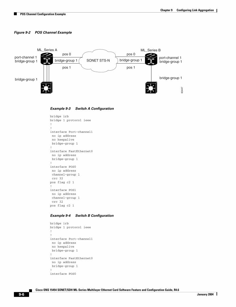
Chapter 9 Configuring Link AggregationPOS Channel Configuration Example
Figure 9-2 POS Channel Example
Example 9-3 Switch A Configuration
bridge irbbridge 1 protocol ieee!!interface Port-channel1 no ip address no keepalive bridge-group 1!interface FastEthernet0 no ip address bridge-group 1!interface POS0 no ip address channel-group 1 crc 32pos flag c2 1!interface POS1 no ip address channel-group 1 crc 32pos flag c2 1
Example 9-4 Switch B Configuration
bridge irbbridge 1 protocol ieee!!interface Port-channel1 no ip address no keepalive bridge-group 1!interface FastEthernet0 no ip address bridge-group 1!interface POS0
pos 0pos 0
bridge-group 1 bridge-group 1port-channel 1 bridge-group 1
bridge-group 1 bridge-group 1
port-channel 1 bridge-group 1
pos 1pos 1
8344
7
SONET STS-N
ML_Series A ML_Series B
9-6Cisco ONS 15454 SONET/SDH ML-Series Multilayer Ethernet Card Software Feature and Configuration Guide, R4.6
January 2004
Chapter 9 Configuring Link AggregationUnderstanding Encapsulation over EtherChannel or POS Channel
no ip address channel-group 1 crc 32pos flag c2 1!interface POS1 no ip address channel-group 1 crc 32pos flag c2 1
Understanding Encapsulation over EtherChannel or POS Channel
When configuring encapsulation over FEC, GEC, or POS, be sure to configure IEEE 802.1Q on the port-channel interface, not its member ports. However, certain attributes of port channel, such as duplex mode, need to be configured at the member port levels. Also make sure that you do not apply protocol-level configuration (such as an IP address or a bridge group assignment) to the member interfaces. All protocol-level configuration should be on the port channel or on its subinterface. You must configure IEEE 802.1Q encapsulation on the partner system of the EtherChannel as well.
Configuring Encapsulation over EtherChannel or POS ChannelTo configure encapsulation over the EtherChannel or POS channel, perform the following procedure, beginning in global configuration mode:
Encapsulation over EtherChannel ExampleFigure 9-3 shows an example of encapsulation over EtherChannel. The associated code is provided in Example 9-5 (Switch A) and Example 9-6 (Switch B).
Command Purpose
Step 1 Router(config)# interface port-channel channel-number.subinterface-number
Configures the subinterface on the created port channel.
Step 2 Router(config-subif)# encapsulation dot1q vlan-id
Assigns the IEEE 802.1Q encapsulation to the subinterface.
Step 3 Router(config-subif)# bridge-group bridge-group-number
Assigns the subinterface to a bridge group.
Step 4 Router(config-subif)# end Exits to privileged EXEC mode.
Note Optionally, you can remain in interface configuration mode and enable other supported interface commands to meet your requirements.
Step 5 Router# copy running-config startup-config (Optional) Saves the configuration changes to NVRAM.
9-7Cisco ONS 15454 SONET/SDH ML-Series Multilayer Ethernet Card Software Feature and Configuration Guide, R4.6
January 2004
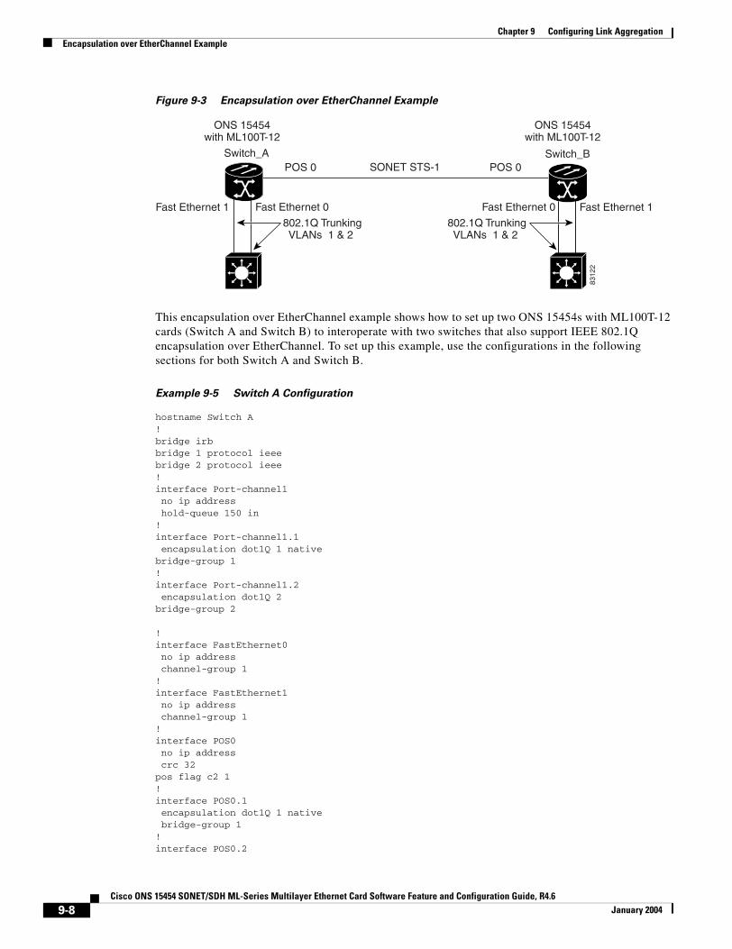
Chapter 9 Configuring Link AggregationEncapsulation over EtherChannel Example
Figure 9-3 Encapsulation over EtherChannel Example
This encapsulation over EtherChannel example shows how to set up two ONS 15454s with ML100T-12 cards (Switch A and Switch B) to interoperate with two switches that also support IEEE 802.1Q encapsulation over EtherChannel. To set up this example, use the configurations in the following sections for both Switch A and Switch B.
Example 9-5 Switch A Configuration
hostname Switch A!bridge irbbridge 1 protocol ieeebridge 2 protocol ieee!interface Port-channel1 no ip address hold-queue 150 in!interface Port-channel1.1 encapsulation dot1Q 1 nativebridge-group 1!interface Port-channel1.2 encapsulation dot1Q 2bridge-group 2
!interface FastEthernet0 no ip address channel-group 1!interface FastEthernet1 no ip address channel-group 1!interface POS0 no ip address crc 32pos flag c2 1!interface POS0.1 encapsulation dot1Q 1 native bridge-group 1!interface POS0.2
ONS 15454with ML100T-12
Fast Ethernet 0
POS 0POS 0
Fast Ethernet 0
Switch_ASONET STS-1
ONS 15454with ML100T-12
Switch_B
Fast Ethernet 1 Fast Ethernet 1
802.1Q TrunkingVLANs 1 & 2
802.1Q TrunkingVLANs 1 & 2
8312
2
9-8Cisco ONS 15454 SONET/SDH ML-Series Multilayer Ethernet Card Software Feature and Configuration Guide, R4.6
January 2004
Chapter 9 Configuring Link AggregationMonitoring and Verifying EtherChannel and POS
encapsulation dot1Q 2 bridge-group 2
Example 9-6 Switch B Configuration
hostname Switch B!bridge irbbridge 1 protocol ieeebridge 2 protocol ieee!interface Port-channel1 no ip address hold-queue 150 in!interface Port-channel1.1 encapsulation dot1Q 1 nativebridge-group 1!interface Port-channel1.2 encapsulation dot1Q 2bridge-group 2!interface FastEthernet0 no ip address channel-group 1!interface FastEthernet1 no ip address channel-group 1!interface POS0 no ip address crc 32pos flag c2 1!interface POS0.1 encapsulation dot1Q 1 native bridge-group 1!interface POS0.2 encapsulation dot1Q 2 bridge-group 2!
Monitoring and Verifying EtherChannel and POSAfter FEC, GEC, or POS is configured, you can monitor its status using the show interfaces port-channel command.
Example 9-7 show interfaces port-channel Command
Router# show int port-channel 1Port-channel1 is up, line protocol is up Hardware is FEChannel, address is 0005.9a39.6634 (bia 0000.0000.0000) MTU 1500 bytes, BW 200000 Kbit, DLY 100 usec, reliability 255/255, txload 1/255, rxload 1/255 Encapsulation ARPA, loopback not set
9-9Cisco ONS 15454 SONET/SDH ML-Series Multilayer Ethernet Card Software Feature and Configuration Guide, R4.6
January 2004

Chapter 9 Configuring Link AggregationMonitoring and Verifying EtherChannel and POS
Keepalive set (10 sec) Unknown duplex, Unknown Speed ARP type: ARPA, ARP Timeout 04:00:00 No. of active members in this channel: 2 Member 0 : FastEthernet0 , Full-duplex, Auto Speed Member 1 : FastEthernet1 , Full-duplex, Auto Speed Last input 00:00:01, output 00:00:23, output hang never Last clearing of "show interface" counters never Input queue: 0/150/0/0 (size/max/drops/flushes); Total output drops: 0 Queueing strategy: fifo Output queue :0/80 (size/max) 5 minute input rate 0 bits/sec, 0 packets/sec 5 minute output rate 0 bits/sec, 0 packets/sec 820 packets input, 59968 bytes Received 0 broadcasts, 0 runts, 0 giants, 0 throttles 0 input errors, 0 CRC, 0 frame, 0 overrun, 0 ignored 0 watchdog, 0 multicast 0 input packets with dribble condition detected 32 packets output, 11264 bytes, 0 underruns 0 output errors, 0 collisions, 0 interface resets 0 babbles, 0 late collision, 0 deferred 0 lost carrier, 0 no carrier 0 output buffer failures, 0 output buffers swapped out.
9-10Cisco ONS 15454 SONET/SDH ML-Series Multilayer Ethernet Card Software Feature and Configuration Guide, R4.6
January 2004
Cisco ONS 15454 SONET/SDH ML-Series Multilayer Ethernet Card SoftwarJanuary 2004
C H A P T E R 10
Configuring Networking ProtocolsThis chapter describes how to configure the ML-Series card for supported IP routing protocols. It is intended to provide enough information for a network administrator to get the protocols up and running. However, this section does not provide in-depth configuration detail for each protocol. For detailed information, refer to the Cisco IOS IP and IP Routing Configuration Guide and the Cisco IOS IP and IP Routing Command Reference publications.
This chapter contains the following major sections:
• Basic IP Routing Protocol Configuration, page 10-1
• Configuring IP Routing, page 10-4
• Monitoring Static Routes, page 10-32
• Monitoring and Maintaining the IP Network, page 10-33
• Understanding IP Multicast Routing, page 10-33
• Configuring IP Multicast Routing, page 10-34
• Monitoring and Verifying IP Multicast Operation, page 10-35
Basic IP Routing Protocol ConfigurationIP routing is enabled by default on the ML-Series card.
For IP routing, you need the following to configure your interface:
• IP address
• IP subnet mask
You also need to do the following:
• Select a routing protocol.
• Assign IP network numbers to be advertised.
The ML Series supports the routing protocols listed and described in the following sections.
To configure IP routing protocols to run on a Fast Ethernet, Gigabit Ethernet, or Packet-over-SONET/SDH (POS) interface, perform one of the following procedures, depending on the protocol you are configuring.
10-1e Feature and Configuration Guide, R4.6
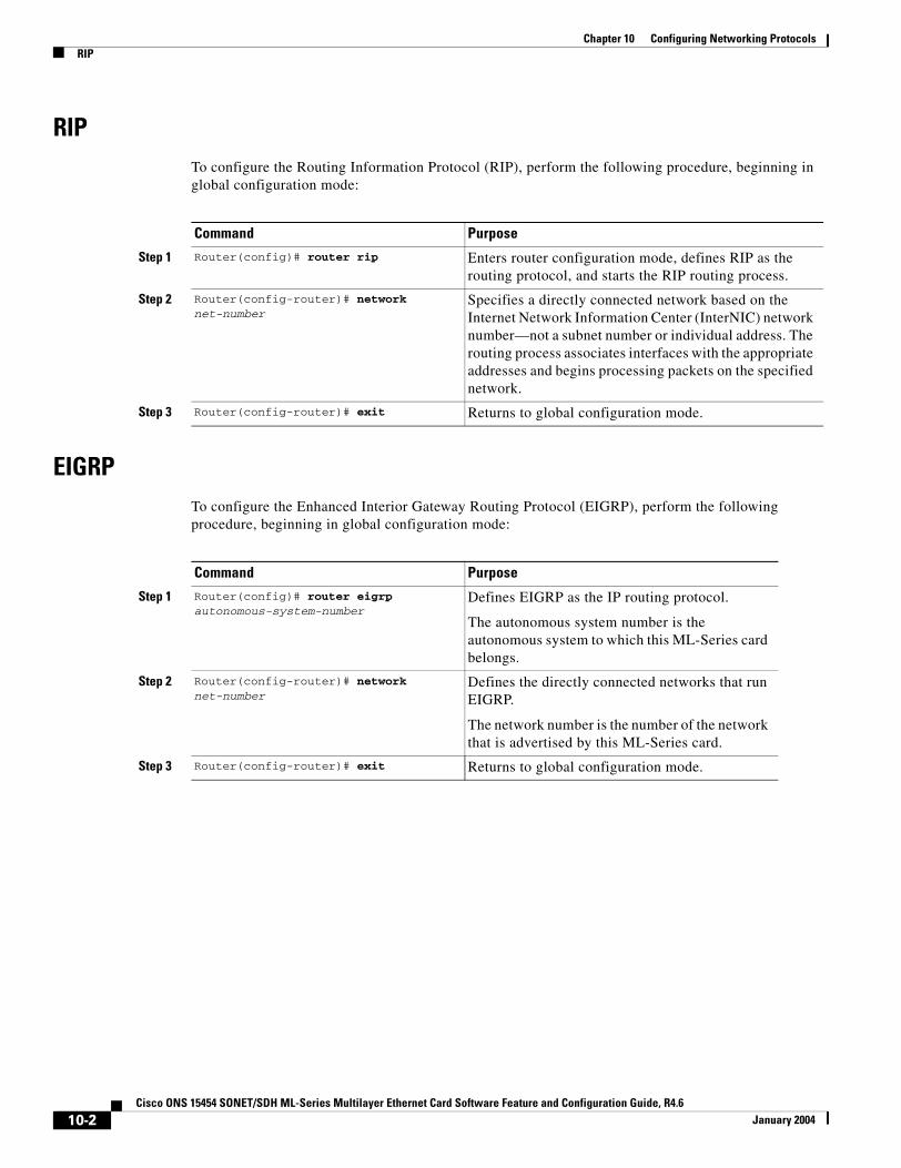
Chapter 10 Configuring Networking ProtocolsRIP
RIPTo configure the Routing Information Protocol (RIP), perform the following procedure, beginning in global configuration mode:
EIGRPTo configure the Enhanced Interior Gateway Routing Protocol (EIGRP), perform the following procedure, beginning in global configuration mode:
Command Purpose
Step 1 Router(config)# router rip Enters router configuration mode, defines RIP as the routing protocol, and starts the RIP routing process.
Step 2 Router(config-router)# network net-number
Specifies a directly connected network based on the Internet Network Information Center (InterNIC) network number—not a subnet number or individual address. The routing process associates interfaces with the appropriate addresses and begins processing packets on the specified network.
Step 3 Router(config-router)# exit Returns to global configuration mode.
Command Purpose
Step 1 Router(config)# router eigrp autonomous-system-number
Defines EIGRP as the IP routing protocol.
The autonomous system number is the autonomous system to which this ML-Series card belongs.
Step 2 Router(config-router)# network net-number
Defines the directly connected networks that run EIGRP.
The network number is the number of the network that is advertised by this ML-Series card.
Step 3 Router(config-router)# exit Returns to global configuration mode.
10-2Cisco ONS 15454 SONET/SDH ML-Series Multilayer Ethernet Card Software Feature and Configuration Guide, R4.6
January 2004
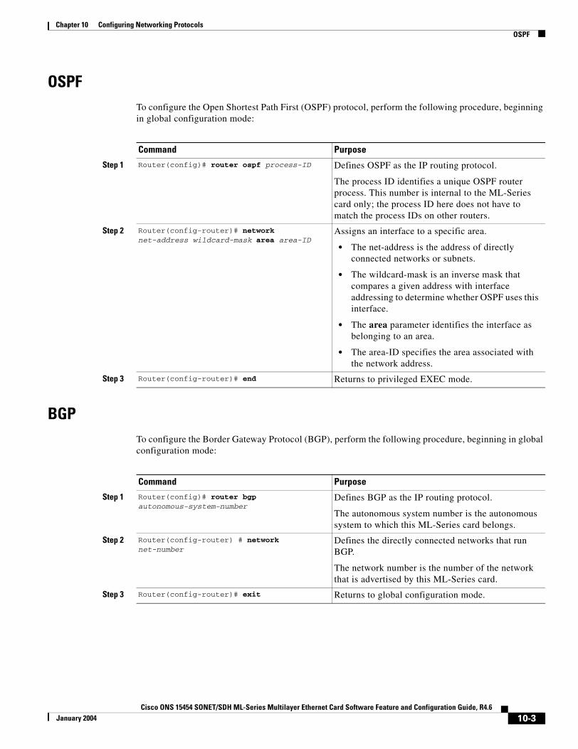
Chapter 10 Configuring Networking ProtocolsOSPF
OSPFTo configure the Open Shortest Path First (OSPF) protocol, perform the following procedure, beginning in global configuration mode:
BGPTo configure the Border Gateway Protocol (BGP), perform the following procedure, beginning in global configuration mode:
Command Purpose
Step 1 Router(config)# router ospf process-ID Defines OSPF as the IP routing protocol.
The process ID identifies a unique OSPF router process. This number is internal to the ML-Series card only; the process ID here does not have to match the process IDs on other routers.
Step 2 Router(config-router)# network net-address wildcard-mask area area-ID
Assigns an interface to a specific area.
• The net-address is the address of directly connected networks or subnets.
• The wildcard-mask is an inverse mask that compares a given address with interface addressing to determine whether OSPF uses this interface.
• The area parameter identifies the interface as belonging to an area.
• The area-ID specifies the area associated with the network address.
Step 3 Router(config-router)# end Returns to privileged EXEC mode.
Command Purpose
Step 1 Router(config)# router bgp autonomous-system-number
Defines BGP as the IP routing protocol.
The autonomous system number is the autonomous system to which this ML-Series card belongs.
Step 2 Router(config-router) # network net-number
Defines the directly connected networks that run BGP.
The network number is the number of the network that is advertised by this ML-Series card.
Step 3 Router(config-router)# exit Returns to global configuration mode.
10-3Cisco ONS 15454 SONET/SDH ML-Series Multilayer Ethernet Card Software Feature and Configuration Guide, R4.6
January 2004
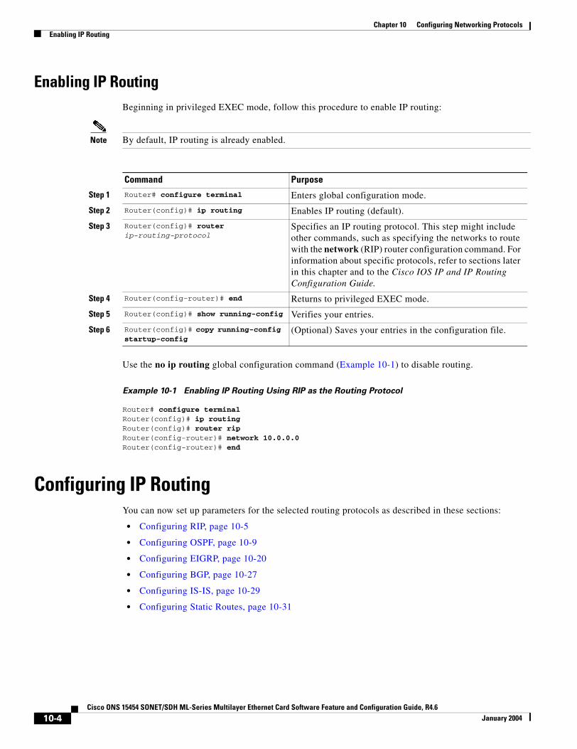
Chapter 10 Configuring Networking ProtocolsEnabling IP Routing
Enabling IP Routing Beginning in privileged EXEC mode, follow this procedure to enable IP routing:
Note By default, IP routing is already enabled.
Use the no ip routing global configuration command (Example 10-1) to disable routing.
Example 10-1 Enabling IP Routing Using RIP as the Routing Protocol
Router# configure terminal Router(config)# ip routing Router(config)# router rip Router(config-router)# network 10.0.0.0 Router(config-router)# end
Configuring IP RoutingYou can now set up parameters for the selected routing protocols as described in these sections:
• Configuring RIP, page 10-5
• Configuring OSPF, page 10-9
• Configuring EIGRP, page 10-20
• Configuring BGP, page 10-27
• Configuring IS-IS, page 10-29
• Configuring Static Routes, page 10-31
Command Purpose
Step 1 Router# configure terminal Enters global configuration mode.
Step 2 Router(config)# ip routing Enables IP routing (default).
Step 3 Router(config)# router ip-routing-protocol
Specifies an IP routing protocol. This step might include other commands, such as specifying the networks to route with the network (RIP) router configuration command. For information about specific protocols, refer to sections later in this chapter and to the Cisco IOS IP and IP Routing Configuration Guide.
Step 4 Router(config-router)# end Returns to privileged EXEC mode.
Step 5 Router(config)# show running-config Verifies your entries.
Step 6 Router(config)# copy running-config startup-config
(Optional) Saves your entries in the configuration file.
10-4Cisco ONS 15454 SONET/SDH ML-Series Multilayer Ethernet Card Software Feature and Configuration Guide, R4.6
January 2004
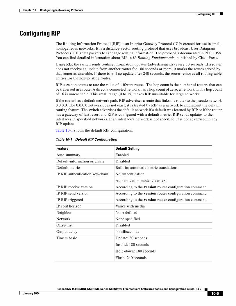
Chapter 10 Configuring Networking ProtocolsConfiguring RIP
Configuring RIPThe Routing Information Protocol (RIP) is an Interior Gateway Protocol (IGP) created for use in small, homogeneous networks. It is a distance-vector routing protocol that uses broadcast User Datagram Protocol (UDP) data packets to exchange routing information. The protocol is documented in RFC 1058. You can find detailed information about RIP in IP Routing Fundamentals, published by Cisco Press.
Using RIP, the switch sends routing information updates (advertisements) every 30 seconds. If a router does not receive an update from another router for 180 seconds or more, it marks the routes served by that router as unusable. If there is still no update after 240 seconds, the router removes all routing table entries for the nonupdating router.
RIP uses hop counts to rate the value of different routes. The hop count is the number of routers that can be traversed in a route. A directly connected network has a hop count of zero; a network with a hop count of 16 is unreachable. This small range (0 to 15) makes RIP unsuitable for large networks.
If the router has a default network path, RIP advertises a route that links the router to the pseudo network 0.0.0.0. The 0.0.0.0 network does not exist; it is treated by RIP as a network to implement the default routing feature. The switch advertises the default network if a default was learned by RIP or if the router has a gateway of last resort and RIP is configured with a default metric. RIP sends updates to the interfaces in specified networks. If an interface’s network is not specified, it is not advertised in any RIP update.
Table 10-1 shows the default RIP configuration.
Table 10-1 Default RIP Configuration
Feature Default Setting
Auto summary Enabled
Default-information originate Disabled
Default metric Built-in; automatic metric translations
IP RIP authentication key-chain No authentication
Authentication mode: clear text
IP RIP receive version According to the version router configuration command
IP RIP send version According to the version router configuration command
IP RIP triggered According to the version router configuration command
IP split horizon Varies with media
Neighbor None defined
Network None specified
Offset list Disabled
Output delay 0 milliseconds
Timers basic Update: 30 seconds
Invalid: 180 seconds
Hold-down: 180 seconds
Flush: 240 seconds
10-5Cisco ONS 15454 SONET/SDH ML-Series Multilayer Ethernet Card Software Feature and Configuration Guide, R4.6
January 2004
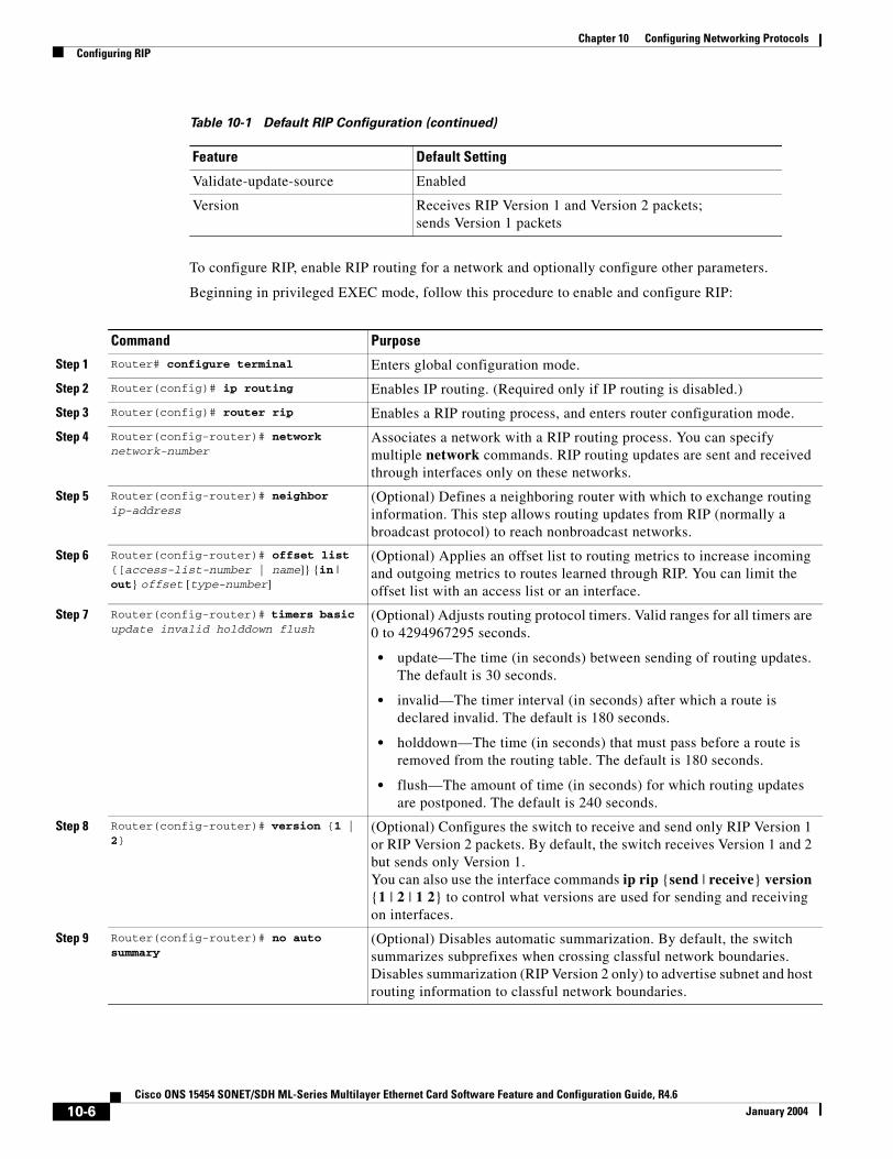
Chapter 10 Configuring Networking ProtocolsConfiguring RIP
To configure RIP, enable RIP routing for a network and optionally configure other parameters.
Beginning in privileged EXEC mode, follow this procedure to enable and configure RIP:
Validate-update-source Enabled
Version Receives RIP Version 1 and Version 2 packets; sends Version 1 packets
Table 10-1 Default RIP Configuration (continued)
Feature Default Setting
Command Purpose
Step 1 Router# configure terminal Enters global configuration mode.
Step 2 Router(config)# ip routing Enables IP routing. (Required only if IP routing is disabled.)
Step 3 Router(config)# router rip Enables a RIP routing process, and enters router configuration mode.
Step 4 Router(config-router)# network network-number
Associates a network with a RIP routing process. You can specify multiple network commands. RIP routing updates are sent and received through interfaces only on these networks.
Step 5 Router(config-router)# neighbor ip-address
(Optional) Defines a neighboring router with which to exchange routing information. This step allows routing updates from RIP (normally a broadcast protocol) to reach nonbroadcast networks.
Step 6 Router(config-router)# offset list {[access-list-number | name]} {in | out} offset [type-number]
(Optional) Applies an offset list to routing metrics to increase incoming and outgoing metrics to routes learned through RIP. You can limit the offset list with an access list or an interface.
Step 7 Router(config-router)# timers basic update invalid holddown flush
(Optional) Adjusts routing protocol timers. Valid ranges for all timers are 0 to 4294967295 seconds.
• update—The time (in seconds) between sending of routing updates. The default is 30 seconds.
• invalid—The timer interval (in seconds) after which a route is declared invalid. The default is 180 seconds.
• holddown—The time (in seconds) that must pass before a route is removed from the routing table. The default is 180 seconds.
• flush—The amount of time (in seconds) for which routing updates are postponed. The default is 240 seconds.
Step 8 Router(config-router)# version {1 | 2}
(Optional) Configures the switch to receive and send only RIP Version 1 or RIP Version 2 packets. By default, the switch receives Version 1 and 2 but sends only Version 1. You can also use the interface commands ip rip {send | receive} version {1 | 2 | 1 2} to control what versions are used for sending and receiving on interfaces.
Step 9 Router(config-router)# no auto summary
(Optional) Disables automatic summarization. By default, the switch summarizes subprefixes when crossing classful network boundaries. Disables summarization (RIP Version 2 only) to advertise subnet and host routing information to classful network boundaries.
10-6Cisco ONS 15454 SONET/SDH ML-Series Multilayer Ethernet Card Software Feature and Configuration Guide, R4.6
January 2004
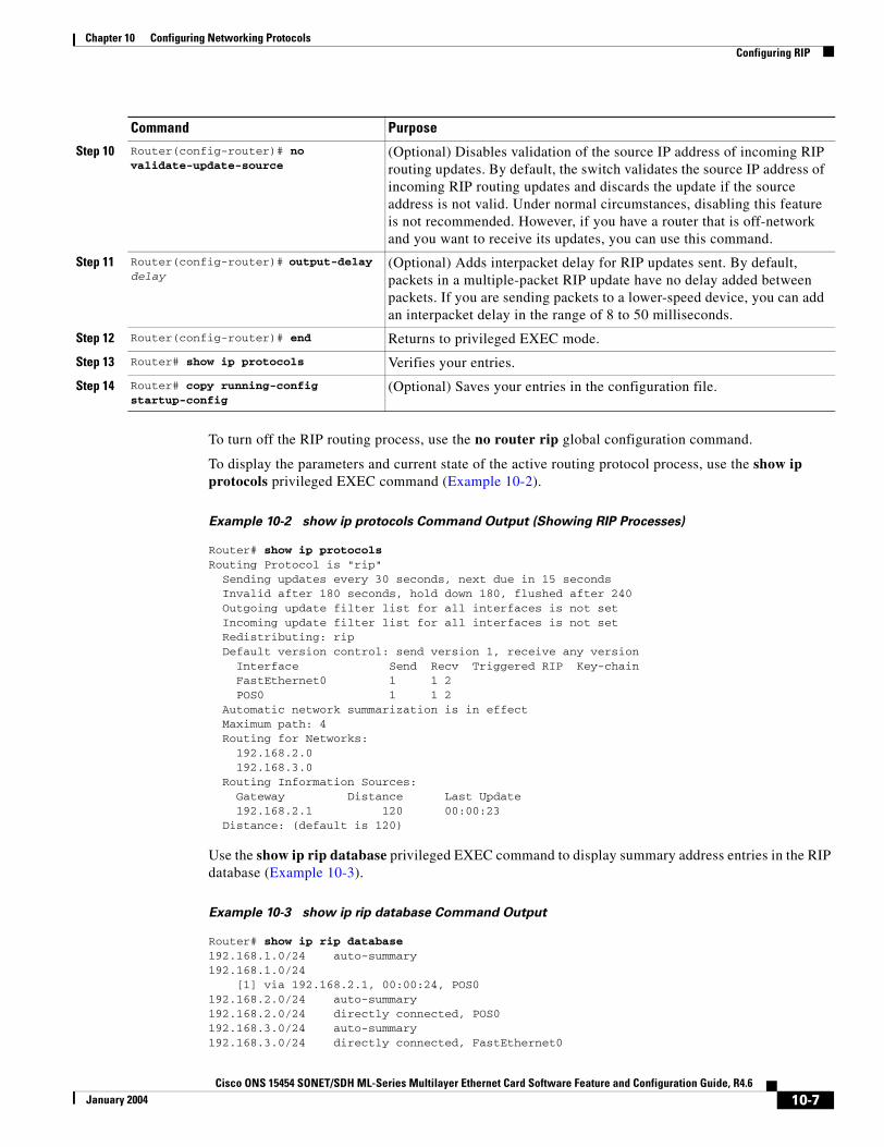
Chapter 10 Configuring Networking ProtocolsConfiguring RIP
To turn off the RIP routing process, use the no router rip global configuration command.
To display the parameters and current state of the active routing protocol process, use the show ip protocols privileged EXEC command (Example 10-2).
Example 10-2 show ip protocols Command Output (Showing RIP Processes)
Router# show ip protocolsRouting Protocol is "rip" Sending updates every 30 seconds, next due in 15 seconds Invalid after 180 seconds, hold down 180, flushed after 240 Outgoing update filter list for all interfaces is not set Incoming update filter list for all interfaces is not set Redistributing: rip Default version control: send version 1, receive any version Interface Send Recv Triggered RIP Key-chain FastEthernet0 1 1 2 POS0 1 1 2 Automatic network summarization is in effect Maximum path: 4 Routing for Networks: 192.168.2.0 192.168.3.0 Routing Information Sources: Gateway Distance Last Update 192.168.2.1 120 00:00:23 Distance: (default is 120)
Use the show ip rip database privileged EXEC command to display summary address entries in the RIP database (Example 10-3).
Example 10-3 show ip rip database Command Output
Router# show ip rip database192.168.1.0/24 auto-summary192.168.1.0/24 [1] via 192.168.2.1, 00:00:24, POS0192.168.2.0/24 auto-summary192.168.2.0/24 directly connected, POS0192.168.3.0/24 auto-summary192.168.3.0/24 directly connected, FastEthernet0
Step 10 Router(config-router)# no validate-update-source
(Optional) Disables validation of the source IP address of incoming RIP routing updates. By default, the switch validates the source IP address of incoming RIP routing updates and discards the update if the source address is not valid. Under normal circumstances, disabling this feature is not recommended. However, if you have a router that is off-network and you want to receive its updates, you can use this command.
Step 11 Router(config-router)# output-delay delay
(Optional) Adds interpacket delay for RIP updates sent. By default, packets in a multiple-packet RIP update have no delay added between packets. If you are sending packets to a lower-speed device, you can add an interpacket delay in the range of 8 to 50 milliseconds.
Step 12 Router(config-router)# end Returns to privileged EXEC mode.
Step 13 Router# show ip protocols Verifies your entries.
Step 14 Router# copy running-config startup-config
(Optional) Saves your entries in the configuration file.
Command Purpose
10-7Cisco ONS 15454 SONET/SDH ML-Series Multilayer Ethernet Card Software Feature and Configuration Guide, R4.6
January 2004
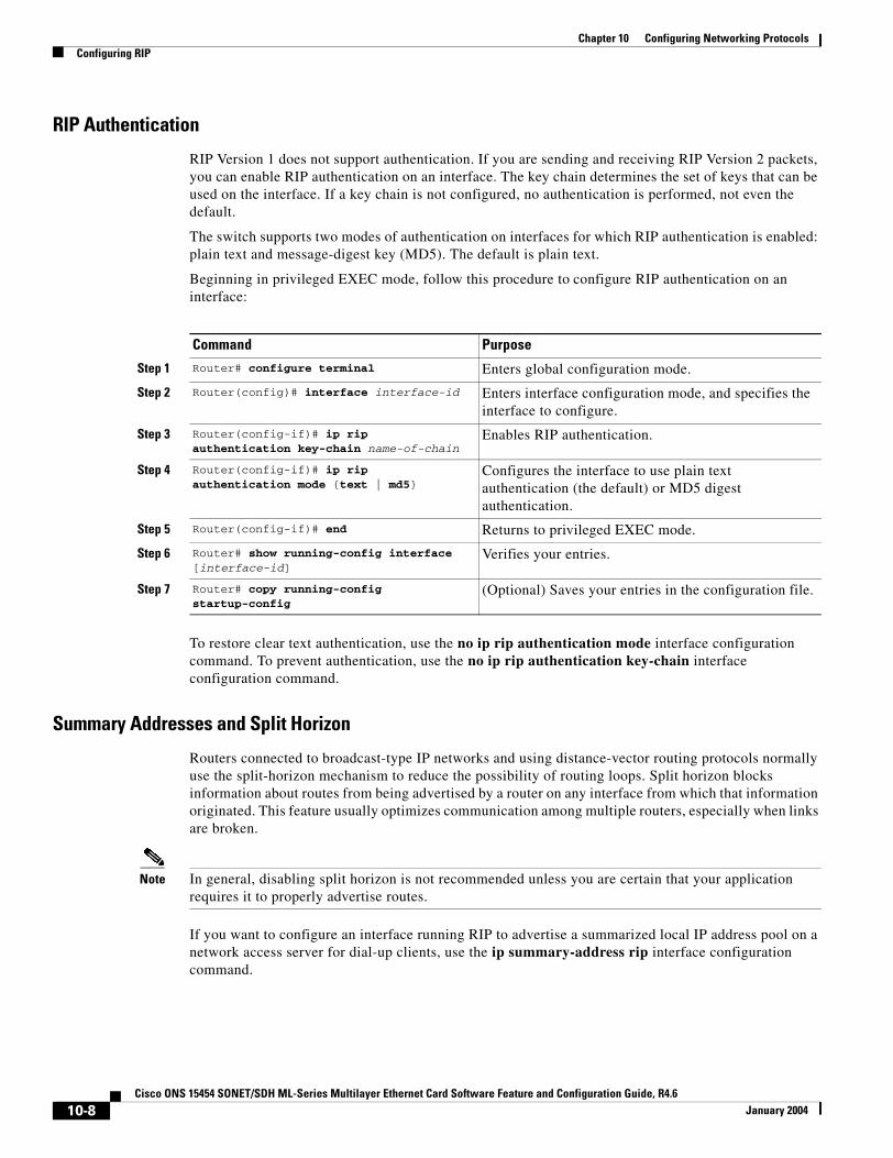
Chapter 10 Configuring Networking ProtocolsConfiguring RIP
RIP Authentication
RIP Version 1 does not support authentication. If you are sending and receiving RIP Version 2 packets, you can enable RIP authentication on an interface. The key chain determines the set of keys that can be used on the interface. If a key chain is not configured, no authentication is performed, not even the default.
The switch supports two modes of authentication on interfaces for which RIP authentication is enabled: plain text and message-digest key (MD5). The default is plain text.
Beginning in privileged EXEC mode, follow this procedure to configure RIP authentication on an interface:
To restore clear text authentication, use the no ip rip authentication mode interface configuration command. To prevent authentication, use the no ip rip authentication key-chain interface configuration command.
Summary Addresses and Split Horizon
Routers connected to broadcast-type IP networks and using distance-vector routing protocols normally use the split-horizon mechanism to reduce the possibility of routing loops. Split horizon blocks information about routes from being advertised by a router on any interface from which that information originated. This feature usually optimizes communication among multiple routers, especially when links are broken.
Note In general, disabling split horizon is not recommended unless you are certain that your application requires it to properly advertise routes.
If you want to configure an interface running RIP to advertise a summarized local IP address pool on a network access server for dial-up clients, use the ip summary-address rip interface configuration command.
Command Purpose
Step 1 Router# configure terminal Enters global configuration mode.
Step 2 Router(config)# interface interface-id Enters interface configuration mode, and specifies the interface to configure.
Step 3 Router(config-if)# ip rip authentication key-chain name-of-chain
Enables RIP authentication.
Step 4 Router(config-if)# ip rip authentication mode {text | md5}
Configures the interface to use plain text authentication (the default) or MD5 digest authentication.
Step 5 Router(config-if)# end Returns to privileged EXEC mode.
Step 6 Router# show running-config interface [interface-id]
Verifies your entries.
Step 7 Router# copy running-config startup-config
(Optional) Saves your entries in the configuration file.
10-8Cisco ONS 15454 SONET/SDH ML-Series Multilayer Ethernet Card Software Feature and Configuration Guide, R4.6
January 2004
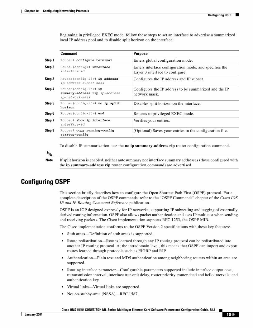
Chapter 10 Configuring Networking ProtocolsConfiguring OSPF
Beginning in privileged EXEC mode, follow these steps to set an interface to advertise a summarized local IP address pool and to disable split horizon on the interface:
To disable IP summarization, use the no ip summary-address rip router configuration command.
Note If split horizon is enabled, neither autosummary nor interface summary addresses (those configured with the ip summary-address rip router configuration command) are advertised.
Configuring OSPFThis section briefly describes how to configure the Open Shortest Path First (OSPF) protocol. For a complete description of the OSPF commands, refer to the “OSPF Commands” chapter of the Cisco IOS IP and IP Routing Command Reference publication.
OSPF is an IGP designed expressly for IP networks, supporting IP subnetting and tagging of externally derived routing information. OSPF also allows packet authentication and uses IP multicast when sending and receiving packets. The Cisco implementation supports RFC 1253, the OSPF MIB.
The Cisco implementation conforms to the OSPF Version 2 specifications with these key features:
• Stub areas—Definition of stub areas is supported.
• Route redistribution—Routes learned through any IP routing protocol can be redistributed into another IP routing protocol. At the intradomain level, this means that OSPF can import and export routes learned through protocols such as EIGRP and RIP.
• Authentication—Plain text and MD5 authentication among neighboring routers within an area are supported.
• Routing interface parameter—Configurable parameters supported include interface output cost, retransmission interval, interface transmit delay, router priority, router dead and hello intervals, and authentication key.
• Virtual links—Virtual links are supported.
• Not-so-stubby-area (NSSA)—RFC 1587.
Command Purpose
Step 1 Router# configure terminal Enters global configuration mode.
Step 2 Router(config)# interface interface-id
Enters interface configuration mode, and specifies the Layer 3 interface to configure.
Step 3 Router(config-if)# ip address ip-address subnet-mask
Configures the IP address and IP subnet.
Step 4 Router(config-if)# ip summary-address rip ip-address ip-network-mask
Configures the IP address to be summarized and the IP network mask.
Step 5 Router(config-if)# no ip split horizon
Disables split horizon on the interface.
Step 6 Router(config-if)# end Returns to privileged EXEC mode.
Step 7 Router# show ip interface interface-id
Verifies your entries.
Step 8 Router# copy running-config startup-config
(Optional) Saves your entries in the configuration file.
10-9Cisco ONS 15454 SONET/SDH ML-Series Multilayer Ethernet Card Software Feature and Configuration Guide, R4.6
January 2004
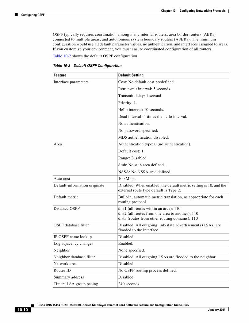
Chapter 10 Configuring Networking ProtocolsConfiguring OSPF
OSPF typically requires coordination among many internal routers, area border routers (ABRs) connected to multiple areas, and autonomous system boundary routers (ASBRs). The minimum configuration would use all default parameter values, no authentication, and interfaces assigned to areas. If you customize your environment, you must ensure coordinated configuration of all routers.
Table 10-2 shows the default OSPF configuration.
Table 10-2 Default OSPF Configuration
Feature Default Setting
Interface parameters Cost: No default cost predefined.
Retransmit interval: 5 seconds.
Transmit delay: 1 second.
Priority: 1.
Hello interval: 10 seconds.
Dead interval: 4 times the hello interval.
No authentication.
No password specified.
MD5 authentication disabled.
Area Authentication type: 0 (no authentication).
Default cost: 1.
Range: Disabled.
Stub: No stub area defined.
NSSA: No NSSA area defined.
Auto cost 100 Mbps.
Default-information originate Disabled. When enabled, the default metric setting is 10, and the external route type default is Type 2.
Default metric Built-in, automatic metric translation, as appropriate for each routing protocol.
Distance OSPF dist1 (all routes within an area): 110dist2 (all routes from one area to another): 110dist3 (routes from other routing domains): 110
OSPF database filter Disabled. All outgoing link-state advertisements (LSAs) are flooded to the interface.
IP OSPF name lookup Disabled.
Log adjacency changes Enabled.
Neighbor None specified.
Neighbor database filter Disabled. All outgoing LSAs are flooded to the neighbor.
Network area Disabled.
Router ID No OSPF routing process defined.
Summary address Disabled.
Timers LSA group pacing 240 seconds.
10-10Cisco ONS 15454 SONET/SDH ML-Series Multilayer Ethernet Card Software Feature and Configuration Guide, R4.6
January 2004

Chapter 10 Configuring Networking ProtocolsConfiguring OSPF
Figure 10-1 shows an example of an IP routing protocol using OSPF.
Figure 10-1 IP Routing Protocol Example Using OSPF
Enabling OSPF requires that you create an OSPF routing process, specify the range of IP addresses to be associated with the routing process, and assign area IDs to be associated with that range.
Timers shortest path first (spf) spf delay: 5 seconds.
spf-holdtime: 10 seconds.
Virtual link No area ID or router ID defined.
Hello interval: 10 seconds.
Retransmit interval: 5 seconds.
Transmit delay: 1 second.
Dead interval: 40 seconds.
Authentication key: No key predefined.
MD5: No key predefined.
Table 10-2 Default OSPF Configuration (continued)
Feature Default Setting
ONS 15454with ML100T-12
ONS 15454with ML100T-12
Fast Ethernet 0192.168.1.1/24
POS 0POS 0
Fast Ethernet 0192.168.3.1/24
ML_Series_A 192.168.2.1/24 ML_Series_B 192.168.2.2/24
OSPF Area
78971
SONET/SDH
10-11Cisco ONS 15454 SONET/SDH ML-Series Multilayer Ethernet Card Software Feature and Configuration Guide, R4.6
January 2004

Chapter 10 Configuring Networking ProtocolsConfiguring OSPF
Beginning in privileged EXEC mode, follow this procedure to enable OSPF:
To terminate an OSPF routing process, use the no router ospf process-id global configuration command.
Example 10-4 shows an example of configuring an OSPF routing process. In the example, a process number of 1 is assigned. Example 10-5 shows the output of the command used to verify the OSPF process ID.
Example 10-4 Configuring an OSPF Routing Process
Router(config)# router ospf 1Router(config-router)# network 192.168.1.0 0.0.0.255 area 0
Example 10-5 show ip protocols Privileged EXEC Command Output
Router# show ip protocolsRouting Protocol is "ospf 1" Outgoing update filter list for all interfaces is not set Incoming update filter list for all interfaces is not set Router ID 192.168.3.1 Number of areas in this router is 1. 1 normal 0 stub 0 nssa Maximum path: 4 Routing for Networks: 192.168.2.0 0.0.0.255 area 0 192.168.3.0 0.0.0.255 area 0 Routing Information Sources: Gateway Distance Last Update 192.168.3.1 110 00:03:34 192.168.2.1 110 00:03:34 Distance: (default is 110)
Command Purpose
Step 1 Router# configure terminal Enters global configuration mode.
Step 2 Router(config)# router ospf process-id
Enables OSPF routing, and enters router configuration mode. The process ID is an internally used identification parameter that is locally assigned and can be any positive integer. Each OSPF routing process has a unique value.
Step 3 Router(config)# network address wildcard-mask area area-id
Defines an interface on which OSPF runs and the area ID for that interface. Use the wildcard-mask to use a single command to define one or more multiple interfaces to be associated with a specific OSPF area. The area ID can be a decimal value or an IP address.
Step 4 Router(config)# end Returns to privileged EXEC mode.
Step 5 Router# show ip protocols Verifies your entries.
Step 6 Router# copy running-config startup-config
(Optional) Saves your entries in the configuration file.
10-12Cisco ONS 15454 SONET/SDH ML-Series Multilayer Ethernet Card Software Feature and Configuration Guide, R4.6
January 2004
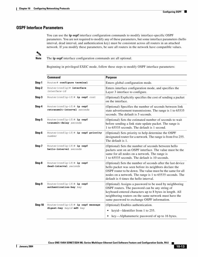
Chapter 10 Configuring Networking ProtocolsConfiguring OSPF
OSPF Interface Parameters
You can use the ip ospf interface configuration commands to modify interface-specific OSPF parameters. You are not required to modify any of these parameters, but some interface parameters (hello interval, dead interval, and authentication key) must be consistent across all routers in an attached network. If you modify these parameters, be sure all routers in the network have compatible values.
Note The ip ospf interface configuration commands are all optional.
Beginning in privileged EXEC mode, follow these steps to modify OSPF interface parameters:
Command Purpose
Step 1 Router# configure terminal Enters global configuration mode.
Step 2 Router(config)# interface interface-id
Enters interface configuration mode, and specifies the Layer 3 interface to configure.
Step 3 Router(config-if)# ip ospf cost (Optional) Explicitly specifies the cost of sending a packet on the interface.
Step 4 Router(config-if)# ip ospf retransmit-interval seconds
(Optional) Specifies the number of seconds between link state advertisement transmissions. The range is 1 to 65535 seconds. The default is 5 seconds.
Step 5 Router(config-if)# ip ospf transmit-delay seconds
(Optional) Sets the estimated number of seconds to wait before sending a link state update packet. The range is 1 to 65535 seconds. The default is 1 second.
Step 6 Router(config-if)# ip ospf priority number
(Optional) Sets priority to help determine the OSPF designated router for a network. The range is from 0 to 255. The default is 1.
Step 7 Router(config-if)# ip ospf hello-interval seconds
(Optional) Sets the number of seconds between hello packets sent on an OSPF interface. The value must be the same for all nodes on a network. The range is 1 to 65535 seconds. The default is 10 seconds.
Step 8 Router(config-if)# ip ospf dead-interval seconds
(Optional) Sets the number of seconds after the last device hello packet was seen before its neighbors declare the OSPF router to be down. The value must be the same for all nodes on a network. The range is 1 to 65535 seconds. The default is 4 times the hello interval.
Step 9 Router(config-if)# ip ospf authentication-key key
(Optional) Assigns a password to be used by neighboring OSPF routers. The password can be any string of keyboard-entered characters up to 8 bytes in length. All neighboring routers on the same network must have the same password to exchange OSPF information.
Step 10 Router(config-if)# ip ospf message digest-key keyid md5 key
(Optional) Enables authentication.
• keyid—Identifier from 1 to 255.
• key—Alphanumeric password of up to 16 bytes.
10-13Cisco ONS 15454 SONET/SDH ML-Series Multilayer Ethernet Card Software Feature and Configuration Guide, R4.6
January 2004
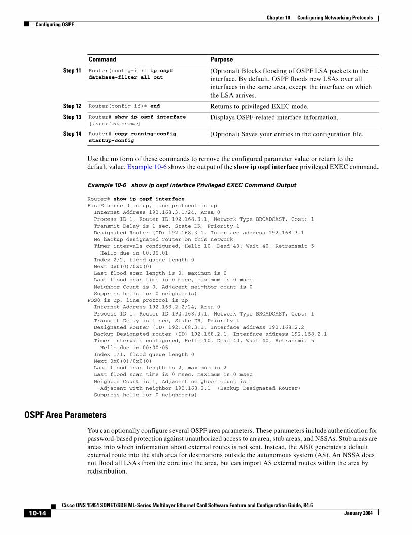
Chapter 10 Configuring Networking ProtocolsConfiguring OSPF
Use the no form of these commands to remove the configured parameter value or return to the default value. Example 10-6 shows the output of the show ip ospf interface privileged EXEC command.
Example 10-6 show ip ospf interface Privileged EXEC Command Output
Router# show ip ospf interfaceFastEthernet0 is up, line protocol is up Internet Address 192.168.3.1/24, Area 0 Process ID 1, Router ID 192.168.3.1, Network Type BROADCAST, Cost: 1 Transmit Delay is 1 sec, State DR, Priority 1 Designated Router (ID) 192.168.3.1, Interface address 192.168.3.1 No backup designated router on this network Timer intervals configured, Hello 10, Dead 40, Wait 40, Retransmit 5 Hello due in 00:00:01 Index 2/2, flood queue length 0 Next 0x0(0)/0x0(0) Last flood scan length is 0, maximum is 0 Last flood scan time is 0 msec, maximum is 0 msec Neighbor Count is 0, Adjacent neighbor count is 0 Suppress hello for 0 neighbor(s)POS0 is up, line protocol is up Internet Address 192.168.2.2/24, Area 0 Process ID 1, Router ID 192.168.3.1, Network Type BROADCAST, Cost: 1 Transmit Delay is 1 sec, State DR, Priority 1 Designated Router (ID) 192.168.3.1, Interface address 192.168.2.2 Backup Designated router (ID) 192.168.2.1, Interface address 192.168.2.1 Timer intervals configured, Hello 10, Dead 40, Wait 40, Retransmit 5 Hello due in 00:00:05 Index 1/1, flood queue length 0 Next 0x0(0)/0x0(0) Last flood scan length is 2, maximum is 2 Last flood scan time is 0 msec, maximum is 0 msec Neighbor Count is 1, Adjacent neighbor count is 1 Adjacent with neighbor 192.168.2.1 (Backup Designated Router) Suppress hello for 0 neighbor(s)
OSPF Area Parameters
You can optionally configure several OSPF area parameters. These parameters include authentication for password-based protection against unauthorized access to an area, stub areas, and NSSAs. Stub areas are areas into which information about external routes is not sent. Instead, the ABR generates a default external route into the stub area for destinations outside the autonomous system (AS). An NSSA does not flood all LSAs from the core into the area, but can import AS external routes within the area by redistribution.
Step 11 Router(config-if)# ip ospf database-filter all out
(Optional) Blocks flooding of OSPF LSA packets to the interface. By default, OSPF floods new LSAs over all interfaces in the same area, except the interface on which the LSA arrives.
Step 12 Router(config-if)# end Returns to privileged EXEC mode.
Step 13 Router# show ip ospf interface [interface-name]
Displays OSPF-related interface information.
Step 14 Router# copy running-config startup-config
(Optional) Saves your entries in the configuration file.
Command Purpose
10-14Cisco ONS 15454 SONET/SDH ML-Series Multilayer Ethernet Card Software Feature and Configuration Guide, R4.6
January 2004

Chapter 10 Configuring Networking ProtocolsConfiguring OSPF
Route summarization is the consolidation of advertised addresses into a single summary route to be advertised by other areas. If network numbers are contiguous, you can use the area range router configuration command to configure the ABR to advertise a summary route that covers all networks in the range.
Note The OSPF area router configuration commands are all optional.
Beginning in privileged EXEC mode, follow these steps to configure area parameters:
Use the no form of these commands to remove the configured parameter value or to return to the default value. Example 10-7 shows the output of the show ip ospf database and the show ip ospf privileged EXEC commands.
Command Purpose
Step 1 Router# configure terminal Enters global configuration mode.
Step 2 Router(config)# router ospf process-id
Enables OSPF routing, and enters router configuration mode.
Step 3 Router(config)# area area-id authentication
(Optional) Allows password-based protection against unauthorized access to the identified area. The identifier can be either a decimal value or an IP address.
Step 4 Router(config)# area area-id authentication message-digest
(Optional) Enables MD5 authentication on the area.
Step 5 Router(config)# area area-id stub [no-summary]
(Optional) Defines an area as a stub area. The no-summary keyword prevents an ABR from sending summary link advertisements into the stub area.
Step 6 Router(config)# area area-id nssa {no-redistribution | default-information-originate | no-summary}
(Optional) Defines an area as a not-so-stubby-area. Every router within the same area must agree that the area is NSSA. Select one of these keywords:
• no-redistribution—Select when the router is an NSSA ABR and you want the redistribute command to import routes into normal areas, but not into the NSSA.
• default-information-originate—Select on an ABR to allow importing type 7 LSAs into the NSSA.
• no-redistribution—Select to not send summary LSAs into the NSSA.
Step 7 Router(config)# area area-id range address-mask
(Optional) Specifies an address range for which a single route is advertised. Use this command only with area border routers.
Step 8 Router(config)# end Returns to privileged EXEC mode.
Step 9 Router# show ip ospf [process-id] Displays information about the OSPF routing process in general or for a specific process ID to verify configuration.
Step 10 Router# copy running-config startup-config
(Optional) Saves your entries in the configuration file.
10-15Cisco ONS 15454 SONET/SDH ML-Series Multilayer Ethernet Card Software Feature and Configuration Guide, R4.6
January 2004
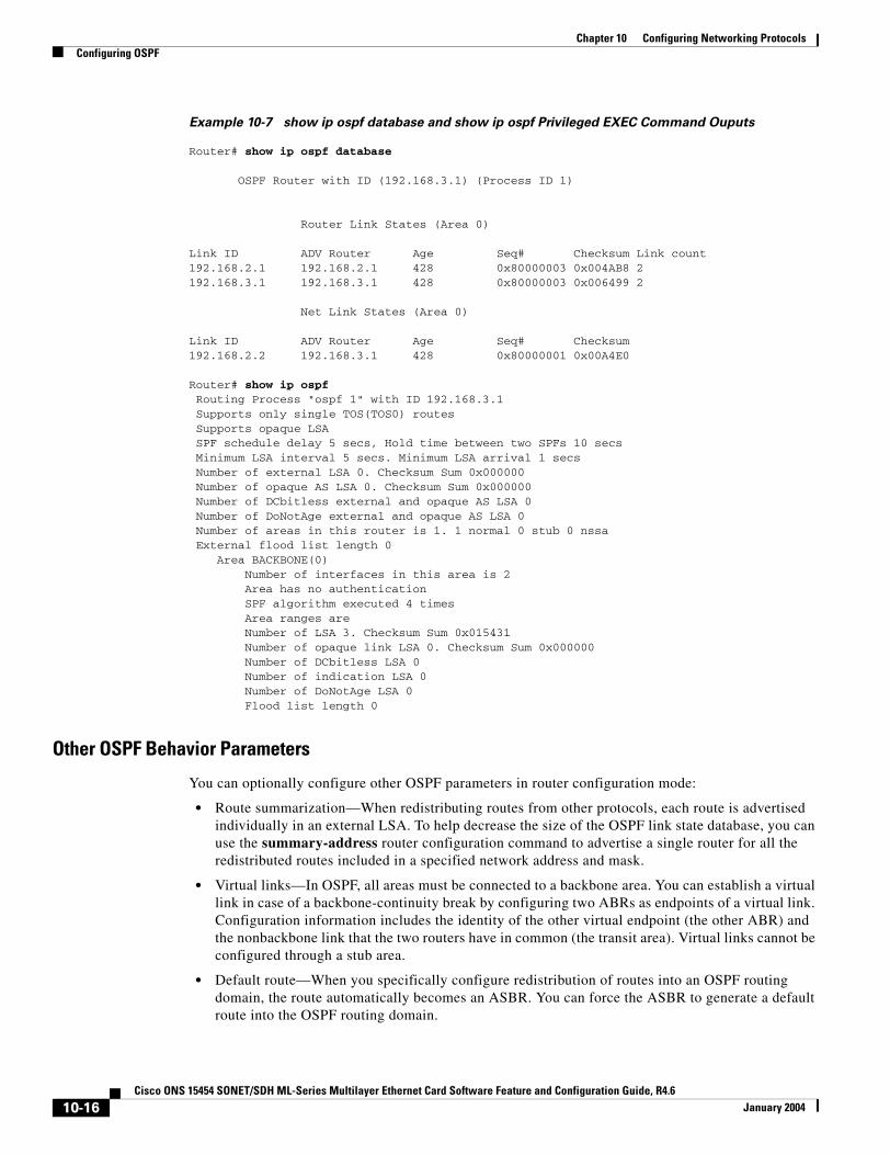
Chapter 10 Configuring Networking ProtocolsConfiguring OSPF
Example 10-7 show ip ospf database and show ip ospf Privileged EXEC Command Ouputs
Router# show ip ospf database
OSPF Router with ID (192.168.3.1) (Process ID 1)
Router Link States (Area 0)
Link ID ADV Router Age Seq# Checksum Link count192.168.2.1 192.168.2.1 428 0x80000003 0x004AB8 2192.168.3.1 192.168.3.1 428 0x80000003 0x006499 2
Net Link States (Area 0)
Link ID ADV Router Age Seq# Checksum192.168.2.2 192.168.3.1 428 0x80000001 0x00A4E0
Router# show ip ospf Routing Process "ospf 1" with ID 192.168.3.1 Supports only single TOS(TOS0) routes Supports opaque LSA SPF schedule delay 5 secs, Hold time between two SPFs 10 secs Minimum LSA interval 5 secs. Minimum LSA arrival 1 secs Number of external LSA 0. Checksum Sum 0x000000 Number of opaque AS LSA 0. Checksum Sum 0x000000 Number of DCbitless external and opaque AS LSA 0 Number of DoNotAge external and opaque AS LSA 0 Number of areas in this router is 1. 1 normal 0 stub 0 nssa External flood list length 0 Area BACKBONE(0) Number of interfaces in this area is 2 Area has no authentication SPF algorithm executed 4 times Area ranges are Number of LSA 3. Checksum Sum 0x015431 Number of opaque link LSA 0. Checksum Sum 0x000000 Number of DCbitless LSA 0 Number of indication LSA 0 Number of DoNotAge LSA 0 Flood list length 0
Other OSPF Behavior Parameters
You can optionally configure other OSPF parameters in router configuration mode:
• Route summarization—When redistributing routes from other protocols, each route is advertised individually in an external LSA. To help decrease the size of the OSPF link state database, you can use the summary-address router configuration command to advertise a single router for all the redistributed routes included in a specified network address and mask.
• Virtual links—In OSPF, all areas must be connected to a backbone area. You can establish a virtual link in case of a backbone-continuity break by configuring two ABRs as endpoints of a virtual link. Configuration information includes the identity of the other virtual endpoint (the other ABR) and the nonbackbone link that the two routers have in common (the transit area). Virtual links cannot be configured through a stub area.
• Default route—When you specifically configure redistribution of routes into an OSPF routing domain, the route automatically becomes an ASBR. You can force the ASBR to generate a default route into the OSPF routing domain.
10-16Cisco ONS 15454 SONET/SDH ML-Series Multilayer Ethernet Card Software Feature and Configuration Guide, R4.6
January 2004
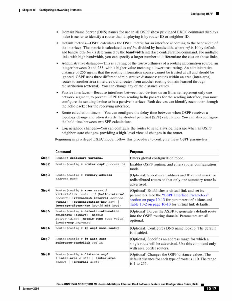
Chapter 10 Configuring Networking ProtocolsConfiguring OSPF
• Domain Name Server (DNS) names for use in all OSPF show privileged EXEC command displays make it easier to identify a router than displaying it by router ID or neighbor ID.
• Default metrics—OSPF calculates the OSPF metric for an interface according to the bandwidth of the interface. The metric is calculated as ref-bw divided by bandwidth, where ref is 10 by default, and bandwidth (bw) is determined by the bandwidth interface configuration command. For multiple links with high bandwidth, you can specify a larger number to differentiate the cost on those links.
• Administrative distance—This is a rating of the trustworthiness of a routing information source, an integer between 0 and 255, with a higher value meaning a lower trust rating. An administrative distance of 255 means that the routing information source cannot be trusted at all and should be ignored. OSPF uses three different administrative distances: routes within an area (intra-area), routes to another area (interarea), and routes from another routing domain learned through redistribution (external). You can change any of the distance values.
• Passive interfaces—Because interfaces between two devices on an Ethernet represent only one network segment, to prevent OSPF from sending hello packets for the sending interface, you must configure the sending device to be a passive interface. Both devices can identify each other through the hello packet for the receiving interface.
• Route calculation timers—You can configure the delay time between when OSPF receives a topology change and when it starts the shortest path first (SPF) calculation. You can also configure the hold time between two SPF calculations.
• Log neighbor changes—You can configure the router to send a syslog message when an OSPF neighbor state changes, providing a high-level view of changes in the router.
Beginning in privileged EXEC mode, follow this procedure to configure these OSPF parameters:
Command Purpose
Step 1 Router# configure terminal Enters global configuration mode.
Step 2 Router(config)# router ospf process-id Enables OSPF routing, and enters router configuration mode.
Step 3 Router(config)# summary-address address-mask
(Optional) Specifies an address and IP subnet mask for redistributed routes so that only one summary route is advertised.
Step 4 Router(config)# area area-id virtual-link router-id [hello-interval seconds] [retransmit-interval seconds] [trans] {[authentication-key key] | [message-digest-key key-id md5 key]}
(Optional) Establishes a virtual link and set its parameters. See the “OSPF Interface Parameters” section on page 10-13 for parameter definitions and Table 10-2 on page 10-10 for virtual link defaults.
Step 5 Router(config)# default-information originate [always] [metric metric-value] [metric-type type-value] [route-map map-name]
(Optional) Forces the ASBR to generate a default route into the OSPF routing domain. Parameters are all optional.
Step 6 Router(config)# ip ospf name-lookup (Optional) Configures DNS name lookup. The default is disabled.
Step 7 Router(config)# ip auto-cost reference-bandwidth ref-bw
(Optional) Specifies an address range for which a single route will be advertised. Use this command only with area border routers.
Step 8 Router(config)# distance ospf {[inter-area dist1] | [inter-area dist2] | [external dist3]}
(Optional) Changes the OSPF distance values. The default distance for each type of route is 110. The range is 1 to 255.
10-17Cisco ONS 15454 SONET/SDH ML-Series Multilayer Ethernet Card Software Feature and Configuration Guide, R4.6
January 2004
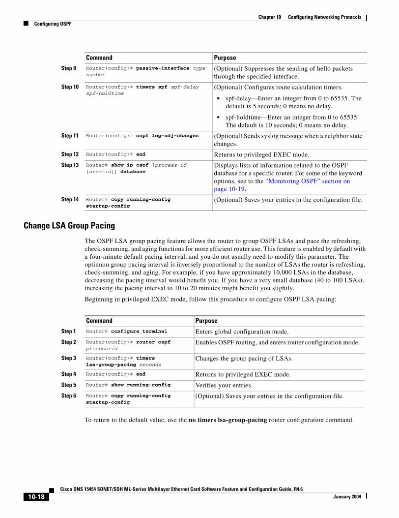
Chapter 10 Configuring Networking ProtocolsConfiguring OSPF
Change LSA Group Pacing
The OSPF LSA group pacing feature allows the router to group OSPF LSAs and pace the refreshing, check-summing, and aging functions for more efficient router use. This feature is enabled by default with a four-minute default pacing interval, and you do not usually need to modify this parameter. The optimum group pacing interval is inversely proportional to the number of LSAs the router is refreshing, check-summing, and aging. For example, if you have approximately 10,000 LSAs in the database, decreasing the pacing interval would benefit you. If you have a very small database (40 to 100 LSAs), increasing the pacing interval to 10 to 20 minutes might benefit you slightly.
Beginning in privileged EXEC mode, follow this procedure to configure OSPF LSA pacing:
To return to the default value, use the no timers lsa-group-pacing router configuration command.
Step 9 Router(config)# passive-interface type number
(Optional) Suppresses the sending of hello packets through the specified interface.
Step 10 Router(config)# timers spf spf-delay spf-holdtime
(Optional) Configures route calculation timers.
• spf-delay—Enter an integer from 0 to 65535. The default is 5 seconds; 0 means no delay.
• spf-holdtime—Enter an integer from 0 to 65535. The default is 10 seconds; 0 means no delay.
Step 11 Router(config)# ospf log-adj-changes (Optional) Sends syslog message when a neighbor state changes.
Step 12 Router(config)# end Returns to privileged EXEC mode.
Step 13 Router# show ip ospf [process-id [area-id]] database
Displays lists of information related to the OSPF database for a specific router. For some of the keyword options, see to the “Monitoring OSPF” section on page 10-19.
Step 14 Router# copy running-config startup-config
(Optional) Saves your entries in the configuration file.
Command Purpose
Command Purpose
Step 1 Router# configure terminal Enters global configuration mode.
Step 2 Router(config)# router ospf process-id
Enables OSPF routing, and enters router configuration mode.
Step 3 Router(config)# timers lsa-group-pacing seconds
Changes the group pacing of LSAs.
Step 4 Router(config)# end Returns to privileged EXEC mode.
Step 5 Router# show running-config Verifies your entries.
Step 6 Router# copy running-config startup-config
(Optional) Saves your entries in the configuration file.
10-18Cisco ONS 15454 SONET/SDH ML-Series Multilayer Ethernet Card Software Feature and Configuration Guide, R4.6
January 2004
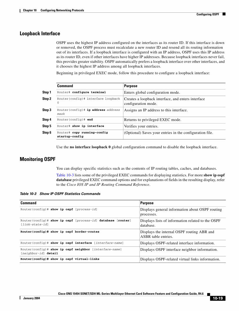
Chapter 10 Configuring Networking ProtocolsConfiguring OSPF
Loopback Interface
OSPF uses the highest IP address configured on the interfaces as its router ID. If this interface is down or removed, the OSPF process must recalculate a new router ID and resend all its routing information out of its interfaces. If a loopback interface is configured with an IP address, OSPF uses this IP address as its router ID, even if other interfaces have higher IP addresses. Because loopback interfaces never fail, this provides greater stability. OSPF automatically prefers a loopback interface over other interfaces, and it chooses the highest IP address among all loopback interfaces.
Beginning in privileged EXEC mode, follow this procedure to configure a loopback interface:
Use the no interface loopback 0 global configuration command to disable the loopback interface.
Monitoring OSPF
You can display specific statistics such as the contents of IP routing tables, caches, and databases.
Table 10-3 lists some of the privileged EXEC commands for displaying statistics. For more show ip ospf database privileged EXEC command options and for explanations of fields in the resulting display, refer to the Cisco IOS IP and IP Routing Command Reference.
Command Purpose
Step 1 Router# configure terminal Enters global configuration mode.
Step 2 Router(config)# interface loopback 0
Creates a loopback interface, and enters interface configuration mode.
Step 3 Router(config)# ip address address mask
Assigns an IP address to this interface.
Step 4 Router(config)# end Returns to privileged EXEC mode.
Step 5 Router# show ip interface Verifies your entries.
Step 6 Router# copy running-config startup-config
(Optional) Saves your entries in the configuration file.
Table 10-3 Show IP OSPF Statistics Commands
Command PurposeRouter(config)# show ip ospf [process-id] Displays general information about OSPF routing
processes.
Router(config)# show ip ospf [process-id] database [router] [link-state-id]
Displays lists of information related to the OSPF database.
Router(config)# show ip ospf border-routes Displays the internal OSPF routing ABR and ASBR table entries.
Router(config)# show ip ospf interface [interface-name] Displays OSPF-related interface information.
Router(config)# show ip ospf neighbor [interface-name] [neighbor-id] detail
Displays OSPF interface neighbor information.
Router(config)# show ip ospf virtual-links Displays OSPF-related virtual links information.
10-19Cisco ONS 15454 SONET/SDH ML-Series Multilayer Ethernet Card Software Feature and Configuration Guide, R4.6
January 2004
Chapter 10 Configuring Networking ProtocolsConfiguring EIGRP
Configuring EIGRPEnhanced IGRP (EIGRP) is a Cisco proprietary enhanced version of the Interior Gateway Routing Protocol (IGRP). Enhanced IGRP uses the same distance vector algorithm and distance information as IGRP; however, the convergence properties and the operating efficiency of Enhanced IGRP are significantly improved.
The convergence technology employs an algorithm referred to as the Diffusing Update Algorithm (DUAL), which guarantees loop-free operation at every instant throughout a route computation and allows all devices involved in a topology change to synchronize at the same time. Routers that are not affected by topology changes are not involved in recomputations.
IP EIGRP provides increased network width. With RIP, the largest possible width of your network is 15 hops. When IGRP is enabled, the largest possible width is 224 hops. Because the EIGRP metric is large enough to support thousands of hops, the only barrier to expanding the network is the transport-layer hop counter. EIGRP increments the transport control field only when an IP packet has traversed 15 routers and the next hop to the destination was learned through EIGRP. When a RIP route is used as the next hop to the destination, the transport control field is incremented as usual.
EIGRP offers the following features:
• Fast convergence
• Incremental updates when the state of a destination changes, instead of sending the entire contents of the routing table, minimizing the bandwidth required for EIGRP packets
• Less CPU usage than IGRP because full update packets do not need to be processed each time they are received
• Protocol-independent neighbor discovery mechanism to learn about neighboring routers
• Variable-length subnet masks (VLSMs)
• Arbitrary route summarization
• EIGRP scales to large networks
EIGRP has four basic components:
• Neighbor discovery and recovery is the process that routers use to dynamically learn of other routers on their directly attached networks. Routers must also discover when their neighbors become unreachable or inoperative. Neighbor discovery and recovery is achieved with low overhead by periodically sending small hello packets. As long as hello packets are received, the Cisco IOS software can determine that a neighbor is alive and functioning. When this status is determined, the neighboring routers can exchange routing information.
• The reliable transport protocol is responsible for guaranteed, ordered delivery of EIGRP packets to all neighbors. It supports intermixed transmission of multicast and unicast packets. Some EIGRP packets must be sent reliably, and others need not be. For efficiency, reliability is provided only when necessary. For example, on a multiaccess network that has multicast capabilities (such as Ethernet), it is not necessary to send hellos reliably to all neighbors individually. Therefore, EIGRP sends a single multicast hello with an indication in the packet informing the receivers that the packet need not be acknowledged. Other types of packets (such as updates) require acknowledgment, which is shown in the packet. The reliable transport has a provision to send multicast packets quickly when there are unacknowledged packets pending. Doing so helps ensure that convergence time remains low in the presence of varying speed links.
• The DUAL finite state machine embodies the decision process for all route computations. It tracks all routes advertised by all neighbors. DUAL uses the distance information (known as a metric) to select efficient, loop-free paths. DUAL selects routes to be inserted into a routing table based on feasible successors. A successor is a neighboring router used for packet forwarding that has a
10-20Cisco ONS 15454 SONET/SDH ML-Series Multilayer Ethernet Card Software Feature and Configuration Guide, R4.6
January 2004
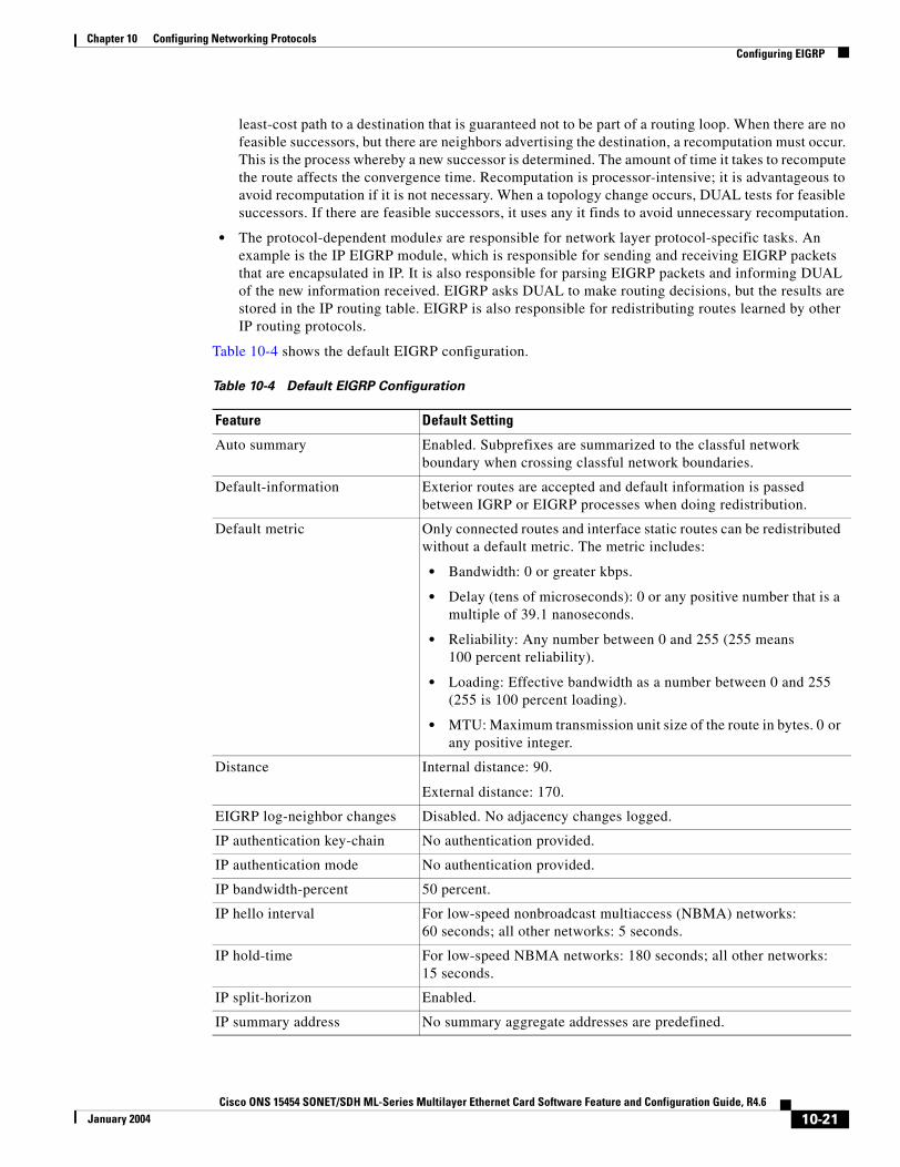
Chapter 10 Configuring Networking ProtocolsConfiguring EIGRP
least-cost path to a destination that is guaranteed not to be part of a routing loop. When there are no feasible successors, but there are neighbors advertising the destination, a recomputation must occur. This is the process whereby a new successor is determined. The amount of time it takes to recompute the route affects the convergence time. Recomputation is processor-intensive; it is advantageous to avoid recomputation if it is not necessary. When a topology change occurs, DUAL tests for feasible successors. If there are feasible successors, it uses any it finds to avoid unnecessary recomputation.
• The protocol-dependent modules are responsible for network layer protocol-specific tasks. An example is the IP EIGRP module, which is responsible for sending and receiving EIGRP packets that are encapsulated in IP. It is also responsible for parsing EIGRP packets and informing DUAL of the new information received. EIGRP asks DUAL to make routing decisions, but the results are stored in the IP routing table. EIGRP is also responsible for redistributing routes learned by other IP routing protocols.
Table 10-4 shows the default EIGRP configuration.
Table 10-4 Default EIGRP Configuration
Feature Default Setting
Auto summary Enabled. Subprefixes are summarized to the classful network boundary when crossing classful network boundaries.
Default-information Exterior routes are accepted and default information is passed between IGRP or EIGRP processes when doing redistribution.
Default metric Only connected routes and interface static routes can be redistributed without a default metric. The metric includes:
• Bandwidth: 0 or greater kbps.
• Delay (tens of microseconds): 0 or any positive number that is a multiple of 39.1 nanoseconds.
• Reliability: Any number between 0 and 255 (255 means 100 percent reliability).
• Loading: Effective bandwidth as a number between 0 and 255 (255 is 100 percent loading).
• MTU: Maximum transmission unit size of the route in bytes. 0 or any positive integer.
Distance Internal distance: 90.
External distance: 170.
EIGRP log-neighbor changes Disabled. No adjacency changes logged.
IP authentication key-chain No authentication provided.
IP authentication mode No authentication provided.
IP bandwidth-percent 50 percent.
IP hello interval For low-speed nonbroadcast multiaccess (NBMA) networks: 60 seconds; all other networks: 5 seconds.
IP hold-time For low-speed NBMA networks: 180 seconds; all other networks: 15 seconds.
IP split-horizon Enabled.
IP summary address No summary aggregate addresses are predefined.
10-21Cisco ONS 15454 SONET/SDH ML-Series Multilayer Ethernet Card Software Feature and Configuration Guide, R4.6
January 2004
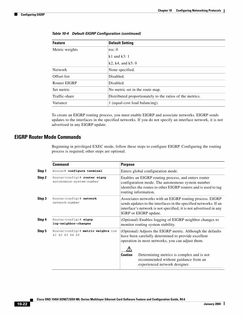
Chapter 10 Configuring Networking ProtocolsConfiguring EIGRP
To create an EIGRP routing process, you must enable EIGRP and associate networks. EIGRP sends updates to the interfaces in the specified networks. If you do not specify an interface network, it is not advertised in any EIGRP update.
EIGRP Router Mode Commands
Beginning in privileged EXEC mode, follow these steps to configure EIGRP. Configuring the routing process is required; other steps are optional.
Metric weights tos: 0
k1 and k3: 1
k2, k4, and k5: 0
Network None specified.
Offset-list Disabled.
Router EIGRP Disabled.
Set metric No metric set in the route map.
Traffic-share Distributed proportionately to the ratios of the metrics.
Variance 1 (equal-cost load balancing).
Table 10-4 Default EIGRP Configuration (continued)
Feature Default Setting
Command Purpose
Step 1 Router# configure terminal Enters global configuration mode.
Step 2 Router(config)# router eigrp autonomous-system-number
Enables an EIGRP routing process, and enters router configuration mode. The autonomous system number identifies the routes to other EIGRP routers and is used to tag routing information.
Step 3 Router(config)# network network-number
Associates networks with an EIGRP routing process. EIGRP sends updates to the interfaces in the specified networks. If an interface’s network is not specified, it is not advertised in any IGRP or EIGRP update.
Step 4 Router(config)# eigrp log-neighbor-changes
(Optional) Enables logging of EIGRP neighbor changes to monitor routing system stability.
Step 5 Router(config)# metric weights tos k1 k2 k3 k4 k5
(Optional) Adjusts the EIGRP metric. Although the defaults have been carefully determined to provide excellent operation in most networks, you can adjust them.
Caution Determining metrics is complex and is not recommended without guidance from an experienced network designer.
10-22Cisco ONS 15454 SONET/SDH ML-Series Multilayer Ethernet Card Software Feature and Configuration Guide, R4.6
January 2004
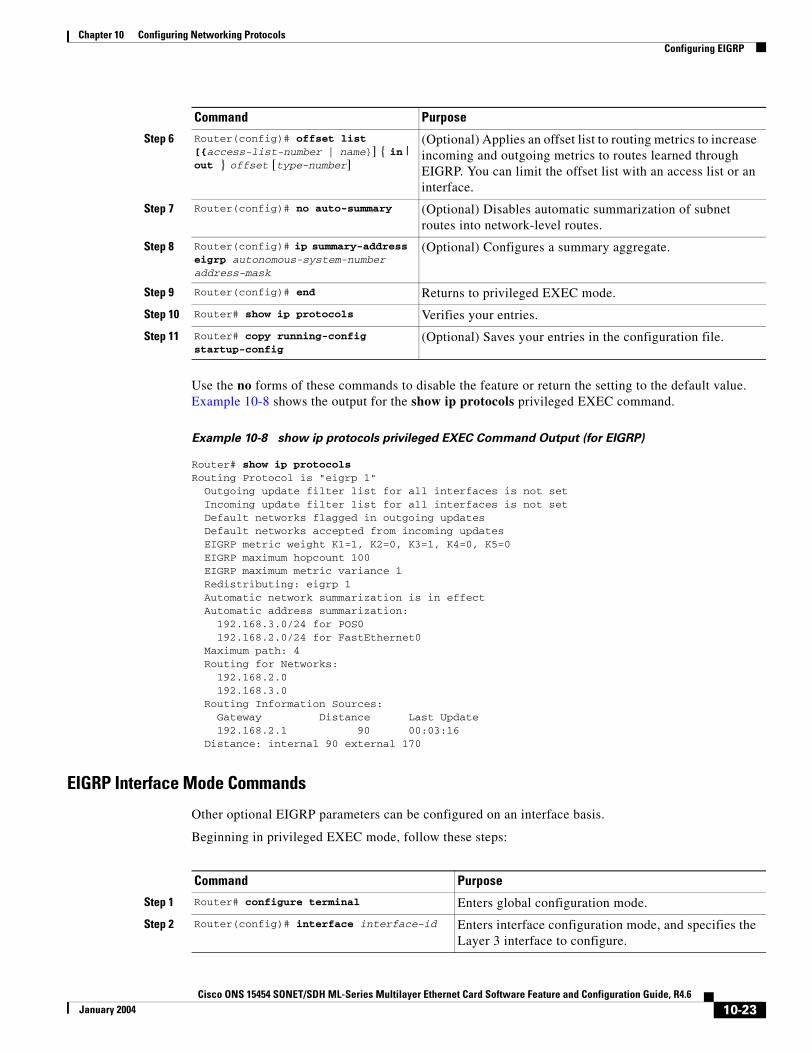
Chapter 10 Configuring Networking ProtocolsConfiguring EIGRP
Use the no forms of these commands to disable the feature or return the setting to the default value. Example 10-8 shows the output for the show ip protocols privileged EXEC command.
Example 10-8 show ip protocols privileged EXEC Command Output (for EIGRP)
Router# show ip protocolsRouting Protocol is "eigrp 1" Outgoing update filter list for all interfaces is not set Incoming update filter list for all interfaces is not set Default networks flagged in outgoing updates Default networks accepted from incoming updates EIGRP metric weight K1=1, K2=0, K3=1, K4=0, K5=0 EIGRP maximum hopcount 100 EIGRP maximum metric variance 1 Redistributing: eigrp 1 Automatic network summarization is in effect Automatic address summarization: 192.168.3.0/24 for POS0 192.168.2.0/24 for FastEthernet0 Maximum path: 4 Routing for Networks: 192.168.2.0 192.168.3.0 Routing Information Sources: Gateway Distance Last Update 192.168.2.1 90 00:03:16 Distance: internal 90 external 170
EIGRP Interface Mode Commands
Other optional EIGRP parameters can be configured on an interface basis.
Beginning in privileged EXEC mode, follow these steps:
Step 6 Router(config)# offset list [{access-list-number | name}] { in | out } offset [type-number]
(Optional) Applies an offset list to routing metrics to increase incoming and outgoing metrics to routes learned through EIGRP. You can limit the offset list with an access list or an interface.
Step 7 Router(config)# no auto-summary (Optional) Disables automatic summarization of subnet routes into network-level routes.
Step 8 Router(config)# ip summary-address eigrp autonomous-system-number address-mask
(Optional) Configures a summary aggregate.
Step 9 Router(config)# end Returns to privileged EXEC mode.
Step 10 Router# show ip protocols Verifies your entries.
Step 11 Router# copy running-config startup-config
(Optional) Saves your entries in the configuration file.
Command Purpose
Command Purpose
Step 1 Router# configure terminal Enters global configuration mode.
Step 2 Router(config)# interface interface-id Enters interface configuration mode, and specifies the Layer 3 interface to configure.
10-23Cisco ONS 15454 SONET/SDH ML-Series Multilayer Ethernet Card Software Feature and Configuration Guide, R4.6
January 2004
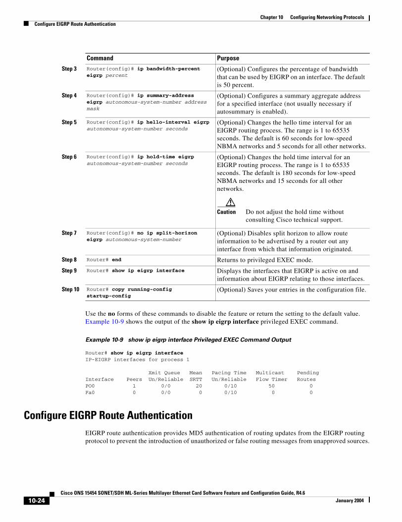
Chapter 10 Configuring Networking ProtocolsConfigure EIGRP Route Authentication
Use the no forms of these commands to disable the feature or return the setting to the default value. Example 10-9 shows the output of the show ip eigrp interface privileged EXEC command.
Example 10-9 show ip eigrp interface Privileged EXEC Command Output
Router# show ip eigrp interfaceIP-EIGRP interfaces for process 1
Xmit Queue Mean Pacing Time Multicast PendingInterface Peers Un/Reliable SRTT Un/Reliable Flow Timer RoutesPO0 1 0/0 20 0/10 50 0Fa0 0 0/0 0 0/10 0 0
Configure EIGRP Route AuthenticationEIGRP route authentication provides MD5 authentication of routing updates from the EIGRP routing protocol to prevent the introduction of unauthorized or false routing messages from unapproved sources.
Step 3 Router(config)# ip bandwidth-percent eigrp percent
(Optional) Configures the percentage of bandwidth that can be used by EIGRP on an interface. The default is 50 percent.
Step 4 Router(config)# ip summary-address eigrp autonomous-system-number address mask
(Optional) Configures a summary aggregate address for a specified interface (not usually necessary if autosummary is enabled).
Step 5 Router(config)# ip hello-interval eigrp autonomous-system-number seconds
(Optional) Changes the hello time interval for an EIGRP routing process. The range is 1 to 65535 seconds. The default is 60 seconds for low-speed NBMA networks and 5 seconds for all other networks.
Step 6 Router(config)# ip hold-time eigrp autonomous-system-number seconds
(Optional) Changes the hold time interval for an EIGRP routing process. The range is 1 to 65535 seconds. The default is 180 seconds for low-speed NBMA networks and 15 seconds for all other networks.
Caution Do not adjust the hold time without consulting Cisco technical support.
Step 7 Router(config)# no ip split-horizon eigrp autonomous-system-number
(Optional) Disables split horizon to allow route information to be advertised by a router out any interface from which that information originated.
Step 8 Router# end Returns to privileged EXEC mode.
Step 9 Router# show ip eigrp interface Displays the interfaces that EIGRP is active on and information about EIGRP relating to those interfaces.
Step 10 Router# copy running-config startup-config
(Optional) Saves your entries in the configuration file.
Command Purpose
10-24Cisco ONS 15454 SONET/SDH ML-Series Multilayer Ethernet Card Software Feature and Configuration Guide, R4.6
January 2004

Chapter 10 Configuring Networking ProtocolsConfigure EIGRP Route Authentication
Beginning in privileged EXEC mode, follow these steps to enable authentication:
Use the no forms of these commands to disable the feature or to return the setting to the default value.
Monitoring and Maintaining EIGRP
You can delete neighbors from the neighbor table. You can also display various EIGRP routing statistics. Table 10-5 lists the privileged EXEC commands for deleting neighbors and displaying statistics. For explanations of fields in the resulting display, refer to the Cisco IOS IP and IP Routing Command Reference publication.
Command Purpose
Step 1 Router# configure terminal Enters global configuration mode.
Step 2 Router(config)# interface interface-id Enters interface configuration mode, and specifies the Layer 3 interface to configure.
Step 3 Router(config-if)# ip authentication mode eigrp autonomous-system md5
Enables MD5 authentication in IP EIGRP packets.
Step 4 Router(config-if)# ip authentication key-chain eigrp autonomous-system key-chain
Enables authentication of IP EIGRP packets.
Step 5 Router(config-if)# exit Returns to global configuration mode.
Step 6 Router(config)# key chain name-of-chain Identifies a key chain and enter key-chain configuration mode. Match the name configured in Step 4.
Step 7 Router(config)# key number In key-chain configuration mode, identifies the key number.
Step 8 Router(config)# key-string text In key-chain key configuration mode, identifies the key string.
Step 9 Router(config)# accept-lifetime start-time {infinite | end-time | duration seconds}
(Optional) Specifies the time period during which the key can be received.
The start-time and end-time syntax can be either hh:mm:ss Month date year or hh:mm:ss date Month year. The default start-time (and earliest acceptable day) is January 1, 1993. The default end-time and duration is infinite.
Step 10 Router(config)# send-lifetime start-time {infinite | end-time | duration seconds}
(Optional) Specifies the time period during which the key can be sent.
The start-time and end-time syntax can be either hh:mm:ss Month day year or hh:mm:ss day Month year. The default start-time (and earliest acceptable day) is January 1, 1993. The default end-time and duration is infinite.
Step 11 Router(config)# end Returns to privileged EXEC mode.
Step 12 Router# show key chain Displays authentication key information.
Step 13 Router# copy running-config startup-config
(Optional) Saves your entries in the configuration file.
10-25Cisco ONS 15454 SONET/SDH ML-Series Multilayer Ethernet Card Software Feature and Configuration Guide, R4.6
January 2004

Chapter 10 Configuring Networking ProtocolsConfigure EIGRP Route Authentication
Example 10-10 shows the output of the show ip eigrp interface privileged EXEC command. Example 10-11 shows the output of the show ip eigrp neighbors privileged EXEC command. Example 10-12 shows the output of the show ip eigrp topology privileged EXEC command. Example 10-13 shows the output of the show ip eigrp traffic privileged EXEC command.
Example 10-10 show ip eigrp interface Privileged EXEC Command Output
Router# show ip eigrp interfaceIP-EIGRP interfaces for process 1
Xmit Queue Mean Pacing Time Multicast PendingInterface Peers Un/Reliable SRTT Un/Reliable Flow Timer RoutesPO0 1 0/0 20 0/10 50 0Fa0 0 0/0 0 0/10 0 0
Example 10-11 show ip eigrp neighbors Privileged EXEC Command Output
Router# show ip eigrp neighborsIP-EIGRP neighbors for process 1H Address Interface Hold Uptime SRTT RTO Q Seq Type (sec) (ms) Cnt Num0 192.168.2.1 PO0 13 00:08:15 20 200 0 2
Example 10-12 show ip eigrp topology Privileged EXEC Command Output
Router# show ip eigrp topologyIP-EIGRP Topology Table for AS(1)/ID(192.168.3.1)
Codes: P - Passive, A - Active, U - Update, Q - Query, R - Reply, r - reply Status, s - sia Status
P 192.168.1.0/24, 1 successors, FD is 30720 via 192.168.2.1 (30720/28160), POS0P 192.168.2.0/24, 1 successors, FD is 10752 via Connected, POS0P 192.168.3.0/24, 1 successors, FD is 28160 via Connected, FastEthernet0
Table 10-5 IP EIGRP Clear and Show Commands
Command Purpose
Router# clear ip eigrp neighbors {ip-address | interface}
Deletes neighbors from the neighbor table.
Router# show ip eigrp interface [interface] [as-number]
Displays information about interfaces configured for EIGRP.
Router# show ip eigrp neighbors [type-number]
Displays EIGRP discovered neighbors.
Router# show ip eigrp topology {autonomous-system-number | [ip-address] mask}
Displays the EIGRP topology table for a given process.
Router# show ip eigrp traffic [autonomous-system-number]
Displays the number of packets sent and received for all or a specified EIGRP process.
10-26Cisco ONS 15454 SONET/SDH ML-Series Multilayer Ethernet Card Software Feature and Configuration Guide, R4.6
January 2004
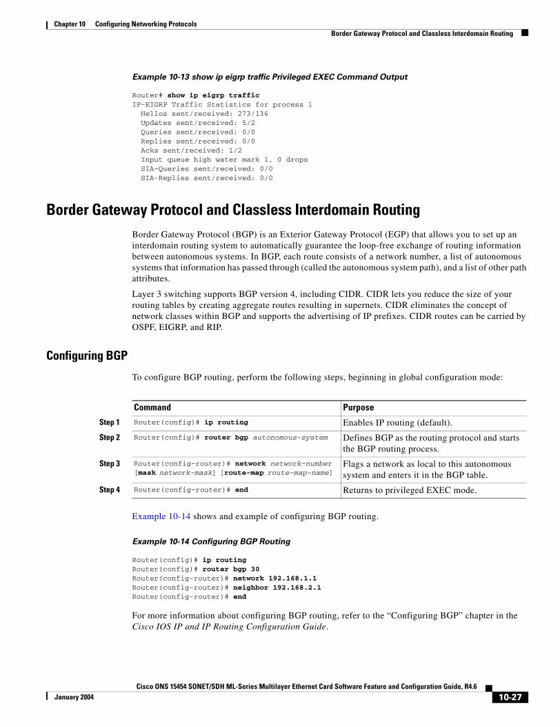
Chapter 10 Configuring Networking ProtocolsBorder Gateway Protocol and Classless Interdomain Routing
Example 10-13 show ip eigrp traffic Privileged EXEC Command Output
Router# show ip eigrp trafficIP-EIGRP Traffic Statistics for process 1 Hellos sent/received: 273/136 Updates sent/received: 5/2 Queries sent/received: 0/0 Replies sent/received: 0/0 Acks sent/received: 1/2 Input queue high water mark 1, 0 drops SIA-Queries sent/received: 0/0 SIA-Replies sent/received: 0/0
Border Gateway Protocol and Classless Interdomain RoutingBorder Gateway Protocol (BGP) is an Exterior Gateway Protocol (EGP) that allows you to set up an interdomain routing system to automatically guarantee the loop-free exchange of routing information between autonomous systems. In BGP, each route consists of a network number, a list of autonomous systems that information has passed through (called the autonomous system path), and a list of other path attributes.
Layer 3 switching supports BGP version 4, including CIDR. CIDR lets you reduce the size of your routing tables by creating aggregate routes resulting in supernets. CIDR eliminates the concept of network classes within BGP and supports the advertising of IP prefixes. CIDR routes can be carried by OSPF, EIGRP, and RIP.
Configuring BGP
To configure BGP routing, perform the following steps, beginning in global configuration mode:
Example 10-14 shows and example of configuring BGP routing.
Example 10-14 Configuring BGP Routing
Router(config)# ip routingRouter(config)# router bgp 30Router(config-router)# network 192.168.1.1Router(config-router)# neighbor 192.168.2.1Router(config-router)# end
For more information about configuring BGP routing, refer to the “Configuring BGP” chapter in the Cisco IOS IP and IP Routing Configuration Guide.
Command Purpose
Step 1 Router(config)# ip routing Enables IP routing (default).
Step 2 Router(config)# router bgp autonomous-system Defines BGP as the routing protocol and starts the BGP routing process.
Step 3 Router(config-router)# network network-number [mask network-mask] [route-map route-map-name]
Flags a network as local to this autonomous system and enters it in the BGP table.
Step 4 Router(config-router)# end Returns to privileged EXEC mode.
10-27Cisco ONS 15454 SONET/SDH ML-Series Multilayer Ethernet Card Software Feature and Configuration Guide, R4.6
January 2004
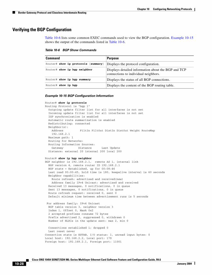
Chapter 10 Configuring Networking ProtocolsBorder Gateway Protocol and Classless Interdomain Routing
Verifying the BGP Configuration
Table 10-6 lists some common EXEC commands used to view the BGP configuration. Example 10-15 shows the output of the commands listed in Table 10-6.
Example 10-15 BGP Configuration Information
Router# show ip protocolsRouting Protocol is "bgp 1" Outgoing update filter list for all interfaces is not set Incoming update filter list for all interfaces is not set IGP synchronization is enabled Automatic route summarization is enabled Redistributing: connected Neighbor(s): Address FiltIn FiltOut DistIn DistOut Weight RouteMap 192.168.2.1 Maximum path: 1 Routing for Networks: Routing Information Sources: Gateway Distance Last Update Distance: external 20 internal 200 local 200
Router# show ip bgp neighborBGP neighbor is 192.168.2.1, remote AS 1, internal link BGP version 4, remote router ID 192.168.2.1 BGP state = Established, up for 00:08:46 Last read 00:00:45, hold time is 180, keepalive interval is 60 seconds Neighbor capabilities: Route refresh: advertised and received(new) Address family IPv4 Unicast: advertised and received Received 13 messages, 0 notifications, 0 in queue Sent 13 messages, 0 notifications, 0 in queue Route refresh request: received 0, sent 0 Default minimum time between advertisement runs is 5 seconds
For address family: IPv4 Unicast BGP table version 3, neighbor version 3 Index 1, Offset 0, Mask 0x2 2 accepted prefixes consume 72 bytes Prefix advertised 2, suppressed 0, withdrawn 0 Number of NLRIs in the update sent: max 2, min 0
Connections established 1; dropped 0 Last reset neverConnection state is ESTAB, I/O status: 1, unread input bytes: 0Local host: 192.168.2.2, Local port: 179Foreign host: 192.168.2.1, Foreign port: 11001
Table 10-6 BGP Show Commands
Command PurposeRouter# show ip protocols [summary] Displays the protocol configuration.
Router# show ip bgp neighbor Displays detailed information about the BGP and TCP connections to individual neighbors.
Router# show ip bgp summary Displays the status of all BGP connections.
Router# show ip bgp Displays the content of the BGP routing table.
10-28Cisco ONS 15454 SONET/SDH ML-Series Multilayer Ethernet Card Software Feature and Configuration Guide, R4.6
January 2004
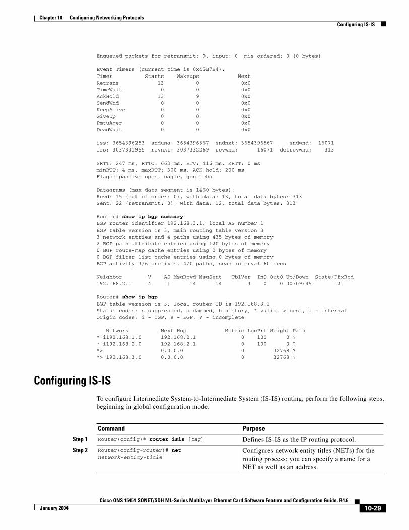
Chapter 10 Configuring Networking ProtocolsConfiguring IS-IS
Enqueued packets for retransmit: 0, input: 0 mis-ordered: 0 (0 bytes)
Event Timers (current time is 0x45B7B4):Timer Starts Wakeups NextRetrans 13 0 0x0TimeWait 0 0 0x0AckHold 13 9 0x0SendWnd 0 0 0x0KeepAlive 0 0 0x0GiveUp 0 0 0x0PmtuAger 0 0 0x0DeadWait 0 0 0x0
iss: 3654396253 snduna: 3654396567 sndnxt: 3654396567 sndwnd: 16071irs: 3037331955 rcvnxt: 3037332269 rcvwnd: 16071 delrcvwnd: 313
SRTT: 247 ms, RTTO: 663 ms, RTV: 416 ms, KRTT: 0 msminRTT: 4 ms, maxRTT: 300 ms, ACK hold: 200 msFlags: passive open, nagle, gen tcbs
Datagrams (max data segment is 1460 bytes):Rcvd: 15 (out of order: 0), with data: 13, total data bytes: 313Sent: 22 (retransmit: 0), with data: 12, total data bytes: 313
Router# show ip bgp summaryBGP router identifier 192.168.3.1, local AS number 1BGP table version is 3, main routing table version 33 network entries and 4 paths using 435 bytes of memory2 BGP path attribute entries using 120 bytes of memory0 BGP route-map cache entries using 0 bytes of memory0 BGP filter-list cache entries using 0 bytes of memoryBGP activity 3/6 prefixes, 4/0 paths, scan interval 60 secs
Neighbor V AS MsgRcvd MsgSent TblVer InQ OutQ Up/Down State/PfxRcd192.168.2.1 4 1 14 14 3 0 0 00:09:45 2
Router# show ip bgpBGP table version is 3, local router ID is 192.168.3.1Status codes: s suppressed, d damped, h history, * valid, > best, i - internalOrigin codes: i - IGP, e - EGP, ? - incomplete
Network Next Hop Metric LocPrf Weight Path* i192.168.1.0 192.168.2.1 0 100 0 ?* i192.168.2.0 192.168.2.1 0 100 0 ?*> 0.0.0.0 0 32768 ?*> 192.168.3.0 0.0.0.0 0 32768 ?
Configuring IS-ISTo configure Intermediate System-to-Intermediate System (IS-IS) routing, perform the following steps, beginning in global configuration mode:
Command Purpose
Step 1 Router(config)# router isis [tag] Defines IS-IS as the IP routing protocol.
Step 2 Router(config-router)# net network-entity-title
Configures network entity titles (NETs) for the routing process; you can specify a name for a NET as well as an address.
10-29Cisco ONS 15454 SONET/SDH ML-Series Multilayer Ethernet Card Software Feature and Configuration Guide, R4.6
January 2004
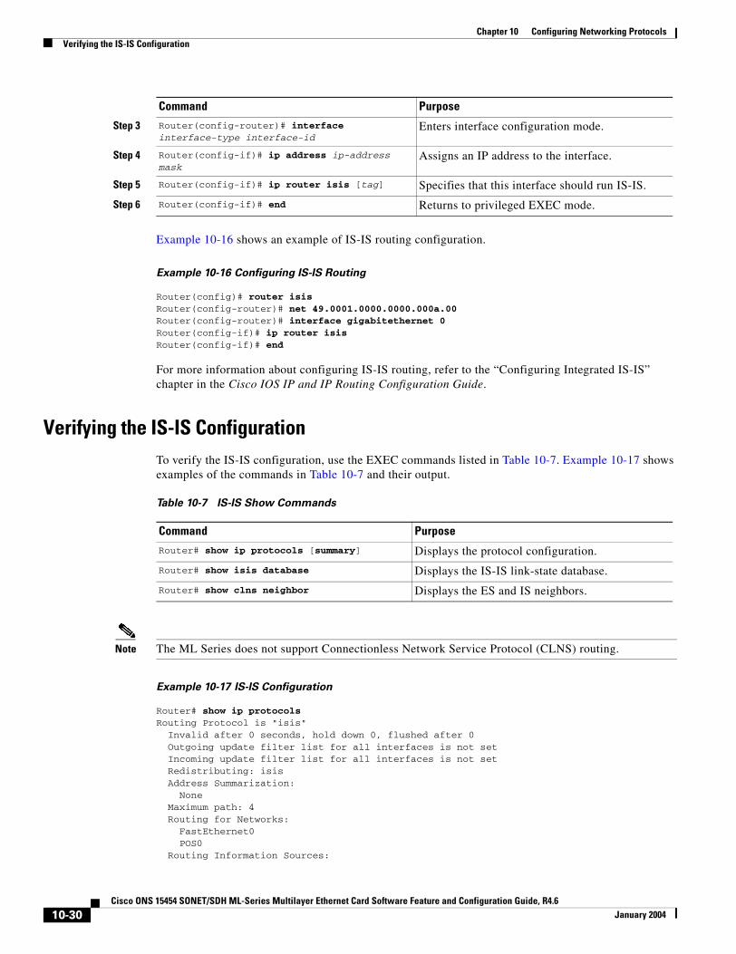
Chapter 10 Configuring Networking ProtocolsVerifying the IS-IS Configuration
Example 10-16 shows an example of IS-IS routing configuration.
Example 10-16 Configuring IS-IS Routing
Router(config)# router isisRouter(config-router)# net 49.0001.0000.0000.000a.00Router(config-router)# interface gigabitethernet 0Router(config-if)# ip router isisRouter(config-if)# end
For more information about configuring IS-IS routing, refer to the “Configuring Integrated IS-IS” chapter in the Cisco IOS IP and IP Routing Configuration Guide.
Verifying the IS-IS ConfigurationTo verify the IS-IS configuration, use the EXEC commands listed in Table 10-7. Example 10-17 shows examples of the commands in Table 10-7 and their output.
Note The ML Series does not support Connectionless Network Service Protocol (CLNS) routing.
Example 10-17 IS-IS Configuration
Router# show ip protocolsRouting Protocol is "isis" Invalid after 0 seconds, hold down 0, flushed after 0 Outgoing update filter list for all interfaces is not set Incoming update filter list for all interfaces is not set Redistributing: isis Address Summarization: None Maximum path: 4 Routing for Networks: FastEthernet0 POS0 Routing Information Sources:
Step 3 Router(config-router)# interface interface-type interface-id
Enters interface configuration mode.
Step 4 Router(config-if)# ip address ip-address mask
Assigns an IP address to the interface.
Step 5 Router(config-if)# ip router isis [tag] Specifies that this interface should run IS-IS.
Step 6 Router(config-if)# end Returns to privileged EXEC mode.
Command Purpose
Table 10-7 IS-IS Show Commands
Command Purpose
Router# show ip protocols [summary] Displays the protocol configuration.
Router# show isis database Displays the IS-IS link-state database.
Router# show clns neighbor Displays the ES and IS neighbors.
10-30Cisco ONS 15454 SONET/SDH ML-Series Multilayer Ethernet Card Software Feature and Configuration Guide, R4.6
January 2004
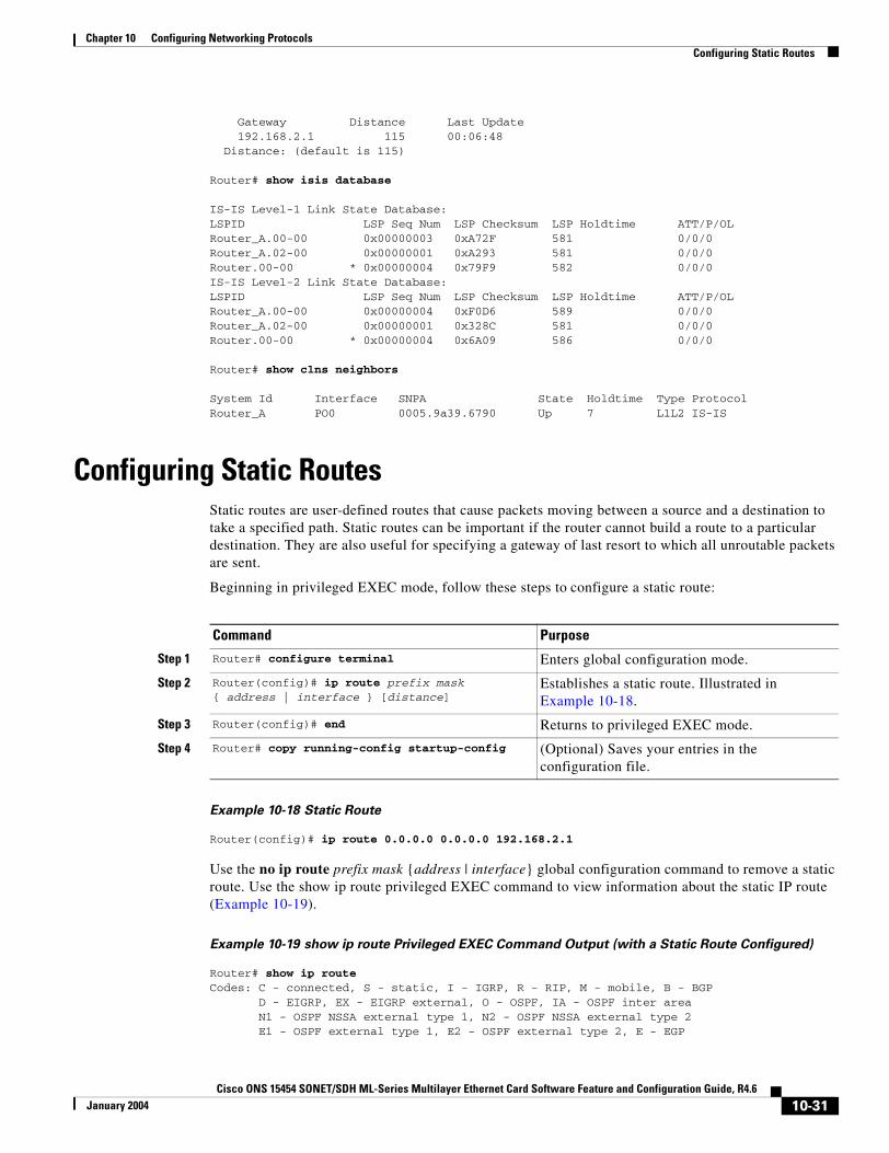
Chapter 10 Configuring Networking ProtocolsConfiguring Static Routes
Gateway Distance Last Update 192.168.2.1 115 00:06:48 Distance: (default is 115)
Router# show isis database
IS-IS Level-1 Link State Database:LSPID LSP Seq Num LSP Checksum LSP Holdtime ATT/P/OLRouter_A.00-00 0x00000003 0xA72F 581 0/0/0Router_A.02-00 0x00000001 0xA293 581 0/0/0Router.00-00 * 0x00000004 0x79F9 582 0/0/0IS-IS Level-2 Link State Database:LSPID LSP Seq Num LSP Checksum LSP Holdtime ATT/P/OLRouter_A.00-00 0x00000004 0xF0D6 589 0/0/0Router_A.02-00 0x00000001 0x328C 581 0/0/0Router.00-00 * 0x00000004 0x6A09 586 0/0/0
Router# show clns neighbors
System Id Interface SNPA State Holdtime Type ProtocolRouter_A PO0 0005.9a39.6790 Up 7 L1L2 IS-IS
Configuring Static RoutesStatic routes are user-defined routes that cause packets moving between a source and a destination to take a specified path. Static routes can be important if the router cannot build a route to a particular destination. They are also useful for specifying a gateway of last resort to which all unroutable packets are sent.
Beginning in privileged EXEC mode, follow these steps to configure a static route:
Example 10-18 Static Route
Router(config)# ip route 0.0.0.0 0.0.0.0 192.168.2.1
Use the no ip route prefix mask {address | interface} global configuration command to remove a static route. Use the show ip route privileged EXEC command to view information about the static IP route (Example 10-19).
Example 10-19 show ip route Privileged EXEC Command Output (with a Static Route Configured)
Router# show ip routeCodes: C - connected, S - static, I - IGRP, R - RIP, M - mobile, B - BGP D - EIGRP, EX - EIGRP external, O - OSPF, IA - OSPF inter area N1 - OSPF NSSA external type 1, N2 - OSPF NSSA external type 2 E1 - OSPF external type 1, E2 - OSPF external type 2, E - EGP
Command Purpose
Step 1 Router# configure terminal Enters global configuration mode.
Step 2 Router(config)# ip route prefix mask { address | interface } [distance]
Establishes a static route. Illustrated in Example 10-18.
Step 3 Router(config)# end Returns to privileged EXEC mode.
Step 4 Router# copy running-config startup-config (Optional) Saves your entries in the configuration file.
10-31Cisco ONS 15454 SONET/SDH ML-Series Multilayer Ethernet Card Software Feature and Configuration Guide, R4.6
January 2004
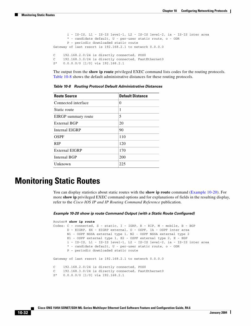
Chapter 10 Configuring Networking ProtocolsMonitoring Static Routes
i - IS-IS, L1 - IS-IS level-1, L2 - IS-IS level-2, ia - IS-IS inter area * - candidate default, U - per-user static route, o - ODR P - periodic downloaded static routeGateway of last resort is 192.168.2.1 to network 0.0.0.0
C 192.168.2.0/24 is directly connected, POS0C 192.168.3.0/24 is directly connected, FastEthernet0S* 0.0.0.0/0 [1/0] via 192.168.2.1
The output from the show ip route privileged EXEC command lists codes for the routing protocols. Table 10-8 shows the default administrative distances for these routing protocols.
Monitoring Static RoutesYou can display statistics about static routes with the show ip route command (Example 10-20). For more show ip privileged EXEC command options and for explanations of fields in the resulting display, refer to the Cisco IOS IP and IP Routing Command Reference publication.
Example 10-20 show ip route Command Output (with a Static Route Configured)
Router# show ip routeCodes: C - connected, S - static, I - IGRP, R - RIP, M - mobile, B - BGP D - EIGRP, EX - EIGRP external, O - OSPF, IA - OSPF inter area N1 - OSPF NSSA external type 1, N2 - OSPF NSSA external type 2 E1 - OSPF external type 1, E2 - OSPF external type 2, E - EGP i - IS-IS, L1 - IS-IS level-1, L2 - IS-IS level-2, ia - IS-IS inter area * - candidate default, U - per-user static route, o - ODR P - periodic downloaded static route
Gateway of last resort is 192.168.2.1 to network 0.0.0.0
C 192.168.2.0/24 is directly connected, POS0C 192.168.3.0/24 is directly connected, FastEthernet0S* 0.0.0.0/0 [1/0] via 192.168.2.1
Table 10-8 Routing Protocol Default Administrative Distances
Route Source Default Distance
Connected interface 0
Static route 1
EIRGP summary route 5
External BGP 20
Internal EIGRP 90
OSPF 110
RIP 120
External EIGRP 170
Internal BGP 200
Unknown 225
10-32Cisco ONS 15454 SONET/SDH ML-Series Multilayer Ethernet Card Software Feature and Configuration Guide, R4.6
January 2004
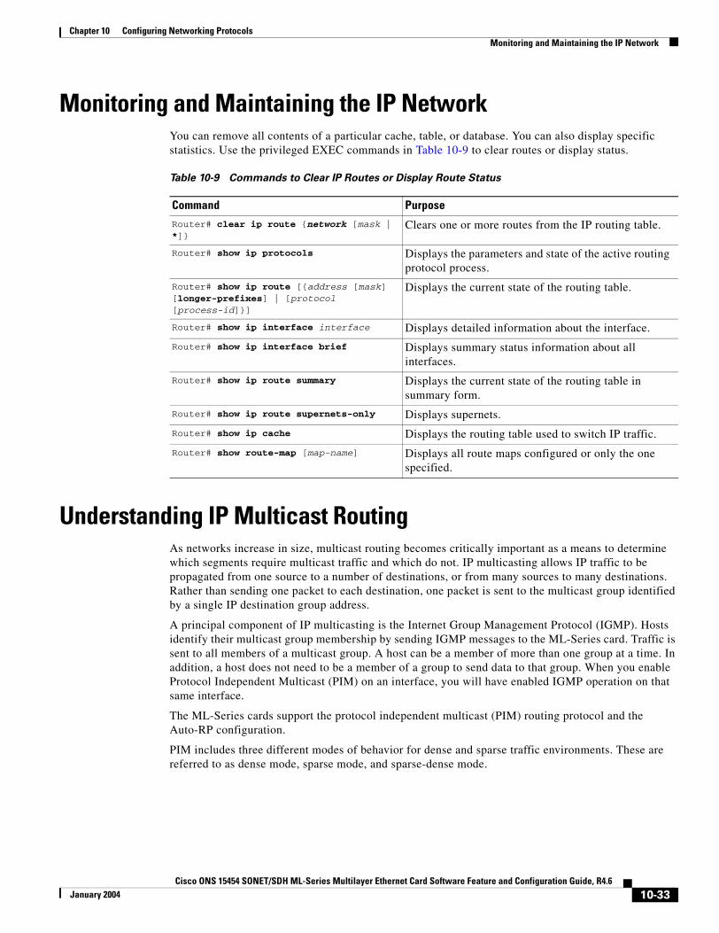
Chapter 10 Configuring Networking ProtocolsMonitoring and Maintaining the IP Network
Monitoring and Maintaining the IP NetworkYou can remove all contents of a particular cache, table, or database. You can also display specific statistics. Use the privileged EXEC commands in Table 10-9 to clear routes or display status.
Understanding IP Multicast RoutingAs networks increase in size, multicast routing becomes critically important as a means to determine which segments require multicast traffic and which do not. IP multicasting allows IP traffic to be propagated from one source to a number of destinations, or from many sources to many destinations. Rather than sending one packet to each destination, one packet is sent to the multicast group identified by a single IP destination group address.
A principal component of IP multicasting is the Internet Group Management Protocol (IGMP). Hosts identify their multicast group membership by sending IGMP messages to the ML-Series card. Traffic is sent to all members of a multicast group. A host can be a member of more than one group at a time. In addition, a host does not need to be a member of a group to send data to that group. When you enable Protocol Independent Multicast (PIM) on an interface, you will have enabled IGMP operation on that same interface.
The ML-Series cards support the protocol independent multicast (PIM) routing protocol and the Auto-RP configuration.
PIM includes three different modes of behavior for dense and sparse traffic environments. These are referred to as dense mode, sparse mode, and sparse-dense mode.
Table 10-9 Commands to Clear IP Routes or Display Route Status
Command Purpose
Router# clear ip route {network [mask | *]}
Clears one or more routes from the IP routing table.
Router# show ip protocols Displays the parameters and state of the active routing protocol process.
Router# show ip route [{address [mask] [longer-prefixes] | [protocol [process-id]}]
Displays the current state of the routing table.
Router# show ip interface interface Displays detailed information about the interface.
Router# show ip interface brief Displays summary status information about all interfaces.
Router# show ip route summary Displays the current state of the routing table in summary form.
Router# show ip route supernets-only Displays supernets.
Router# show ip cache Displays the routing table used to switch IP traffic.
Router# show route-map [map-name] Displays all route maps configured or only the one specified.
10-33Cisco ONS 15454 SONET/SDH ML-Series Multilayer Ethernet Card Software Feature and Configuration Guide, R4.6
January 2004
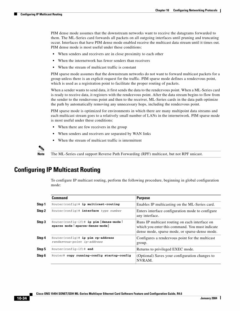
Chapter 10 Configuring Networking ProtocolsConfiguring IP Multicast Routing
PIM dense mode assumes that the downstream networks want to receive the datagrams forwarded to them. The ML-Series card forwards all packets on all outgoing interfaces until pruning and truncating occur. Interfaces that have PIM dense mode enabled receive the multicast data stream until it times out. PIM dense mode is most useful under these conditions:
• When senders and receivers are in close proximity to each other
• When the internetwork has fewer senders than receivers
• When the stream of multicast traffic is constant
PIM sparse mode assumes that the downstream networks do not want to forward multicast packets for a group unless there is an explicit request for the traffic. PIM sparse mode defines a rendezvous point, which is used as a registration point to facilitate the proper routing of packets.
When a sender wants to send data, it first sends the data to the rendezvous point. When a ML-Series card is ready to receive data, it registers with the rendezvous point. After the data stream begins to flow from the sender to the rendezvous point and then to the receiver, ML-Series cards in the data path optimize the path by automatically removing any unnecessary hops, including the rendezvous point.
PIM sparse mode is optimized for environments in which there are many multipoint data streams and each multicast stream goes to a relatively small number of LANs in the internetwork. PIM sparse mode is most useful under these conditions:
• When there are few receivers in the group
• When senders and receivers are separated by WAN links
• When the stream of multicast traffic is intermittent
Note The ML-Series card support Reverse Path Forwarding (RPF) multicast, but not RPF unicast.
Configuring IP Multicast RoutingTo configure IP multicast routing, perform the following procedure, beginning in global configuration mode:
Command Purpose
Step 1 Router(config)# ip multicast-routing Enables IP multicasting on the ML-Series card.
Step 2 Router(config)# interface type number Enters interface configuration mode to configure any interface.
Step 3 Router(config-if)# ip pim {dense-mode | sparse mode | sparse-dense-mode}
Runs IP multicast routing on each interface on which you enter this command. You must indicate dense mode, sparse mode, or sparse-dense mode.
Step 4 Router(config)# ip pim rp-address rendezvous-point ip-address
Configures a rendezvous point for the multicast group.
Step 5 Router(config-if)# end Returns to privileged EXEC mode.
Step 6 Router# copy running-config startup-config (Optional) Saves your configuration changes to NVRAM.
10-34Cisco ONS 15454 SONET/SDH ML-Series Multilayer Ethernet Card Software Feature and Configuration Guide, R4.6
January 2004
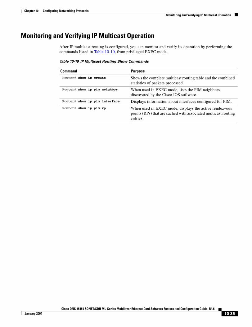
Chapter 10 Configuring Networking ProtocolsMonitoring and Verifying IP Multicast Operation
Monitoring and Verifying IP Multicast OperationAfter IP multicast routing is configured, you can monitor and verify its operation by performing the commands listed in Table 10-10, from privileged EXEC mode.
Table 10-10 IP Multicast Routing Show Commands
Command Purpose Router# show ip mroute Shows the complete multicast routing table and the combined
statistics of packets processed.
Router# show ip pim neighbor When used in EXEC mode, lists the PIM neighbors discovered by the Cisco IOS software.
Router# show ip pim interface Displays information about interfaces configured for PIM.
Router# show ip pim rp When used in EXEC mode, displays the active rendezvous points (RPs) that are cached with associated multicast routing entries.
10-35Cisco ONS 15454 SONET/SDH ML-Series Multilayer Ethernet Card Software Feature and Configuration Guide, R4.6
January 2004

Chapter 10 Configuring Networking ProtocolsMonitoring and Verifying IP Multicast Operation
10-36Cisco ONS 15454 SONET/SDH ML-Series Multilayer Ethernet Card Software Feature and Configuration Guide, R4.6
January 2004
Cisco ONS 15454 SONET/SDH ML-Series Multilayer Ethernet Card Softwar78-15224-02
C H A P T E R 11
Configuring IRBThis chapter describes how to configure integrated routing and bridging (IRB) for the ML-Series card. For more information about the Cisco IOS commands used in this chapter, refer to the Cisco IOS Command Reference publication.
This chapter includes the following major sections:
• Integrated Routing and Bridging, page 11-1
• Configuring IRB, page 11-2
• Monitoring and Verifying IRB, page 11-4
Caution Cisco Inter-Switch Link (ISL) and Cisco Dynamic Trunking Protocol (DTP) are not supported by the ML-Series, but the ML-Series broadcast forwards these formats. Using ISL or DTP on connecting devices is not recommended. Some Cisco devices attempt to use ISL or DTP by default.
Integrated Routing and BridgingYour network might require you to bridge local traffic within several segments and have hosts on the bridged segments reach the hosts or ML-Series card on routed networks. For example, if you are migrating bridged topologies into routed topologies, you might want to start by connecting some of the bridged segments to the routed networks.
Using the integrated routing and bridging (IRB) feature, you can route a given protocol between routed interfaces and bridge groups within a single ML-Series card. Specifically, local or unroutable traffic is bridged among the bridged interfaces in the same bridge group, while routable traffic is routed to other routed interfaces or bridge groups.
Because bridging is in the data link layer and routing is in the network layer, they have different protocol configuration models. With IP, for example, bridge group interfaces belong to the same network and have a collective IP network address. In contrast, each routed interface represents a distinct network and has its own IP network address. Integrated routing and bridging uses the concept of a Bridge Group Virtual Interface (BVI) to enable these interfaces to exchange packets for a given protocol.
A BVI is a virtual interface within the ML-Series card that acts like a normal routed interface. A BVI does not support bridging but actually represents the corresponding bridge group to routed interfaces within the ML-Series card. The interface number is the link between the BVI and the bridge group.
Before configuring IRB, consider the following:
• The default routing/bridging behavior in a bridge group (when IRB is enabled) is to bridge all packets. Make sure that you explicitly configure routing on the BVI for IP traffic.
11-1e Feature and Configuration Guide, R4.0
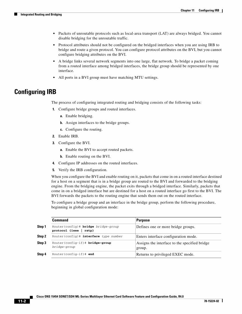
Chapter 11 Configuring IRBIntegrated Routing and Bridging
• Packets of unroutable protocols such as local-area transport (LAT) are always bridged. You cannot disable bridging for the unroutable traffic.
• Protocol attributes should not be configured on the bridged interfaces when you are using IRB to bridge and route a given protocol. You can configure protocol attributes on the BVI, but you cannot configure bridging attributes on the BVI.
• A bridge links several network segments into one large, flat network. To bridge a packet coming from a routed interface among bridged interfaces, the bridge group should be represented by one interface.
• All ports in a BVI group must have matching MTU settings.
Configuring IRBThe process of configuring integrated routing and bridging consists of the following tasks:
1. Configure bridge groups and routed interfaces.
a. Enable bridging.
b. Assign interfaces to the bridge groups.
c. Configure the routing.
2. Enable IRB.
3. Configure the BVI.
a. Enable the BVI to accept routed packets.
b. Enable routing on the BVI.
4. Configure IP addresses on the routed interfaces.
5. Verify the IRB configuration.
When you configure the BVI and enable routing on it, packets that come in on a routed interface destined for a host on a segment that is in a bridge group are routed to the BVI and forwarded to the bridging engine. From the bridging engine, the packet exits through a bridged interface. Similarly, packets that come in on a bridged interface but are destined for a host on a routed interface go first to the BVI. The BVI forwards the packets to the routing engine that sends them out on the routed interface.
To configure a bridge group and an interface in the bridge group, perform the following procedure, beginning in global configuration mode:
Command Purpose
Step 1 Router(config)# bridge bridge-group protocol {ieee | rstp}
Defines one or more bridge groups.
Step 2 Router(config)# interface type number Enters interface configuration mode.
Step 3 Router(config-if)# bridge-group bridge-group
Assigns the interface to the specified bridge group.
Step 4 Router(config-if)# end Returns to privileged EXEC mode.
11-2Cisco ONS 15454 SONET/SDH ML-Series Multilayer Ethernet Card Software Feature and Configuration Guide, R4.0
78-15224-02

Chapter 11 Configuring IRBIntegrated Routing and Bridging
To enable and configure IRB and BVI, perform the following procedure, beginning in global configuration mode:
Configuring IRB ExampleFigure 11-1 shows an example of an IRB configuration.
Figure 11-1 IRB Example
Configuring Router A
bridge irbbridge 1 protocol ieee bridge 1 route ip!!interface FastEthernet0 ip address 192.168.2.1 255.255.255.0!
Command Purpose
Step 1 Router(config)# bridge irb Enables IRB. Allows bridging of traffic.
Step 2 Router(config)# interface bvi bridge-group Configures the BVI by assigning the number of the corresponding bridge group to the BVI. Each bridge group can have only one corresponding BVI.
Step 3 Router(config-if)# ip address ip-address ip-address-subnet-mask
Configures IP addresses on routed interfaces.
Step 4 Router(config-if)# exit Exits the interface configuration mode.
Step 5 Router(config)# bridge bridge-group route protocol
Enables a BVI to accept and route routable packets received from its corresponding bridge group.
Enter this command for each protocol that you want the BVI to route from its corresponding bridge group to other routed interfaces.
Step 6 Router(config)# end Returns to the privileged EXEC mode.
Step 7 Router# copy running-config startup-config (Optional) Saves your configuration changes to NVRAM.
ONS 15454with ML100T-12
ONS 15454with ML100T-12
fast ethernet 0
pos 0pos 0
fast ethernet 0
Router_A Router_B
SONET/SDH
192.168.2.1/24 192.168.3.1/24
pos 1 pos 1
bridge 1
bridge 1
bridge 1
bridge 1
BVI 1 192.168.1.1/24 BVI 1 192.168.1.2/24
8344
6
11-3Cisco ONS 15454 SONET/SDH ML-Series Multilayer Ethernet Card Software Feature and Configuration Guide, R4.0
78-15224-02
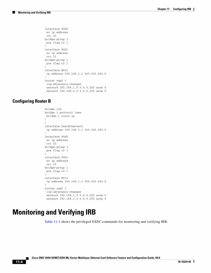
Chapter 11 Configuring IRBMonitoring and Verifying IRB
interface POS0 no ip address crc 32bridge-group 1 pos flag c2 1!interface POS1 no ip address crc 32bridge-group 1 pos flag c2 1!interface BVI1 ip address 192.168.1.1 255.255.255.0!router ospf 1 log-adjacency-changes network 192.168.1.0 0.0.0.255 area 0 network 192.168.2.0 0.0.0.255 area 0
Configuring Router B
bridge irbbridge 1 protocol ieee bridge 1 route ip!!interface FastEthernet0 ip address 192.168.3.1 255.255.255.0!interface POS0 no ip address crc 32bridge-group 1 pos flag c2 1!interface POS1 no ip address crc 32bridge-group 1 pos flag c2 1!interface BVI1 ip address 192.168.1.2 255.255.255.0!router ospf 1 log-adjacency-changes network 192.168.1.0 0.0.0.255 area 0 network 192.168.3.0 0.0.0.255 area 0
Monitoring and Verifying IRBTable 11-1 shows the privileged EXEC commands for monitoring and verifying IRB.
11-4Cisco ONS 15454 SONET/SDH ML-Series Multilayer Ethernet Card Software Feature and Configuration Guide, R4.0
78-15224-02
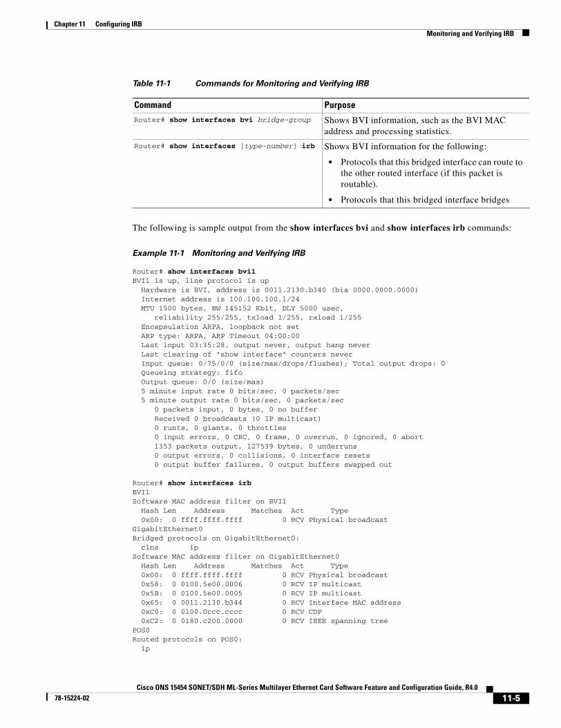
Chapter 11 Configuring IRBMonitoring and Verifying IRB
The following is sample output from the show interfaces bvi and show interfaces irb commands:
Example 11-1 Monitoring and Verifying IRB
Router# show interfaces bvi1BVI1 is up, line protocol is up Hardware is BVI, address is 0011.2130.b340 (bia 0000.0000.0000) Internet address is 100.100.100.1/24 MTU 1500 bytes, BW 145152 Kbit, DLY 5000 usec, reliability 255/255, txload 1/255, rxload 1/255 Encapsulation ARPA, loopback not set ARP type: ARPA, ARP Timeout 04:00:00 Last input 03:35:28, output never, output hang never Last clearing of "show interface" counters never Input queue: 0/75/0/0 (size/max/drops/flushes); Total output drops: 0 Queueing strategy: fifo Output queue: 0/0 (size/max) 5 minute input rate 0 bits/sec, 0 packets/sec 5 minute output rate 0 bits/sec, 0 packets/sec 0 packets input, 0 bytes, 0 no buffer Received 0 broadcasts (0 IP multicast) 0 runts, 0 giants, 0 throttles 0 input errors, 0 CRC, 0 frame, 0 overrun, 0 ignored, 0 abort 1353 packets output, 127539 bytes, 0 underruns 0 output errors, 0 collisions, 0 interface resets 0 output buffer failures, 0 output buffers swapped out
Router# show interfaces irbBVI1Software MAC address filter on BVI1 Hash Len Address Matches Act Type 0x00: 0 ffff.ffff.ffff 0 RCV Physical broadcastGigabitEthernet0Bridged protocols on GigabitEthernet0: clns ipSoftware MAC address filter on GigabitEthernet0 Hash Len Address Matches Act Type 0x00: 0 ffff.ffff.ffff 0 RCV Physical broadcast 0x58: 0 0100.5e00.0006 0 RCV IP multicast 0x5B: 0 0100.5e00.0005 0 RCV IP multicast 0x65: 0 0011.2130.b344 0 RCV Interface MAC address 0xC0: 0 0100.0ccc.cccc 0 RCV CDP 0xC2: 0 0180.c200.0000 0 RCV IEEE spanning treePOS0Routed protocols on POS0: ip
Table 11-1 Commands for Monitoring and Verifying IRB
Command Purpose
Router# show interfaces bvi bridge-group Shows BVI information, such as the BVI MAC address and processing statistics.
Router# show interfaces [type-number] irb Shows BVI information for the following:
• Protocols that this bridged interface can route to the other routed interface (if this packet is routable).
• Protocols that this bridged interface bridges
11-5Cisco ONS 15454 SONET/SDH ML-Series Multilayer Ethernet Card Software Feature and Configuration Guide, R4.0
78-15224-02

Chapter 11 Configuring IRBMonitoring and Verifying IRB
Bridged protocols on POS0: clns ipSoftware MAC address filter on POS0 Hash Len Address Matches Act Type 0x00: 0 ffff.ffff.ffff 9 RCV Physical broadcast 0x58: 0 0100.5e00.0006 0 RCV IP multicast 0x5B: 0 0100.5e00.0005 1313 RCV IP multicast 0x61: 0 0011.2130.b340 38 RCV Interface MAC address 0x61: 1 0011.2130.b340 0 RCV Bridge-group Virtual Interface 0x65: 0 0011.2130.b344 0 RCV Interface MAC address 0xC0: 0 0100.0ccc.cccc 224 RCV CDP 0xC2: 0 0180.c200.0000 0 RCV IEEE spanning treePOS1SPR1Bridged protocols on SPR1: clns ipSoftware MAC address filter on SPR1 Hash Len Address Matches Act Type 0x00: 0 ffff.ffff.ffff 0 RCV Physical broadcast 0x60: 0 0011.2130.b341 0 RCV Interface MAC address 0x65: 0 0011.2130.b344 0 RCV Interface MAC address 0xC0: 0 0100.0ccc.cccc 0 RCV CDP 0xC2: 0 0180.c200.0000 0 RCV IEEE spanning tree
Table 11-1 describes significant fields shown in the display.
Table 11-2 show interfaces irb Field Descriptions
Field Description
Routed protocols on… List of the routed protocols configured for the speci-
fied interface.
Bridged protocols on… List of the bridged protocols configured for the speci-
fied interface.
Software MAC address filter on… Table of software MAC address filter information for
the specified interface.
Hash Hash key/relative position in the keyed list for this
MAC-address entry.
Len Length of this entry to the beginning element of this
hash chain.
Address Canonical (Ethernet ordered) MAC address.
Matches Number of received packets matched to this MAC
address.
Routed protocols on… List of the routed protocols configured for the speci-
fied interface.
Bridged protocols on… List of the bridged protocols configured for the speci-
fied interface.
11-6Cisco ONS 15454 SONET/SDH ML-Series Multilayer Ethernet Card Software Feature and Configuration Guide, R4.0
78-15224-02
Cisco ONS 15454 SONET/SDH ML-Series Multilayer Ethernet Card SoftwarJanuary 2004
C H A P T E R 12
Configuring VRF LiteThis chapter describes how to configure VPN Routing and Forwarding Lite (VRF Lite) for the ML-Series cards. For additional information about the Cisco IOS commands used in this chapter, refer to the Cisco IOS Command Reference publication. This chapter contains the following major sections:
• Understanding VRF Lite, page 12-1
• Configuring VRF Lite, page 12-2
• VRF Lite Configuration Example, page 12-2
• Monitoring and Verifying VRF Lite, page 12-7
Note If you have already configured bridging, you may now proceed with configuring VRF Lite as an optional step.
Understanding VRF LiteVRF is an extension of IP routing that provides multiple routing instances. It provides a separate IP routing and forwarding table to each VPN and is used in concert with MP-iBGP (Multi-Protocol internal BGP) between provider equipment (PE) routers to provide Layer 3 MPLS-VPN. However, ML-Series VRF implementation is without MP-iBGP. With VRF Lite, the ML Series is considered a PE-extension or a customer equipment (CE)-extension. VRF Lite is considered a PE-extension since its has VRF (but without MP-iBGP), and it is considered a CE-extension since this CE can have multiple VRFs and serves many customer with one CE box.
Under VRF Lite, an ML-Series CE can have multiple interfaces/subinterfaces with PE for different customers (while a normal CE is only for one customer). It holds VRFs (routing information) locally and it does not distribute the VRFs to its connected PE. It uses VRF information to direct traffic to the correct interfaces/subinterfaces when it receives traffic from customers’ routers or from Internet service provider (ISP) PE router(s).
12-1e Feature and Configuration Guide, R4.6
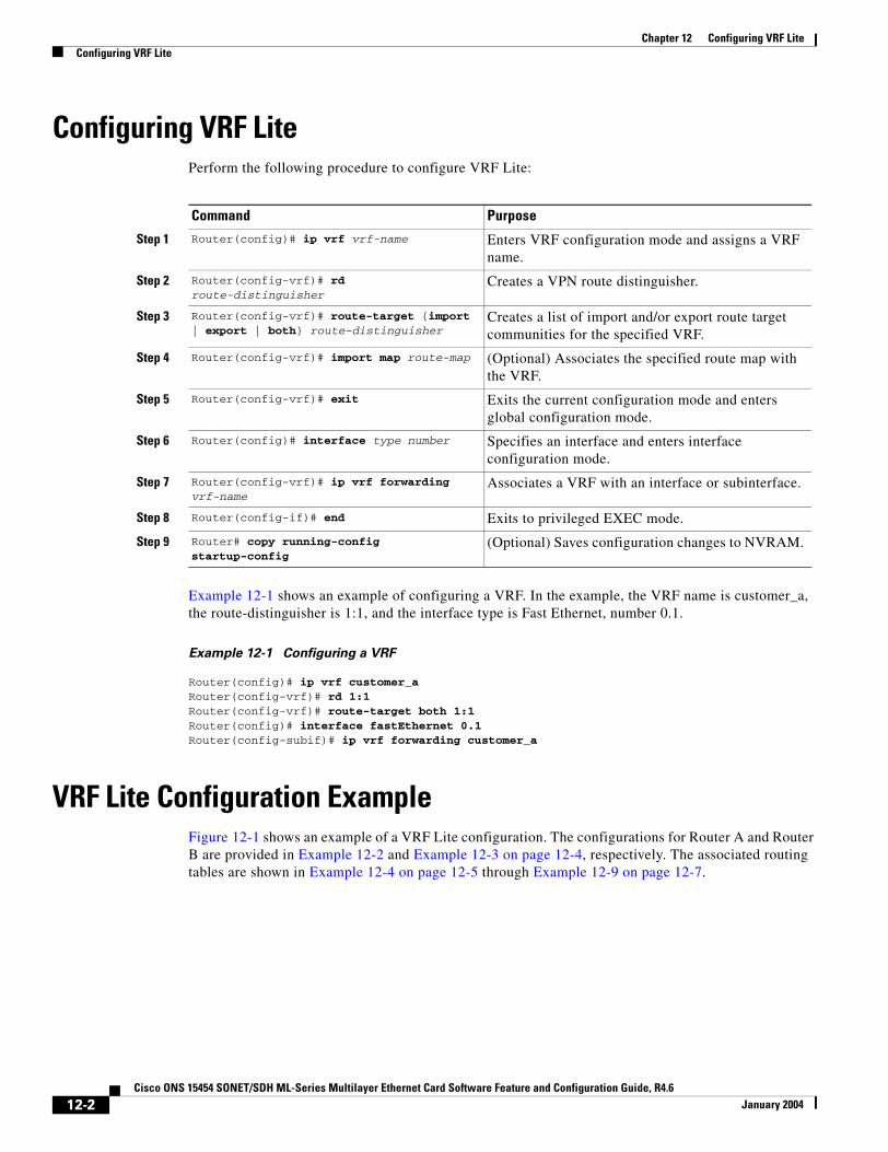
Chapter 12 Configuring VRF LiteConfiguring VRF Lite
Configuring VRF LitePerform the following procedure to configure VRF Lite:
Example 12-1 shows an example of configuring a VRF. In the example, the VRF name is customer_a, the route-distinguisher is 1:1, and the interface type is Fast Ethernet, number 0.1.
Example 12-1 Configuring a VRF
Router(config)# ip vrf customer_aRouter(config-vrf)# rd 1:1Router(config-vrf)# route-target both 1:1Router(config)# interface fastEthernet 0.1Router(config-subif)# ip vrf forwarding customer_a
VRF Lite Configuration ExampleFigure 12-1 shows an example of a VRF Lite configuration. The configurations for Router A and Router B are provided in Example 12-2 and Example 12-3 on page 12-4, respectively. The associated routing tables are shown in Example 12-4 on page 12-5 through Example 12-9 on page 12-7.
Command Purpose
Step 1 Router(config)# ip vrf vrf-name Enters VRF configuration mode and assigns a VRF name.
Step 2 Router(config-vrf)# rd route-distinguisher
Creates a VPN route distinguisher.
Step 3 Router(config-vrf)# route-target {import | export | both} route-distinguisher
Creates a list of import and/or export route target communities for the specified VRF.
Step 4 Router(config-vrf)# import map route-map (Optional) Associates the specified route map with the VRF.
Step 5 Router(config-vrf)# exit Exits the current configuration mode and enters global configuration mode.
Step 6 Router(config)# interface type number Specifies an interface and enters interface configuration mode.
Step 7 Router(config-vrf)# ip vrf forwarding vrf-name
Associates a VRF with an interface or subinterface.
Step 8 Router(config-if)# end Exits to privileged EXEC mode.
Step 9 Router# copy running-config startup-config
(Optional) Saves configuration changes to NVRAM.
12-2Cisco ONS 15454 SONET/SDH ML-Series Multilayer Ethernet Card Software Feature and Configuration Guide, R4.6
January 2004
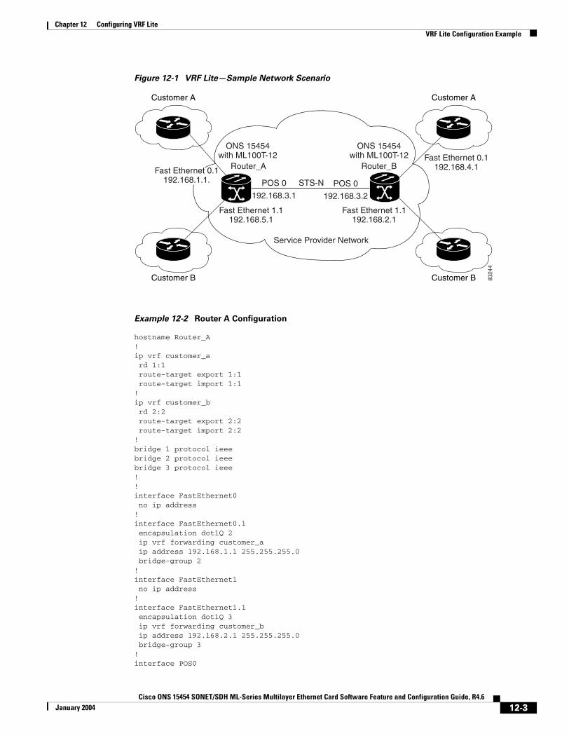
Chapter 12 Configuring VRF LiteVRF Lite Configuration Example
Figure 12-1 VRF Lite—Sample Network Scenario
Example 12-2 Router A Configuration
hostname Router_A!ip vrf customer_a rd 1:1 route-target export 1:1 route-target import 1:1!ip vrf customer_b rd 2:2 route-target export 2:2 route-target import 2:2!bridge 1 protocol ieeebridge 2 protocol ieeebridge 3 protocol ieee!!interface FastEthernet0 no ip address!interface FastEthernet0.1 encapsulation dot1Q 2 ip vrf forwarding customer_a ip address 192.168.1.1 255.255.255.0 bridge-group 2!interface FastEthernet1 no ip address!interface FastEthernet1.1 encapsulation dot1Q 3 ip vrf forwarding customer_b ip address 192.168.2.1 255.255.255.0 bridge-group 3!interface POS0
Customer A
Customer BCustomer B
Customer A
ONS 15454with ML100T-12
POS 0POS 0
192.168.3.2192.168.3.1
Router_A
ONS 15454with ML100T-12
Router_B
Fast Ethernet 1.1192.168.5.1
Fast Ethernet 0.1192.168.1.1.
Fast Ethernet 0.1192.168.4.1
Fast Ethernet 1.1192.168.2.1
Service Provider Network
STS-N
8324
4
12-3Cisco ONS 15454 SONET/SDH ML-Series Multilayer Ethernet Card Software Feature and Configuration Guide, R4.6
January 2004
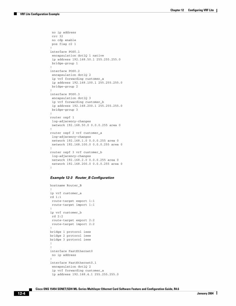
Chapter 12 Configuring VRF LiteVRF Lite Configuration Example
no ip address crc 32 no cdp enable pos flag c2 1!interface POS0.1 encapsulation dot1Q 1 native ip address 192.168.50.1 255.255.255.0 bridge-group 1!interface POS0.2 encapsulation dot1Q 2 ip vrf forwarding customer_a ip address 192.168.100.1 255.255.255.0 bridge-group 2!interface POS0.3 encapsulation dot1Q 3 ip vrf forwarding customer_b ip address 192.168.200.1 255.255.255.0 bridge-group 3!router ospf 1 log-adjacency-changes network 192.168.50.0 0.0.0.255 area 0!router ospf 2 vrf customer_a log-adjacency-changes network 192.168.1.0 0.0.0.255 area 0 network 192.168.100.0 0.0.0.255 area 0!router ospf 3 vrf customer_b log-adjacency-changes network 192.168.2.0 0.0.0.255 area 0 network 192.168.200.0 0.0.0.255 area 0!
Example 12-3 Router_B Configuration
hostname Router_B!ip vrf customer_a rd 1:1 route-target export 1:1 route-target import 1:1!ip vrf customer_b rd 2:2 route-target export 2:2 route-target import 2:2!bridge 1 protocol ieeebridge 2 protocol ieeebridge 3 protocol ieee!!interface FastEthernet0 no ip address!interface FastEthernet0.1 encapsulation dot1Q 2 ip vrf forwarding customer_a ip address 192.168.4.1 255.255.255.0
12-4Cisco ONS 15454 SONET/SDH ML-Series Multilayer Ethernet Card Software Feature and Configuration Guide, R4.6
January 2004
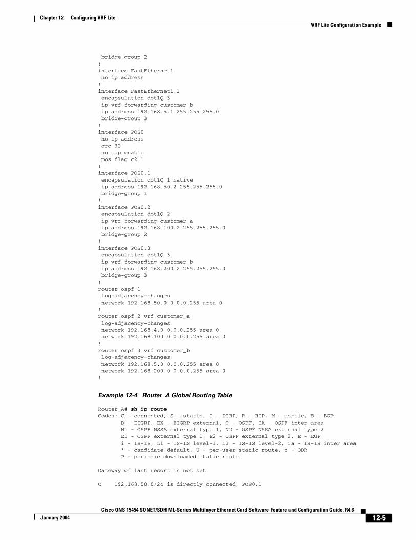
Chapter 12 Configuring VRF LiteVRF Lite Configuration Example
bridge-group 2!interface FastEthernet1 no ip address!interface FastEthernet1.1 encapsulation dot1Q 3 ip vrf forwarding customer_b ip address 192.168.5.1 255.255.255.0 bridge-group 3!interface POS0 no ip address crc 32 no cdp enable pos flag c2 1!interface POS0.1 encapsulation dot1Q 1 native ip address 192.168.50.2 255.255.255.0 bridge-group 1!interface POS0.2 encapsulation dot1Q 2 ip vrf forwarding customer_a ip address 192.168.100.2 255.255.255.0 bridge-group 2!interface POS0.3 encapsulation dot1Q 3 ip vrf forwarding customer_b ip address 192.168.200.2 255.255.255.0 bridge-group 3!router ospf 1 log-adjacency-changes network 192.168.50.0 0.0.0.255 area 0!router ospf 2 vrf customer_a log-adjacency-changes network 192.168.4.0 0.0.0.255 area 0 network 192.168.100.0 0.0.0.255 area 0!router ospf 3 vrf customer_b log-adjacency-changes network 192.168.5.0 0.0.0.255 area 0 network 192.168.200.0 0.0.0.255 area 0!
Example 12-4 Router_A Global Routing Table
Router_A# sh ip routeCodes: C - connected, S - static, I - IGRP, R - RIP, M - mobile, B - BGP D - EIGRP, EX - EIGRP external, O - OSPF, IA - OSPF inter area N1 - OSPF NSSA external type 1, N2 - OSPF NSSA external type 2 E1 - OSPF external type 1, E2 - OSPF external type 2, E - EGP i - IS-IS, L1 - IS-IS level-1, L2 - IS-IS level-2, ia - IS-IS inter area * - candidate default, U - per-user static route, o - ODR P - periodic downloaded static route
Gateway of last resort is not set
C 192.168.50.0/24 is directly connected, POS0.1
12-5Cisco ONS 15454 SONET/SDH ML-Series Multilayer Ethernet Card Software Feature and Configuration Guide, R4.6
January 2004
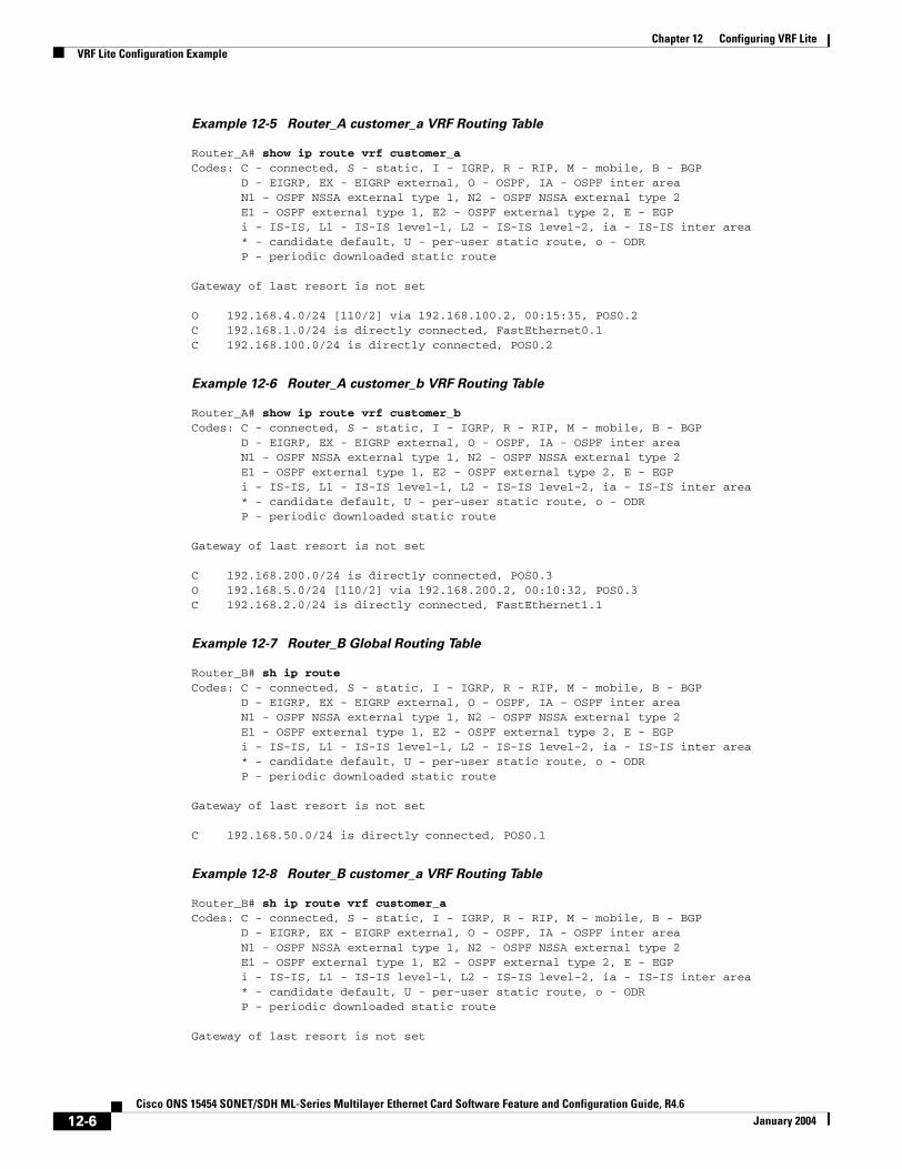
Chapter 12 Configuring VRF LiteVRF Lite Configuration Example
Example 12-5 Router_A customer_a VRF Routing Table
Router_A# show ip route vrf customer_aCodes: C - connected, S - static, I - IGRP, R - RIP, M - mobile, B - BGP D - EIGRP, EX - EIGRP external, O - OSPF, IA - OSPF inter area N1 - OSPF NSSA external type 1, N2 - OSPF NSSA external type 2 E1 - OSPF external type 1, E2 - OSPF external type 2, E - EGP i - IS-IS, L1 - IS-IS level-1, L2 - IS-IS level-2, ia - IS-IS inter area * - candidate default, U - per-user static route, o - ODR P - periodic downloaded static route
Gateway of last resort is not set
O 192.168.4.0/24 [110/2] via 192.168.100.2, 00:15:35, POS0.2C 192.168.1.0/24 is directly connected, FastEthernet0.1C 192.168.100.0/24 is directly connected, POS0.2
Example 12-6 Router_A customer_b VRF Routing Table
Router_A# show ip route vrf customer_bCodes: C - connected, S - static, I - IGRP, R - RIP, M - mobile, B - BGP D - EIGRP, EX - EIGRP external, O - OSPF, IA - OSPF inter area N1 - OSPF NSSA external type 1, N2 - OSPF NSSA external type 2 E1 - OSPF external type 1, E2 - OSPF external type 2, E - EGP i - IS-IS, L1 - IS-IS level-1, L2 - IS-IS level-2, ia - IS-IS inter area * - candidate default, U - per-user static route, o - ODR P - periodic downloaded static route
Gateway of last resort is not set
C 192.168.200.0/24 is directly connected, POS0.3O 192.168.5.0/24 [110/2] via 192.168.200.2, 00:10:32, POS0.3C 192.168.2.0/24 is directly connected, FastEthernet1.1
Example 12-7 Router_B Global Routing Table
Router_B# sh ip routeCodes: C - connected, S - static, I - IGRP, R - RIP, M - mobile, B - BGP D - EIGRP, EX - EIGRP external, O - OSPF, IA - OSPF inter area N1 - OSPF NSSA external type 1, N2 - OSPF NSSA external type 2 E1 - OSPF external type 1, E2 - OSPF external type 2, E - EGP i - IS-IS, L1 - IS-IS level-1, L2 - IS-IS level-2, ia - IS-IS inter area * - candidate default, U - per-user static route, o - ODR P - periodic downloaded static route
Gateway of last resort is not set
C 192.168.50.0/24 is directly connected, POS0.1
Example 12-8 Router_B customer_a VRF Routing Table
Router_B# sh ip route vrf customer_aCodes: C - connected, S - static, I - IGRP, R - RIP, M - mobile, B - BGP D - EIGRP, EX - EIGRP external, O - OSPF, IA - OSPF inter area N1 - OSPF NSSA external type 1, N2 - OSPF NSSA external type 2 E1 - OSPF external type 1, E2 - OSPF external type 2, E - EGP i - IS-IS, L1 - IS-IS level-1, L2 - IS-IS level-2, ia - IS-IS inter area * - candidate default, U - per-user static route, o - ODR P - periodic downloaded static route
Gateway of last resort is not set
12-6Cisco ONS 15454 SONET/SDH ML-Series Multilayer Ethernet Card Software Feature and Configuration Guide, R4.6
January 2004
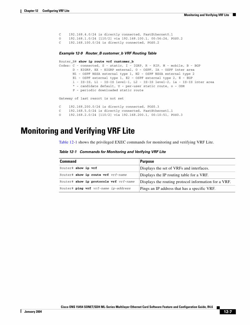
Chapter 12 Configuring VRF LiteMonitoring and Verifying VRF Lite
C 192.168.4.0/24 is directly connected, FastEthernet0.1O 192.168.1.0/24 [110/2] via 192.168.100.1, 00:56:24, POS0.2C 192.168.100.0/24 is directly connected, POS0.2
Example 12-9 Router_B customer_b VRF Routing Table
Router_B# show ip route vrf customer_bCodes: C - connected, S - static, I - IGRP, R - RIP, M - mobile, B - BGP D - EIGRP, EX - EIGRP external, O - OSPF, IA - OSPF inter area N1 - OSPF NSSA external type 1, N2 - OSPF NSSA external type 2 E1 - OSPF external type 1, E2 - OSPF external type 2, E - EGP i - IS-IS, L1 - IS-IS level-1, L2 - IS-IS level-2, ia - IS-IS inter area * - candidate default, U - per-user static route, o - ODR P - periodic downloaded static route
Gateway of last resort is not set
C 192.168.200.0/24 is directly connected, POS0.3C 192.168.5.0/24 is directly connected, FastEthernet1.1O 192.168.2.0/24 [110/2] via 192.168.200.1, 00:10:51, POS0.3
Monitoring and Verifying VRF Lite Table 12-1 shows the privileged EXEC commands for monitoring and verifying VRF Lite.
Table 12-1 Commands for Monitoring and Verifying VRF Lite
Command Purpose
Router# show ip vrf Displays the set of VRFs and interfaces.
Router# show ip route vrf vrf-name Displays the IP routing table for a VRF.
Router# show ip protocols vrf vrf-name Displays the routing protocol information for a VRF.
Router# ping vrf vrf-name ip-address Pings an IP address that has a specific VRF.
12-7Cisco ONS 15454 SONET/SDH ML-Series Multilayer Ethernet Card Software Feature and Configuration Guide, R4.6
January 2004

Chapter 12 Configuring VRF LiteMonitoring and Verifying VRF Lite
12-8Cisco ONS 15454 SONET/SDH ML-Series Multilayer Ethernet Card Software Feature and Configuration Guide, R4.6
January 2004

Cisco ONS 15454 SONET/SDH ML-Series Multilayer Ethernet Card SoftwarMarch 2005
C H A P T E R 13
Configuring Quality of ServiceThis chapter describes the Quality of Service (QoS) features built into your ML-Series card and how to map QoS scheduling at both the system and interface levels.
This chapter contains the following major sections:
• Understanding QoS, page 13-1
• ML-Series QoS, page 13-3
• QoS on RPR, page 13-10
• Configuring QoS, page 13-10
• Monitoring and Verifying QoS Configuration, page 13-16
• QoS Configuration Examples, page 13-17
• Understanding CoS-based Packet Statistics, page 13-22
• Configuring CoS-based Packet Statistics, page 13-23
The ML-Series card employs the Cisco IOS Modular QoS CLI (MQC). For more information about general MQC configuration, refer to the following Cisco IOS documents:
• Cisco IOS Quality of Service Solutions Configuration Guide, Release 12.1 at this URL: http://www.cisco.com/univercd/cc/td/doc/product/software/ios121/121cgcr/qos_c/index.htm
• Cisco IOS Quality of Service Solutions Command Reference, Release 12.1 at this URL: http://www.cisco.com/univercd/cc/td/doc/product/software/ios121/121cgcr/qos_r/index.htm
Understanding QoSThe ML-Series card multiplexes multiple IP/Ethernet services onto the SONET/SDH circuit and dynamically allocates transmission bandwidth to data services based on data service requirements, which allows the network to operate at a significantly higher level of utilization. To support service-level agreements (SLAs), this dynamic allocation must accommodate the service elements of bandwidth, including loss and delay. The characteristics of these service elements make up QoS.
13-1e Feature and Configuration Guide, R4.6
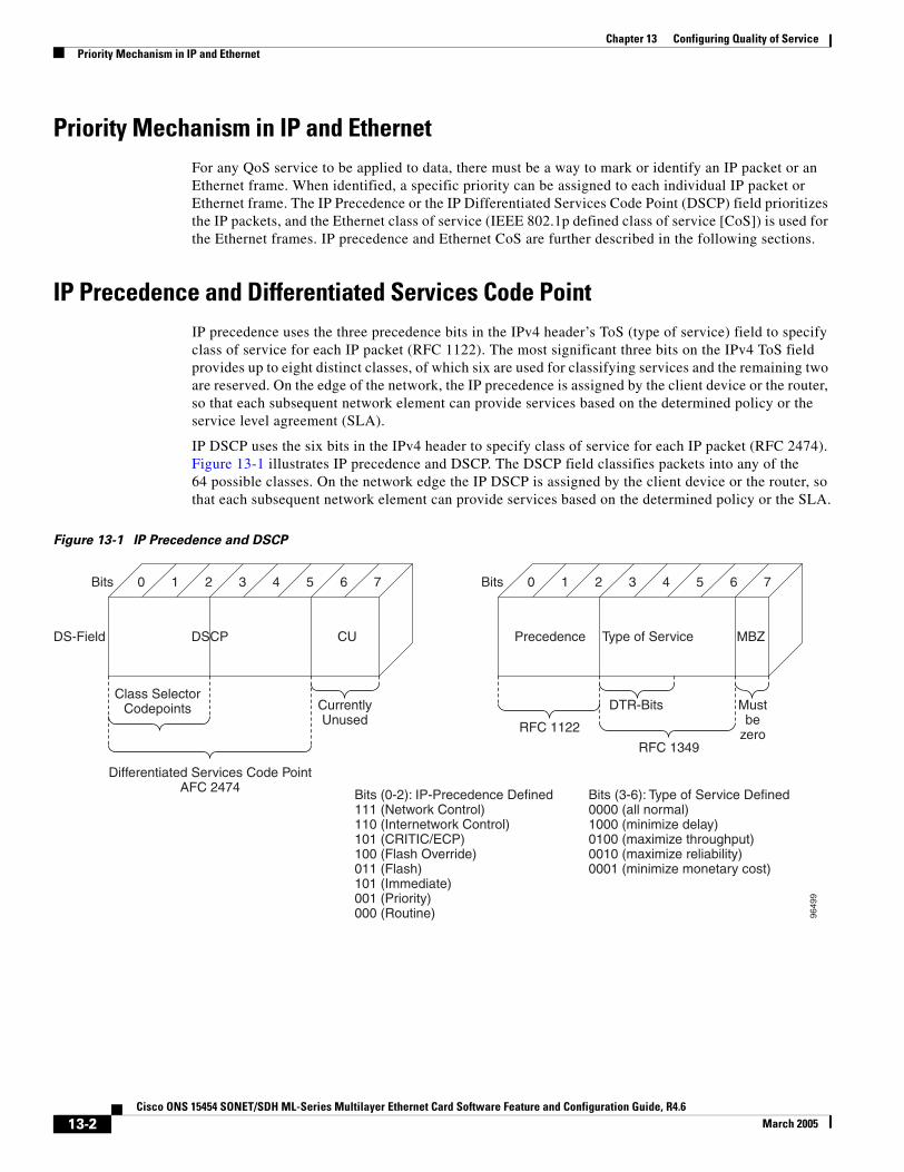
Chapter 13 Configuring Quality of ServicePriority Mechanism in IP and Ethernet
Priority Mechanism in IP and EthernetFor any QoS service to be applied to data, there must be a way to mark or identify an IP packet or an Ethernet frame. When identified, a specific priority can be assigned to each individual IP packet or Ethernet frame. The IP Precedence or the IP Differentiated Services Code Point (DSCP) field prioritizes the IP packets, and the Ethernet class of service (IEEE 802.1p defined class of service [CoS]) is used for the Ethernet frames. IP precedence and Ethernet CoS are further described in the following sections.
IP Precedence and Differentiated Services Code Point IP precedence uses the three precedence bits in the IPv4 header’s ToS (type of service) field to specify class of service for each IP packet (RFC 1122). The most significant three bits on the IPv4 ToS field provides up to eight distinct classes, of which six are used for classifying services and the remaining two are reserved. On the edge of the network, the IP precedence is assigned by the client device or the router, so that each subsequent network element can provide services based on the determined policy or the service level agreement (SLA).
IP DSCP uses the six bits in the IPv4 header to specify class of service for each IP packet (RFC 2474). Figure 13-1 illustrates IP precedence and DSCP. The DSCP field classifies packets into any of the 64 possible classes. On the network edge the IP DSCP is assigned by the client device or the router, so that each subsequent network element can provide services based on the determined policy or the SLA.
Figure 13-1 IP Precedence and DSCP
9649
9
DS-Field
Class SelectorCodepoints Currently
Unused
Differentiated Services Code PointAFC 2474
DSCP CU
0Bits 1 2 3 4 5 6 7
RFC 1122
RFC 1349
Mustbe
zero
DTR-Bits
Bits (0-2): IP-Precedence Defined111 (Network Control)110 (Internetwork Control)101 (CRITIC/ECP)100 (Flash Override)011 (Flash)101 (Immediate)001 (Priority)000 (Routine)
Bits (3-6): Type of Service Defined0000 (all normal)1000 (minimize delay)0100 (maximize throughput)0010 (maximize reliability)0001 (minimize monetary cost)
Precedence Type of Service MBZ
0Bits 1 2 3 4 5 6 7
13-2Cisco ONS 15454 SONET/SDH ML-Series Multilayer Ethernet Card Software Feature and Configuration Guide, R4.6
March 2005

Chapter 13 Configuring Quality of ServiceEthernet CoS
Ethernet CoSEthernet CoS refers to three bits within a four byte IEEE 802.1Q (VLAN) header used to indicate the priority of the Ethernet frame as it passes through a switched network. The CoS bits in the IEEE 802.1Q header are commonly referred to as the IEEE 802.1p bits. There are three CoS bits that provide eight classes, matching the number delivered by IP precedence. In many real-world networks, a packet might traverse both Layer 2 and Layer 3 domains. To maintain QoS across the network, the IP Type of Service (ToS) can be mapped to the Ethernet CoS and vice versa, for example in linear or one-to-one mapping, because each mechanism supports eight classes. Similarly, a set of DSCP values (64 classes) can be mapped into each of the eight individual Ethernet CoS values. Figure 13-2 is an IEEE 802.1Q Ethernet frame, which consists of a 2-byte Ethertype and a 2-byte tag (IEEE 802.1Q Tag) on the Ethernet protocol header.
Figure 13-2 Ethernet Frame and the CoS Bit (IEEE 802.1p)
ML-Series QoSThe ML-Series QoS classifies each packet in the network based on its input interface, bridge group (VLAN), Ethernet CoS, IP precedence, IP DSCP, or RPR-CoS. After they are classified into class flows, further QoS functions can be applied to each packet as it traverses the card. Figure 13-3 illustrates the ML-Series QoS flow.
Figure 13-3 ML-Series QoS Flow
Policing provided by the ML-Series card ensures that attached equipment does not submit more than a predefined amount of bandwidth (Rate Limiting) into the network. The policing feature can be used to enforce the committed information rate (CIR) and the peak information rate (PIR) available to a customer at an interface. Policing also helps characterize the statistical nature of the information allowed
9649
6
Destination Address6
Source Address6
Type=81002
Tag Control Information2
Type/Length2
MAC DATA
PAD42~
1500
FCS4
IEEE 802.1Q Tag
VLAN ID
CFICoS
IEEE 802.1p(3 bits)
9649
8
Policing & MarkingClassification
QoS Actions at Ingress QoS Actions at Egress
Queueing & ScheduleingClassification
13-3Cisco ONS 15454 SONET/SDH ML-Series Multilayer Ethernet Card Software Feature and Configuration Guide, R4.6
March 2005

Chapter 13 Configuring Quality of ServiceClassification
into the network so that traffic engineering can more effectively ensure that the amount of committed bandwidth is available on the network, and the peak bandwidth is over-subscribed with an appropriate ratio. The policing action is applied per classification.
Priority marking can set the Ethernet IEEE 802.1p CoS bits or RPR-CoS bits as they exit the ML-Series card. The marking feature operates on the outer IEEE 802.1p tag, and provides a mechanism for tagging packets at the ingress of a QinQ packet. The subsequent network elements can provide QoS based only on this service-provider-created QoS indicator.
Per-class flow queuing enables fair access to excess network bandwidth, allows allocation of bandwidth to support SLAs, and ensures that applications with high network resource requirements are adequately served. Buffers are allocated to queues dynamically from a shared resource pool. The allocation process incorporates the instantaneous system load as well as the allocated bandwidth to each queue to optimize buffer allocation. Congestion management on the ML-Series is performed through a tail drop mechanism along with discard eligibility on the egress scheduler.
The ML-Series uses a Weighted Deficit Round Robin (WDRR) scheduling process to provide fair access to excess bandwidth as well as guaranteed throughput to each class flow.
Admission control is a process that is invoked each time that service is configured on the ML-Series card to ensure that QoS resources are not overcommitted. In particular, admission control ensures that no configurations are accepted, where a sum of the committed bandwidths on an interface exceeds total bandwidth on the interface.
ClassificationClassification can be based on any single packet classification criteria or a combination (logical AND and OR). A total of 254 classes, not including the class default, can be defined on the card. Classification of packets is configured using the Modular CLI class-map command. For traffic transiting the resilient packet ring (RPR), only the input interface and/or the RPR-CoS can be used as classification criteria.
PolicingDual leaky bucket policer is a process where the first bucket (CIR bucket) is filled with tokens at a known rate (CIR), which is a parameter that can be configured by the operator. Figure 13-4 illustrates the dual leaky bucket policer model. The tokens fill the bucket up to a maximum level, which is the amount of burstable committed (BC) traffic on the policer. The nonconforming packets of the first bucket are the overflow packets, which are passed to the second leaky bucket (the PIR bucket). The second leaky bucket is filled with these tokens at a known rate (PIR), which is a parameter that can be configured by the operator. The tokens fill the PIR bucket up to a maximum level (BP), which is the amount of peak burstable traffic on the policer. The nonconform packets of the second bucket are the overflow packets, which can be dropped or marked according to the policer definition.
On the dual leaky bucket policer, the packets conforming to the CIR are conform packets, the packets not conforming to CIR but conforming to PIR are exceed packets, and the packets not conforming to either the PIR or CIR are violate packets.
13-4Cisco ONS 15454 SONET/SDH ML-Series Multilayer Ethernet Card Software Feature and Configuration Guide, R4.6
March 2005
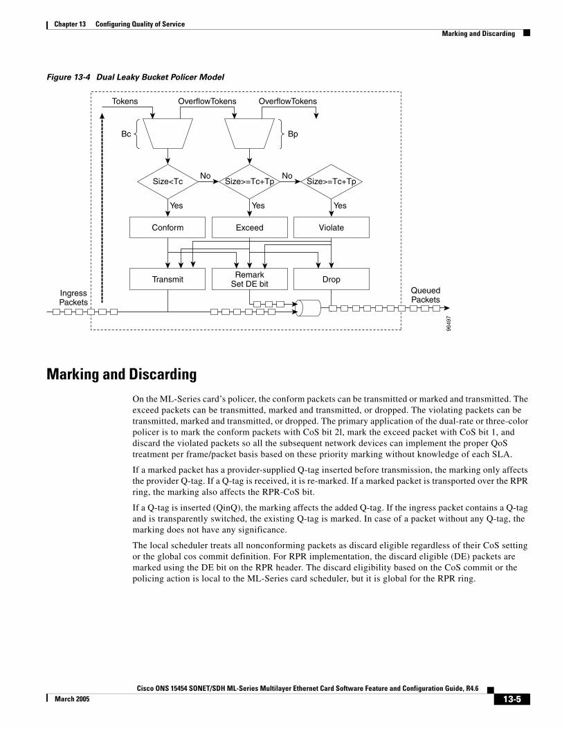
Chapter 13 Configuring Quality of ServiceMarking and Discarding
Figure 13-4 Dual Leaky Bucket Policer Model
Marking and DiscardingOn the ML-Series card’s policer, the conform packets can be transmitted or marked and transmitted. The exceed packets can be transmitted, marked and transmitted, or dropped. The violating packets can be transmitted, marked and transmitted, or dropped. The primary application of the dual-rate or three-color policer is to mark the conform packets with CoS bit 2l, mark the exceed packet with CoS bit 1, and discard the violated packets so all the subsequent network devices can implement the proper QoS treatment per frame/packet basis based on these priority marking without knowledge of each SLA.
If a marked packet has a provider-supplied Q-tag inserted before transmission, the marking only affects the provider Q-tag. If a Q-tag is received, it is re-marked. If a marked packet is transported over the RPR ring, the marking also affects the RPR-CoS bit.
If a Q-tag is inserted (QinQ), the marking affects the added Q-tag. If the ingress packet contains a Q-tag and is transparently switched, the existing Q-tag is marked. In case of a packet without any Q-tag, the marking does not have any significance.
The local scheduler treats all nonconforming packets as discard eligible regardless of their CoS setting or the global cos commit definition. For RPR implementation, the discard eligible (DE) packets are marked using the DE bit on the RPR header. The discard eligibility based on the CoS commit or the policing action is local to the ML-Series card scheduler, but it is global for the RPR ring.
9649
7
Tokens
IngressPackets
QueuedPackets
Bc
OverflowTokens
Conform
OverflowTokens
Size<Tc
Transmit
Yes
No
Bp
Exceed
Size>=Tc+Tp
RemarkSet DE bit
Yes
No
Violate
Size>=Tc+Tp
Drop
Yes
13-5Cisco ONS 15454 SONET/SDH ML-Series Multilayer Ethernet Card Software Feature and Configuration Guide, R4.6
March 2005
Chapter 13 Configuring Quality of ServiceQueuing
QueuingML-Series card queuing uses a shared buffer pool to allocate memory dynamically to different traffic queues. The ML-Series card uses a total of 12 MB memory for the buffer pool. Ethernet ports share 6 MB of the memory, and Packet-over-SONET/SDH (POS) ports share the remaining 6 MBs of memory. Memory space is allocated in 1500-byte increments.
Each queue has an upper limit on the allocated number of buffers based on the class bandwidth assignment of the queue and the number of queues configured. This upper limit is typically 30 percent to 50 percent of the shared buffer capacity. Dynamic buffer allocation to each queue can be reduced based on the number of queues needing extra buffering. The dynamic allocation mechanism provides fairness in proportion to service commitments as well as optimization of system throughput over a range of system traffic loads.
The Low Latency Queue (LLQ) is defined by setting the weight to infinity or committing 100 percent bandwidth. When a LLQ is defined, a policer should also be defined on the ingress for that specific class to limit the maximum bandwidth consumed by the LLQ; otherwise there is a potential risk of LLQ occupying the whole bandwidth and starving the other unicast queues.
The ML-Series includes support for 400 user-definable queues, which are assigned per the classification and bandwidth allocation definition. The classification used for scheduling classifies the frames/packet after the policing action, so if the policer is used to mark or change the CoS bits of the ingress frames/packet, the new values are applicable for the classification of traffic for queuing and scheduling. The ML-Series provides buffering for 4000 packets.
Scheduling Scheduling is provided by a series of schedulers that perform a WDRR as well as priority scheduling mechanisms from the queued traffic associated with each egress port.
Though ordinary round robin servicing of queues can be done in constant time, unfairness occurs when different queues use different packet sizes. Deficit Round Robin (DRR) scheduling solves this problem. If a queue was not able to send a packet in its previous round because its packet size was too large, the remainder from the previous amount of credits a queue gets in each round (quantum) is added to the quantum for the next round.
WDRR extends the quantum idea from the DRR to provide weighted throughput for each queue. Different queues have different weights, and the quantum assigned to each queue in its round is proportional to the relative weight of the queue among all the queues serviced by that scheduler.
Weights are assigned to each queue as a result of the service provisioning process. When coupled with policing and policy mapping provisioning, these weights and the WDRR scheduling process ensure that QoS commitments are provided to each service flow.
Figure 13-5 illustrates the ML-Series card’s queuing and scheduling.
13-6Cisco ONS 15454 SONET/SDH ML-Series Multilayer Ethernet Card Software Feature and Configuration Guide, R4.6
March 2005
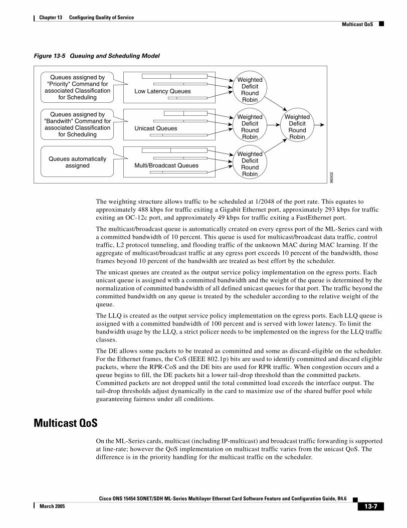
Chapter 13 Configuring Quality of ServiceMulticast QoS
Figure 13-5 Queuing and Scheduling Model
The weighting structure allows traffic to be scheduled at 1/2048 of the port rate. This equates to approximately 488 kbps for traffic exiting a Gigabit Ethernet port, approximately 293 kbps for traffic exiting an OC-12c port, and approximately 49 kbps for traffic exiting a FastEthernet port.
The multicast/broadcast queue is automatically created on every egress port of the ML-Series card with a committed bandwidth of 10 percent. This queue is used for multicast/broadcast data traffic, control traffic, L2 protocol tunneling, and flooding traffic of the unknown MAC during MAC learning. If the aggregate of multicast/broadcast traffic at any egress port exceeds 10 percent of the bandwidth, those frames beyond 10 percent of the bandwidth are treated as best effort by the scheduler.
The unicast queues are created as the output service policy implementation on the egress ports. Each unicast queue is assigned with a committed bandwidth and the weight of the queue is determined by the normalization of committed bandwidth of all defined unicast queues for that port. The traffic beyond the committed bandwidth on any queue is treated by the scheduler according to the relative weight of the queue.
The LLQ is created as the output service policy implementation on the egress ports. Each LLQ queue is assigned with a committed bandwidth of 100 percent and is served with lower latency. To limit the bandwidth usage by the LLQ, a strict policer needs to be implemented on the ingress for the LLQ traffic classes.
The DE allows some packets to be treated as committed and some as discard-eligible on the scheduler. For the Ethernet frames, the CoS (IEEE 802.1p) bits are used to identify committed and discard eligible packets, where the RPR-CoS and the DE bits are used for RPR traffic. When congestion occurs and a queue begins to fill, the DE packets hit a lower tail-drop threshold than the committed packets. Committed packets are not dropped until the total committed load exceeds the interface output. The tail-drop thresholds adjust dynamically in the card to maximize use of the shared buffer pool while guaranteeing fairness under all conditions.
Multicast QoSOn the ML-Series cards, multicast (including IP-multicast) and broadcast traffic forwarding is supported at line-rate; however the QoS implementation on multicast traffic varies from the unicast QoS. The difference is in the priority handling for the multicast traffic on the scheduler.
9650
2
Low Latency Queues
WeightedDeficitRoundRobin
Unicast Queues
WeightedDeficitRoundRobin
WeightedDeficitRoundRobin
Multi/Broadcast Queues
WeightedDeficitRoundRobin
Queues assigned by"Priority" Command for
associated Classificationfor Scheduling
Queues assigned by"Bandwith" Command forassociated Classification
for Scheduling
Queues automaticallyassigned
13-7Cisco ONS 15454 SONET/SDH ML-Series Multilayer Ethernet Card Software Feature and Configuration Guide, R4.6
March 2005
Chapter 13 Configuring Quality of ServiceControl Packets and L2 Tunneled Protocols
For unicast packets, the priority is defined by the bandwidth command, which creates a CIR for the unicast packets in a particular class.
The priority handling of multicast packets is not based on the bandwidth command. Instead, multicast frames are assigned to a queue that has a committed bandwidth of 10 percent of the port bandwidth. If the multicast and broadcast traffic exceeds 10 percent of the port bandwidth, frames exceeding 10 percent are given low priority (best effort). The 10 percent committed bandwidth for multicast is applied to the aggregate traffic and does not allow the multicast traffic of one customer to be given higher priority than another customer, unlike the QoS model for unicast traffic.
The scheduler allocates 10 percent of the bandwidth for multicast and broadcast traffic. Any other QoS implementation is not applicable for multicast and broadcast traffic except the allocation of 10 percent bandwidth for all multicast/broadcast traffics. Buffers are allocated to queues dynamically from a shared resource pool.
Control Packets and L2 Tunneled ProtocolsThe control packets originated by the ML-Series card have a higher priority than data packets. The external Layer 2 and Layer 3 control packets are handled as data packets and assigned to broadcast queues. Bridge protocol data unit (BPDU) prioritization in the ML-Series card gives Layer 2-tunneled BPDU sent out the multicast/broadcast queue a higher discard value and therefore a higher priority than than other packets in the multicast/broadcast queue. The Ethernet CoS (IEEE 802.1p) for Layer 2-tunneled protocols can be assigned by the ML-Series card.
Priority MarkingPriority marking allows the operator to assign the IEEE 802.1p CoS bits of packets that exit the card. This marking allows the operator to use the CoS bits as a mechanism for signaling to downstream nodes the QoS treatment the packet should be given. This feature operates on the outer-most IEEE 802.1p CoS field. When used with the QinQ feature, priority marking allows the user traffic (inner Q-tag) to traverse the network transparently, while providing a means for the network to internally signal QoS treatment at Layer 2.
Priority marking follows the classification process, and therefore any of the classification criteria identified earlier can be used as the basis to set the outgoing IEEE 802.1p CoS field. For example, a specific CoS value can be mapped to a specific bridge group.
Priority marking is configured using the MQC set-cos command. If packets would otherwise leave the card without an IEEE 802.1q tag, then the set-cos command has no effect on that packet. If an IEEE 802.1q tag is inserted in the packet (either a normal tag or a QinQ tag), the inserted tag has the set-cos priority. If an IEEE 802.1q tag is present on packet ingress and retained on packet egress, the priority of that tag is modified. If the ingress interface is an QinQ access port, and the set-cos policy-map classifies based on ingress tag priority, this classifies based on the user priority. This is a way to allow the user-tag priority to determine the SP tag priority. When a packet does not match any set-cos policy-map, the priority of any preserved tag is unchanged and the priority of any inserted IEEE 802.1q tag is set to 0.
The set-cos command on the output service policy is only applied to unicast traffic. Priority marking for multicast/broadcast traffic can only be achieved by the set-cos action of the policing process on the input service policy.
13-8Cisco ONS 15454 SONET/SDH ML-Series Multilayer Ethernet Card Software Feature and Configuration Guide, R4.6
March 2005
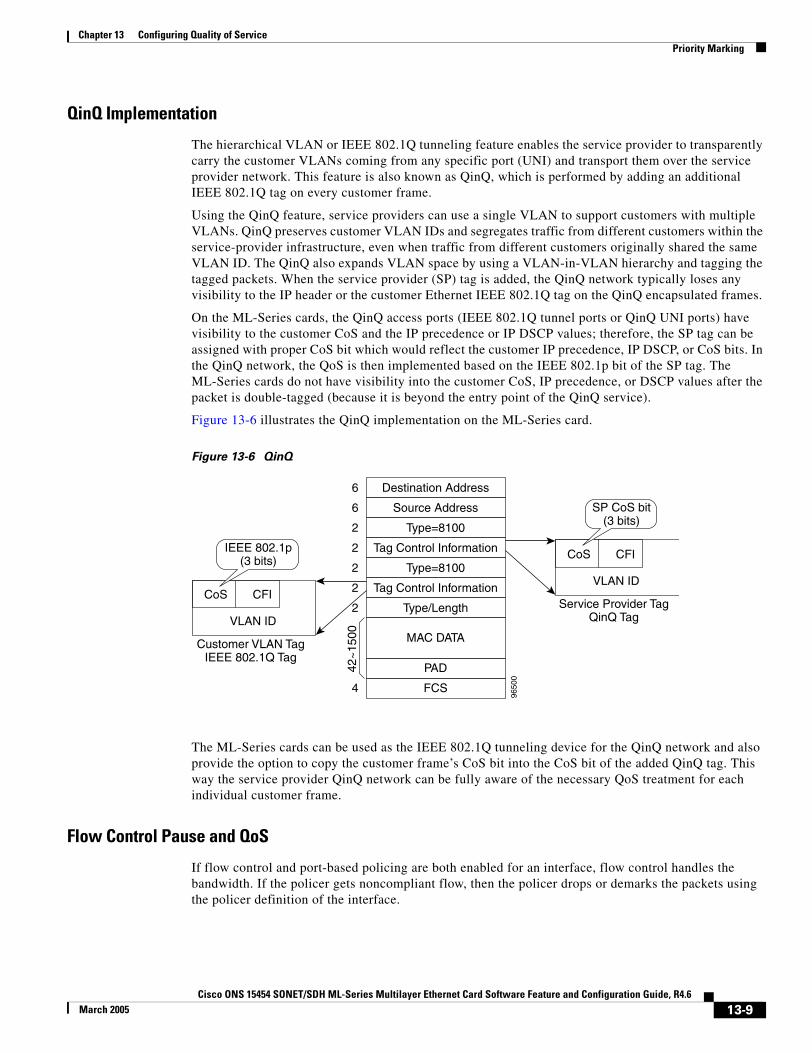
Chapter 13 Configuring Quality of ServicePriority Marking
QinQ Implementation
The hierarchical VLAN or IEEE 802.1Q tunneling feature enables the service provider to transparently carry the customer VLANs coming from any specific port (UNI) and transport them over the service provider network. This feature is also known as QinQ, which is performed by adding an additional IEEE 802.1Q tag on every customer frame.
Using the QinQ feature, service providers can use a single VLAN to support customers with multiple VLANs. QinQ preserves customer VLAN IDs and segregates traffic from different customers within the service-provider infrastructure, even when traffic from different customers originally shared the same VLAN ID. The QinQ also expands VLAN space by using a VLAN-in-VLAN hierarchy and tagging the tagged packets. When the service provider (SP) tag is added, the QinQ network typically loses any visibility to the IP header or the customer Ethernet IEEE 802.1Q tag on the QinQ encapsulated frames.
On the ML-Series cards, the QinQ access ports (IEEE 802.1Q tunnel ports or QinQ UNI ports) have visibility to the customer CoS and the IP precedence or IP DSCP values; therefore, the SP tag can be assigned with proper CoS bit which would reflect the customer IP precedence, IP DSCP, or CoS bits. In the QinQ network, the QoS is then implemented based on the IEEE 802.1p bit of the SP tag. The ML-Series cards do not have visibility into the customer CoS, IP precedence, or DSCP values after the packet is double-tagged (because it is beyond the entry point of the QinQ service).
Figure 13-6 illustrates the QinQ implementation on the ML-Series card.
Figure 13-6 QinQ
The ML-Series cards can be used as the IEEE 802.1Q tunneling device for the QinQ network and also provide the option to copy the customer frame’s CoS bit into the CoS bit of the added QinQ tag. This way the service provider QinQ network can be fully aware of the necessary QoS treatment for each individual customer frame.
Flow Control Pause and QoS
If flow control and port-based policing are both enabled for an interface, flow control handles the bandwidth. If the policer gets noncompliant flow, then the policer drops or demarks the packets using the policer definition of the interface.
9650
0
Destination Address6
Source Address6
Type=81002
Tag Control Information2
Type=81002
Tag Control Information2
Type/Length2
MAC DATA
PAD42~
1500
FCS4
Customer VLAN TagIEEE 802.1Q Tag
VLAN ID
CFICoS
IEEE 802.1p(3 bits)
Service Provider TagQinQ Tag
VLAN ID
CFICoS
SP CoS bit(3 bits)
13-9Cisco ONS 15454 SONET/SDH ML-Series Multilayer Ethernet Card Software Feature and Configuration Guide, R4.6
March 2005
Chapter 13 Configuring Quality of ServiceQoS on RPR
Note QoS and policing are not supported on the ML-Series card interface when link aggregation is used.
Note Egress shaping is not supported on the ML-Series cards.
QoS on RPRFor VLAN bridging over RPR, all ML-Series cards on the ring must be configured with the base RPR and RPR QoS configuration. SLA and bridging configurations are only needed at customer RPR access points, where IEEE 802.1q VLAN CoS is copied to the RPR CoS. This IEEE 802.1q VLAN CoS copying can be overwritten with a set-cos action command. The CoS commit rule applies at RPR ring ingress. Transit RPR ring traffic is classified on CoS only.
If the packet does not have a VLAN header, the RPR CoS for non-VLAN traffic is set using the following rules:
1. The default CoS is 0.
2. If the packet comes in with an assigned CoS, the assigned CoS replaces the default. If an IP packet originates locally, the IP precedence setting replaces the CoS setting.
3. The input policy map has a set-cos action.
4. The output policy map has a set-cos action (except for broadcast or multicast packets).
The RPR header contains a CoS value and DE indicator. The RPR DE is set for noncommitted traffic.
Configuring QoSThis section describes the tasks for configuring the ML-Series card QoS functions using the Modular Quality of Service Command-Line Interface (MQC). The ML-Series card does not support the full set of MQC functionality.
To configure and enable class-based QoS features, perform the procedures described in the following sections:
• Creating a Traffic Class, page 13-11
• Creating a Traffic Policy, page 13-12
• Attaching a Traffic Policy to an Interface, page 13-15
• Configuring CoS-based QoS, page 13-16
• Monitoring and Verifying QoS Configuration, page 13-16 (Optional)
For QoS configuration examples, see the “QoS Configuration Examples” section on page 13-17.
13-10Cisco ONS 15454 SONET/SDH ML-Series Multilayer Ethernet Card Software Feature and Configuration Guide, R4.6
March 2005

Chapter 13 Configuring Quality of ServiceCreating a Traffic Class
Creating a Traffic ClassThe class-map global configuration command is used to create a traffic class. The syntax of the class-map command is as follows:
class-map [match-any | match-all] class-map-nameno class-map [match-any | match-all] class-map-name
The match-all and match-any options need to be specified only if more than one match criterion is configured in the traffic class. The class-map match-all command is used when all of the match criteria in the traffic class must be met for a packet to match the specified traffic class. The class-map match-any command is used when only one of the match criterion in the traffic class must be met for a packet to match the specified traffic class. If neither the match-all nor match-any keyword is specified, the traffic class behaves in a manner consistent with class-map match-all command.
To create a traffic class containing match criteria, use the class-map global configuration command to specify the traffic class name, and then use the following match commands in class-map configuration mode, as needed:
Command Purpose
Router(config)# class-map class-map-name Specifies the user-defined name of the traffic class. Names can be a maximum of 40 alphanumeric characters. If match-all or match-any is not specified, traffic must match all the match criteria to be classified as part of the traffic class.
There is no default-match criteria.
Multiple match criteria are supported. The command matches either all or any of the criteria, as controlled by the match-all and match-any subcommands of the class-map command.
Router(config)# class-map match-all class-map-name
Specifies that all match criteria must be met for traffic entering the traffic class to be classified as part of the traffic class.
Router(config)# class-map match-any class-map-name
Specifies that one of the match criteria must be met for traffic entering the traffic class to be classified as part of the traffic class.
Router(config-cmap)# match any Specifies that all packets will be matched.
Router(config-cmap)# match bridge-group bridge-group-number
Specifies the bridge-group-number against whose contents packets are checked to determine if they belong to the class.
Router(config-cmap)# match cos cos-number Specifies the CoS value against whose contents packets are checked to determine if they belong to the class.
Router(config-cmap)# match input-interface interface-name
Specifies the name of the input interface used as a match criterion against which packets are checked to determine if they belong to the class.
The shared packet ring (SPR) interface, SPR1, used in RPR is a valid interface-name for the ML-Series card. For more information on the SPR interface, see Chapter 16, “Configuring Resilient Packet Ring.”
The input-interface choice is not valid when applied to the INPUT of an interface (redundant).
13-11Cisco ONS 15454 SONET/SDH ML-Series Multilayer Ethernet Card Software Feature and Configuration Guide, R4.6
March 2005
Chapter 13 Configuring Quality of ServiceCreating a Traffic Policy
Creating a Traffic PolicyTo configure a traffic policy, use the policy-map global configuration command to specify the traffic policy name, and use the following configuration commands to associate a traffic class, which was configured with the class-map command and one or more QoS features. The traffic class is associated with the traffic policy when the class command is used. The class command must be issued after entering policy-map configuration mode. After entering the class command, you are automatically in policy-map class configuration mode, which is where the QoS policies for the traffic policy are defined.
When the bandwidth or priority action is used on any class in a policy map, then there must be a class defined by the match-any command, which has a bandwidth or priority action in that policy map. This is to ensure that all traffic can be classified into a default class which has some assigned bandwidth. A minimum bandwidth can be assigned if the class is not expected to be used or no reserved bandwidth is desired for default traffic.
The QoS policies that can be applied in the traffic policy in policy-map class configuration mode are detailed in the following example:
The syntax of the policy-map command is:
policy-map policy-nameno policy-map policy-name
The syntax of the class command is:
class class-map-nameno class class-map-name
All traffic that fails to meet the matching criteria belongs to the default traffic class. The default traffic class can be configured by the user, but cannot be deleted.
To create a traffic policy, use the following commands as needed, beginning in global configuration mode:
Router(config-cmap)# match ip dscp ip-dscp-value Specifies up to eight differentiated services code point (DSCP) values used as match criteria. The value of each service code point is from 0 to 63.
Router (config-cmap)# match ip precedence ip-precedence-value
Specifies up to eight IP precedence values used as match criteria.
Command Purpose
Command Purpose
Router (config)# policy-map policy-name Specifies the name of the traffic policy to configure. Names can be a maximum of 40 alphanumeric characters.
Router (config-pmap)# class class-map-name Specifies the name of a predefined traffic class, which was configured with the class-map command, used to classify traffic to the traffic policy.
Router (config-pmap)# class class-default Specifies the default class to be created as part of the traffic policy.
13-12Cisco ONS 15454 SONET/SDH ML-Series Multilayer Ethernet Card Software Feature and Configuration Guide, R4.6
March 2005
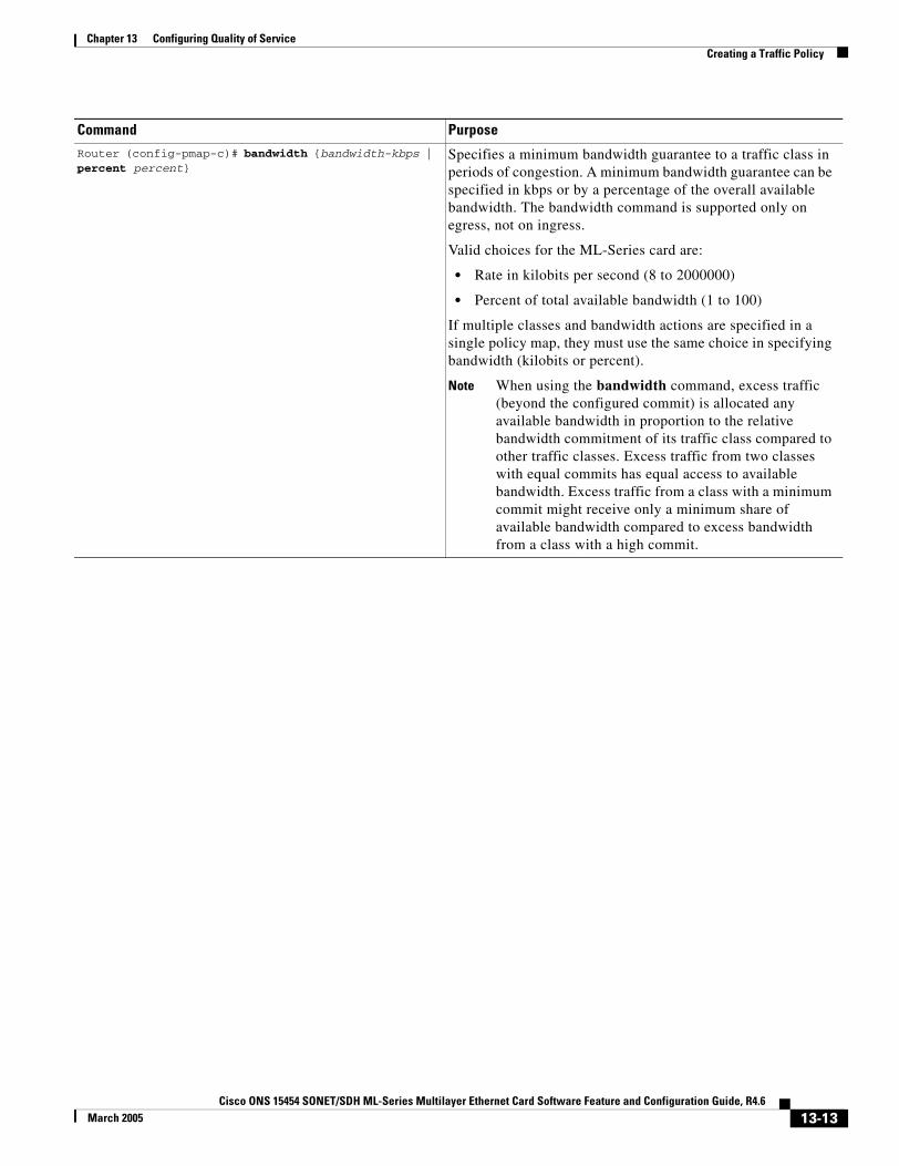
Chapter 13 Configuring Quality of ServiceCreating a Traffic Policy
Router (config-pmap-c)# bandwidth {bandwidth-kbps | percent percent}
Specifies a minimum bandwidth guarantee to a traffic class in periods of congestion. A minimum bandwidth guarantee can be specified in kbps or by a percentage of the overall available bandwidth. The bandwidth command is supported only on egress, not on ingress.
Valid choices for the ML-Series card are:
• Rate in kilobits per second (8 to 2000000)
• Percent of total available bandwidth (1 to 100)
If multiple classes and bandwidth actions are specified in a single policy map, they must use the same choice in specifying bandwidth (kilobits or percent).
Note When using the bandwidth command, excess traffic (beyond the configured commit) is allocated any available bandwidth in proportion to the relative bandwidth commitment of its traffic class compared to other traffic classes. Excess traffic from two classes with equal commits has equal access to available bandwidth. Excess traffic from a class with a minimum commit might receive only a minimum share of available bandwidth compared to excess bandwidth from a class with a high commit.
Command Purpose
13-13Cisco ONS 15454 SONET/SDH ML-Series Multilayer Ethernet Card Software Feature and Configuration Guide, R4.6
March 2005
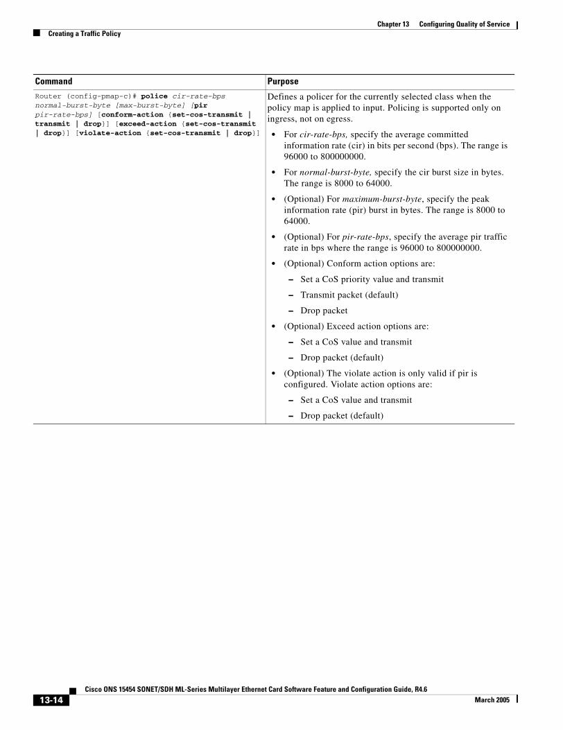
Chapter 13 Configuring Quality of ServiceCreating a Traffic Policy
Router (config-pmap-c)# police cir-rate-bps normal-burst-byte [max-burst-byte] [pir pir-rate-bps] [conform-action {set-cos-transmit | transmit | drop}] [exceed-action {set-cos-transmit | drop}] [violate-action {set-cos-transmit | drop}]
Defines a policer for the currently selected class when the policy map is applied to input. Policing is supported only on ingress, not on egress.
• For cir-rate-bps, specify the average committed information rate (cir) in bits per second (bps). The range is 96000 to 800000000.
• For normal-burst-byte, specify the cir burst size in bytes. The range is 8000 to 64000.
• (Optional) For maximum-burst-byte, specify the peak information rate (pir) burst in bytes. The range is 8000 to 64000.
• (Optional) For pir-rate-bps, specify the average pir traffic rate in bps where the range is 96000 to 800000000.
• (Optional) Conform action options are:
– Set a CoS priority value and transmit
– Transmit packet (default)
– Drop packet
• (Optional) Exceed action options are:
– Set a CoS value and transmit
– Drop packet (default)
• (Optional) The violate action is only valid if pir is configured. Violate action options are:
– Set a CoS value and transmit
– Drop packet (default)
Command Purpose
13-14Cisco ONS 15454 SONET/SDH ML-Series Multilayer Ethernet Card Software Feature and Configuration Guide, R4.6
March 2005
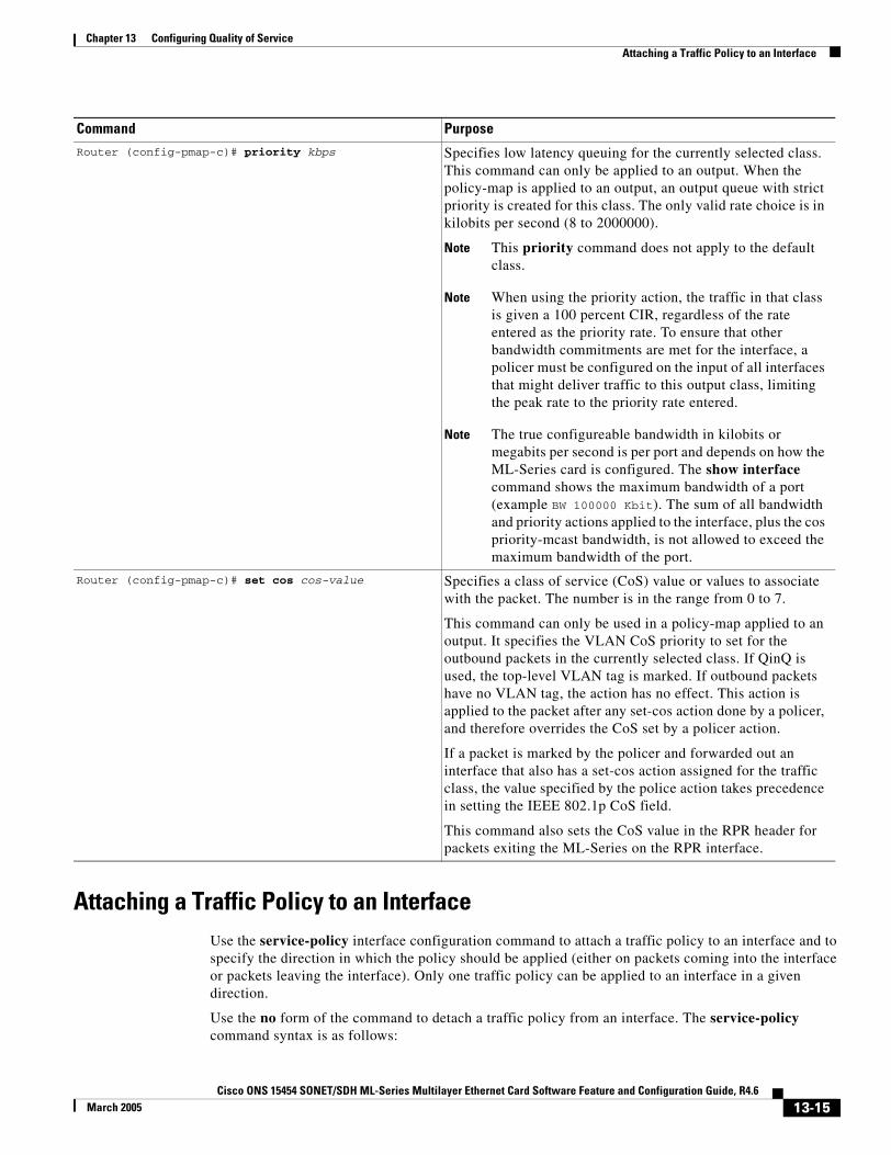
Chapter 13 Configuring Quality of ServiceAttaching a Traffic Policy to an Interface
Attaching a Traffic Policy to an InterfaceUse the service-policy interface configuration command to attach a traffic policy to an interface and to specify the direction in which the policy should be applied (either on packets coming into the interface or packets leaving the interface). Only one traffic policy can be applied to an interface in a given direction.
Use the no form of the command to detach a traffic policy from an interface. The service-policy command syntax is as follows:
Router (config-pmap-c)# priority kbps Specifies low latency queuing for the currently selected class. This command can only be applied to an output. When the policy-map is applied to an output, an output queue with strict priority is created for this class. The only valid rate choice is in kilobits per second (8 to 2000000).
Note This priority command does not apply to the default class.
Note When using the priority action, the traffic in that class is given a 100 percent CIR, regardless of the rate entered as the priority rate. To ensure that other bandwidth commitments are met for the interface, a policer must be configured on the input of all interfaces that might deliver traffic to this output class, limiting the peak rate to the priority rate entered.
Note The true configureable bandwidth in kilobits or megabits per second is per port and depends on how the ML-Series card is configured. The show interface command shows the maximum bandwidth of a port (example BW 100000 Kbit). The sum of all bandwidth and priority actions applied to the interface, plus the cos priority-mcast bandwidth, is not allowed to exceed the maximum bandwidth of the port.
Router (config-pmap-c)# set cos cos-value Specifies a class of service (CoS) value or values to associate with the packet. The number is in the range from 0 to 7.
This command can only be used in a policy-map applied to an output. It specifies the VLAN CoS priority to set for the outbound packets in the currently selected class. If QinQ is used, the top-level VLAN tag is marked. If outbound packets have no VLAN tag, the action has no effect. This action is applied to the packet after any set-cos action done by a policer, and therefore overrides the CoS set by a policer action.
If a packet is marked by the policer and forwarded out an interface that also has a set-cos action assigned for the traffic class, the value specified by the police action takes precedence in setting the IEEE 802.1p CoS field.
This command also sets the CoS value in the RPR header for packets exiting the ML-Series on the RPR interface.
Command Purpose
13-15Cisco ONS 15454 SONET/SDH ML-Series Multilayer Ethernet Card Software Feature and Configuration Guide, R4.6
March 2005
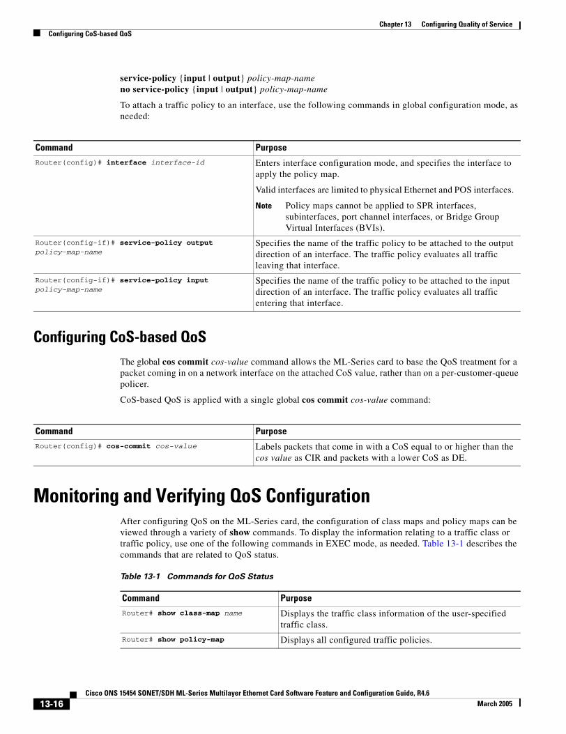
Chapter 13 Configuring Quality of ServiceConfiguring CoS-based QoS
service-policy {input | output} policy-map-nameno service-policy {input | output} policy-map-name
To attach a traffic policy to an interface, use the following commands in global configuration mode, as needed:
Configuring CoS-based QoSThe global cos commit cos-value command allows the ML-Series card to base the QoS treatment for a packet coming in on a network interface on the attached CoS value, rather than on a per-customer-queue policer.
CoS-based QoS is applied with a single global cos commit cos-value command:
Monitoring and Verifying QoS ConfigurationAfter configuring QoS on the ML-Series card, the configuration of class maps and policy maps can be viewed through a variety of show commands. To display the information relating to a traffic class or traffic policy, use one of the following commands in EXEC mode, as needed. Table 13-1 describes the commands that are related to QoS status.
Command Purpose
Router(config)# interface interface-id Enters interface configuration mode, and specifies the interface to apply the policy map.
Valid interfaces are limited to physical Ethernet and POS interfaces.
Note Policy maps cannot be applied to SPR interfaces, subinterfaces, port channel interfaces, or Bridge Group Virtual Interfaces (BVIs).
Router(config-if)# service-policy output policy-map-name
Specifies the name of the traffic policy to be attached to the output direction of an interface. The traffic policy evaluates all traffic leaving that interface.
Router(config-if)# service-policy input policy-map-name
Specifies the name of the traffic policy to be attached to the input direction of an interface. The traffic policy evaluates all traffic entering that interface.
Command Purpose
Router(config)# cos-commit cos-value Labels packets that come in with a CoS equal to or higher than the cos value as CIR and packets with a lower CoS as DE.
Table 13-1 Commands for QoS Status
Command Purpose
Router# show class-map name Displays the traffic class information of the user-specified traffic class.
Router# show policy-map Displays all configured traffic policies.
13-16Cisco ONS 15454 SONET/SDH ML-Series Multilayer Ethernet Card Software Feature and Configuration Guide, R4.6
March 2005
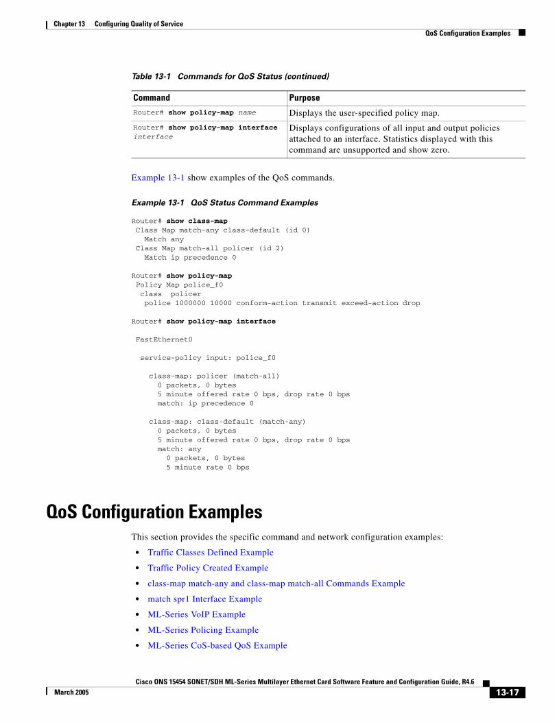
Chapter 13 Configuring Quality of ServiceQoS Configuration Examples
Example 13-1 show examples of the QoS commands.
Example 13-1 QoS Status Command Examples
Router# show class-map Class Map match-any class-default (id 0) Match any Class Map match-all policer (id 2) Match ip precedence 0
Router# show policy-map Policy Map police_f0 class policer police 1000000 10000 conform-action transmit exceed-action drop
Router# show policy-map interface
FastEthernet0
service-policy input: police_f0
class-map: policer (match-all) 0 packets, 0 bytes 5 minute offered rate 0 bps, drop rate 0 bps match: ip precedence 0
class-map: class-default (match-any) 0 packets, 0 bytes 5 minute offered rate 0 bps, drop rate 0 bps match: any 0 packets, 0 bytes 5 minute rate 0 bps
QoS Configuration ExamplesThis section provides the specific command and network configuration examples:
• Traffic Classes Defined Example
• Traffic Policy Created Example
• class-map match-any and class-map match-all Commands Example
• match spr1 Interface Example
• ML-Series VoIP Example
• ML-Series Policing Example
• ML-Series CoS-based QoS Example
Router# show policy-map name Displays the user-specified policy map.
Router# show policy-map interface interface
Displays configurations of all input and output policies attached to an interface. Statistics displayed with this command are unsupported and show zero.
Table 13-1 Commands for QoS Status (continued)
Command Purpose
13-17Cisco ONS 15454 SONET/SDH ML-Series Multilayer Ethernet Card Software Feature and Configuration Guide, R4.6
March 2005
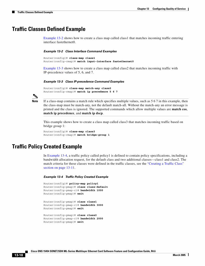
Chapter 13 Configuring Quality of ServiceTraffic Classes Defined Example
Traffic Classes Defined ExampleExample 13-2 shows how to create a class map called class1 that matches incoming traffic entering interface fastethernet0.
Example 13-2 Class Interface Command Examples
Router(config)# class-map class1Router(config-cmap)# match input-interface fastethernet0
Example 13-3 shows how to create a class map called class2 that matches incoming traffic with IP-precedence values of 5, 6, and 7.
Example 13-3 Class IP-precedence Command Examples
Router(config)# class-map match-any class2Router(config-cmap)# match ip precedence 5 6 7
Note If a class-map contains a match rule which specifies multiple values, such as 5 6 7 in this example, then the class-map must be match-any, not the default match-all. Without the match-any an error message is printed and the class is ignored. The supported commands which allow multiple values are match cos, match ip precedence, and match ip dscp.
This example shows how to create a class map called class3 that matches incoming traffic based on bridge group 1:
Router(config)# class-map class3Router(config-cmap)# match bridge-group 1
Traffic Policy Created ExampleIn Example 13-4, a traffic policy called policy1 is defined to contain policy specifications, including a bandwidth allocation request, for the default class and two additional classes—class1 and class2. The match criteria for these classes were defined in the traffic classes, see the “Creating a Traffic Class” section on page 13-11.
Example 13-4 Traffic Policy Created Example
Router(config)# policy-map policy1Router(config-pmap)# class class-defaultRouter(config-pmap-c)# bandwidth 1000 Router(config-pmap)# exit
Router(config-pmap)# class class1Router(config-pmap-c)# bandwidth 3000 Router(config-pmap)# exit Router(config-pmap)# class class2Router(config-pmap-c)# bandwidth 2000Router(config-pmap)# exit
13-18Cisco ONS 15454 SONET/SDH ML-Series Multilayer Ethernet Card Software Feature and Configuration Guide, R4.6
March 2005
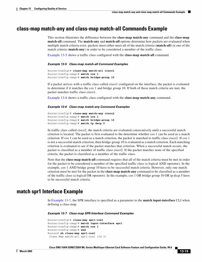
Chapter 13 Configuring Quality of Serviceclass-map match-any and class-map match-all Commands Example
class-map match-any and class-map match-all Commands ExampleThis section illustrates the difference between the class-map match-any command and the class-map match-all command. The match-any and match-all options determine how packets are evaluated when multiple match criteria exist. packets must either meet all of the match criteria (match-all) or one of the match criteria (match-any) in order to be considered a member of the traffic class.
Example 13-5 shows a traffic class configured with the class-map match-all command.
Example 13-5 Class-map match-all Command Examples
Router(config)# class-map match-all cisco1Router(config-cmap)# match cos 1Router(config-cmap)# match bridge-group 10
If a packet arrives with a traffic class called cisco1 configured on the interface, the packet is evaluated to determine if it matches the cos 1 and bridge group 10. If both of these match criteria are met, the packet matches traffic class cisco1.
Example 13-6 shows a traffic class configured with the class-map match-any command.
Example 13-6 Class-map match-any Command Examples
Router(config)# class-map match-any cisco2Router(config-cmap)# match cos 1Router(config-cmap)# match bridge-group 10Router(config-cmap)# match ip dscp 5
In traffic class called cisco2, the match criteria are evaluated consecutively until a successful match criterion is located. The packet is first evaluated to the determine whether cos 1 can be used as a match criterion. If cos 1 can be used as a match criterion, the packet is matched to traffic class cisco2. If cos 1 is not a successful match criterion, then bridge-group 10 is evaluated as a match criterion. Each matching criterion is evaluated to see if the packet matches that criterion. When a successful match occurs, the packet is classified as a member of traffic class cisco2. If the packet matches none of the specified criteria, the packet is classified as a member of the traffic class.
Note that the class-map match-all command requires that all of the match criteria must be met in order for the packet to be considered a member of the specified traffic class (a logical AND operator). In the example, cos 1 AND bridge group 10 have to be successful match criteria. However, only one match criterion must be met for the packet in the class-map match-any command to be classified as a member of the traffic class (a logical OR operator). In the example, cos 1 OR bridge group 10 OR ip dscp 5 have to be successful match criteria.
match spr1 Interface ExampleIn Example 13-7, the SPR interface is specified as a parameter to the match input-interface CLI when defining a class-map.
Example 13-7 Class-map SPR Interface Command Examples
Router(config)# class-map spr1-cos1Router(config-cmap)# match input-interface spr1Router(config-cmap)# match cos 1Router(config-cmap)# endRouter# sh class-map spr1-cos1 Class Map match-all spr1-cos1 (id 3)
13-19Cisco ONS 15454 SONET/SDH ML-Series Multilayer Ethernet Card Software Feature and Configuration Guide, R4.6
March 2005
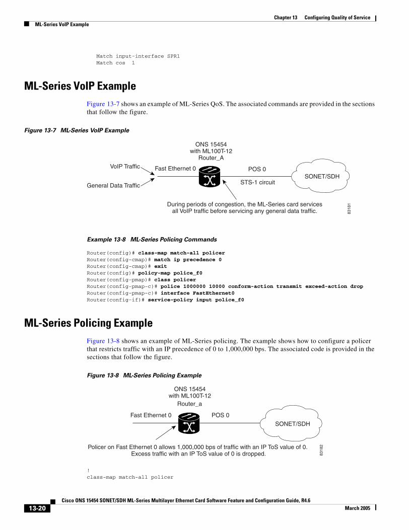
Chapter 13 Configuring Quality of ServiceML-Series VoIP Example
Match input-interface SPR1 Match cos 1
ML-Series VoIP ExampleFigure 13-7 shows an example of ML-Series QoS. The associated commands are provided in the sections that follow the figure.
Figure 13-7 ML-Series VoIP Example
Example 13-8 ML-Series Policing Commands
Router(config)# class-map match-all policerRouter(config-cmap)# match ip precedence 0Router(config-cmap)# exitRouter(config)# policy-map police_f0Router(config-pmap)# class policerRouter(config-pmap-c)# police 1000000 10000 conform-action transmit exceed-action dropRouter(config-pmap-c)# interface FastEthernet0Router(config-if)# service-policy input police_f0
ML-Series Policing ExampleFigure 13-8 shows an example of ML-Series policing. The example shows how to configure a policer that restricts traffic with an IP precedence of 0 to 1,000,000 bps. The associated code is provided in the sections that follow the figure.
Figure 13-8 ML-Series Policing Example
!class-map match-all policer
ONS 15454with ML100T-12
Router_A
Fast Ethernet 0 POS 0SONET/SDH
STS-1 circuit
VoIP Traffic
General Data Traffic
During periods of congestion, the ML-Series card services all VoIP traffic before servicing any general data traffic. 83
181
ONS 15454with ML100T-12
Fast Ethernet 0 POS 0
Router_a
Policer on Fast Ethernet 0 allows 1,000,000 bps of traffic with an IP ToS value of 0. Excess traffic with an IP ToS value of 0 is dropped.
SONET/SDH
8318
2
13-20Cisco ONS 15454 SONET/SDH ML-Series Multilayer Ethernet Card Software Feature and Configuration Guide, R4.6
March 2005
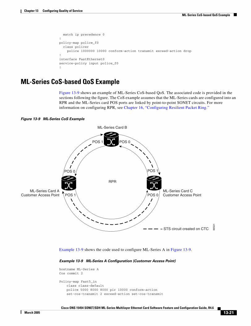
Chapter 13 Configuring Quality of ServiceML-Series CoS-based QoS Example
match ip precedence 0!policy-map police_f0 class policer police 1000000 10000 conform-action transmit exceed-action drop!interface FastEthernet0service-policy input police_f0!
ML-Series CoS-based QoS ExampleFigure 13-9 shows an example of ML-Series CoS-based QoS. The associated code is provided in the sections following the figure. The CoS example assumes that the ML-Series cards are configured into an RPR and the ML-Series card POS ports are linked by point-to-point SONET circuits. For more information on configuring RPR, see Chapter 16, “Configuring Resilient Packet Ring.”
Figure 13-9 ML-Series CoS Example
Example 13-9 shows the code used to configure ML-Series A in Figure 13-9.
Example 13-9 ML-Series A Configuration (Customer Access Point)
hostname ML-Series ACos commit 2
Policy-map Fast5_inclass class-defaultpolice 5000 8000 8000 pir 10000 conform-actionset-cos-transmit 2 exceed-action set-cos-transmit
RPR
POS 1 POS 0
POS 0
POS 0
POS 1
POS 1
= STS circuit created on CTC
ML-Series Card B
9650
1
ML-Series Card C Customer Access Point
ML-Series Card ACustomer Access Point
13-21Cisco ONS 15454 SONET/SDH ML-Series Multilayer Ethernet Card Software Feature and Configuration Guide, R4.6
March 2005
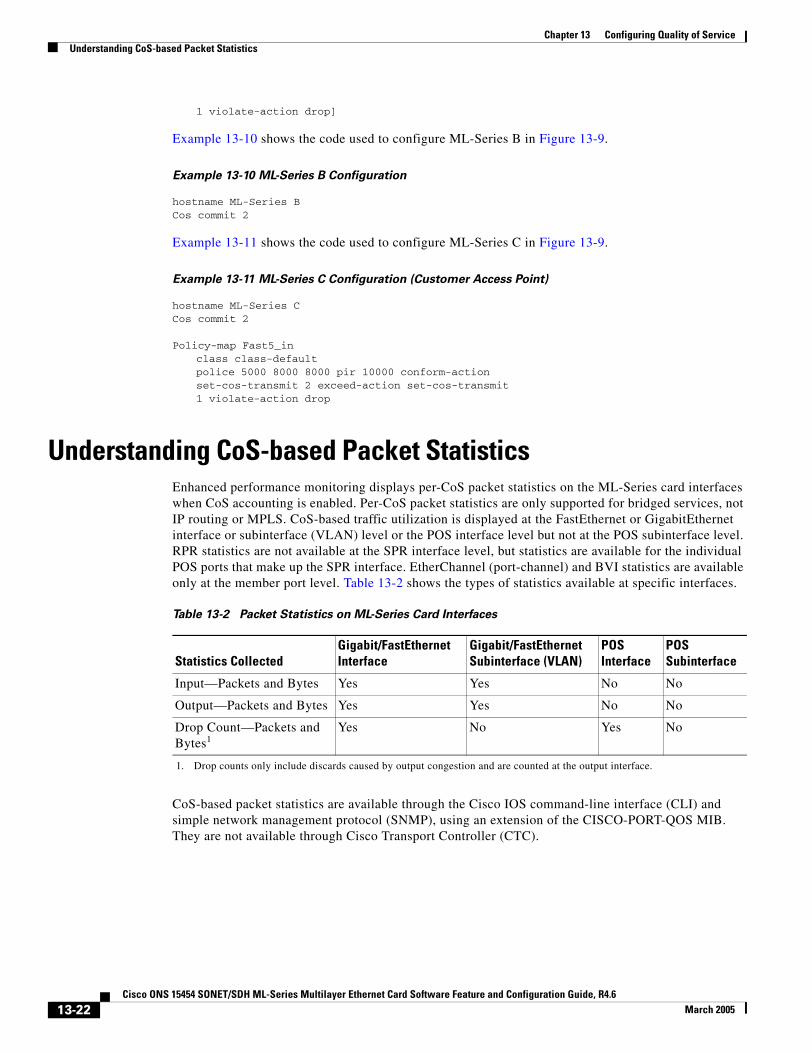
Chapter 13 Configuring Quality of ServiceUnderstanding CoS-based Packet Statistics
1 violate-action drop]
Example 13-10 shows the code used to configure ML-Series B in Figure 13-9.
Example 13-10 ML-Series B Configuration
hostname ML-Series BCos commit 2
Example 13-11 shows the code used to configure ML-Series C in Figure 13-9.
Example 13-11 ML-Series C Configuration (Customer Access Point)
hostname ML-Series CCos commit 2
Policy-map Fast5_inclass class-defaultpolice 5000 8000 8000 pir 10000 conform-actionset-cos-transmit 2 exceed-action set-cos-transmit1 violate-action drop
Understanding CoS-based Packet StatisticsEnhanced performance monitoring displays per-CoS packet statistics on the ML-Series card interfaces when CoS accounting is enabled. Per-CoS packet statistics are only supported for bridged services, not IP routing or MPLS. CoS-based traffic utilization is displayed at the FastEthernet or GigabitEthernet interface or subinterface (VLAN) level or the POS interface level but not at the POS subinterface level. RPR statistics are not available at the SPR interface level, but statistics are available for the individual POS ports that make up the SPR interface. EtherChannel (port-channel) and BVI statistics are available only at the member port level. Table 13-2 shows the types of statistics available at specific interfaces.
CoS-based packet statistics are available through the Cisco IOS command-line interface (CLI) and simple network management protocol (SNMP), using an extension of the CISCO-PORT-QOS MIB. They are not available through Cisco Transport Controller (CTC).
Table 13-2 Packet Statistics on ML-Series Card Interfaces
Statistics CollectedGigabit/FastEthernet Interface
Gigabit/FastEthernet Subinterface (VLAN)
POS Interface
POS Subinterface
Input—Packets and Bytes Yes Yes No No
Output—Packets and Bytes Yes Yes No No
Drop Count—Packets and Bytes1
1. Drop counts only include discards caused by output congestion and are counted at the output interface.
Yes No Yes No
13-22Cisco ONS 15454 SONET/SDH ML-Series Multilayer Ethernet Card Software Feature and Configuration Guide, R4.6
March 2005
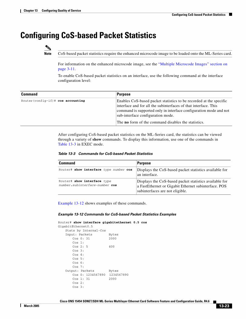
Chapter 13 Configuring Quality of ServiceConfiguring CoS-based Packet Statistics
Configuring CoS-based Packet Statistics
Note CoS-based packet statistics require the enhanced microcode image to be loaded onto the ML-Series card.
For information on the enhanced microcode image, see the “Multiple Microcode Images” section on page 3-11.
To enable CoS-based packet statistics on an interface, use the following command at the interface configuration level:
After configuring CoS-based packet statistics on the ML-Series card, the statistics can be viewed through a variety of show commands. To display this information, use one of the commands in Table 13-3 in EXEC mode.
Example 13-12 shows examples of these commands.
Example 13-12 Commands for CoS-based Packet Statistics Examples
Router# show interface gigabitethernet 0.5 cosGigabitEthernet0.5
Stats by Internal-CosInput: Packets Bytes
Cos 0: 31 2000Cos 1:Cos 2: 5 400Cos 3:Cos 4:Cos 5:Cos 6:Cos 7:
Output: Packets BytesCos 0: 1234567890 1234567890Cos 1: 31 2000Cos 2:Cos 3:
Command Purpose
Router(config-if)# cos accounting Enables CoS-based packet statistics to be recorded at the specific interface and for all the subinterfaces of that interface. This command is supported only in interface configuration mode and not sub-interface configuration mode.
The no form of the command disables the statistics.
Table 13-3 Commands for CoS-based Packet Statistics
Command Purpose
Router# show interface type number cos Displays the CoS-based packet statistics available for an interface.
Router# show interface type number.subinterface-number cos
Displays the CoS-based packet statistics available for a FastEthernet or Gigabit Ethernet subinterface. POS subinterfaces are not eligible.
13-23Cisco ONS 15454 SONET/SDH ML-Series Multilayer Ethernet Card Software Feature and Configuration Guide, R4.6
March 2005
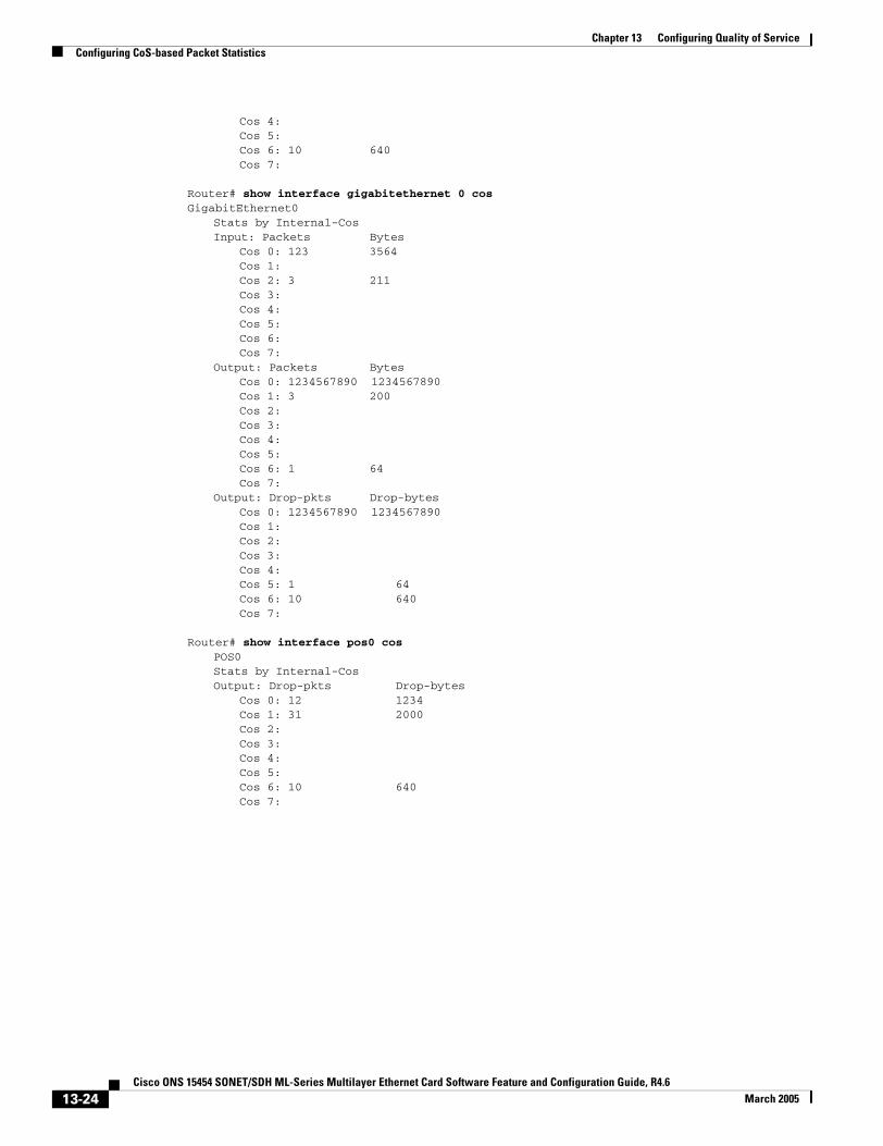
Chapter 13 Configuring Quality of ServiceConfiguring CoS-based Packet Statistics
Cos 4:Cos 5:Cos 6: 10 640Cos 7:
Router# show interface gigabitethernet 0 cosGigabitEthernet0
Stats by Internal-CosInput: Packets Bytes
Cos 0: 123 3564Cos 1:Cos 2: 3 211Cos 3:Cos 4:Cos 5:Cos 6:Cos 7:
Output: Packets BytesCos 0: 1234567890 1234567890Cos 1: 3 200Cos 2:Cos 3:Cos 4:Cos 5:Cos 6: 1 64Cos 7:
Output: Drop-pkts Drop-bytesCos 0: 1234567890 1234567890Cos 1:Cos 2:Cos 3:Cos 4:Cos 5: 1 64Cos 6: 10 640Cos 7:
Router# show interface pos0 cosPOS0Stats by Internal-CosOutput: Drop-pkts Drop-bytes
Cos 0: 12 1234Cos 1: 31 2000Cos 2:Cos 3:Cos 4:Cos 5:Cos 6: 10 640Cos 7:
13-24Cisco ONS 15454 SONET/SDH ML-Series Multilayer Ethernet Card Software Feature and Configuration Guide, R4.6
March 2005
Cisco ONS 15454 SONET/SDH ML-Series Multilayer Ethernet Card SoftwarJanuary 2005
C H A P T E R 14
Configuring the Switching Database ManagerThis chapter describes the switching database manager (SDM) features built into the ML100T-12 and ML1000-2 cards.
This chapter contains the following major sections:
• Understanding the SDM, page 14-1
• SDM Regions, page 14-1
• Configuring SDM, page 14-2
Understanding the SDM ML-Series cards use the forwarding engine and ternary content-addressable memory (TCAM) to implement high-speed forwarding. The high-speed forwarding information is maintained in TCAM. The SDM is the software subsystem that manages the switching information maintained in TCAM.
SDM organizes the switching information in TCAM into application-specific regions and configures the size of these application regions. SDM enables exact-match and longest-match address searches, which result in high-speed forwarding. SDM manages TCAM space by partitioning application-specific switching information into multiple regions.
TCAM identifies a location index associated with each packet forwarded and conveys it to the forwarding engine. The forwarding engine uses this location index to derive information associated with each forwarded packet.
The key benefits of SDM in switching are its ability to organize the switching information in TCAM into application-specific regions and its ability to configure the size of these application regions. SDM enables exact-match and longest-match address searches, which result in high-speed forwarding.
SDM RegionsSDM partitions TCAM space into multiple application-specific regions and interacts with the individual application control layers to store switching information. SDM consists of the following types of regions:
• Exact-match region—The exact-match region consists of entries for multiple application regions such as IP adjacencies.
14-1e Feature and Configuration Guide, R4.6
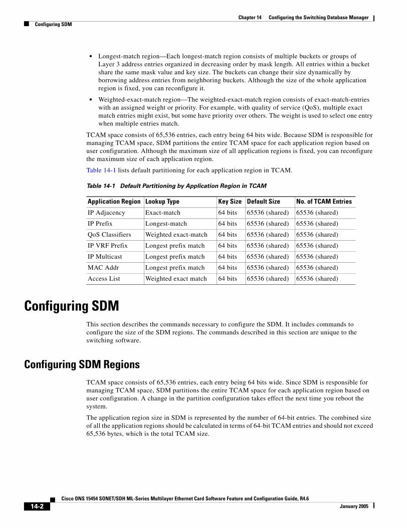
Chapter 14 Configuring the Switching Database ManagerConfiguring SDM
• Longest-match region—Each longest-match region consists of multiple buckets or groups of Layer 3 address entries organized in decreasing order by mask length. All entries within a bucket share the same mask value and key size. The buckets can change their size dynamically by borrowing address entries from neighboring buckets. Although the size of the whole application region is fixed, you can reconfigure it.
• Weighted-exact-match region—The weighted-exact-match region consists of exact-match-entries with an assigned weight or priority. For example, with quality of service (QoS), multiple exact match entries might exist, but some have priority over others. The weight is used to select one entry when multiple entries match.
TCAM space consists of 65,536 entries, each entry being 64 bits wide. Because SDM is responsible for managing TCAM space, SDM partitions the entire TCAM space for each application region based on user configuration. Although the maximum size of all application regions is fixed, you can reconfigure the maximum size of each application region.
Table 14-1 lists default partitioning for each application region in TCAM.
Configuring SDM This section describes the commands necessary to configure the SDM. It includes commands to configure the size of the SDM regions. The commands described in this section are unique to the switching software.
Configuring SDM RegionsTCAM space consists of 65,536 entries, each entry being 64 bits wide. Since SDM is responsible for managing TCAM space, SDM partitions the entire TCAM space for each application region based on user configuration. A change in the partition configuration takes effect the next time you reboot the system.
The application region size in SDM is represented by the number of 64-bit entries. The combined size of all the application regions should be calculated in terms of 64-bit TCAM entries and should not exceed 65,536 bytes, which is the total TCAM size.
Table 14-1 Default Partitioning by Application Region in TCAM
Application Region Lookup Type Key Size Default Size No. of TCAM Entries
IP Adjacency Exact-match 64 bits 65536 (shared) 65536 (shared)
IP Prefix Longest-match 64 bits 65536 (shared) 65536 (shared)
QoS Classifiers Weighted exact-match 64 bits 65536 (shared) 65536 (shared)
IP VRF Prefix Longest prefix match 64 bits 65536 (shared) 65536 (shared)
IP Multicast Longest prefix match 64 bits 65536 (shared) 65536 (shared)
MAC Addr Longest prefix match 64 bits 65536 (shared) 65536 (shared)
Access List Weighted exact match 64 bits 65536 (shared) 65536 (shared)
14-2Cisco ONS 15454 SONET/SDH ML-Series Multilayer Ethernet Card Software Feature and Configuration Guide, R4.6
January 2005
Chapter 14 Configuring the Switching Database ManagerConfiguring Access Control List Size in TCAM
To configure SDM maximum size for each application region, perform the following procedure, beginning in global configuration mode:
An example of this is shown in Example 14-1.
Example 14-1 Limiting the IP-Prefix Region to 2K Entries
Router # configure terminalRouter(config)# sdm size ip-prefix k-entries 2 Router(config)# end
To display the number of available TCAM entries, enter the show sdm size command from global configuration mode:
Router # show sdm size Active Switching Database Region Maximum Sizes : IP Adjacency : 65536 64-bit entries IP Prefix : 204864-bit entries QoS Classifiers : 65536 64-bit entries IP VRF Prefix : 65536 64-bit entries IP Multicast : 65536 64-bit entries MAC Addr : 65536 64-bit entries Access List : 6553664-bit entries
Configuring Access Control List Size in TCAMThe default maximum size of the access control list (ACL) is 65,536 64-bit entries. You can enter the sdm access-list command to limit the TCAM space for ACLs, as shown in Table 14-2.
An example of this is shown in Example 14-2.
Example 14-2 Configuring 8,192 Entries for the ACL Region in TCAM
Router# configure terminal Router(config)# sdm access-list 8192Router(config)# end
Command Purpose
Step 1 Router(config)# sdm size region-name [k-entries]number-of-entries
Sets the name of the application region whose size you want to configure. You can enter the size as multiples of 1K (that is, 1024) entries or in absolute number of entries.
Step 2 Router(config)# end Exits to privileged EXEC mode.
Table 14-2 Partitioning the TCAM Size for ACLs
Task Commandsdm access-list number-entries Sets the name of the application region for which you want to
configure the size. You can enter the size as an absolute number of entries.
14-3Cisco ONS 15454 SONET/SDH ML-Series Multilayer Ethernet Card Software Feature and Configuration Guide, R4.6
January 2005

Chapter 14 Configuring the Switching Database ManagerConfiguring Access Control List Size in TCAM
14-4Cisco ONS 15454 SONET/SDH ML-Series Multilayer Ethernet Card Software Feature and Configuration Guide, R4.6
January 2005

Cisco ONS 15454 SONET/SDH ML-Series Multilayer Ethernet Card SoftwarJanuary 2004
C H A P T E R 15
Configuring Access Control ListsThis chapter describes the access control list (ACL) features built into the ML-Series card.
This chapter contains the following major sections:
• Understanding ACLs, page 15-1
• ML-Series ACL Support, page 15-1
• Modifying ACL TCAM Size, page 15-5
Understanding ACLsACLs provide network control and security, allowing you to filter packet flow into or out of ML-Series interfaces. ACLs, which are sometimes called filters, allow you to restrict network use by certain users or devices. ACLs are created for each protocol and are applied on the interface for either inbound or outbound traffic. ACLs do not apply to outbound control plane traffic. Only one ACL filter can be applied per direction per subinterface.
When creating ACLs, you define criteria to apply to each packet processed by the ML-Series card; the ML-Series card decides whether to forward or block the packet based on whether or not the packet matches the criteria in your list. Packets that do not match any criteria in your list are automatically blocked by the implicit “deny all traffic” criteria statement at the end of every ACL.
ML-Series ACL SupportBoth control-plane and data-plane ACLs are supported on the ML-Series card:
• Control-plane ACLs: ACLs used to filter control data that is processed by the CPU of the ML-Series card (for example, distribution of routing information, Internet Group Membership Protocol (IGMP) joins, and so on).
• Data-plane ACLs: ACLs used to filter user data being routed or bridged through the ML Series in hardware (for example, denying access to a host, and so on). These ACLs are applied to an interface in the input or output direction using the ip access-group command.
The following apply when using data-plane ACLs on the ML-Series card:
• ACLs are supported on all interface types, including bridged interfaces.
• Reflexive and dynamic ACLs are not supported on the ML-Series card.
• Access violations accounting is not supported on the ML-Series card.
15-1e Feature and Configuration Guide, R4.6
Chapter 15 Configuring Access Control ListsIP ACLs
• ACL logging is supported only for packets going to the CPU, not for switched packets.
• IP standard ACLs applied to bridged egress interfaces are not supported in the data-plane. When bridging, ACLs are only supported on ingress.
IP ACLsThe following ACL styles for IP are supported:
• Standard IP ACLs: These use source addresses for matching operations.
• Extended IP ACLs (control plane only): These use source and destination addresses for matching operations and optional protocol type and port numbers for finer granularity of control.
• Named ACLs: These use source addresses for matching operations.
Note By default, the end of the ACL contains an implicit deny statement for everything if it did not find a match before reaching the end. With standard ACLs, if you omit the mask from an associated IP host address ACL specification, 0.0.0.0 is assumed to be the mask.
After creating an ACL, you must apply it to an interface, as shown in the “Applying the ACL to an Interface” section on page 15-4.
Named IP ACLs
You can identify IP ACLs with a name, but it must be an alphanumeric string. Named IP ACLs allow you to configure more IP ACLs in a router than if you used numbered ACLs. If you identify your ACL with an alphabetic rather than a numeric string, the mode and command syntax are slightly different.
Consider the following before configuring named ACLs:
• A standard ACL and an extended ACL cannot have the same name.
• Numbered ACLs are also available, as described in the “Creating Numbered Standard and Extended IP ACLs” section on page 15-3.
User Guidelines
Keep the following in mind when you configure IP network access control:
• You can program ACL entries into Ternary Content Addressable Memory (TCAM).
• You do not have to enter a deny everything statement at the end of your ACL; it is implicit.
• You can enter ACL entries in any order without any performance impact.
• For every eight TCAM entries, the ML-Series card uses one entry for TCAM management purposes.
• Do not set up conditions that result in packets getting lost. This situation can happen when a device or interface is configured to advertise services on a network that has ACLs that deny these packets.
• IP ACLs are not supported for double-tagged (QinQ) packets. They will however by applied to IP packets entering on a QinQ access port.
15-2Cisco ONS 15454 SONET/SDH ML-Series Multilayer Ethernet Card Software Feature and Configuration Guide, R4.6
January 2004

Chapter 15 Configuring Access Control ListsCreating IP ACLs
Creating IP ACLsThe following sections describe how to create numbered standard, extended, and named standard IP ACLs:
• Creating Numbered Standard and Extended IP ACLs, page 15-3
• Creating Named Standard IP ACLs, page 15-4
• Creating Named Extended IP ACLs (Control Plane Only), page 15-4
• Applying the ACL to an Interface, page 15-4
Creating Numbered Standard and Extended IP ACLs
Table 15-1 lists the global configuration commands used to create numbered standard and extended IP ACLs.
Table 15-1 Commands for Numbered Standard and Extended IP ACLs
Command Purpose
Router(config)# access-list access-list-number {deny | permit} source [source-wildcard]
Defines a standard IP ACL using a source address and wildcard.
Router(config)# access-list access-list-number {deny | permit} any
Defines a standard IP ACL using an abbreviation for the source and source mask of 0.0.0.0 255.255.255.255.
Router(config)# access-list access-list-number {deny | permit} protocol source source-wildcard destination destination-wildcard [precedence precedence] [tos tos]
Defines an extended IP ACL number and the access conditions.
Router(config)# access-list access-list-number {deny | permit} protocol any any
Defines an extended IP ACL using an abbreviation for a source and source wildcard of 0.0.0.0 255.255.255.255, and an abbreviation for a destination and destination wildcard of 0.0.0.0 255.255.255.255.
Router(config)# access-list access-list-number {deny | permit} protocol host source host destination
Defines an extended IP ACL using an abbreviation for a source and source wildcard of source 0.0.0.0, and an abbreviation for a destination and destination wildcard of destination 0.0.0.0.
15-3Cisco ONS 15454 SONET/SDH ML-Series Multilayer Ethernet Card Software Feature and Configuration Guide, R4.6
January 2004
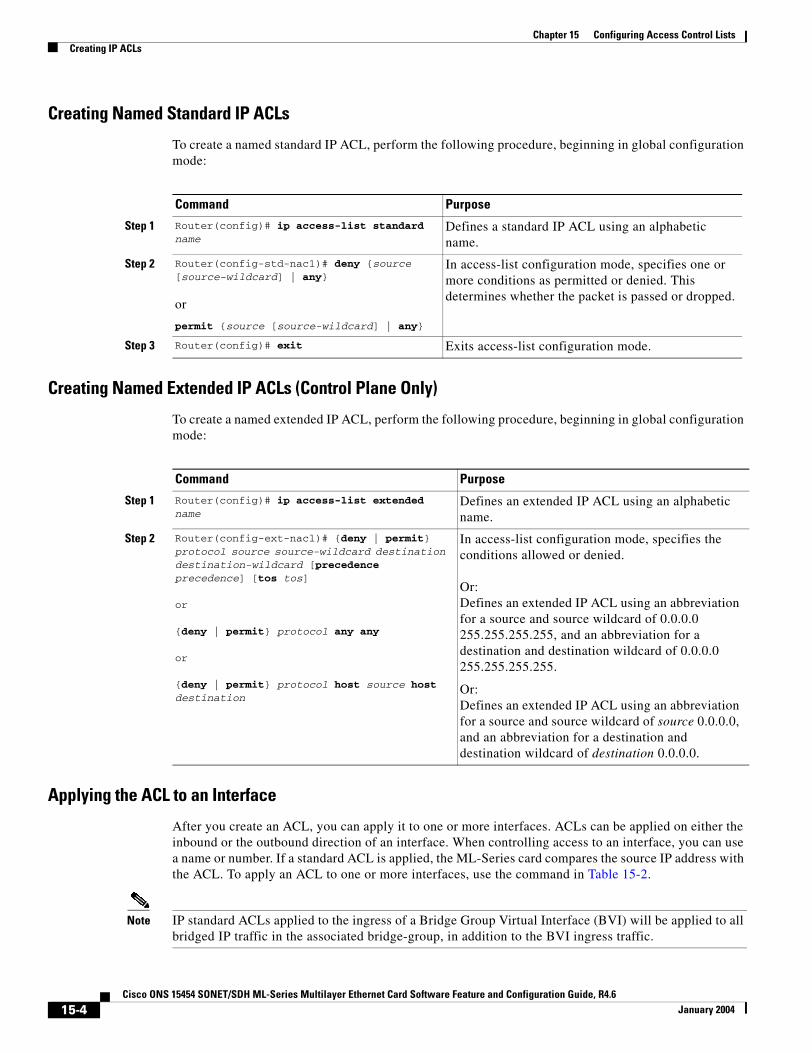
Chapter 15 Configuring Access Control ListsCreating IP ACLs
Creating Named Standard IP ACLs
To create a named standard IP ACL, perform the following procedure, beginning in global configuration mode:
Creating Named Extended IP ACLs (Control Plane Only)
To create a named extended IP ACL, perform the following procedure, beginning in global configuration mode:
Applying the ACL to an Interface
After you create an ACL, you can apply it to one or more interfaces. ACLs can be applied on either the inbound or the outbound direction of an interface. When controlling access to an interface, you can use a name or number. If a standard ACL is applied, the ML-Series card compares the source IP address with the ACL. To apply an ACL to one or more interfaces, use the command in Table 15-2.
Note IP standard ACLs applied to the ingress of a Bridge Group Virtual Interface (BVI) will be applied to all bridged IP traffic in the associated bridge-group, in addition to the BVI ingress traffic.
Command Purpose
Step 1 Router(config)# ip access-list standard name
Defines a standard IP ACL using an alphabetic name.
Step 2 Router(config-std-nac1)# deny {source [source-wildcard] | any}
or
permit {source [source-wildcard] | any}
In access-list configuration mode, specifies one or more conditions as permitted or denied. This determines whether the packet is passed or dropped.
Step 3 Router(config)# exit Exits access-list configuration mode.
Command Purpose
Step 1 Router(config)# ip access-list extended name
Defines an extended IP ACL using an alphabetic name.
Step 2 Router(config-ext-nacl)# {deny | permit} protocol source source-wildcard destination destination-wildcard [precedence precedence] [tos tos]
or
{deny | permit} protocol any any
or
{deny | permit} protocol host source host destination
In access-list configuration mode, specifies the conditions allowed or denied.
Or:Defines an extended IP ACL using an abbreviation for a source and source wildcard of 0.0.0.0 255.255.255.255, and an abbreviation for a destination and destination wildcard of 0.0.0.0 255.255.255.255.
Or:Defines an extended IP ACL using an abbreviation for a source and source wildcard of source 0.0.0.0, and an abbreviation for a destination and destination wildcard of destination 0.0.0.0.
15-4Cisco ONS 15454 SONET/SDH ML-Series Multilayer Ethernet Card Software Feature and Configuration Guide, R4.6
January 2004

Chapter 15 Configuring Access Control ListsModifying ACL TCAM Size
Modifying ACL TCAM SizeYou can change the TCAM size by entering the sdm access-list command. For more information on ACL TCAM sizes, see the “Configuring Access Control List Size in TCAM” section on page 14-3. Example 15-1 provides an example of modifying and verifying ACLs.
Note To increase the ACL TCAM size, you must decrease another region’s TCAM size, such as IP, IP multicast, or L2 switching.
Caution You will need to increase the TCAM size if you see the following error message:
Warning:Programming TCAM entries failed
Please remove last ACL command to re-activate ACL operation.
!<ACL number or name> <IP or IPX> <INPUT_ACL or OUTPUT_ACL> from TCAM group for !<interface>
Please see the documentation to see if TCAM space can be
increased on this platform to alleviate the problem.
Example 15-1 Monitor and Verify ACLs
Router# show ip access-lists 1Standard IP access list 1 permit 192.168.1.1 permit 192.168.1.2
Table 15-2 Applying ACL to Interface
Command Purpose
ip access-group {access-list-number | name} {in | out} Controls access to an interface.
15-5Cisco ONS 15454 SONET/SDH ML-Series Multilayer Ethernet Card Software Feature and Configuration Guide, R4.6
January 2004

Chapter 15 Configuring Access Control ListsModifying ACL TCAM Size
15-6Cisco ONS 15454 SONET/SDH ML-Series Multilayer Ethernet Card Software Feature and Configuration Guide, R4.6
January 2004
Cisco ONS 15454 SONET/SDH ML-Series Multilayer Ethernet Card SoftwarFebruary 2005
C H A P T E R 16
Configuring Resilient Packet RingNote The terms "Unidirectional Path Switched Ring" and "UPSR" may appear in Cisco literature. These terms do not refer to using Cisco ONS 15xxx products in a unidirectional path switched ring configuration. Rather, these terms, as well as "Path Protected Mesh Network" and "PPMN," refer generally to Cisco's path protection feature, which may be used in any topological network configuration. Cisco does not recommend using its path protection feature in any particular topological network configuration.
This chapter describes how to configure resilient packet ring (RPR) and Dual RPR Interconnect (DRPRI) for the ML-Series card.
This chapter contains the following major sections:
• Understanding RPR, page 16-1
• Configuring Point-to-Point Circuits on CTC for RPR, page 16-4
• Configuring RPR on Cisco IOS, page 16-5
• Monitoring and Verifying RPR, page 16-10
• Understanding Dual RPR Interconnect, page 16-10
• Configuring DRPRI, page 16-12
• Monitoring and Verifying DRPRI, page 16-17
Understanding RPRRPR is an emerging network architecture designed for metro fiber ring networks. This new MAC protocol is designed to overcome the limitations of IEEE 802.1D Spanning Tree Protocol (STP), IEEE 802.1W Rapid Spanning Tree Protocol (RSTP), and SONET/SDH in packet-based networks. RPR operates at the Layer 2 level and is compatible with Ethernet and SONET/SDH.
The ML-Series card’s RPR relies on the quality of service (QoS) features of the ML-Series card for efficient bandwidth utilization with service level agreement (SLA) support. ML-Series card QoS mechanisms apply to all SONET/SDH traffic on the ML-Series card, whether passed-through, bridged, or stripped.
When an ML-Series card is configured with RPR and made part of a shared packet ring (SPR), the ML-Series card assumes it is part of a ring. If a packet is not destined for devices attached to the specific ML-Series, the ML-Series card simply continues to forward this transit traffic along the SONET/SDH circuit relying on the circular path of the ring architecture to guarantee the packet will eventually arrive
16-1e Feature and Configuration Guide, R4.6
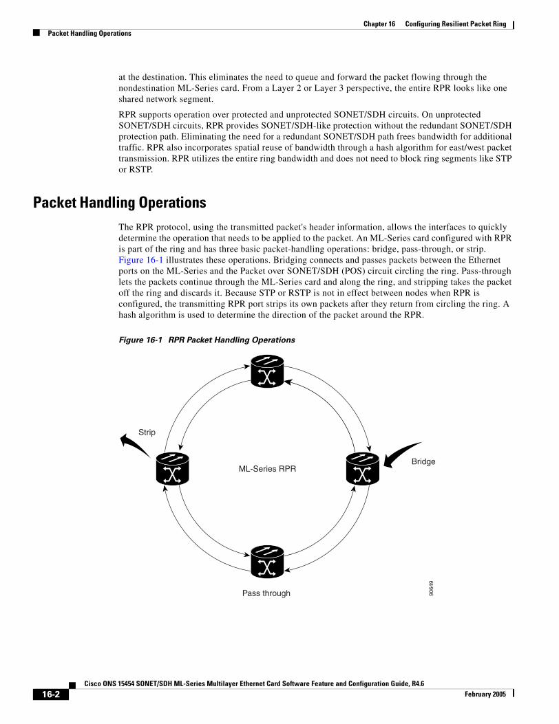
Chapter 16 Configuring Resilient Packet RingPacket Handling Operations
at the destination. This eliminates the need to queue and forward the packet flowing through the nondestination ML-Series card. From a Layer 2 or Layer 3 perspective, the entire RPR looks like one shared network segment.
RPR supports operation over protected and unprotected SONET/SDH circuits. On unprotected SONET/SDH circuits, RPR provides SONET/SDH-like protection without the redundant SONET/SDH protection path. Eliminating the need for a redundant SONET/SDH path frees bandwidth for additional traffic. RPR also incorporates spatial reuse of bandwidth through a hash algorithm for east/west packet transmission. RPR utilizes the entire ring bandwidth and does not need to block ring segments like STP or RSTP.
Packet Handling OperationsThe RPR protocol, using the transmitted packet's header information, allows the interfaces to quickly determine the operation that needs to be applied to the packet. An ML-Series card configured with RPR is part of the ring and has three basic packet-handling operations: bridge, pass-through, or strip. Figure 16-1 illustrates these operations. Bridging connects and passes packets between the Ethernet ports on the ML-Series and the Packet over SONET/SDH (POS) circuit circling the ring. Pass-through lets the packets continue through the ML-Series card and along the ring, and stripping takes the packet off the ring and discards it. Because STP or RSTP is not in effect between nodes when RPR is configured, the transmitting RPR port strips its own packets after they return from circling the ring. A hash algorithm is used to determine the direction of the packet around the RPR.
Figure 16-1 RPR Packet Handling Operations
ML-Series RPR
Strip
Bridge
Pass through 9064
9
16-2Cisco ONS 15454 SONET/SDH ML-Series Multilayer Ethernet Card Software Feature and Configuration Guide, R4.6
February 2005

Chapter 16 Configuring Resilient Packet RingRing Wrapping
Ring WrappingRPR initiates ring wraps in the event of a fiber cut, node failure, node restoration, new node insertion, or other traffic problems. This protection mechanism redirects traffic to the original destination by sending it in the opposite direction around the ring after a link state change or after receiving SONET/SDH path level alarms. Ring wrapping on the ML-Series card allows sub-50-ms convergence times. RPR convergence times are comparable to SONET/SDH and much faster than STP or RSTP.
RPR on the ML-Series card survives both unidirectional and bidirectional transmission failures within the ring. Unlike STP or RSTP, RPR restoration is scalable, increasing the number of ML-Series cards in a ring does not increase the convergence time.
Note ML-Series card RPR convergence times might exceed 50 ms in the case of multiple failures in the same ring, or if traffic passes through an ML-Series card configured with DRPRI (in active mode) during the reloading of the ML-Series card, or in the case of mismatched microcode images on ML-Series cards.
RPR will initiate ring wraps immediately (default) or delay the wrap with a configured carrier delay time. When configured to wrap traffic after the carrier delay, a POS trigger delay time should be added to the carrier delay time to estimate approximate convergence times. The default and minimum POS trigger delay time for the ML-Series card is 200 ms. A carrier delay time of 200 ms (default) and a POS trigger delay time of 200 ms (default and minimum) combine for a total convergence time of approximately 400 ms. If the carrier delay is set to 0, then the convergence time would be approximately 200 ms. Figure 16-2 illustrates ring wrapping.
Figure 16-2 RPR Ring Wrapping
Note If the carrier delay time is changed from the default, the new carrier delay time must be configured on all the ML-Series card interfaces, including the SPR, POS, and GigabitEthernet or FastEthernet interfaces.
Fiber Cut
ML-Series RPR
Ring Wrap
Ring Wrap
9065
0
16-3Cisco ONS 15454 SONET/SDH ML-Series Multilayer Ethernet Card Software Feature and Configuration Guide, R4.6
February 2005
Chapter 16 Configuring Resilient Packet RingMAC Address and VLAN Support
Note ML-Series card POS interfaces normally send PDI-P to the far-end when the POS link goes down or RPR wraps. ML-Series card POS interfaces do not send PDI-P to the far-end when PDI-P is detected, when RDI-P is being sent to the far-end or when the only defects detected are GFP LFD, GFP CSF, VCAT LOM or VCAT SQM.
MAC Address and VLAN SupportRPR improves MAC address support, because an ML-Series card does not need to learn the MAC address of pass-through packets. The ML-Series card’s MAC address table only holds the MAC IDs of packets that have been bridged or stripped by that card. This allows the collective tables of the ML-Series cards in the ring to hold a greater number of MAC addresses.
RPR also enhances VLAN support relative to STP and RSTP. In an STP and RSTP, a new VLAN must configured on all POS interfaces on the ring. In RPR, the VLAN must only be added to the configuration of those interfaces that bridge or strip packets for that VLAN. The ML-Series card still has a 255 architectural maximum limit of VLAN/bridge-group per ML-Series card. But because the ML-Series card only needs to hold the VLANs incorporating that card, the collective number of VLANs held by all the ML-Series cards in the ring can be much greater.
Configuring Point-to-Point Circuits on CTC for RPRRPR on the Cisco ONS 15454 enables two or more ML-Series cards to become one functional network segment or SPR. The bridged ML-Series cards are connected to each other through point-to-point STS/STM circuits, which use one of the first ML-Series card’s POS ports as a source and one of the second ML-Series card’s POS ports as a destination. All ML-Series cards in an SPR must be connected directly or indirectly by point-to-point circuits.
The point-to-point circuits use the ONS 15454 SONET/SDH network. Provision the point-to-point circuits using CTC or TL1 in the same manner as an ONS 15454 OC-N card STS/STM circuits. The Cisco ONS 15454 Procedure Guide or the Cisco ONS 15454 SDH Procedure Guide provides specific instructions about how to create an automatically routed optical circuit.
When configuring a point-to-point circuit on the ML-Series:
• Leave all CTC Circuit Creation Wizard options at default, except Fully Protected Path on the Circuit Routing Preferences dialog, which provides SONET/SDH protection and should be unchecked. RPR provides Layer 2 protection for SPR circuits.
• Check Using Required Nodes and Spans to route automatically in the Circuit Routing Preferences dialog box. If the source and destination nodes are adjacent on the ring, exclude all nodes except the source and destination in the Circuit Routing Preferences dialog box. This forces the circuit to be routed directly between source and destination and preserves STS/STM circuits, which would be consumed if the circuit routed through other nodes in the ring. If there is a node or nodes that do not contain an ML-Series card between the two nodes containing ML-Series card, include this node or nodes in the included nodes area in the Circuit Routing Preference dialog box, along with the source and destination nodes.
• Keep in mind that ML-Series card STS/STM circuits do not support unrelated circuit creation options, such as unidirectional traffic, creating cross-connects only (TL1-like), interdomain (unified control plane [UCP]), protected drops, or path protection selectors.
16-4Cisco ONS 15454 SONET/SDH ML-Series Multilayer Ethernet Card Software Feature and Configuration Guide, R4.6
February 2005
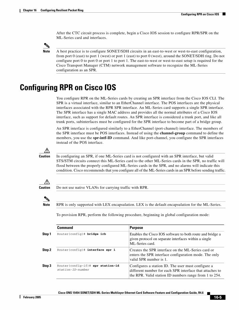
Chapter 16 Configuring Resilient Packet RingConfiguring RPR on Cisco IOS
After the CTC circuit process is complete, begin a Cisco IOS session to configure RPR/SPR on the ML-Series card and interfaces.
Note A best practice is to configure SONET/SDH circuits in an east-to-west or west-to-east configuration, from port 0 (east) to port 1 (west) or port 1 (east) to port 0 (west), around the SONET/SDH ring. Do not configure port 0 to port 0 or port 1 to port 1. The east-to-west or west-to-east setup is required for the Cisco Transport Manager (CTM) network management software to recognize the ML-Series configuration as an SPR.
Configuring RPR on Cisco IOSYou configure RPR on the ML-Series cards by creating an SPR interface from the Cisco IOS CLI. The SPR is a virtual interface, similar to an EtherChannel interface. The POS interfaces are the physical interfaces associated with the RPR SPR interface. An ML-Series card supports a single SPR interface. The SPR interface has a single MAC address and provides all the normal attributes of a Cisco IOS interface, such as support for default routes. An SPR interface is considered a trunk port, and like all trunk ports, subinterfaces must be configured for the SPR interface to become part of a bridge group.
An SPR interface is configured similarly to a EtherChannel (port-channel) interface. The members of the SPR interface must be POS interfaces. Instead of using the channel-group command to define the members, you use the spr-intf-ID command. And like port-channel, you configure the SPR interfaces instead of the POS interface.
Caution In configuring an SPR, if one ML-Series card is not configured with an SPR interface, but valid STS/STM circuits connect this ML-Series card to the other ML-Series cards in the SPR, no traffic will flood between the properly configured ML-Series cards in the SPR, and no alarms will indicate this condition. Cisco recommends that you configure all of the ML-Series cards in an SPR before sending traffic.
Caution Do not use native VLANs for carrying traffic with RPR.
Note RPR is only supported with LEX encapsulation. LEX is the default encapsulation for the ML-Series.
To provision RPR, perform the following procedure, beginning in global configuration mode:
Command Purpose
Step 1 Router(config)# bridge irb Enables the Cisco IOS software to both route and bridge a given protocol on separate interfaces within a single ML-Series card.
Step 2 Router(config)# interface spr 1 Creates the SPR interface on the ML-Series card or enters the SPR interface configuration mode. The only valid SPR number is 1.
Step 3 Router(config-if)# spr station-id station-ID-number
Configures a station ID. The user must configure a different number for each SPR interface that attaches to the RPR. Valid station ID numbers range from 1 to 254.
16-5Cisco ONS 15454 SONET/SDH ML-Series Multilayer Ethernet Card Software Feature and Configuration Guide, R4.6
February 2005
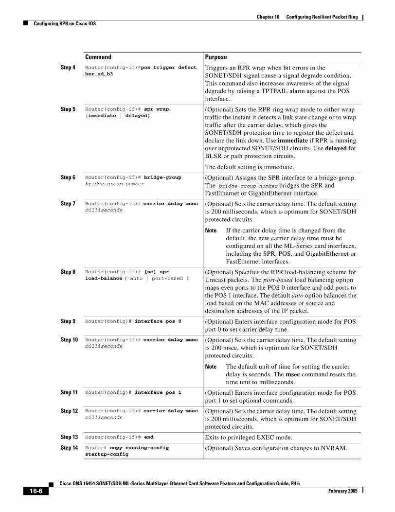
Chapter 16 Configuring Resilient Packet RingConfiguring RPR on Cisco IOS
Step 4 Router(config-if)#pos trigger defect ber_sd_b3
Triggers an RPR wrap when bit errors in the SONET/SDH signal cause a signal degrade condition. This command also increases awareness of the signal degrade by raising a TPTFAIL alarm against the POS interface.
Step 5 Router(config-if)# spr wrap {immediate | delayed}
(Optional) Sets the RPR ring wrap mode to either wrap traffic the instant it detects a link state change or to wrap traffic after the carrier delay, which gives the SONET/SDH protection time to register the defect and declare the link down. Use immediate if RPR is running over unprotected SONET/SDH circuits. Use delayed for BLSR or path protection circuits.
The default setting is immediate.
Step 6 Router(config-if)# bridge-group bridge-group-number
(Optional) Assigns the SPR interface to a bridge-group. The bridge-group-number bridges the SPR and FastEthernet or GigabitEthernet interface.
Step 7 Router(config-if)# carrier delay msec milliseconds
(Optional) Sets the carrier delay time. The default setting is 200 milliseconds, which is optimum for SONET/SDH protected circuits.
Note If the carrier delay time is changed from the default, the new carrier delay time must be configured on all the ML-Series card interfaces, including the SPR, POS, and GigabitEthernet or FastEthernet interfaces.
Step 8 Router(config-if)# [no] spr load-balance { auto | port-based }
(Optional) Specifies the RPR load-balancing scheme for Unicast packets. The port-based load balancing option maps even ports to the POS 0 interface and odd ports to the POS 1 interface. The default auto option balances the load based on the MAC addresses or source and destination addresses of the IP packet.
Step 9 Router(config)# interface pos 0 (Optional) Enters interface configuration mode for POS port 0 to set carrier delay time.
Step 10 Router(config-if)# carrier delay msec milliseconds
(Optional) Sets the carrier delay time. The default setting is 200 msec, which is optimum for SONET/SDH protected circuits.
Note The default unit of time for setting the carrier delay is seconds. The msec command resets the time unit to milliseconds.
Step 11 Router(config)# interface pos 1 (Optional) Enters interface configuration mode for POS port 1 to set optional commands.
Step 12 Router(config-if)# carrier delay msec milliseconds
(Optional) Sets the carrier delay time. The default setting is 200 milliseconds, which is optimum for SONET/SDH protected circuits.
Step 13 Router(config-if)# end Exits to privileged EXEC mode.
Step 14 Router# copy running-config startup-config
(Optional) Saves configuration changes to NVRAM.
Command Purpose
16-6Cisco ONS 15454 SONET/SDH ML-Series Multilayer Ethernet Card Software Feature and Configuration Guide, R4.6
February 2005
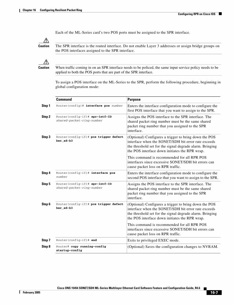
Chapter 16 Configuring Resilient Packet RingConfiguring RPR on Cisco IOS
Each of the ML-Series card’s two POS ports must be assigned to the SPR interface.
Caution The SPR interface is the routed interface. Do not enable Layer 3 addresses or assign bridge groups on the POS interfaces assigned to the SPR interface.
Caution When traffic coming in on an SPR interface needs to be policed, the same input service policy needs to be applied to both the POS ports that are part of the SPR interface.
To assign a POS interface on the ML-Series to the SPR, perform the following procedure, beginning in global configuration mode:
Command Purpose
Step 1 Router(config)# interface pos number Enters the interface configuration mode to configure the first POS interface that you want to assign to the SPR.
Step 2 Router(config-if)# spr-intf-ID shared-packet-ring-number
Assigns the POS interface to the SPR interface. The shared packet ring number must be the same shared packet ring number that you assigned to the SPR interface.
Step 3 Router(config-if)# pos trigger defect ber_sd-b3
(Optional) Configures a trigger to bring down the POS interface when the SONET/SDH bit error rate exceeds the threshold set for the signal degrade alarm. Bringing the POS interface down initiates the RPR wrap.
This command is recommended for all RPR POS interfaces since excessive SONET/SDH bit errors can cause packet loss on RPR traffic.
Step 4 Router(config-if)# interface pos number
Enters the interface configuration mode to configure the second POS interface that you want to assign to the SPR.
Step 5 Router(config-if)# spr-intf-ID shared-packet-ring-number
Assigns the POS interface to the SPR interface. The shared packet ring number must be the same shared packet ring number that you assigned to the SPR interface.
Step 6 Router(config-if)# pos trigger defect ber_sd-b3
(Optional) Configures a trigger to bring down the POS interface when the SONET/SDH bit error rate exceeds the threshold set for the signal degrade alarm. Bringing the POS interface down initiates the RPR wrap.
This command is recommended for all RPR POS interfaces since excessive SONET/SDH bit errors can cause packet loss on RPR traffic.
Step 7 Router(config-if)# end Exits to privileged EXEC mode.
Step 8 Router# copy running-config startup-config
(Optional) Saves the configuration changes to NVRAM.
16-7Cisco ONS 15454 SONET/SDH ML-Series Multilayer Ethernet Card Software Feature and Configuration Guide, R4.6
February 2005

Chapter 16 Configuring Resilient Packet RingRPR Cisco IOS Configuration Example
RPR Cisco IOS Configuration ExampleFigure 16-3 shows an example of an RPR Cisco IOS configuration. The associated code is provided in Examples 16-1, 16-2, and 16-3. The configuration assumes that ML-Series card POS ports are already linked by point-to-point SONET/SDH circuits configured through CTC.
Figure 16-3 RPR Configuration Example
Example 16-1 SPR Station-ID 1 Configuration
bridge irb!interface SPR1 no ip addressno keepalivespr station-ID 1hold-queue 150 inbridge-group 1!interface POS0 no ip addressspr-intf-ID 1!interface POS1no ip addressspr-intf-ID 1
interface GigabitEthernet0 no ip address no ip route-cachebridge-group 1
SPR 1
POS 1 POS 0
POS 0
POS 0
POS 1
POS 1
= STS circuit created on CTC
SPR Station-ID 2
SPR Station-ID 1
SPR Station-ID 3
9098
6
16-8Cisco ONS 15454 SONET/SDH ML-Series Multilayer Ethernet Card Software Feature and Configuration Guide, R4.6
February 2005
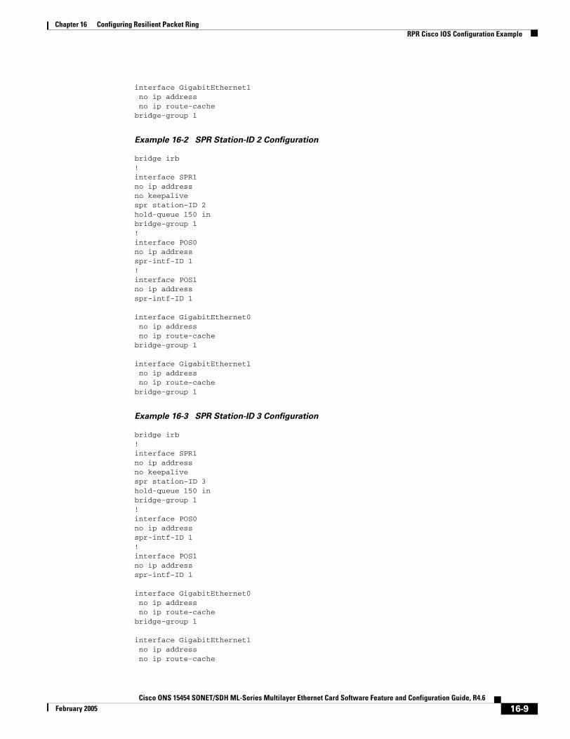
Chapter 16 Configuring Resilient Packet RingRPR Cisco IOS Configuration Example
interface GigabitEthernet1 no ip address no ip route-cachebridge-group 1
Example 16-2 SPR Station-ID 2 Configuration
bridge irb!interface SPR1 no ip addressno keepalivespr station-ID 2hold-queue 150 inbridge-group 1!interface POS0 no ip addressspr-intf-ID 1!interface POS1no ip addressspr-intf-ID 1
interface GigabitEthernet0 no ip address no ip route-cachebridge-group 1
interface GigabitEthernet1 no ip address no ip route-cachebridge-group 1
Example 16-3 SPR Station-ID 3 Configuration
bridge irb!interface SPR1 no ip addressno keepalivespr station-ID 3hold-queue 150 inbridge-group 1!interface POS0 no ip addressspr-intf-ID 1!interface POS1no ip addressspr-intf-ID 1
interface GigabitEthernet0 no ip address no ip route-cachebridge-group 1
interface GigabitEthernet1 no ip address no ip route-cache
16-9Cisco ONS 15454 SONET/SDH ML-Series Multilayer Ethernet Card Software Feature and Configuration Guide, R4.6
February 2005
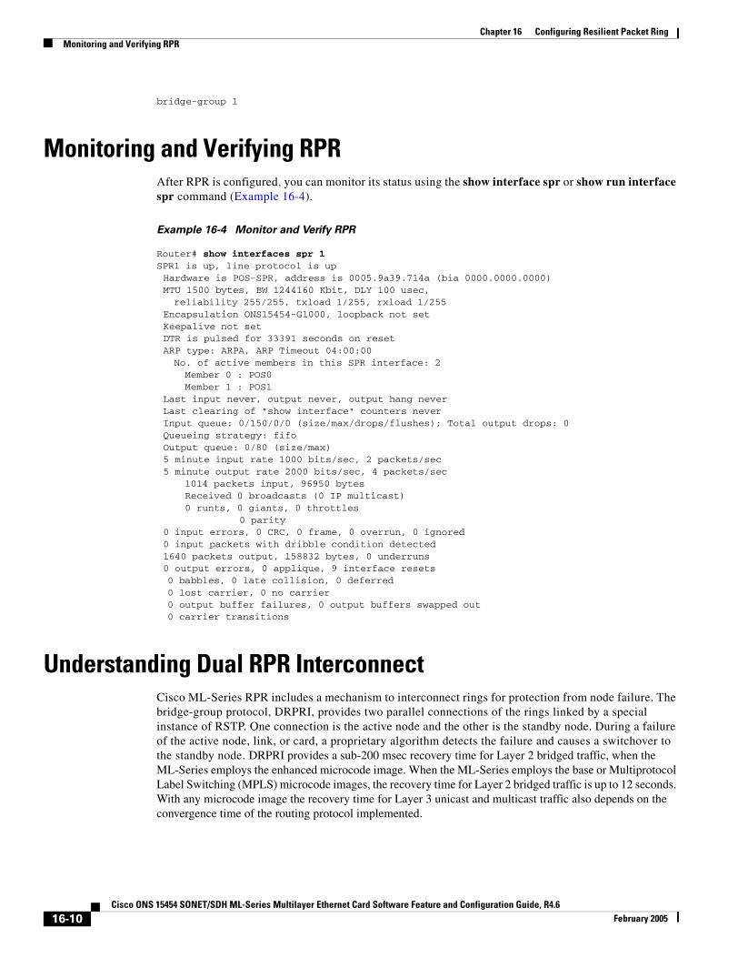
Chapter 16 Configuring Resilient Packet RingMonitoring and Verifying RPR
bridge-group 1
Monitoring and Verifying RPRAfter RPR is configured, you can monitor its status using the show interface spr or show run interface spr command (Example 16-4).
Example 16-4 Monitor and Verify RPR
Router# show interfaces spr 1SPR1 is up, line protocol is up Hardware is POS-SPR, address is 0005.9a39.714a (bia 0000.0000.0000)MTU 1500 bytes, BW 1244160 Kbit, DLY 100 usec, reliability 255/255, txload 1/255, rxload 1/255
Encapsulation ONS15454-G1000, loopback not setKeepalive not setDTR is pulsed for 33391 seconds on resetARP type: ARPA, ARP Timeout 04:00:00No. of active members in this SPR interface: 2 Member 0 : POS0 Member 1 : POS1
Last input never, output never, output hang neverLast clearing of "show interface" counters neverInput queue: 0/150/0/0 (size/max/drops/flushes); Total output drops: 0Queueing strategy: fifoOutput queue: 0/80 (size/max)5 minute input rate 1000 bits/sec, 2 packets/sec5 minute output rate 2000 bits/sec, 4 packets/sec
1014 packets input, 96950 bytesReceived 0 broadcasts (0 IP multicast)0 runts, 0 giants, 0 throttles
0 parity0 input errors, 0 CRC, 0 frame, 0 overrun, 0 ignored0 input packets with dribble condition detected1640 packets output, 158832 bytes, 0 underruns0 output errors, 0 applique, 9 interface resets0 babbles, 0 late collision, 0 deferred0 lost carrier, 0 no carrier0 output buffer failures, 0 output buffers swapped out0 carrier transitions
Understanding Dual RPR Interconnect Cisco ML-Series RPR includes a mechanism to interconnect rings for protection from node failure. The bridge-group protocol, DRPRI, provides two parallel connections of the rings linked by a special instance of RSTP. One connection is the active node and the other is the standby node. During a failure of the active node, link, or card, a proprietary algorithm detects the failure and causes a switchover to the standby node. DRPRI provides a sub-200 msec recovery time for Layer 2 bridged traffic, when the ML-Series employs the enhanced microcode image. When the ML-Series employs the base or Multiprotocol Label Switching (MPLS) microcode images, the recovery time for Layer 2 bridged traffic is up to 12 seconds. With any microcode image the recovery time for Layer 3 unicast and multicast traffic also depends on the convergence time of the routing protocol implemented.
16-10Cisco ONS 15454 SONET/SDH ML-Series Multilayer Ethernet Card Software Feature and Configuration Guide, R4.6
February 2005
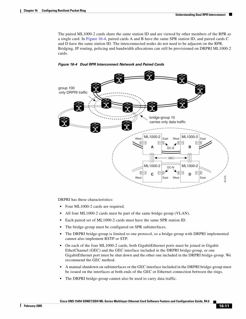
Chapter 16 Configuring Resilient Packet RingUnderstanding Dual RPR Interconnect
The paired ML1000-2 cards share the same station ID and are viewed by other members of the RPR as a single card. In Figure 16-4, paired cards A and B have the same SPR station ID, and paired cards C and D have the same station ID. The interconnected nodes do not need to be adjacent on the RPR. Bridging, IP routing, policing and bandwidth allocations can still be provisioned on DRPRI ML1000-2 cards.
Figure 16-4 Dual RPR Interconnect Network and Paired Cards
DRPRI has these characteristics:
• Four ML1000-2 cards are required.
• All four ML1000-2 cards must be part of the same bridge-group (VLAN).
• Each paired set of ML1000-2 cards must have the same SPR station ID.
• The bridge-group must be configured on SPR subinterfaces.
• The DRPRI bridge-group is limited to one protocol, so a bridge-group with DRPRI implemented cannot also implement RSTP or STP.
• On each of the four ML1000-2 cards, both GigabitEthernet ports must be joined in Gigabit EtherChannel (GEC) and the GEC interface included in the DRPRI bridge-group, or one GigabitEthernet port must be shut down and the other one included in the DRPRI bridge-group. We recommend the GEC method.
• A manual shutdown on subinterfaces or the GEC interface included in the DRPRI bridge-group must be issued on the interfaces at both ends of the GEC or Ethernet connection between the rings.
• The DRPRI bridge-group cannot also be used to carry data traffic.
GEC
9147
5
-group 100only DRPRI traffic
A
ML1000-2West East
B
ML1000-2West East
C
ML1000-2
West EastD
ML1000-2
West East
OC-N
OC-N
bridge-group 10carries only data traffic
16-11Cisco ONS 15454 SONET/SDH ML-Series Multilayer Ethernet Card Software Feature and Configuration Guide, R4.6
February 2005
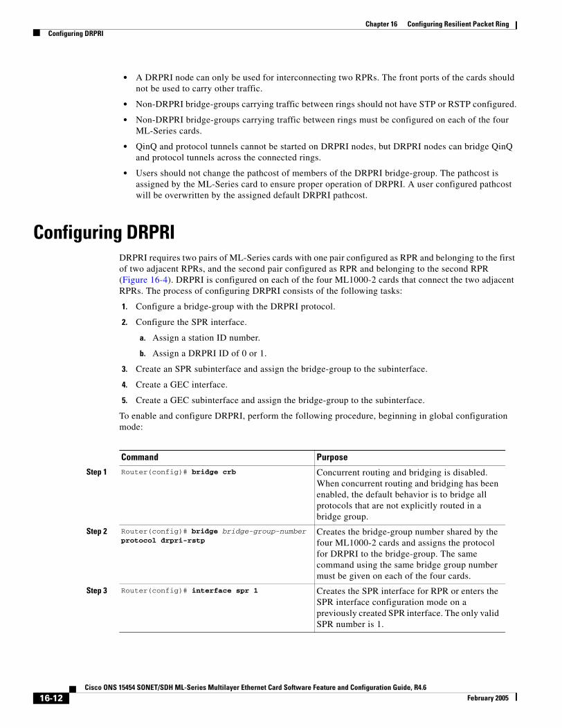
Chapter 16 Configuring Resilient Packet RingConfiguring DRPRI
• A DRPRI node can only be used for interconnecting two RPRs. The front ports of the cards should not be used to carry other traffic.
• Non-DRPRI bridge-groups carrying traffic between rings should not have STP or RSTP configured.
• Non-DRPRI bridge-groups carrying traffic between rings must be configured on each of the four ML-Series cards.
• QinQ and protocol tunnels cannot be started on DRPRI nodes, but DRPRI nodes can bridge QinQ and protocol tunnels across the connected rings.
• Users should not change the pathcost of members of the DRPRI bridge-group. The pathcost is assigned by the ML-Series card to ensure proper operation of DRPRI. A user configured pathcost will be overwritten by the assigned default DRPRI pathcost.
Configuring DRPRIDRPRI requires two pairs of ML-Series cards with one pair configured as RPR and belonging to the first of two adjacent RPRs, and the second pair configured as RPR and belonging to the second RPR (Figure 16-4). DRPRI is configured on each of the four ML1000-2 cards that connect the two adjacent RPRs. The process of configuring DRPRI consists of the following tasks:
1. Configure a bridge-group with the DRPRI protocol.
2. Configure the SPR interface.
a. Assign a station ID number.
b. Assign a DRPRI ID of 0 or 1.
3. Create an SPR subinterface and assign the bridge-group to the subinterface.
4. Create a GEC interface.
5. Create a GEC subinterface and assign the bridge-group to the subinterface.
To enable and configure DRPRI, perform the following procedure, beginning in global configuration mode:
Command Purpose
Step 1 Router(config)# bridge crb Concurrent routing and bridging is disabled. When concurrent routing and bridging has been enabled, the default behavior is to bridge all protocols that are not explicitly routed in a bridge group.
Step 2 Router(config)# bridge bridge-group-number protocol drpri-rstp
Creates the bridge-group number shared by the four ML1000-2 cards and assigns the protocol for DRPRI to the bridge-group. The same command using the same bridge group number must be given on each of the four cards.
Step 3 Router(config)# interface spr 1 Creates the SPR interface for RPR or enters the SPR interface configuration mode on a previously created SPR interface. The only valid SPR number is 1.
16-12Cisco ONS 15454 SONET/SDH ML-Series Multilayer Ethernet Card Software Feature and Configuration Guide, R4.6
February 2005
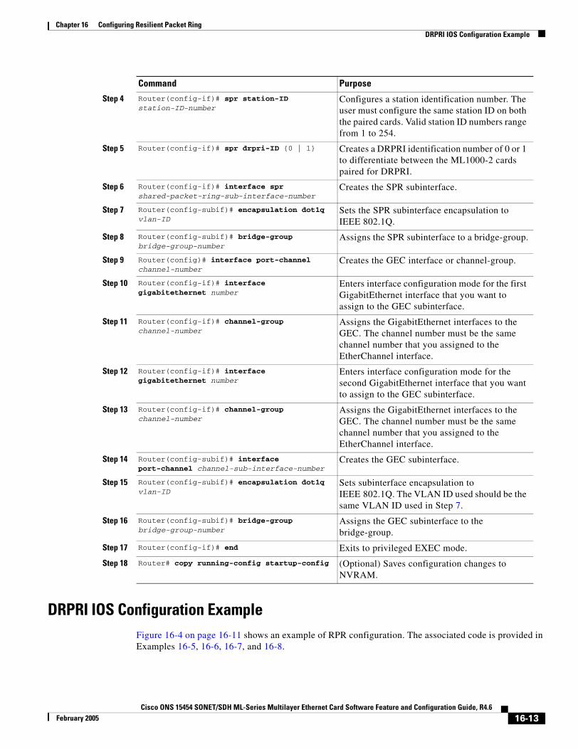
Chapter 16 Configuring Resilient Packet RingDRPRI IOS Configuration Example
DRPRI IOS Configuration ExampleFigure 16-4 on page 16-11 shows an example of RPR configuration. The associated code is provided in Examples 16-5, 16-6, 16-7, and 16-8.
Step 4 Router(config-if)# spr station-ID station-ID-number
Configures a station identification number. The user must configure the same station ID on both the paired cards. Valid station ID numbers range from 1 to 254.
Step 5 Router(config-if)# spr drpri-ID {0 | 1} Creates a DRPRI identification number of 0 or 1 to differentiate between the ML1000-2 cards paired for DRPRI.
Step 6 Router(config-if)# interface spr shared-packet-ring-sub-interface-number
Creates the SPR subinterface.
Step 7 Router(config-subif)# encapsulation dot1q vlan-ID
Sets the SPR subinterface encapsulation to IEEE 802.1Q.
Step 8 Router(config-subif)# bridge-group bridge-group-number
Assigns the SPR subinterface to a bridge-group.
Step 9 Router(config)# interface port-channel channel-number
Creates the GEC interface or channel-group.
Step 10 Router(config-if)# interface gigabitethernet number
Enters interface configuration mode for the first GigabitEthernet interface that you want to assign to the GEC subinterface.
Step 11 Router(config-if)# channel-group channel-number
Assigns the GigabitEthernet interfaces to the GEC. The channel number must be the same channel number that you assigned to the EtherChannel interface.
Step 12 Router(config-if)# interface gigabitethernet number
Enters interface configuration mode for the second GigabitEthernet interface that you want to assign to the GEC subinterface.
Step 13 Router(config-if)# channel-group channel-number
Assigns the GigabitEthernet interfaces to the GEC. The channel number must be the same channel number that you assigned to the EtherChannel interface.
Step 14 Router(config-subif)# interface port-channel channel-sub-interface-number
Creates the GEC subinterface.
Step 15 Router(config-subif)# encapsulation dot1q vlan-ID
Sets subinterface encapsulation to IEEE 802.1Q. The VLAN ID used should be the same VLAN ID used in Step 7.
Step 16 Router(config-subif)# bridge-group bridge-group-number
Assigns the GEC subinterface to the bridge-group.
Step 17 Router(config-if)# end Exits to privileged EXEC mode.
Step 18 Router# copy running-config startup-config (Optional) Saves configuration changes to NVRAM.
Command Purpose
16-13Cisco ONS 15454 SONET/SDH ML-Series Multilayer Ethernet Card Software Feature and Configuration Guide, R4.6
February 2005
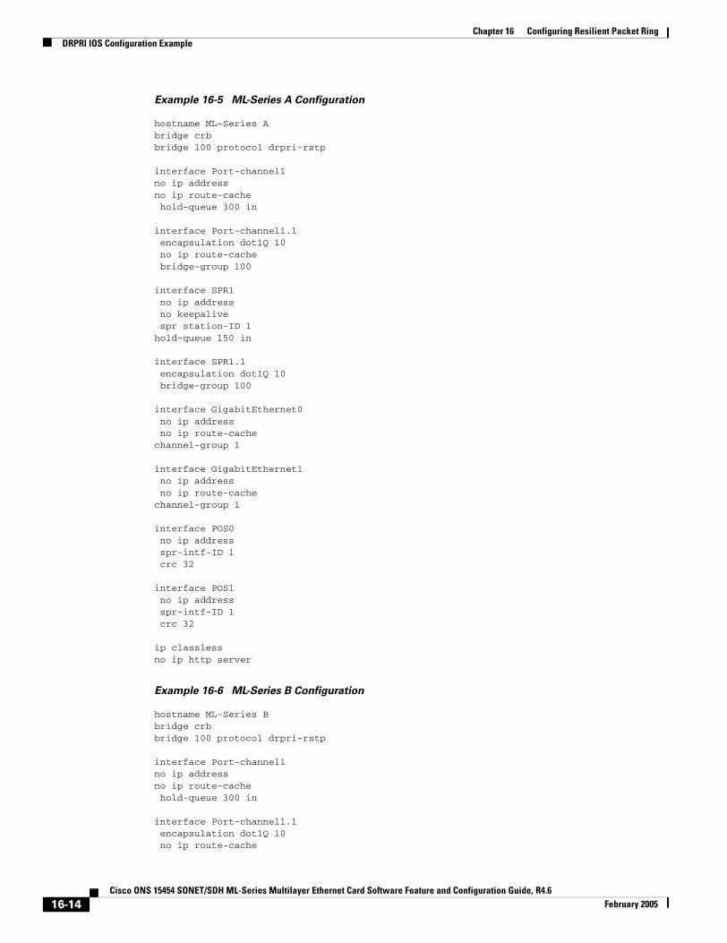
Chapter 16 Configuring Resilient Packet RingDRPRI IOS Configuration Example
Example 16-5 ML-Series A Configuration
hostname ML-Series Abridge crbbridge 100 protocol drpri-rstp
interface Port-channel1no ip addressno ip route-cache hold-queue 300 in
interface Port-channel1.1 encapsulation dot1Q 10 no ip route-cache bridge-group 100
interface SPR1 no ip address no keepalive spr station-ID 1hold-queue 150 in
interface SPR1.1 encapsulation dot1Q 10 bridge-group 100
interface GigabitEthernet0 no ip address no ip route-cachechannel-group 1
interface GigabitEthernet1 no ip address no ip route-cachechannel-group 1
interface POS0 no ip address spr-intf-ID 1 crc 32
interface POS1 no ip address spr-intf-ID 1 crc 32
ip classlessno ip http server
Example 16-6 ML-Series B Configuration
hostname ML-Series Bbridge crbbridge 100 protocol drpri-rstp
interface Port-channel1no ip addressno ip route-cache hold-queue 300 in
interface Port-channel1.1 encapsulation dot1Q 10 no ip route-cache
16-14Cisco ONS 15454 SONET/SDH ML-Series Multilayer Ethernet Card Software Feature and Configuration Guide, R4.6
February 2005

Chapter 16 Configuring Resilient Packet RingDRPRI IOS Configuration Example
bridge-group 100
interface SPR1 no ip address no keepalive spr station-ID 1spr drpr-ID 1 hold-queue 150 in
interface SPR1.1 encapsulation dot1Q 10 bridge-group 100
interface GigabitEthernet0 no ip address no ip route-cachechannel-group 1
interface GigabitEthernet1 no ip address no ip route-cachechannel-group 1
interface POS0 no ip address spr-intf-ID 1 crc 32
interface POS1 no ip address spr-intf-ID 1 crc 32
ip classlessno ip http server
Example 16-7 ML-Series C Configuration
hostname ML-Series Cbridge crbbridge 100 protocol drpri-rstp
interface Port-channel1no ip addressno ip route-cache hold-queue 300 in
interface Port-channel1.1 encapsulation dot1Q 10 no ip route-cache bridge-group 100
interface SPR1 no ip address no keepalive spr station-ID 2hold-queue 150 in
interface SPR1.1 encapsulation dot1Q 10 bridge-group 100
16-15Cisco ONS 15454 SONET/SDH ML-Series Multilayer Ethernet Card Software Feature and Configuration Guide, R4.6
February 2005
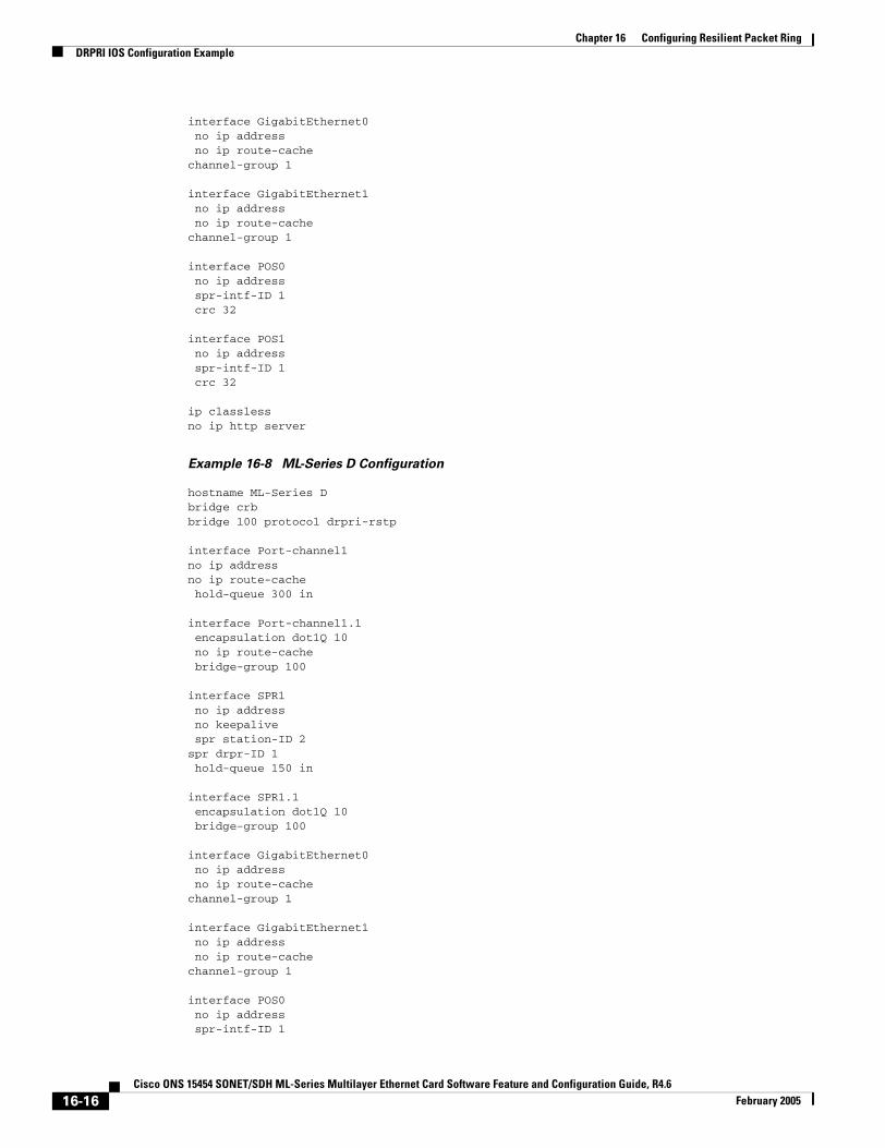
Chapter 16 Configuring Resilient Packet RingDRPRI IOS Configuration Example
interface GigabitEthernet0 no ip address no ip route-cachechannel-group 1
interface GigabitEthernet1 no ip address no ip route-cachechannel-group 1
interface POS0 no ip address spr-intf-ID 1 crc 32
interface POS1 no ip address spr-intf-ID 1 crc 32
ip classlessno ip http server
Example 16-8 ML-Series D Configuration
hostname ML-Series Dbridge crbbridge 100 protocol drpri-rstp
interface Port-channel1no ip addressno ip route-cache hold-queue 300 in
interface Port-channel1.1 encapsulation dot1Q 10 no ip route-cache bridge-group 100
interface SPR1 no ip address no keepalive spr station-ID 2spr drpr-ID 1 hold-queue 150 in
interface SPR1.1 encapsulation dot1Q 10 bridge-group 100
interface GigabitEthernet0 no ip address no ip route-cachechannel-group 1
interface GigabitEthernet1 no ip address no ip route-cachechannel-group 1
interface POS0 no ip address spr-intf-ID 1
16-16Cisco ONS 15454 SONET/SDH ML-Series Multilayer Ethernet Card Software Feature and Configuration Guide, R4.6
February 2005

Chapter 16 Configuring Resilient Packet RingMonitoring and Verifying DRPRI
crc 32
interface POS1 no ip address spr-intf-ID 1 crc 32
ip classlessno ip http server
Monitoring and Verifying DRPRIAfter DRPRI is configured, you can monitor its status using the show bridge verbose command (Example 16-9).
Example 16-9 show bridge verbose Command
Router# show bridge bridge-group-number verbose
16-17Cisco ONS 15454 SONET/SDH ML-Series Multilayer Ethernet Card Software Feature and Configuration Guide, R4.6
February 2005

Chapter 16 Configuring Resilient Packet RingMonitoring and Verifying DRPRI
16-18Cisco ONS 15454 SONET/SDH ML-Series Multilayer Ethernet Card Software Feature and Configuration Guide, R4.6
February 2005
Cisco ONS 15454 SONET/SDH ML-Series Multilayer Ethernet Card SoftwarJanuary 2004
C H A P T E R 17
Configuring Ethernet over MPLSThis chapter describes how to configure Ethernet over Multiprotocol Label Switching (EoMPLS) on the ML-Series card.
This chapter includes the following major sections:
• Understanding EoMPLS, page 17-1
• Configuring EoMPLS, page 17-4
• EoMPLS Configuration Example, page 17-9
• Monitoring and Verifying EoMPLS, page 17-11
Understanding EoMPLSEoMPLS provides a tunneling mechanism for Ethernet traffic through an MPLS-enabled Layer 3 core. It encapsulates Ethernet protocol data units (PDUs) inside MPLS packets and using label stacking forwards them across the MPLS network. EoMPLS is an Internet Engineering Task Force (IETF) standard-track protocol based on the Martini draft, specifically the draft-martini-l2circuit-encap-mpls-01 and draft-martini-l2circuit-transport-mpls-05 sections.
EoMPLS allows service providers to offer customers a virtual Ethernet line service or VLAN service using the service provider's existing MPLS backbone. It also simplifies service provider provisioning, since the provider edge customer-leading edge (PE-CLE) equipment only needs to provide Layer 2 connectivity to the connected customer edge (CE) equipment.
Figure 17-1 shows an example of EoMPLS implemented on a service provider network. In the example, the ML-Series card acts as PE-CLE equipment connecting to the Cisco GSR 12000 Series through an RPR access ring. Point–to-point service is provided to CE equipment in different sites that connect through ML-Series cards to the ML-Series card RPR access ring.
17-1e Feature and Configuration Guide, R4.6
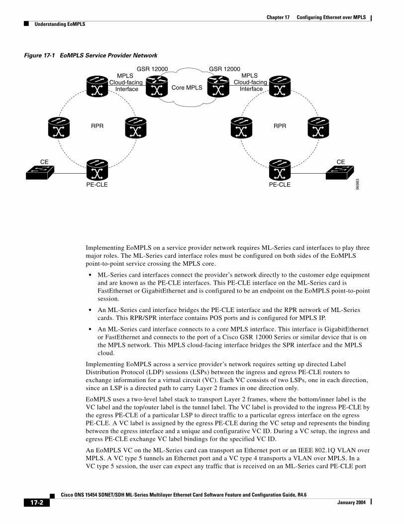
Chapter 17 Configuring Ethernet over MPLSUnderstanding EoMPLS
Figure 17-1 EoMPLS Service Provider Network
Implementing EoMPLS on a service provider network requires ML-Series card interfaces to play three major roles. The ML-Series card interface roles must be configured on both sides of the EoMPLS point-to-point service crossing the MPLS core.
• ML-Series card interfaces connect the provider’s network directly to the customer edge equipment and are known as the PE-CLE interfaces. This PE-CLE interface on the ML-Series card is FastEthernet or GigabitEthernet and is configured to be an endpoint on the EoMPLS point-to-point session.
• An ML-Series card interface bridges the PE-CLE interface and the RPR network of ML-Series cards. This RPR/SPR interface contains POS ports and is configured for MPLS IP.
• An ML-Series card interface connects to a core MPLS interface. This interface is GigabitEthernet or FastEthernet and connects to the port of a Cisco GSR 12000 Series or similar device that is on the MPLS network. This MPLS cloud-facing interface bridges the SPR interface and the MPLS cloud.
Implementing EoMPLS across a service provider’s network requires setting up directed Label Distribution Protocol (LDP) sessions (LSPs) between the ingress and egress PE-CLE routers to exchange information for a virtual circuit (VC). Each VC consists of two LSPs, one in each direction, since an LSP is a directed path to carry Layer 2 frames in one direction only.
EoMPLS uses a two-level label stack to transport Layer 2 frames, where the bottom/inner label is the VC label and the top/outer label is the tunnel label. The VC label is provided to the ingress PE-CLE by the egress PE-CLE of a particular LSP to direct traffic to a particular egress interface on the egress PE-CLE. A VC label is assigned by the egress PE-CLE during the VC setup and represents the binding between the egress interface and a unique and configurative VC ID. During a VC setup, the ingress and egress PE-CLE exchange VC label bindings for the specified VC ID.
An EoMPLS VC on the ML-Series card can transport an Ethernet port or an IEEE 802.1Q VLAN over MPLS. A VC type 5 tunnels an Ethernet port and a VC type 4 transports a VLAN over MPLS. In a VC type 5 session, the user can expect any traffic that is received on an ML-Series card PE-CLE port
Core MPLS
RPR RPR
CE CE
PE-CLE PE-CLE
MPLS Cloud-facing
Interface
MPLS Cloud-facing
Interface
GSR 12000 GSR 12000
9698
3
17-2Cisco ONS 15454 SONET/SDH ML-Series Multilayer Ethernet Card Software Feature and Configuration Guide, R4.6
January 2004
Chapter 17 Configuring Ethernet over MPLSEoMPLS Support
with an mpls l2transport route command to be tunneled to the remote egress interface on the far-end ML-Series card PE-CLE port. With a VC type 4, a user can expect the tunnel to act as physical extension to that VLAN. The EoMPLS session commands are entered on a VLAN subinterface on the PE-CLE, and only VLAN-tagged traffic received on that port will be tunneled to the remote PE-CLE.
EoMPLS SupportIn Software Release 4.6, EoMPLS on the ML-Series card has the following characteristics:
• EoMPLS is only supported on FastEthernet and GigabitEthernet interfaces or subinterfaces.
• MPLS tag switching is only supported on SPR interfaces.
• Class of service (CoS) values are mapped to the experimental (EXP) bits in the MPLS label, either statically or by using the IEEE 802.1p bits (default).
• The ingress PE-CLE ML-Series card sets the time-to-live field to 2 and the tunnel label to a value of 255.
• Ingress PE-CLE ML-Series cards set the S bit of the VC label to 1 to indicate that the VC label is at the bottom of the stack.
• Since EoMPLS traffic is carried over the RPR, whatever load balancing is applicable for the traffic ingressing RPR is also applicable for the EoMPLS traffic.
• The Ethernet over MPLS feature is part of the Cisco Any Transport over MPLS (AToM) product set. The ML-Series card implementation of EoMPLS is based on Cisco IOS 12.1 E.
• The ML-Series card hosting the EoMPLS endpoint ports must be running the MPLS microcode image to support EoMPLS. For more information on multiple microcode images, see the “Multiple Microcode Images” section on page 3-11. Other ML-Series cards in the RPR are not restricted to the MPLS microcode image.
EoMPLS RestrictionsIn Software Release 4.6, EoMPLS on the ML-Series card has the following restrictions:
• Packet-based load balancing is not supported. Instead, circuit-ID based load balancing is used.
• Zero hop or hairpin VCs are not supported. A single ML-Series card cannot be both the source and destination for a VC.
• MPLS control word for sequencing of data transmission is not supported. Packets must be received and transmitted without control word.
• Sequence checking or resequencing of EoMPLS traffic is not supported. Both depend on the control word to function.
• Maximum transmission unit (MTU) fragmentation is not supported.
• Explicit-null label for back-to-back LDP sessions is not supported.
Caution Since MTU fragmentation is not supported across the MPLS backbone, the network operator must make sure the MTU of all intermediate links between endpoints is sufficient to carry the largest Layer 2 PDU.
17-3Cisco ONS 15454 SONET/SDH ML-Series Multilayer Ethernet Card Software Feature and Configuration Guide, R4.6
January 2004
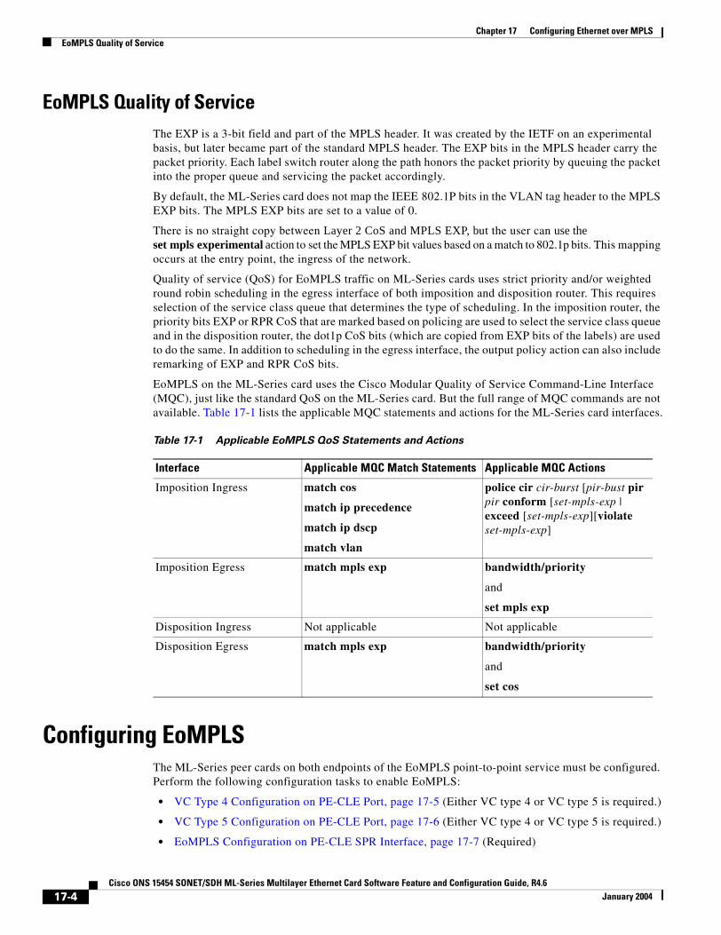
Chapter 17 Configuring Ethernet over MPLSEoMPLS Quality of Service
EoMPLS Quality of ServiceThe EXP is a 3-bit field and part of the MPLS header. It was created by the IETF on an experimental basis, but later became part of the standard MPLS header. The EXP bits in the MPLS header carry the packet priority. Each label switch router along the path honors the packet priority by queuing the packet into the proper queue and servicing the packet accordingly.
By default, the ML-Series card does not map the IEEE 802.1P bits in the VLAN tag header to the MPLS EXP bits. The MPLS EXP bits are set to a value of 0.
There is no straight copy between Layer 2 CoS and MPLS EXP, but the user can use the set mpls experimental action to set the MPLS EXP bit values based on a match to 802.1p bits. This mapping occurs at the entry point, the ingress of the network.
Quality of service (QoS) for EoMPLS traffic on ML-Series cards uses strict priority and/or weighted round robin scheduling in the egress interface of both imposition and disposition router. This requires selection of the service class queue that determines the type of scheduling. In the imposition router, the priority bits EXP or RPR CoS that are marked based on policing are used to select the service class queue and in the disposition router, the dot1p CoS bits (which are copied from EXP bits of the labels) are used to do the same. In addition to scheduling in the egress interface, the output policy action can also include remarking of EXP and RPR CoS bits.
EoMPLS on the ML-Series card uses the Cisco Modular Quality of Service Command-Line Interface (MQC), just like the standard QoS on the ML-Series card. But the full range of MQC commands are not available. Table 17-1 lists the applicable MQC statements and actions for the ML-Series card interfaces.
Configuring EoMPLSThe ML-Series peer cards on both endpoints of the EoMPLS point-to-point service must be configured. Perform the following configuration tasks to enable EoMPLS:
• VC Type 4 Configuration on PE-CLE Port, page 17-5 (Either VC type 4 or VC type 5 is required.)
• VC Type 5 Configuration on PE-CLE Port, page 17-6 (Either VC type 4 or VC type 5 is required.)
• EoMPLS Configuration on PE-CLE SPR Interface, page 17-7 (Required)
Table 17-1 Applicable EoMPLS QoS Statements and Actions
Interface Applicable MQC Match Statements Applicable MQC Actions
Imposition Ingress match cos
match ip precedence
match ip dscp
match vlan
police cir cir-burst [pir-bust pir pir conform [set-mpls-exp | exceed [set-mpls-exp][violate set-mpls-exp]
Imposition Egress match mpls exp bandwidth/priority
and
set mpls exp
Disposition Ingress Not applicable Not applicable
Disposition Egress match mpls exp bandwidth/priority
and
set cos
17-4Cisco ONS 15454 SONET/SDH ML-Series Multilayer Ethernet Card Software Feature and Configuration Guide, R4.6
January 2004
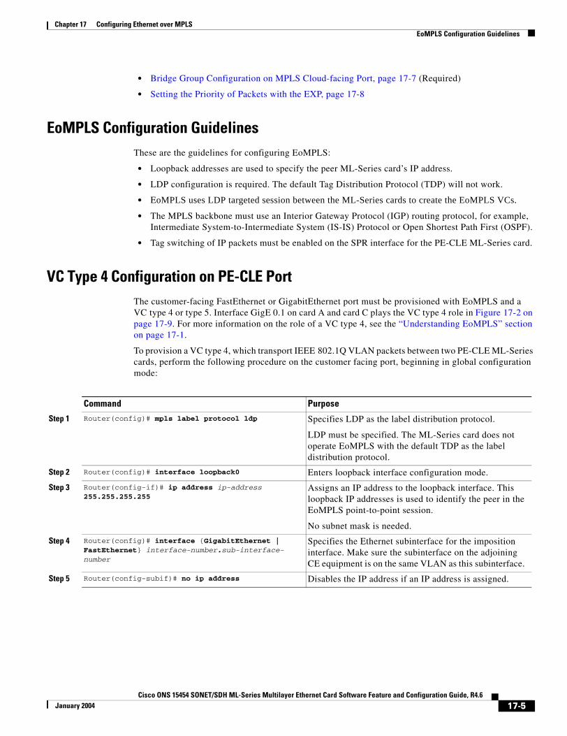
Chapter 17 Configuring Ethernet over MPLSEoMPLS Configuration Guidelines
• Bridge Group Configuration on MPLS Cloud-facing Port, page 17-7 (Required)
• Setting the Priority of Packets with the EXP, page 17-8
EoMPLS Configuration GuidelinesThese are the guidelines for configuring EoMPLS:
• Loopback addresses are used to specify the peer ML-Series card’s IP address.
• LDP configuration is required. The default Tag Distribution Protocol (TDP) will not work.
• EoMPLS uses LDP targeted session between the ML-Series cards to create the EoMPLS VCs.
• The MPLS backbone must use an Interior Gateway Protocol (IGP) routing protocol, for example, Intermediate System-to-Intermediate System (IS-IS) Protocol or Open Shortest Path First (OSPF).
• Tag switching of IP packets must be enabled on the SPR interface for the PE-CLE ML-Series card.
VC Type 4 Configuration on PE-CLE PortThe customer-facing FastEthernet or GigabitEthernet port must be provisioned with EoMPLS and a VC type 4 or type 5. Interface GigE 0.1 on card A and card C plays the VC type 4 role in Figure 17-2 on page 17-9. For more information on the role of a VC type 4, see the “Understanding EoMPLS” section on page 17-1.
To provision a VC type 4, which transport IEEE 802.1Q VLAN packets between two PE-CLE ML-Series cards, perform the following procedure on the customer facing port, beginning in global configuration mode:
Command Purpose
Step 1 Router(config)# mpls label protocol ldp Specifies LDP as the label distribution protocol.
LDP must be specified. The ML-Series card does not operate EoMPLS with the default TDP as the label distribution protocol.
Step 2 Router(config)# interface loopback0 Enters loopback interface configuration mode.
Step 3 Router(config-if)# ip address ip-address 255.255.255.255
Assigns an IP address to the loopback interface. This loopback IP addresses is used to identify the peer in the EoMPLS point-to-point session.
No subnet mask is needed.
Step 4 Router(config)# interface {GigabitEthernet | FastEthernet} interface-number.sub-interface- number
Specifies the Ethernet subinterface for the imposition interface. Make sure the subinterface on the adjoining CE equipment is on the same VLAN as this subinterface.
Step 5 Router(config-subif)# no ip address Disables the IP address if an IP address is assigned.
17-5Cisco ONS 15454 SONET/SDH ML-Series Multilayer Ethernet Card Software Feature and Configuration Guide, R4.6
January 2004
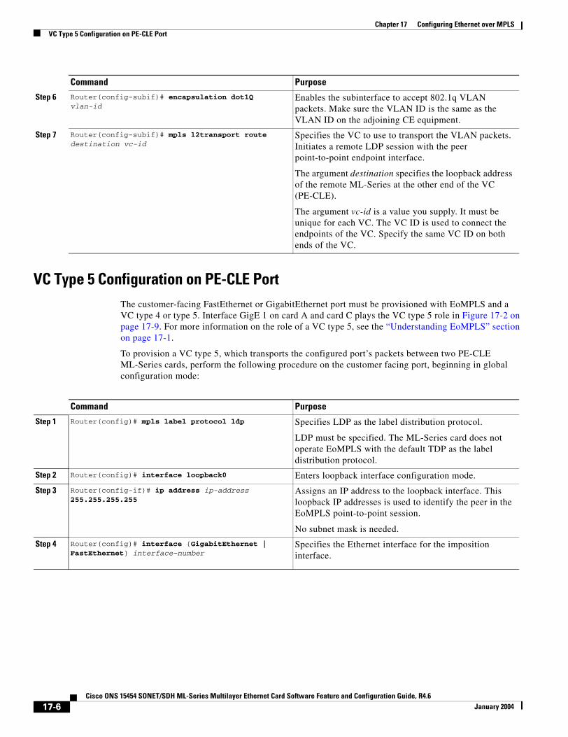
Chapter 17 Configuring Ethernet over MPLSVC Type 5 Configuration on PE-CLE Port
VC Type 5 Configuration on PE-CLE PortThe customer-facing FastEthernet or GigabitEthernet port must be provisioned with EoMPLS and a VC type 4 or type 5. Interface GigE 1 on card A and card C plays the VC type 5 role in Figure 17-2 on page 17-9. For more information on the role of a VC type 5, see the “Understanding EoMPLS” section on page 17-1.
To provision a VC type 5, which transports the configured port’s packets between two PE-CLE ML-Series cards, perform the following procedure on the customer facing port, beginning in global configuration mode:
Step 6 Router(config-subif)# encapsulation dot1Q vlan-id
Enables the subinterface to accept 802.1q VLAN packets. Make sure the VLAN ID is the same as the VLAN ID on the adjoining CE equipment.
Step 7 Router(config-subif)# mpls l2transport route destination vc-id
Specifies the VC to use to transport the VLAN packets. Initiates a remote LDP session with the peer point-to-point endpoint interface.
The argument destination specifies the loopback address of the remote ML-Series at the other end of the VC (PE-CLE).
The argument vc-id is a value you supply. It must be unique for each VC. The VC ID is used to connect the endpoints of the VC. Specify the same VC ID on both ends of the VC.
Command Purpose
Command Purpose
Step 1 Router(config)# mpls label protocol ldp Specifies LDP as the label distribution protocol.
LDP must be specified. The ML-Series card does not operate EoMPLS with the default TDP as the label distribution protocol.
Step 2 Router(config)# interface loopback0 Enters loopback interface configuration mode.
Step 3 Router(config-if)# ip address ip-address 255.255.255.255
Assigns an IP address to the loopback interface. This loopback IP addresses is used to identify the peer in the EoMPLS point-to-point session.
No subnet mask is needed.
Step 4 Router(config)# interface {GigabitEthernet | FastEthernet} interface-number
Specifies the Ethernet interface for the imposition interface.
17-6Cisco ONS 15454 SONET/SDH ML-Series Multilayer Ethernet Card Software Feature and Configuration Guide, R4.6
January 2004
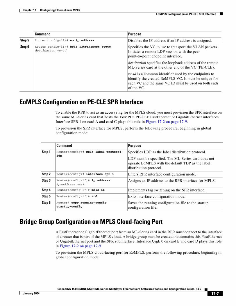
Chapter 17 Configuring Ethernet over MPLSEoMPLS Configuration on PE-CLE SPR Interface
EoMPLS Configuration on PE-CLE SPR InterfaceTo enable the RPR to act as an access ring for the MPLS cloud, you must provision the SPR interface on the same ML-Series card that hosts the EoMPLS PE-CLE FastEthernet or GigabitEthernet interfaces. Interface SPR 1 on card A and card C plays this role in Figure 17-2 on page 17-9.
To provision the SPR interface for MPLS, perform the following procedure, beginning in global configuration mode:
Bridge Group Configuration on MPLS Cloud-facing PortA FastEthernet or GigabitEthernet port from an ML-Series card in the RPR must connect to the interface of a router that is part of the MPLS cloud. A bridge group must be created that contains this FastEthernet or GigabitEthernet port and the SPR subinterface. Interface GigE 0 on card B and card D plays this role in Figure 17-2 on page 17-9.
To provision the MPLS cloud-facing port for EoMPLS, perform the following procedure, beginning in global configuration mode:
Step 5 Router(config-if)# no ip address Disables the IP address if an IP address is assigned.
Step 6 Router(config-if)# mpls l2transport route destination vc-id
Specifies the VC to use to transport the VLAN packets. Initiates a remote LDP session with the peer point-to-point endpoint interface.
destination specifies the loopback address of the remote ML-Series card at the other end of the VC (PE-CLE).
vc-id is a common identifier used by the endpoints to identify the created EoMPLS VC. It must be unique for each VC and the same VC ID must be used on both ends of the VC.
Command Purpose
Command Purpose
Step 1 Router(config)# mpls label protocol ldp
Specifies LDP as the label distribution protocol.
LDP must be specified. The ML-Series card does not operate EoMPLS with the default TDP as the label distribution protocol.
Step 2 Router(config)# interface spr 1 Enters RPR interface configuration mode.
Step 3 Router(config-if)# ip address ip-address mask
Assigns an IP address to the RPR interface for MPLS.
Step 4 Router(config-if)# mpls ip Implements tag switching on the SPR interface.
Step 5 Router(config-if)# end Exits interface configuration mode.
Step 6 Router# copy running-config startup-config
Saves the running configuration file to the startup configuration file.
17-7Cisco ONS 15454 SONET/SDH ML-Series Multilayer Ethernet Card Software Feature and Configuration Guide, R4.6
January 2004
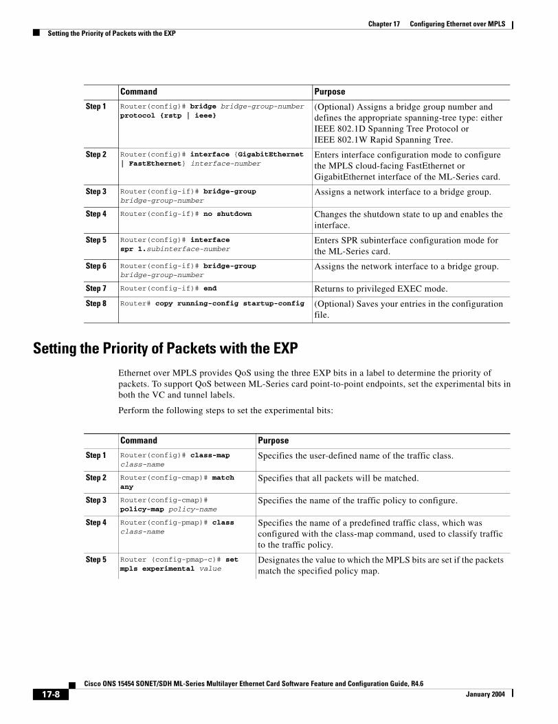
Chapter 17 Configuring Ethernet over MPLSSetting the Priority of Packets with the EXP
Setting the Priority of Packets with the EXPEthernet over MPLS provides QoS using the three EXP bits in a label to determine the priority of packets. To support QoS between ML-Series card point-to-point endpoints, set the experimental bits in both the VC and tunnel labels.
Perform the following steps to set the experimental bits:
Command Purpose
Step 1 Router(config)# bridge bridge-group-number protocol {rstp | ieee}
(Optional) Assigns a bridge group number and defines the appropriate spanning-tree type: either IEEE 802.1D Spanning Tree Protocol or IEEE 802.1W Rapid Spanning Tree.
Step 2 Router(config)# interface {GigabitEthernet | FastEthernet} interface-number
Enters interface configuration mode to configure the MPLS cloud-facing FastEthernet or GigabitEthernet interface of the ML-Series card.
Step 3 Router(config-if)# bridge-group bridge-group-number
Assigns a network interface to a bridge group.
Step 4 Router(config-if)# no shutdown Changes the shutdown state to up and enables the interface.
Step 5 Router(config)# interface spr 1.subinterface-number
Enters SPR subinterface configuration mode for the ML-Series card.
Step 6 Router(config-if)# bridge-group bridge-group-number
Assigns the network interface to a bridge group.
Step 7 Router(config-if)# end Returns to privileged EXEC mode.
Step 8 Router# copy running-config startup-config (Optional) Saves your entries in the configuration file.
Command Purpose
Step 1 Router(config)# class-map class-name
Specifies the user-defined name of the traffic class.
Step 2 Router(config-cmap)# match any
Specifies that all packets will be matched.
Step 3 Router(config-cmap)# policy-map policy-name
Specifies the name of the traffic policy to configure.
Step 4 Router(config-pmap)# class class-name
Specifies the name of a predefined traffic class, which was configured with the class-map command, used to classify traffic to the traffic policy.
Step 5 Router (config-pmap-c)# set mpls experimental value
Designates the value to which the MPLS bits are set if the packets match the specified policy map.
17-8Cisco ONS 15454 SONET/SDH ML-Series Multilayer Ethernet Card Software Feature and Configuration Guide, R4.6
January 2004
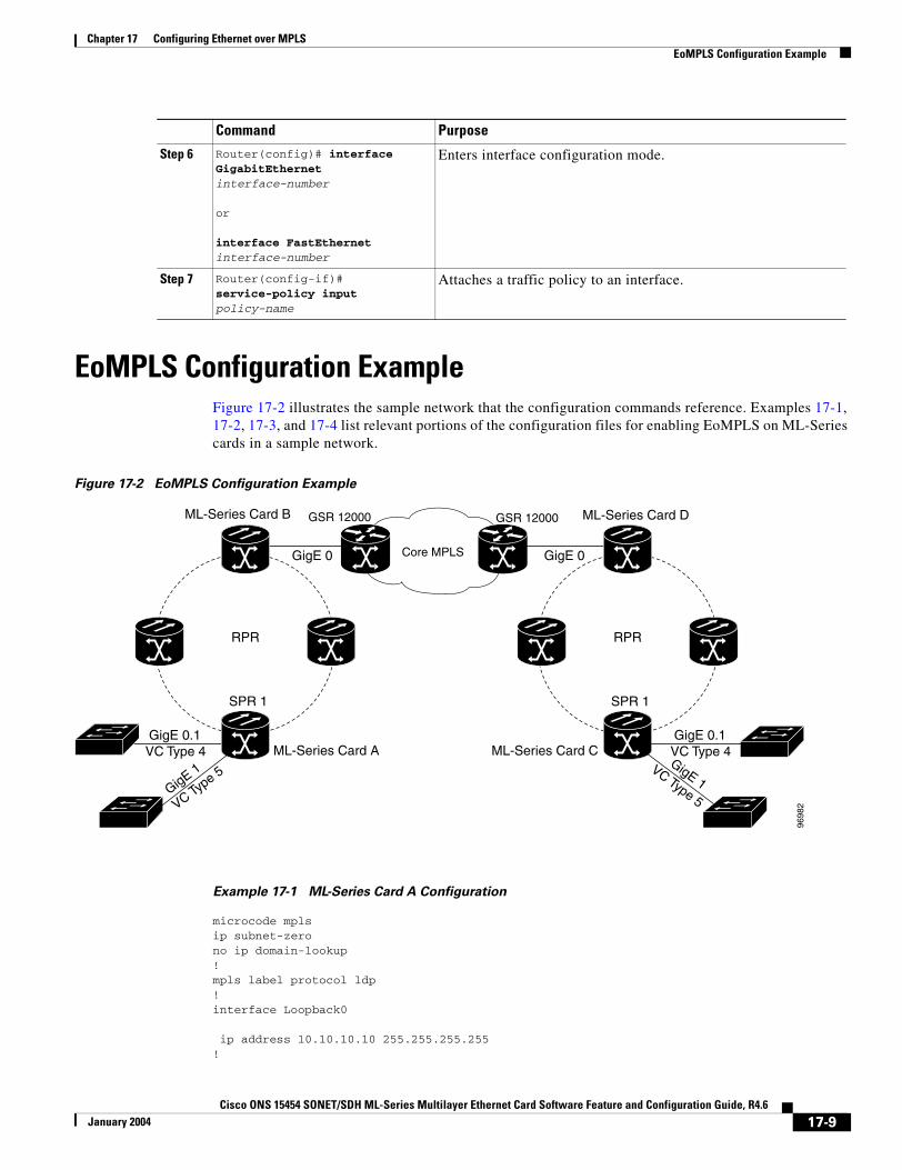
Chapter 17 Configuring Ethernet over MPLSEoMPLS Configuration Example
EoMPLS Configuration ExampleFigure 17-2 illustrates the sample network that the configuration commands reference. Examples 17-1, 17-2, 17-3, and 17-4 list relevant portions of the configuration files for enabling EoMPLS on ML-Series cards in a sample network.
Figure 17-2 EoMPLS Configuration Example
Example 17-1 ML-Series Card A Configuration
microcode mplsip subnet-zerono ip domain-lookup!mpls label protocol ldp!interface Loopback0
ip address 10.10.10.10 255.255.255.255!
Step 6 Router(config)# interface GigabitEthernet interface-number
or
interface FastEthernet interface-number
Enters interface configuration mode.
Step 7 Router(config-if)# service-policy input policy-name
Attaches a traffic policy to an interface.
Command Purpose
Core MPLS
RPR RPR
GigE 0.1VC Type 4
SPR 1
GSR 12000
GigE 0
ML-Series Card A
ML-Series Card B
ML-Series Card C
ML-Series Card D
GigE 0
GigE 0.1VC Type 4
SPR 1
GigE 1
VC Type 5
GigE 1VC Type 5
GSR 12000
9698
2
17-9Cisco ONS 15454 SONET/SDH ML-Series Multilayer Ethernet Card Software Feature and Configuration Guide, R4.6
January 2004
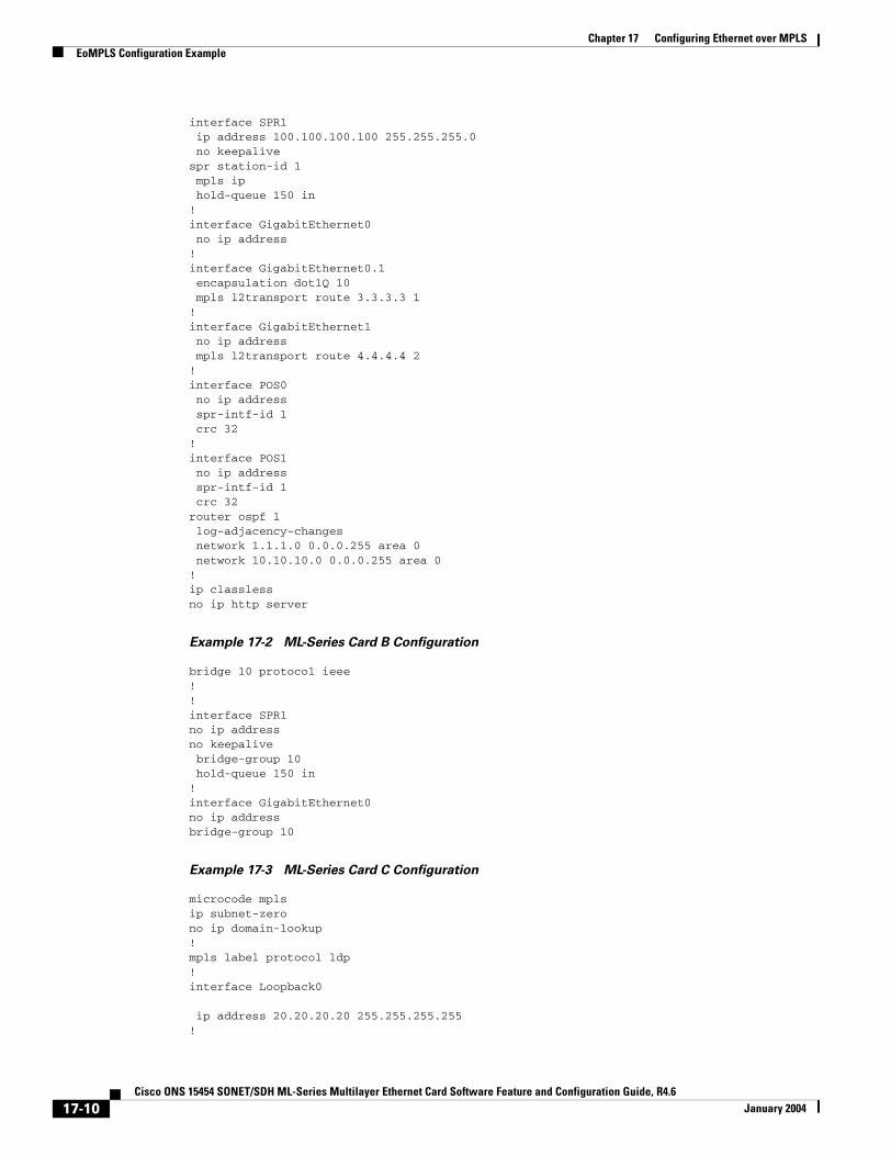
Chapter 17 Configuring Ethernet over MPLSEoMPLS Configuration Example
interface SPR1 ip address 100.100.100.100 255.255.255.0 no keepalivespr station-id 1 mpls ip hold-queue 150 in!interface GigabitEthernet0 no ip address!interface GigabitEthernet0.1 encapsulation dot1Q 10 mpls l2transport route 3.3.3.3 1 !interface GigabitEthernet1 no ip address mpls l2transport route 4.4.4.4 2 !interface POS0 no ip address spr-intf-id 1 crc 32!interface POS1 no ip address spr-intf-id 1 crc 32router ospf 1 log-adjacency-changes network 1.1.1.0 0.0.0.255 area 0 network 10.10.10.0 0.0.0.255 area 0!ip classlessno ip http server
Example 17-2 ML-Series Card B Configuration
bridge 10 protocol ieee!!interface SPR1no ip addressno keepalive bridge-group 10 hold-queue 150 in!interface GigabitEthernet0no ip addressbridge-group 10
Example 17-3 ML-Series Card C Configuration
microcode mplsip subnet-zerono ip domain-lookup!mpls label protocol ldp!interface Loopback0
ip address 20.20.20.20 255.255.255.255!
17-10Cisco ONS 15454 SONET/SDH ML-Series Multilayer Ethernet Card Software Feature and Configuration Guide, R4.6
January 2004
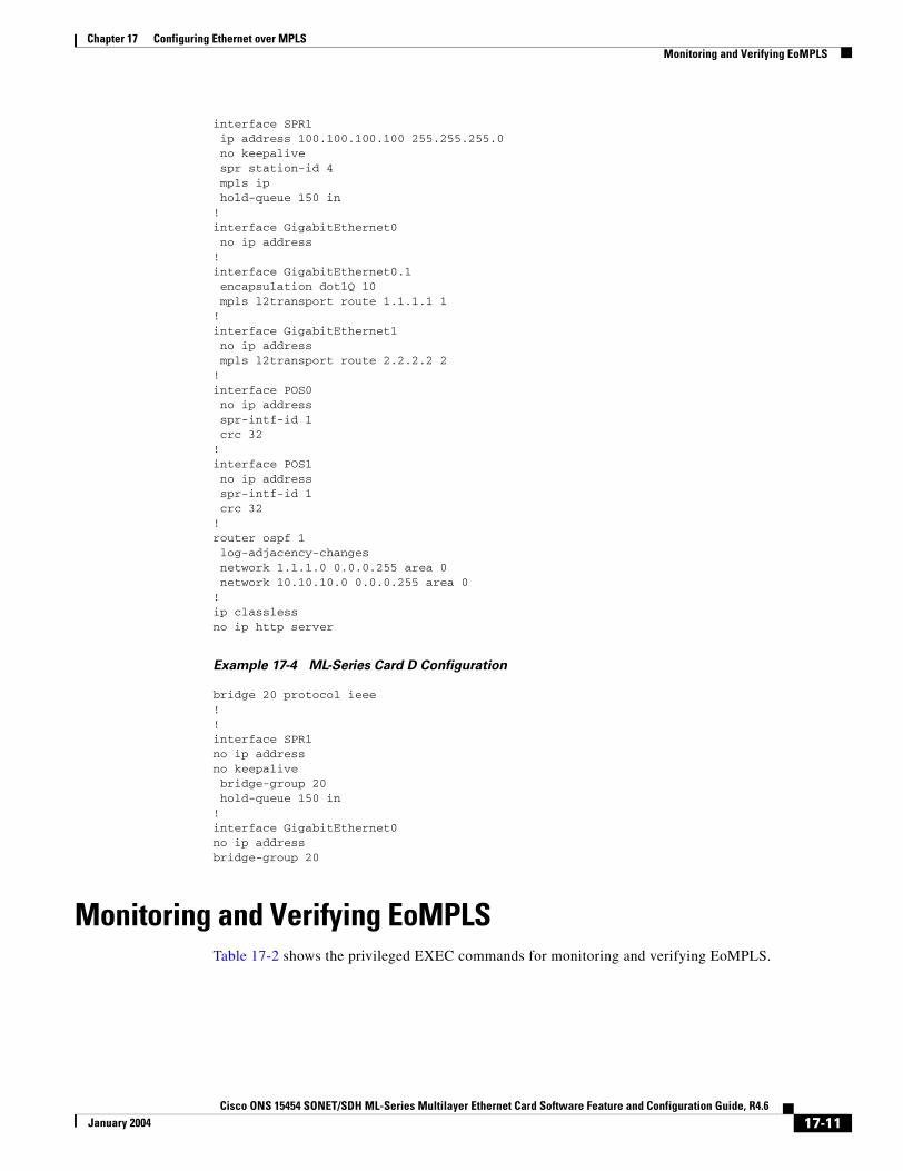
Chapter 17 Configuring Ethernet over MPLSMonitoring and Verifying EoMPLS
interface SPR1 ip address 100.100.100.100 255.255.255.0 no keepalive spr station-id 4 mpls ip hold-queue 150 in!interface GigabitEthernet0 no ip address!interface GigabitEthernet0.1 encapsulation dot1Q 10 mpls l2transport route 1.1.1.1 1 !interface GigabitEthernet1 no ip address mpls l2transport route 2.2.2.2 2 !interface POS0 no ip address spr-intf-id 1 crc 32!interface POS1 no ip address spr-intf-id 1 crc 32!router ospf 1 log-adjacency-changes network 1.1.1.0 0.0.0.255 area 0 network 10.10.10.0 0.0.0.255 area 0!ip classlessno ip http server
Example 17-4 ML-Series Card D Configuration
bridge 20 protocol ieee!!interface SPR1no ip addressno keepalive bridge-group 20 hold-queue 150 in!interface GigabitEthernet0no ip addressbridge-group 20
Monitoring and Verifying EoMPLSTable 17-2 shows the privileged EXEC commands for monitoring and verifying EoMPLS.
17-11Cisco ONS 15454 SONET/SDH ML-Series Multilayer Ethernet Card Software Feature and Configuration Guide, R4.6
January 2004
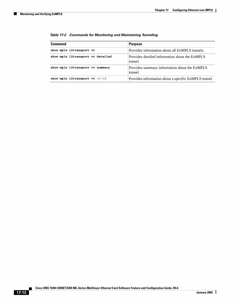
Chapter 17 Configuring Ethernet over MPLSMonitoring and Verifying EoMPLS
Table 17-2 Commands for Monitoring and Maintaining Tunneling
Command Purpose
show mpls l2transport vc Provides information about all EoMPLS tunnels.show mpls l2transport vc detailed Provides detailed information about the EoMPLS
tunnel.show mpls l2transport vc summary Provides summary information about the EoMPLS
tunnel.show mpls l2transport vc vc-id Provides information about a specific EoMPLS tunnel.
17-12Cisco ONS 15454 SONET/SDH ML-Series Multilayer Ethernet Card Software Feature and Configuration Guide, R4.6
January 2004
Cisco ONS 15454 SONET/SDH ML-Series Multilayer Ethernet Card SoftwarJanuary 2004
A P P E N D I X A
Command ReferenceNote The terms "Unidirectional Path Switched Ring" and "UPSR" may appear in Cisco literature. These terms do not refer to using Cisco ONS 15xxx products in a unidirectional path switched ring configuration. Rather, these terms, as well as "Path Protected Mesh Network" and "PPMN," refer generally to Cisco's path protection feature, which may be used in any topological network configuration. Cisco does not recommend using its path protection feature in any particular topological network configuration.
This appendix provides a command reference for those Cisco IOS commands or those aspects of Cisco IOS commands unique to ML-Series cards. For information about the standard Cisco IOS Release 12.1 commands, refer to the Cisco IOS documentation set available from the Cisco.com home page. Use the Select an Area pull-down menu to select Products and Services > Technical Documentation. On the Cisco Product Documentation home page, select Release 12.1 from the Cisco IOS Software drop-down list.
A-1e Feature and Configuration Guide, R4.6

Appendix A Command Reference[no] bridge bridge-group-number protocol {drpri-rstp | ieee | rstp}
[no] bridge bridge-group-number protocol {drpri-rstp | ieee | rstp}To define the protocol employed by a bridge-group, use the bridge protocol global configuration command. If no protocol will be employed by the bridge-group, this command is not needed. To remove a protocol from the bridge group, use the no form of this command with the appropriate keywords and arguments.
Syntax Description
Defaults N/A
Command Modes Global configuration
Usage Guidelines The protocol DRPRI-RSTP is only employed when configuring ML-Series cards as part of a DRPRI. A bridge group with DRPRI is limited to one protocol, so the bridge group cannot also implement rapid spanning tree protocol (RSTP) or spanning tree protocol (STP).
Examples The following example assigns the DRPRI protocol to the bridge group with the bridge group number of 100.
Router(config)# bridge 100 protocol drpri-rstp
Parameter Description
drpri-rstp The protocol that enables the Dual RPR Interconnect (DRPRI) feature of the ML-Series cards.
ieee IEEE 802.1D Spanning Tree Protocol.rstp IEEE 802.1W Rapid Spanning Tree Protocol.bridge-group-number The identifying number of the bridge group being assigned a protocol.
A-2Cisco ONS 15454 SONET/SDH ML-Series Multilayer Ethernet Card Software Feature and Configuration Guide, R4.6
January 2004
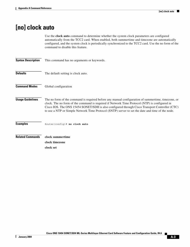
Appendix A Command Reference[no] clock auto
[no] clock autoUse the clock auto command to determine whether the system clock parameters are configured automatically from the TCC2 card. When enabled, both summertime and timezone are automatically configured, and the system clock is periodically synchronized to the TCC2 card. Use the no form of the command to disable this feature.
Syntax Description This command has no arguments or keywords.
Defaults The default setting is clock auto.
Command Modes Global configuration
Usage Guidelines The no form of the command is required before any manual configuration of summertime, timezone, or clock. The no form of the command is required if Network Time Protocol (NTP) is configured in Cisco IOS. The ONS 15454 SONET/SDH is also configured through Cisco Transport Controller (CTC) to use a NTP or Simple Network Time Protocol (SNTP) server to set the date and time of the node.
Examples Router(config)# no clock auto
Related Commands clock summertime
clock timezone
clock set
A-3Cisco ONS 15454 SONET/SDH ML-Series Multilayer Ethernet Card Software Feature and Configuration Guide, R4.6
January 2004
Appendix A Command Referenceinterface spr 1
interface spr 1Use this command to create a shared packet ring (spr) interface on an ML-Series card for a resilient packet ring (RPR). If the interface has already been created, this command enters spr interface configuration mode. The only valid spr interface number is 1.
Defaults N/A
Command Modes Global configuration
Usage Guidelines The command allows the user to create a virtual interface for the RPR/SPR. Commands such as spr wrap or spr station-id can then be applied to the RPR through SPR configuration command mode.
Examples The following example creates the shared packet ring interface: Router(config)# interface spr 1
Related Commands spr drpri-id
spr-intf-id
spr station-id
spr wrap
A-4Cisco ONS 15454 SONET/SDH ML-Series Multilayer Ethernet Card Software Feature and Configuration Guide, R4.6
January 2004

Appendix A Command Reference[no] pos flag c2 value
[no] pos flag c2 value Use this command to specify the C2 byte value for transmitted and received frames. Use the no form of the command to return the C2 byte to it’s default value.
Syntax Description
Defaults When changing the encapsulation on a Packet over SONET/SDH (POS) port between LEX and Point-to-Point Protocol/high-level data link control (PPP/HDLC), the scrambling and c2 settings are automatically changed to their default values according to Table A-1.
In PPP/HDLC encapsulation, changing the scrambling, automatically changes the “pos flag c2” to its default according to Table A-2. In LEX encapsulation, changing the scrambling does not affect c2.
Command Modes Interface configuration mode (packet over SONET [POS] only)
Usage Guidelines This value is normally configured to match the setting on the peer path terminating equipment (PTE). Using the correct order of operations will avoid having the nondefault settings overridden by the encapsulation change. The recommended order follows:
1. Set encap to PPP/HDLC
2. Set scrambling (if a nondefault setting is required)
3. Set c2 (if a nondefault setting is required)
Also note that the cyclic redundandy check (CRC) setting varies among different types of PTE. The default CRC on the ML-Series card is 32-bits, regardless of any other settings. In most circumstances, the default settings should be correct, but users need to verify this with the user documentation for the PTE.
Parameter Description
value C2 byte value
Table A-1 Scrambling and c2 Default Values
encap scrambling c2
LEX pos scramble-spe pos flag c2 0x01
PPP/HDLC no pos scramble-spe pos flag c2 0xCF
Table A-2 pos flag c2 Default Values
encap scrambling c2
PPP/HDLC pos scramble-spe pos flag c2 0xCF
PPP/HDLC no pos scramble-spe pos flag c2 0x16
A-5Cisco ONS 15454 SONET/SDH ML-Series Multilayer Ethernet Card Software Feature and Configuration Guide, R4.6
January 2004

Appendix A Command Reference[no] pos flag c2 value
Examples Gateway(config)# int pos0Gateway(config-if)# pos flag c2 0x16
Related Commands pos trigger defects
pos report
A-6Cisco ONS 15454 SONET/SDH ML-Series Multilayer Ethernet Card Software Feature and Configuration Guide, R4.6
January 2004
Appendix A Command Reference[no] pos pdi holdoff time
[no] pos pdi holdoff timeUse this command to specify the time, in milliseconds, to holdoff sending the path defect indication (PDI) to the far-end when a VCAT member circuit is added to the virtual concatenation group (VCG). Use the no form of the command to use the default value.
Syntax Description
Defaults The default value is 100 milliseconds.
Command Modes Interface configuration mode (POS only)
Usage Guidelines This value is normally configured to match the setting on the peer PTE. The time granularity for this command is 1 milliseconds.
Examples Gateway(config)# int pos0Gateway(config-if)# pos pdi holdoff 500
Related Commands pos trigger defects
Parameter Description
time delay time in milliseconds, 100 to 1000
A-7Cisco ONS 15454 SONET/SDH ML-Series Multilayer Ethernet Card Software Feature and Configuration Guide, R4.6
January 2004
Appendix A Command Reference[no] pos report alarm
[no] pos report alarm Use this command to specify which alarms/signals are logged to the console. This command has no effect on whether alarms are reported to the TCC2/TCC2P and CTC. These conditions are soaked and cleared per Telcordia GR-253. Use the no form of the command to disable reporting of a specific alarm/signal.
Syntax Description
Defaults The default is to report all alarms.
Command Modes Interface configuration mode (POS only)
Usage Guidelines This value is normally configured to match the setting on the peer PTE.
Examples Gateway(config)# int pos0Gateway(config-if)# pos report allGateway(config-if)# pos flag c2 103:16:51: %SONET-4-ALARM: POS0: PPLM Gateway(config-if)# pos flag c2 0x1603:17:34: %SONET-4-ALARM: POS0: PPLM cleared
Related Commands pos trigger defects
Parameter Description
alarm The SONET/SDH alarm that is logged to the console. The alarms are as follows:
all—All link down alarm failures
ber_sd_b3—PBIP BER in excess of SD threshold failure
ber_sf_b3—PBIP BER in excess of SD threshold failure
encap—Path Signal Label Encapsulation Mismatch failure
pais—Path Alarm Indication Signal failure
plop—Path Loss of Pointer failure
ppdi—Path Payload Defect Indication failure
pplm—Payload label mismatch path
prdi—Path Remote Defect Indication failure
ptim—Path Trace Indicator Mismatch failure
puneq—Path Label Equivalent to Zero failure
A-8Cisco ONS 15454 SONET/SDH ML-Series Multilayer Ethernet Card Software Feature and Configuration Guide, R4.6
January 2004
Appendix A Command Reference[non] pos trigger defects condition
[non] pos trigger defects condition Use this command to specify which conditions cause the associated POS link state to change. These conditions are soaked/cleared using the delay specified in the pos trigger delay command. Use the no form of the command to disable triggering on a specific condition.
Syntax Description
Defaults See list in above description.
Command Modes Interface configuration mode (POS only)
Usage Guidelines This value is normally configured to match the setting on the peer PTE.
Examples Gateway(config)# int pos0Gateway(config-if)# pos trigger defects all
Related Commands pos trigger delay
Parameter Description
condition The SONET/SDH condition that causes the link state change. The conditions are as follows:
all—All link down alarm failures
ber_sd_b3—PBIP BER in excess of SD threshold failure
ber_sf_b3—PBIP BER in excess of SD threshold failure (default)
encap—Path Signal Label Encapsulation Mismatch failure (default)
pais—Path Alarm Indication Signal failure (default)
plop—Path Loss of Pointer failure (default)
ppdi—Path Payload Defect Indication failure (default)
pplm—Payload label mismatch path (default)
prdi—Path Remote Defect Indication failure (default)
ptim—Path Trace Indicator Mismatch failure (default)
puneq—Path Label Equivalent to Zero failure (default)
A-9Cisco ONS 15454 SONET/SDH ML-Series Multilayer Ethernet Card Software Feature and Configuration Guide, R4.6
January 2004
Appendix A Command Reference[no] pos trigger delay time
[no] pos trigger delay time Use this command to specify which conditions cause the associated POS link state to change. The conditions specified in the pos trigger defects command are soaked/cleared using this delay. Use the no form of the command to use the default value.
Syntax Description
Defaults The default value is 200 milliseconds.
Command Modes Interface configuration mode (POS only)
Usage Guidelines This value is normally configured to match the setting on the peer PTE. The time granularity for this command is 50 milliseconds.
Examples Gateway(config)# int pos0Gateway(config-if)# pos trigger delay 500
Related Commands pos trigger defects
Parameter Description
time delay time in milliseconds, 200 to 2000
A-10Cisco ONS 15454 SONET/SDH ML-Series Multilayer Ethernet Card Software Feature and Configuration Guide, R4.6
January 2004
Appendix A Command Reference[no] pos scramble-spe
[no] pos scramble-speUse this command to enable scrambling.
Syntax Description This command has no arguments or keywords.
Defaults The default value depends on the encapsulation.
Command Modes Interface configuration mode (POS only)
Usage Guidelines This value is normally configured to match the setting on the peer PTE. This command might change the pos flag c2 configuration.
Examples Gateway(config)# int pos0Gateway(config-if)# pos scramble-spe
Related Commands pos flag c2
encap scrambling
LEX pos scramble-spe
PPP/HDLC no pos scramble-spe
A-11Cisco ONS 15454 SONET/SDH ML-Series Multilayer Ethernet Card Software Feature and Configuration Guide, R4.6
January 2004
Appendix A Command Reference[no] pos vcat defect {immediate | delayed}
[no] pos vcat defect {immediate | delayed}Sets the VCAT defect processing mode to either handle a defects state change the instant it is detected or wait for the time specified by pos trigger delay. Use the no form of the command to use the default value.
Syntax Description
Defaults The default setting is immediate.
Command Modes POS interface configuration
Usage Guidelines Immediate should be used if the VCAT circuit uses unprotected SONET circuits. Delayed should be runif the VCAT circuit uses SONET protected circuits (bidirectional line switch ring [BLSR] or path protection.
Examples The following example sets an ML-Series card to delayed:Router(config)# interface pos 1Router(config-if)# pos vcat defect delayed
Related Commands interface spr 1spr wrapinterface pos 1pos trigger delay
Parameter Description
immediate Handles a defect state change the instant it is detected.delayed Handles the defect after the time specified by the command pos trigger delay.
If delay is configured and the circuit is on RPR, then the RPR defect processing will also be delayed by the delay time.
A-12Cisco ONS 15454 SONET/SDH ML-Series Multilayer Ethernet Card Software Feature and Configuration Guide, R4.6
January 2004

Appendix A Command Referenceshow controller pos interface-number [details]
show controller pos interface-number [details]Use this command to display the status of the POS controller. Use the details argument to obtain certain additional information.
Syntax Description
Defaults N/A
Command Modes Privileged EXEC
Usage Guidelines This command can be used to help diagnose and isolate POS or SONET problems.
Examples
Continuous Concatenation Circuit (CCAT) Show Controller Output Example
Router# show controller pos 0Interface POS0Hardware is Packet/Ethernet over Sonet Concatenation: CCAT Circuit state: IS PATH PAIS = 0 PLOP = 0 PRDI = 0 PTIM = 0 PPLM = 0 PUNEQ = 0 PPDI = 0 PTIU = 0 BER_SF_B3 = 0 BER_SD_B3 = 0 BIP(B3) = 20 REI = 2 NEWPTR = 0 PSE = 0 NSE = 0
Active Alarms : NoneDemoted Alarms: NoneActive Defects: NoneAlarms reportable to CLI: PAIS PLOP PUNEQ PTIM PPLM PRDI PPDI BER_SF_B3 BER_SD_B3 VCAT_OOU_TPT LOM SQM Link state change defects: PAIS PLOP PUNEQ PTIM PPLM PRDI PPDI BER_SF_B3 Link state change time : 200 (msec)
DOS FPGA channel number : 0Starting STS (0 based) : 0VT ID (if any) (0 based) : 255Circuit size : VC4RDI Mode : 1 bitC2 (tx / rx) : 0x01 / 0x01Framing : SDH
Path Trace Mode : off Transmit String : Expected String : Received String :
Parameter Description
interface-number Number of the POS interface (0–1)
A-13Cisco ONS 15454 SONET/SDH ML-Series Multilayer Ethernet Card Software Feature and Configuration Guide, R4.6
January 2004
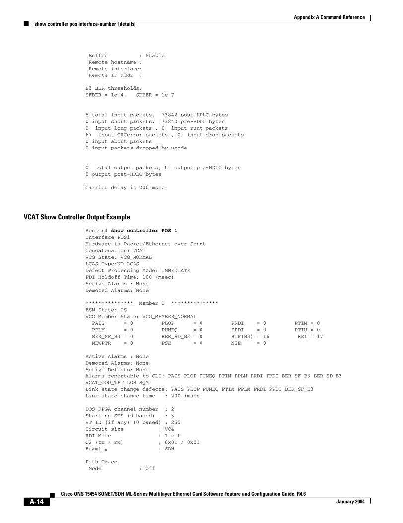
Appendix A Command Referenceshow controller pos interface-number [details]
Buffer : Stable Remote hostname : Remote interface: Remote IP addr :
B3 BER thresholds: SFBER = 1e-4, SDBER = 1e-7
5 total input packets, 73842 post-HDLC bytes0 input short packets, 73842 pre-HDLC bytes0 input long packets , 0 input runt packets67 input CRCerror packets , 0 input drop packets0 input abort packets0 input packets dropped by ucode
0 total output packets, 0 output pre-HDLC bytes0 output post-HDLC bytes
Carrier delay is 200 msec
VCAT Show Controller Output Example
Router# show controller POS 1Interface POS1Hardware is Packet/Ethernet over Sonet Concatenation: VCAT VCG State: VCG_NORMAL LCAS Type:NO LCAS Defect Processing Mode: IMMEDIATE PDI Holdoff Time: 100 (msec) Active Alarms : NoneDemoted Alarms: None
*************** Member 1 ***************ESM State: IS VCG Member State: VCG_MEMBER_NORMAL PAIS = 0 PLOP = 0 PRDI = 0 PTIM = 0 PPLM = 0 PUNEQ = 0 PPDI = 0 PTIU = 0 BER_SF_B3 = 0 BER_SD_B3 = 0 BIP(B3) = 16 REI = 17 NEWPTR = 0 PSE = 0 NSE = 0
Active Alarms : NoneDemoted Alarms: NoneActive Defects: NoneAlarms reportable to CLI: PAIS PLOP PUNEQ PTIM PPLM PRDI PPDI BER_SF_B3 BER_SD_B3 VCAT_OOU_TPT LOM SQM Link state change defects: PAIS PLOP PUNEQ PTIM PPLM PRDI PPDI BER_SF_B3 Link state change time : 200 (msec)
DOS FPGA channel number : 2Starting STS (0 based) : 3VT ID (if any) (0 based) : 255Circuit size : VC4RDI Mode : 1 bitC2 (tx / rx) : 0x01 / 0x01Framing : SDH
Path Trace Mode : off
A-14Cisco ONS 15454 SONET/SDH ML-Series Multilayer Ethernet Card Software Feature and Configuration Guide, R4.6
January 2004
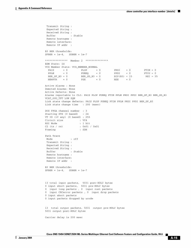
Appendix A Command Referenceshow controller pos interface-number [details]
Transmit String : Expected String : Received String : Buffer : Stable Remote hostname : Remote interface: Remote IP addr :
B3 BER thresholds: SFBER = 1e-4, SDBER = 1e-7 *************** Member 2 ***************ESM State: IS VCG Member State: VCG_MEMBER_NORMAL PAIS = 0 PLOP = 0 PRDI = 0 PTIM = 0 PPLM = 0 PUNEQ = 0 PPDI = 0 PTIU = 0 BER_SF_B3 = 0 BER_SD_B3 = 0 BIP(B3) = 15 REI = 35 NEWPTR = 0 PSE = 0 NSE = 0
Active Alarms : NoneDemoted Alarms: NoneActive Defects: NoneAlarms reportable to CLI: PAIS PLOP PUNEQ PTIM PPLM PRDI PPDI BER_SF_B3 BER_SD_B3 VCAT_OOU_TPT LOM SQM Link state change defects: PAIS PLOP PUNEQ PTIM PPLM PRDI PPDI BER_SF_B3 Link state change time : 200 (msec)
DOS FPGA channel number : 3Starting STS (0 based) : 24VT ID (if any) (0 based) : 255Circuit size : VC4RDI Mode : 1 bitC2 (tx / rx) : 0x01 / 0x01Framing : SDH
Path Trace Mode : off Transmit String : Expected String : Received String : Buffer : Stable Remote hostname : Remote interface: Remote IP addr :
B3 BER thresholds: SFBER = 1e-4, SDBER = 1e-7
13 total input packets, 5031 post-HDLC bytes0 input short packets, 5031 pre-HDLC bytes0 input long packets , 0 input runt packets0 input CRCerror packets , 0 input drop packets0 input abort packets0 input packets dropped by ucode
13 total output packets, 5031 output pre-HDLC bytes5031 output post-HDLC bytes
Carrier delay is 200 msec
A-15Cisco ONS 15454 SONET/SDH ML-Series Multilayer Ethernet Card Software Feature and Configuration Guide, R4.6
January 2004

Appendix A Command Referenceshow controller pos interface-number [details]
Related Commands show interface pos
clear counters
A-16Cisco ONS 15454 SONET/SDH ML-Series Multilayer Ethernet Card Software Feature and Configuration Guide, R4.6
January 2004
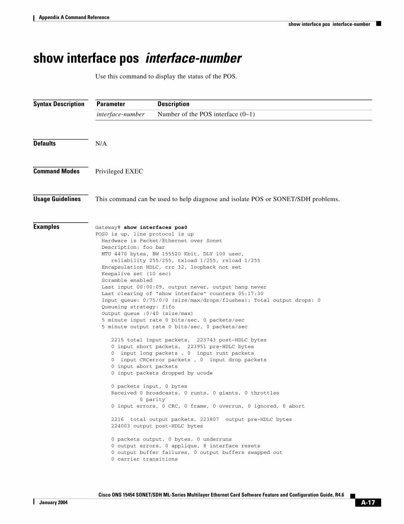
Appendix A Command Referenceshow interface pos interface-number
show interface pos interface-number Use this command to display the status of the POS.
Syntax Description
Defaults N/A
Command Modes Privileged EXEC
Usage Guidelines This command can be used to help diagnose and isolate POS or SONET/SDH problems.
Examples Gateway# show interfaces pos0POS0 is up, line protocol is up Hardware is Packet/Ethernet over Sonet Description: foo bar MTU 4470 bytes, BW 155520 Kbit, DLY 100 usec, reliability 255/255, txload 1/255, rxload 1/255 Encapsulation HDLC, crc 32, loopback not set Keepalive set (10 sec) Scramble enabled Last input 00:00:09, output never, output hang never Last clearing of "show interface" counters 05:17:30 Input queue: 0/75/0/0 (size/max/drops/flushes); Total output drops: 0 Queueing strategy: fifo Output queue :0/40 (size/max) 5 minute input rate 0 bits/sec, 0 packets/sec 5 minute output rate 0 bits/sec, 0 packets/sec
2215 total input packets, 223743 post-HDLC bytes 0 input short packets, 223951 pre-HDLC bytes 0 input long packets , 0 input runt packets 0 input CRCerror packets , 0 input drop packets 0 input abort packets 0 input packets dropped by ucode
0 packets input, 0 bytes Received 0 broadcasts, 0 runts, 0 giants, 0 throttles 0 parity 0 input errors, 0 CRC, 0 frame, 0 overrun, 0 ignored, 0 abort
2216 total output packets, 223807 output pre-HDLC bytes 224003 output post-HDLC bytes
0 packets output, 0 bytes, 0 underruns 0 output errors, 0 applique, 8 interface resets 0 output buffer failures, 0 output buffers swapped out 0 carrier transitions
Parameter Description
interface-number Number of the POS interface (0–1)
A-17Cisco ONS 15454 SONET/SDH ML-Series Multilayer Ethernet Card Software Feature and Configuration Guide, R4.6
January 2004

Appendix A Command Referenceshow interface pos interface-number
Related Commands show controller pos
clear counters
A-18Cisco ONS 15454 SONET/SDH ML-Series Multilayer Ethernet Card Software Feature and Configuration Guide, R4.6
January 2004
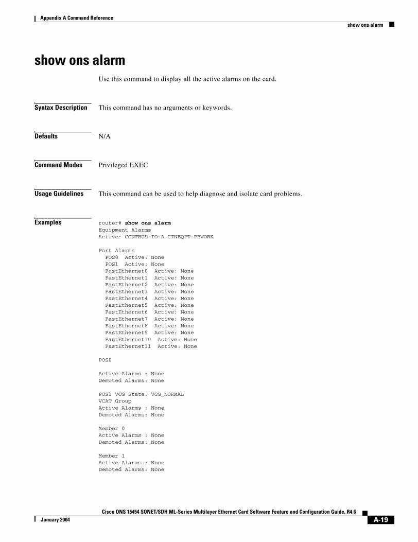
Appendix A Command Referenceshow ons alarm
show ons alarm Use this command to display all the active alarms on the card.
Syntax Description This command has no arguments or keywords.
Defaults N/A
Command Modes Privileged EXEC
Usage Guidelines This command can be used to help diagnose and isolate card problems.
Examples router# show ons alarmEquipment AlarmsActive: CONTBUS-IO-A CTNEQPT-PBWORK
Port Alarms POS0 Active: None POS1 Active: None FastEthernet0 Active: None FastEthernet1 Active: None FastEthernet2 Active: None FastEthernet3 Active: None FastEthernet4 Active: None FastEthernet5 Active: None FastEthernet6 Active: None FastEthernet7 Active: None FastEthernet8 Active: None FastEthernet9 Active: None FastEthernet10 Active: None FastEthernet11 Active: None
POS0
Active Alarms : NoneDemoted Alarms: None
POS1 VCG State: VCG_NORMALVCAT GroupActive Alarms : NoneDemoted Alarms: None
Member 0Active Alarms : NoneDemoted Alarms: None
Member 1Active Alarms : NoneDemoted Alarms: None
A-19Cisco ONS 15454 SONET/SDH ML-Series Multilayer Ethernet Card Software Feature and Configuration Guide, R4.6
January 2004

Appendix A Command Referenceshow ons alarm
Related Commands show controller pos
show ons alarm defects
show ons alarm failures
A-20Cisco ONS 15454 SONET/SDH ML-Series Multilayer Ethernet Card Software Feature and Configuration Guide, R4.6
January 2004
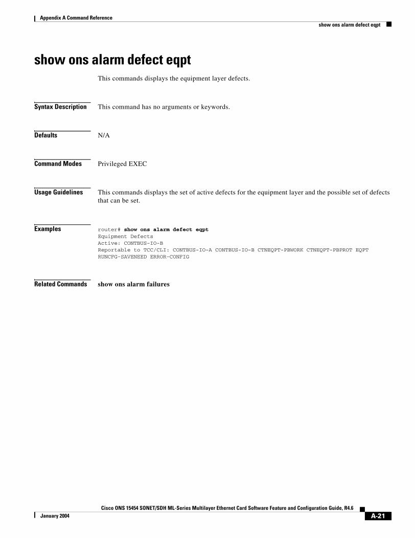
Appendix A Command Referenceshow ons alarm defect eqpt
show ons alarm defect eqptThis commands displays the equipment layer defects.
Syntax Description This command has no arguments or keywords.
Defaults N/A
Command Modes Privileged EXEC
Usage Guidelines This commands displays the set of active defects for the equipment layer and the possible set of defects that can be set.
Examples router# show ons alarm defect eqptEquipment DefectsActive: CONTBUS-IO-BReportable to TCC/CLI: CONTBUS-IO-A CONTBUS-IO-B CTNEQPT-PBWORK CTNEQPT-PBPROT EQPT RUNCFG-SAVENEED ERROR-CONFIG
Related Commands show ons alarm failures
A-21Cisco ONS 15454 SONET/SDH ML-Series Multilayer Ethernet Card Software Feature and Configuration Guide, R4.6
January 2004
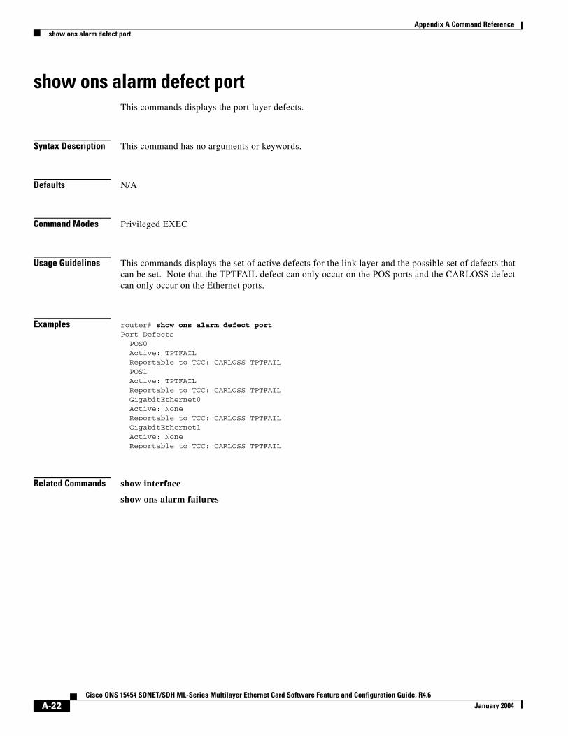
Appendix A Command Referenceshow ons alarm defect port
show ons alarm defect portThis commands displays the port layer defects.
Syntax Description This command has no arguments or keywords.
Defaults N/A
Command Modes Privileged EXEC
Usage Guidelines This commands displays the set of active defects for the link layer and the possible set of defects that can be set. Note that the TPTFAIL defect can only occur on the POS ports and the CARLOSS defect can only occur on the Ethernet ports.
Examples router# show ons alarm defect portPort Defects POS0 Active: TPTFAIL Reportable to TCC: CARLOSS TPTFAIL POS1 Active: TPTFAIL Reportable to TCC: CARLOSS TPTFAIL GigabitEthernet0 Active: None Reportable to TCC: CARLOSS TPTFAIL GigabitEthernet1 Active: None Reportable to TCC: CARLOSS TPTFAIL
Related Commands show interface
show ons alarm failures
A-22Cisco ONS 15454 SONET/SDH ML-Series Multilayer Ethernet Card Software Feature and Configuration Guide, R4.6
January 2004
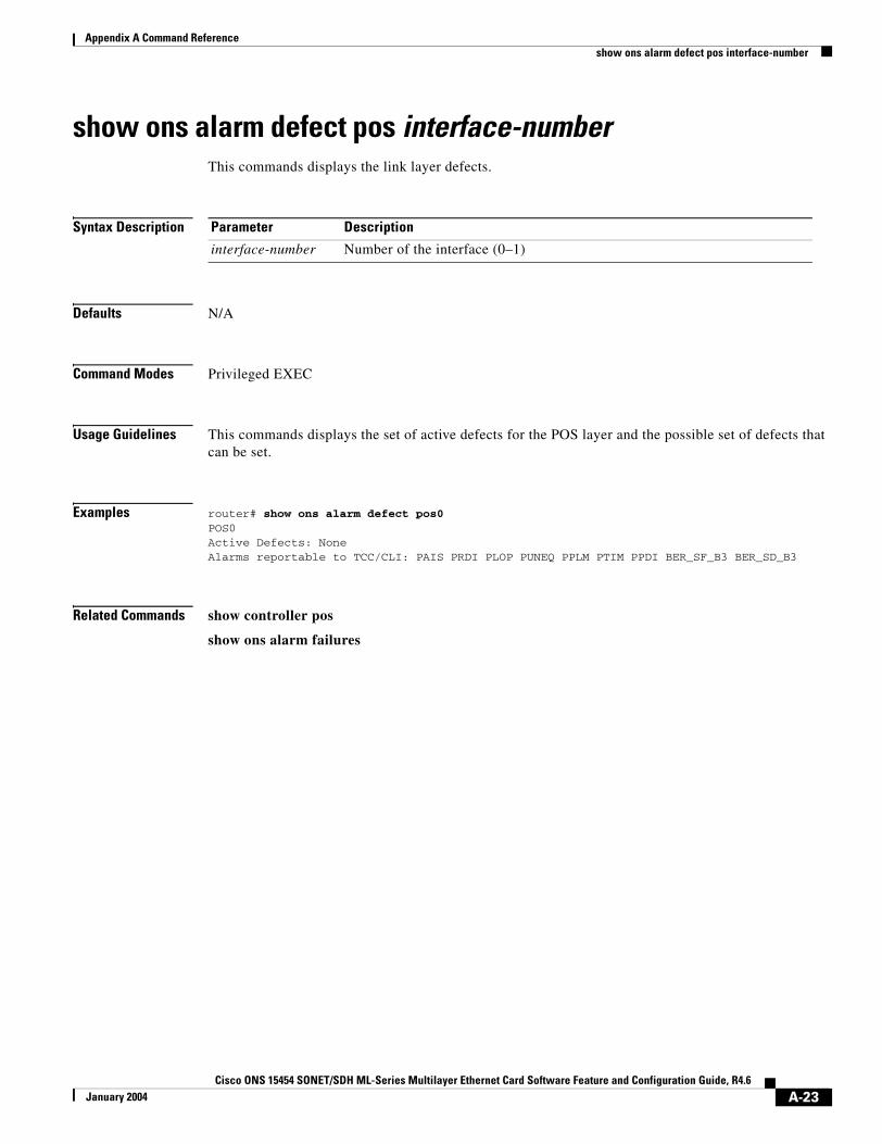
Appendix A Command Referenceshow ons alarm defect pos interface-number
show ons alarm defect pos interface-number This commands displays the link layer defects.
Syntax Description
Defaults N/A
Command Modes Privileged EXEC
Usage Guidelines This commands displays the set of active defects for the POS layer and the possible set of defects that can be set.
Examples router# show ons alarm defect pos0POS0Active Defects: NoneAlarms reportable to TCC/CLI: PAIS PRDI PLOP PUNEQ PPLM PTIM PPDI BER_SF_B3 BER_SD_B3
Related Commands show controller pos
show ons alarm failures
Parameter Description
interface-number Number of the interface (0–1)
A-23Cisco ONS 15454 SONET/SDH ML-Series Multilayer Ethernet Card Software Feature and Configuration Guide, R4.6
January 2004
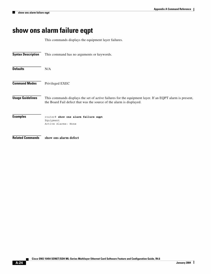
Appendix A Command Referenceshow ons alarm failure eqpt
show ons alarm failure eqptThis commands displays the equipment layer failures.
Syntax Description This command has no arguments or keywords.
Defaults N/A
Command Modes Privileged EXEC
Usage Guidelines This commands displays the set of active failures for the equipment layer. If an EQPT alarm is present, the Board Fail defect that was the source of the alarm is displayed.
Examples router# show ons alarm failure eqptEquipmentActive Alarms: None
Related Commands show ons alarm defect
A-24Cisco ONS 15454 SONET/SDH ML-Series Multilayer Ethernet Card Software Feature and Configuration Guide, R4.6
January 2004
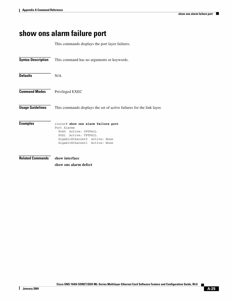
Appendix A Command Referenceshow ons alarm failure port
show ons alarm failure portThis commands displays the port layer failures.
Syntax Description This command has no arguments or keywords.
Defaults N/A
Command Modes Privileged EXEC
Usage Guidelines This commands displays the set of active failures for the link layer.
Examples router# show ons alarm failure portPort Alarms POS0 Active: TPTFAIL POS1 Active: TPTFAIL GigabitEthernet0 Active: None GigabitEthernet1 Active: None
Related Commands show interface
show ons alarm defect
A-25Cisco ONS 15454 SONET/SDH ML-Series Multilayer Ethernet Card Software Feature and Configuration Guide, R4.6
January 2004

Appendix A Command Referenceshow ons alarm failure pos interface-number
show ons alarm failure pos interface-number This commands displays the link layer failures.
Syntax Description
Defaults N/A
Command Modes Privileged EXEC
Usage Guidelines This commands displays the set of active failures for a specific interface at the POS layer. The display also specifies if an alarm has been demoted, as defined in Telcordia GR-253.
Examples router# show ons alarm failure pos 0POS0Active Alarms : NoneDemoted Alarms: None
Related Commands show controller pos
show ons alarm defect
Parameter Description
interface-number Number of the interface (0–1)
A-26Cisco ONS 15454 SONET/SDH ML-Series Multilayer Ethernet Card Software Feature and Configuration Guide, R4.6
January 2004
Appendix A Command Referencespr drpri-id { 0 | 1 }
spr drpri-id { 0 | 1 } Creates a DRPRI identification number of 0 or 1 to differentiate between the ML-Series cards paired for the DRPRI protection feature.
Defaults N/A
Command Modes Shared packet ring (SPR) interface configuration
Usage Guidelines DRPRI paired sets share the same SPR station ID, so the DRPRI identification number helps identify a particular card in a DRPRI pair.
Examples The following example assigns a DRPRI identification number of zero to the SPR interface on an ML-Series card:Router(config)# interface spr 1Router(config-if)# spr drpri-id 0
Related Commands interface spr 1
spr-intf-id
spr station-id
spr wrap
A-27Cisco ONS 15454 SONET/SDH ML-Series Multilayer Ethernet Card Software Feature and Configuration Guide, R4.6
January 2004
Appendix A Command Referencespr-intf-id shared-packet -ring-number
spr-intf-id shared-packet -ring-number Assigns the POS interface to the SPR interface.
Syntax Description
Defaults N/A
Command Modes POS interface configuration
Usage Guidelines • The SPR number must be 1, which is the same SPR number assigned to the SPR interface.
• The members of the SPR interface must be POS interfaces.
• An SPR interface is configured similarly to a EtherChannel (port-channel) interface. Instead of using the channel-group command to define the members, you use the spr-intf-ID command. Llike port-channel, you then configure the SPR interfaces instead of the POS interface.
Examples The following example assigns an ML-Series card POS interface to an SPR interface with a shared-packet-ring-number of 1:Router(config)# interface pos 0Router(config-if)# spr-intf-id 1
Related Commands interface spr 1
spr drpri-id
spr station-id
spr wrap
Parameter Description
shared-packet-ring-number The only valid shared-packet-ring-number (SPR number) is 1.
A-28Cisco ONS 15454 SONET/SDH ML-Series Multilayer Ethernet Card Software Feature and Configuration Guide, R4.6
January 2004
Appendix A Command Reference[no] spr load-balance { auto | port-based }
[no] spr load-balance { auto | port-based }Specifies the RPR load-balancing scheme for Unicast packets.
Syntax Description
Defaults The default setting is auto.
Command Modes SPR interface configuration
Examples The following example configures an SPR interface to use port-based load balancing:Router(config)# interface spr 1Router(config-if)# spr load-balance port-based
Related Commands interface spr 1
Parameter Description
auto The default auto option balances the load based on the MAC addresses or source and destination addresses of the IP packet.
port-based The port-based load balancing option maps even ports to the POS 0 interface and odd ports to the POS 1 interface.
A-29Cisco ONS 15454 SONET/SDH ML-Series Multilayer Ethernet Card Software Feature and Configuration Guide, R4.6
January 2004
Appendix A Command Referencespr station-id station-id-number
spr station-id station-id-number Configures a station ID.
Syntax Description
Defaults N/A
Command Modes SPR interface configuration
Usage Guidelines The different ML-Series cards attached to the RPR all have the same interface type and number, spr1. The station ID helps to differentiate the SPR interfaces.
Examples The following example sets an ML-Series card SPR station ID to 100:Router(config)# interface spr 1 Router(config-if)# spr station-id 100
Related Commands interface spr 1
spr drpri-id
spr-intf-id
spr wrap
Parameter Description
staion-id-number The user must configure a different number for each SPR interface that attaches to the RPR. Valid station ID numbers range from 1 to 254.
A-30Cisco ONS 15454 SONET/SDH ML-Series Multilayer Ethernet Card Software Feature and Configuration Guide, R4.6
January 2004

Appendix A Command Referencespr wrap immediate | delayed
spr wrap immediate | delayed Sets the RPR wrap mode to either wrap traffic the instant it detects a link state change or to wrap traffic after the carrier delay, which gives the SONET protection time to register the defect and declare the link down.
Syntax Description
Defaults The default setting is immediate.
Command Modes SPR interface configuration
Usage Guidelines Immediate should be used if RPR is running over unprotected SONET circuits. Delayed should be run for SONET protected circuits (BLSR or path protection).
Examples The following example sets an ML-Series card to delayed:Router(config)# interface spr 1 Router(config-if)# spr wrap delayed
Related Commands interface spr 1
spr drpri-id
spr-intf-id
spr station-id
Parameter Description
immediate Wraps RPR traffic the instant it detects a link state change. delayed Wraps RPR traffic after the carrier delay time expires.
A-31Cisco ONS 15454 SONET/SDH ML-Series Multilayer Ethernet Card Software Feature and Configuration Guide, R4.6
January 2004

Appendix A Command Referencespr wrap immediate | delayed
A-32Cisco ONS 15454 SONET/SDH ML-Series Multilayer Ethernet Card Software Feature and Configuration Guide, R4.6
January 2004
Cisco ONS 15454 SONET/SDH ML-Series Multilayer Ethernet Card SoftwarJanuary 2004
A P P E N D I X B
Unsupported CLI CommandsThis appendix lists some of the command-line interface (CLI) commands that are not supported in this release, either because they are not tested, or because of hardware limitations. These unsupported commands are displayed when you enter the question mark (?) at the CLI prompt. This is not a complete list. Unsupported commands are listed by command mode.
Unsupported Privileged Exec Commandsclear ip accounting
show ip accounting
show ip cache
show ip tcp header-compression
show ip mcache
show ip mpacket
Unsupported Global Configuration Commandsaccess-list aaa <1100-1199>
access-list aaa <200-299>
access-list aaa <700-799>
async-bootp
boot
bridge <num> acquire
bridge <num> address
bridge cmf
bridge <num> bitswap-layer3-addresses
bridge <num> circuit-group
bridge <num> domain
bridge <num> lat-service-filtering
bridge <num> protocol dec
B-1e Feature and Configuration Guide, R4.6

Appendix B Unsupported CLI CommandsUnsupported Global Configuration Commands
bridge <num> protocol ibm
bridge <num> protocol vlan-bridge
chat-script
class-map match access-group
class-map match class-map
class-map match destination-address
class-map match mpls
class-map match protocol
class-map match qos-group
class-map match source-address
clns
define
dialer
dialer-list
downward-compatible-config
file
ip access-list log-update
ip access-list logging
ip address-pool
ip alias
ip bootp
ip gdp
ip local
ip reflexive-list
ip security
ip source-route
ip tcp
ipc
map-class
map-list
multilink
netbios
partition
policy-map class queue-limit
priority-list
queue-list
router iso-igrp
router mobile
B-2Cisco ONS 15454 SONET/SDH ML-Series Multilayer Ethernet Card Software Feature and Configuration Guide, R4.6
January 2004
Appendix B Unsupported CLI CommandsUnsupported POS Interface Configuration Commands
service compress-config
service disable-ip-fast-frag
service exec-callback
service nagle
service old-slip-prompts
service pad
service slave-log
subscriber-policy
Unsupported POS Interface Configuration Commandsaccess-expression
autodetect
bridge-group x circuit-group
bridge-group x input-*
bridge-group x lat-compression
bridge-group x output-*
bridge-group x subscriber-loop-control
clock
clns
custom-queue-list
down-when-looped
fair-queue
flowcontrol
full-duplex
half-duplex
hold-queue
ip accounting
ip broadcast-address
ip load-sharing per-packet
ip route-cache
ip security
ip tcp
ip verify
iso-igrp
loopback
multilink-group
netbios
B-3Cisco ONS 15454 SONET/SDH ML-Series Multilayer Ethernet Card Software Feature and Configuration Guide, R4.6
January 2004
Appendix B Unsupported CLI CommandsUnsupported FastEthernet or GigabitEthernet Interface Configuration Commands
priority-group
pulse-time
random-detect
rate-limit
rmon
serial
service-policy history
source
timeout
transmit-interface
tx-ring-limit
Unsupported FastEthernet or GigabitEthernet Interface Configuration Commands
access-expression
clns
custom-queue-list
fair-queue
hold-queue
ip accounting
ip broadcast-address
ip load-sharing per-packet
ip route-cache
ip security
ip tcp
ip verify
iso-igrp
keepalive
loopback
max-reserved-bandwidth
multilink-group
netbios
priority-group
random-detect
rate-limit
service-policy history
B-4Cisco ONS 15454 SONET/SDH ML-Series Multilayer Ethernet Card Software Feature and Configuration Guide, R4.6
January 2004
Appendix B Unsupported CLI CommandsUnsupported Port-Channel Interface Configuration Commands
timeout
transmit-interface
tx-ring-limit
Unsupported Port-Channel Interface Configuration Commandsaccess-expression
carrier-delay
cdp
clns
custom-queue-list
duplex
down-when-looped
encapsulation
fair-queue
flowcontrol
full-duplex
half-duplex
hold-queue
iso-igrp
keepalive
max-reserved-bandwidth
multilink-group
negotiation
netbios
ppp
priority-group
rate-limit
random-detect
timeout
tx-ring-limit
Unsupported BVI Interface Configuration Commandsaccess-expression
carrier-delay
cdp
clns
B-5Cisco ONS 15454 SONET/SDH ML-Series Multilayer Ethernet Card Software Feature and Configuration Guide, R4.6
January 2004

Appendix B Unsupported CLI CommandsUnsupported BVI Interface Configuration Commands
flowcontrol
hold-queue
iso-igrp
keepalive
l2protocol-tunnel
load-interval
max-reserved-bandwidth
mode
multilink-group
netbios
ntp
mtu
rate-limit
timeout
transmit-interface
tx-ring-limit
B-6Cisco ONS 15454 SONET/SDH ML-Series Multilayer Ethernet Card Software Feature and Configuration Guide, R4.6
January 2004
Cisco ONS 15454 SONET/SDH ML-Series Multilayer Ethernet Card SoftwarJanuary 2004
A P P E N D I X C
Using Technical SupportThis appendix describes how to resolve problems with your ML-Series card.
The appendix contains the following sections:
• Gathering Information About Your Internetwork, page C-1
• Getting the Data from Your ML-Series Card, page C-2
• Providing Data to Your Technical Support Representative, page C-3
To help resolve these problems, use the “Gathering Information About Your Internetwork” section on page C-1 as a guideline for gathering relevant information about your network prior to calling.
Note When you have a problem that you cannot resolve, contact the Cisco Technical Assistance Center (Cisco TAC).
Gathering Information About Your InternetworkBefore gathering any specific data, compile a list of all symptoms that users have reported on the internetwork (such as connections dropping or slow host response).
The next step is to gather specific information. Typical information needed to troubleshoot internetworking problems falls into two general categories: information required for any situation; and information specific to the topology, technology, or protocol.
Information that is always required by technical support engineers includes the following:
• Network topology map for the data network and the SONET/SDH topology and provisioning.
• List of hosts and servers: Include the host and server type, number on network, and a description of the host operating systems that are implemented.
• Configuration listing of all switch routers and switches involved.
• Complete specifications of all switch routers and switches involved.
• Version numbers of software (obtained with the show version command) and Flash code (obtained with the show controllers command) on all relevant switch routers and switches.
• List of network layer protocols, versions, and vendors.
• List of alarms and conditions on all nodes in the SONET/SDH topology.
• Node equipment and configuration; including type of cross-connect cards, ML-Series cards’ slot numbers, OC-N cards, and TCC2 cards.
C-1e Feature and Configuration Guide, R4.6
Appendix C Using Technical SupportGetting the Data from Your ML-Series Card
To assist you in gathering this required data, the show tech-support EXEC command has been added in Cisco IOS Release 11.1(4) and later. This command provides general information about the switch router that you can provide to your technical support representative when you are reporting a problem.
The show tech-support command outputs the equivalent of the show version, show running-config, show controllers, show stacks, show interfaces, show buffers, show process memory, and show process EXEC commands.
The specific information requirements that might be needed by technical support vary depending on the situation. They include the following:
• Output from the following general show commands:
show interfaces
show controllers
show processes {cpu | mem}
show buffer
show mem summary
• Output from the following protocol-specific show commands:
show protocol route
show protocol traffic
show protocol interfaces
show protocol arp
• Output from provisioning show commands
• Output from relevant debug privileged EXEC commands
• Output from protocol-specific ping and trace diagnostic tests, as appropriate
• Network analyzer traces, as appropriate
• Core dumps obtained using the exception dump command, or using the write core command if the system is operational, as appropriate
Getting the Data from Your ML-Series CardWhen obtaining the information from your ML-Series card, you must tailor your method to the system that you are using to retrieve the information. Following are some hints for different platforms:
• PC and Macintosh—Connect a PC or Macintosh to the console port of the ML-Series card and log all output to a disk file (using a terminal emulation program). The exact procedure varies depending on the communication package used with the system.
• Terminal connected to the console port or remote terminal—The only way to get information with a terminal connected to the console port or with a remote terminal is to attach a printer to the AUX port on the terminal (if one exists) and to force all screen output to go to the printer. Using a terminal is undesirable because there is no way to capture the data to a file.
• UNIX workstation—At the UNIX prompt, enter the command script filename, then use Telnet to connect to the ML-Series card. The UNIX script command captures all screen output to the specified filename. To stop capturing output and close the file, enter the end-of-file character (typically Ctrl-D) for your UNIX system.
C-2Cisco ONS 15454 SONET/SDH ML-Series Multilayer Ethernet Card Software Feature and Configuration Guide, R4.6
January 2004
Appendix C Using Technical SupportProviding Data to Your Technical Support Representative
Note To get your system to automatically log specific error messages or operational information to a UNIX syslog server, enter the logging internet-address command. For more information about using the logging command and setting up a syslog server, refer to the Cisco IOS configuration guides and command references.
Providing Data to Your Technical Support RepresentativeWhen submitting information to your technical support representative, electronic data is preferred. Electronic data significantly eases the transfer of information between technical support personnel and development staff. Common electronic formats include data sent through electronic mail and files sent using FTP.
If you are submitting data to your technical support representative, use the following list (in order of most to least favorable) to determine the preferred method for submission:
• The preferred method of information submission is through FTP service over the Internet. If your environment supports FTP, you can place your file in the incoming directory on the host Cisco.com.
• The next best method is to send data by e-mail. Before using this method, be sure to contact your technical support representative, especially when transferring binary core dumps or other large files.
• Transfer through a PC-based communications protocol, such as Kermit, to upload files to Cisco.com. Again, be sure to contact your technical support representative before attempting any transfer.
• Transfer by disk or tape.
• The least favorable method is hard-copy transfer by fax or physical mail.
Note If you use e-mail, do not use encoding methods such as binhex or zip. Only MIME-compliant mail should be used.
C-3Cisco ONS 15454 SONET/SDH ML-Series Multilayer Ethernet Card Software Feature and Configuration Guide, R4.6
January 2004

Appendix C Using Technical SupportProviding Data to Your Technical Support Representative
C-4Cisco ONS 15454 SONET/SDH ML-Series Multilayer Ethernet Card Software Feature and Configuration Guide, R4.6
January 2004
Cisco ONS 15454 SONET/SDH ML-Series Multilayer Ethernet Card Software FeJanuary 2004
I N D E X
Numerics
802.1D. See STP
802.1Q. See IEEE 802.1Q
A
abbreviating commands 3-14
ABRs 10-10
access control lists. See ACL
ACL
about 15-1
applying ACLs 15-4
creating
extended IP ACLs 15-3
IP ACLs 15-3
named extended IP ACLs 15-4
named IP ACLs 15-3
named standard IP ACLs 15-4
numbered standard IP ACLs 15-3
implementation guidelines IP ACL 15-2
named IP ACL 15-2
adapter cable 3-4
addresses
dynamic
accelerated aging 6-9
default aging 6-9
multicast, STP address management 6-8
administrative distances
OSPF 10-17
routing protocol defaults 10-32
advertisements RIP 10-5
aging time, accelerated for STP 6-9, 6-20
alarms 4-15
area border routers. See ABRs
ASBRs 10-10
autonomous system boundary routers. See ASBRs
B
bandwidth command traffic classes 13-13
BGP, about 10-27
Border Gateway Protocol. See BGP
BPDU RSTP format 6-13
bridge-group command 4-4, 4-5, 4-12, 5-2, 17-8
bridge groups, routing 11-1
bridge-group virtual interface See BVIs
bridge irb command 11-3
bridge priority command 5-2
bridge protocol command 5-2, 17-8
bridging
configuring 5-2
description 5-1
feature list 1-2
monitoring and verifying 5-3
bvi command 11-3
BVIs
configuring 11-3
description 11-1
displaying information about 11-5
routing enabled on 11-2
C
cable, RJ-11 to RJ-45 adapter 3-4
card description 1-1
IN-1ature and Configuration Guide, R4.6
Index
CDP, Layer 2 protocol tunneling 8-10
channel-group command 9-3, 9-5
Cisco IOS
backing out one level 3-14
bridging functionality 5-1
command modes 3-13 to 3-15
console configuration mode 3-14
global configuration mode 3-13
interface configuration mode 3-14
listing commands 3-15
privileged EXEC mode 3-13
software basics 3-13
startup configuration file 3-9
upgrading image 1-4
user EXEC mode 3-13
clear bridge command 5-3
clear vlan command 7-5
clear vlan statistics command 5-3
clocking tolerances 1-9
commands
bridge-group 4-4, 4-5, 4-12, 5-2, 17-8
bridge irb 11-3
bridge priority 5-2
bridge protocol 5-2, 17-8
bridge protocol drpri-rstp A-2
channel-group 9-3, 9-5
clear bridge 5-3
clear vlan 7-5
clear vlan statistics 5-3
debug vlan packet 7-5
hostname 3-9
interface bvi 11-3
interface spr 1 A-4
ip multicast-routing 10-34
ip pim 10-34
line vty 3-8
listing 3-15
network area 10-3
reference chapter A-1
IN-2Cisco ONS 15454 SONET/SDH ML-Series Multilayer Ethernet Card
router bgp 10-3
router eigrp 10-2
router ospf 10-3
sdm size 14-3
show bridge 5-3
show bridge group 5-3
show interfaces bvi 11-5
show interfaces irb 11-5
show interfaces port-channel 9-9
show ip mroute 10-35
show sdm size 14-3
show span 5-3
show tech-support C-2
show vlan 7-5
show vlans 5-3
spri drpri-id A-27
spr-intf-id A-28
spr station-id A-30
spr wrap A-31
configuration mode
console 3-14
global 3-13
configuring
bridging 5-1
BVIs 11-3
EtherChannel encapsulation 9-7
Fast EtherChannel 9-1
host name 3-9
integrated routing and bridging See IRB
interface, overview 4-1
IP 10-1
IP multicast 10-33
ISL over FEC 9-7
management port 3-8
VLANs 7-1
connecting to console port 3-5
connection procedures 3-5 to 3-6
console port, connecting to 3-5
CoS-based Packet Statistics 13-22
Software Feature and Configuration Guide, R4.6January 2004
Index
CoS-based QoS 13-16
cos commit command 13-16
CTC
Cisco IOS on CTC 3-2
Ethernet port provisioning information 2-5
Ethernet statistics 2-1
POS port provisioning information 2-7
POS statistics 2-3
SONET alarms 2-8
SONET circuit provisioning 2-9
D
debug vlan packet command 7-5
default configuration
EIGRP 10-21
Layer 2 protocol tunneling 8-11
OSPF 10-10
RIP 10-5
STP 6-16
dense mode, PIM 10-34
Diffusing Update Algorithm (DUAL) 10-20
double-tagged packets
IEEE 802.1Q tunneling 8-2
Layer 2 protocol tunneling 8-11
DRPRI
configuring 16-12
example 16-12
overview 1-5
understanding 16-10
DUAL finite state machine, EIGRP 10-20
dynamic addresses. See addresses
E
EIGRP
authentication 10-24
components 10-20
Cisco ONS 15454 SONET/SDH ML-Series Multilayer EJanuary 2004
configuring 10-22
default configuration 10-21
definition 10-20
interface parameters, configuring 10-23
monitoring 10-25
e-mail, technical support C-3
enable mode 3-13
enable passwords 3-7
enable secret passwords 3-7
encapsulation
configuring EtherChannels 9-7
configuring IEEE 802.1Q VLANs 7-2
Enhanced IGRP. See EIGRP
Enhanced performance monitoring 13-22
error messages, logging C-3
EtherChannel
configuring encapsulation 9-7
ISL VLANs 9-1
port channels supported 9-1
Ethernet
clocking 1-9
Ethernet configuration tasks 4-4
Ethernet Relay Multipoint Service (ERMS) 8-7
Ethernet Wire Service (EWS) 8-7
extended system ID, STP 6-4
F
Fast EtherChannel. See FEC
Fast Ethernet
configuring autonegotiation 4-4
configuring interfaces 4-4
Fast EtherChannel 9-1
feature list 1-2
FEC
cautions 9-2, 9-5, 12-2
configuring 9-2, 9-4, 12-2
configuring encapsulation 9-7
configuring ISL 9-7
IN-3thernet Card Software Feature and Configuration Guide, R4.6

Index
port channels supported 9-1
FPGA 2-9
G
GEC
bandwidth scalability 9-2
configuring 9-2, 9-4, 12-2
configuring encapsulation 9-7
Gigabit EtherChannel. See GEC
Gigabit Ethernet
configuring autonegotiation 4-5, 4-12
configuring interfaces 4-5, 4-12
global configuration mode 3-13
H
hostname command 3-9
HSRP, EtherChannel compatibility with 9-1
I
IEEE 8-4
IEEE 802.1D. See STP
IEEE 802.1Q tunneling
compatibility with other features 8-4
defaults 8-4
described 8-1
IGMP 10-33
IGP 10-9
integrated routing and bridging See IRB
interface configuration mode 3-14
interface parameters, configuring
EtherChannel 9-2, 9-5, 12-2
general 4-3
overview 4-1
interface port IDs 4-2
Interior Gateway Protocol. See IGP
IN-4Cisco ONS 15454 SONET/SDH ML-Series Multilayer Ethernet Card
Internet Group Membership Protocol. See IGMP
Internet protocol multicast. See IP multicast routing
Inter-Switch Link protocol. See ISL
IOS. See Cisco IOS
IOS commands A-1
IP access control list. See ACL
IP multicast routing
description 10-33
IGMP 10-33
PIM 10-33
ip multicast-routing command 10-34
ip pim command 10-34
IP routes, monitoring 10-33
IP routing protocols, configuration tasks 10-1
IP unicast routing
administrative distances 10-32
configuring static routes 10-31
IGP 10-9
IRB
BVIs 11-1
configuration considerations 11-1
configuring 11-2
description 11-1
displaying information about 11-5
monitoring and verifying 11-4
ISL 9-1
J
J1 bytes 2-10
K
keepalive command 4-14
Kermit protocol C-3
Software Feature and Configuration Guide, R4.6January 2004
Index
L
Layer 2 feature list 1-2
Layer 2 protocol tunneling 8-10
configuring 8-10
default configuration 8-11
defined 8-10
guidelines 8-11
Layer 3 feature list 1-4
line vty command 3-8
link state advertisements (LSAs) 10-14
logging command C-3
logging router output C-2
M
MAC addresses 4-2
management ports
See also console ports
configuring 3-8
match any command 13-11
match cos command 13-11
match ip dscp command 13-12
match ip precedence command 13-12
Media Access Control addresses. See MAC addresses
message logging C-3
metro tags 8-2
Modular QoS Command-Line Interface
configuration (example) 13-17
configuration, verifying 13-16
configuring 13-10
monitoring
EIGRP 10-25
IEEE 802.1Q tunneling 8-13
IP routes 10-33
Layer 2 protocol tunneling 8-13
OSPF 10-19, 10-32
tunneling 8-13
MSTP, interoperability with IEEE 802.1D 6-15
Cisco ONS 15454 SONET/SDH ML-Series Multilayer EJanuary 2004
MST protocol tunneling 8-10
multicast, IP. See IP multicast routing
N
neighbor discovery/recovery, EIGRP 10-20
networking protocols, IP multicast routing 10-33 to 10-34
not-so-stubby areas. See NSSA
NSSA, OSPF 10-14
O
OSPF
area parameters, configuring 10-14
configuring 10-3, 10-11
default configuration
metrics 10-17
route 10-16
settings 10-10
described 10-9
interface parameters, configuring 10-13
LSA group pacing 10-18
monitoring 10-19, 10-32
network area command 10-3
process ID 10-3
router IDs 10-19
route summarization 10-16
virtual links 10-16
P
passive interface OSPF 10-17
passwords 3-7
path cost for STP 6-18
PC, connecting to switch 3-5
per-VLAN Spanning Tree+ 6-8
PIM
configuring 10-34
IN-5thernet Card Software Feature and Configuration Guide, R4.6
Index
modes 10-33 to 10-34
rendezvous point 10-34
pin mappings for RJ-11 to RJ-45 3-4
port-channel command 9-1
port channels 9-1
port IDs 4-2
port priority, STP 6-17
POS
configuring interfaces 4-12
description 4-8
SONET alarms 4-16, 4-17
pos delay triggers command 4-17
pos report command 4-16
pos scramble-atm command 4-15
privileged EXEC mode 3-13
procedures, connection 3-5 to 3-6
protocol-dependent modules, EIGRP 10-21
Protocol Independent Multicast. See PIM
PVST+. See per-VLAN Spanning Tree+
Q
QinQ 8-1
QoS policers 13-14
R
reliable transport protocol, EIGRP 10-20
remote terminals, logging router output C-2
rendezvous points 10-34
RFC
1058, RIP 10-5
1253, OSPF 10-9
1587, NSSAs 10-9
RIP
advertisements 10-5
authentication 10-8
configuring 10-6
IN-6Cisco ONS 15454 SONET/SDH ML-Series Multilayer Ethernet Card
default configuration 10-5
described 10-5
hop counts 10-5
split horizon 10-8
summary addresses 10-8
RJ-11 to RJ-45 console cable adapter 3-4
RJ-45 connector, console port 3-6
RMON
ML-Series 1-6
route calculation timers, OSPF 10-17
router bgp command 10-3
router eigrp command 10-2
router ID, OSPF 10-19
router isis command 10-29
router ospf command 10-3
route summarization, OSPF 10-16
routing protocol administrative distances 10-32
RPF 10-34
RPR
carrier delay 16-3
configuring 16-4
CoS-based QoS 13-16
DRPRI 16-10
example 16-8
MAC address and VLAN support 16-4
overview 1-6
QoS 13-10
understanding 16-1
RSTP
overview 6-9
active topology, determining 6-10
BPDU
format 6-13
processing 6-14
designated port, defined 6-10
designated switch, defined 6-10
interoperability with IEEE 802.1D
described 6-15
topology changes 6-14
Software Feature and Configuration Guide, R4.6January 2004
Index
port roles
described 6-10
synchronized 6-12
proposal-agreement handshake process 6-11
rapid convergence
point-to-point links 6-11
root ports 6-11
root port, defined 6-10
S
script command C-2
SDH
alarms 1-6
bandwidth 1-5
encapsulation 1-7
SDH alarms 4-15
SDM
See also TCAM
configuring
autolearn 14-2
size 14-2
regions 14-1
sdm access-list command 14-3
sdm size command 14-3
service-policy command, traffic policies 13-15
service-policy input command 13-16
service-policy output command 13-16
service-provider networks
and customer VLANs 8-2
and IEEE 802.1Q tunneling 8-1
Layer 2 protocols across 8-10
set qos-group command 13-15
show bridge command 5-3
show bridge group command 5-3
show interfaces bvi command 11-5
show interfaces irb command 11-5
show interfaces port-channel command 9-9
show ip mroute command 10-35
Cisco ONS 15454 SONET/SDH ML-Series Multilayer EJanuary 2004
show policy-map command 13-16
show sdm size command 14-3
show span command 5-3
show tech-support command C-2
show vlan command 7-5
show vlans command 5-3
SNMP 1-4
SONET
alarms 1-6
bandwidth 1-5
encapsulation 1-7
SONET alarms 4-15
sparse mode, PIM 10-34
startup configuration file 3-9
static routes, configuring 10-31
statistics, OSPF 10-19, 10-32
STP
BPDU message exchange 6-2
configuring
forward-delay time 6-20
hello time 6-19
path cost 6-18
port priority 6-17
root switch 6-17
switch priority 6-19
default configuration 6-16
designated port, defined 6-3
designated switch, defined 6-3
disabling 6-16
displaying status 6-20
extended system ID
overview 6-4
unexpected behavior 6-17
forward-delay time 6-6
inferior BPDU 6-3
interface states
blocking 6-6
disabled 6-7
forwarding 6-6, 6-7
IN-7thernet Card Software Feature and Configuration Guide, R4.6
Index
learning 6-7
listening 6-7
overview 6-5
Layer 2 protocol tunneling 8-10
limitations with IEEE 802.1Q trunks 6-8
multicast addresses, affect of 6-8
overview 6-2
redundant connectivity 6-8
root port, defined 6-3
root switch
effects of extended system ID 6-4
election 6-3
unexpected behavior 6-17
superior BPDU 6-3
supported number of spanning-tree instances 6-2, 6-9
timers, described 6-4
stub areas, OSPF 10-14
support, technical. See technical support
SW-LCAS 1-7
syslog server C-3
system MTU
IEEE 802.1Q tunneling 8-4
maximums 8-4
T
tagged packets, Layer 2 protocol 8-10
TCAM
See also SDM
entries 14-2
Layer 3 switching information 14-1
protocol regions 14-1
space 14-1
technical support
FTP service C-3
gathering data C-1
logging router output C-2
providing data C-3
show tech-support command C-2
IN-8Cisco ONS 15454 SONET/SDH ML-Series Multilayer Ethernet Card
terminals
connecting to switch 3-5
terminal-emulation software 3-5
terminals, logging router output C-2
ternary content addressable memory. See TCAM
traffic classes 13-11
traffic policies
creating 13-12
interfaces, attaching 13-15
trunk ports 7-1
tunneling
defined 8-1
IEEE 802.1Q 8-1
Layer 2 protocol 8-10
tunnel ports
described 8-1
IEEE 802.1Q, configuring 8-4, 8-12, 8-13
incompatibilities with other features 8-4
U
user EXEC mode 3-13
V
verifying
10/100BASE-T configuration 4-6
IP multicast operation 10-35
VLAN operation 7-5
virtual LANs. See VLANs
VLANs
aging dynamic addresses 6-9
configuring IEEE 802.1Q 7-2
customer numbering in service-provider networks 8-3
number per system 7-1
STP and IEEE 802.1Q trunks 6-8
trunk ports 7-1
VLAN-specific services 8-7
Software Feature and Configuration Guide, R4.6January 2004

Index
VRF Lite
configuring 12-2
example 12-2
monitoring and verifying 12-7
understanding 12-1
VTP Layer 2 protocol tunneling 8-10
vty 3-4
Cisco ONS 15454 SONET/SDH ML-Series Multilayer EJanuary 2004
IN-9thernet Card Software Feature and Configuration Guide, R4.6

Index
IN-10Cisco ONS 15454 SONET/SDH ML-Series Multilayer Ethernet Card
Software Feature and Configuration Guide, R4.6January 2004