cisco crs carrier routing system ethernet physical layer ... · pdf file1-geplims 10...
TRANSCRIPT

Cisco CRS Carrier Routing System Ethernet Physical Layer InterfaceModule Installation Note
Cisco CRS Carrier Routing System Ethernet Physical Layer Interface Module Installation
Note 2
Changes to This Document 2
Important Information 4
About Physical Layer Interface Modules 8
1-GE PLIMs 10
10-GE PLIMs 29
40-GE PLIMs 76
100-GE PLIMs 82
Combination PLIMs 90
How to Remove or Install a PLIM 97
Verifying the Installation of a PLIM 101
How to Remove or Install a PLIM Cable Management Bracket 101
Before You Remove or Install a Transceiver Module 108
About PLIM Impedance Carriers 111
Regulatory, Compliance, and Safety Information 111
Obtaining Documentation and Submitting a Service Request 112
Revised: December 7, 2016,
Cisco CRS Carrier Routing System Ethernet Physical LayerInterface Module Installation NoteThis document describes the various Ethernet physical layer interface modules (PLIMs) used in the Cisco CRS-1 Carrier RoutingSystem 16-slot, 8-slot, and 4-slot line card chassis (LCC). It provides an overview of the different Ethernet PLIMs and providesinstructions on how to remove and install a PLIM and its associated components.
Changes to This DocumentThe following table lists the technical changes made to this document since it was first printed.
Table 1: Changes to This Document
Change SummaryDate
Added information about the supported SR-4 breakout cablefor 2-port 100-GE and 5-port 40-GE QSFP+ CombinationPLIM.
September 2015
Added information about the new 2-port 100-GE and 5-port40-GE QSFP+ combination PLIM. Also added section aboutthe QSFP+ modules.
July 2014
Added information about the new 40-port 10-GE SFP+ PLIMand the new 4-port 100-GE CPAK PLIM. Also added sectionsabout the SFP+ and CPAK modules.
January 2014
Added information about replacing an SFP on a line card thatuses an articulated bracket.
June 2013
Added information about the new 1-port 100-GE IPoDWDMPLIM and the new 2-port and 4-port 40-GEOTU3CFP PLIMs.
September 2012
Added information about the CFP-100G-SR10 optical moduleon the Cisco CRS-3 Series Router platform.
This CFP-100G-SR10 optical module enables connection tothe Cisco CRS-3 Series Router 1-port 100-GE PLIM usingmultimode fiber rather than only single mode fiber.
May 2012
Added information about the articulated cable bracket for the20-port 1-GE FLEX PLIM and the 42-port 1-GE XFP PLIMto the Removing a PLIMCableManagement Bracket, on page104 section and the Installing a PLIM Cable ManagementBracket, on page 108 section.
February 2012
2

Change SummaryDate
Added information about XFP power budgeting for the 20-portand 14-port 10-GE XFP PLIMs. Added information aboutadditional 10-GE and DWDMXFP modules supported on the20-port, 14-port, 8-port, and 4-port 10-GE XFP PLIMS.
June 2011
Added information about SPAs supported by the 20-port 1-GEFLEX PLIM and the 2-port 10-GE FLEX PLIM.
November 2010
Added information about new 20-port and 14-port 10-GEXFPPLIMs.
October 2010
Added information about new 8-port and 4-port 10-GE XFPPLIMs, and added optics information about XFP modules forthe new PLIMs.
April 2010
Corrections were made to the 4-port 10-GE PLIM, 42-port1-GE PLIM, 20-port 1-GE FLEX PLIM, and 2-port 10-GEFLEX PLIM.
July 2009
Added information about the extended-wavelength GE opticsmodule to the Ethernet PLIMs, on page 8 section and AboutPLIM Impedance Carriers, on page 111 section.
February 2007
• Added information about the 4-port 10-GE WDMPHYPLIM to the 10-GE Tunable WDMPHY PLIM, on page45 section.
• Added cable management information to the How toRemove or Install a PLIM Cable Management Bracket,on page 101 section.
• Added optics information for all GE PLIMs to the AboutPLIM Impedance Carriers, on page 111 section.
July 2006
3

Change SummaryDate
• Reorganized part numbers and related documentationinto the Important Information, on page 4 section.
• Added information about DWDM optics modules to the8-Port 10-GE PLIM with XENPAK Optics Modules ,on page 34 section.
• Corrected product number from XENPAK-10GB-LR toCRS-XENPAK10GB-LR.
• Revised Figure 20: 8-Port 10-GE PLIM Front Panel toshow more details.
• Removed cable management bracket information fromthe Guidelines for Card Installation and Removal, onpage 109 section because that procedure is described ininstallation guides.
• The following changes were made in the How to Removeor Install a PLIM Cable Management Bracket, on page101 section:
◦Added Caution about using the shutdowncommand before removing a XENPAK module.
◦Added the Prerequisites, on page 71 section toexplain how to determine if an attenuator is needed.
◦Term “slot” was changed to “port” in regard to theXENPAK receptacles. The DWDM XENPAKmodule is now shown in Figure 34: DWDMXENPAK Optics module .
• Added the “Reporting Security Problems in CiscoProducts” section.
• Removed references to POS PLIMs.
March 2006
Initial release of the document.November 2004
Important InformationThis section contains the following sections:
Product NumbersThe following table lists the Cisco product numbers for the products to which this publication applies.
4

Table 2: PLIM Descriptions and Software and Hardware Compatibility
Hardware RevisionNumber
Minimum Cisco IOSXR Release
DescriptionProduct NumberName
—5.1.3Cisco CRS 2-port100-GE and 5-port40-GE QSFP+combination PLIM
2X100GE-FLEX-40=2x100-G and 5-x40-GEQSFP+ combinationPLIM
—5.1.1Cisco CRS 4-port100-GE LAN/OTNCPAK PLIM
4x100GE-LO=4x100-GECPAKPLIM
—5.1.1Cisco CRS 40-port10-GEWAN/LAN/OTNSFP+PLIM
40x10GE-WLO=40x10-GE SFP+ PLIM
—4.2.3Cisco CRS 1-port100-GE IP overDWDM PLIM
1-100GE-DWDM/C1x100-GE IPoDWDMPLIM
—4.2.3Cisco CRS 2-port40-GE CFP PLIM
2-40GE-L/OTN2x40-GE OTU3 CFPPLIM
—4.2.3Cisco CRS 4-port40-GE CFP PLIM
4-40GE-L/OTN4x40-GE OTU3 CFPPLIM
—4.0.0Cisco CRS 1-port100-GE CFP PLIM
1X100GBE1x100-GE CFP PLIM
—4.0.0Cisco CRS 20-port10-GEWAN/LANXFPPLIM
20X10GBE-WL-XFP20x10-GE XFP PLIM
—4.0.0Cisco CRS 14-port10-GEWAN/LANXFPPLIM
14X10GBE-WL-XFP14x10-GE XFP PLIM
—3.8.4Cisco CRS-1 8-port10-GEWAN/LANXFPPLIM
8-10GBE-WL-XFP8x10-GE XFP PLIM
—3.8.4Cisco CRS-1 4-port10-GEWAN/LANXFPPLIM
4-10GBE-WL-XFP4x10-GE XFP PLIM
—3.8.1Cisco CRS-1 4-port10-GE PLIM
4-10GE=4x10-GE PLIM
5

—3.8.1Cisco CRS-1 42-port1-GE PLIM
42-1GE=42x1-GE PLIM
—3.8.1Cisco CRS-1 20-port1-GE Flexible InterfaceModule
20-1GE-FLEX=20x1-GE-FLEX
—3.8.12x10-GE WAN/LANFlexible InterfaceModule
2-10GE-WL-FLEX2-10GE-WL-FLEX=2x10-GE FLEX
73-10209-02 A03.3Cisco CRS-1 4-Port10-GE (C-band)DWDM PLIM
4-10GE-ITU/C=4x10-GE DWDMPLIM
73-9231-08 A03.08-port 10-GE PLIMusing XENPAK opticsmodules:
• From 1 to 8single-mode,10-GE opticsmodules:CRS-XENPAK10GB-LR=CRS-XENPAK10GB-LR+=CRS-XENPAK10GB-ER+=
• From 1 to 4DWDM opticsmodules:DWDM-XENPAK-60.61=toDWDM-XENPAK-30.33=
AllDWDMXENPAKpartnumbersare listedin Table17:DWDMXENPAKOpticsModules.
Note
8-10GBE=8x10-GE XENPAKPLIM
—3.0Blank card carrier foreach empty PLIM slot(required for EMIcompliance andcooling)
CRS-INT-IMPEDANCE=PLIM impedance carrier
6

Router Hardware InstallationFor hardware installation and configuration information for the Cisco CRS-1, see the router hardware installation documents in theRelated Documentation, on page 7 section. These documents include information on the router switch fabric and how it affectsoperation of the PLIM. They also include PLIM slot locations and other requirements.
The PLIMs described in this document are supported on the 16-slot, 8-slot, and 4-slot Cisco CRS line card chassis.
Cisco IOS XR Software Release RequirementsThe above table lists the Cisco IOS XR releases that are compatible with the CRS PLIMs.
For software configuration information, see the Cisco IOS XR software configuration and command reference publications for theinstalled Cisco IOS XR release at:
http://www.cisco.com/en/US/products/ps5763/products_installation_and_configuration_guides_list.html
See the Cisco IOS XR software release notes for additional software release information at:
http://www.cisco.com/en/US/products/ps5763/prod_release_notes_list.html
Hardware Revision RequirementsTo ensure compatibility with the software, your Ethernet PLIM should have a specific hardware revision number. This number isprinted on a label affixed to the component side of the PLIM. The hardware revision number can also be displayed using the showdiag command. Minimum revision numbers are listed in the above table.
Related DocumentationFor complete planning, installation, and configuration information, see the documents for your chassis type (16-slot, 8-slot, or 4-slot)listed in this section. Cisco CRS-1 product documentation is available on line at:
http://www.cisco.com/univercd/cc/td/doc/product/core/crs/index.htm
Hardware Documents
• Cisco CRS Carrier Routing System 16-Slot Line Card Chassis Site Planning Guide
• Cisco CRS Carrier Routing System 8-Slot Line Card Chassis Site Planning Guide
• Cisco CRS Carrier Routing System 4-Slot Line Card Chassis Site Planning Guide
• Cisco CRS Carrier Routing System 16-Slot Line Card Chassis System Description
• Cisco CRS Carrier Routing System 8-Slot Line Card Chassis System Description
• Cisco CRS Carrier Routing System 4-Slot Line Card Chassis System Description
• Cisco CRS Carrier Routing System 16-Slot Line Card Chassis Unpacking, Moving, and Securing Guide (attached to the crate)
• Cisco CRS Carrier Routing System 8-Slot Line Card Chassis Unpacking, Moving, and Securing Guide (attached to the crate)
• Cisco CRS Carrier Routing System 4-Slot Line Card Chassis Unpacking, Moving, and Securing Guide (attached to the crate)
• Cisco CRS Carrier Routing System 16-Slot Line Card Chassis Installation Guide
7

• Cisco CRS Carrier Routing System 8-Slot Line Card Chassis Installation Guide
• Cisco CRS Carrier Routing System 4-Slot Line Card Chassis Installation Guide
• Regulatory Compliance and Safety Information for the Cisco CRS-1 Carrier Routing System (ships with the product)
Software Documents
For a complete listing of software documentation available for the Cisco CRS-1, see About Cisco IOS XR Software Documentationfor your release, available on line at:
http://www.cisco.com/en/US/products/ps5763/products_documentation_roadmaps_list.html
About Physical Layer Interface ModulesA physical layer interface module (PLIM) provides the packet interfaces for the routing system. Optics modules on the PLIM containports to which fiber-optic cables are connected. User data is received and transmitted through the PLIM ports and converted betweenthe optical signals (used in the network) and the electrical signals (used by Cisco CRS-1 components).
Each PLIM is paired with a modular services card (MSC) through the chassis midplane. The MSC provides Layer 3 services for theuser data, and the PLIM provides Layer 1 and Layer 2 services. An MSC can be paired with different PLIMs to provide a variety ofpacket interfaces and port densities (for example, OC-192c/STM-64c POS and 10-GE).
MSCs and PLIMs are installed on opposite sides of the line card chassis and mate through the chassis midplane. EachMSC and PLIMpair is installed in corresponding chassis slots in the chassis (on opposite sides of the chassis). The chassis midplane enables you toremove and replace an MSC without disconnecting the user cables on the PLIM.
The Cisco CRS-1 supports the following number of PLIMs for each chassis type. You can mix and match PLIM types in the chassis.
• The 16-slot chassis supports from 1 to 16 PLIMs.
• The 8-slot chassis supports from 1 to 8 PLIMs.
• The 4-slot chassis supports from 1 to 4 PLIMs.
For additional information about the operation of MSCs and PLIMs, see Cisco CRS-1 Carrier Routing System Line Card ChassisSystem Description for the 16-slot, 8-slot, or 4-slot chassis.
Ethernet PLIMsEthernet PLIMs provide data packet buffering, Layer 2 processing, and multiplexing and demultiplexing of the GE data streams,including processing for VLANs and back-pressure signals from theMSC. In addition, PLIMs include power and clocking components,voltage and temperature sensors, and an identification EEPROM that stores initial configuration and PLIM hardware information.
The Ethernet PLIMs all share the following features:
• ARPA, IEEE 802.2/SAP, and IEEE 802.3/SNAP encapsulation
• IEEE 802.x flow control
• IEEE 802.1q VLAN support (with jumbo frames)
• IEEE 802.1p tagging
• Source and destination MAC and VLAN accounting
• Online insertion and removal (OIR)
8

• Cisco IOS XR CLI, S1008P, XML, and Craft Works Interface (CWI) network management tools
• Compliance with network and industry standards
For additional features and specifications, see the data sheets at:
http://www.cisco.com/en/US/products/ps5763/products_data_sheets_list.html
The following figure shows a typical PLIM. The 14-port 10-GE XFP PLIM is shown; other PLIMs are similar.
Figure 1: Typical PLIM—14-Port 10-GE XFP PLIM
The following sections provide information specific to the Ethernet PLIMs currently available for the Cisco CRS-1:
9
1-GE PLIMsThis section provides information specific to the following 1-GE PLIMs:
The following sections provide information about SFP optics modules:
20-Port 1-GE Flex PLIM with SFP Optics Modules
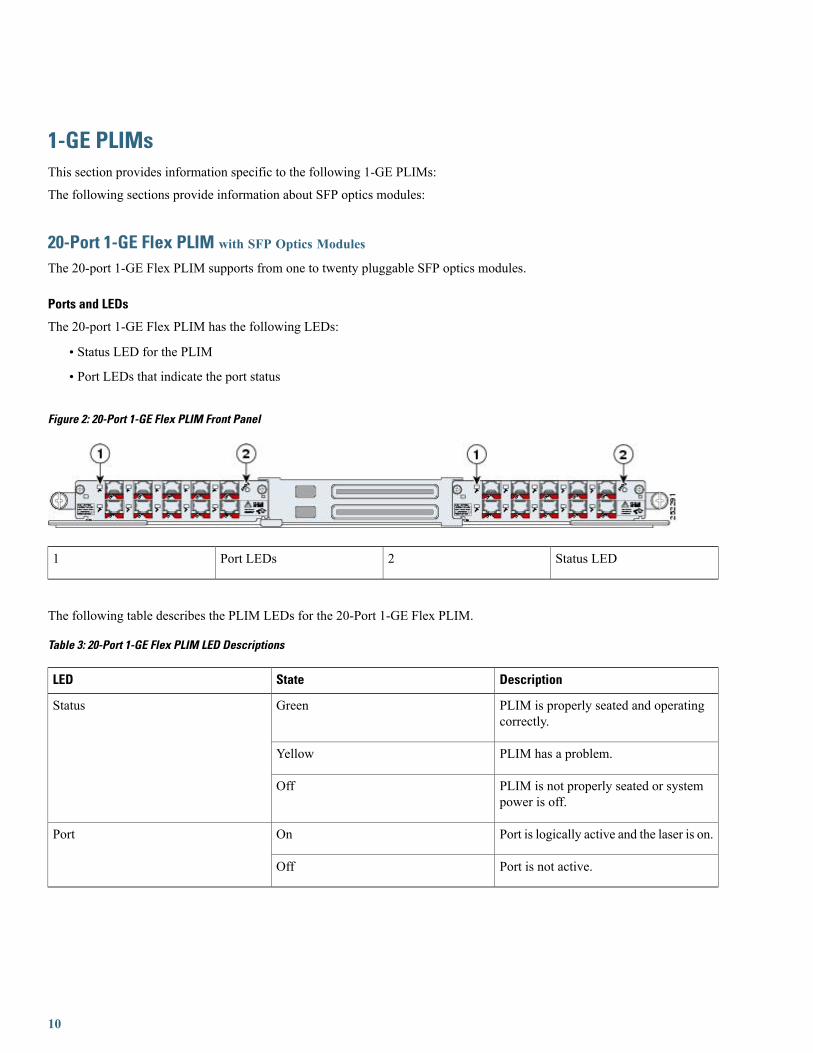
The 20-port 1-GE Flex PLIM supports from one to twenty pluggable SFP optics modules.
Ports and LEDs
The 20-port 1-GE Flex PLIM has the following LEDs:
• Status LED for the PLIM
• Port LEDs that indicate the port status
Figure 2: 20-Port 1-GE Flex PLIM Front Panel
Status LED2Port LEDs1
The following table describes the PLIM LEDs for the 20-Port 1-GE Flex PLIM.
Table 3: 20-Port 1-GE Flex PLIM LED Descriptions
DescriptionStateLED
PLIM is properly seated and operatingcorrectly.
GreenStatus
PLIM has a problem.Yellow
PLIM is not properly seated or systempower is off.
Off
Port is logically active and the laser is on.OnPort
Port is not active.Off
10

Physical Characteristics
• Height—20.6 in. (52.3 cm)
• Depth—11.2 in. (28.5 cm)
•Width—1.8 in. (4.6 cm)
•Weight—8.6 lb (3.9 kg)
• Power consumption—150 W
The 20-Port 1-GE Flex PLIM has twenty electrical connectors that support SFP modules. Each port can send and receive traffic usingcabling appropriate for the SFP module inserted.
20-Port 1-GE Flex PLIM SPA Support
The 20-Port 1-GE Flex PLIM provides 20 ports of IEEE 802.3-compliant GE interfaces and two available Cisco I-Flex shared portadapter (SPA) slots. These slots can support up to up to 2 additional half-height SPAs.
The SPAs supported in the two available Cisco I-Flex shared port adapter (SPA) slots can be Packet over SONET/SDH (PoS) orEthernet. The following SPAs are supported:
• SPA-5X1GE-V2
• SPA-8X1GE
• SPA-8X1GE-V2
• SPA-10X1GE-V2
• SPA-1X10GE-L-V2
• SPA-1X10GE-WL-V2
• SPA-4XOC3-POS
• SPA-8XOC12-POS
• SPA-2XOC48POS/RPR
• SPA-4XOC48POS/RPR
• SPA-OC192POS-VSR
• SPA-OC192POS-XFP
Refer to the Installing and Removing a Shared Port Adapter chapter of the Cisco CRS-1 SIP and SPA Hardware Installation Guideonline here: http://www.cisco.com/en/US/docs/interfaces_modules/shared_port_adapters/install_upgrade/crs/crs1/installation/guide/crsspain.html for instructions on replacing the SPAs.
Refer to the Overview: Cisco CRS-1 Shared Port Adapters chapter of the Cisco CRS-1 SIP and SPA Hardware Installation Guideonline here: http://www.cisco.com/en/US/docs/interfaces_modules/shared_port_adapters/install_upgrade/crs/crs1/installation/guide/crsspaov.html for descriptions of each of the supported SPAs.
42-Port 1-GE PLIM with SFP Optics Modules
• The 42-port 1-GE PLIM supports from one to forty two pluggable SFP optics modules.
11

Ports and LEDs
The 42-port 1-GE SFP PLIM has the following LEDs:
• Status LED for the PLIM
• Port LEDs that indicate the port status
Figure 3: 42-Port 1 GE SFP PLIM Front Panel
Status LED2Port LEDs1
The following table describes the PLIM LEDs for the 42-Port 1-GE SFP PLIM.
Table 4: 42-Port 1-GE PLIM LED Descriptions
DescriptionStateLED
PLIM is properly seated and operatingcorrectly.
GreenStatus
PLIM has a problem.Yellow
PLIM is not properly seated or systempower is off.
Off
Port is logically active and the laser is on.OnPort
Port is not active.Off
Physical Characteristics
• Height—20.6 in. (52.3 cm)
• Depth—11.2 in. (28.5 cm)
•Width—1.8 in. (4.6 cm)
•Weight—8.6 lb (3.9 kg)
• Power consumption—150 W
The interface connectors on the 42-port 1-GE SFP PLIM are eight individual fiber-optic receivers that support SFP modules. Eachport can send and receive traffic using the optical fiber connections.
12
SFP Module ConnectionsThe small form-factor pluggable (SFP) module is an input/output (I/O) device that plugs into the GE optical slots on the 20-Port 1-GEFlex PLIM or the 42-port 1-GE SFP PLIM, linking the port with a 1000BASE-X fiber-optic network.
The 20-Port 1-GE Flex PLIM and 42-port 1-GE SFP PLIM accept only the SFP modules listed as supported in this document. AnSFP module check is run every time an SFP is inserted, and only SFP modules that pass this check can be used by the 20-port 1-GEPLIM or the 42-port 1-GE SFP PLIM.
SFP modules exist for technologies other than GE and for products other than the 20-Port 1-GE Flex PLIM and the 42-port 1-GESFP PLIM. However, the information in this document pertains only to SFP modules that plug into the 20-Port 1-GE Flex PLIM or42-port 1-GE SFP PLIM ports.
The SFP module has a receiver port (RX) and a transmitter port (TX) that compose one optical interface.
Table 5: 20-Port and 42-Port GE SFP Module Options
DescriptionSFP ModuleSFP Module Product Number
Contains a Class 1 laser of 850 nm for1000BASE-SX (short-wavelength)applications.
Short wavelength (1000BASE-SX)SFP-GE-S
Contains a Class 1 laser of 1310 nm for1000BASE-LX/LH (long-wavelength)applications.
Long wavelength/long haul(1000BASE-LX/LH)
SFP-GE-L
Contains a Class 1 laser of 1550 nm for1000BASE-ZX (extended-wavelength)applications.
Extended wavelength (1000BASE-ZX)SFP-GE-Z
Table 6: 20-Port and 42-Port SFP Module Specifications
DescriptionSpecification
SFP-GE-S: 770 to 860SFP-GE-L: 1270 to 1355SFP-GE-Z:1500 to 1580
Wavelength (nm)
SFP-GE-S: 500m on 50/125micronMMF; 300m on 62.5/125micron MMFSFP-GE-L: 6.2 miles (10 km)SFP-GE-Z: 49.7miles (80 km)
MMF = Multimodefiber
Note
Cabling distance (maximum)
SFP-GE-S: 23 to 185 degrees F (–5 to 85 degrees C)SFP-GE-L:23 to 185 degrees F (–5 to 85 degrees C)SFP-GE-Z: 23 to 185degrees F (–5 to 85 degrees C)
Operating case temperature range
SFP-GE-S: –40 to 185 degrees F (–40 to 85 degreesC)SFP-GE-L: –40 to 185 degrees F (–40 to 85 degreesC)SFP-GE-Z: –40 to 185 degrees F (–40 to 85 degrees C)
Storage temperature range
13

DescriptionSpecification
SFP-GE-S: 3.1 to 3.5 VSFP-GE-L: 3.1 to 3.5 VSFP-GE-Z:3.1 to 3.5 V
Supply voltage range
SFP-GE-S Modules
The 1000BASE-SX (short-wavelength) module operates on standard multimode fiber-optic link spans of up to 500 m on 50/125micron MMF (multimode fiber) and 300 m on 62.5/125 micron MMF.
SFP-GE-L Modules
The 1000BASE-LX/LH (long-wavelength/long-haul) module interfaces fully comply with theIEEE 802.3z 1000BASE-LX standard.However, their higher optical quality allows them to reach 6.2 miles (10 km) over single-mode fiber (SMF) versus the 3.1 miles (5km) specified in the standard.
SFP-GE-Z Modules
The 1000BASE-ZX (extended-wavelength) module operates on ordinary single-mode fiber-optic link spans of up to 49.7 miles (80km). Link spans of up to 62.1 miles (100 km) are possible using premium single-mode fiber or dispersion-shifted single-mode fiber.(Premium single-mode fiber has a lower attenuation per unit length than ordinary single-mode fiber; dispersion-shifted single-modefiber has both lower attenuation and less dispersion.)
The 1000BASE-ZX module must be coupled to single-mode fiber-optic cable, which is the type of cable typically used in long-haultelecommunications applications. The 1000BASE-ZX module does not operate correctly when coupled to multimode fiber, and it isnot intended to be used in environments in which multimode fiber is frequently used (for example, building backbones or horizontalcabling).
The 1000BASE-ZX module is intended to be used as a Physical Medium Dependent (PMD) component for GE interfaces found onvarious switch and router products. It operates at a signaling rate of 1250 Mbaud, transmitting and receiving 8B/10B encoded data.
When shorter lengths of single-mode fiber are used, it may be necessary to insert an inline optical attenuator in the link to avoidoverloading the receiver. Use the following guidelines:
• Insert a 10-dB inline optical attenuator between the fiber-optic cable plant and the receiving port on the 1000BASE-ZXmoduleat each end of the link whenever the fiber-optic cable span is less than 15.5 miles (25 km).
• Insert a 5-dB inline optical attenuator between the fiber-optic cable plant and the receiving port on the 1000BASE-ZX moduleat each end of the link whenever the fiber-optic cable span is equal to or greater than 15.5 miles (25 km) but less than 31 miles(50 km).
SFP Module Cabling and Connection EquipmentThe following table provides cabling specifications for the SFP modules that can be installed on the 20-Port 1-GE Flex PLIM andthe 42-port 1-GE SFP PLIM. Note that all SFP ports have LC-type connectors.
The minimum cable distance for the SFP-GE-S is 6.5 feet (2 m), and the minimum link distance for the SFP-GE-Z is 6.2 miles (10km) with an 8-dB attenuator installed at each end of the link. Without attenuators, the minimum link distance for the SFP-GE-Z is24.9 miles (40 km).
14

Table 7: SFP Module Port Cabling Specifications for the 20-Port 1-GE Flex PLIM
MaximumCableDistance
ModalBandwidth(MHz/km)
CoreSize(micron)
FiberType
Wavelength(nm)
SFPModules
722ft(220m)
16062.5MMF
Multimodefiberonly.
Note
850SFP-GE-S
984ft(300m)
20062.5
1640ft(500m)
40050.0
1804ft(550m)
50050.0
6.2miles(10km)
—9/10SMF1300SFP-GE-L
49.7miles(80km)
—9/10SMF1500SFP-GE-Z
62.1miles(100km)
—8SMF
Dispersion-shiftedsingle-modefiber-opticcable.
Note
15

Table 8: SFP Module Port Cabling Specifications for the 42-Port 1-GE SFP PLIM
MaximumCableDistance
Modal Bandwidth(MHz/km)
Core Size (micron)Fiber TypeWavelength (nm)SFP Modules
722 ft (220 m)16062.5MMF
Multimodefiber(MMF)only.
Note
850SFP-GE-S
984 ft (300 m)20062.5
1640 ft (500 m)40050.0
1804 ft (550 m)50050.0
1804 ft (550 m)50062.5MMF and SMF
Amode-conditioningpatch cord isrequired.Whenusing theSFP-GE-Lwith62.5-microndiameterMMF,youmust installamode-conditioningpatch cordbetween theSFP moduleand the MMFcable on boththe transmitand the receiveends of the linkwhen linkdistances aregreater than984 ft (300m).We do notrecommendusing theSFP-GE-L andMMF with nopatch cord forvery short linkdistance (tensof meters). Theresult could bean elevated biterror rate(BER).
Note
1300SFP-GE-L
1804 ft (550 m)40050.0
1804 ft (550 m)50050.0
6.2 miles (10 km)—9/10
16

MaximumCableDistance
Modal Bandwidth(MHz/km)
Core Size (micron)Fiber TypeWavelength (nm)SFP Modules
49.7 miles (80 km)—9/10SMF1550SFP-GE-Z
62.1 miles (100km)
—8SMF
Dispersion-shiftedsingle-modefiber-opticcable.
Note
The 1000BASE-ZX SFP modules provide an optical power budget of 21.5 dB. You should measure yourcable plant with an optical loss test set to verify that the optical loss of the cable plant (including connectorsand splices) is less than or equal to 21.5 dB. The optical loss measurement must be performed with a1550-nm light source.
Note
Installing and Removing SFP ModulesBefore you remove or install an SFP module, read the installation information in this section and the safety information in the LaserSafety, on page 112 section.
Protect the SFP modules by inserting clean dust covers into them after the cables are removed. Be sureto clean the optic surfaces of the fiber cables before you plug them back into the optical ports of anothermodule. Avoid getting dust and other contaminants into the optical ports of your SFP modules, becausethe optics do not work correctly when obstructed with dust.
Caution
It is strongly recommended that you do not install or remove the SFP module with fiber-optic cablesattached to it because of the potential to damage the cable, the cable connector, or the optical interfacesin the module. Disconnect all cables before removing or installing the SFPmodule.Removing and insertingan module can shorten its useful life, so you should not remove and insert modules any more often thanis absolutely necessary.
Caution
SFP modules use one of four different latching devices to install and remove the module from a port. The four types of SFP modulelatching devices are described in the following sections:
When installing the SFP module, you should hear a click as the triangular pin on the bottom of the modulesnaps into the hole in the receptacle, indicating that the module is correctly seated and secured in thereceptacle. Verify that the modules are completely seated and secured in their assigned receptacles on theline card by firmly pushing on each SFP module.
Note
17

Bail Clasp SFP Module
The bail clasp SFP module has a clasp that you use to remove or install the module (see the following figure).
Figure 4: Bail Clasp SFP Module
Installing a Bail Clasp SFP ModuleTo install this type of SFP module, follow these steps:
Procedure
Step 1 Attach an ESD-preventive wrist or ankle strap and follow its instructions for use.Step 2 Close the bail clasp before inserting the SFP module.Step 3 Line up the SFP module with the port and slide it into the port (see the following figure).
Figure 5: Installing a Bail Clasp SFP Module into a Port
18

What to Do Next
When installing an SFP module, you should hear a click as the triangular pin on the bottom of the SFPmodule snaps into the hole in the receptacle, indicating that the module is correctly seated and secured inthe receptacle. Verify that the SFPmodules are completely seated and secured in their assigned receptacleson the line card by firmly pushing on each SFP module.
Note
Removing a Bail Clasp SFP ModuleTo remove this type of SFP module, follow these steps:
Procedure
Step 1 Attach an ESD-preventive wrist or ankle strap and follow its instructions for use.Step 2 Disconnect and remove all interface cables from the ports; note the current connections of the cables to the ports on the
line card.Step 3 Open the bail clasp on the SFP module with your index finger in a downward direction, as shown in the following figure.
If the bail clasp is obstructed and you cannot use your index finger to open it, use a small flat-blade screwdriver or otherlong, narrow instrument to open the bail clasp.
Step 4 Grasp the SFPmodule between your thumb and index finger and carefully remove it from the port, as shown in the followingfigure.
19

Figure 6: Removing a Bail Clasp SFP Module
Step 5 Place the removed SFP module on an antistatic mat, or immediately place it in a static shielding bag if you plan to returnit to the factory.
Step 6 Protect your line card by inserting clean SFPmodule cage covers into the optical module cage when there is no SFPmoduleinstalled.
20

Mylar Tab SFP Module
The mylar tab SFP module has a tab to pull to remove the module from a port (see the following figure).
Figure 7: Mylar Tab SFP Module
Installing a Mylar Tab SFP ModuleTo install this type of SFP module, follow these steps:
Procedure
Step 1 Attach an ESD-preventive wrist or ankle strap and follow its instructions for use.Step 2 Line up the SFP module with the port, and slide it into place (see the following figure).
Figure 8: Installing a Mylar Tab SFP Module
21

What to Do Next
When installing an SFP module, you should hear a click as the triangular pin on the bottom of the SFPmodule snaps into the hole in the receptacle, indicating that the module is correctly seated and secured inthe receptacle. Verify that the SFPmodules are completely seated and secured in their assigned receptacleson the line card by firmly pushing on each SFP module.
Note
Removing a Mylar Tab SFP ModuleTo remove this type of SFP module, follow these steps:
Procedure
Step 1 Attach an ESD-preventive wrist or ankle strap and follow its instructions for use.Step 2 Disconnect and remove all interface cables from the ports; note the current connections of the cables to the ports on the
line card.Step 3 Pull the tab gently in a slightly downward direction until it disengages from the port, then pull the SFP module out (see
the following figure).
Figure 9: Removing a Mylar Tab SFP Module
Step 4 Place the removed SFP module on an antistatic mat, or immediately place it in a static shielding bag if you plan to returnit to the factory.
Step 5 Protect your line card by inserting clean SFPmodule cage covers into the optical module cage when there is no SFPmoduleinstalled.
22
What to Do Next
When pulling the tab to remove the SFP module, be sure to pull in a straight outward motion so you remove the SFP module fromthe port in a parallel direction. Do not twist or pull the tab, because you might disconnect it from the SFP module.
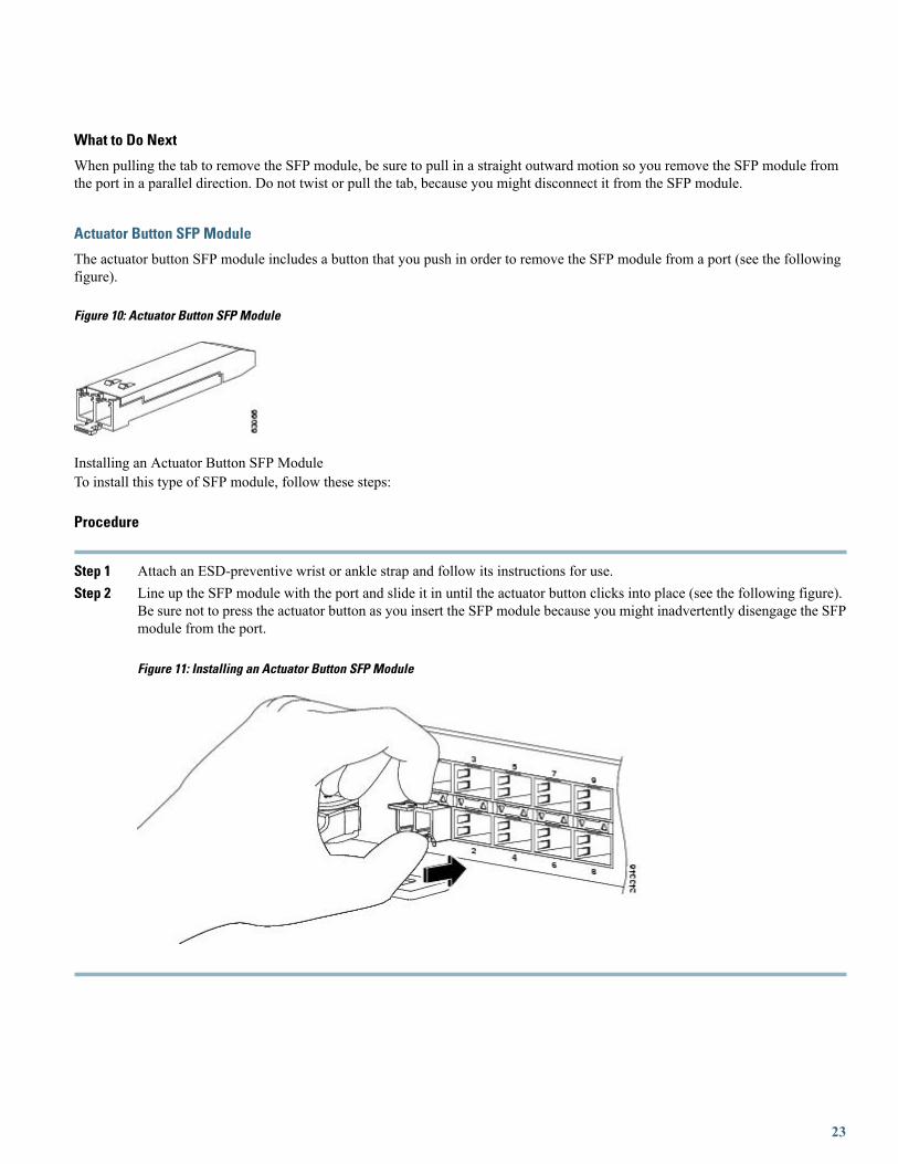
Actuator Button SFP Module
The actuator button SFP module includes a button that you push in order to remove the SFP module from a port (see the followingfigure).
Figure 10: Actuator Button SFP Module
Installing an Actuator Button SFP ModuleTo install this type of SFP module, follow these steps:
Procedure
Step 1 Attach an ESD-preventive wrist or ankle strap and follow its instructions for use.Step 2 Line up the SFP module with the port and slide it in until the actuator button clicks into place (see the following figure).
Be sure not to press the actuator button as you insert the SFP module because you might inadvertently disengage the SFPmodule from the port.
Figure 11: Installing an Actuator Button SFP Module
23

What to Do Next
When installing an SFP module, you should hear a click as the triangular pin on the bottom of the SFPmodule snaps into the hole in the receptacle, indicating that the module is correctly seated and secured inthe receptacle. Verify that the SFPmodules are completely seated and secured in their assigned receptacleson the line card by firmly pushing on each SFP module.
Note
Removing an Actuator Button SFP ModuleTo remove this type of SFP module, follow these steps:
Procedure
Step 1 Attach an ESD-preventive wrist or ankle strap and follow its instructions for use.Step 2 Disconnect and remove all interface cables from the ports; note the current connections of the cables to the ports on the
line card.Step 3 Gently press the actuator button on the front of the SFP module until it clicks and the latch mechanism activates, releasing
the SFP module from the port (see the following figure).
24

Figure 12: Removing an Actuator Button SFP Module from a Port
Step 4 Grasp the actuator button between your thumb and index finger and carefully pull the SFP module from the port.Step 5 Place the removed SFP module on an antistatic mat, or immediately place it in a static shielding bag if you plan to return
it to the factory.Step 6 Protect your line card by inserting clean SFPmodule cage covers into the optical module cage when there is no SFPmodule
installed.
25

Slide Tab SFP Module
The slide tab SFP module has a tab underneath the front of the module that you use to disengage the module from a port (see thefollowing figure).
Figure 13: Slide Tab SFP Module
Installing a Slide Tab SFP ModuleTo install this type of SFP module into a line card, follow these steps:
Procedure
Step 1 Attach an ESD-preventive wrist or ankle strap and follow its instructions for use.Step 2 Line up the SFP module with the port and gently push on it until it snaps into the slot tightly (see the following figure).
Figure 14: Installing a Slide Tab SFP Module
26
What to Do Next
When installing an SFP module, you should hear a click as the triangular pin on the bottom of the SFPmodule snaps into the hole in the receptacle, indicating that the module is correctly seated and secured inthe receptacle. Verify that the SFPmodules are completely seated and secured in their assigned receptacleson the line card by firmly pushing on each SFP module.
Note
Removing a Slide Tab SFP ModuleTo remove this type of SFP module, follow these steps:
Procedure
Step 1 Attach an ESD-preventive wrist or ankle strap and follow its instructions for use.Step 2 Disconnect and remove all interface cables from the ports; note the current connections of the cables to the ports on the
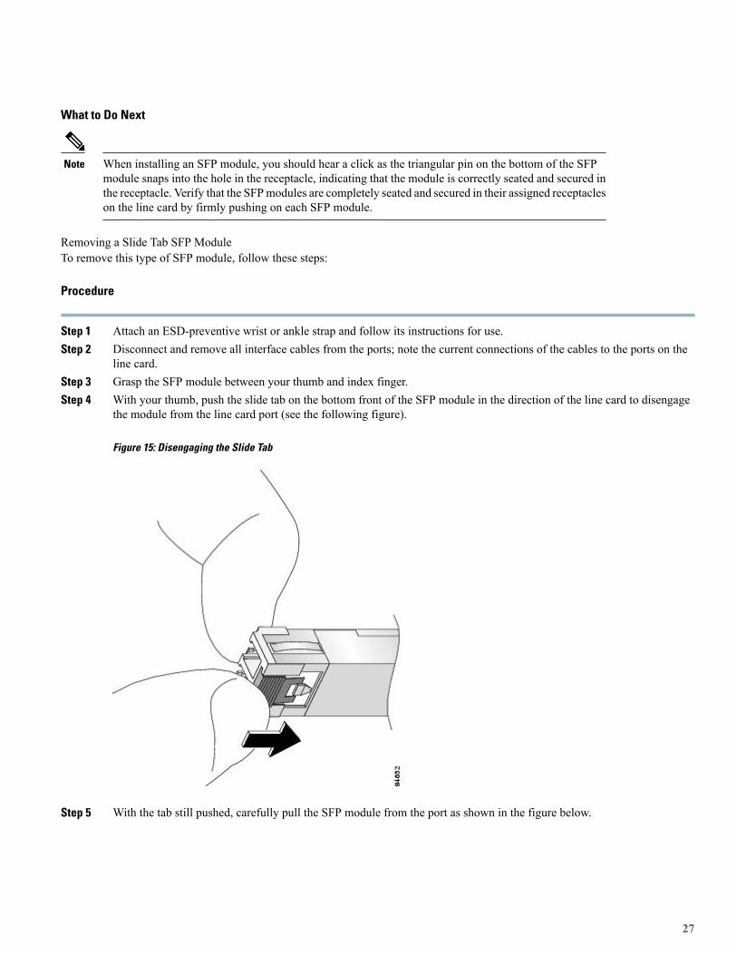
line card.Step 3 Grasp the SFP module between your thumb and index finger.Step 4 With your thumb, push the slide tab on the bottom front of the SFP module in the direction of the line card to disengage
the module from the line card port (see the following figure).
Figure 15: Disengaging the Slide Tab
Step 5 With the tab still pushed, carefully pull the SFP module from the port as shown in the figure below.
27

You must disengage the SFP module by pushing on the slide tab before you can pull out the module. If youpull on the SFP module without disengaging the tab, you can damage the module.
Caution
Figure 16: Removing a Slide Tab SFP Module
Step 6 Place the removed SFP module on an antistatic mat, or immediately place it in a static shielding bag if you plan to returnit to the factory.
Step 7 Protect your line card by inserting clean SFPmodule cage covers into the optical module cage when there is no SFPmoduleinstalled.
Replacing a SFP on a Line Card that Uses an Articulated BracketTo replace a failed, defective, or retired SFP from a line card that is currently in service, and using an articulated cable managementbracket, proceed as follows:
Procedure
Step 1 For a line card with multiple articulated brackets, select the fibers to be removed from the bracket with the SFP to beremoved.For a line card with a single articulated bracket, begin with Step 2.
Step 2 Undo and remove the Velcro from the articulated bracket to release the fibers.Step 3 From the physical location of the SFP to be removed, determine which end of the articulated bracket will be unscrewed:
• For the upper half of the line card, remove the top screw.
• For the lower half of the line card, remove the lower screw.
• If there is any interference with another installed bracket, choose the other screw location.
28

Step 4 Pivot the articulated bracket up or down, depending on which screw was removed.Step 5 Label and disconnect the fibers from the port and put them aside.Step 6 Remove the SFP.Step 7 Replace with the new SFP (or a dust cap if the port is not going to be reused).Step 8 Re-install the fibers that were removed in Step 5. per the labels.Step 9 Pivot the articulated bracket back into position and secure.Step 10 Re-dress and secure the fibers to the articulated bracket with Velcro.
10-GE PLIMsThis section provides information specific to the following 10-GE PLIMs:
The following sections provide information about optics modules:
2-Port 10-GE Flex PLIM with XFP Optics ModulesThe 2-port 10-GE Flex PLIM supports from one to two pluggable XFP optics modules.
Supported XFP Optics Modules
• Single-mode short reach (SR) XFP module—XFP-10GLR-OC192SR
• Single-mode intermediate reach (IR) XFP module—XFP-10GER-OC192IR
• Single-mode very-long reach (ZR) XFP module—XFP-10GZR-OC192LR
Cisco qualifies the optics that are approved for use with its PLIMs.
Use a single-mode optical fiber that has a modal-field diameter of 8.7 ±0.5 microns (nominal diameter is approximately 10/125micron) to connect your router to a network.
Ports and LEDs
The 2-port 10-GE Flex PLIM has:
• Two ports that accept XFP optics modules
• Status LED for the PLIM
• Port status LED for each port
29

The following figure shows shows the front panel of the 2-port 10-GE Flex PLIM.
Figure 17: 2-Port 10-GE Flex PLIM front panel
PLIM Status LED2Port Status LED1
The following table describes the PLIM LEDs for the 2-port 10-GE Flex PLIM.
Table 9: 2-Port 10-GE Flex PLIM LED Descriptions
DescriptionStateLED
PLIM is properly seated and operatingcorrectly.
GreenPLIM Status
PLIM has a problem.Yellow
PLIM is not properly seated or systempower is off.
Off
Port is logically active and the laser is on.OnPort Status
Port is not active.Off
Physical Characteristics
• Height—20.6 in. (52.3 cm)
• Depth—11.2 in. (28.5 cm)
•Width—1.8 in. (4.6 cm)
•Weight—8.4 lb (3.8 kg)
• Power consumption—33 W (with two optics modules)
2-Port 10-GE Flex PLIM SPA Support
The 2-Port 10-GE Flex PLIM provides two ports of IEEE 802.3ae-compliant 10 GEWAN/LAN-physical (PHY) layer interfaces andtwo available Cisco I-Flex shared port adapter (SPA) slots. These slots can support up to up to 2 additional half-height SPAs.
The SPAs supported in the two available Cisco I-Flex shared port adapter (SPA) slots can be Packet over SONET/SDH (PoS) orEthernet. The following SPAs are supported:
30

• SPA-5X1GE-V2
• SPA-8X1GE
• SPA-8X1GE-V2
• SPA-10X1GE-V2
• SPA-1X10GE-L-V2
• SPA-1X10GE-WL-V2
• SPA-4XOC3-POS
• SPA-8XOC12-POS
• SPA-2XOC48POS/RPR
• SPA-4XOC48POS/RPR
• SPA-OC192POS-VSR
• SPA-OC192POS-XFP
Refer to the Installing and Removing a Shared Port Adapter chapter of the Cisco CRS-1 SIP and SPA Hardware Installation Guideonline here: http://www.cisco.com/en/US/docs/interfaces_modules/shared_port_adapters/install_upgrade/crs/crs1/installation/guide/crsspain.html for instructions on replacing the SPAs.
Refer to the Overview: Cisco CRS-1 Shared Port Adapters chapter of the Cisco CRS-1 SIP and SPA Hardware Installation Guideonline here: http://www.cisco.com/en/US/docs/interfaces_modules/shared_port_adapters/install_upgrade/crs/crs1/installation/guide/crsspaov.html for descriptions of each of the supported SPAs.
4-Port 10-GE PLIM with XENPAK Optics ModulesThe 4-port 10-GE PLIM supports from one to four pluggable XENPAK optics modules, each providing full-duplex long-wavelengthor extra-long-wavelength optics with subscriber connector (SC) fiber-optic interfaces.
Ports and LEDs
The 4-port 10-GE PLIM has:
• Four ports that accept XENPAK optics modules
• Status LED for the PLIM
• Port status LED for each port
The following figure shows the front panel of the 4-port 10-GE PLIM.
Figure 18: 4-Port 10-GE PLIM front panel
31
Status LED1
The following table describes the PLIM LEDs for the 4-Port 10-GE XENPAK PLIM.
Table 10: 4-Port 10-GE PLIM LED Descriptions
DescriptionStateLED
PLIM is properly seated and operatingcorrectly.
GreenPLIM Status
PLIM has a problem.Yellow
PLIM is not properly seated or systempower is off.
Off
Port is logically active and the laser is on.OnPort Status
Port is not active.Off
Physical Characteristics
• Height—20.6 in. (52.3 cm)
• Depth—11.2 in. (28.5 cm)
•Width—1.8 in. (4.6 cm)
•Weight—8.4 lb (3.8 kg)
• Power consumption—75 W (with four optics modules)
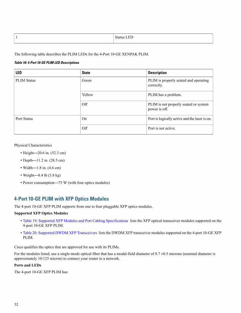
4-Port 10-GE PLIM with XFP Optics ModulesThe 4-port 10-GE XFP PLIM supports from one to four pluggable XFP optics modules.
Supported XFP Optics Modules
• Table 19: Supported XFP Modules and Port Cabling Specifications lists the XFP optical transceiver modules supported on the4-port 10-GE XFP PLIM.
• Table 20: Supported DWDMXFP Transceivers lists the DWDMXFP transceiver modules supported on the 4-port 10-GE XFPPLIM.
Cisco qualifies the optics that are approved for use with its PLIMs.
For the modules listed, use a single-mode optical fiber that has a modal-field diameter of 8.7 ±0.5 microns (nominal diameter isapproximately 10/125 micron) to connect your router to a network.
Ports and LEDs
The 4-port 10-GE XFP PLIM has:
32

• Four ports that accept XFP optics modules
• Status LED for the PLIM
• LED for each port
The following figure shows the front panel of the 4-Port 10-GE XFP PLIM.
Figure 19: 4-Port 10-GE XFP PLIM front panel
Status LED2Port LED (one per port)1
The following table describes the PLIM LEDs for the 4-Port 10-GE XFP PLIM.
Table 11: 4-Port 10-GE XFP PLIM LED Descriptions
DescriptionStateLED
PLIM is properly seated and operatingcorrectly.
GreenStatus
PLIM has a problem.Yellow
PLIM is not properly seated or systempower is off.
Off
Port is enabled by software and there isa valid link.
GreenPort
Port LED is yellow under all otherconditions not covered by green LEDstatus.
Yellow
PLIM is not properly seated or systempower is off.
Off
Physical Characteristics
• Height—20.6 in. (52.3 cm)
• Depth—11.2 in. (28.5 cm)
•Width—1.8 in. (4.6 cm)
33

•Weight—8.4 lb (3.8 kg)
• Power consumption—74 W (with four optics modules)
8-Port 10-GE PLIM with XENPAK Optics ModulesThe 8-port 10-GE PLIM supports from one to eight pluggable XENPAK optics modules, each providing full-duplex long-wavelengthor extra-long-wavelength optics with subscriber connector (SC) fiber-optic interfaces. This PLIM is a Class 1 laser product.
Class 1 Laser Product. Statement 1008Warning
Ports and LEDs
The 8-port 10-GE XENPAK PLIM has:
• Eight ports that accept XENPAK optics modules
• Status LED for the PLIM
• Port status LED for each port
34

The following figure shows the front panel of the 8-port 10-GE PLIM.
Figure 20: 8-Port 10-GE PLIM Front Panel
PLIM Status LED2Port 1 Status LED1
The following table describes the PLIM LEDs for the 8-Port 10-GE PLIM.
35

Table 12: 8-Port 10-GE PLIM LED Descriptions
DescriptionStateLED
PLIM is properly seated and operatingcorrectly.
GreenPLIM Status
PLIM has a problem.Yellow
PLIM is not properly seated or systempower is off.
Off
Port is logically active and the laser is on.OnPort Status
Port is not active.Off
Physical Characteristics
• Height—20.6 in. (52.3 cm)
• Depth—11.2 in. (28.5 cm)
•Width—1.8 in. (4.6 cm)
•Weight—8.4 lb (3.8 kg)
• Power consumption—150 W (with eight optics modules)
Oversubscription of 10-GE Ports
Processing on the 10-GE PLIM is performed by two PLIM hardware controllers, each of which can process up to 24 Gbps of traffic.Ports 0 to 3 are associated with one PLIM hardware controller, while ports 4 to 7 are associated with the second PLIM hardwarecontroller. In addition, the PLIM ports are serviced by twoMSC hardware controllers, the switching capacity of which is approximately62 Mpps (million packets per second) each. Each MSC hardware controller is statically assigned to four of the eight ports.
Because of this PLIM design, the placement of the optics modules in the PLIM can greatly affect whether or not oversubscriptionoccurs. For example, if modules are installed in ports 0 and 1, each interface has 10 Gbps of throughput. Adding another module inport 2 causes oversubscription on all interfaces (0, 1, and 2).
If your configuration cannot support oversubscription, use the following guidelines to determine the PLIM ports in which to installoptics modules:
• Do not install more than four optics modules in each PLIM.
• Use the following port arrangements to provide optimal performance for up to four 10-GE interfaces in a 10-GE PLIM:
Port Numbers
7520Option 1
6444Option 2
36

If your configuration can support oversubscription and you want to install more than four optics modules in a PLIM, we recommendthat you install additional modules in empty ports, alternating between upper and lower ports and odd and even ports. For example,if you install a fifth optics module in an odd port in the upper set of ports (0 to 3), be sure to install the next module in an even portin the lower set of ports (4 to 7), and so on.
8-Port 10-GE PLIM with XFP Optics ModulesThe 8-port 10-GE XFP PLIM supports from one to eight pluggable XFP optics modules.
Supported XFP Optics Modules
• Table 19: Supported XFP Modules and Port Cabling Specifications lists the XFP optical transceiver modules supported on the8-port 10-GE XFP PLIM.
• Table 20: Supported DWDMXFP Transceivers lists the DWDMXFP transceiver modules supported on the 8-port 10-GE XFPPLIM.
Cisco qualifies the optics that are approved for use with its PLIMs.
For the modules listed, use a single-mode optical fiber that has a modal-field diameter of 8.7 ±0.5 microns (nominal diameter isapproximately 10/125 micron) to connect your router to a network.
Ports and LEDs
The 8-port 10-GE XFP PLIM has:
• Eight ports that accept XFP optics modules
• Status LED for the PLIM
• LED for each port
The following figure shows the front panel of the 8-Port 10-GE XFP PLIM.
Figure 21: 8-Port 10-GE XFP PLIM front panel
Status LED2Port LED (one per port)1
The following table describes the PLIM LEDs for the 8-Port 10-GE XFP PLIM.
37

Table 13: 8-Port 10-GE XFP PLIM LED Descriptions
DescriptionStateLED
PLIM is properly seated and operatingcorrectly.
GreenStatus
PLIM has a problem.Yellow
PLIM is not properly seated or systempower is off.
Off
Port is enabled by software and there isa valid link.
GreenPort
Port LED is yellow under all otherconditions not covered by green LEDstatus.
Yellow
PLIM is not properly seated or systempower is off.
Off
Physical Characteristics
• Height—20.6 in. (52.3 cm)
• Depth—11.2 in. (28.5 cm)
•Width—1.8 in. (4.6 cm)
•Weight—8.4 lb (3.8 kg)
• Power consumption—88 W (with eight optics modules)
14-Port 10-GE PLIM with XFP Optics ModulesThe 14-port 10-GE XFP PLIM supports from one to fourteen pluggable XFP optics modules.
Supported XFP Optics Modules
Table 19: Supported XFPModules and Port Cabling Specifications lists the XFP optical transceiver modules supported on the 14-port10-GE XFP PLIM. Table 20: Supported DWDM XFP Transceivers lists the DWDM XFP transceiver modules supported on the14-port 10-GE XFP PLIM.
Cisco qualifies the optics that are approved for use with its PLIMs.
The 14-port XFP PLIM has a fixed power budget for the pluggable XFP optics. See XFP Optics PowerManagement, on page 48 section for detailed information.
Note
For the modules listed, use a single-mode optical fiber that has a modal-field diameter of 8.7 ±0.5 microns (nominal diameter isapproximately 10/125 micron) to connect your router to a network. The following figure shows the front panel of the 14-Port 10-GEXFP PLIMs.
38

Ports and LEDs
The 14-port 10-GE XFP PLIM has:
• Fourteen ports that accept XFP optics modules
• Status LED for the PLIM
• LED for each port
Figure 22: 14-Port 10-GE XFP PLIM front panel
Status LED2Port LED (one per port)1
The following table describes the PLIM LEDs for the 14-Port 10-GE XFP PLIM.
Table 14: 14-Port 10-GE XFP PLIM LED Descriptions
DescriptionStateLED
PLIM is properly seated and operatingcorrectly.
GreenPLIM Status
PLIM is powered on, but initializing.Yellow
PLIM is not properly seated, systempower is off, or power up did notcomplete successfully.
Off
Port is enabled by software and there isa valid link.
GreenPort
Port LED is yellow under all otherconditions not covered by green LEDstatus.
Yellow
PLIM is not properly seated or systempower is off.
Off
Physical Characteristics
• Height—20.6 in (52.2 cm)
• Depth—11.2 in (28.4 cm)
39

•Width—1.8 in (4.49 cm)
•Weight—7.85 lbs (3.55 kg)
• Power consumption—150 W (115 W with no optics installed, 35 W optics budget)
20-Port 10-GE PLIM with XFP Optics ModulesThe 20-port 10-GE XFP PLIM supports from one to twenty pluggable XFP optics modules.
Supported XFP Optics Modules
Table 19: Supported XFPModules and Port Cabling Specifications lists the XFP optical transceiver modules supported on the 20-port10-GE XFP PLIM. Table 20: Supported DWDM XFP Transceivers lists the DWDM XFP transceiver modules supported on the20-port 10-GE XFP PLIM.
Cisco qualifies the optics that are approved for use with its PLIMs.
The 20-port XFP PLIM has a fixed power budget for the pluggable XFP optics. See XFP Optics PowerManagement, on page 48 section for detailed information.
Note
For the modules listed, use a single-mode optical fiber that has a modal-field diameter of 8.7 ±0.5 microns (nominal diameter isapproximately 10/125 micron) to connect your router to a network.
Ports and LEDs
The 20-port 10-GE XFP PLIM has:
• Twenty ports that accept XFP optics modules
• Status LED for the PLIM
• Port status LED for each port
The following figure shows the front panel of the 20-Port 10-GE XFP PLIMs.
Figure 23: 20-Port 10-GE XFP PLIM front panel
Status LED2Port LED (one per port)1
The following table describes the PLIM LEDs for the 20-Port 10-GE XFP PLIM.
40

Table 15: 20-Port 10-GE XFP PLIM LED Descriptions
DescriptionStateLED
PLIM is properly seated and operatingcorrectly.
GreenPLIM Status
PLIM is powered on, but initializing.Yellow
PLIM is not properly seated, systempower is off, or power up did notcomplete successfully.
Off
Port is enabled by software and there isa valid link.
GreenPort
Port LED is yellow under all otherconditions not covered by green LEDstatus.
Yellow
PLIM is not properly seated or systempower is off.
Off
Physical Characteristics
• Height—20.6 in (52.2 cm)
• Depth—11.2 in (28.4 cm)
•Width—1.8 in (4.49 cm)
•Weight—8.45 lb (3.82 kg)
• Power consumption—150 W (120 W with no optics installed, 30 W optics budget)
40-Port 10-GE PLIM with SFP+ Optics Modules
In the enhanced chassis, all 40 ports of this PLIM can be used. In the legacy chassis, this PLIM is operatedin 200G mode as a 20-port 10-GE SFP+ PLIM. In this case, only the 20 ports on the right are enabled.
Note
The 40-port 10-GE SFP+ PLIM supports from one to forty pluggable SFP+ optics modules.
For more information about SFP+ optics modules, see SFP+ Module Connections, on page 52 and SFP+Module Cabling and Connection Equipment, on page 55.
Note
Ports and LEDs
The 40-port 10-GE SFP+ PLIM has:
• Forty ports that accept SFP+ optics modules
41

• Status LED for the PLIM
• Port status LED for each port
For this PLIM, a time interval of three seconds is required after removing, and before re-inserting theSFP+ optics modules.
Note
The following figure shows the front panel of the 40-Port 10-GE SFP+ PLIMs.
Figure 24: 40-Port 10-GE SFP+ PLIM front panel
Status LED2Port LED (one per port)1
The 40-Port 10-GE PLIM comprises two sets of twenty ports, each of which are connected to a dedicated Network Processor. Whenoperated in the legacy chassis, the PLIM operates in 200G mode, in which the top set of ports and their Network Processor aredeactivated due to thermal constraints. In 200G mode, the port numbering will be different than 400G mode and will start with 0 forthe port that is labeled 20 in 400G mode. The faceplate labels therefore include two port numbers for the ports that are active in 200GMode, as shown in the following figure.
Figure 25: Half of the Front Panel, Showing Two Sets of Port Numbers
In the enhanced chassis, the 40-Port 10-GE PLIMmay optionally operate in Green mode, in which twenty of the ports are deactivated(using the CLI) to save power. In Green mode, the port numbering follows the 400G mode model, which results in only ports 20-39being active. Ports 0-19 will not be visible in the CLI when the card is in Green mode. Therefore, the port numbers for ports used inGreen mode will not change when the card is converted to 400G mode.
The following table describes the PLIM LEDs for the 40-Port 10-GE SFP+ PLIM.
42

Table 16: 40-Port 10-GE SFP+ PLIM LED Descriptions
DescriptionStateLED
PLIM is properly seated and operatingcorrectly.
GreenPLIM Status
PLIM is powered on, but initializing.Yellow
PLIM is not properly seated, systempower is off, or power up did notcomplete successfully.
Off
Port is enabled by software and there isa valid link.
GreenPort
Port LED is yellow under all otherconditions not covered by green LEDstatus.
Yellow
PLIM is not properly seated or systempower is off.
Off
Physical Characteristics
• Height—20.6 in (52.2 cm)
• Depth—11.2 in (28.4 cm)
•Width—1.8 in (4.49 cm)
•Weight—7.55 lbs (3.55 kg)
• Power consumption—110 W
In Cisco IOSXRRelease 5.3.2 or earlier versions, High-powered optics such as SFP-10G-ER, SFP-10G-ZRand DWDM can only be inserted in ports 30-39 of the PLIM. These high-powered optics if inserted inports 0-29, can cause a boot failure.
Note
In Cisco IOSXRRelease 6.0.1 and later versions, up to 30 high-powered optics on the PLIM are supported.Only 15 high-power optics each can be inserted in 0-19 ports (upper slice) and 20-39 ports (lower slice).The low power optics can be inserted in any of the remaining ports. Users cannot insert more than 15high-power optics in a given slice.
Note
43

10-GE PLIM with DWDM XENPAK ModulesIn addition to 10-GEmodules, the 10-GE PLIM supports from one to four pluggable dense wavelength-divisionmultiplexing (DWDM)XENPAK optics modules, each providing full-duplex long-wavelength DWDM optics with SC fiber-optic interfaces. See the 8-Port10-GE PLIM with XENPAK Optics Modules , on page 34 section for general information about the PLIM.
When using DWDM optics modules on your 10-GE PLIM, an empty slot must exist next to each installed DWDMmodule to provideoptimal cooling for the DWDM optics. For this reason, you can install up to four DWDM XENPAK modules in the 10-GE PLIM.Given this restriction and to optimize the PLIM for oversubscription, you should use port positions 0, 2, 5, and 7.
One to four DWDM XENPAK modules can be installed. If one DWDM XENPAK module is installed,a maximum of four XENPAK modules can be installed in the PLIM.
Caution
The following table lists the part numbers and frequencies of the DWDM XENPAK optics modules that are compatible with the10-GE PLIM.
Table 17: DWDM XENPAK Optics Modules
Center Wavelength (nm)Frequency (THz)Part Numbernm =nanometers
Note
1530.33195.9DWDM-XENPAK-30.33
1531.12195.8DWDM-XENPAK-31.12
1531.90195.7DWDM-XENPAK-31.90
1532.68195.6DWDM-XENPAK-32.68
1534.25195.4DWDM-XENPAK-34.25
1535.04195.3DWDM-XENPAK-35.04
1535.82195.2DWDM-XENPAK-35.82
1536.61195.1DWDM-XENPAK-36.61
1538.19194.9DWDM-XENPAK-38.19
1538.98194.8DWDM-XENPAK-38.98
1539.77194.7DWDM-XENPAK-39.77
1540.56194.6DWDM-XENPAK-40.56
1542.14194.4DWDM-XENPAK-42.14
1542.94194.3DWDM-XENPAK-42.94
44

Center Wavelength (nm)Frequency (THz)Part Numbernm =nanometers
Note
1543.73194.2DWDM-XENPAK-43.73
1544.53194.1DWDM-XENPAK-44.53
1546.12193.9DWDM-XENPAK-46.12
1546.92193.8DWDM-XENPAK-46.92
1547.72193.7DWDM-XENPAK-47.72
1548.51193.6DWDM-XENPAK-48.51
1550.12193.4DWDM-XENPAK-50.12
1550.92193.3DWDM-XENPAK-50.92
1551.72193.2DWDM-XENPAK-51.72
1552.52193.1DWDM-XENPAK-52.52
1554.13192.9DWDM-XENPAK-54.13
1554.94192.8DWDM-XENPAK-54.94
1555.75192.7DWDM-XENPAK-55.75
1556.55192.6DWDM-XENPAK-56.55
1558.17192.4DWDM-XENPAK-58.17
1558.98192.3DWDM-XENPAK-58.98
1559.79192.2DWDM-XENPAK-59.79
1560.61192.1DWDM-XENPAK-60.61
10-GE Tunable WDMPHY PLIMThe 4-port 10-GE WDMPHY PLIM provides four 10-GE dense wavelength-division multiplexing (DWDM) interfaces that supportboth G.709 Generic Forward Error Correction (GFEC) and high-gain Enhanced Forward Error Correction (EFEC) and extend reachup to 2000 km without requiring signal regeneration. The 4-port 10-GE WDMPHY PLIM is also completely tunable across the Cband with 50-GHz spacing and supports router-to-router SONET/SDH-like OAMP.
The 4-port 10-GEWDMPHY PLIM provides four 10-GE DWDM lucent connector (LC) fiber-optic interfaces. This PLIM is a Class1 laser product.
45

Class 1 Laser Product. Statement 1008Warning
Ports and LEDs
The 4-port 10-GE WDMPHY PLIM has the following LEDs:
• Status LED for the PLIM
• Three port LEDs that indicate the port status
The following figure shows the front panel of the 4-port 10-GE WDMPHY PLIM.
Figure 26: 4-Port 10-GE WDMPHY PLIM Front Panel
46

Status LED2Port LEDs1
The following table describes the PLIM LEDs for the 10-GE WDMPHY PLIM.
Table 18: 10-GE WDMPHY PLIM LED Descriptions
DescriptionStateLED
PLIM is properly seated and operatingcorrectly.
GreenStatus
PLIM has a problem.Yellow
PLIM is not properly seated or systempower is off.
Off
Interface is up.GreenActive
Interface is down.Off
No error indicated.OnCarrier
OTN loss of frame (LOF) if G.709 isenabled; loss of block lock if G.709 isdisabled.
Off
Packets are being received on the port.Green (flashing)Rx Pkt
No packets are being received on the port.Off
Physical Characteristics
• Height—20.6 in. (52.3 cm)
• Depth—11.2 in. (28.5 cm)
•Width—1.8 in. (4.6 cm)
•Weight—8.6 lb (3.9 kg)
• Power consumption—150 W
Supported XFP Modules and Port Cabling SpecificationsThe following table lists the XFP modules supported on the 8-port 10-GE XFP, 4-port 10-GE XFP, 20-port 10-GE XFP, and 14-port10-GE XFP PLIMs, and provides cabling specifications.
47

Table 19: Supported XFP Modules and Port Cabling Specifications
Typical MaximumDistance
Fiber TypeWavelength (nm)DescriptionPart Number
85.3 to 984.3 feet
(26 m to 300 m)
MMF850Multirate 10GBASE-SRXFP-10G-MM-SR,V02
The 10GBASE-SRXFP is dedicated to Ethernetapplications only. If you apply an unsupportedline-rate configuration, the system displays anL2-PLIM-3-XFP_LINE_RATE_UNSUPPORTEDerror message. However, the link might stillcome UP and be reachable. Replace the XFPwith a model that supports the configuration, orchange the configuration.
Note
6.213 miles
(10 km)
SMF1310Low Power multirateXFP supporting10GBASE-LR andOC-192 SR
XFP10GLR-192SR-L,V01
24.85 miles
(40 km)
SMF1550Low Power multirateXFP supporting10GBASE-ER andOC-192 IR
XFP10GER-192IR-L,V01
49.70 miles (80 km)SMF1550Multirate10GBASE-ZR andOC-192/STM-64 LR-2XFP
XFP-10G-ZR-OC192LR,V03
XFP Optics Power ManagementThe 20- and 14-port XFP PLIMs have a fixed power budget for the pluggable XFP optics:
• The 20-port 10-GE XFP PLIM has a power budget of 30 watts. It can have all 20 ports filled with XFP10GLR-192SR-L V01(10KM -> 1.5W) XFPs. If you use optics other than SR, such as XFP10GER-192IR-L V01 (40KM -> 2.5W) XFPs you mustbe careful not to exceed the power budget, which may result in some ports remaining unpowered. Also, unsupported optics willnot power up. Cisco IOS XR software enables the ports in a sequence that allows the configuration to remain within the opticspower budget.
• The 14-port 10-GE XFP PLIM has a power budget of 30 watts. You can have all 14 ports filled with a combination of SR(1.5W) 10km XFPs and LR (2.5W) 40km XFPs. If you use optics other than SR or LR, you must be careful not to exceed thepower budget, which may result in some ports remaining unpowered. Cisco IOS XR software enables the ports in a sequencethat allows the configuration to remain within the optics power budget.
• For more details on how the software controls PLIM power consumption, seeCisco IOS XR Interface and Hardware ComponentCommand Reference for the Cisco CRS Router .
The XFP pluggable optics for the 20- and 14-port XFP PLIMs have different power consumptions based on their reach and type. Thenumber of XFPs which will power up in a PLIM depends on their aggregate power consumption within the allocated power budget.
48
During XFP insertion, the power is allotted to the optics based on the insertion order of the XFPs. On boot up and reload, priority isre-assigned to the lower numbered ports.
The recommended insertion sequence is to alternate between inserting XFPs in lowest numbered ports for each interface device driverASIC to avoid oversubscription. The insertion order for a 20 Port PLIM would be “0,10,1,11,2,12,...9,19.” For a 14 Port PLIM,insertion order would be “0,7,1,8,...6,13.”If the PLIM power budget is exceeded, a console log message is displayed informing the user the power budget has been exceededand to remove the XFP:
plim_[x]ge: %L2-PLIM-6-NO_POWER_XFP : Port <port number>, Not enough power availableto power XFP, powering offAny unpowered XFPs should be removed to ensure that the same XFPs that were powered before a reload are the same XFPs thatare powered after a reload. Removing the unpowered XFPs prevents the powered down XFPs being given priority after the reload.
A show command is provided to indicate how much of the XFP power budget is currently used and how much power an XFP isconsuming:
show controllers tenGigE 0/3/0/0 internal
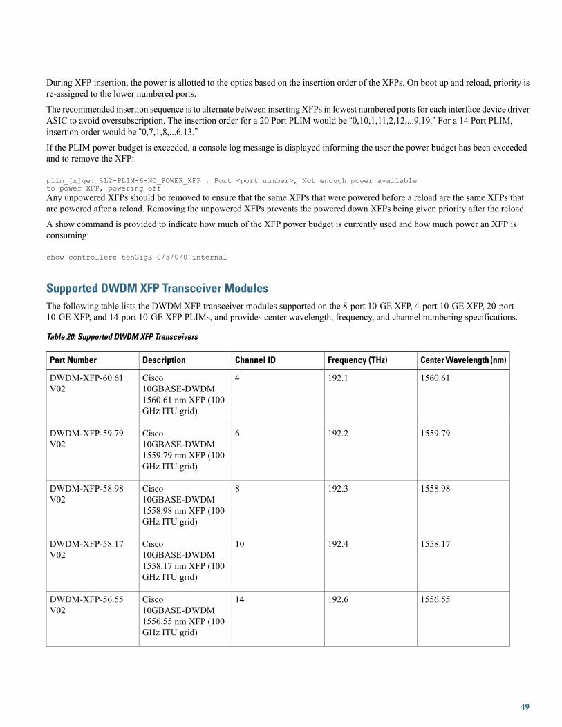
Supported DWDM XFP Transceiver ModulesThe following table lists the DWDM XFP transceiver modules supported on the 8-port 10-GE XFP, 4-port 10-GE XFP, 20-port10-GE XFP, and 14-port 10-GE XFP PLIMs, and provides center wavelength, frequency, and channel numbering specifications.
Table 20: Supported DWDM XFP Transceivers
Center Wavelength (nm)Frequency (THz)Channel IDDescriptionPart Number
1560.61192.14Cisco10GBASE-DWDM1560.61 nm XFP (100GHz ITU grid)
DWDM-XFP-60.61V02
1559.79192.26Cisco10GBASE-DWDM1559.79 nm XFP (100GHz ITU grid)
DWDM-XFP-59.79V02
1558.98192.38Cisco10GBASE-DWDM1558.98 nm XFP (100GHz ITU grid)
DWDM-XFP-58.98V02
1558.17192.410Cisco10GBASE-DWDM1558.17 nm XFP (100GHz ITU grid)
DWDM-XFP-58.17V02
1556.55192.614Cisco10GBASE-DWDM1556.55 nm XFP (100GHz ITU grid)
DWDM-XFP-56.55V02
49

Center Wavelength (nm)Frequency (THz)Channel IDDescriptionPart Number
1555.75192.716Cisco10GBASE-DWDM1555.75 nm XFP (100GHz ITU grid)
DWDM-XFP-55.75V02
1554.94192.818Cisco10GBASE-DWDM1554.94 nm XFP (100GHz ITU grid)
DWDM-XFP-54.94V02
1554.13192.920Cisco10GBASE-DWDM1554.13 nm XFP (100GHz ITU grid)
DWDM-XFP-54.13V02
1552.52193.124Cisco10GBASE-DWDM1552.52 nm XFP (100GHz ITU grid)
DWDM-XFP-52.52V02
1551.72193.226Cisco10GBASE-DWDM1551.72 nm XFP (100GHz ITU grid)
DWDM-XFP-51.72V02
1550.92193.328Cisco10GBASE-DWDM1550.92 nm XFP (100GHz ITU grid)
DWDM-XFP-50.92V02
1550.12193.430Cisco10GBASE-DWDM1550.12 nm XFP (100GHz ITU grid)
DWDM-XFP-50.12V02
1548.51193.634Cisco10GBASE-DWDM1548.51 nm XFP (100GHz ITU grid)
DWDM-XFP-48.51V02
1547.72193.736Cisco10GBASE-DWDM1547.72 nm XFP (100GHz ITU grid)
DWDM-XFP-47.72V02
1546.92193.838Cisco10GBASE-DWDM1546.92 nm XFP (100GHz ITU grid)
DWDM-XFP-46.92V02
50

Center Wavelength (nm)Frequency (THz)Channel IDDescriptionPart Number
1546.12193.940Cisco10GBASE-DWDM1546.12 nm XFP (100GHz ITU grid)
DWDM-XFP-46.12V02
1544.53194.144Cisco10GBASE-DWDM1544.53 nm XFP (100GHz ITU grid)
DWDM-XFP-44.53V02
1543.73194.246Cisco10GBASE-DWDM1543.73 nm XFP (100GHz ITU grid)
DWDM-XFP-43.73V02
1542.94194.348Cisco10GBASE-DWDM1542.94 nm XFP (100GHz ITU grid)
DWDM-XFP-42.94V02
1542.14194.450Cisco10GBASE-DWDM1542.14 nm XFP (100GHz ITU grid)
DWDM-XFP-42.14V02
1540.56194.854Cisco10GBASE-DWDM1540.56 nm XFP (100GHz ITU grid)
DWDM-XFP-40.56V02
1539.77194.756Cisco10GBASE-DWDM1539.77 nm XFP (100GHz ITU grid)
DWDM-XFP-39.77V02
1539.98194.858Cisco10GBASE-DWDM1539.98 nm XFP (100GHz ITU grid)
DWDM-XFP-38.98V02
1538.19194.960Cisco10GBASE-DWDM1538.19 nm XFP (100GHz ITU grid)
DWDM-XFP-38.19V02
1536.61195.164Cisco10GBASE-DWDM1536.61 nm XFP (100GHz ITU grid)
DWDM-XFP-36.61V02
51

Center Wavelength (nm)Frequency (THz)Channel IDDescriptionPart Number
1535.82195.266Cisco10GBASE-DWDM1535.82 nm XFP (100GHz ITU grid)
DWDM-XFP-35.82V02
1535.04195.368Cisco10GBASE-DWDM1535.04 nm XFP (100GHz ITU grid)
DWDM-XFP-35.04V02
1534.25195.470Cisco10GBASE-DWDM1534.25 nm XFP (100GHz ITU grid)
DWDM-XFP-34.25V02
1532.68195.674Cisco10GBASE-DWDM1532.68 nm XFP (100GHz ITU grid)
DWDM-XFP-32.68V02
1531.90195.776Cisco10GBASE-DWDM1531.90 nm XFP (100GHz ITU grid)
DWDM-XFP-31.90V02
1531.12195.878Cisco10GBASE-DWDM1531.12 nm XFP (100GHz ITU grid)
DWDM-XFP-31.12V02
1530.33195.580Cisco10GBASE-DWDM1530.33 nm XFP (100GHz ITU grid)
DWDM-XFP-30.33V02
SFP+ Module ConnectionsThe enhanced small form-factor pluggable (SFP+) module is an enhanced version of the SFP module, supporting data rates up to 10Gbps. The SFP+ module is a hot-swappable input/output (I/O) device that plugs into an Ethernet SFP+ port on the 40-Port 10-GEPLIM. It has optical interoperability with 10GBASE XENPAK, 10GBASE X2, and 10GBASE XFP interfaces on the same link.
The 40-Port 10-GE PLIM accepts only the SFP+ modules listed as supported in this document. An SFP+ module check is run everytime an SFP+ is inserted, and only SFP+ modules that pass this check can be used by the 40-port 10-GE PLIM.
SFP+ modules exist for technologies other than GE and for products other than the 40-Port 10-GE PLIM. However, the informationin this document pertains only to SFP+ modules that plug into the 40-Port 10-GE PLIM ports.
The SFP+ module has a receiver port (RX) and a transmitter port (TX) that compose one optical interface.
52

Table 21: 40-Port and GE SFP+ Module Options
DescriptionSFP ModuleSFP Module Product Number
Supports a link length of 26m on standardFiber Distributed Data Interface(FDDI)-grade multimode fiber (MMF).Using 2000MHz kmMMF (OM3), up to300m link lengths are possible. Using4700MHz 1 km MMF (OM4), up to400m link lengths are possible.
Except for version 1, whichsupports only 10GBASE-SR.
Note
SFP+ transceiver module for MMF,850-nm wavelength, LC duplexconnector
SFP-10G-SR
10GBASE-SR SFP+ transceiver module(Multirate optics)
SFP-10G-SR-X
Supports a link length of 10 kilometerson standard single-mode fiber (SMF,G.652).
SFP+ transceiver module for SMF,1310-nm wavelength, LC duplexconnector
SFP-10G-LR
10GBASE-LR SFP+ transceiver module(Multirate optics)
SFP-10G-LR-X
Supports link lengths of 220m onstandard Fiber Distributed Data Interface(FDDI)-grade multimode fiber (MMF).
To ensure that specifications aremet over FDDI-grade, OM1 andOM2 fibers, the transmittershould be coupled through amode conditioning patch cord.No mode conditioning patchcord is required for applicationsover OM3 or OM4.
Note
10GBASE-LRM SFP+ transceivermodule for MMF and SMF, 1310-nmwavelength, LC duplex connector
SFP-10G-LR-M
Supports a link length of up to 40kilometers on standard single-mode fiber(SMF, G.652).
SFP+ transceiver module for SMF,1550-nm, LC duplex connector
SFP-10G-ER
Supports link lengths of up to about 80kilometers on standard single-mode fiber(SMF, G.652). This interface is notspecified as part of the 10GE standardand is instead built according to Ciscospecifications.
SFP+ transceiver module for SMF,1550-nm, LC duplex connector
SFP-10G-ZR
53

Table 22: SFP+ Optical Transmit and Receive Specifications
Transmit and ReceiveWavelength (nm)
Receive Power (dBm)Transmit Power (dBm)1
TypeProductTransmitterand receiverpower is inaverage,unlessspecified.
NoteTransmitterand receiverpower is inaverage,unlessspecified.
Note
840 to 860Maximum: -1.0
Minimum: -9.9
Maximum: -1.2The launchpower shall bethe lesser of theclass 1 safetylimit or themaximumreceive power.Class 1 laserrequirementsare defined byIEC 60825-1:2001.
Note
Minimum: -7.3
10GBASE-SR 850nmMMF
SFP-10G-SR
SFP-10G-SR-X
1260 to 1355Maximum: 0.5
Minimum: -14.4
Maximum: 0.5
Minimum: -8.2
10GBASE-LR 1310nmSMF
SFP-10G-LR
SFP-10G-LR-X
1260 to 1355Maximum: 0.5
Minimum: -8.4 (inaverage and -6.4 inOMA)
Both averageand OMAspecificationsmust be metsimultaneously.
Note
Maximum: 0.5
Minimum: -6.5
10GBASE-LRM1310nmMMFandSMF
SFP-10G-LR-M
1530 to 1565Maximum: -1
Minimum: -15.8
Maximum: 4.0
Minimum: -4.7
10GBASE-ER 1550nmSMF
SFP-10G-ER
Transmitter: 1530 to1565
Receiver: 1260 to 1565
-Optical output powermaximum: 0
Optical output powerminimum: 4.0
10GBASE-ZR 1550nmSMF
SFP-10G-ZR
54
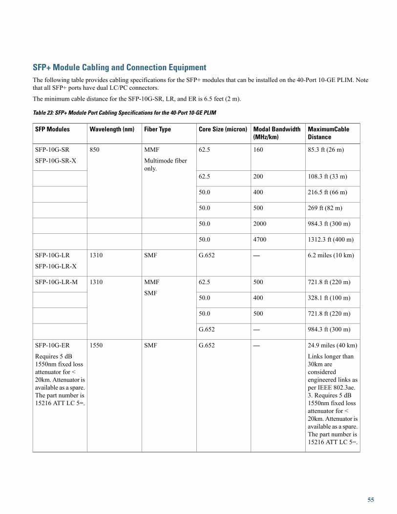
SFP+ Module Cabling and Connection EquipmentThe following table provides cabling specifications for the SFP+ modules that can be installed on the 40-Port 10-GE PLIM. Notethat all SFP+ ports have dual LC/PC connectors.
The minimum cable distance for the SFP-10G-SR, LR, and ER is 6.5 feet (2 m).
Table 23: SFP+ Module Port Cabling Specifications for the 40-Port 10-GE PLIM
MaximumCableDistance
Modal Bandwidth(MHz/km)
Core Size (micron)Fiber TypeWavelength (nm)SFP Modules
85.3 ft (26 m)16062.5MMF
Multimode fiberonly.
850SFP-10G-SR
SFP-10G-SR-X
108.3 ft (33 m)20062.5
216.5 ft (66 m)40050.0
269 ft (82 m)50050.0
984.3 ft (300 m)200050.0
1312.3 ft (400 m)470050.0
6.2 miles (10 km)—G.652SMF1310SFP-10G-LR
SFP-10G-LR-X
721.8 ft (220 m)50062.5MMF
SMF
1310SFP-10G-LR-M
328.1 ft (100 m)40050.0
721.8 ft (220 m)50050.0
984.3 ft (300 m)—G.652
24.9 miles (40 km)
Links longer than30km areconsideredengineered links asper IEEE 802.3ae.3. Requires 5 dB1550nm fixed lossattenuator for <20km. Attenuator isavailable as a spare.The part number is15216 ATT LC 5=.
—G.652SMF1550SFP-10G-ER
Requires 5 dB1550nm fixed lossattenuator for <20km. Attenuator isavailable as a spare.The part number is15216 ATT LC 5=.
55

Table 24: SFP+ Optical Modules Color Codes
Bail Latch ColorProduct
BeigeCisco SFP-10G-SR
BlueCisco SFP-10G-LR
RedCisco SFP-10G-ER
GreenCisco SFP-10G-ZR
Cabling and Specifications for 10-GE PLIMsThe following sections provide information about specifications and cabling for 10-GE Ethernet PLIMs:
Specifications for 10-GE XENPAK Interfaces
The 10-GE XENPAK optics modules use single-mode fiber-optics with SC connectors. The maximum distance for single-modeinstallations is determined by the amount of light loss in the fiber path. If your environment requires the light to travel close to thetypical maximum distance (as listed in the following table), you should use an optical time domain reflectometer (OTDR) to measurethe power loss.
Two types of 10-GE XENPAK interfaces are available: long wavelength, 1310 nanometers (nm), and extra-long wavelength, 1550nm.
The following table lists the specifications for the 10-GE XENPAK interfaces. The actual distance in any given case depends on thequality of the fiber connected to the transceiver.
56

Table 25: 10-GE XENPAK Optics Specifications
ExtraLongWavelength
LongWavelength
Specification
6.2miles(10km)
Targetdistance
57

ExtraLongWavelength
LongWavelength
Specification
24.8miles(40km)
Requiresa 5
Note
dB,1550nmfixedlossattenuatorfordistanceslessthan20km.Linkslonger than
Note
30 km areconsideredengineeredlinksmeaningthat, fordistancesup to 30km, nospecial linkdesignrules needto beconsidered.Linkdistancesbeyond 30km requirethat youverify thecablecharacteristics;inparticular,you shouldverify thecable's loss
58

ExtraLongWavelength
LongWavelength
Specification
value.
1530-1565nm
1260-1355nm
OperatingWavelengthRange
Transmitter
–4.7to+4.0dBm
–8.2to+0.5dBm
Transmitopticalpowerrange
Receiver
–15.8to–1.0dBm
–14.4to+0.5dBm
Receiveopticalpowerrange
Optical Link
G.652(SMF)
G.652(single-modefiber[SMF])
Fibertype
15dB
9.4dB
Opticalpowerbudget
IEEE802.3ae10GBASE-ER
IEEE802.3ae10GBASE-LR
Compliance
The abbreviation dBm (decibel) indicates dB referenced to 1.0 milliwatt. One milliwatt is zero dBm.Tip
Specifications for 10-GE DWDM XENPAK Interfaces
The 10-GE DWDM XENPAK optics modules use single-mode fiber-optics with SC connectors. When the input power is more thanthe maximum receive power, you need an attenuator installed in the RX port to bring the optical power to the receiver to the correctrange.
The 10-GE DWDM XENPAK interfaces are long-wavelength, 1310 nanometers (nm).
59

The following table lists the specifications of the 10-GE DWDM XENPAK interfaces.
Table 26: 10-GE DWDM XENPAK Optics Specifications
ValueSpecification
Transmitter
0.2 nmSpectralwidth
Fullwidth,–20 dBfrommaximum,withresolutionbandwidth(RBW)= 0.01nm
Note
–1 to +3dBm
Transmitopticalpowerrange
30 dBSide-modesuppressionratio(SMSR)
9 dBTransmitterextinctionratio(OMI)
Receiver
1530 to1565 nm
Receiveropticalinputwavelength
–1 dBmReceiverdamagethreshold
–500 to1600ps/nm
Dispersiontolerance
60

ValueSpecification
–24 to –7dBm
Receiveopticalpowerrange
Measuredat opticalsignal-to-noiseratio(OSNR) of30 dB at0.1 nmRBW.
Note
Input optical power to the XENPAK module must be less than –1 dBm to avoid damaging the receiver.Caution
Never connect a fiber loopback to the TX and RX ports without an attenuator. Use a 15 dB attenuator fordirect fiber loopbacks.
Caution
Specifications for 10-GE DWDM Tunable Interfaces
Each 10-GE DWDM line interface provides one 10-Gbps, long-reach, ITU-compliant, 50-GHz-spaced optical interface using LCconnectors supporting 10-GE LAN PHY interfaces. The output line interface is tunable across 82 adjacent 50-GHz wavelengths,enabling support for C-Band DWDM networks. The following table lists the optics specifications of the interfaces on the 10-GEWDMPHY PLIM.
Table 27: 10-GE WDMPHY PLIM Optics Specifications
ValueSpecification
C-BandUnit:Fullytunablefrom1529.55to1561.84
Nominalwavelengths(lambdaTnom)
1530 to1561 nm
Spectralrange(lambdaTmintolambdaTmax)
61

ValueSpecification
25 GHzSpectralwidth at20dB(lambdadelta20)
Optical Transmitter
Lithiumniobateexternalmodulator
Type
+3 dBm,+6 dBm
Outputpower(PTmintoPTmax)
27 dBRequiredopticalreturnloss,minimum(ORLmin)
>10.5 dBExtinctionratio,minimum(reminx)
Optical Receiver
Avalanchephotodiode(APD)
Type
Up to±1200ps/nm (2dBpenalty)
Chromaticdispersiontolerance(DLRmax)
62

ValueSpecification
–27 dBReflectancebetweenfar-endTX andnear-endRX(maximum)
–14 dBReceiverreflectance(maximum)
1290 nmto 1605nm
Inputwavelengthbandwidth(lambdac_rx)
The following table indicates the optical performance of the 10-GE WDMPHY PLIM.
Table 28: Optical Performance of 10-GE WDMPHY PLIM
CD ToleranceInput PowerSensitivity
Post-FEC BERPre-FEC BERFEC TypeOSNROSNRRBW is 0.5nm
Note
±1200 ps/nm–8 to –20 dBmC-Band
—Less than 10E–12OFF23 dB
±1000 ps/nm–8 to –20 dBmC-Band
—Less than 10E–12OFF19 dB
—–8 to –22 dBmC-Band
—Less than 10E–12OFF19 dB
±800 ps/nm–8 to –18 dBmLess than 10E–15Less than 10E–5GFEC10 dB
—–8 to –18 dBmLess than 10E–15Less than 10E–5GFEC8.5 dB
±800 ps/nm–8 to –26 dBmLess than 10E–15Less than 7 x10E–4
EFEC19 dB
—–8 to –27 dBmLess than 10E–15Less than 7 x10E–4
EFEC19 dB
±800 ps/nm–8 to –18 dBmLess than 10E–15Less than 7 x10E–4
EFEC7 dB
63

CD ToleranceInput PowerSensitivity
Post-FEC BERPre-FEC BERFEC TypeOSNROSNRRBW is 0.5nm
Note
—–8 to –18 dBmLess than 10E–15Less than 7 x10E–4
EFEC5 dB
Input optical power to the 10-GE WDMPHY PLIM must be less than 0 dBm to avoid damaging thereceiver.
Caution
Cabling a 10-GE XFP Transceiver
Use this procedure to cable 10-GE XFP transceivers:
Before removing the dust plugs and making any optical connections, follow these guidelines:
• Always keep the protective dust plugs on the unplugged fiber-optic cable connectors and the transceiver optical bores until youare ready to make a connection.
• Always inspect and clean the LC connector end faces just before making any connections. For more information on cleaningfiber-optic connections, see the How to Remove or Install a PLIM Cable Management Bracket, on page 101 section.
• Always grasp the LC connector housing to plug or unplug a fiber-optic cable.
Procedure
Step 1 Remove the dust plugs from the optical network interface cable LC connectors (see Figure 36: Installing the 10-GE XFPTransceiver Module). Save the dust plugs for future use.
Step 2 Inspect and clean the LC connector’s fiber-optic end faces.Step 3 Remove the dust plugs from the XFP transceiver module optical bores.Step 4 Immediately attach the network interface cable LC connectors to the XFP transceiver module. (See the following figure
for an illustration of cabling the XFP transceiver module.)
Figure 27: Cabling a10-GE XFP Transceiver Module
64

About Fiber-Optic Interface Cables
The Ethernet PLIMs use single-mode fiber-optic interface cables to connect to another Ethernet interface, router, or switch. The10-GE PLIM with 10-GE XENPAK modules and 10-GE DWDM XENPAK modules use cables with SC connectors; the 10-GEWDMPHY PLIM uses cables with LC connectors.
Fiber-optic cables are not available from Cisco Systems. They can be purchased from cable vendors.Note
Single-mode cables are generally yellow in color. You can use two cables with simplex connectors or one cable with dual, keyedconnectors.
Because invisible radiation may be emitted from the aperture of the port when no fiber cable is connected,avoid exposure to radiation and do not stare into open apertures. Statement 125
Warning
Figure 28: Simplex SC Cable Connector (Single Mode)
Spring-action disconnect latch2SC cable connector1
65
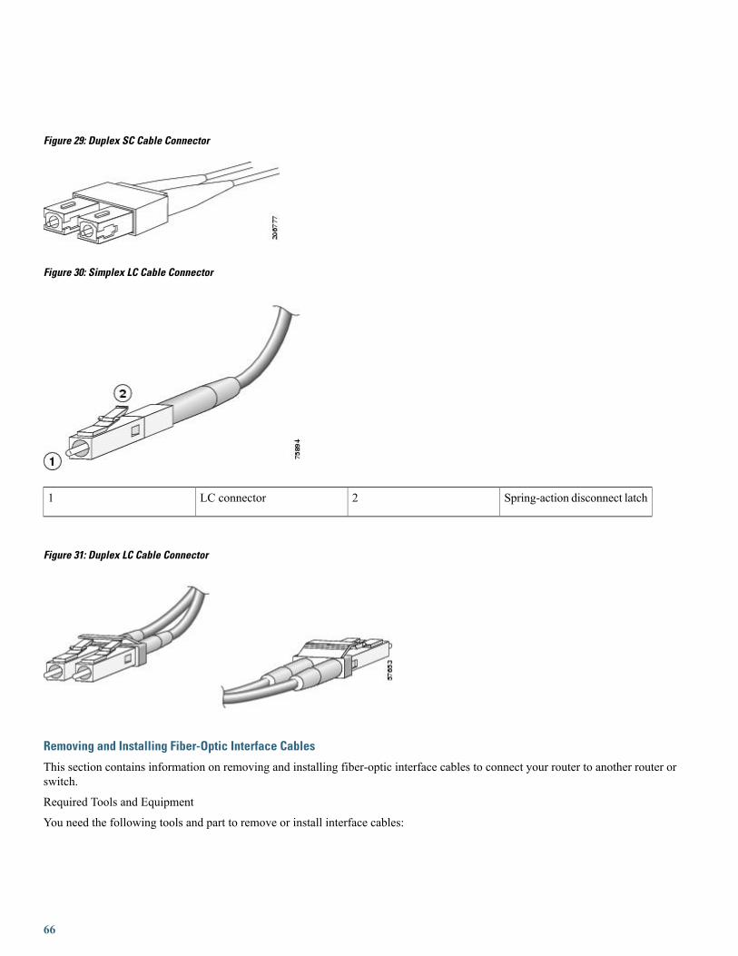
Figure 29: Duplex SC Cable Connector
Figure 30: Simplex LC Cable Connector
Spring-action disconnect latch2LC connector1
Figure 31: Duplex LC Cable Connector
Removing and Installing Fiber-Optic Interface Cables
This section contains information on removing and installing fiber-optic interface cables to connect your router to another router orswitch.
Required Tools and Equipment
You need the following tools and part to remove or install interface cables:
66

• ESD-preventive wrist strap
• Medium (Number 2) Phillips screwdriver
• Interface cables
Removing Fiber-Optic Interface Cables
To remove interface cables, see the following figure and follow these steps:
Procedure
Step 1 Attach an ESD-preventive wrist or ankle strap to your wrist and follow its instructions for use.Step 2 Press on the spring-action disconnect latch to disconnect the interface cable connectors from the PLIM interface ports.
When the cable is removed from the 10-GE PLIM, the spring-loaded cover plate folds over to cover the interface port.Note that the other PLIMs do not have spring-loaded cover plates that cover their interface ports.
Because invisible radiation may be emitted from the aperture of the port when no fiber cable is connected,avoid exposure to radiation and do not stare into open apertures. Statement 125
Warning
67

You do not have to remove the interface cables from the PLIM cable management bracket. If you are replacing the PLIM,you can remove the cable management bracket from the PLIM. After you install a new PLIM, you can attach the cablemanagement bracket to the new PLIM and reattach the interface cables. See the How to Remove or Install a PLIM CableManagement Bracket, on page 101.
Figure 32: Interface Cables Installation and Removal (10-GE PLIM Shown)
Cable management bracket3Fiber cable1
Note
Dust plug4Velcro strap2
Installing Fiber-Optic Interface CablesUse two simplex connectors or one duplex connector (see the previous figures).
68
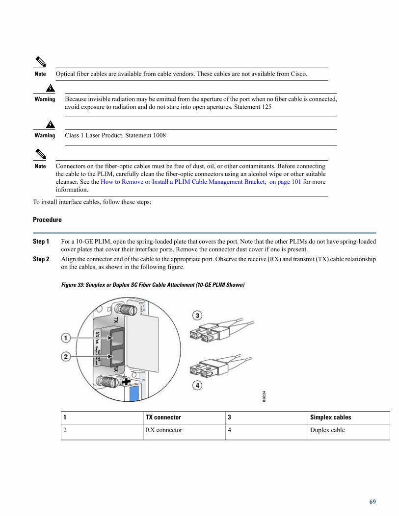
Optical fiber cables are available from cable vendors. These cables are not available from Cisco.Note
Because invisible radiation may be emitted from the aperture of the port when no fiber cable is connected,avoid exposure to radiation and do not stare into open apertures. Statement 125
Warning
Class 1 Laser Product. Statement 1008Warning
Connectors on the fiber-optic cables must be free of dust, oil, or other contaminants. Before connectingthe cable to the PLIM, carefully clean the fiber-optic connectors using an alcohol wipe or other suitablecleanser. See the How to Remove or Install a PLIM Cable Management Bracket, on page 101 for moreinformation.
Note
To install interface cables, follow these steps:
Procedure
Step 1 For a 10-GE PLIM, open the spring-loaded plate that covers the port. Note that the other PLIMs do not have spring-loadedcover plates that cover their interface ports. Remove the connector dust cover if one is present.
Step 2 Align the connector end of the cable to the appropriate port. Observe the receive (RX) and transmit (TX) cable relationshipon the cables, as shown in the following figure.
Figure 33: Simplex or Duplex SC Fiber Cable Attachment (10-GE PLIM Shown)
Simplex cables3TX connector1
Duplex cable4RX connector2
69

Step 3 Attach a fiber cable between the port in the PLIM and the device to which the PLIM is connected.Step 4 Insert the fiber cable connector until it clicks and locks into place.Step 5 Repeat these steps until all cabling is completed.
The fiber-optic connectors must be free of dust, oil, or other contaminants. Carefully clean the fiber- opticconnectors using an alcohol wipe or other suitable cleanser.
Note
Cleaning Fiber-Optic Connectors
It is important to inspect and clean fiber-optic components before making a fiber-optic connection (for example, plugging a fiber-opticconnector into a fiber-optic receptacle). Any contamination in the fiber connection can cause the optic component or the whole systemto fail. Even microscopic dust particles, oil from human hands, film residues (condensed from vapors in the air), and powdery coatings(left after water or other solvents evaporate) can cause a variety of problems for optical connections.
With the high-powered lasers now in use, any contaminant can be burned into the fiber end face if it blocksthe core while the laser is turned on. This burning may damage the optical surface enough that it cannotbe cleaned.
Caution
For instructions on how to clean fiber-optic components, see:
http://www.cisco.com/warp/public/127/cleanfiber2.html
Always follow the fiber-optic cleaning procedures carefully. The goal is to eliminate any dust or contamination and provide a cleanenvironment for the fiber-optic connection. Inspection, cleaning, and reinspection are critical steps that must be performed beforemaking any fiber-optic connection.
How to Remove or Install a XENPAK Optics ModuleThe 10-GE XENPAK PLIMs support the DWDM XENPAK optics modules listed in Table 2: PLIM Descriptions and Software andHardware Compatibility. These optics modules are installed in ports on the PLIM and provide the optical interface connectors forthe PLIM.
XENPAK optics modules are keyed so that they cannot be inserted incorrectly. The PLIM automaticallyshuts down any optics module that is not a valid type.
Note
70

The following figure shows a DWDM XENPAK optics module.
Figure 34: DWDM XENPAK Optics module
Transmit (TX) optical bore4Captive installation screws1
Receive (RX) optical bore5Center wavelength warninglabel
2
XENPAK module label6Dust plug3
This section contains the following procedures:
Prerequisites
To stay within the maximum received power specification on the RX side of the XENPAK module, an attenuator might be required.To determine if an attenuator is needed for the XENPAK module, see Specifications for 10-GE XENPAK Interfaces, on page 56section.
Required Tools and Equipment
Have the following equipment available before you install or remove a XENPAK module:
• Dust plugs to keep unused ports clean
• Antistatic surface on which to place the module
• Attenuator, if one is determined to be needed in the prerequisites
Removing a XENPAK Optics Module
This section describes how to remove a XENPAK optics module from the PLIM.
71

Procedure
Step 1 Use the shutdown command before you remove a XENPAK optics module.It is important to use the shutdown command to prevent anomalies from occurring when you install a newXENPAK module.
Caution
Step 2 Disconnect any network interface cables that are attached to the optics module, and install the optical bore dust plugs.Step 3 Loosen the two captive screws securing the optics module in the PLIM.Step 4 Carefully pull the two captive screws to disconnect the optics module from the connector within the PLIM port.Step 5 Grasp the edges of the optics module, and carefully slide it from the PLIM port.Step 6 Place the optics module on an antistatic surface.
Installing a XENPAK Optics Module
This section describes how to install a XENPAK optics module in the PLIM.
Procedure
Step 1 Remove the optics module from its protective packaging.Step 2 Align the optics module with the PLIM port, and slide the module into the port until the back of the optics module faceplate
is flush with the PLIM faceplate. This step ensures proper connection between the PLIM connector and the optics moduleconnector. XENPAK modules are keyed so that they cannot be inserted incorrectly.
Step 3 Secure the optics module by tightening the two captive installation screws. Do not cross-thread or overtighten the captivescrews.
Make sure that the optics module is fully inserted into the PLIM port and that the captive screws are fully tightenedbefore attaching the fiber-optic interface cable to the optics module connector.
Note
Step 4 Remove the optical bore dust plugs from the optics module, and attach the network interface cable to the optics moduleconnector.
How to Remove or Install an XFP ModuleThe 10-GEXFP PLIMs support the XFP opticsmodules listed in Table 2: PLIMDescriptions and Software andHardware Compatibility.The 10-GE XFP transceiver module is a hot-swappable I/O device that plugs into 10-GE ports (see the following figure). The XFPtransceiver module connects the electrical circuitry of the system with the optical network.
The dual LC connector on the XFP transceiver modules supports network interface cables with eitherPhysical Contact (PC) or Ultra-Physical Contact (UPC) polished face types. The dual LC connector onthe XFP transceiver modules does not support network interface cables with an Angle Polished Connector(APC) polished face type.
Note
72
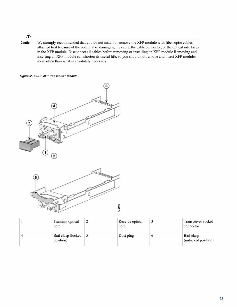
We strongly recommended that you do not install or remove the XFP module with fiber-optic cablesattached to it because of the potential of damaging the cable, the cable connector, or the optical interfacesin the XFP module. Disconnect all cables before removing or installing an XFP module.Removing andinserting an XFP module can shorten its useful life, so you should not remove and insert XFP modulesmore often than what is absolutely necessary.
Caution
Figure 35: 10-GE XFP Transceiver Module
Transceiver socketconnector
3Receive opticalbore
2Transmit opticalbore
1
Bail clasp(unlocked position)
6Dust plug5Bail clasp (lockedposition)
4
73

Installing a 10-GE XFP Transceiver Module
The XFP transceiver is a static-sensitive device. Always use an ESD wrist strap or similar individualgrounding device when handling XFP transceivers or coming into contact with system modules.
Caution
To install an XFP transceiver, follow these steps:
Procedure
Step 1 Remove the XFP transceiver from its protective packaging.Step 2 Check the label on the XFP transceiver body to verify that you have the correct model for your network.Step 3 Position the XFP transceiver in front of the XFP socket opening on the module. Slide the XFP transceiver part of the way
into the transceiver socket on the system module front panel.Step 4 Remove the optical bore dust plug from the XFP transceiver.Step 5 Pivot the bail clasp up so that it is parallel with the transceiver body (see the following figure).Step 6 Continue sliding the XFP transceiver into the socket until the XFP transceiver is mated with the transceiver socket connector.Step 7 Latch the XFP transceiver in the transceiver socket by pivoting the bail clasp down so that the bail clasp is perpendicular
to the transceiver body (see the following figure).
74

If the latch is not fully engaged, you may accidentally disconnect the XFP transceiver.Caution
Figure 36: Installing the 10-GE XFP Transceiver Module
Step 8 Immediately reinstall the dust plug in the XFP transceiver optical bores. Do not remove the dust plug until you are readyto attach the network interface cable.
10-Gigabit XFP transceivers are keyed to prevent incorrect insertion.Note
Removing a 10-GE XFP Transceiver Module
The XFP transceiver is a static-sensitive device. Always use an ESD wrist strap or similar individualgrounding device when handling XFP transceivers or coming into contact with modules.
Caution
If you are removing an XFP transceiver, follow these steps:
75

Procedure
Step 1 Disconnect the network interface cable from the XFP transceiver connectors.Step 2 Pivot the XFP transceiver bail clasp up to release the XFP transceiver from the socket (see the following figure).Step 3 Slide the XFP transceiver out of the socket. Pivot the bail clasp down and immediately install the dust plug in the XFP
transceiver optical bores (see the following figure).Step 4 Immediately place the XFP transceiver in an antistatic bag.
Figure 37: Removing a 10-GE XFP Transceiver
40-GE PLIMsThis section provides information specific to the following 40-GE PLIMs:
76

The CFP Transceiver Module supported for the 2-port and 4-port PLIMs is described in the following section: 40-GE Ethernet CFPTransceiver Module, on page 80.
2-Port 40-GE OTU3 PLIM with CFP Optics ModuleThe 2-port 40-GE OTU3 PLIM supports up to 2 40-GE C Form-factor Pluggable (CFP) optics modules.
Supported CFP Optical Transceiver Modules
• CFP-40G-LR4
• CFP-40G-FR
• CFP-40G-SR4
SR4 optics do not support OTN.Note
Cisco qualifies the optics that are approved for use with its PLIMs.
For more details, see Changes to This Document, on page 2.
Ports and LEDs
The 2-port 40-GE OTU3 CFP PLIM has:
• Two ports that accept CFP optics modules
• Status LED for the PLIM
• One LED indicator for each port
The following figure shows the front panel of the 2-port 40-GE OTU3 CFP PLIMs.
Figure 38: 2-port 40-GE OTU3 CFP PLIM front panel
Status LED2Port LED (one per port)1
The following table describes the PLIM LEDs for the 2-port 40-GE OTU3 CFP PLIM.
77

Table 29: 2-port 40-GE OTU3 CFP PLIM LED Descriptions
DescriptionStateLED
PLIM is powered on and operatingcorrectly.
GreenStatus
PLIM is powered on but is initializing.Yellow
PLIM is powered off or power on did notcomplete successfully.
Off
Port is enabled by software and there isa valid link.
GreenPort
The port is enabled by software, but thereis a problem with the link.
Yellow
Port is not enabled by software or thePLIM is powered off.
Off
Physical Characteristics
• Height—20.6 in (52.2 cm)
• Depth—11.2 in (28.4 cm)
•Width—1.8 in (4.49 cm)
•Weight—9.45 lb (4.27 kg)
• Power consumption—160 W
40-GE Ethernet CFP Transceiver ModuleThe 4-port 40-GE OTU3 PLIM supports up to 4 40-GE C Form-factor Pluggable (CFP) optics modules. The 4-port 40-GE OTU3CFP PLIM is a high-powered PLIM.
Power Management Restrictions
The following restrictions apply only to the legacy 16-slot chassis.Note
Cisco CRS high-powered PLIMs are subject to slot placement restrictions on the legacy 16-slot chassis. The following error messageappears if these restrictions are not followed:
PLATFORM-SHELFMGRV2-4-HIGH_POWERED_PLIM_NOT_POWERED_ON_IN_LOWER_BAY
The following PLIMs are high-powered PLIMs:
• CRS-CGSE-PLIM—Cisco CRS Carrier Grade Services Engine (CGSE) PLIM
78

• 1OC768-DPSK/C-O—Cisco CRS-1 1xOC768 (C-band) DPSK+ DWDM PLIM (Offset TDC)
• 6-10GE-WLO-FLEX—Cisco CRS Flexible PLIM
• 4-40GE-L/OTN—Cisco CRS 4-Port 40 GE LAN/OTN Interface Module
The rules for placement of high-powered PLIMs are:
1 A FLEX PLIM (6-10GE-WLO-FLEX) in the lower shelf cannot be placed under a CGSE PLIM directly above in the upper shelf.2 High-powered PLIMs may only be placed in lower slots if a high-powered PLIM is in the slot directly above or if the slot above
is empty.
Supported CFP Optical Transceiver Modules
• CFP-40G-LR4
• CFP-40G-FR
• CFP-40G-SR4
SR4 optics do not support OTN.Note
Cisco qualifies the optics that are approved for use with its PLIMs.
For more details, see Changes to This Document, on page 2.
Ports and LEDs
The 4-port 40-GE OTU3 CFP PLIM has:
• Four ports that accept CFP optics modules
• Status LED for the PLIM
• One LED indicator for each port
The following figure shows the front panel of the 4-port 40-GE OTU3 CFP PLIMs.
Figure 39: 4-port 40-GE OTU3 CFP PLIM front panel
Status LED2Port LED (one per port)1
The following table describes the PLIM LEDs for the 4-port 40-GE OTU3 CFP PLIM.
79

Table 30: 4-port 40-GE OTU3 CFP PLIM LED Descriptions
DescriptionStateLED
PLIM is powered on and operatingcorrectly.
GreenStatus
PLIM is powered on but is initializing.Yellow
PLIM is powered off or power on did notcomplete successfully.
Off
Port is enabled by software and there isa valid link.
GreenPort
The port is enabled by software, but thereis a problem with the link.
Yellow
Port is not enabled by software or thePLIM is powered off.
Off
Physical Characteristics
• Height—20.6 in (52.2 cm)
• Depth—11.2 in (28.4 cm)
•Width—1.8 in (4.49 cm)
•Weight—11.769 lb (5.34 kg)
• Power consumption—185 W
Oversubscription of 40-GE Ports
Processing on the 4-port 40-GE OTU3 CFP PLIM is performed by two PLIM hardware controllers, each of which can process up to80 Gbps of traffic. Ports 0 and 1 are associated with one PLIM hardware controller, while ports 2 and 3 are associated with the secondPLIM hardware controller. In addition, the PLIM ports are serviced by line card hardware controllers that have a total switchingcapacity of 140 Gbps.
Because of this PLIM design, maximum throughput on the 4-port 40-GE OTU3 CFP PLIM is limited to 140 Gbps evenly distributedacross the four ports. A second limitation exists, this time at the individual PLIM hardware controller level. For certain packet sizes,the effective bandwidth of the PLIM hardware controller can drop to as low as 73 Gbps (maximum 80 Gbps), which is distributedevenly to it's 2 connected ports (36.5 Gbps per port). Effective bandwidth of the PLIM hardware controller usually drops below80Gbps at smaller packet sizes (traffic streams that contain a relatively high proportion of packets sized below 128 bytes).
40-GE Ethernet CFP Transceiver ModuleThe 40-GE CFP transceiver module is a hot-swappable I/O device that plugs into 40-GE ports. The CFP transceiver module connectsthe electrical circuitry of the system with the optical network.
80

If no CFP optics module is to be installed in a port, the open port must be covered with a CFP-COVER(shipped with the card). The CFP-COVER is required under this condition to preserve the integrity of thecard and is required for EMC and Safety compliance and proper cooling in the chassis.
Caution
Review the safety information and guidelines before installing or removing a CFP transceiver module.See How to Remove or Install a PLIM , on page 97.
Note
Figure 40: CFP Transceiver Module
The CFP may also be a flat top. See Figure 42: CFP Transceiver Module.Note
Table 33: CFP Module Port Cabling Specifications provides cabling specifications for the CFP modules that can be installed on the2- or 4-port 40-GE OTU3 CFP PLIM.
Table 31: CFP Module Port Cabling Specifications
Typical MaximumDistance
Connector TypeFiber TypeWavelength (nm)Part Number
10 kmSCSMF1271129113111331CFP-40G-LR4
2 kmSCSMF1547.5CFP-40G-FR
81

Typical MaximumDistance
Connector TypeFiber TypeWavelength (nm)Part Number
100 mMPO (MultipathOptical)
MMF850CFP-40G-SR4
100-GE PLIMsThis section provides information specific to the following 100-GE PLIMs:
1-Port 100-GE PLIM with CFP Optics Module
The 1-port 100-GE CFP PLIM supports a single 100-GE C Form-factor Pluggable (CFP) optics module.
Supported CFP Optical Transceiver Modules
• CFP-100GE-LR4, V01
• CFP-100G-SR10
Cisco qualifies the optics that are approved for use with its PLIMs.
For the modules listed, use a single-mode optical fiber that has a modal-field diameter of 8.7 ±0.5 microns (nominal diameter isapproximately 10/125 micron) to connect your router to a network.
For more details, see 100-GE Ethernet CFP Transceiver Module, on page 84.
Ports and LEDs
The 1-port 100-GE CFP PLIM has:
• One port that accepts a CFP optics module
• Status LED for the PLIM
• Four LED indicators for the single port
The following figure shows the front panel of the 1-Port 100-GE CFP PLIMs.
Figure 41: 1-Port 100-GE CFP PLIM front panel
82

StatusLED
5Rx PKTLED
4Tx PKTLED
3Link LED2ActiveLED
1
The following table describes the PLIM LEDs for the 1-Port 100-GE CFP PLIM.
Table 32: 1-Port 100-GE CFP PLIM LED Descriptions
DescriptionStateLED
PLIM is properly seated and operatingcorrectly.
GreenPLIM Status
PLIM is powered on, but initializing.Yellow
PLIM is not properly seated, systempower is off, or power up did notcomplete successfully.
Off
Port is enabled by software and there isa valid link.
GreenActive
Port is enabled by software, but there isa problem with the link.
Yellow
Port is not enabled by software.Off
Valid link is achieved.GreenLink
Valid link is not achieved.Off
Packets are being transmitted on the port.Green (flashing)Tx PKT
No packets are being transmitted on theport.
Off
Packets are being received on the port.Green (flashing)Rx PKT
No packets are being received on the port.Off
Physical Characteristics
• Height—20.6 in (52.2 cm)
• Depth—11.2 in (28.4 cm)
•Width—1.8 in (4.49 cm)
•Weight—7.17 lbs (3.24 kg)
83

• Power consumption—150 W
100-GE Ethernet CFP Transceiver Module
The 100-GE CFP transceiver module is a hot-swappable I/O device that plugs into 100-GE ports (see the following figure). The CFPtransceiver module connects the electrical circuitry of the system with the optical network.
Figure 42: CFP Transceiver Module
The CFP uses duplex single mode SC fiber cabling. The following table provides cabling specifications for the CFP modules thatcan be installed on the 1-Port 100-GE CFP PLIM.
A CFP optics module must be installed in the CFP transceiver module slot of each 100GE PLIM installedin the Cisco CRS chassis. The CFP transceiver module preserves the integrity of the card and is requiredfor EMI and Safety compliance and proper cooling in the chassis.
Caution
Review the safety information and guidelines before installing or removing a CFP transceiver module.See How to Remove or Install a PLIM , on page 97.
Note
Table 33: CFP Module Port Cabling Specifications
Typical MaximumDistance
Fiber TypeWavelength (nm)DescriptionPart Number
6.213 miles
(10 km)
SMF1295.561300.0551304.5851309.14100-GE pluggableoptical transceivermodules
CFP-100GE-LR4, V01
100 mMMF1295.561300.0551304.5851309.14100 GE over 10short-reach optical lanes(SR10) optics(multimode fiber)
CFP-100G-SR10
84

1-Port 100-GE PLIM with IP over DWDM
The 1-port 100-GE DWDM PLIM supports the IP over DWDM optics module. The 1-port 100-GE IP over DWDM PLIM is athermally-sensitive PLIM. When used at high altitudes, it should be placed in the lower card cage.
Thermal Restrictions
The following restrictions apply only to the legacy 16-slot chassis.Note
Cisco CRS thermally-sensitive PLIMs are subject to slot placement restrictions on the legacy 16-slot chassis. The following errormessage appears if these restrictions are not followed:
PLATFORM-SHELFMGRV2-4-AVOID_THERMALLY_SENSITIVE_PLIM_IN_UPPER_SLOT
The thermally-sensitive PLIM limitation is due to the possibility of some components exceeding their rated temperature tolerancewhen the system is run at 50C at elevations of 1800 meters or higher. If the high temperature condition occurs, the environmentalmonitoring software will shut down the thermally-sensitive PLIM when its temperature reaches configured thresholds. Therefore,this restriction applies only to routers operating at these high elevations and may be ignored otherwise.
Ports and LEDs
The 1-port 100-GE IP over DWDM PLIM has:
• One port that accepts a DWDM optics module that is not pluggable
• Status LED for the PLIM
• One LED indicator for the single port
Cisco qualifies the optics that are approved for use with its PLIMs.
The following figure shows the front panel of the 1-port 100-GE IP over DWDM PLIMs.
Figure 43: 1-Port 100-GE DWDM PLIM front panel
Status LED2Port LED1
85

Table 34: 1-Port 100-GE CFP PLIM LED Descriptions
DescriptionStateLED
PLIM is powered on and operatingcorrectly.
GreenStatus
PLIM is powered on but is initializing.Yellow
PLIM is powered off or power up did notcomplete successfully.
Off
Port is enabled by software and there isa valid link.
GreenPort
Port is enabled by software, but there isa problem with the link.
Yellow
Port is not enabled by software.Off
Physical Characteristics
• Height—20.6 in (52.2 cm)
• Depth—11.2 in (28.4 cm)
•Width—1.8 in (4.49 cm)
•Weight—8.325 lb (3.78 kg)
• Power consumption—195 W
4-Port 100-GE PLIM with CPAK Optics Module
In the enhanced chassis, all 4 ports of this PLIM can be used. In the legacy chassis, this PLIM is operatedin 200G mode as a 2-port 100-GE CPAK PLIM. In this case, only the lower 2 ports are enabled.
Note
The 4-port 100-GE CPAK PLIM supports the CPAK optics module.
Ports and LEDs
The 4-port 100-GE CPAK PLIM has:
• Four ports that accept CPAK optics modules
• Status LED for the PLIM
• One LED indicator for the single port
86

Cisco qualifies the optics that are approved for use with its PLIMs.
The following figure shows the front panel of the 4-port 100-GE CPAK PLIMs.
Figure 44: 4-Port 100-GE CPAK PLIM front panel
Status LED2Port LED1
The 4-Port 100-GE PLIM comprises two sets of two ports, each of which are connected to a dedicated Network Processor. Whenoperated in the legacy chassis, the PLIM operates in 200G mode, in which the top set of ports and their Network Processor aredeactivated due to thermal constraints. In 200G mode, the port numbering will be different than 400G mode and will start with 0 forthe port that is labeled 2 in 400G mode. The faceplate labels therefore include two port numbers for the ports that are active in 200GMode, as shown in the following figure.
Figure 45: Half of the Front Panel, Showing Two Sets of Port Numbers
In the enhanced chassis, the 4-Port 10-GE PLIM may optionally operate in Green mode, in which two of the ports are deactivated(using the CLI) to save power. In Green mode, the port numbering follows the 400G mode model, which results in only ports 1-2being active. Ports 0-1 will not be visible in the CLI when the card is in Green mode. Therefore, the port numbers for ports used inGreen mode will not change when the card is converted to 400G mode.
The following table describes the PLIM LEDs for the 4-port 100-GE CPAK PLIM.
Table 35: 4-Port 100-GE CPAK PLIM LED Descriptions
DescriptionStateLED
PLIM is powered on and operatingcorrectly.
GreenStatus
PLIM is powered on but is initializing.Yellow
PLIM is powered off or power up did notcomplete successfully.
Off
87

DescriptionStateLED
Port is enabled by software and there isa valid link.
GreenPort
Port is enabled by software, but there isa problem with the link.
Yellow
Port is not enabled by software.Off
Physical Characteristics
• Height—20.6 in (52.2 cm)
• Depth—11.2 in (28.4 cm)
•Width—1.8 in (4.49 cm)
•Weight—8.6 lbs (3.9 kg)
• Power consumption—120 W
CPAK Optical Module
A CPAK optical module is a pluggable optical transceiver module that can be installed on a line card. CPAK modules supported on4-Port 100-GE PLIM are:
• Cisco CPAK 100GBASE-LR4 module, which supports link lengths of up to 10 km over standard single-mode fiber (SMF).Supports high-bandwidth 100 Gbps optical links over SMF terminated with SC connectors.
• Cisco CPAK 100GBASE-SR10 module, which supports link lengths of up to 100 m and 150 m on laser-optimized OM3 andOM4 multifiber cables, respectively. Delivers high-bandwidth 100 Gbps links over 24-fiber ribbon cables terminated withMPO/MTP connectors. Can also be used in 10x10 Gb mode along with ribbon-to-duplex-fiber breakout cables for connectivityto ten 10GBASE-SR optical interfaces.
• Cisco CPAK-100G-SR4 is specified to run only at 100GE LAN and does not support OTU4.
Table 36: CPAK Optical Transmit and Receive Specifications
Transmit and ReceiveCenter WavelengthRange (nm)
Receive Power (dBm)Transmitter andreceiver power are inaverages, unlessspecified.
Transmit Power (dBm)Transmitter andreceiver power are inaverages, unlessspecified.
TypeProduct
Four lanes:
1294.53 to 1296.59
1299.02 to 1301.09
1303.54 to 1305.63
1308.09 to 1310.19
Maximum: 4.5 per lane
Minimum: -10.6 perlane
Maximum: 4.5 per lane
Minimum: -4.3 per lane
100GBASE-LR4 1310nm SMF
CPAK-100G-LR4
88

Transmit and ReceiveCenter WavelengthRange (nm)
Receive Power (dBm)Transmitter andreceiver power are inaverages, unlessspecified.
Transmit Power (dBm)Transmitter andreceiver power are inaverages, unlessspecified.
TypeProduct
Ten lanes: 850 to 860Maximum: 2.4 per lane
Minimum: -9.5 per lane
Maximum: -1.0 per lane
Minimum: -7.6 per lane
100GBASE-SR10 850nm MMF
CPAK-100G-SR10
Four lanes:
840 to 860
Max: 2.4 per lane
Min: -10.3 per lane
Max: 2.4 per lane
Min: -8.4 per lane
100GBASE-SR4
850 nm MMF
CPAK-100G-SR4
CPAK Module Cabling and Connection EquipmentThe following table provides cabling specifications for the CPAK modules that can be installed on the 4-port 100-GE CPAK PLIM.
The optical patch cord uses connectors that can be plugged into the CPAK modules. They are:
• CPAK-100G-LR4 module: Dual SC/PC connector.
• CPAK-100G-SR10: 24-fiber MPO/MTP connector (female).
• CPAK-100G-SR4: 12-fiber MPO/MTP connector (female).
The minimum cable distance for the CPAK-100G-LR4 is 6.5 feet (2 m).
Table 37: CPAK Module Port Cabling Specifications for the 4-Port 100-GE PLIM
Cable DistanceMinimum cablingdistance for -LR4modules is 2m,according to theIEEE 802.3ba.
Modal Bandwidth(MHz*km)Specified attransmissionwavelength.
Core Size (micron)Cable TypeWavelength (nm)CPAK Modules
6.2 miles (10 km)—9 micron core
SMF per G.652
SMF1310CPAK-100G-LR4
100 m
150 m
Considered anengineered linkwithmaximum1dBallocated toconnectors andsplice loss.
2000 (OM3)
4700 (OM4)
50.0
50.0
MMF850CPAK-100G-SR10
89
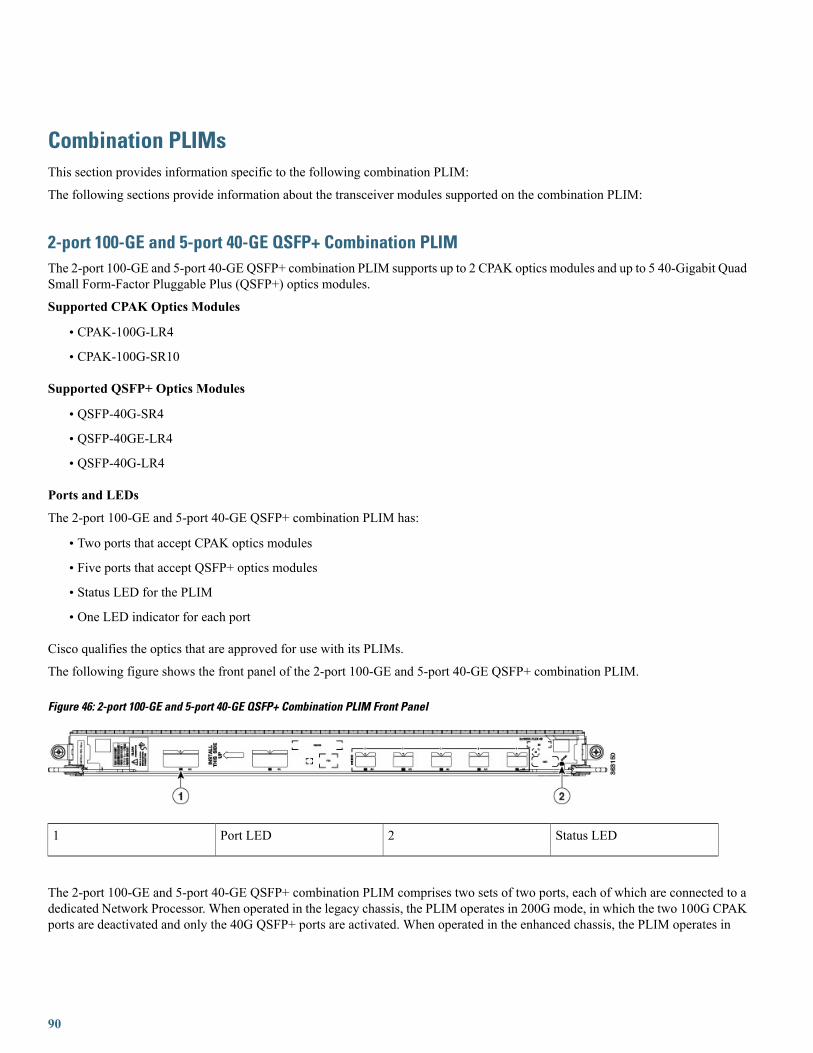
Combination PLIMsThis section provides information specific to the following combination PLIM:
The following sections provide information about the transceiver modules supported on the combination PLIM:
2-port 100-GE and 5-port 40-GE QSFP+ Combination PLIMThe 2-port 100-GE and 5-port 40-GE QSFP+ combination PLIM supports up to 2 CPAK optics modules and up to 5 40-Gigabit QuadSmall Form-Factor Pluggable Plus (QSFP+) optics modules.
Supported CPAK Optics Modules
• CPAK-100G-LR4
• CPAK-100G-SR10
Supported QSFP+ Optics Modules
• QSFP-40G-SR4
• QSFP-40GE-LR4
• QSFP-40G-LR4
Ports and LEDs
The 2-port 100-GE and 5-port 40-GE QSFP+ combination PLIM has:
• Two ports that accept CPAK optics modules
• Five ports that accept QSFP+ optics modules
• Status LED for the PLIM
• One LED indicator for each port
Cisco qualifies the optics that are approved for use with its PLIMs.
The following figure shows the front panel of the 2-port 100-GE and 5-port 40-GE QSFP+ combination PLIM.
Figure 46: 2-port 100-GE and 5-port 40-GE QSFP+ Combination PLIM Front Panel
Status LED2Port LED1
The 2-port 100-GE and 5-port 40-GE QSFP+ combination PLIM comprises two sets of two ports, each of which are connected to adedicated Network Processor. When operated in the legacy chassis, the PLIM operates in 200G mode, in which the two 100G CPAKports are deactivated and only the 40G QSFP+ ports are activated. When operated in the enhanced chassis, the PLIM operates in
90

400G mode, in which all ports (2x100GE ports and 5x40GE ports) are activated. Switching from 400G mode to 200G mode in theenhanced chassis is not supported.
For 40-Gbps to 10-Gbps breakout options, the 40-GE ports only support the SR-4 breakout cable that hasa cylindrical splitter.
Note
In 200G mode, the port numbering is different than 400G mode and starts with 0 for the port that is labeled 2 in 400G mode. Thefaceplate labels therefore include two port numbers for the ports that are active in 200G Mode, as shown in the following figure.
Figure 47: Half of the Front Panel, Showing Two Sets of Port Numbers
The following table describes the PLIM LEDs for the 2-port 100-GE and 5-port 40-GE QSFP+ combination PLIM.
Table 38: 2-Port 100-GE and 5-Port 40GE QSFP+ Combination PLIM LED Descriptions
DescriptionStateLED
PLIM is powered on and operatingcorrectly.
GreenStatus
PLIM is powered on but is initializing.Yellow
PLIM is powered off or power up did notcomplete successfully.
Off
Port is enabled by software and there isa valid link.
GreenPort
PLIM is powered on but port is notenabled by software.
Yellow
PLIM is powered off.Off
Physical Characteristics
• Height—20.6 in (52.2 cm)
• Depth—11.2 in (28.4 cm)
•Width—1.8 in (4.49 cm)
91

•Weight—8.18 lbs (4.0 kg)
• Power consumption—140 W
40-Gigabit QSFP+ Transceiver Module
The 40-Gigabit QSFP+ transceiver module is a hot-swappable, parallel fiber-optical module with four independent optical transmitand receive channels. The QSFP+ transceiver module connects the electrical circuitry of the system with an optical external network.The following figure shows the optical QSFP+ transceiver. The transceiver is used primarily in short reach applications in switches,routers, and data center equipment where it provides higher density than SFP+ modules.
Figure 48: 40-Gigabit QSFP+ transceiver module
40GBASE QSFP+ transceiver body1
Bail-clasp latch2
Electrical connection to the module circuitry3
The following table lists the different 40-Gigabit QSFP+ transceiver module types.
Table 39: 40-Gigabit QSFP+ Transceiver Modules
DescriptionQSFP+ Transceiver ModuleProduct Number
Cisco 40GBASE-SR4 QSFP+ transceiver module for MMF,multi-fiber MPO connector
QSFP-40G-SR4
Cisco 40GBASE-LR4 QSFP+ transceiver module for SMF,duplex LC connector, multi-rate with OTU3 support
QSFP-40G-LR4
Cisco 40GBASE-LR4 QSFP+ transceiver module for SMF,duplex LC connector, 40G Ethernet rate only
QSFP-40GE-LR4
92
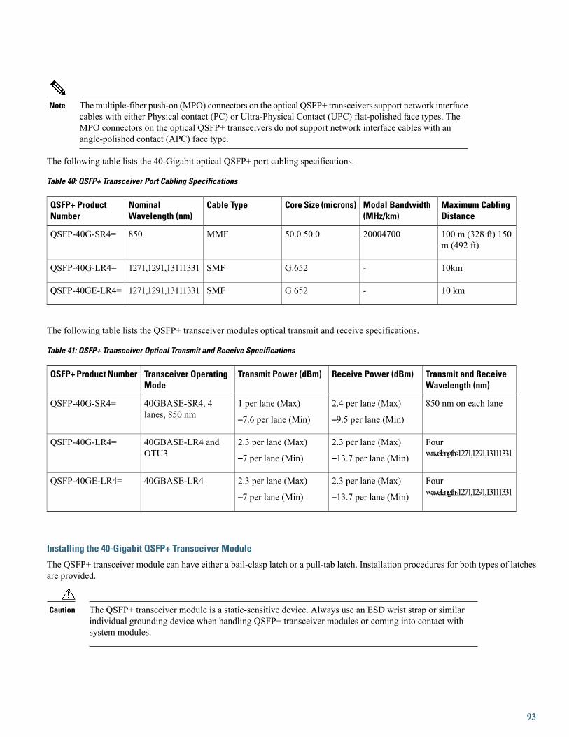
Themultiple-fiber push-on (MPO) connectors on the optical QSFP+ transceivers support network interfacecables with either Physical contact (PC) or Ultra-Physical Contact (UPC) flat-polished face types. TheMPO connectors on the optical QSFP+ transceivers do not support network interface cables with anangle-polished contact (APC) face type.
Note
The following table lists the 40-Gigabit optical QSFP+ port cabling specifications.
Table 40: QSFP+ Transceiver Port Cabling Specifications
Maximum CablingDistance
Modal Bandwidth(MHz/km)
Core Size (microns)Cable TypeNominalWavelength (nm)
QSFP+ ProductNumber
100 m (328 ft) 150m (492 ft)
2000470050.0 50.0MMF850QSFP-40G-SR4=
10km-G.652SMF1271,1291,13111331QSFP-40G-LR4=
10 km-G.652SMF1271,1291,13111331QSFP-40GE-LR4=
The following table lists the QSFP+ transceiver modules optical transmit and receive specifications.
Table 41: QSFP+ Transceiver Optical Transmit and Receive Specifications
Transmit and ReceiveWavelength (nm)
Receive Power (dBm)Transmit Power (dBm)Transceiver OperatingMode
QSFP+ Product Number
850 nm on each lane2.4 per lane (Max)
–9.5 per lane (Min)
1 per lane (Max)
–7.6 per lane (Min)
40GBASE-SR4, 4lanes, 850 nm
QSFP-40G-SR4=
Fourwavelengths1271,1291,13111331
2.3 per lane (Max)
–13.7 per lane (Min)
2.3 per lane (Max)
–7 per lane (Min)
40GBASE-LR4 andOTU3
QSFP-40G-LR4=
Fourwavelengths1271,1291,13111331
2.3 per lane (Max)
–13.7 per lane (Min)
2.3 per lane (Max)
–7 per lane (Min)
40GBASE-LR4QSFP-40GE-LR4=
Installing the 40-Gigabit QSFP+ Transceiver Module
The QSFP+ transceiver module can have either a bail-clasp latch or a pull-tab latch. Installation procedures for both types of latchesare provided.
The QSFP+ transceiver module is a static-sensitive device. Always use an ESD wrist strap or similarindividual grounding device when handling QSFP+ transceiver modules or coming into contact withsystem modules.
Caution
93

To install an QSFP+ transceiver module, follow these steps:
Procedure
Step 1 Attach an ESD wrist strap to yourself and a properly grounded point on the chassis or the rack.Step 2 Remove the QSFP+ transceiver module from its protective packaging.Step 3 Check the label on the QSFP+ transceiver module body to verify that you have the correct model for your network.Step 4 For optical QSFP+ transceivers, remove the optical bore dust plug and set it aside.Step 5 For transceivers equipped with a bail-clasp latch:
a) Keep the bail-clasp aligned in a vertical position.b) Align the QSFP+ transceiver in front of the module’s transceiver socket opening and carefully slide the QSFP+
transceiver into the socket until the transceiver makes contact with the socket electrical connector. (See the followingfigure.)
Step 6 For QSFP+ transceivers equipped with a pull-tab:a) Hold the transceiver so that the identifier label is on the top.b) Align the QSFP+ transceiver in front of the module’s transceiver socket opening and carefully slide the QSFP+
transceiver into the socket until the transceiver makes contact with the socket electrical connector.
Figure 49: Installing the 40-Gigabit QSFP+ Transceiver Module (Optical Transceiver Equipped with a Bail-Clasp Latch Shown)
Step 7 Press firmly on the front of the QSFP+ transceiver with your thumb to fully seat the transceiver in the module’s transceiversocket. (See the following figure.)
94

If the latch is not fully engaged, you might accidentally disconnect the QSFP+ transceiver module.Caution
Figure 50: Seating the 40-Gigabit QSFP+ Transceiver Module (Optical Transceiver Equipped with a Bail-Clasp Latch Shown)
Step 8 For optical QSFP+ modules, reinstall the dust plug into the QSFP+ transceivers optical bore until you are ready to attachthe network interface cable. Do not remove the dust plug until you are ready to attach the network interface cable.
Attaching the Optical Network Cable
Before removing the dust plugs and making any optical connections, follow these guidelines:
• Keep the protective dust plugs installed in the unplugged fiber-optic cable connectors and in the transceiver optical boresuntil you are ready to make a connection.
◦
◦Inspect and clean the MPO connector end faces just before you make any connections. See the Tip following step 2 in thenext procedure for a pointer to a fiber-optic inspection and cleaning white paper.
◦Grasp the MPO connector only by the housing to plug or unplug a fiber-optic cable.
40-Gigabit QSFP+ transceiver modules are keyed to prevent incorrect insertion.Note
95

Themultiple-fiber push-on (MPO) connectors on the optical QSFP+ transceivers support network interfacecables with either physical contact (PC) or ultra-physical contact (UPC) flat polished face types. TheMPOconnectors on the optical QSFP+ transceivers do not support network interface cables with an angle-polishedcontact (APC) face type.
Note
Procedure
Step 1 Remove the dust plugs from the optical network interface cable MPO connectors. Save the dust plugs for future use.Step 2 Inspect and clean the MPO connector’s fiber-optic end faces. See the Tip below for a pointer to a fiber-optic inspection
and cleaning white paper.For complete information on inspecting and cleaning fiber-optic connections, see the Cleaning Fiber-OpticConnectors, on page 70.
Tip
Step 3 Remove the dust plugs from the QSFP+ transceiver module optical bores.Step 4 Immediately attach the network interface cable MPO connectors to the QSFP+ transceiver module.
Removing the 40-Gigabit QSFP+ Transceiver Module
The QSFP+ transceiver module is a static-sensitive device. Always use an ESD wrist strap or similarindividual grounding device when handling QSFP+ transceiver modules or coming into contact withmodules.
Caution
To remove a QSFP+ transceiver, follow these steps:
Procedure
Step 1 For optical QSFP+ transceivers, disconnect the network interface cable from the QSFP+ transceiver connector.Step 2 For QSFP+ transceivers equipped with a bail-clasp latch (See see the following figure, top view):
a) Pivot the bail-clasp down to the horizontal position.b) Immediately install the dust plug into the transceivers optical bore.c) Grasp the sides of the QSFP+ transceiver and slide it out of the module socket.
Step 3 For QSFP+ transceivers equipped with a pull tab latch (See the following figure, bottom view):a) Immediately install the dust plug into the transceiver’s optical bore.b) Grasp the tab and gently pull to release the transceiver from the socket.c) Slide the transceiver out of the socket.
Step 4 Place the QSFP+ transceiver into an antistatic bag.
96

Figure 51: Removing the 40-Gigabit QSFP+ Transceiver Module
How to Remove or Install a PLIMA PLIM provides the data interfaces for the routing system and mates with its associated MSC through the chassis midplane.
This section contains the following procedures:
Removing a PLIMThis section describes how to remove a PLIM from the line card chassis.
The system may indicate a hardware failure if you do not follow proper procedures. Remove or installonly one PLIM at a time. Allow at least 15 seconds for the system to complete the preceding tasks beforeremoving or installing another PLIM.
Caution
Required Tools and Equipment
You need the following tools to remove a PLIM:
• ESD-preventive wrist strap
• Medium (Number 2) Phillips screwdriver
To remove a PLIM, see the following figure, and follow these steps:
97

Procedure
Step 1 Attach an ESD-preventive wrist strap and follow its instructions for use.Step 2 Identify the card to be replaced, and unplug the interface cables connected to the card. Be sure to note the current connections
of the cables to the ports on the PLIM.Because invisible radiation may be emitted from the aperture of the port when no fiber cable is connected,avoid exposure to radiation and do not stare into open apertures. Statement 125
Warning
Step 3 For the 10-GE PLIMs, remove the XENPAK or XFP optics modules from the card and set them aside. See the How toRemove or Install a PLIMCableManagement Bracket, on page 101 section or How to Remove or Install an XFPModule,on page 72 section.
Step 4 Loosen the two captive screws holding the card in place.Step 5 Grasp the two card ejector levers and simultaneously pivot both ejector levers 90 degrees (70 degrees for a newer PLIM)
away from the front edge of the card carrier to unseat the card from the backplane (see the following figure).Step 6 Grasp the cable management bracket and gently pull the PLIM halfway from the slot.Step 7 Slide the card from the slot, using one hand under the PLIM to support and guide it (see the following figure). Avoid
touching the PLIM printed circuit board, components, or any connector pins. Do not lift cards by the cable managementbracket; lift them from the bottom.
Step 8 Place the PLIM directly into an antistatic sack or other ESD-preventive container.Step 9 Insert another PLIM or an impedance carrier into the empty card slot.
98
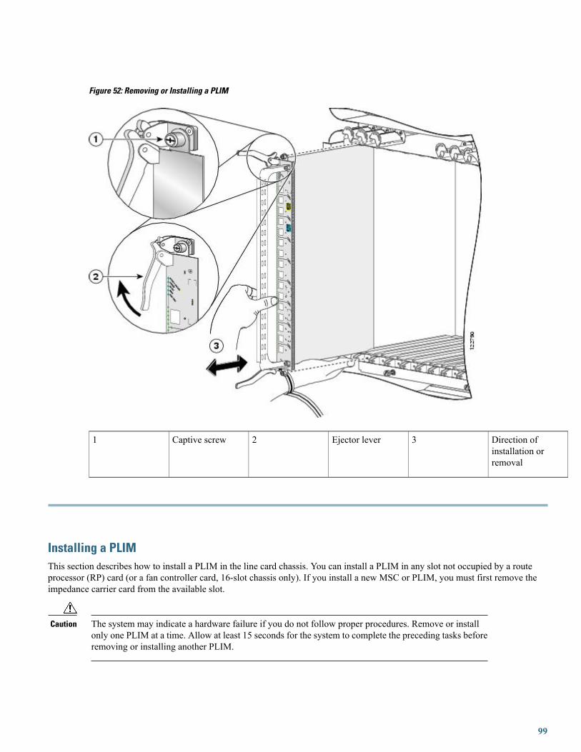
Figure 52: Removing or Installing a PLIM
Direction ofinstallation orremoval
3Ejector lever2Captive screw1
Installing a PLIMThis section describes how to install a PLIM in the line card chassis. You can install a PLIM in any slot not occupied by a routeprocessor (RP) card (or a fan controller card, 16-slot chassis only). If you install a new MSC or PLIM, you must first remove theimpedance carrier card from the available slot.
The system may indicate a hardware failure if you do not follow proper procedures. Remove or installonly one PLIM at a time. Allow at least 15 seconds for the system to complete the preceding tasks beforeremoving or installing another PLIM.
Caution
99

Required Tools and Equipment
You need the following tools and part to install a PLIM:
• ESD-preventive wrist strap
• Medium (Number 2) Phillips screwdriver
• PLIM
Steps
To install a PLIM, see the previous figure, and follow these steps:
Procedure
Step 1 Attach the ESD-preventive wrist strap and follow its instructions for use.Step 2 Remove the PLIM from its antistatic packaging.Step 3 Remove the PLIM impedance carrier from the slot you need to fill and set it aside.
Remove only one impedance carrier and install one PLIM at a time. Be sure to verify that each PLIM is fullyinstalled and secured before installing another card.
Note
Step 4 Grasp the cable management bracket with one hand and place your other hand under the carrier to support and guide thecard into the correct slot. Slide the card halfway into the correct slot. Avoid touching the card circuitry or any connectors.
Step 5 Pivot both card ejector levers so that the openings on the card ejector cams at the top and bottom of the card pass over thetabs on each side of the card cage slot.
Verify that the openings on the card ejector cams pass over the tabs; otherwise, one or both ejector levers mightbind when you attempt to close the ejector levers, thereby damaging or breaking one or both ejector levers.
Caution
Step 6 Continue sliding the card into the card cage slot until the openings on the card ejector cams engage the tabs on each sideof the card cage slot.
Guide pins located on the midplane connector make initial contact with the card connector as you slide a cardinto its slot. After the guide pins make contact, continue pushing on the card carrier until the card ejector leversbegin pivoting forward toward the handle in the card carrier.
Note
Step 7 To seat the card in the midplane connector, grasp both card ejector levers and pivot them inward toward the handle in thecard carrier until they are flush against the front edge of the card carrier.
Step 8 Engage both captive screws on the PLIM, and then tighten the screws.Be sure to engage both captive screws on the PLIM before you begin to tighten the screws; otherwise, thePLIM might not seat properly.
Caution
To ensure adequate space for additional PLIMs, always tighten the captive installation screws on each newlyinstalled PLIM before you insert another PLIM. These screws also prevent accidental removal and provideproper grounding and EMI shielding for the system.
Caution
Step 9 For the 10-GE PLIM, install the XENPAK or XFP optics modules. See the How to Remove or Install a PLIM CableManagement Bracket, on page 101 section or How to Remove or Install an XFP Module, on page 72 section.
Step 10 If this PLIM is new, install the PLIM cable management bracket. See the Removing a PLIM Cable Management Bracket,on page 104 section.
Step 11 Install the interface cables. We recommend that you clean the fiber-optic connections before attaching the cables. Forcleaning instructions, see: http://www.cisco.com/warp/public/127/cleanfiber2.html .
Step 12 If this PLIM is new, configure it for operation. For instructions, see Cisco IOS XR Interface and Hardware ComponentConfiguration Guide and Cisco IOS XR Interface and Hardware Component Command Reference , available at:
100

http://www.cisco.com/univercd/cc/td/doc/product/ioxsoft/iox33/index.html
Because invisible radiation may be emitted from the aperture of the port when no fiber cable is connected,avoid exposure to radiation and do not stare into open apertures. Statement 125
Warning
Verifying the Installation of a PLIMThis section describes how to verify that a PLIM has been properly installed. See the figure showing the front panel of your PLIMfor the locations of the port and Status LEDs on the front panel of the PLIM (see Figure 2: 20-Port 1-GE Flex PLIM Front Panel forthe 20-port 1-GE PLIM with SFP optics modules or see Figure 22: 14-Port 10-GE XFP PLIM front panel for the 14-port 10-GE XFPPLIM).
If a PLIM fails to operate or power up on installation:
• Make sure that the PLIM is seated firmly in the line card chassis slot. One easy way to verify physical installation is to seewhether the front faceplate of the PLIM is even with the fronts of the other PLIMs installed in the card cage.
• Make sure that the corresponding MSC is installed and operating correctly.
• Check whether the ejector levers are latched and that the captive screws are fastened properly. If you are uncertain, unlatch thelevers, loosen the screws, and attempt to reseat the PLIM.
• Determine whether there are any active alarms by looking at the alarm LEDs on the alarm module (16-slot chassis) or the routeprocessor (8-slot or 4-slot chassis). See Cisco CRS-1 Carrier Routing System Line Card Chassis System Description for moreinformation about alarms.
• Examine the power shelves (16-slot chassis) or power distribution units (PDUs) (8-slot and 4-slot chassis) to see whether thechassis, as a whole, is receiving power.
Use the LEDs on the PLIM to verify the correct installation and operation of the card.
How to Remove or Install a PLIM Cable Management BracketCisco CRS chassis include a cable management system that organizes the interface cables entering and exiting the router, keepingthem out of the way and free of sharp bends.
Excessive bending of interface cables can damage the cables.Caution
The cable management system consists of two separate components:
• The line card chassis arrives preinstalled with a horizontal cable management bracket on the front of the chassis and an optionalhorizontal cable management bracket available for the rear of the chassis. The cable management system organizes the interfacecables entering and exiting the different cards, keeping them out of the way and free of sharp bends. See the appropriate CiscoCRS installation guide for more information on the chassis cable management bracket.
• A cable management bracket that attaches to a PLIM.
101

This section describes how to remove and install the two types of PLIM cable management bracket. The following shows the PLIMcable management bracket. Figure 54: PLIM Articulated Cable Management Bracket shows the articulated PLIM cable managementbracket, designed for installing on the 20-port 1-GE FLEX PLIM and the 42-port 1-GE XFP PLIM.
Figure 53: PLIM Cable Management Bracket
Figure 54: PLIM Articulated Cable Management Bracket
102

Note the following:
• The front leg of the articulated PLIM cable management bracket is light gray. The articulated bracket can be moved for easeof cabling or uncabling. Always connect your interface cables starting with the interface at the top of the PLIM and alwaysdisconnect your interface cables starting with the interface at the bottom of the PLIM.
• For details about replacing a SFP from a line card that uses an articulated bracket, see Replacing a SFP on a Line Card that Usesan Articulated Bracket, on page 28.
• You do not have to remove the interface cables from the PLIM cable management bracket. If you are replacing the PLIM, youcan remove the cable management bracket from the PLIM. After you install a new PLIM, you can attach the cable managementbracket to the new PLIM and reattach the interface cables. See the Removing and Installing Fiber-Optic Interface Cables, onpage 66 section.
Do not use the cable management bracket alone as a handle to pull out or push in the PLIM. One handmust be under the PLIM to support its weight when carrying the PLIM. The cable management bracketis designed to hold the interface cables and may break if you use the bracket to push, pull, or carry thePLIM after it is removed from the router.
Caution
Required Tools and EquipmentYou need the following tools and part to remove or install a PLIM cable management bracket:
103

• ESD-preventive wrist strap
• Medium (Number 2) Phillips screwdriver
• PLIM
• PLIM cable management bracket
Removing a PLIM Cable Management BracketTo remove a PLIM cable management bracket, follow the steps below. For an example of a fixed PLIM cable management bracketrefer to Figure 55: PLIMCableManagement Installation and Removal (the 10-GE PLIM is shown in the illustration, but the installationprocedure is similar for all PLIMs). For an example of an articulated PLIM cable management bracket designed for installing on the20-port 1-GE FLEX PLIM refer to Figure 56: Articulated PLIMCableManagement Bracket Installation and Removal (20-Port PLIM)and for an example of an articulated PLIM cable management bracket designed for installing on the 42-port 1-GE XFP PLIM referto Figure 57: Articulated PLIM Cable Management Bracket Installation and Removal (42-Port PLIM).
Procedure
Step 1 Attach an ESD-preventive wrist or ankle strap and follow its instructions for use.Step 2 Note the current interface cable connections to the ports on each PLIM.Step 3 Starting with the interface cable for the bottom port on the PLIM, disconnect the cable from the PLIM interface.
It is not necessary to remove the interface cables from the PLIM cable management bracket. The bracket (withattached cables) can be hooked to the chassis cable management bracket or a bracket on the chassis until a newPLIM is installed.
Note
Step 4 Proceed upward and remove the interface from the Velcro strap on the end of the cable standoff (see callout 2 on Figure55: PLIMCableManagement Installation andRemoval, Figure 56: Articulated PLIMCableManagement Bracket Installationand Removal (20-Port PLIM), or Figure 57: Articulated PLIM Cable Management Bracket Installation and Removal(42-Port PLIM)). Avoid any tight twists or sharp bends in the cable.
104

Figure 55: PLIM Cable Management Installation and Removal
PLIM cable managementbracket
3Chassis cable managementtray
1
Fiber cable4Velcro straps2
105

Figure 56: Articulated PLIM Cable Management Bracket Installation and Removal (20-Port PLIM)
PLIM cable managementbracket
3Chassis cable managementtray
1
Fiber cable4Velcro straps2
106
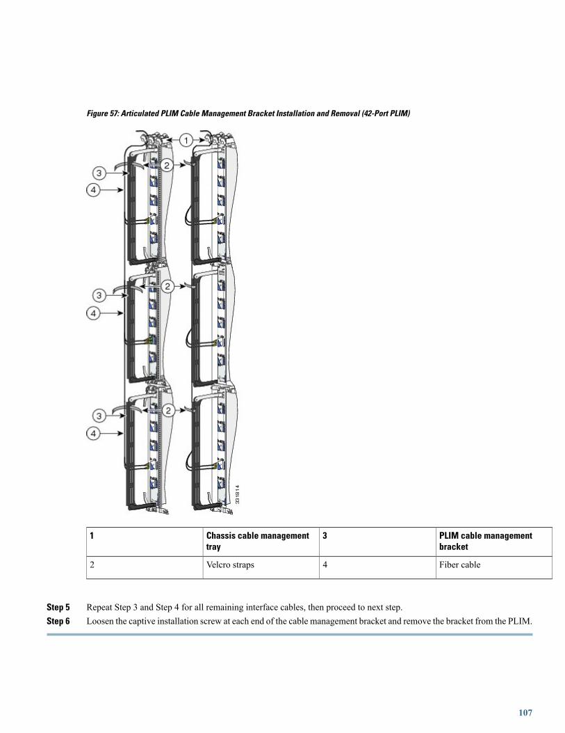
Figure 57: Articulated PLIM Cable Management Bracket Installation and Removal (42-Port PLIM)
PLIM cable managementbracket
3Chassis cable managementtray
1
Fiber cable4Velcro straps2
Step 5 Repeat Step 3 and Step 4 for all remaining interface cables, then proceed to next step.Step 6 Loosen the captive installation screw at each end of the cable management bracket and remove the bracket from the PLIM.
107

Installing a PLIM Cable Management BracketTo install a PLIM cable management bracket, follow these steps:
Procedure
Step 1 Attach an ESD-preventive wrist or ankle strap and follow its instructions for use.Step 2 Attach the PLIM cable management bracket to the PLIM as follows:
a) Position the cable management bracket over the front of the PLIM faceplate.When you are installing the articulated PLIM cable management bracket, ensure that the pin next to the captivescrew goes into the proper hole before you attempt to tighten the captive screws to secure the bracket to thePLIM.
Note
b) Insert and tighten the captive screws to secure the bracket to the PLIM.c) Starting with the bottom port on the PLIM, connect each interface cable to the intended port.
Step 3 Carefully wrap the cables with the supplied Velcro strap (refer to callout 2 on Figure 55: PLIM Cable ManagementInstallation and Removal, Figure 56: Articulated PLIM Cable Management Bracket Installation and Removal (20-PortPLIM), or Figure 57: Articulated PLIM Cable Management Bracket Installation and Removal (42-Port PLIM)). Avoidany tight twists or sharp bends in the cable.
Before You Remove or Install a Transceiver ModuleReview the following sections carefully before you remove or install any type of transceiver module:
Safety GuidelinesBefore you perform any procedure in this document, review the safety guidelines in this section to avoid injuring yourself or damagingthe equipment. See the Laser Safety, on page 112 section.
The following guidelines are for your safety and to protect equipment. The guidelines do not include all hazards. Be alert.
Review the safety warnings listed in Regulatory Compliance and Safety Information for the Cisco CRS-1Carrier Routing System before installing, configuring, or troubleshooting any installed card.
Note
• Never attempt to lift an object that might be too heavy for you to lift by yourself.
• Keep the work area clear and dust free during and after installation. Do not allow dirt or debris to enter into any laser-basedcomponents.
• Keep tools and router components away from walk areas.
• Do not wear loose clothing, jewelry, and other items that could get caught in the router while working with OIMs, SFCs, andtheir associated components.
• Use Cisco equipment in accordance with its specifications and product-usage instructions.
• Do not work alone if potentially hazardous conditions exist.
108

• Make sure your installation follows national and local electrical codes: in the United States, National Fire Protection Association(NFPA) 70, United States National Electrical Code; in Canada, Canadian Electrical Code, part I, CSA C22.1; in other countries,International Electrotechnical Commission (IEC) 60364, part 1 through part 7.
• Connect only a DC power source that follows the safety extra-low voltage (SELV) requirements in UL/CSA/IEC/EN 60950-1and AS/NZS 60590 to the FCC DC-input power system.
• Make sure that you have a readily accessible two-poled disconnect device incorporated in the fixed wiring of an LCC configuredwith the DC-input power system.
• The LCC requires short-circuit (overcurrent) protection to be provided as part of the building installation.
Preventing Electrostatic DischargeElectrostatic discharge (ESD) damage, which can occur when electronic cards or components are improperly handled, results incomplete or intermittent failures. We recommend that you use an ESD-preventive strap whenever you handle network equipment orcomponents.
Following are guidelines for preventing ESD damage:
• Always use an ESD-preventive wrist or ankle strap, and ensure that it makes good skin contact. Connect the equipment end ofthe connection cord to an ESD connection socket on the router or a bare metal surface on the chassis.
• Handle a card by its ejector levers, when applicable, or metal carrier only; avoid touching the board or connector pins.
• Place a removed card component side up on an antistatic surface or in a static-shielding bag. If you plan to return the componentto the factory, immediately place it in a static-shielding bag.
• Avoid contact between the card and clothing. The wrist strap protects the board only from ESD voltage on the body; ESDvoltage on clothing can still cause damage.
Guidelines for Card Installation and RemovalGuidelines for card installation and removal include the following:
• Online insertion and removal (OIR) is supported, enabling you to remove and install cards while the router is running. OIR isseamless to users on the network, maintains all routing information, and ensures session preservation. Notifying the softwareor resetting the power is not required. However, you have the option of using the shutdown command before removing a card.
• Each PLIM and its corresponding MSC function as a pair. If either card is removed, the other card is essentially powered down(although the router can still identify and inventory the cards).
109

• PLIMs in the line card chassis are attached to the chassis by way of a pair of ejector levers and captive screws. The two ejectorlevers are used to release the PLIM from its midplane connector. The ejector levers and captive screws are located on the upperand lower ends of the faceplate of the card (see the following figure).
Figure 58: Ejector Levers and Captive Screws
Ejector lever2Captive screw1
When you remove a PLIM, always use the ejector levers to ensure that the connector pins disconnect fromthe midplane in the sequence expected by the router.The router can indicate a hardware failure if you donot follow proper procedures. Remove or install only one card at a time. Wait at least 15 seconds beforeremoving or installing another card.
Caution
110

About PLIM Impedance CarriersA PLIM impedance carrier must be installed in each empty PLIM slot in the Cisco CRS chassis (see the following figure). Theimpedance carrier preserves the integrity of the chassis and is required for EMI compliance and proper cooling in the chassis.
Figure 59: PLIM Impedance Carrier
Regulatory, Compliance, and Safety InformationThis section contains information on laser safety.
111

For other regulatory, compliance, and safety information, including translated safety warnings, see the Regulatory Compliance andSafety Information for the Cisco CRS-1 Carrier Routing System publication.
Laser SafetyDo not stare into operational transceiver module ports. The following laser warning applies:
Because invisible laser radiation may be emitted from the aperture of the port when no cable is connected,avoid exposure to laser radiation and do not stare into open apertures. Statement 70
Warning
Obtaining Documentation and Submitting a Service RequestFor information on obtaining documentation, using the Cisco Bug Search Tool (BST), submitting a service request, and gatheringadditional information, seeWhat's New in Cisco Product Documentation, at: http://www.cisco.com/c/en/us/td/docs/general/whatsnew/whatsnew.html.
Subscribe toWhat's New in Cisco Product Documentation, which lists all new and revised Cisco technical documentation as an RSSfeed and delivers content directly to your desktop using a reader application. The RSS feeds are a free service.
112

THE SPECIFICATIONS AND INFORMATION REGARDING THE PRODUCTS IN THIS MANUAL ARE SUBJECT TO CHANGE WITHOUT NOTICE. ALL STATEMENTS,INFORMATION, AND RECOMMENDATIONS IN THIS MANUAL ARE BELIEVED TO BE ACCURATE BUT ARE PRESENTED WITHOUT WARRANTY OF ANY KIND,EXPRESS OR IMPLIED. USERS MUST TAKE FULL RESPONSIBILITY FOR THEIR APPLICATION OF ANY PRODUCTS.
THE SOFTWARE LICENSE AND LIMITEDWARRANTY FOR THE ACCOMPANYING PRODUCT ARE SET FORTH IN THE INFORMATION PACKET THAT SHIPPED WITHTHE PRODUCT AND ARE INCORPORATED HEREIN BY THIS REFERENCE. IF YOU ARE UNABLE TO LOCATE THE SOFTWARE LICENSE OR LIMITED WARRANTY,CONTACT YOUR CISCO REPRESENTATIVE FOR A COPY.
The Cisco implementation of TCP header compression is an adaptation of a program developed by the University of California, Berkeley (UCB) as part of UCB's public domain versionof the UNIX operating system. All rights reserved. Copyright © 1981, Regents of the University of California.
NOTWITHSTANDINGANYOTHERWARRANTYHEREIN, ALL DOCUMENT FILES AND SOFTWARE OF THESE SUPPLIERS ARE PROVIDED “AS IS"WITH ALL FAULTS.CISCO AND THE ABOVE-NAMED SUPPLIERS DISCLAIM ALL WARRANTIES, EXPRESSED OR IMPLIED, INCLUDING, WITHOUT LIMITATION, THOSE OFMERCHANTABILITY, FITNESS FORA PARTICULAR PURPOSEANDNONINFRINGEMENTORARISING FROMACOURSEOFDEALING, USAGE, OR TRADE PRACTICE.
IN NO EVENT SHALL CISCO OR ITS SUPPLIERS BE LIABLE FOR ANY INDIRECT, SPECIAL, CONSEQUENTIAL, OR INCIDENTAL DAMAGES, INCLUDING, WITHOUTLIMITATION, LOST PROFITS OR LOSS OR DAMAGE TO DATA ARISING OUT OF THE USE OR INABILITY TO USE THIS MANUAL, EVEN IF CISCO OR ITS SUPPLIERSHAVE BEEN ADVISED OF THE POSSIBILITY OF SUCH DAMAGES.
Any Internet Protocol (IP) addresses and phone numbers used in this document are not intended to be actual addresses and phone numbers. Any examples, command display output, networktopology diagrams, and other figures included in the document are shown for illustrative purposes only. Any use of actual IP addresses or phone numbers in illustrative content is unintentionaland coincidental.
Cisco and the Cisco logo are trademarks or registered trademarks of Cisco and/or its affiliates in the U.S. and other countries. To view a list of Cisco trademarks, go to this URL: http://www.cisco.com/go/trademarks. Third-party trademarks mentioned are the property of their respective owners. The use of the word partner does not imply a partnershiprelationship between Cisco and any other company. (1110R)
© 2016 Cisco Systems, Inc. All rights reserved.

Europe HeadquartersAsia Pacific HeadquartersAmericas HeadquartersCisco Systems International BVAmsterdam, The Netherlands
Cisco Systems (USA) Pte. Ltd.Singapore
Cisco Systems, Inc.San Jose, CA 95134-1706USA
Cisco has more than 200 offices worldwide. Addresses, phone numbers, and fax numbers are listed on theCisco Website at www.cisco.com/go/offices.