cii & bee data center book
TRANSCRIPT

8/12/2019 CII & BEE Data Center Book
http://slidepdf.com/reader/full/cii-bee-data-center-book 1/250

8/12/2019 CII & BEE Data Center Book
http://slidepdf.com/reader/full/cii-bee-data-center-book 2/250

8/12/2019 CII & BEE Data Center Book
http://slidepdf.com/reader/full/cii-bee-data-center-book 3/250

8/12/2019 CII & BEE Data Center Book
http://slidepdf.com/reader/full/cii-bee-data-center-book 4/250
Disclaimer
© 2010, Bureau of Energy Efficiency (BEE), Ministry of Power, Government of India
All rights reserved. No part of this publication may be reproduced, stored in a retrieval system, or
transmitted, in any form or by any means electronic, mechanical, photocopying, recording or otherwise,
without the prior written permission from Bureau of Energy Efficiency (BEE), Ministry of Power-
Government of India.
While every care has been taken in compiling this Manual, neither BEE nor Confederation of Indian
Industry (CII) accepts any claim for compensation, if any entry is wrong, abbreviated, cancelled, omitted
or inserted incorrectly either as to the wording, space or position in the Manual. The Manual is only an
attempt to create awareness on energy conservation and sharing of best practices being adopted in
India as well as abroad.
“Manual on Energy Efficiency guidelines and Best Practices in Indian Datacenters” was supported by
a grant from Bureau of Energy Efficiency (BEE), Ministry of Power, Government of India to promote
Energy Efficiency initiative in Indian Datacenters.
Published by Bureau of Energy Efficiency (BEE), Ministry of Power, Government of India.

8/12/2019 CII & BEE Data Center Book
http://slidepdf.com/reader/full/cii-bee-data-center-book 5/250

8/12/2019 CII & BEE Data Center Book
http://slidepdf.com/reader/full/cii-bee-data-center-book 6/250
8/12/2019 CII & BEE Data Center Book
http://slidepdf.com/reader/full/cii-bee-data-center-book 7/250
Confederation of Indian Industry Energy Efficiency Guidelines and Best Practices in Indian Datacenters V
Bureau of Energy Efficiency
Acknowledgement
A nation of a billion plus is on the rise with a sustained economic growth of more than 8%
and energy is considered to be the lifeblood of its success. With the increasing national energy
consumption blended with the Climate Change issues which actually intensify our focus on
energy efficiency. The services sector has been experiencing a significant growth in India and
a major part of this is attributable to the IT sector. The worldwide explosion of data in an
electronic form has resulted in establishment of mega Data Centers.
Leapfrogging with a low-carbon-economy, Indian IT and other stakeholders has to enhance
energy competitiveness and reduce carbon footprints.
Energy Efficiency Guidelines and Best practices in Indian Datacenter: A sourcebook
for Indian Datacenter industry is developed under the initiative of Bureau of Energy Efficiency
(BEE) and Confederation of Indian Industry (CII).
CII wish to thank all the stakeholders of Datacenter for their generous assistance in the execution
of the project. The guidance of BEE and valuable assistance of members has facilitated CII in
developing, compiling and reviewing of the document.
We are indebted to Dr Ajay Mathur, Director General, BEE and Mr Sanjay Seth, Energy
Economist, BEE for providing extensive guidance and review throughout the preparation ofthe document.
The steering committee, Core Group Members and other experts worked closely to develop
this comprehensive report.
On behalf of CII, it is our pleasure to thank all individual Core group Chairman, the members
of the steering committee and Core-Groups and stakeholders for their contribution towards
the finalization of this document.
CII highly appreciates the contribution of the following steering committee members for the
preparation of this document.
Mr Aravind Sitaraman, Cisco Systems (India) Private Limited
Mr Ashish Rakheja, Spectral Services Consultants Pvt Ltd
Prof R Balasubramaniam, Indian Institute of Technology, New Delhi
Mr Deepak Bhardwaj, Texas Instruments (India) Private Limited

8/12/2019 CII & BEE Data Center Book
http://slidepdf.com/reader/full/cii-bee-data-center-book 8/250
Mr R Muralidharan Iyengar, Blue Star Limited
Mr Pramod Deshmukh, Hewlett Packard India Sales Pvt Ltd
Mr Sandeep Nair, Emerson Network Power (India) Pvt Ltd
Mr Sanjesh Gupta, Wipro Infotech
Dr Sathish Kumar, USAID ECO-III Project, IRG
Mr Srinivas Chebby, American Power Conversion (APC)
Mr Sanjeev Gupta, IBM India Pvt Ltd
Ms Shaheen Meeran, Schnabel, DC Consultant India
Mr Sudhir Shetty, Intel Technology India Pvt Ltd
Mr Sujeet Deshpande, Tata Communications Ltd
Mr. Suresh Balakrishnan, STULZ-CHSPL India Pvt Ltd.
Mr Tanmoy Chakrabarty, Tata Consultancy Services
Mr Uday Bhaskarwar, Infosys Technologies Ltd
CII would like to thank and acknowledge Dr Dale Sartor, Applications team, Lawrence Berkeley
National Laboratory for his valuable time and sharing the experience with all the members of
the project.
CII thanks the following companies for their participation and support in the field visit and
sharing their best practices.
Cadence Design Systems (I) Private Limited
Cisco Systems (India) Private Limited
Ctrl S Datacenters Limited Hewlett Packard India Sales Private Limited
Infosys Technologies Limited
Intel Technology India Private Limited
Sun Microsystems India Private Limited
Wipro Technologies
In conclusion, CII thanks all the members, participating companies and experts who had
contributed for this initiative.

8/12/2019 CII & BEE Data Center Book
http://slidepdf.com/reader/full/cii-bee-data-center-book 9/250
Confederation of Indian Industry Energy Efficiency Guidelines and Best Practices in Indian Datacenters VII
Bureau of Energy Efficiency
About the Manual
This manual contains the following,
Information about the latest trends & technologies in Datacenters and its associated systems=
The best practices adopted in various Datacenters for improving energy efficiency levels. Case studies=
elucidating the technical details and the financial benefits of adopting certain measures for higher
energy efficiency
Guidelines for setting up Energy Efficient Datacenteres=
Key indicators to assess the performance of existing systems=
Information to set section-wise targets for energy conservation goals=
How to use this manual
Each chapter in this manual focuses on energy efficiency in particular areas such as Datacenter=
cooling, IT peripherals, electrical system, etc. Hence, the chapters can be read independently, and
or in random order
Best Practices presented in this Manual have been proven to enhance the energy efficiency of=
the existing systems described in the Case Studies. However they should be suitably adapted and
fine-tuned for implementation in other Datacenters, outside the settings described
The technologies mentioned and discussed in the Manual are the current ones at the time of=
publication. As newer technologies emerge, their suitability to existing and future projects needs to
be studied

8/12/2019 CII & BEE Data Center Book
http://slidepdf.com/reader/full/cii-bee-data-center-book 10/250

8/12/2019 CII & BEE Data Center Book
http://slidepdf.com/reader/full/cii-bee-data-center-book 11/250
Confederation of Indian Industry Energy Efficiency Guidelines and Best Practices in Indian Datacenters IX
Bureau of Energy Efficiency
Contents
No. Description Page No.
Foreword
Executive Summary
Introduction
Chapter 1 Datacenter Overview 1
1.0 Introduction 3
1.1 Datacenter Growth trend 3
1.2 Present scenario & future growth 3
1.3 Source of Datacenter Power Consumption 4
1.4 Classification of Datacenters 4
1.5 TIA - 942 Standards 5
1.6 Datacenter Tiers 6
1.7 Datacenter Architecture 8
Chapter 2 Datacenter Electrical System 9
2.0 Introduction 13
2.1 Electrical Requirements of Datacenter 13
2.2 Power flow in a Datacenter 14
2.3 Diesel Generator Set 15
2.4 Transformer 18
2.5 Transfer Switch arrangement 20
2.6 Transient Voltage Surge Suppressor (TVSS) 21
2.7 Distribution Board 25
2.8 Uninterrupted Power Supply (UPS) System 25
2.9 Power Distribution Units 34
2.10 Static Switch 36
2.11 Advanced Power strip 36
2.12 Energy saving Opportunities in Electrical Systems37
Case Study 1 Power Quality improvement in a Datacenter by installingHarmonic Filters
43
Case Study 2 Energy Efficiency improvement in UPS Systems by LoadingOptimization
46
Case Study 3 Energy Efficiency improvement in Lighting System byreplacing fluorescent lamps with Light Emitting Diode (LED)Lamps
50

8/12/2019 CII & BEE Data Center Book
http://slidepdf.com/reader/full/cii-bee-data-center-book 12/250
Bureau of Energy Efficiency
X Energy Efficiency Guidelines and Best Practices in Indian Datacenters Confederation of Indian Industry
Chapter 3 Datacenter Cooling 53
3.1 Introduction 57
3.2 Cooling process in a Datacenter 57
3.3 Critical Cooling configuration and its components 59
3.4 Precision Air Conditioner (PAC) 61
3.5 Criteria for cooling system design 63
3.6 Process of cooling in a Datacenter 65
3.7 Determining heat output of a system 66
3.8 Cable Management 66
3.9 Energy Conservation measures in the Air-Conditioning System 66
Case Study 4 Potential benefits of economizer in cooling system 81
Case Study 5 Introduction of Intelligent Controller for multiple CRAC unitsystem
85
Case Study 6 Benefits of Electronically Commutted (EC) fans for
varying air requirement
88
Case Study 7 Potential benefits of hot aisle / cold aisle containment 91
Case Study 8 Introduction of systematic cable management for better air
distribution in raised floor system
95
Case Study 9 Benefits of humidity control for energy efficiency in
Datacenter
97
Case Study 10 Benefits of redefining Inlet conditions for energy efficiency
in Datacenter
100
Case Study 11 Benefits of water cooled cabinets in cooling system 105
Case Study 12 Operate IT equipment cooling system at a higher
temperature difference
107
Case Study 13 CFD simulation for enhanced Datacenter productivity 109
Case Study 14 Thermal storage system for emergency
cooling requirements
111
Chapter 4 IT Equipment and Peripherals 113
4.1 Introduction 117
4.2 Server power consumption 118
4.3 Challenges in critical cooling 119
4.4 Strategies for reducing energy consumption 119
4.5 Energy conservation measures in IT equipment 128

8/12/2019 CII & BEE Data Center Book
http://slidepdf.com/reader/full/cii-bee-data-center-book 13/250
Confederation of Indian Industry Energy Efficiency Guidelines and Best Practices in Indian Datacenters XI
Bureau of Energy Efficiency
Case study 15 Benefits of accelerated server refresh strategy 134
Case study 16 Enterprise computing performance improvement throughconsolidation of datacenters
137
Case study 17 Network virtualization for performance Improvement 139
Case study 18 Effective storage utilization to optimize datacenter
operational cost
141
Case study 19 Infrastructure efficiency improvement in avirtualized environment
144
Chapter 5 Operation and Maintenance 151
5.1 Significance of Operation and Maintenance 155
5.2 Technical Documentation & Internal Training 155
5.3 Manpower and Training 156
5.4 Housekeeping 156
5.5 Preventive Maintenance 1575.6 Breakdown Maintenance 157
5.7 Condition Based Monitoring 158
5.8 Capacity vs. Utilization 158
5.9 Metering & Calibration 159
5.10 Routine Audits 159
5.11 Change Management 160
5.12 Management Information System (MIS) 164
Case study 20 Capturing the benefits through metering and monitoringsystem for effective energy management
171
Chapter 6 Role of Management in Datacenter Energy Efficiency 177
6.0 Introduction 179
6.1 Role of management 179
6.2 Energy Management Strategies 180
6.3 Components of energy management 181
6.4 Conclusion 183
Annexure 1 Grounding 185Annexure 2 Air Management & Air Distribution Metrics 186
Annexure 3 Twenty Seven things to meet "Twenty Four by forever" expectations 187
Annexure 4 Datacenter Benchmarking Guide 190
Annexure 5 List of Energy Saving Opportunities in Datacenter 197
References 199
Terms & Definitions 202

8/12/2019 CII & BEE Data Center Book
http://slidepdf.com/reader/full/cii-bee-data-center-book 14/250

8/12/2019 CII & BEE Data Center Book
http://slidepdf.com/reader/full/cii-bee-data-center-book 15/250
Confederation of Indian Industry Energy Efficiency Guidelines and Best Practices in Indian Datacenters XIII
Bureau of Energy Efficiency
Executive Summary
In the past decade, India has witnessed an exponential increase in the demand for digital storage, from
1 petabyte in 2001 to more than 34 petabytes by 2007. They also continue to grow at a compounded
rate of 25-30%.
Datacenter growth is driven by increasing requirements from the sectors such as financial institutions,
telecom operators, manufacturing and services. While large financial institutions and telecom companies
are likely to build captive Datacenters for hosting their growing data storage needs, Datacenter service
providers are expected to invest significantly to multiply their capacities, so as to fulfill the demand
arising from small and midsize users.
Datacenter is highly energy intensive. With the increasing energy cost, the increase in operational cost
is inevitable. Therefore it becomes necessary to reduce the energy consumption to offset the increasing
operational cost and to maintain competitiveness. Hence the Datacenters in India need to incorporate
innovative designs for energy efficiency and embrace the concept of “Green IT” for sustained growth.
Existing Datacenters need to adopt the best practices in design, operation and maintenance to achieve
operational excellence. New datacenters have to adopt the energy efficiency measures by design. The
objective of this manual is to identify and disseminate the best practices followed in Indian Datacenters
as well as provide guidelines on incorporating energy efficiency aspects at design stage for new
datacenter.
The Bureau of Energy Efficiency (BEE), Ministry of Power, Govt of India assigned CII the task of identifying the
best practices on Energy efficiency adopted in Datacenters and publishing it in the form of a manual.
Under the leadership of Dr Ajay Mathur, Director General, BEE a steering committee comprising of various
stakeholders like Datacenter Users, Datacenter designers, IT equipment specialists, IT Service Providers,
Datacenter cooling & Electrical equipment suppliers, and Datacenter Consultants was formed.
Four Core groups focusing on four major areas (Electrical accessories, Critical Cooling (HVAC),
IT peripherals and Operation & maintenance) visited more than ten Datacenters across the country to
identify and bring out the best practices adopted as well as develop guidelines for new datacenter.
The manual has detailed out three major components of a Datacenter, and also focused on Operation
and Maintenance aspects of the same as individual chapters. The chapters brief on the basic functionof respective area and focus on energy saving measures supported with case studies.
Electrical system/Power - Power management is emerging as a key tool to reduce the Total Cost=
of Ownership (TCO) and increase the return on investment on infrastructure costs. The chapter
includes the energy saving opportunities through fine-tuning of UPS loading, transformer loading
and installation of harmonic filters. Emerging technologies such as LED lighting, Modular UPS
system and Rotary UPS system are also covered

8/12/2019 CII & BEE Data Center Book
http://slidepdf.com/reader/full/cii-bee-data-center-book 16/250
Bureau of Energy Efficiency
XIV Energy Efficiency Guidelines and Best Practices in Indian Datacenters Confederation of Indian Industry
Critical cooling system - Over the years, the increase in processor densities have led to increased=
power & intensity of cooling. This is driving the datacenter market, towards innovative cooling
techniques that can manage excessive heat generated due to increased processor densities. This
manual highlights, in detail, various technologies and strategies that will help in achieving optimum
cooling efficiency in a Datacenter. Emerging technologies such as cooling system economizer,
thermal storage system, and water cooled systems are discussed in detail
IT peripherals - With increasing levels of complexity involved in deploying IT solutions, Datacenter=
managers are increasingly looking for solutions that are more intelligent, in order to achieve energy
efficiency and manage key resources. Virtualization in Datacenter offers various benefits like increased
resource utilization, decreased power and cooling consumption, faster provisioning, and saving in
space requirements. The chapter covers the energy saving opportunities through adoption of high
density servers, virtualization of servers & network component, optimization of storage utilization,
and infrastructure efficiency improvement in a virtualized environment
Operation and Maintenance - With companies relying significantly on IT infrastructure, network=
downtime has a severe impact on its business. As a result, continuous operation of Datacenter
has become extremely vital. The chapter discusses the best practices related to operation and
maintenance which helps in reduction of downtime in a datacenter
More than twenty best practices have been identified and are detailed in the individual chapters of the manual.
The following best practices identified which offer high replication potential in the Indian Datacenters.
These best practices have been discussed in detail in the manual.
1. Power quality improvement in Datacenter by installing harmonic filters2. Energy efficiency improvement in UPS system by loading optimization
3. Deployment of Hot aisle/cold aisle containment for enhanced air management
4. Introduction of Intelligent controller for multiple Computer Room Air-conditioner (CRAC) unit
system.
5. Operation of IT equipment cooling system at a higher temperature difference
6. Installation of Thermal storage system for emergency cooling requirement
7. Deployment of accelerated server refresh strategy for IT performance improvement
8. Infrastructure efficiency improvement in a virtualized environment9. Effective utilization of storage system to minimize Datacenter operation cost
10. Installation of metering and monitoring for effective energy management
The following are the few emerging technologies which offer high replication potential and can be
incorporated by design in newer datacenters.
1. Expansion of Datacenter capacity with water cooled cabinets

8/12/2019 CII & BEE Data Center Book
http://slidepdf.com/reader/full/cii-bee-data-center-book 17/250
Confederation of Indian Industry Energy Efficiency Guidelines and Best Practices in Indian Datacenters XV
Bureau of Energy Efficiency
2. Installation of cooling system economizer
3. Improvement of Energy efficiency in lighting system by replacing fluorescent lamps with
Light Emitting Diode (LED) Lamps
4. Installation of Rotary Uninterruptible power supply (Rotary UPS)
Typically, for a conventional datacenters with operating Power Usage Effectiveness (PUE) of 2.0, theminimum energy saving potential by adoption of latest technologies is between 25 to 30%.
The table* below indicates the impact of various energy saving technologies on the overall energy saving
potential in a Datacenter.
Energy saving technology Percentage impact in overall saving potential
Server virtualization 40%
More power efficient servers 20%
More efficient facilities infrastructure
(e.g. CRACs, PDUs, etc)
7%
More power efficient storage system 6%
More power efficient network equipment 5%
Data storage management technologies 5%
Server or PC power management software 4%
Use of alternative or renewable energy 4%
Tiered storage 4%
Other 5%
This manual is a guideline and compilation of best practices & efficient technologies for incorporating
energy management in Datacenters. The adoption of these best practices and technologies would
enable achievement of better energy efficiency.
The manual also forms a critical part of the overall efforts of Bureau of Energy Efficiency and CII,
towards reducing energy intensity of the Indian economy through adoption of energy efficiency practices
involving all stakeholders.
* Source: dotnet developer’s journal

8/12/2019 CII & BEE Data Center Book
http://slidepdf.com/reader/full/cii-bee-data-center-book 18/250

8/12/2019 CII & BEE Data Center Book
http://slidepdf.com/reader/full/cii-bee-data-center-book 19/250
Confederation of Indian Industry Energy Efficiency Guidelines and Best Practices in Indian Datacenters XVII
Bureau of Energy Efficiency
Introduction
India being the hub of IT activities, the increasing IT business process outsource from foreign countries
has resulted in phenomenal growth of Datacenters in India. The total datacenter capacity in India is
growing at a rapid pace and is expected to exceed 5.1 million square feet by 2012*, which translates
to a compounded Annual Growth Rate of 25-30% in IT businesses.Datacenters are highly energy intensive which implies high cost on the organization for its operation.
Increasing energy cost imposes tremendous pressure on the developers for energy efficient Datacenters by
design. It also compels the users to design and operate their Datacenters in an energy efficient manner.
Energy efficiency in Datacenters offers three fold benefits:
1. Increased national availability of energy
2. Reduction in operating costs
3. Enhanced efficiency in datacenter design & operation leading to climate change mitigation
With this background, Bureau of Energy Efficiency (BEE) - an independent body working under ministry
of power, government of India has taken an initiative to bring out best operating practices that would
result in energy efficiency and design guidelines for Datacenters.
BEE had earlier formulated Energy Conservation Building Code (ECBC) to promote energy efficiency in
commercial building sector. The code has been well received across the country. Subsequent to ECBC,
BEE has now brought out a Manual on best operating practices and Design guidelines for Energy
Efficiency in Indian Datacenters.
The manual has been developed by Confederation of Indian Industry under the guidance of BEE
and the steering committee. The steering committee has been formed under the chairmanship of
Dr Ajay Mathur, Director General, BEE to assist CII in executing the project.
Steering committee
A steering committee was constituted comprising of various stake holders such as Datacenter designers,
IT specialists, Service providers, HVAC & Electrical equipment suppliers, Consultants, Users & Experts.
Individual core groups were formed to focus on the four major areas of the Datacenter. The core
groups have regularly consulted Mr. Sanjay Seth, Energy Economist, BEE for execution of the project.
Core group Chairman
1. Electrical system Mr Dhiman Ghosh Emerson Network Power
2. Critical cooling Mr Ashish Rakheja Spectral Services consultants Pvt. Ltd.
3. IT Peripherals and systems Mr Chandrashekhar Appanna Cisco Systems, Inc.
4. Operations & Maintenance Mr Sudeep Palanna Texas Instruments
*Source : Gartner Inc.

8/12/2019 CII & BEE Data Center Book
http://slidepdf.com/reader/full/cii-bee-data-center-book 20/250
8/12/2019 CII & BEE Data Center Book
http://slidepdf.com/reader/full/cii-bee-data-center-book 21/250
Chapter 1
Datacenter Overview

8/12/2019 CII & BEE Data Center Book
http://slidepdf.com/reader/full/cii-bee-data-center-book 22/250

8/12/2019 CII & BEE Data Center Book
http://slidepdf.com/reader/full/cii-bee-data-center-book 23/250
Confederation of Indian Industry Energy Efficiency Guidelines and Best Practices in Indian Datacenters 3
Bureau of Energy Efficiency
1.0.0 Introduction
As the trend shifts from paper-based to digital information management, Datacenters have
become common and essential to the functioning of business systems. A Datacenter is a
facility that has concentrated depository of various equipment such as servers, data storage
devices, network devices etc. Collectively, this equipment processes, stores, and transmitsdigital information and is known as Information Technology (IT) equipment.
Fundamentally, the Datacenter is a physical place that houses a computer network's most critical
systems, including backup power supplies, air conditioning, and security applications.
1.1.0 Datacenter growth trend
The Datacenter industry is in the midst of a major growth. The increasing reliance on digital
data is driving a rapid increase in the number and size of Datacenters. This growth is the
result of several factors, including growth in the use of internet media and communications
and growth in the need for storage of enormous digital data. For example, Internet usage
is increasing at approximately 10 percent per year worldwide (Source : comScore Networks
2007) and has directly fuelled the growth of Datacenters.
From simple data storage to a complicated global networking, Datacenters play a significant
role and have become an integral part of the IT spectrum. However, the energy consumption
of Datacenters have also grown with these activities. From 2000 to 2006, the energy used
by Datacenters and the power and cooling infrastructure that supports them has doubled. In
the United States of America (USA), the electricity usage of Datacenters is estimated at about
61 billion kilowatt-hours (kWh) which forms about 1.5% of the total energy consumption of
USA (Source : USDOE, 2007).
With such high energy consumption, the energy efficiency of Datacenters has become the
focal point of attention.
1.2.0 Present scenario and future growth of Datacenters in India
India being the nerve center for all IT activities and the outsourcing activities that demands high
storage resulting in phenomenal growth of Datacenters in India. With the increase in business
volume, the Indian data centre services market is poised to witness rapid growth in the coming
years. The total Datacenter capacity in India is expected to grow from 2.3 million square feetin the year 2008 to 5.1 million square feet by the year 2012 and is projected to grow 31 %
from 2007 to 2012 (Source: Gartner, INC). The storage demand which has increased from one
petabyte in 2001 to 34 petabytes in 2007 (Source: Gartner, INC) has resulted in existing Datacenter
capabilities being fully utilized and, consequently, the need has arisen to build more capacity.
However, the growth of Datacenters in India confronts certain major barriers and the greatest
one being the lack of adequate energy for its operation and future expansion.

8/12/2019 CII & BEE Data Center Book
http://slidepdf.com/reader/full/cii-bee-data-center-book 24/250
Bureau of Energy Efficiency
4 Energy Efficiency Guidelines and Best Practices in Indian Datacenters Confederation of Indian Industry
1.3.0 Sources of Datacenter power consumption
Power usage distribution in a typical Datacenter is shown in figure 1. From the
figure 1, we understand that the IT equipment and its cooling system consume a major
chunk of power in a Datacenter. Also, the cooling requirement in a Datacenter is based
on the energy intensity of IT load in the Datacenter. Therefore, energy savings in IT load
would have a direct impact on the loading of most of the support systems such as,
cooling system, UPS system, power distribution units and thereby has effect on overall
energy performance of the Datacenter
Typically the cooling system consumes 35 – 40 % of the total Datacenter electricity use.
Demands on cooling systems have increased substantially with the introduction of high density
servers. As a result, the cooling system represents the second highest energy consumer next
to IT load.
1.4.0 Classification of Datacenters
Datacenters can be classified into two types namely Internet Datacenter (IDC) and Enterprise
Datacenter (EDC).
1.4.1 Internet Datacenter
Internet Datacenters, also referred as co-location & managed Datacenter, are built and
operated by service providers. However, IDCs are also built and maintained by enterpriseswhose business model is based on internet commerce. The service provider makes a service
agreement with their customers to provide functional support to the customer’s IT equipment.
The service provider’s IDC architecture is similar to that of enterprise IDC architecture. However
the scalability requirement of enterprise IDC is lower because of a smaller user base and the
services provided are less.
Figure 1: Power Usage Distribution in a Datacenter
[Source: EYP Mission Critical Facilities Inc. New York]

8/12/2019 CII & BEE Data Center Book
http://slidepdf.com/reader/full/cii-bee-data-center-book 25/250
Confederation of Indian Industry Energy Efficiency Guidelines and Best Practices in Indian Datacenters 5
Bureau of Energy Efficiency
1.4.2 Enterprise Datacenter
Enterprise Datacenters support many different functions that enable various business models.
Enterprise Datacenters are evolving, and this evolution is partly a result of new trends in
application environments, such as the n-tier, web services, and grid computing, it is mainly
because of the criticality of the data held in Datacenters.
The operation and maintenance of Datacenters is critical therefore, Telecommunications
Industry Association (TIA) has formulated operating standards to address the requirements of
Datacenter infrastructure.
1.5.0 TIA - 942 standards
TIA-942 is a standard developed by the Telecommunications Industry Association (TIA) to
define guidelines for planning and building Datacenters, particularly with regard to cabling
systems and network design. Intended for use by data centre designers early in the building
development process, TIA-942 covers the following:
Site space and layout=
Cabling infrastructure=
Reliability=
Environmental considerations=
Site selection
Proximity to flood hazard area Not within 100-year flood hazard area
or less than 91 m / 100 yards from 50-
year flood hazard area
Proximity to coastal or inland waterways Not less than 91 m/ 100 yards
Proximity to major traffic arteries Not less than 91 m / 100 yards
Proximity to airports Not less than 1.6 km / 1 mile or greater
than 30 miles
Proximity to major metropolitan area Not greater than 48 km / 30 miles
Building construction
Type of construction Type II-1hr, III-1hr or IV-1hr
Exterior/ Exterior bearing walls 1 Hour minimum
Exterior non bearing walls 1 Hour minimum
Structural frame 1 Hour minimum
Shaft enclosures 1 Hour minimum
Floors and floor-ceilings 1 Hour minimum
Roofs and roof-ceilings 1 Hour minimum
Meet requirements of NFPA 75 Yes

8/12/2019 CII & BEE Data Center Book
http://slidepdf.com/reader/full/cii-bee-data-center-book 26/250
Bureau of Energy Efficiency
6 Energy Efficiency Guidelines and Best Practices in Indian Datacenters Confederation of Indian Industry
Building components
Vapor barriers for walls and ceiling of
computer room
Yes
Multiple building entrances with
security checkpoints
Yes
Floor panel construction All steel
Understructure bolted stringer
Ceiling Construction If provided, suspended with clean room tile
Ceiling Height 3 m (10 ft) minimum (not less than460 m
(18 in) above tallest piece of equipment
1.5.1 Other major factors in site selection
Power availability and low power tariff=
Preferred Seismic Zone below zone 3=
Sufficient Water availability ( for large Datacenter as water cooled systems have better=
energy efficiency)
Free from security threats=
1.5.2 Advantages
The principal advantages of designing Datacenters in accordance with TIA-942 include:
Standard nomenclature=
Fail -safe operation=
Robust protection against natural or human made disasters=
Long-term reliability, flexibility and scalability=
The Datacenter redundancy is one of the most important factors in the designing stage
of the Datacenter. Redundancy is a system design that duplicates components to provide
alternatives in case one component fails. To maintain high availability levels, the Datacenter
systems are always designed with redundancy. Based on the redundancy levels maintained in
the Datacenters, the Datacenters can be categorised into four Tier levels.
1.6.0 Datacenter tiers (Source: Uptime Institute)
Datacenter tier standards define the availability factor of a Datacenter facility. The tier system
provides a simple and effective means for identifying different Datacenter site infrastructure
design topologies. The standards are comprised of a four-tiered scale, with Tier 4 being the
most robust.

8/12/2019 CII & BEE Data Center Book
http://slidepdf.com/reader/full/cii-bee-data-center-book 27/250
Confederation of Indian Industry Energy Efficiency Guidelines and Best Practices in Indian Datacenters 7
Bureau of Energy Efficiency
A Tier I Datacenter has no redundant capacity components and single non-redundant power
distribution paths serving IT equipment. A typical example would be a computer room with a
single UPS, generator and Heating Ventilation and Air Conditioning cooling system.
A Tier II Datacenter has redundant capacity components and single non-redundant power
distribution paths serving the IT equipment. A typical example would be a computer room
with a single UPS and generator, but a redundant cooling system.
A Tier III Datacenter has redundant capacity components and multiple distribution paths serving
the IT equipment. Generally, only one distribution path serves the computer equipment at any
time. All IT equipment is dual-powered and fully compatible within the topology of a site's
power distribution architecture. A typical example would be a computer room with a single
UPS that has maintenance bypass switch wrapped around the system and a generator. Also,
it would have redundant cooling systems.
A Tier IV Datacenter has redundant capacity systems and multiple distribution paths simultaneously
serving the IT equipment. The facility is fully fault-tolerant, through electrical, storage anddistribution networks. All cooling equipment is independently dual-powered, including chillers and
HVAC systems. An example of this configuration would be multiple UPSs serving the IT equipment
through multiple paths with no single point of failure. The UPS's would be backed up by generators
that are redundant and have no single point of failure .
Datacenters can also be classified based on the maximum IT load (kW) in the Datacenter. The
classification is shown below:
Table 1: Classification of Datacenters Based on the Maximum IT Load
SMALL MEDIUM LARGE X LARGE
Site description Mixed use
building
Mixed use
building
Mixed use or
dedicated
building
Mixed use
or dedicated
building
Average Size (Sq.
ft)
125 - 1000 1000 - 5000 5000 – 25000 > 25000
Average number
of IT racks
5 – 40 41 – 200 200 – 800 >800
Typical number of
Servers
30 – 250 250 - 1300 1300 – 4000 >4000
Maximum design
of IT load (kW)
20 - 160 160 - 800 800 - 2500 >2500
Source : APC

8/12/2019 CII & BEE Data Center Book
http://slidepdf.com/reader/full/cii-bee-data-center-book 28/250
Bureau of Energy Efficiency
8 Energy Efficiency Guidelines and Best Practices in Indian Datacenters Confederation of Indian Industry
1.7.0 Datacenter architecture
Datacenter power delivery system provides backup power, regulates voltage, and makes
necessary alternating current/direct current (AC/DC) conversions. The power from the
transformer is first supplied to an Uninterruptible Power Supply (UPS) unit. The UPS acts as a
battery backup to prevent the IT equipment from experiencing power disruptions. A momentary
disruption in power could cause huge loss to the company. In the UPS the power is converted
from AC to DC to charge the batteries. Power from the batteries is then reconverted from
DC to AC before leaving the UPS. Power leaving the UPS enters a Power Distribution Unit
(PDU), which sends power directly to the IT equipment in the racks.
The continuous operation of IT equipment generates a substantial amount of heat that
needs to be removed from the Datacenter for the equipment to operate properly. Precision
Air Conditioners (PAC) are used to remove the heat generated within Datacenters to the
outside atmosphere. Two most important parameters which the PACs should maintain in the
Datacenter space is temperature and humidity. The conditioned air from the PAC is supplied to
the IT equipment through a raised floor plenum.
Datacenters use significant amount of energy to supply three key components: IT equipment,
cooling, and electrical system. The three key components are covered individually in the coming
chapters.
The main objectives of this manual are to:
Identify best operating parameters for Indian Datacenters=
Identify and collate the best practices in Indian and International Datacenters which can=
be replicated in various Datacenters to achieve energy efficiency
Identify the state of the art technologies adopted in various energy efficient Datacenters=
which in turn can be adopted in other Datacenters to achieve excellence in energy savings
Figure 2: Typical Datacenter power consumption architecture

8/12/2019 CII & BEE Data Center Book
http://slidepdf.com/reader/full/cii-bee-data-center-book 29/250
Chapter 2
Datacenter Electrical System

8/12/2019 CII & BEE Data Center Book
http://slidepdf.com/reader/full/cii-bee-data-center-book 30/250
Bureau of Energy Efficiency
10 Energy Efficiency Guidelines and Best Practices in Indian Datacenters Confederation of Indian Industry

8/12/2019 CII & BEE Data Center Book
http://slidepdf.com/reader/full/cii-bee-data-center-book 31/250
Confederation of Indian Industry Energy Efficiency Guidelines and Best Practices in Indian Datacenters 11
Bureau of Energy Efficiency
SUMMARY NOTE ON
'DATA CENTRE ELECTRICAL SYSTEM'
Increase in data center density and diversity are driving change in the power and cooling systemsthat business-critical servers and communications devices depend on for their performance and
reliability. Rising equipment densities often correlate with increased criticality as companies
deploy new applications that increase business dependence on data center systems. At the same
time, entire facilities, as well as individual racks, are supporting an escalating number of devices
as server form factors continue to shrink. This is creating the need for more and more electrical
energy in a world which desperately needs to cut-down on Energy consumption. However, when
critical infrastructure systems can respond to changes in density, capacity and availability created
by new technology and changing business conditions, a greater operating flexibility, higher
system availability, improved optimal fail-safe electrical design can be achieved and all this, in
an Energy Efficient manner. It is essential to start planning and doing our Datacenter Electrical
installations with high Efficiency benchmarks by choosing equipment having higher efficiencyby design, selecting just the right, types, sizes and ratings of panels, devices and components,
planning the layouts in a manner that minimizes transmission and heat losses. It requires a
thorough understanding of power requirement of cooling system, the UPS systems and Utilities,
the lighting loads and the critical IT loads. The power requirements of these elements may vary
substantially but can be estimated precisely once the power requirement of the planned IT
system is determined.
This initiative of CII under the able guidance of BEE involving the stake holders of the domain is
truly a unique endeavour building higher degree of awareness about energy efficiency among
the stakeholders through guidelines, recommendations and important best practices.
This chapter on 'Data Centre Electrical System' is an outcome of exceptional team work and hascome out with significant focused stress points like Selection of Energy Efficient Transformers,
Optimal Sizing and selection of all individual components, Intelligent loading on UPS Systems,
implementation of effective Harmonic Filtration, power quality maintaining and monitoring,
adoption of LED lighting system, etc.
I am extremely thankful to all members of this Group for their immense contribution towards
the successful completion of this Chapter.
I would also like to express my sincere thanks to Mr. Suprotim Ganguly and Mr. D. Manikandan
of CII for their significant insights from time-to-time, effective co-ordination and focused
involvement and drive through out this project .
Dhiman GhoshChairman, Core Group on 'Electrical System' &
Country Manager, Emerson Network Power (India) Private Ltd

8/12/2019 CII & BEE Data Center Book
http://slidepdf.com/reader/full/cii-bee-data-center-book 32/250
LIST OF MEMBERS ON ELECTRICAL SYSTEM (CORE GROUP-1)
SI.NO Name Organization
1 Mr Anil Dev Clivet TF Air Systems Pvt Ltd
2 Mr Anand Vanchi Intel Technology India pvt Ltd
3 Prof. Balasubramaniam Indian Institute of Technology, Delhi
4 Mr Brahma Reddy Ctrl S Datacenters Ltd.
5 Mr. Dhiman Ghosh Emerson Network Power (India) pvt Ltd
6 Mr Debashish Chakraborty APC-MGE
7 Mr Guruprakash Sastry Infosys Technologies Ltd.
8 Mr. K Hareesha Texas Instruments (India) Pvt. Ltd
9 Mr Manu Kumar V Hewlett Packard India Sales Pvt Ltd.
10 Mr Madhav Kamath USAID ECO-III Project, IRG
11 Mr Nagarajan R Cisco Systems India Pvt Ltd
12 Mr Nishant Kumar IBM India Pvt. Ltd.
13 Dr. Prabhu Thangavelu Emerson Design Engineering Center14 Mr Puneet Gupta Spectral Services Consultants Pvt Ltd
15 Mr Ranen Chattopadhyay Wipro
16 Mr. Rajesh Swamy APC MGE
17 Mr Radhakrishna H.S Infosys Technologies Ltd.
18 Mr Sandeep Kumar IBM India Pvt Ltd.
19 Mr Sailesh C. Zarkar Iconic Designs
20 Mr Saurabh Goel Spectral Services Consultants Pvt Ltd
21 Mr Sujith Kannan Intel Technology India Pvt. Ltd.
22 Mr T.S. Saji Wipro Infotech
23 Mr Varaprasad Nataraj SCHNABEL dc Consultants India

8/12/2019 CII & BEE Data Center Book
http://slidepdf.com/reader/full/cii-bee-data-center-book 33/250
Confederation of Indian Industry Energy Efficiency Guidelines and Best Practices in Indian Datacenters 13
Bureau of Energy Efficiency
2.0 Introduction
Every datacenter is unique in its operation and need. The infrastructure of a datacenter is
customized depending on the mission it performs. It requires reliable operation of all the
systems by the virtue of its business criticality. Today, technology is available to provide solutions
which would bring down the power disruptions increasing the business proportion.
It is necessary to have the Infrastructure such as Products, Systems and Services that
adequately meet the need as per the desired tier of availability. In addition, it is essential to
understand the technology implemented in a datacenter to enhance information security
and critical system protection.
Enhancing the efficiency by choosing high-efficiency equipment by design is often overlooked
due to its high initial cost. However, considering total ownership cost makes the payback
period to be attractive and viable.
Rising equipment densities often relates to increased criticality as companies deploy newapplications that increase business dependence on Datacenter systems.
With the dynamic response to changes in density, capacity and availability created by new
technologies and changing business conditions, a greater operating flexibility, higher system
availability and lower operating costs can be achieved.
It is essential to determine the sizing of the electrical equipment for a Datacenter. It requires
a thorough understanding of power requirement of cooling system, the UPS system, and the
critical IT loads. The power requirements of these elements may vary substantially but can
be estimated precisely once the power requirement of the planned IT system is determined.
In addition, these elements can be used to estimate the power output capacity of a standby
generator system.
2.1 Electrical requirements of Datacenter
The power requirement for IT equipment racks have changed in last 10 years due to
development in technology.
In the recent years, the number of power receptacles required to support a fully populated rack
grew from 14 to 84, as a result the total rack power consumption increased from 4 kW to more
than 20 kW. The emergence of blade servers is driving change. Today, a standard rack can housesix dual-corded blade chassis operating at 208 Volts, single phase, with a power consumption
of 24 kW. This evolution has left Datacenter managers dealing with rising power consumption,
increased demand for circuits, and greater diversity across the facility. These challenges have
created the need for a power infrastructure capable of adjusting to changes in the number of
devices, the density of those devices and where those devices are located.

8/12/2019 CII & BEE Data Center Book
http://slidepdf.com/reader/full/cii-bee-data-center-book 34/250

8/12/2019 CII & BEE Data Center Book
http://slidepdf.com/reader/full/cii-bee-data-center-book 35/250
Confederation of Indian Industry Energy Efficiency Guidelines and Best Practices in Indian Datacenters 15
Bureau of Energy Efficiency
2.3.0 Diesel Generator set
Diesel generation system is a critical area which influences the operational reliability of a
Datacenter. Diesel generation is used as backup power during the grid failure or other power
system contingency.
Figure 2.2: Basic Design of DG Set
2.3.1 Selection of DG set for Datacenter application
The selection of DG set should be based on life cycle cost. The following are the important
factors to be considered during the selection of Diesel Generation set for a Datacenter.
a) Sizing of DG
The sizing of the DG set depends on the Load demand and the demand for DG auxiliaries. Load
demand is the useful power available to the load. The capacity of DG set should be such that
nominal efficiency occurs at the load combining both load demand and DG auxiliary demand.
During selection, the de-rating of capacity due to factors like ambient conditions, altitude, etc has
to be considered to determine the capacity requirement of the engine for a specified load.
b) Minimum Generator set Load/Capacity
Running a generator set under light load can lead to engine damage, reducing generator set
reliability. Therefore, operating generator sets at less than 30 percent of rated load is not
recommended. Load banks should supplement the regular loads when loading falls below therecommended value
c) Altitude and Temperature
Based on the site location, the size of the generator set must increase for a given level of
performance as altitude and ambient temperature rise. Altitude will cause a serious de-rating
of the prime mover to deliver the torque required for the full generator output. Over sizing of

8/12/2019 CII & BEE Data Center Book
http://slidepdf.com/reader/full/cii-bee-data-center-book 36/250
Bureau of Energy Efficiency
16 Energy Efficiency Guidelines and Best Practices in Indian Datacenters Confederation of Indian Industry
the engine is a must for higher altitudes. The generators are less critical in output capacity if
adequate cooling air is supplied to carry away the heat generated by the losses.
Table 2.1: Altitude and Intake Temperature Corrections
Environmental factors Effects
Altitude Create problem with generator startup, less
heat dissipation resulting in high engine
temperatures
Temperature Overheating of engines due to inadequate
oxygen levels available for combustion at
lower air density
Humidity Ignition problem
Duty cycle and prime power rating
Generator set size is also influenced by
whether the application is for standby
power, prime power or utility paralleling.
Standby power systems generally have
no overload capability. Prime power
systems generally have a minimum of
10 percent overload capacity. Generator
sets that are intended to operate
extended hours at steady constant load
should not be operated in excess of thecontinuous rating.
In general building applications, the DG set can be designed for standby power rating. Stand
by Rating is applicable to installations served by a utility source. A stand by rating is applicable
to varying loads for the duration of power outage. There is no overload capability for this
rating. This rating is in accordance with ISO-8528/1, overload power in accordance with
ISO-3046/1 BS5514, AS2789 and DIN 6271.
In case of Datacenter applications, the DG has to be designed for prime power rating. Prime
power rating is applicable for supplying electric power in lieu of commercially purchasedpower. Prime power is the power available at variable load for an unlimited number of hours.
A 10% overload capacity is available at intermittent periods. Rating is in accordance with
ISO-8528/1, overload power in accordance with ISO-3046/1 BS5514, AS2789 and DIN 6271.

8/12/2019 CII & BEE Data Center Book
http://slidepdf.com/reader/full/cii-bee-data-center-book 37/250
Confederation of Indian Industry Energy Efficiency Guidelines and Best Practices in Indian Datacenters 17
Bureau of Energy Efficiency
d) Specific fuel consumption / Fuel economy
Specific fuel consumption (SFC) is a measure of fuel efficiency within a reciprocating engine.
It is the ratio of fuel consumption to the power produced. SFC allows the fuel efficiency of
different reciprocating engines to be directly compared.
Where,
Fuel rate is the fuel consumption in grams per second (g/s)
Power is the power produced in Watts where P = Tω
ω is the engine speed in radians per second (rad/s)
T is the engine torque in Newton meters (Nm)
Commonly SFC is expressed in units of grams per Kilowatt-hour (g/kWh).
Figure 2.3: Illustration of SFC and efficiency relation
Diesel engine efficiency = 1/ (SFC*0.0119531)
Where,
Lower heating value for Diesel fuel = 18500 BTU/lb
= 0.0119531 kWh/gm
Therefore, low specific fuel consumption means higher engine efficiency.
e) Load power factor
Leading power factor current can destabilize the DG set, therefore utmost care should be
taken to ensure the load power factor supported by Generator.
A generator set can carry up to 10 percent of its rated kVAR capability in leading power
factor loads without damaging or losing control of output voltage. The most common sources
of leading power factor are lightly loaded UPS systems with input filters and power factor
correction devices for motors.
Specific fuel consumption (SFC) , grams/kWh = Fuel rate (kg/hr)/ Power Generation(kW) X 1000

8/12/2019 CII & BEE Data Center Book
http://slidepdf.com/reader/full/cii-bee-data-center-book 38/250
Bureau of Energy Efficiency
18 Energy Efficiency Guidelines and Best Practices in Indian Datacenters Confederation of Indian Industry
f) Special considerations
Unusual conditions of altitude, ambient temperature, or ventilation may require either a
larger generator to hold down winding temperatures or special insulation to withstand higher
temperatures. Generators operating in the tropics are apt to encounter excessive moisture,
high temperature, fungus, vermin, etc., and may require special tropical insulation and space
heaters to keep the windings dry and the insulation from deteriorating.
g) Automatic systems
In order for engine-driven generators to provide automatic emergency power, the system
should also include automatic engine starting controls, automatic battery charger, and an
automatic transfer device. In most applications, the utility source is the normal source and
the engine-generator set provides emergency power when utility power is interrupted or its
characteristics are unsatisfactory. The utility power supply is monitored and engine starting
is automatically initiated once there is a failure or severe voltage or frequency reduction in
the normal supply. The load is automatically transferred as soon as the standby generatorstabilizes at rated voltage and speed. Upon restoration of normal supply, the transfer device
automatically retransfers the load and initiates engine shutdown.
2.4.0 Transformer
Utility transformer voltage rating is determined based on size and spread of the Datacenter,though loads are single phase and LT in nature.
Transformer is the gateway for the power to the Datacenter
The following factors have to be considered during selection and operation of the
transformers.
Some energy saving measures for DG sets
Ensure steady load conditions on the DG set, and provide cold, dust free air at intake (however,
in case of dry, hot weather, use of air washers for large sets can be considered)
Improve air filtration
Ensure fuel oil storage, handling and preparation as per manufacturers' guidelines/oil
company data Calibrate fuel injection pumps frequently
Ensure steady load conditions, avoiding fluctuations, imbalance in phases, harmonic loads
In case of a base load operation, consider waste heat recovery system adoption for steam
generation
Consider parallel operation among the DG sets for improved loading and fuel economy thereof

8/12/2019 CII & BEE Data Center Book
http://slidepdf.com/reader/full/cii-bee-data-center-book 39/250

8/12/2019 CII & BEE Data Center Book
http://slidepdf.com/reader/full/cii-bee-data-center-book 40/250
Bureau of Energy Efficiency
20 Energy Efficiency Guidelines and Best Practices in Indian Datacenters Confederation of Indian Industry
2.5.0 Transfer switch arrangement
An automatic transfer switch enables redundant UPS, backup generators, DC to AC inverters,
or other AC power sources to be used for a single load.
Figure 2.4: Schematic of Automatic Transfer switch Arrangement
Controlling power transfer operation automatically and accessing accurate data in real time
are essential elements of effective onsite power for Datacenters.
As per IEEE 1100 – 2005 standards recommended practice for emergency and Standby
systems with electronics load equipments to be designed as per IEEE STD 446TM. i.e, means
of achieving interconnection of Prime and back-up AC supply source via transfer switches.
This recommended practice clarifies the very important issue surrounding the grounding and
interconnection of the grounded circuit conductor of two AC systems those are to be switched
between systems such as a UPS system, engine-drive generator, or both.
The Preferred configuration for three-phase system serving electronic load equipment is the
use of three-phase, 3 wire circuits serving three-pole transfer switches, which in turn feeds
isolation transformers (or other Power conditioners that meet the requirements of a separately
derived system) located as close as practicable to the electronic load equipment. When serving
4 wire loads directly the preferred arrangement is the use of four-pole transfer switches with
an overlapping neutral pole to maintain the generator as a separately derived source and
simplify any ground-fault protection schemes.
The application of four-pole transfer switch is satisfactory when the loads are passive and
relatively balanced. However, unbalanced loads may cause abnormal voltages for as long as
10-15 ms when the neutral conductor is momentarily opened during transfer of the load.
Automatic Transfer Switches (ATS) are recommended when no downtime from a
power outage is tolerated

8/12/2019 CII & BEE Data Center Book
http://slidepdf.com/reader/full/cii-bee-data-center-book 41/250
Confederation of Indian Industry Energy Efficiency Guidelines and Best Practices in Indian Datacenters 21
Bureau of Energy Efficiency
Transfer switches may be called upon to operate during total load unbalanced caused by a
single-phasing condition. Inductive loads may cause additional high transient voltages in the
micro sec. to arcing the contact erosion. A good maintenance program is recommended
to reaffirm at intervals the integrity of the fourth pole as a current-carrying member with
sufficiently low impedance.
The automatic transfer switches and accessories shall conform to the requirements of:
A. UL 1008 - Standard for Automatic Transfer Switches
B. NFPA 70 - National Electrical Code
C. NFPA 110 - Emergency and Standby Power Systems
D. IEEE Standard 446 - IEEE Recommended Practice for Emergency and Standby Power
Systems for Commercial and Industrial Applications
E. NEMA Standard ICS10-1993 (formerly ICS2-447) - AC Automatic Transfer Switches
2.6.0 Transient Voltage Surge Suppressor (TVSS)A Transient voltage surge suppressor is an appliance designed to protect electrical devices from
voltage spikes.
Electrical Power Line disturbances such as high voltage transients can disrupt or damage
sensitive electronic equipment causing a major loss in terms of productivity and money.
Figure 2.5: Voltage transients
Over-voltage conditions can either be of a transient nature or steady-state nature. During
transient over-voltage conditions, both the magnitude and the frequency are higher for a
small duration. During steady-state over-voltage conditions, the magnitude is higher than the
normal supply voltage for a longer period of time or even continuously while the frequency is
the same as supply voltage.
A surge protector attempts to regulate the voltage supplied to an electric device
by either blocking or by shorting to ground voltages above a safe threshold

8/12/2019 CII & BEE Data Center Book
http://slidepdf.com/reader/full/cii-bee-data-center-book 42/250
Bureau of Energy Efficiency
22 Energy Efficiency Guidelines and Best Practices in Indian Datacenters Confederation of Indian Industry
Figure 2.6: Transients and their possible effects on programmable electronics
IEEE recommends the use of TVSS both in:
The input circuit to the UPS=
The associated bypass circuits (including the manual bypass circuit)=
The connected branch panel=
A high-energy transient entering the electrical System through the service entrance would beclamped at the UPS and then again at the branch panel in order to provide the best protection
to the critical loads in the downstream of the electrical network.
Table 2.2: TVSS Ratings
RMS SYSTEM Amps TVSS RATING
Above 3001 300 – 400 kA TVSS
3000 – 2001 200 – 300 kA TVSS
2000 – 1201 150 – 200 kA TVSS1200 – 601 100 – 150 kA TVSS
600 – 226 100 – 130 kA TVSS
225 – 126 50 – 100 kA TVSS
125 – 60 25 – 50 kA TVSS
Source : International Surge Suppression Guide
Protection from over-voltage conditions is necessary to preserve the
quality of the insulation

8/12/2019 CII & BEE Data Center Book
http://slidepdf.com/reader/full/cii-bee-data-center-book 43/250
Confederation of Indian Industry Energy Efficiency Guidelines and Best Practices in Indian Datacenters 23
Bureau of Energy Efficiency
Large surges of the magnitude up to 100KA or above can destroy the equipment completely.
Surges pass through all copper lines within the premises including power lines, data lines or
any other communication lines.
Surges are produced both externally and internally.
For example:During switching operations in the electrical systems=
Conductor loop formation from the conductors, from the mains supply and data=
transmission
Erratic Power Supply from the source / substation=
Lightning discharges (Direct / Indirect) in the vicinity of installations=
Based on the study, ¾th of all power disturbances are caused by equipment inside your building.
In fact, any device that runs in cycles or gets turned on and off frequently can cause cumulative
and equally damaging power hazards. Even something as small as copier or a laser printer can
cause problems in sensitive equipment that share the same line.
Transient voltage surge suppressor (TVSS) shall be installed at all levels of power distribution
system as shown in figure 2.7.
Figure 2.7: TVSS For Multistory Building shows the possibilities where TVSS is required
8/12/2019 CII & BEE Data Center Book
http://slidepdf.com/reader/full/cii-bee-data-center-book 44/250
Bureau of Energy Efficiency
24 Energy Efficiency Guidelines and Best Practices in Indian Datacenters Confederation of Indian Industry
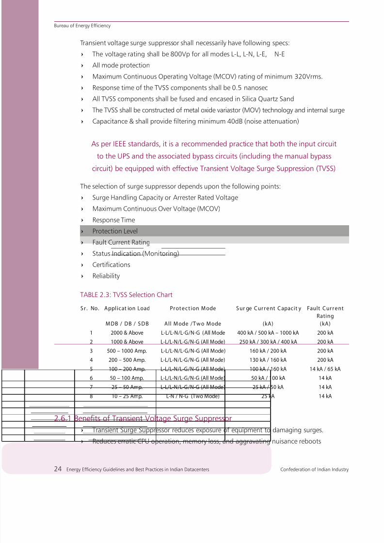
Transient voltage surge suppressor shall necessarily have following specs:
The voltage rating shall be 800Vp for all modes L-L, L-N, L-E, N-E=
All mode protection=
Maximum Continuous Operating Voltage (MCOV) rating of minimum 320Vrms.=
Response time of the TVSS components shall be 0.5 nanosec=
All TVSS components shall be fused and encased in Silica Quartz Sand=
The TVSS shall be constructed of metal oxide variastor (MOV) technology and internal surge=
Capacitance & shall provide filtering minimum 40dB (noise attenuation)=
The selection of surge suppressor depends upon the following points:
Surge Handling Capacity or Arrester Rated Voltage=
Maximum Continuous Over Voltage (MCOV)=
Response Time=
Protection Level=
Fault Current Rating=
Status Indication (Monitoring)=
Certifications=
Reliability=
TABLE 2.3: TVSS Selection Chart
S r . No. Applicat ion Load Pr ot e ct ion M ode S ur ge C ur r e nt C apacit y Fault Cur r e nt
Rating
M DB / DB / S D B All M ode / T wo M ode (kA) ( kA)
1 2000 & Above L-L/L-N/L-G/N-G (All Mode 400 kA / 500 kA – 1000 kA 200 kA
2 1000 & Above L-L/L-N/L-G/N-G (All Mode) 250 kA / 300 kA / 400 kA 200 kA
3 500 – 1000 Amp. L-L/L-N/L-G/N-G (All Mode) 160 kA / 200 kA 200 kA
4 200 – 500 Amp. L-L/L-N/L-G/N-G (All Mode) 130 kA / 160 kA 200 kA
5 100 – 200 Amp. L-L/L-N/L-G/N-G (All Mode) 100 kA / 160 kA 14 kA / 65 kA
6 50 – 100 Amp. L-L/L-N/L-G/N-G (All Mode) 50 kA / 100 kA 14 kA7 25 – 50 Amp. L-L/L-N/L-G/N-G (All Mode) 25 kA / 50 kA 14 kA
8 10 – 25 Amp. L-N / N-G (Two Mode) 25 kA 14 kA
2.6.1 Benefits of Transient Voltage Surge Suppressor
Transient Surge Suppressor reduces exposure of equipment to damaging surges.=
Reduces erratic CPU operation, memory loss, and aggravating nuisance reboots=
As per IEEE standards, it is a recommended practice that both the input circuit
to the UPS and the associated bypass circuits (including the manual bypass
circuit) be equipped with effective Transient Voltage Surge Suppression (TVSS)

8/12/2019 CII & BEE Data Center Book
http://slidepdf.com/reader/full/cii-bee-data-center-book 45/250
Confederation of Indian Industry Energy Efficiency Guidelines and Best Practices in Indian Datacenters 25
Bureau of Energy Efficiency
Continuous Protection. No labor or time involved=
Increased survivability. Long life expectancy=
Reacts to transients before they reach load equipment. Lower let-through voltage=
Consistent performance and durability. Extends component life and prevents adverse=
effects from environmental factors
2.7.0 Distribution board
The Primary function of the switchgear in a mission critical power system is electrical power
distribution throughout the facility. However, switchgear also provides an important function
of protecting the system from electrical faults upstream and down stream of the UPS.
2.7.1 Key functions of Switchgear
Provide electrical power distribution for the critical systems=
Utilization of power bus and circuit breakers through multiple paths=
Provides isolation and protection=
Circuit breaker and alternative power paths allow for continuous operation=
Protects the systems from electrical faults=
Provide physically and electrically isolatable components and alternative / bypass power=
paths for safe and reliable maintenance procedures
Provide voltage and current sending points for performance monitoring equipments=
2.8.0 Uninterrupted Power Supply (UPS) System
Figure 2.8: UPS as a load and Power Sources
The Uninterruptible Power Supply is the heart of any critical power infrastructure. The UPS
provides the primary protection from harmful power disturbances as well as gives a linkage to
stored energy source or alternative power sources during times of outage. Figure 2.8 shows
the basic function of a UPS. AC power, poor in quality, flows from the primary source i.e the

8/12/2019 CII & BEE Data Center Book
http://slidepdf.com/reader/full/cii-bee-data-center-book 46/250
Bureau of Energy Efficiency
26 Energy Efficiency Guidelines and Best Practices in Indian Datacenters Confederation of Indian Industry
commercial mains supply. The UPS, acting as both a load and a source, transforms this poor-
quality power to high-quality power, which can then be safely applied to critical loads.
Commercial Power containing spikes, sags, and outages would cause data loss and severe
damage to IT infrastructure in a Datacenter. An Uninterruptible Power Supply (UPS) is used
to protect Datacenters from an unexpected power disruption which would cause data loss
resulting in disastrous consequences for the company
Figure 2.9: Typical Schematic diagram of Uninterruptible Power Supply
The UPS is one of the most critical pieces of equipment in a Datacenter. Typically, online UPS
systems are used in Datacenters. These systems are ideal for environments where electrical
isolation is necessary or the equipment in use is highly sensitive to power fluctuations.
Traditionally, the selection of UPS systems has focused on system reliability without giving
much thought to the system efficiency. However, with the increase in energy costs and as
a consequence of the energy shortage situation, the efficiency of the UPS system has now
become a major consideration, while reliability still remains as the topmost criteria.
In order to have redundancy level in a Datacenter, the number of UPS systems is increased. This
The UPS has a battery back-up system which provides emergency power until
an auxiliary power supply is turned on, or the utility power is restored, or the
equipment is shut down safely
The number of UPS systems to be used for a particular Datacenter depends
on the Tier level of the Datacenter and also on the significance of the process
UPS system efficiency, as for any other electrical equipment,
depends on the loading

8/12/2019 CII & BEE Data Center Book
http://slidepdf.com/reader/full/cii-bee-data-center-book 47/250
Confederation of Indian Industry Energy Efficiency Guidelines and Best Practices in Indian Datacenters 27
Bureau of Energy Efficiency
eventually leads to decrease in the loading of UPS systems.
The Loading vs. Efficiency curve is shown in the Figure 2.10. The curve shows that, in most
cases, the operating efficiency of the UPS system reduces due to lower load on the UPS.
Figure 2.10: Loading versus. Efficiency Curve for a UPS
The change in efficiency with varying load has another important effect on the interpretation
of operating efficiency. Consider the case of the two Datacenters being compared in Figure
2.11.
Figure 2.11: Comparison of the efficiency curves vs IT load for two different Datacenters
Datacenter A appears to have the better design efficiency and it may seem reasonable to
assume that it is a “Greener” Datacenter of fundamentally superior design. However, consider
the detailed view of these two Datacenters as shown in Figure 2.11, the design efficiency of
Datacenter A is higher than that of Datacenter B. Nevertheless, the operating efficiency of
Datacenter A is lower than that of Datacenter B if Datacenter A faces only 14% loading and
Datacenter B faces 58% loading. The Low operating efficiency is due to a low percentage load

8/12/2019 CII & BEE Data Center Book
http://slidepdf.com/reader/full/cii-bee-data-center-book 48/250
Bureau of Energy Efficiency
28 Energy Efficiency Guidelines and Best Practices in Indian Datacenters Confederation of Indian Industry
on the IT equipment and therefore on the overall infrastructure.
Low operating efficiency is due to the following reasons
Varying load requirements with respect to time=
Over-sizing of equipment by design=
Installation of multiple equipment to facilitate higher redundancy level=
Various techniques are available to optimize the loading of the UPS system and to optimally
share the load on all the UPS systems. Modularity is one such method to improve the efficiency
of the UPS system. Modularity allows users to size the UPS system as closely with the load as
practical (in other words, it allows the UPS to operate as far right on the curve as possible).
UPS technologies continue to evolve towards greater electrical efficiency and the newer
technologies available will yield greater benefits.
2.8.1 UPS Topologies
There are three basic types of UPS System, depending on which further configurations can be made
Offline System / Stand by System=
Line Interactive System=
On-line System / Double Conversion System=
Offline UPS: (Passive standby)
This system energizes the load directly from the utility mains. It contains a charger and
an Off- Line Inverter. The Inverter is switched ON upon mains outage to supply the load
as shown in figure 2.12.
Figure 2.12: Block Diagram of Off Line UPS System
Line interactive :
During normal operation Mains Supply is extended to load. “Converter / Inverter Section”
acts as a “Charger” which maintains battery in charged condition. During a power
failure the “Converter / Inverter Section” acts as “Inverter” which utilizes energy stored

8/12/2019 CII & BEE Data Center Book
http://slidepdf.com/reader/full/cii-bee-data-center-book 49/250
Confederation of Indian Industry Energy Efficiency Guidelines and Best Practices in Indian Datacenters 29
Bureau of Energy Efficiency
in battery to feed load as shown in figure 2.13.
Figure 2.13: Line interactive UPS Configuration
Online double conversion:
(True on line): A double conversion system, which energizes the load continuously from
the inverter. The inverter is fed from mains via a rectifier in normal operation, or from
batteries upon mains outage.
Figure 2.14: On-Line Double Conversion UPS Configuration
Out of all the above UPS topologies, the Online Double conversion transfer topology is the
only one that protects against the full range of power disturbances and is recommended for
applications that are currently mission-critical or expected to become mission-critical, whichincludes virtually all Datacenters. Selecting an online double-conversion UPS ensures that
availability requirements will not outgrow UPS topology.
2.8.2 Selection criteria
Compliance to established international guidelines, codes and standards : IEC 62040, IEC 146,
IEEE 1100, other IEEE/IEC/EN/ANSI Codes and guidelines for UPS Modules and Batteries, DIN

8/12/2019 CII & BEE Data Center Book
http://slidepdf.com/reader/full/cii-bee-data-center-book 50/250
Bureau of Energy Efficiency
30 Energy Efficiency Guidelines and Best Practices in Indian Datacenters Confederation of Indian Industry
41772 ( Rectifier adequacy for Battery Charging), IEC62040-3 for Performance Measurement
Criteria, UL Listing for TVSS and ATS.
Optimal Redundancy and Minimised Common Point of Failures in order to meet User’s•
Tier Level, criticality and Availability needs
Optimal Galvanic Isolation of Supply Phases and Neutrals•
Design adequacy towards Safety of human and machine•
Optimal & Adequate Sizing of all components•
Compatibility with source and Load•
Energy conservation considerations such as : Energy Optimisers, Adequate filtration for KW-
KVA Parity, Intelligent Battery Management, AC-AC Efficiency, heat loads and need of air
conditioning,
The Watch word here is doing the selections "Just optimally"... one should not either underdoit (Which may lead to compromised design, nagging failures, reliability and safety question
marks) or overdo it (Which will lead to higher consumption of Energy).
2.8.3 UPS configuration
Figure 2.15: UPS Configurations
2.8.4 High availability power system
The computing industry talks of availability in terms of « Nines ». This refers to the percentage
of time in a year that their system is available, on-line, and capable of doing productive
work. A system with four “Nines” is 99.99% available, meaning that downtime is less than
53 minutes per year. Five “Nines” (99.999% available) equates to less that 5.3 minutes of downtime
CONFIGURATIONS
MODULE MODULE
SPLIT BYPASS BYPASS
PARALLELREDUNDANT
BATTERY BATTERY BATTERY BATTERY
PARALLEL ADDON

8/12/2019 CII & BEE Data Center Book
http://slidepdf.com/reader/full/cii-bee-data-center-book 51/250
Confederation of Indian Industry Energy Efficiency Guidelines and Best Practices in Indian Datacenters 31
Bureau of Energy Efficiency
per year. Six “Nines” (99.9999% available) equates to just 32 seconds of downtimes per year.
Improving Availability means improving MTBF and/or reducing MTTR. This will not yield the
significant improvement truly critical operations need to go beyond 99.999%.
2.8.5 Determination of availability
Availability = MTBF / (MTBF +MTTR)
MTBF (Mean time before failure) =increased Reliability
MTTR (Mean Time between Repair) = Fast Recovery
MTBF (Mean Time between Failures)
The reliability of the Datacenter is inversely proportional to the time taken between failures.
– 37% chance of still working
Figure 2.16: Graphical Representation of MTBF
MTTR (Mean Time to Repair)
– 63% chance of having been repaired
Figure 2.17: Graphical Representation of MTTR
Calculation to improve availability by paralleling UPS system for Redundancy
For Paralleled Systems,
o MTBF = MTBF1 + MTBF 2 + ((MTBF1 x MTBF2)/ (MTTR)

8/12/2019 CII & BEE Data Center Book
http://slidepdf.com/reader/full/cii-bee-data-center-book 52/250
Bureau of Energy Efficiency
32 Energy Efficiency Guidelines and Best Practices in Indian Datacenters Confederation of Indian Industry
Figure 2.18 b: Schematic of a Flywheel based Static UPS
2.8.6 UPS efficiency
Today it is both possible and prudent to plan, measure, and improve Datacenter efficiency. In
addition to reducing electrical consumption, efficiency improvements can give users higher IT
power densities and the ability to install more IT equipment in a given installation.
2.8.7 Rotary and Battery-Less UPS system
Figure 2.18 a: Schematic of Rotary UPS system
There are two distinct variants of Battery-Less UPS. One which uses a Static UPS combined with
Flywheel plus Flywheel converter as shown in Figure 2.18 (a) below. Flywheel plus Converter
acts as alternative to the Batteries. In this case, during Utility Power supply outage the Kinetic
energy of Flywheel-rotation gives the backup / ride-through to the Inverter for a few seconds
till the Generator is energized and connected to the Rectifier. The second one as shown inFigure 2.18 (b) below which uses a Rotary Motor-Generator Set-up coupled with a Diesel /
Natural Gas Engine through a Clutch arrangement and a Flywheel plus AC-DC-AC Converter
(which is a Static Element). This is, therefore, also known as a Hybrid UPS since it actually
uses a combination of Rotary and Static Elements. Both the above variants leave option for
connection of Batteries also. While the Flywheel provides a ride-through of a few seconds upon
Utility failure, the Engine starts and connects through the Clutch meanwhile, maintaining the
rotational energy to the generator which in turn maintains the Power Supply to the Loads.
Flywheel

8/12/2019 CII & BEE Data Center Book
http://slidepdf.com/reader/full/cii-bee-data-center-book 53/250
Confederation of Indian Industry Energy Efficiency Guidelines and Best Practices in Indian Datacenters 33
Bureau of Energy Efficiency
Advantages and disadvantages of Batteryless / Rotary UPS systems
Advantages
Being Battery-Less, design restrictions associated with specific Batteries are overcome
Rotary / Hybrid System due to its low impedance ….. have superior fault clearing capability
Capable of supplying high-inrush loads such as transformers /motors/inductive loads
Rotary / Hybrid system when operating from Utility Power Supply has higher efficiency compared
to Static Unit
Rotary System, if operated directly through the Motor-Generator Set, has much lower current
harmonic distortion
It is particularly energy saving for applications where Utility Supply Interruption is less than about
750 outages per year and each interruption does not exceed 3-4 second
Disadvantages
Rotary/Hybrid UPS using Diesel Engine are associated with Engine malfunctioning and
failure facing high block-loads. Engine needs early replacement
Rotary/Hybrid UPS using Diesel Engine are associated with nagging Clutch failure and
frequent replacements when used in Indian conditions having 2 or more outages per day.
The clutch is designed for finite life of about 750 operations per year
Flywheel based Static UPS heavily depends on fast starting-up and synchronizing of the
backup Generator within few seconds. If power demand requires multiple number of
backup generators to be synchronized, this system interrupt supply to load/equipment if
generator output fails to come up in time
In flywheel based Static UPS of Higher KVA Ratings, trying to achieve ride-through/backup
of >9 secs requires paralleling and synchronous running of 4-5 Flywheels. Speed variation
between individual Flywheels may cripple system reliability

8/12/2019 CII & BEE Data Center Book
http://slidepdf.com/reader/full/cii-bee-data-center-book 54/250
Bureau of Energy Efficiency
34 Energy Efficiency Guidelines and Best Practices in Indian Datacenters Confederation of Indian Industry
2.9 Power Distribution Units
The distribution of power to the IT load is done through power distribution units (PDU). The
schematic representation of the power distribution from the UPS to the IT load through the
PDU is shown in Figure 2.19.
Figure 2.19: Diagram of Power Distribution from the UPS to the IT load through the PDU
To maintain high levels of redundancy, two or more PDUs are provided to distribute power
to each of the server racks. In the case of a failure of any one of the PDUs, the distribution of
power would be taken by the other PDUs present in the loop and thus uninterruptible power
supply to the server racks.
The traditional PDU architecture, which had severely shortened the capacity expansion ability
of a Datacenter, have been replaced with modular power distribution units, which has certain
inherent properties which makes it superior to the conventional PDUs.
2.9.1 Challenges faced with traditional PDUs
Traditional PDUs require many receptacles as Datacenters typically have a large number of=
plug-in devices with separate power cords
The modern high density IT servers have different power requirements and/or receptacle=
requirements at the rack location
The changing power requirements would require the addition of new power circuits,=
which have to be added to the live Datacenter without disturbing existing IT loads
Obstruction of air-flow to the IT equipment by the power cords in under-floor air=
plenum
The above challenges can be addressed using modular power distribution design.
2.9.2 Modular Power Distribution Unit (PDU)
The power distribution unit includes a frame, and one or more user-replaceable power modules
that fit into slots in the frame. Each power module has one or more plug receptacles to provide
power to the equipment connected. The power modules are available in a variety of receptacle
types, receptacle numbers, and power rating configurations to accommodate the equipment
in a particular environment as required.

8/12/2019 CII & BEE Data Center Book
http://slidepdf.com/reader/full/cii-bee-data-center-book 55/250

8/12/2019 CII & BEE Data Center Book
http://slidepdf.com/reader/full/cii-bee-data-center-book 56/250

8/12/2019 CII & BEE Data Center Book
http://slidepdf.com/reader/full/cii-bee-data-center-book 57/250
Confederation of Indian Industry Energy Efficiency Guidelines and Best Practices in Indian Datacenters 37
Bureau of Energy Efficiency
Benefits of Advanced Power Strips
Protection against Inadvertent overloading=
Can monitor & control high Electrical load densities=
Load Monitoring and Control=
High Reliability=
True Power Monitoring=
2.12 Energy saving opportunities in Electrical systems
This section briefly discusses various energy saving opportunities in Datacenter electrical
systems. The following energy saving techniques are supported by the case studies/write-ups
detailed later in the section.
Energy saving measure 1: Optimizing the loading on the UPS and PDU systems
The Datacenter facility managers maintain certain redundancy levels to sustain site operations
as required. However, some Datacenters are operated with more redundant systems than
recommended.
Increase in redundancy compromises the operating efficiency of the system
The operation of the modules can be controlled so that the units operate at a higher load factor.
This would result in better operational efficiency. The details of the project demonstrating this
concept are discussed in Case Study No. 2.
The efficiency of the UPS system varies with loading. Typically, an UPS system has maximum efficiency
at 75-80% loading. When loading is less than 40-45%, the efficiency reduces drastically.
It is recommended that the UPS loading be maintained at more than 40%
Energy saving measure 2: Using energy optimizer
Enabling dynamic source adaptability to load requirement would result in optimal operating
range, and reduce energy costs, compared to using a static source installation model.
An Energy Optimizer is a device which senses the load demand continuously
and controls the operation of the number of UPSs at any point of time, and also
maintains optimum loading on all UPS
Redundancy levels and sequencing operation are some of the features which can be set based
on user requirement. The schematic representation of an Energy optimizer connection to the
UPS system is shown in Figure 2.23.

8/12/2019 CII & BEE Data Center Book
http://slidepdf.com/reader/full/cii-bee-data-center-book 58/250
Bureau of Energy Efficiency
38 Energy Efficiency Guidelines and Best Practices in Indian Datacenters Confederation of Indian Industry
Figure 2.23: Energy Optimizer connected to UPS system
Energy Optimizer senses the load demand continuously and intervenes to maintain required
number of UPS systems operating at any given point of time. Redundancy levels and sequencing
operation can be set in the optimizer.
UPS system no load loss were significant compared to the actual load loss on each UPS.
For example, Night and Weekend/off day loads may be quite different from regular daytime
load. All the factors mentioned above asserts a simple fact that UPS systems are being loaded
way below its optimal bandwidth of performance.
It is a well-known fact that the best operating efficiency of the system of any electrical
equipment lies at 50-80% load. Though, all efforts are being made to have Efficiency curve
flatter between 25% to 100% load, Efficiency at lower than 40% load is disproportionately
lesser compared to optimal performance.
Intelligent Energy optimizer functionality in UPS systems ensure UPS systems are dynamically
switching ON/OFF as per load pattern and Maintaining load on each UPS above 50%. As this
load range gives highest efficiency, the customers will reap in benefit from reduced energy
bills, enhancing the profitability.
Energy saving measure 3: Use of energy efficient transformers
The transformer is at the heart of an electrical distribution system. The power to IT systems
is distributed through transformers. The efficiency of the transformer plays a major role in
efficient power distribution.
The latest models of transformers offer better efficiency levels than conventional transformers,
which have comparatively high inherent losses associated with them Further, judiciously
selecting optimal size of the transformer will ensure that transformer faces optimal load for
which its efficiency is higher.
The inherent loss associated with transformers depends upon the type of core used in the
transformers.

8/12/2019 CII & BEE Data Center Book
http://slidepdf.com/reader/full/cii-bee-data-center-book 59/250
Confederation of Indian Industry Energy Efficiency Guidelines and Best Practices in Indian Datacenters 39
Bureau of Energy Efficiency
The magnetic core of these transformers is built with superior material which helps to conserve
energy right from the time of installation.
Energy saving measure 4: Harmonic mitigation
Energy Efficiency through lowering of KVA intake can be effectively achieved through mitigation
of harmonics by deploying a host of Parallel-connected harmonic filters. There are various kindof Harmonics filters available viz the Passive uncompensated filter, Passive compensated Filter
and Active-Dynamic Active Filters out of which a combination of Passive and Active Filters are
found to be most beneficial. Ideally Active filters, selected for a combination of loads rather
than individual loads, are found to be techno-economically beneficial since harmonic currents
of some individual loads cancel each other. The Type, rating and location of the Filters to be
cautiously selected and sized optimally based on extent of correction needed. The Point at
which correction is needed (Point of common Coupling as per per IEEE 519) and the efficiency
of the Filter circuit. It may be advisable to prefer those means of Harmonic reduction which
are associated with lowest possible increase in KW consumption and heat load and do not
increase the number of components in series electrical path.
Nonlinear loads such as UPS, SMPS, and rectifiers, which are predominantly used in Datacenters,
lead to harmonic distortion.
Excessive harmonic currents can overload wiring and transformers, leading to additional
losses. Therefore, it is necessary to maintain the harmonics levels in the electrical system as
recommended in the IEEE 519 standards.
The permissible limit for voltage harmonics varies with the voltage level of operation. Table 2.4
shows the permissible voltage harmonic limit in percentage for various distribution voltage levels.
Table 2.4: Voltage harmonic levels for various distribution voltage levels
Supply System
Voltage (kV)
Total Harmonic Voltage
Distortion VT (%)
Individual Harmonic
Voltage Distortion (%)
0.415 5 4 2
6.6 and 11 4 3 1.75
33 and 66 3 2 1
132 1.5 1 0.5
The permissible limit for current harmonics as per IEEE standards is specified in table 2.5.
Current distortion limits for general distribution systems end user limits (From 240 V to 69 kV)

8/12/2019 CII & BEE Data Center Book
http://slidepdf.com/reader/full/cii-bee-data-center-book 60/250

8/12/2019 CII & BEE Data Center Book
http://slidepdf.com/reader/full/cii-bee-data-center-book 61/250
Confederation of Indian Industry Energy Efficiency Guidelines and Best Practices in Indian Datacenters 41
Bureau of Energy Efficiency
Figure 2.24: Monitoring Activities
Energy Saving Measure 6: Use of Energy Efficient power supplies
Voltage is stepped down in the incoming transformer and the conversion of power takes place
in the UPS switching circuit.
Power conversions result in certain losses in the equipment. The latest PDUs and UPS system using
low-loss switching devices minimize the loss in the system and improve system efficiency.
Energy Saving Measure 7: Regular Maintenance and Testing of Electrical Systems
'Maintenance' refers not only to the repair and maintenance of equipment, but also operating
the equipment in a safe, reliable and efficient manner.
Maintenance personnel have to keep track of all the above aspects to ensure operational
excellence in electrical systems.
An Energy Optimizer is a device which senses the load demand continuously
and controls the operation of the number of UPSs at any point of time, and also
maintains optimum loading on all UPS
Energy saving measure 8: Regular maintenance of capacitors in the UPS
DC capacitors used in the UPS system wear out after a certain number of working hours. If a
worn out capacitor is allowed to operate in the UPS system, it would result in the inverter failing
to operate under load and would cause an increase in the ripple current in the batteries.
This results in inefficient operation of the equipment. Therefore, it is necessary to monitor the
capacitors at regular intervals to ensure that they are in proper working condition.
8/12/2019 CII & BEE Data Center Book
http://slidepdf.com/reader/full/cii-bee-data-center-book 62/250
Bureau of Energy Efficiency
42 Energy Efficiency Guidelines and Best Practices in Indian Datacenters Confederation of Indian Industry
Energy saving measure 9: Energy efficient motors
Energy Efficient Motors have design improvements incorporated specifically to increase their
operating efficiency over standard motors. Energy Efficient Motors are designed with low
operating losses.
The efficiency of Energy Efficient motors available in the market ranges from 80 to 95%.Therefore opting for energy efficient motors at the design stage will lead to improved energy
efficiency.
Energy Saving Measure 10 : Energy Efficient Cabling / Busbars
Selecting Cables / Bus-bars with proven lesser impedance-drops per metre of its length helpsa lot in reducing transmission losses and contributes appreciably in Energy Efficient System.Further, in occasions it may be a good idea to select Cables “One-Size-Up” which means justby going for higher sized cable one may ensure lesser drop and therefore, higher distribution
efficiency.

8/12/2019 CII & BEE Data Center Book
http://slidepdf.com/reader/full/cii-bee-data-center-book 63/250
Confederation of Indian Industry Energy Efficiency Guidelines and Best Practices in Indian Datacenters 43
Bureau of Energy Efficiency
Case Study 1
POWER QUALITY IMPROVEMENT IN A DATACENTER BYINSTALLING HARMONIC FILTERS
Background
The Power factor is one of the major parameters that influence the performance of an electrical system.
The power factor is influenced by both the reactive power requirement of the load and the harmonics
present in the system.
Harmonics are generated due to the presence of non-linear switching loads such as UPS, display units,
PAC, and HVAC controls in the circuit. Harmonics, when exceeding a certain limit in a system cause
undesirable effects. The undesirable effects caused by the presence of harmonics are malfunctioning of
protective relay equipments, de-rating of equipment capacity, premature failure due to increased stress
on the electrical system, etc.
The presence of higher harmonics affects the power factor negatively and increases the KVA
demand requirement for any KW load
IEEE 519 standards specify the limit for both voltage and current harmonics. The current harmonics
limit depends on the ratio of Short Circuit Current (SCC) at PCC to average Load Current of maximum
demand over 1 year. Thus the current harmonic limit is a function of system design.
Also the voltage harmonics depends on the bus voltage. Typically, the voltage harmonic limit at 415V
bus is 5%.
Project details
The company is an Indian telecom giant with an exclusive Datacenter catering to their internal needs.
The organization conducted an energy study to look into opportunity-related cost reduction through
better energy management.
The energy cost has two components, one based on the actual power consumption (kWh or Active
power) and the other based on the maximum demand registered (kVA or apparent power). The latter
is affected by the system power factor.
The measured system power factor was 0.88 lagging for the average load of 1030 kW. The harmonic
levels in the system were also measured with a power quality analyzer and the measurements were
analyzed.

8/12/2019 CII & BEE Data Center Book
http://slidepdf.com/reader/full/cii-bee-data-center-book 64/250
Bureau of Energy Efficiency
44 Energy Efficiency Guidelines and Best Practices in Indian Datacenters Confederation of Indian Industry
The project team inferred that the power factor was low and can be substantially improved. They also
inferred that harmonic levels in the system can be reduced. It was decided that solutions for improving
the power factor and mitigating the harmonics can be implemented by using a combination of APFC
(Automatic Power Factor Correction) system and an Active harmonics filter.
The organization procured and installed a 2 x 225 Amp Active Harmonic Filter along with a 225 kVAR
APFC system in the Main Incoming panel of the building housing the Datacenter.
This improved the power factor from 0.88 lagging upto 0.97 lagging, reducing the demand by 96 kVA.
Figure 2.25: Typical Connection of an Active Harmonic Filter
The harmonic filter design is site specific, and is based on the operating conditions. The filter
has to be selected based on the requirements specified in the detailed study
Benefits of the project
In spite of the server Load remaining the same (600 KW), there was a small increase in power consumption
to compensate for the losses in filters (19kW). There was a 96 KVA reduction in Demand, with the
demand reducing from 1198 KVA to 1102 KVA. The summary of the pre- and post- filter installation
audit is given in table 2.6.
Table 2.6: Data Summary of the Facility Audit: Pre- and Post-Filters Installation
KW KVA PFTotal with APFC capacitor banks Connected 1050 1198 0.88
After installing Active Filter 1069 1102 0.97

8/12/2019 CII & BEE Data Center Book
http://slidepdf.com/reader/full/cii-bee-data-center-book 65/250
Confederation of Indian Industry Energy Efficiency Guidelines and Best Practices in Indian Datacenters 45
Bureau of Energy Efficiency
Benefits of the project
Reduction in demand from 1198 kVA to 1102 kVA
Harmonics level controlled to be within desirable limits
Better operating power factor
Reduced electricity bill
The project involving installation of Harmonic filters is recommended for scenarios
where harmonic levels are higher than the IEEE 519 standard
The project involved minor modification/retrofitting of filters in electrical
infrastructure requiring external expertise. The project, being capital intensive, has
to be taken up as part of a business decision
Cost benefit analysis
Annual savings - Rs. 3.3 million
Investment - Rs. 4 million
Payback period - 15 months
Financial analysis
The implementation of active harmonics filters resulted in an annual savings achieved of Rs 3.3 million.
The investment made for this project was Rs 4 million. The pay back period is 15 months.

8/12/2019 CII & BEE Data Center Book
http://slidepdf.com/reader/full/cii-bee-data-center-book 66/250
Bureau of Energy Efficiency
46 Energy Efficiency Guidelines and Best Practices in Indian Datacenters Confederation of Indian Industry
Case Study 2
ENERGY EFFICIENCY IMPROVEMENT IN UPS SYSTEMS BYLOADING OPTIMIZATION
Background
A Datacenter is an environment in which uptime and availability is critical and needs to be maintained
at the maximum. The uptime of a Datacenter can be maintained by ensuring the availability of a
continuous power supply to its IT equipment.
Reliability in power supply is achieved through an Uninterruptible power supply (UPS) system. The UPS
is one of the major energy consumers in a Datacenter, as it is used to provide continuous power supply
to all IT equipments. Thus the continuous functioning of a UPS system is critical in a Datacenter.
The efficiency of the UPS system varies with loading. Typically, an UPS system has maximum efficiencyat 75-80% loading. At loading of less than 40-45%, the efficiency reduces drastically. Table 2.7 shows
the typical efficiency of the UPS system corresponding to loading of the UPS system. Figure 2.26 shows
the Loading vs Efficiency curve of an UPS system.
Table 2.7: EFFICIENCY DATA OF 200 KVA UPS SYSTEM
% Loading Efficiency
10% 80.00%
15% 84.00%
20% 87.00%
25% 89.16%
30% 91.00%
40% 91.95%
50% 92.80%
60% 93.00%
70% 93.40%
80% 93.46%
90% 93.15%100% 93.00%
Project details
The organization is a well known software development company with international clientele. The
organization maintains a Datacenter which caters to the needs of various clients abroad.
Figure 2.26: Loading (vs.) Efficiency curve of the UPS
E f f i c i e n c y i n %
Loading in %
10 20 30 40 50 60 70 80 90 100 110 120
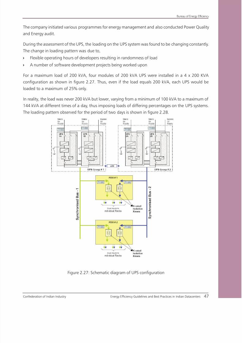
8/12/2019 CII & BEE Data Center Book
http://slidepdf.com/reader/full/cii-bee-data-center-book 67/250
Confederation of Indian Industry Energy Efficiency Guidelines and Best Practices in Indian Datacenters 47
Bureau of Energy Efficiency
The company initiated various programmes for energy management and also conducted Power Quality
and Energy audit.
During the assessment of the UPS, the loading on the UPS system was found to be changing constantly.
The change in loading pattern was due to,
Flexible operating hours of developers resulting in randomness of load=
A number of software development projects being worked upon=
For a maximum load of 200 kVA, four modules of 200 kVA UPS were installed in a 4 x 200 KVA
configuration as shown in figure 2.27. Thus, even if the load equals 200 kVA, each UPS would be
loaded to a maximum of 25% only.
In reality, the load was never 200 kVA but lower, varying from a minimum of 100 kVA to a maximum of
144 kVA at different times of a day, thus imposing loads of differing percentages on the UPS systems.
The loading pattern observed for the period of two days is shown in figure 2.28.
Figure 2.27: Schematic diagram of UPS configuration

8/12/2019 CII & BEE Data Center Book
http://slidepdf.com/reader/full/cii-bee-data-center-book 68/250
Bureau of Energy Efficiency
48 Energy Efficiency Guidelines and Best Practices in Indian Datacenters Confederation of Indian Industry
Figure 2.28: Loading pattern on UPS
The total load on the system varied from 100 kVA to 144 kVA which imposes 12.5% to 18% loading on
individual UPS. The project team observed that efficiency of UPS at these loading is around 83%, from
the efficiency chart supplied by the manuf acturer.
There was potential for improving the loading on the UPS system. An automation system was installed
to monitor the loading on individual UPSs, and to give commands on the basis of operation to all
UPS. The desired loading on UPS was maintained by designating the other UPSs to standby mode and
bringing them online whenever the load increased.
In the event of increase in load or malfunction in the On-load UPS, the other UPSs in the loop would
automatically take up the load. This mechanism increased the loading of the UPS system and thereby
increased circuit efficiency.
Care was taken to ensure that the circuit would be failsafe and very reliable in its design. Since the
circuit consisted of sensors and control logics only, its own losses were negligible.
Benefits of the project
For the same load variations, reliable operation of the UPS system was maintained. Intelligent control
logic regulated the operation of the inverter in the load bus of the UPS thus increasing the loading on
the UPS system.
The efficiency of the UPS system was improved by 6.7%. This resulted in a reduction of 20 kVA in
demand consumption.

8/12/2019 CII & BEE Data Center Book
http://slidepdf.com/reader/full/cii-bee-data-center-book 69/250
Confederation of Indian Industry Energy Efficiency Guidelines and Best Practices in Indian Datacenters 49
Bureau of Energy Efficiency
The improvement in efficiency due to load optimization is represented in Table 2.8 and Table 2.9.
Table 2.8: Summary Data Record & Analysis Pre-implementation of project
Before Planned Action
Load (kVA) UPS capacity (kVA) Loading on UPS (%) UPS Efficiency (%)
Loading Status - 1 127 800 15.88% 84.6%
Loading Status - 2 114 800 14.25% 83.3%
Loading Status - 3 100 800 12.50% 82.3%
Loading Status - 4 130 800 16.25% 85.1%
Loading Status - 5 144 800 18.00% 86.4%
Table 2.9: Summary Data Record & Analysis Post-implementation of project
After Planned ActionLoad (kVA) Total UPS capacity % loading UPS Efficiency
Loading Status - 1 127 400 31.75% 90.8%
Loading Status - 2 114 400 28.50% 90.3%
Loading Status - 3 100 400 25.00% 89.2%
Loading Status - 4 130 400 32.50% 91.1%
Loading Status - 5 144 400 36.00% 91.4%
The project on loading optimization of UPS systems would find replication in
scenarios when the loading of individual UPS in a bank of UPS systems is low
The project involves minor modification/retrofitting of power distribution infrastructure
requiring external expertise. The project, being capital intensive, has to be taken up
as part of a business decision

8/12/2019 CII & BEE Data Center Book
http://slidepdf.com/reader/full/cii-bee-data-center-book 70/250
Bureau of Energy Efficiency
50 Energy Efficiency Guidelines and Best Practices in Indian Datacenters Confederation of Indian Industry
Case Study 3
ENERGY EFFICIENCY IMPROVEMENT IN LIGHTING SYSTEM BYREPLACING FLUORESCENT LAMPS WITH LIGHT EMITTING DIODE
(LED) LAMPS
The project demonstrates the benefits of using Light Emitting Diode (LED) lamps instead of conventional
Compact Fluorescent Lamps (CFL) in achieving savings in electrical energy consumption.
Background
A light-emitting diode is an electronic light source. LEDs present many advantages over traditional
light sources such as lower energy consumption, longer life, improved robustness, smaller size and
faster switching. However, they are relatively expensive and require more precise current and heat
management as compared to traditional light sources.
One of the key advantages of LED-based lighting is its high
efficacy, as measured by its light output per unit power input
(Lumens/watt).
LEDs are available in different performance classes such as
standard; mid and high power packages, in various brightness
levels and package sizes and in a range of colors including all
shades of white, RGB, and colors-on-demand.
The comparison between LED and Fluorescent lamps are given in
Table 2.10.
Table 2.10 : Comparison of LED and Fluorescent lamps
Parameter Fluorescent Lamps LED Lamps
Efficacy 60-65 lm/W 105-120 lm/W
Lifetime 10000 to 15000 hrs 35000 to 50000 hrs
Mechanical strength Fragile Robust
Environmental aspect Contains mercury Less mercury content
Initial cost Medium High
Total ownership cost High Low
Voltage sensitivity Medium High
Temperature sensitivity Medium High
Figure 2.29: LED lamp

8/12/2019 CII & BEE Data Center Book
http://slidepdf.com/reader/full/cii-bee-data-center-book 71/250
Confederation of Indian Industry Energy Efficiency Guidelines and Best Practices in Indian Datacenters 51
Bureau of Energy Efficiency
Project details
The company carried out a lighting study throughout the facility. The lighting energy and LUX levels
were recorded and analyzed. It was noticed that a considerable share in overall operating cost could be
attributed to lighting.
The company decided to replace all compact fluorescent lamps with latest energy efficient LED lamps.
Retrofitting of lamps was possible due to the fact that no extra or special wiring is required for LED
lamps. The LED lamps were installed in utility rooms, and laboratories. They also replaced the existing
emergency lights in the Datacenter.
Also, the company segregated the lighting systems, based on the illumination requirement and occupancy
time. Lighting controls such as movement sensors were adopted for areas with intermittent occupancy.
Benefits of the project
Conventional CFLs were replaced with Energy efficient LED Lamps. The implementation was financially
rewarding for the organization. The project also had a positive environmental impact as LED lamps
contain no mercury.
The annual savings achieved was Rs 0.54 million. The investment made for this project was Rs 1 million
which is paid back in 22 months.
The project involves minor modification/retrofitting in lighting infrastructure requiring
external expertise. The project, being capital intensive, has to be taken up as part of a
business decision
Cost benefits analysis
Annual savings - Rs 0.54 million
Investment - Rs. 1 million
Pay Back - 22 months
Benefits of the project
Reduction in lighting power consumption by 73%, reducing total ownership cost (TOC)
No mercury content in LED lighting, thus addressing environmental concerns anddisposal issues
Increase in lifetime upto 3 times
The project was feasible and had an attractive pay back period due to high energy costs

8/12/2019 CII & BEE Data Center Book
http://slidepdf.com/reader/full/cii-bee-data-center-book 72/250
8/12/2019 CII & BEE Data Center Book
http://slidepdf.com/reader/full/cii-bee-data-center-book 73/250

8/12/2019 CII & BEE Data Center Book
http://slidepdf.com/reader/full/cii-bee-data-center-book 74/250

8/12/2019 CII & BEE Data Center Book
http://slidepdf.com/reader/full/cii-bee-data-center-book 75/250
SUMMARY NOTE ON
'DATA CENTRE COOLING SYSTEM'
Whereas the physical world is shrinking in terms of connectivity, however, the virtual worldis expanding its presence into our lives. With growing dependence of human society on the
Information Technology and miniaturization of electronics, increasing amount of information
is getting packed into the Data Centres in the same floor space. These Data centre are today
regarded as power guzzlers and with emergence of India as hotbed for IT industry, the size,
complexity as well as power requirement of Data Centre’s too has grown exponentially. Since
higher power demand results in increased internal heat rejection, thus its removal is a key
requirement. The operating temperatures and relative humidity levels within Data Centre also
needs to be closely controlled to ensure reliability in performance. In a typical Indian Data
Centre, HVAC systems consume nearly 35-40% of the total power demand, which presents an
opportunity for significant energy savings.
Lack of infrastructure and power scarcity has propelled Indian Owners to innovate on energy
conservation methods that are unique to our country. Add to it the wide ranges of ambient
conditions within the country and exposure to International practices that combined present a
huge potential to save on operation cost. The intent of this exercise is to present to readers a
compilation of all possible strategies as a handy tool which can be explored during construction
stage.
This exercise of developing Guidelines & Best Practice for Energy Efficiency in Indian Data Centre
by CII under the guidance of BEE is a unique initiative which brought all the players like Planners,Consultants, Users, Suppliers and Manufacturers on a common platform to share their ideas.
The chapter on 'Data Centre Cooling System' has come out with a set of few focused stress
points like use of economizer, intelligent controllers, EC fans, Aisle containment, redefining of
the operating specifications etc and should be a good reference material.
I am thankful to all members of this core Group for their contribution towards the successful
completion of section on Air-conditioning and express my sincere thanks to Dr Ajay Mathur,
Mr Sanjay Seth & Mr S Raghupathy for their guidance and Suprotim Ganguly for technical
contribution through out this project. Ashish Rakheja
Ashish RakhejaChairman, Core Group on ' Cooling System' &
Chief Operating Officer, Spectral Services Consultants Pvt.Ltd.

8/12/2019 CII & BEE Data Center Book
http://slidepdf.com/reader/full/cii-bee-data-center-book 76/250
LIST OF MEMBERS ON COOLING SYSTEM (CORE GROUP-2)
SI.NO Name Organization
1 Mr Ashish Raheja Spectral Services Consultants Pvt Ltd.
2 Mr Anil Dev Clivet TF Airsystems (P) Ltd
3 Mr Dhiman Ghosh Emerson Network Power (India) pvt Ltd
4 Mr Debashish Chakraborty APC-MGE
5 Mr. S. Gagneja Uniflair india pvt ltd
6 Mr Kiran Desai Wipro Technologies
7 Mr Kiran kumar Ctrl S Datacenters Ltd.
8 Mr Madhav Kamath USAID ECO-III Project, IRG
9 Mr Muralidharan Iyengar Blue star Ltd.
10 Mr Sanjeev Gupta IBM India Pvt. Ltd.
11 Mr Saurabh Agarwal Cadence Design Systems (I) Pvt Ltd.
12 Mr Salender Tomer Hewlett Packard India Sales Pvt. Ltd.
13 Mr Sital Bachhav STULZ-CHSPL (INDIA) PVT.LTD
14 Mr Sreekumar Kollara SCHNABEL dc consultants India
15 Mr Sushanta Ghosh Emerson Network Power (India) pvt Ltd
16 Mr Sudeep Palanna Texas Instruments (India) pvt Ltd
17 Mr Vijay Venugopal Cisco Systems (India) Pvt. Ltd.

8/12/2019 CII & BEE Data Center Book
http://slidepdf.com/reader/full/cii-bee-data-center-book 77/250
Confederation of Indian Industry Energy Efficiency Guidelines and Best Practices in Indian Datacenters 57
Bureau of Energy Efficiency
3.1 Introduction
The market keeps evaluating latest technologies such as Virtualization & Consolidation of
Datacenter so that the IT Infrastructure can be used with higher capacity utilization with better
ROI. The development of high density equipment for performance improvement has resulted
in concentrated generation of heat, posing a challenge to Data Center cooling systems.
The continuous operation of IT equipment and power delivery systems generate a significant
amount of heat that must be removed from the Datacenter for the equipment to operate
properly.
In a typical Datacenter, cooling system consumes 35 - 40% of the total power consumption, which
also presents an opportunity for significant energy saving.
The operating temperature and humidity level in a Datacenter has to be maintained at
recommended levels to ensure the performance of all the IT equipment. Therefore reliable
functioning of the cooling system is extremely important.
3.2 Cooling process in a Datacenter
The cooling process in a Datacenter is a closed loop system, ie, the cold air supplied from the
CRAC flows through the IT equipment and the hot air is re-circulated to the CRAC unit for
removal of heat.
Each server rack draws in cold air through the front of the rack and which gets heated as it
circulates inside the servers and exits the rack from the rear side. Cold air is supplied to the
server rack by the following two ways.
Conventional method - Room cooling technique
Contemporary method - Hot aisle/Cold aisle containment technique
In the conventional room cooling technique, the temperature distribution in the room is
determined by the inlet and outlet temperatures of different racks. The inlet temperature of
a rack depends on the cold air supplied from the CRAC. The outlet temperature of a rack
therefore depends on the inlet air temperature and the power consumption of that rack.
The mixing of cold and hot air results in an increased distribution supply temperature and
reduced return temperature to the crac which results in increase of load on the CRAC units.
Effective heat removal from IT equipment is one of the most essential processes
in the optimum operation of Datacenter

8/12/2019 CII & BEE Data Center Book
http://slidepdf.com/reader/full/cii-bee-data-center-book 78/250
Bureau of Energy Efficiency
58 Energy Efficiency Guidelines and Best Practices in Indian Datacenters Confederation of Indian Industry
Now a days, several Data Centers are coming up with Hot aisle / Cold aisle containment
technique.
Figure-3.1 shows the typical layout this technique. The racks are arranged such that the hot
and cold sides are segregated to form an array of alternative Cold and Hot aisles.
Figure 3.1: The raised floor of a Datacenter with the Hot aisle /Cold aisle setup
Air is being supplied through perforated floor tiles in the cold aisle. The inlets of each rack face
the cold aisle and draws cold air coming out of the perforated floor tiles. This arrangement
allows the hot air exiting from the rear side of the racks to return to the CRAC, thus minimizing
the recirculation of hot exhaust air from the rack back towards the inlets of other racks. Hence,
it becomes very important to ensure that significant amount of Cold Air (Equivalent or more
than the amount required by rack load) should be available in the front of the racks. As higherperforation levels of the rack door (up to 83%) enable better airflow, it is recommended to
have as high perforation levels as possible. Designs of racks are available upto 83% perforation
levels.
Servers with critical duties will shutdown or fail when the inlet temperature and humidity
levels rise above the specified standards, which typically are 20-25OC and 40-55%RH. The
temperature of high density equipment in Datacenters can rise up to 40OC in 3 minutes in the
absence of CRAC units. Therefore, failure-free operation of CRAC units is absolutely necessary
to ensure reliable operation of the servers.
The cooling system has various components such as
Chiller units=
Chilled water pumping system=
Precision air conditioner unit=
Air distribution system.=
Both the chilled water system and direct expansion type of cooling are used in Datacenters.

8/12/2019 CII & BEE Data Center Book
http://slidepdf.com/reader/full/cii-bee-data-center-book 79/250
Confederation of Indian Industry Energy Efficiency Guidelines and Best Practices in Indian Datacenters 59
Bureau of Energy Efficiency
3.3 Critical cooling configuration and its components
Precision Air Conditioner (PAC) units are essential in a Datacenter to maintain the equipment
within the manufacturers’ specified temperature/humidity range. PAC is a high precision
environment control system, specially designed to manage the cooling, heating & ventilation
requirements of mission critical applications. The precision air conditioner units could have
one of the configurations, which are detailed below:
3.3.1 Direct expansion air cooled unit
Direct expansion (DX) system is a compressor based refrigeration system equipped with
refrigerant as a cooling medium. The outdoor condenser unit used for heat rejection can be
air/water cooled. The indoor and outdoor units are connected by means of pipes. The general
schematic of the configuration is as shown below:
CRAC’s are one of the most common cooling systems installed in upcoming Datacenters. CRAC
uses the direct expansion of refrigerant gases to remove heat inside the Datacenter and reject
it to outdoor spaces. These systems typically has a relatively small (30 Tons sensible capacity)
compressor system and e vaporator coil installed in the datacenter space, and a condensing unit
installed outdoors to reject the energy from the room.
Figure 3.2: Typical Layout for direct expansion based precision cooling
A typical layout for precision cooling with direct expansion of refrigerant in evaporator is
shown in figure 3.2 Due to the low temperature of the evaporator coil, the moisture in the
air condenses and dehumidifies the air. A humidification system is provided to impart required
moisture to the air to maintain the humidity level within the specified range.
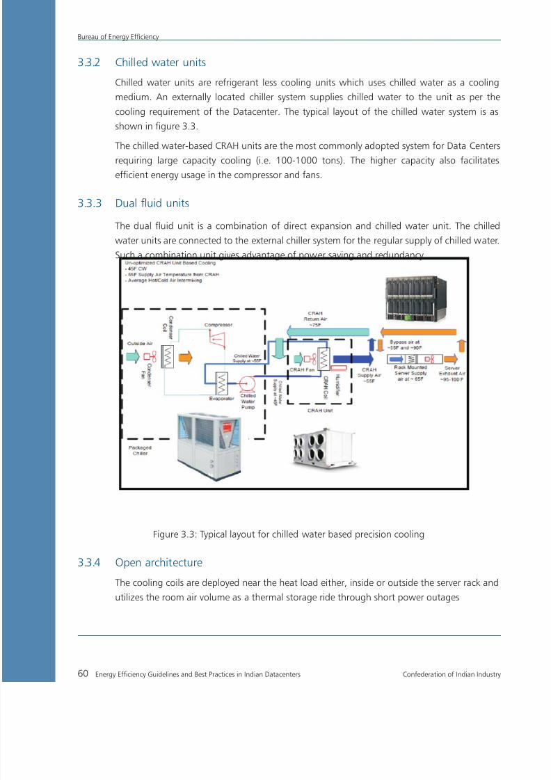
8/12/2019 CII & BEE Data Center Book
http://slidepdf.com/reader/full/cii-bee-data-center-book 80/250
Bureau of Energy Efficiency
60 Energy Efficiency Guidelines and Best Practices in Indian Datacenters Confederation of Indian Industry
3.3.2 Chilled water units
Chilled water units are refrigerant less cooling units which uses chilled water as a cooling
medium. An externally located chiller system supplies chilled water to the unit as per the
cooling requirement of the Datacenter. The typical layout of the chilled water system is as
shown in figure 3.3.
The chilled water-based CRAH units are the most commonly adopted system for Data Centers
requiring large capacity cooling (i.e. 100-1000 tons). The higher capacity also facilitates
efficient energy usage in the compressor and fans.
3.3.3 Dual fluid units
The dual fluid unit is a combination of direct expansion and chilled water unit. The chilled
water units are connected to the external chiller system for the regular supply of chilled water.
Such a combination unit gives advantage of power saving and redundancy.
Figure 3.3: Typical layout for chilled water based precision cooling
3.3.4 Open architecture
The cooling coils are deployed near the heat load either, inside or outside the server rack and
utilizes the room air volume as a thermal storage ride through short power outages

8/12/2019 CII & BEE Data Center Book
http://slidepdf.com/reader/full/cii-bee-data-center-book 81/250
Confederation of Indian Industry Energy Efficiency Guidelines and Best Practices in Indian Datacenters 61
Bureau of Energy Efficiency
3.3.5 Closed architecture
The cooling coils are deployed inside a fully enclosed rack
Figure 3.4: Open and closed Architecture
Table 3.1: Advantages & disadvantages for different configuration:
Open vs.ClosedCooling Architecture SystemComparison
Open Architecture System
Advantages
0 Ride-through/redundancy on room level0 Lower first cost and lower operating cost0 No limits on rack selection0 Self regulating capacity
Disadvantages
0 Higher audible noise0 Mainly a room solution
Closed Architecture System
Advantages
0 Low audible noise0 Deployable as a single rack
Disadvantages
0 Shorter ride-throught time oncooling system loss
0 Higher first cost0 Fixed capacity
PumpedRefrigerantBased vs.Water-Based SystemComparison
Pumped Refrigerant Based System
Advantages
0 No water in data center - No risk if a leak occurs0 Higher energy efficiency0 Smaller piping requirements
Disadvantages
0 Possible compatibility issues with small rooms0 Higher fluid cost0 Piping must be overhead
Water-Based System
Advantages
0 Lower fluid cost0 No limitation to room size
Disadvantages
0 Water damage risk if a leak occurs0 May require fluid treatment to
prevent fouling0 Limited overhead cooling options
3.4 Precision Air Conditioner (PAC)
The following are some of the key features of PAC over comfort cooling systems.
Some of the key differences between Precision Air and Comfort Air conditioning are highlighted
in table 3.2.

8/12/2019 CII & BEE Data Center Book
http://slidepdf.com/reader/full/cii-bee-data-center-book 82/250
Bureau of Energy Efficiency
62 Energy Efficiency Guidelines and Best Practices in Indian Datacenters Confederation of Indian Industry
Table 3.2: Key differences between Precision Air and Comfort Air conditioning
Parameters Precision Comfort
Sensible Heat Ratio 0.90 - 0.95 0.70
Temperature Control +_ 10c +_ 30c
Humidity Control +_ 5% RH No control
Operating Hours 8760/annum 2000/annum
Air Movement 500 - 650 cfm/TR 300 - 450 cfm/TR
Filtration Efficiency 95% 65%
Built - in redundancy Available Not Available
3.4.1 Sensible Heat Ratio (SHR)
There is a need to ensure the control of conditioned environment due to high levels of heat
generation by the equipment. The heat load on the system can be categorised into sensibleheat and latent heat.
Sensible heat removal or addition causes subsequent changes in dry bulb temperature. Latent
heat load pertains to the amount of moisture content in the air. The total cooling capacity of
a PAC is the summation of both sensible and latent heat.
Total Cooling Capacity = Sensible Cooling + Latent Cooling
The ratio of the sensible cooling capacity to total cooling capacity is turned as Sensible Heat
Ratio (SHR).
Electronic devices generates more sensible heat rather than latent heat. The Precision Air
Conditioner provides about 0.9SHR, which suits the cooling requirement of the electronic
devices. The comfort-cooling machine provides about 0.65 to 0.7SHR, which is suitable for
human comfort as shown in Figure 3.4a.
Figure 3.4a : Sensible Heat Ratio
General Office
1.0
.65
1.0
.90
Sensible Heat Ratio
Computer Office
A Precision Air Conditioner is designed for higher sensible heat ratio which suits
the cooling requirement of electronic devices

8/12/2019 CII & BEE Data Center Book
http://slidepdf.com/reader/full/cii-bee-data-center-book 83/250
Confederation of Indian Industry Energy Efficiency Guidelines and Best Practices in Indian Datacenters 63
Bureau of Energy Efficiency
3.4.2 Precise Temperature and Humidity
A key advantage benefit of the PAC is its ability to control temperature precisely. The control
is provided by the microprocessor which response quickly to variations and maintains less
tolerances which is a requisite for a stable environment. Precision Air Conditioners typically
include several stages of cooling or heating and humidification or dehumidification cycles
which alows it to satisfy all ranges of temperature and humidity requirements.
3.4.3 Protection against airborne contaminants (Air Quality)
With most critical equipment housed either in remote locations or in dedicated server rooms,
there is an increasing need to ensure superior air quality while also ensuring less downtime.
Further, the precision cooling equipment allows air to flow through filters ensuring a cleanerenvironment. Precision Air Conditioners typically use deep-pleated filter bank having moderate
to high efficiency to minimize airborne particles. The precision air conditioning equipment is
capable of providing air filtration efficiency of 95% upto 5-micron sizes.
3.5 Criteria for cooling system design
The following are some of the basic criteria for designing the cooling solution for Datacenter. These
criteria have been developed based on the discussions with the experts, consultants, equipment suppliers
and users of datacenter. These can be used as a guideline while designing new datacenters.
3.5.1 Load density
The high concentration of equipment can result in significant increase of load density in an IT
room/ Datacenter as compared to a typical office. Therefore, it is vital to build a system that can
keep a steady check on the load density. load. Load density is a crucial parameter to be monitor,
which has effect on sensible cooling requirement and air distribution pattern.
The typical Load Density values are as under;
Office - 5 – 15 watts / sq. ft. (54 – 161 watts / sq. m)
IT Room/Datacenter - 50 – 200 watts / sq. ft. (538 – 2,153 watts / sq. m)
3.5.2 Temperature and Humidity
The temperature and relative humidity are extremely important because it impacts the reliability
and optimum operation of all equipment in a datacenter. The typical design conditions
recommended are 72-75°F (22-24°C) and 45-50% R.H.
Precision Air Conditioners operate at a high air-flow rate per unit of heat
removed. Generally, 160 CFM (76 lps) per kW or greater

8/12/2019 CII & BEE Data Center Book
http://slidepdf.com/reader/full/cii-bee-data-center-book 84/250
Bureau of Energy Efficiency
64 Energy Efficiency Guidelines and Best Practices in Indian Datacenters Confederation of Indian Industry
3.5.3 Air quantity
The high CFM / kW (Lps / kW) inherent to precision systems contribute to the high sensible
heat ratio, improved air distribution, and increased filtration rates.
Since the Datacenter load is highly varying in nature, the quantity of cold air supplied should
also be varied based on the cooling requirement. A typical design air quantity should be 500-650 cfm/TR.
3.5.4 Air cleanliness
Since, airborne dust can damage equipment, therefore filters are extremely important for dust
free operation of the datacenter. Filters should be deep pleated and operated with low face
velocities which would increase its effectiveness. The filter efficiency should be 95% upto 5µ
particle size.
3.5.5 Vapor barrier
As almost all construction materials are transparent to moisture, a well-designed technology
room must include a vapor barrier. Without a vapor barrier, the technology room will lose
humidity in winter and will gain it in summer. This makes humidity set point control very
difficult and increases the run times of compressors and humidifiers. Improving the vapor
barrier helps in minimizing the energy waste.
To create an effective vapor barrier, ceilings should be sealed with material such as a polyethylene
film, concrete walls should be painted with a rubber or plastic base paint, doors should seal
tightly, and all pipes and cable penetrations should be sealed.
3.5.6 Redundancy
Redundancy is achieved by providing additional or standby unit that provides the required
cooling capacity even after shutdown/ failure of one or more units. The cost of redundancy
should be considered against the projected cost of downtime in technology room.
However, the difference between redundancy and over-design should be addressed
to avoid in efficient operation of systems. A run-time-based operation of equipment and
automatic control of operation are required for optimum operation of standby equipment.
3.5.7 Access control for parameter setting
The security of the air conditioners is as important as that of the hardware equipments in the
technology room. The indoor units must be located within the technology room and should
be placed within the same restricted access as the IT hardware. The outside heat rejection
equipment should be placed on a roof or some other secure area within the facility in order

8/12/2019 CII & BEE Data Center Book
http://slidepdf.com/reader/full/cii-bee-data-center-book 85/250
Confederation of Indian Industry Energy Efficiency Guidelines and Best Practices in Indian Datacenters 65
Bureau of Energy Efficiency
to keep the inner area secure. The access should be restricted other than the manager of
Data Center. The access to set the operating values of key parameters should be password
protected. Otherwise, it may lead to malfunction / inefficient operation of the system.
The cooling unit must be password protected so that no one can change the performance
settings, which can lead to malfunction, & downtime.
3.6 The process of cooling in a Datacenter
The process of cooling used has a major impact on the energy efficiency of the datacenter. Two
types of configurations namely conventional room cooling system and Hot aisle / Cold aisle
approach are used in datacenters. The Hot aisle/Cols aisle configuration is the latest system
and is more energy efficient in compared to the conventional room cooling system.
Figure 3.5: A typical layout of hot aisle and cold aisle approach
In the figure above, the racks are arranged such that the hot side and cold side of racks face
each other to form alternative cold and hot aisles.
The cold aisle consists of perforated floor tiles separating two rows of racks. The chilled air from theperforated floor tiles is supplied to front of the racks. The inlets of each rack face the cold aisle. This
arrangement ensures that the hot air exhausted from the rear of the racks is returned only to the
PAC. Hence, it becomes very important to make available ample amount of cold air to the racks.
Higher perforation levels (Ideally up to 83%) on the rack door enable better airflow.

8/12/2019 CII & BEE Data Center Book
http://slidepdf.com/reader/full/cii-bee-data-center-book 86/250
Bureau of Energy Efficiency
66 Energy Efficiency Guidelines and Best Practices in Indian Datacenters Confederation of Indian Industry
3.7 Determining heat output of a system
The total heat output is the summation of the heat dissipated by individual components of
datacenter. The components include IT equipment, UPS, Power Distribution devices, Precision
Air Conditioning Units, Lighting, and operating personnel.
The heat output of UPS and Power Distribution systems consists of a fixed loss and a lossproportional to operating power. These losses are sufficiently consistent across various brands
and models and so they can be approximated without significant error. The load due to Lighting
and human load can also be readily estimated using standard values.
A detailed thermal analysis using thermal output data for every item in the Datacenter is
possible, but a quick estimate using simple technique gives results that are within the typical
margin of error compared to a complicated detailed analysis. The quick estimate can be
performed by anyone with specialized knowledge.
3.8 Cable management
The increase in server population impose challenge for better cable management in Datacenter.
If not properly managed, cables can obstruct airflow through perforated floor tiles. Inspect the
under-floor plenum to determine if cabling or piping is obstructing the airflow. Overhead
cabling is becoming increasingly popular, which eliminates the chances for obstruction of
airflow. Deeper racks are now available to allow for increased airflow. Existing racks can be
equipped with expansion channels to add depth for cables as well as airflow.
3.9 Measures for Energy conservation in Air-Conditioning system
Some of the energy saving opportunities available in the datacenter cooling system are detailed below.
3.9.1 The chiller system
Energy saving measure 1:
Increase the Chilled Water Supply Temperature (CHWST) Set point
The chilled water supply temperature (CHWST) set point is specified during the designing of
a cooling system. The chilled water supply temperature has a direct impact on the operating
efficiency of the chiller. As a rule of thumb, chiller efficiency improves by 1% for every 1OF
increase in the evaporator-leaving water temperature, all other factors held constant.
Chiller efficiency improves by 1% for every 1OF raise in the temperature of
water leaving the evaporator with all other factors held constant

8/12/2019 CII & BEE Data Center Book
http://slidepdf.com/reader/full/cii-bee-data-center-book 87/250

8/12/2019 CII & BEE Data Center Book
http://slidepdf.com/reader/full/cii-bee-data-center-book 88/250
Bureau of Energy Efficiency
68 Energy Efficiency Guidelines and Best Practices in Indian Datacenters Confederation of Indian Industry
Energy saving measure 3:
Implement variable condenser cooling water flow
The standard procedure for operating water-cooled chillers is to maintain constant condenser
water (CW) flow and a constant temperature of water entering the condenser, referred as
condenser cooling water temperature (CCWT).
Reducing the condenser water flow will reduce pumping energy consumption. However,
reducing the condenser water flow would increase the condensing temperature, causing the
chiller to operate inefficiently. The lower condenser cooling water temperature will reduce the
chiller condensing temperature resulting in efficient operation. The benefits must be compared
against the increased cooling tower fan energy needed to produce lower condenser cooling
water temperature.
The following points have to be considered to evaluate the possibility of achieving energy
savings by reducing condenser water flow: .ASHRAE recommendation of minimum condenser water flow velocity of 1 m/s to maintain=
turbulent velocity and prevent formation of deposits in the condenser
The condenser water velocity is only a small factor in the overall heat transfer. The main=
factor controlling refrigerant condensation is the condenser surface area
Many chillers can operate at low condenser water flow velocities and high condenser=
water ∆T without affecting the stable operation of the chiller
Decreasing the condenser water flow rate will provide condenser water pump energy saving
that may or may not outweigh the increased chiller energy use.
It is recommended that the condenser cooling water temperature (CCWT) should be kept as
low as possible to maintain better chiller efficiency.
Energy saving measure 4:
Install an Evaporative-Cooled-condenser for chillers
Evaporative-cooled chillers are essentially water-cooled chillers in a package. The system has a
condenser, water, sump and pump, etc., all as integral parts of the chiller.
The hot gaseous refrigerant is condensed by the water which flows through the condensertubes. It facilitates the condensing temperature to be at ambient wet bulb temperature, as in
water-cooled chiller.
This system improves the operating efficiency of the chiller significantly as compared to an
aircooled chiller and also reduces the power consumption of cooling water pumping system.
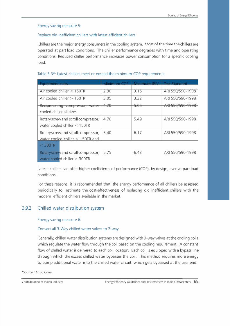
8/12/2019 CII & BEE Data Center Book
http://slidepdf.com/reader/full/cii-bee-data-center-book 89/250
Confederation of Indian Industry Energy Efficiency Guidelines and Best Practices in Indian Datacenters 69
Bureau of Energy Efficiency
Energy saving measure 5:
Replace old inefficient chillers with latest efficient chillers
Chillers are the major energy consumers in the cooling system. Most of the time the chillers are
operated at part load conditions. The chiller performance degrades with time and operating
conditions. Reduced chiller performance increases power consumption for a specific coolingload.
Table 3.3*: Latest chillers meet or exceed the minimum COP requirements
Equipment class Minimum COP Minimum IPLV Test Standard
Air cooled chiller < 150TR 2.90 3.16 ARI 550/590-1998
Air cooled chiller > 150TR 3.05 3.32 ARI 550/590-1998
Reciprocating compressor, water
cooled chiller all sizes
4.20 5.05 ARI 550/590-1998
Rotary screw and scroll compressor,
water cooled chiller < 150TR
4.70 5.49 ARI 550/590-1998
Rotary screw and scroll compressor,
water cooled chiller > 150TR and
< 300TR
5.40 6.17 ARI 550/590-1998
Rotary screw and scroll compressor,
water cooled chiller > 300TR
5.75 6.43 ARI 550/590-1998
Latest chillers can offer higher coefficients of performance (COP), by design, even at part load
conditions.
For these reasons, it is recommended that the energy performance of all chillers be assessed
periodically to estimate the cost-effectiveness of replacing old inefficient chillers with the
modern efficient chillers available in the market.
3.9.2 Chilled water distribution system
Energy saving measure 6:
Convert all 3-Way chilled water valves to 2-way
Generally, chilled water distribution systems are designed with 3-way valves at the cooling coils
which regulate the water flow through the coil based on the cooling requirement. A constant
flow of chilled water is delivered to each coil location. Each coil is equipped with a bypass line
through which the excess chilled water bypasses the coil. This method requires more energy
to pump additional water into the chilled water circuit, which gets bypassed at the user end.
*Source : ECBC Code

8/12/2019 CII & BEE Data Center Book
http://slidepdf.com/reader/full/cii-bee-data-center-book 90/250

8/12/2019 CII & BEE Data Center Book
http://slidepdf.com/reader/full/cii-bee-data-center-book 91/250
Confederation of Indian Industry Energy Efficiency Guidelines and Best Practices in Indian Datacenters 71
Bureau of Energy Efficiency
common. This arrangement eliminates the primary chilled water pumps (the pumps previously
designated as secondary become the primary pumps) which results in energy savings.
Chillers still have minimum allowable evaporator flow rates; the control system must monitor
and ensure these rates. Even in facilities with relatively constant load such as Datacenters,
energy savings can be realized as the constant self-balancing of the primary-only control
system minimizes pump energy use.
Energy saving measure 9:
Install high efficiency pumps
Presently, pumps are available with higher efficiencies, upto 85%. Appropriate high-efficiency
pumps can be selected by matching their duty point to operating parameter values such as
maximum head and flow requirements in the pumping system.
Estimate the operating parameters such as maximum head and flow requirement and select
a high efficient pump matching its duty point close to the operating values.
Energy saving measure-10:
Calibrate Chilled Water (CHW) supply temperature sensors annually
Chiller efficiency is highly dependent on chilled water (CHW) temperature and ambient
conditions.
A low chilled water supply temperature typically results in lower chiller efficiency, with other
factors remains constant. An error in the chilled water supply temperature sensor can cause
a chiller plant to produce chilled water at low temperature which may not be required and
increase the energy consumption. In addition, a too-cold chilled water temperature can causeundesired dehumidification at the cooling coils. This places an extra load on the cooling
system and additional energy use.
Therefore, it is recommended to calibrate the sensors periodically, preferrably on an annual
basis.
Energy saving measure 11:
Calibrate the Condenser Water (CW) supply temperature sensors annually
The temperature of the condenser water (CW) entering the condenser has major effect onchiller efficiency. A higher condenser water supply temperature typically results in lower chiller
efficiency, with other factors being constant.
An error in the condenser water supply temperature sensor can cause the cooling towers to produce
warmer condenser water than desired and in turn cause inefficient operation of the chiller plant.
Hence it is recommended to calibrate the condenser water supply sensors annually.

8/12/2019 CII & BEE Data Center Book
http://slidepdf.com/reader/full/cii-bee-data-center-book 92/250
8/12/2019 CII & BEE Data Center Book
http://slidepdf.com/reader/full/cii-bee-data-center-book 93/250
Confederation of Indian Industry Energy Efficiency Guidelines and Best Practices in Indian Datacenters 73
Bureau of Energy Efficiency
It is recommended to monitor Return Temperature Index (RTI) and Rack Cooling Index (RCI) to
maintain energy performance of the cooling system.
Energy saving measure 15:
Increase the supply air temperature as per ASHRAE recommendations.
A low supply air temperature makes the chiller system less efficient and limits the utilization
of economizers. Enclosed architectures allow the highest supply temperatures since mixing of
hot and cold air is minimized.
In contrast, the supply temperature in open architectures is often dictated by the hottest
intake temperature.
Target the maximum recommended intake temperature from guidelines issued by ASHRAE
(770F) depending on the type of electronic equipment. If the air distribution system can
be modified to deliver air more effectively to the equipment, it may be possible to raise theaverage intake temperature. This in turn will allow the cooling supply air temperature to be
raised, which typically results in a more efficient cooling system operation.
Energy saving measure 16:
Provide Temperature and Humidity Sensors to Monitor IT Equipment air intake Conditions
IT equipment manufacturers design their products to operate reliably within a given range
of intake temperature and humidity. The temperature and humidity limits imposed on the
cooling system that serves the Datacenter are intended to match or exceed the IT equipment
specifications. However, the temperature and humidity sensors are often integral to the
cooling equipment and are not located at the IT equipment intake points. The condition of
the air supplied by the cooling system is often significantly different by the time it reaches the
IT equipment intakes. It is usually not practical to provide sensors at the intake of every piece
of IT equipment, but a few representative locations can be selected.
Adjusting the cooling system sensor locations in order to provide the cooling that is needed at
the IT equipment intake points often results in more efficient operation.
Energy saving measure 17:
Calibrate Temperature and Humidity Sensors annually
Temperature sensors generally have good accuracy when they are properly calibrated
(+/- a fraction of a degree), but they tend to drift out of adjustment over time. In contrast, even
the best humidity sensors are intrinsically not very precise (+/- 5% RH is typically the best accuracy
that can be achieved at reasonable cost). Humidity sensors also drift out of calibration.

8/12/2019 CII & BEE Data Center Book
http://slidepdf.com/reader/full/cii-bee-data-center-book 94/250
Bureau of Energy Efficiency
74 Energy Efficiency Guidelines and Best Practices in Indian Datacenters Confederation of Indian Industry
To ensure good cooling system performance, all temperature and humidity sensors used by the
control system should be treated as maintenance items and calibrated at least once a year.
After a regular calibration program has been in effect, monitor and gauge the drift in sensors
to estimate the required frequency of calibration. Calibrations can be performed in-house with
the proper equipment, or by a third-party service.
Energy saving measure 18:
Provide personnel and Cable Grounding to Allow Lower IT Equipment Intake Humidity
Higher humidity levels results in increased energy consumption of cooling system in Datacenter.
Conversely, the lower humidity limit in Datacenters is often set relatively high (40% RH at the
IT equipment intake is common) to guard against damage to the equipment due to Electro
Static Discharge (ESD).
Energy can be saved if the allowed lower humidity limit can be lowered. ESD can be kept
in check by conductive flooring materials, good cable grounding methods, and providing
grounded wrist straps for technicians to use while working on equipment.
3.9.4 Energy Conservation measures in Datacenter Air Management
Energy saving measure 19:
Ensure Adequate Match between Heat Load and Raised-Floor Plenum Height
The cooling capacity of a raised floor depends on its effective flow area, which can be increased
by removing cables and other obstructions that are not in use. Still, the heat density may needto be reduced. Undersized and/or congested plenums often require an overall elevated static
pressure to deliver the required airflow. Providing increased static pressure requires additional
energy consumption in fan.
Energy saving measure 20:
Provide Adequate Ceiling Supply/Return Plenum Height
The plenum height can be increased if a clear ceiling allows it. A return plenum often means
a lower clear ceiling but allows the placing of return grilles directly above the hot aisles. Such
a plenum needs to be maintained like a raised floor. A shallow plenum may result in high
pressure losses, poor pressure distributions, and high fan-energy costs.
Energy saving measure 21:
Remove Abandoned Cables and Other Obstructions
Under-floor and overhead obstructions often interfere with the distribution of cool air. Such
interferences can significantly reduce the air handlers’ airflow as well as negatively affect the
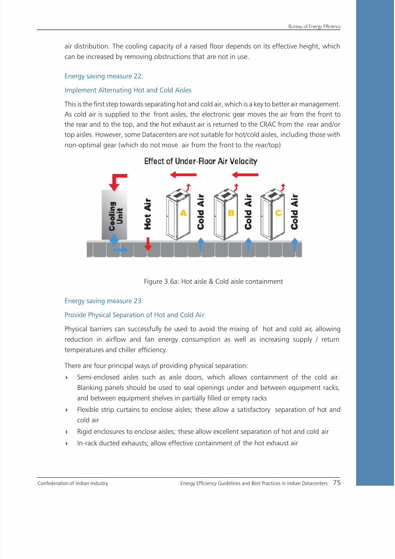
8/12/2019 CII & BEE Data Center Book
http://slidepdf.com/reader/full/cii-bee-data-center-book 95/250

8/12/2019 CII & BEE Data Center Book
http://slidepdf.com/reader/full/cii-bee-data-center-book 96/250
Bureau of Energy Efficiency
76 Energy Efficiency Guidelines and Best Practices in Indian Datacenters Confederation of Indian Industry
Energy saving measure 24:
Provide perforated tiles or diffusers in Cold Aisles
Perforated floor tiles or over-head supply diffusers should only be placed in the cold aisles to
match the “consumption” of air by the electronic equipment. Too little or too much supply air
results in poor overall thermal and/or energy consumption conditions.
Note that the hot aisles are supposed to be hot, and perforated tiles should not be placed in
those areas.
Energy saving measure 25:
Design the Return Air from Hot Aisle area
The thermal efficiency of the Datacenter increases when the return temperature is maximized.
The closer the return is located to the heat source, the better. If a return plenum is used, the
grills should be placed directly above the hot aisles.
Energy saving measure 26:
Provide Adequate Floor Plenum Pressure
A high static pressure often results in high floor leakage and by-pass air. A moderate static pressure
(0.05 in. of water) allows relatively high tile airflow rates inducing minimum floor leakage.
Energy saving measure 27:
Balance the Air Distribution System
Over-head ducted systems can be adequately balanced using conventional methods whereas
raised-floor systems are balanced by providing the required number of perforated tiles. The
amount of cold air required at each rack should be supplied by placing the adequate number
of tiles in front of racks.
Energy saving measure 28:
Remove Doors from IT Equipment Racks
The use of doors often obstructs the cooling airflow and may result in recirculation of cooled air
within the enclosed cabinet. This would further increase the equipment intake temperature.
In case the standard 25% perforated tile does not deliver enough airflow to cool the
equipment at moderate pressure, it is better to increase the tile open area than to
increase the pressure.

8/12/2019 CII & BEE Data Center Book
http://slidepdf.com/reader/full/cii-bee-data-center-book 97/250
Confederation of Indian Industry Energy Efficiency Guidelines and Best Practices in Indian Datacenters 77
Bureau of Energy Efficiency
If rack doors are necessary for security reasons, sufficient openings should be provided in the
doors to permit adequate airflow through it.
Energy saving measure 29:
CFD analysis for better air management
Optimizing Cooling performance for a Datacenter is a challenging task. Several factors affect
the airflow distribution and the cooling performance of a Datacenter. Physical measures and
field-testing are time and labor Intensive. In such situation, Computational Fluid Dynamics (CFD)
simulations provides a feasible alternative for testing various design layouts and configuration
in a relatively short time.
CFD can predict the air velocities, pressure, and temperature distribution in the entire Datacenter
facility. A good design of layout and equipment can contribute upto 30% saving in operational
energy consumption.
Energy saving measure-30:
Switch off CRAC/CRAH Units
In case of low heat load on all the CRAC units, some of the CRAC units can be turned off. Few of
the OEM focus on advance options with the use of intelligent controllers. It enables the function of
multiple units in team mode configuration and optimizes the energy consumption. The operational
control for the units can be set by the operating personnel.
Experimentation may be required to determine the units to be operated in ON/OFF mode
without compromising on the cooling of the IT equipment
Energy saving measure-31:
Control all supply fans parallelly
If all the supply fans serving a given space are identical and equipped with variable speed drives, fan
energy is minimized by running all the fans (including redundant units) at the same speed
Energy saving measure-32:
Install CRAC units with EC fans
When replacing older units, new units that use EC fans for air movement application should
be insisted upon. EC fans provide electronic control to vary the air flow rate and maintain
the required temperature at the IT equipment. They use the minimum energy for operation
compared to other air movement equipment available in the market.
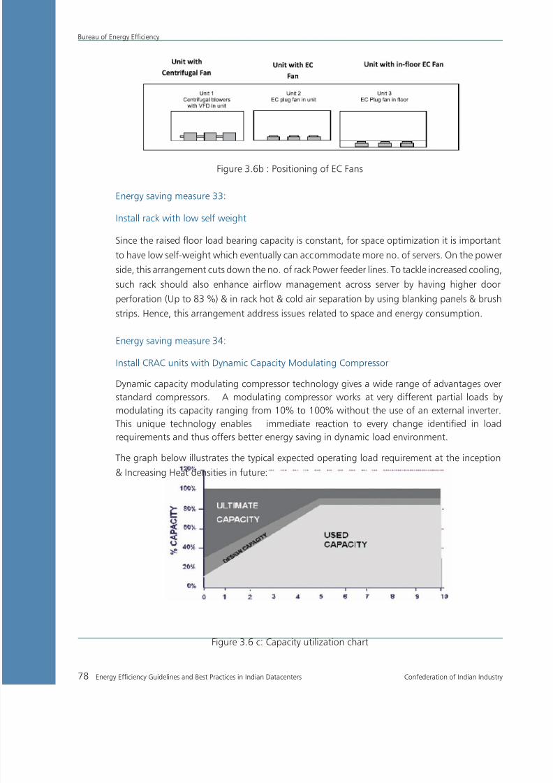
8/12/2019 CII & BEE Data Center Book
http://slidepdf.com/reader/full/cii-bee-data-center-book 98/250
Bureau of Energy Efficiency
78 Energy Efficiency Guidelines and Best Practices in Indian Datacenters Confederation of Indian Industry
Figure 3.6b : Positioning of EC Fans
Energy saving measure 33:
Install rack with low self weight
Since the raised floor load bearing capacity is constant, for space optimization it is important
to have low self-weight which eventually can accommodate more no. of servers. On the power
side, this arrangement cuts down the no. of rack Power feeder lines. To tackle increased cooling,such rack should also enhance airflow management across server by having higher door
perforation (Up to 83 %) & in rack hot & cold air separation by using blanking panels & brush
strips. Hence, this arrangement address issues related to space and energy consumption.
Energy saving measure 34:
Install CRAC units with Dynamic Capacity Modulating Compressor
Dynamic capacity modulating compressor technology gives a wide range of advantages over
standard compressors. A modulating compressor works at very different partial loads by
modulating its capacity ranging from 10% to 100% without the use of an external inverter.This unique technology enables immediate reaction to every change identified in load
requirements and thus offers better energy saving in dynamic load environment.
The graph below illustrates the typical expected operating load requirement at the inception
& Increasing Heat densities in future:
Figure 3.6 c: Capacity utilization chart

8/12/2019 CII & BEE Data Center Book
http://slidepdf.com/reader/full/cii-bee-data-center-book 99/250
Confederation of Indian Industry Energy Efficiency Guidelines and Best Practices in Indian Datacenters 79
Bureau of Energy Efficiency
So the dynamic capacity modulating compressor takes care of the requirement in a energy
efficient manner over a larger period.
Energy saving measure-35:
Optimizing Airflow
It is quite important to know that about 12-14% of the total power consumption is used for
Airflow while cooling a data centre. So, due concentration is to be given towards optimizing
the Airflow within the data centre space by:
Reducing the airflow obstacles/restrictions to save energy=
Minimizing the short-circuiting between hot and cold air by using blanking plates where=
appropriate
Proper placement of racks is important to reduce short-circuiting of hot and cold air.=
Therefore, we need to arrange the racks in hot-aisle /cold-aisle configuration. High-density
racks are to be placed at the centre of the rack
Place cooling unit at the end of the hot aisle for better control of return air temperature=
Improve vapor barrier i.e. unnecessary humidification/dehumidification is avoided to=
minimize the energy waste
Focus on reducing the solar heat gain by checking on air leakages in the room under=
floor & ceiling to further minimize energy waste
Today, there are companies that offer solutions that optimize the airflow and take care
of each aspect towards increasing overall efficiency of a data centre
Energy saving measure-36:
Using Economizers appropriately
In many locations, outside cool air can be used to supplement Datacenter cooling and provide
“free cooling” during colder months. This is accomplished by using economizer systems.
The Energy Usage Intensity (EUI) of buildings with economizers was 13 percent lower than
those without economizers.
Energy saving measure-37:
Bringing cooling closer to the source of heat
The cornerstone of an effective cooling strategy is to take care of every possible heat load in
a Datacenter, but due to rapid increase in technology & heat loads, the dependence solely
on conventional mission-critical cooling systems to resolve such high heat densities is not
possible. Hot spots or zones require targeted cooling solutions. In addition, for extremely
high heat loads, conventional approaches may simply take up too much floor space to make
it possible.

8/12/2019 CII & BEE Data Center Book
http://slidepdf.com/reader/full/cii-bee-data-center-book 100/250
Bureau of Energy Efficiency
80 Energy Efficiency Guidelines and Best Practices in Indian Datacenters Confederation of Indian Industry
Supplemental cooling is a relatively new approach to Datacenter cooling and this has been
gaining rapid acceptance as Datacenter managers seek solutions to help them to:
Overcome cooling capacity limitations of raised floor systems in high heat density=
applications
Increase cooling system efficiency and flexibility=
Overhead coolers can be located over the rack and/or at the center of the cold aisle receiving
hot air from the hot aisle and supply the cold air into the cold aisle.
Thus, supplemental cooling solutions are space saving as well as provide low risk & increased
reliability for the today’s Datacenters.
Together, these methods can reduce cooling system energy costs by 30 to 45 percent and
generate significant, recurring saving.
Presently, the main objective of IT vendors is to crunch-in more and more compute capability
in the available small space. As discussed earlier, gradually the heat density of Datacenters
is increasing. There is also indiscriminate increase in power tariffs. Therefore, increase in theoperational expenditure is certain. Thus, reduction in energy consumption and increasing
energy-efficiency are the important aspects to focus on for Datacenter managers.

8/12/2019 CII & BEE Data Center Book
http://slidepdf.com/reader/full/cii-bee-data-center-book 101/250
Confederation of Indian Industry Energy Efficiency Guidelines and Best Practices in Indian Datacenters 81
Bureau of Energy Efficiency
Case Study 4
POTENTIAL BENEFITS OF ECONOMIZER IN COOLING SYSTEM
BackgroundA precise control of temperature and humidity control is essential for efficient Datacenter operation. The
increasing energy costs challenge engineers to find the most cost-effective ways to control temperature
and humidity within acceptable ranges.
The use of economizer systems is one method that has been adopted to lower energy usage, lessen
wear and tear on precision air conditioning equipment and decrease operational costs.
Economizer systems are designed to utilize outdoor favorable weather to supplement the cooling
requirements and provide so-called “free cooling” cycles for computer rooms and Datacenters. The
economizer system minimizes or eliminates the operation of mechanical cooling system.
Economizer using ambient air
The economizer uses fresh air directly to supplement the mechanical cooling system. The system requires
hot aisle configuration while the air from the hot aisle would be taken to outside through ducting under
the specified economizer operating condition.
It would be possible to remove the entire heat generated by supplying high volume of fresh air, if it
satisfies the required supply air conditions.
The economizer would be operated at three different conditions based on the ambient air conditions,
and are discussed below.
Case-1: Fresh air temperature higher than return air temperature
The system fully operates with mechanical cooling system. Since the outside air temperature is higher
than the return air temperature. There will be no use in bringing the fresh air inside.

8/12/2019 CII & BEE Data Center Book
http://slidepdf.com/reader/full/cii-bee-data-center-book 102/250
Bureau of Energy Efficiency
82 Energy Efficiency Guidelines and Best Practices in Indian Datacenters Confederation of Indian Industry
Case-2: Fresh air temperature between supply and return air temperature
The system would operate with full fresh air drawn from ambient since the outside air is cooler than the
return air from the hot aisles. The load on the mechanical cooling system will be directly proportional to
the fresh air temperature i.e. at 27ºC it will be 100%, at 22ºC it will be 50% and 17ºC it will be 0%.
Case-3: Fresh air temperature lesser than supply air temperature
In this case, the supply air will be the mix of fresh air and the return air. Since the fresh air is cooler
than the required temperature of supply air, the control dampers are modulated to mix proportionate
amount of fresh air with return air.
If the relative humidity of the return air drops to 20%, then the humidifiers will be run in order to
maintain this percentage as a minimum.
Fluid based EconomizerThe stringent temperature and humidity requirements of Datacenters coupled with the need for
continuous cooling makes the fluid-based economizer system one of the choices for most Datacenters
environment.
The ultimate goal of both air-side and fluid-side economizer systems is to provide “free cooling” to the
facility, thus reducing the operating time of the mechanical cooling system.

8/12/2019 CII & BEE Data Center Book
http://slidepdf.com/reader/full/cii-bee-data-center-book 103/250
Confederation of Indian Industry Energy Efficiency Guidelines and Best Practices in Indian Datacenters 83
Bureau of Energy Efficiency
Figure 3.7: Schematic of Fluid based economizer
In certain geographical locations, economizers can satisfy a large portion of Datacenter coolingrequirements. The use of economizer systems can have a significant impact on energy usage.
In a fluid based economizer, the warm return air from Datacenter enables effective transfer of heat
from air to water maintained at temperatures close to wet bulb temperature. As the heat transfer is
proportional to the temperature difference between cooling water and return air, more heat transfer
takes place in the AHU. As a result, cooling capacity of the air handling coils increases dramatically.
The pre-cooled return air is again cooled to required temperature through chilled water system. Since
the return air is pre-cooled with cooling water the cooling requirement on chilled water system reduces
and minimizes the load on chiller.
Project details
One of the leaders in precision air conditioner manufacturers implemented the project with the fluid
side economizer in the Datacenter deployed with high density IT equipment and blade servers.

8/12/2019 CII & BEE Data Center Book
http://slidepdf.com/reader/full/cii-bee-data-center-book 104/250

8/12/2019 CII & BEE Data Center Book
http://slidepdf.com/reader/full/cii-bee-data-center-book 105/250
Confederation of Indian Industry Energy Efficiency Guidelines and Best Practices in Indian Datacenters 85
Bureau of Energy Efficiency
Case Study 5
INTRODUCTION OF INTELLIGENT CONTROLLER FOR MULTIPLECOMPUTER ROOM AIR CONDITIONER (CRAC) SYSTEM
Background
Most of large Datacenters are equipped with multiple CRAC units to cater the cooling load requirement.
Normally, the CRAC units operate in a decoupled fashion, where the units are controlled by its localized
feed back sensor. Under such conditions, the control of humidity level becomes complex. For instance,
two CRAC units might fight each other; one CRAC unit would dehumidify the air while the other unit
would humidify the air, to control the overall humidity level. This leads to the problem of continuous
operation of both CRAC units consuming more energy.
The problem can occur due to the following reasons.If the return air to the two CRAC units is at slightly different temperatures=
If the calibrations of the two humidity sensors disagree=
If the CRAC units are set to different humidity settings=
The problem can be solved by using an intelligent controller system to control the operation of all CRAC
units.
Measures
The intelligent controllers can be set to operate in any of the following modes to optimize the operation
of all CRAC units.
Teamwork mode
During balanced load conditions units can be grouped together connected to network & can be set up
to work together in a teamwork mode. In this teamwork mode most of the parameters are shared; if
set in any one of the units, all other units will follow with the same settings.
The “Master” unit determines the intense of operation to perform. The master unit evenly distributes
the load among the number of available units.
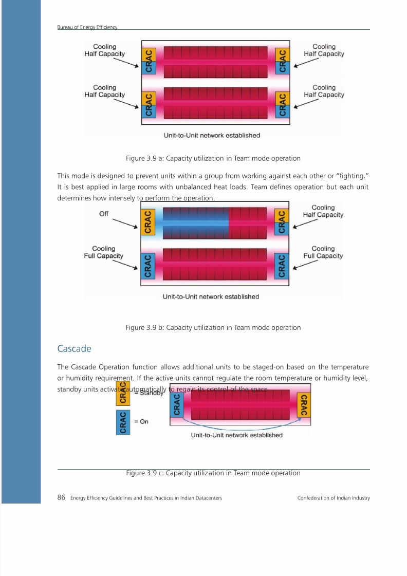
8/12/2019 CII & BEE Data Center Book
http://slidepdf.com/reader/full/cii-bee-data-center-book 106/250
Bureau of Energy Efficiency
86 Energy Efficiency Guidelines and Best Practices in Indian Datacenters Confederation of Indian Industry
Figure 3.9 a: Capacity utilization in Team mode operation
This mode is designed to prevent units within a group from working against each other or “fighting.”
It is best applied in large rooms with unbalanced heat loads. Team defines operation but each unit
determines how intensely to perform the operation.
Figure 3.9 b: Capacity utilization in Team mode operation
Cascade
The Cascade Operation function allows additional units to be staged-on based on the temperature
or humidity requirement. If the active units cannot regulate the room temperature or humidity level,
standby units activate automatically to regain its control of the space.
Figure 3.9 c: Capacity utilization in Team mode operation
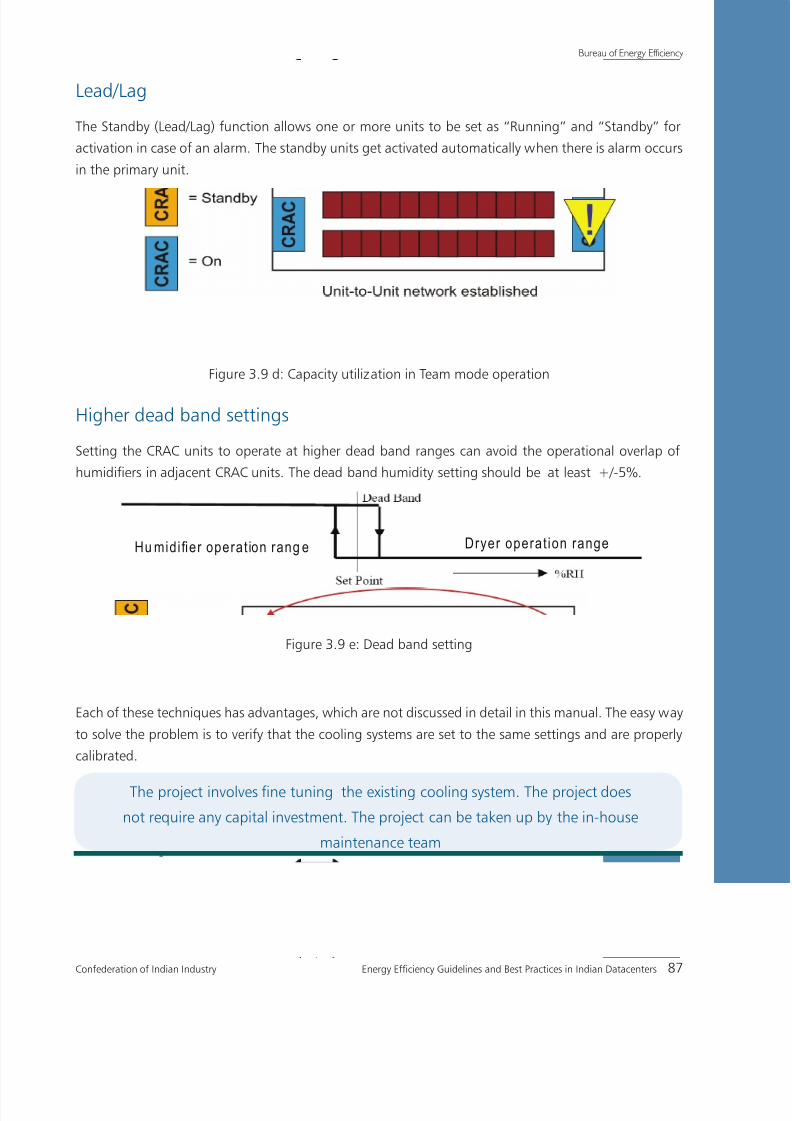
8/12/2019 CII & BEE Data Center Book
http://slidepdf.com/reader/full/cii-bee-data-center-book 107/250
Confederation of Indian Industry Energy Efficiency Guidelines and Best Practices in Indian Datacenters 87
Bureau of Energy Efficiency
Lead/Lag
The Standby (Lead/Lag) function allows one or more units to be set as “Running” and “Standby” for
activation in case of an alarm. The standby units get activated automatically when there is alarm occurs
in the primary unit.
Figure 3.9 d: Capacity utilization in Team mode operation
Higher dead band settings
Setting the CRAC units to operate at higher dead band ranges can avoid the operational overlap of
humidifiers in adjacent CRAC units. The dead band humidity setting should be at least +/-5%.
Hu midi fier operat ion rang e Dryer operat ion range
Figure 3.9 e: Dead band setting
Each of these techniques has advantages, which are not discussed in detail in this manual. The easy way
to solve the problem is to verify that the cooling systems are set to the same settings and are properly
calibrated.
The project involves fine tuning the existing cooling system. The project does
not require any capital investment. The project can be taken up by the in-house
maintenance team

8/12/2019 CII & BEE Data Center Book
http://slidepdf.com/reader/full/cii-bee-data-center-book 108/250
Bureau of Energy Efficiency
88 Energy Efficiency Guidelines and Best Practices in Indian Datacenters Confederation of Indian Industry
Case Study 6
BENEFITS OF ELECTRONICALLY COMMUTTED (EC) FANS FORVARYING AIR REQUIREMENT
The Datacenter cooling system is a primary target for energy efficiency improvements. Air management
is one of the critical areas in Datacenter cooling systems.
The supply air requirement is based on the heat load and also depends upon the operation of the Datacenter.
It becomes difficult to vary air movement in Datacenter by using conventional centrifugal fans. Electronically
commuted (EC) fan is the latest system for varying air movement application in the Datacenter.
EC fans consume up to 15% less power than the conventional centrifugal fans by design. The EC
fans have high efficiency across a wide speed range, whereas the efficiency of the centrifugal fans
rapidly drops with decreasing speed. At partial load range, the benefit of the EC technology gets moreprominent.
The efficiency of the EC motor (typically > 90%) is higher than that of traditional asynchronous AC motor
(typically < 80%) and generates less heat, as there are no slip losses and less copper & iron losses.
Advantages with EC Fan:High efficiency, External rotor EC Motor with integrated Electronics=
No belt losses=
True soft start characteristics ( in rush current lower than operating=
Current)
Maintenance free design & construction=
Back Ward curve , Corrosion resistance aluminum Wheel=
Technical details:
On chilled water cooling units, the fan consumes the maximum the energy usage. Using electrically
commutated (EC) plug fans provides option for improving energy efficiency by controlling the fan speed.
If cooling units are oversized, the fan speed can be reduced. The motor power varies with the cube of
the motor speed.
For example, a 10 percent reduction in fan speed results in an energy savings of 27 Percent. A 20 percent
reduction in fan speed results in 49 percent energy saving. In order to prevent over-dehumidification, the
water flow rate to the chilled water coil should also be reduced by the same percent as the fan speed.
Motor kW2 = Motor kW1 * (speed2/speed1)3
Figure 3.10a: Unique "In-Floor" Configuration

8/12/2019 CII & BEE Data Center Book
http://slidepdf.com/reader/full/cii-bee-data-center-book 109/250
Confederation of Indian Industry Energy Efficiency Guidelines and Best Practices in Indian Datacenters 89
Bureau of Energy Efficiency
Based on the study, the following observations were made.
Scenario 1: Centrifugal Blowers vs. EC Plug Fan Mounted in the Unit
Precision Unit, 72F/50%RH, 45EWT, 10 deg water
TD, 0.3” Externalstatic
Net Sensible CoolingCapacity (KBTUH)
MotorKW
EER CFMSaving from
Base
100% SpeedCentrifugal blowers w/VFD 284 11 25.8 17,000 -
EC motorized impellar 291 9 32.3 17,000 -18.20%
Using ASHRAE 127-2007, the tested EC plug fans mounted inside the precision air conditioning units
draw 18.2 percent less power than the tested centrifugal fan.
Scenario 2: Centrifugal Blowers vs. EC Plug Fan Mounted in the Unit vs. EC Plug Fan Mounted Under
the Unit
Precision Unit, 72F/50%RH, 45EWT, 10 deg water
TD, 0.3” ExternalstaticNet Sensible Cooling Motor KW EER CFM
Saving fromBase
100% Speed
Centrifugal blowers w/VFD 284 11 25.8 17,000 -
EC motorized impellar 291 9 32.3 17,000 -18.20%
EC plug fan under floor 296 7.6 38.9 17,000 -30.90%
Mounting EC plug fans under the Floor is approximately 12 percent more energy efficient than mounting
the EC plug fan inside.
The energy analysis: (EC Fan configuration details)
= Qty 3 Centrifugal Blower = Qty 3 motorized impellerinside unit
= Qty 3 motorizedimpeller under floor
= Belt driven common shaft = Direct drive = Direct drive
= 16300 CFM = 16400CFM = 16400CFM
= 8.6kW = 6.9 kW = 5.5 kW
= Approx annual operatingcost 362500
= Approx annual operatingcost 300000`
= Approx annualoperating cost 237500
Figure 3.10 b: EC Fan configuration details
Cost of Power is Rs. 5 per kWh & operation at 80 % fan speed.
8/12/2019 CII & BEE Data Center Book
http://slidepdf.com/reader/full/cii-bee-data-center-book 110/250
Bureau of Energy Efficiency
90 Energy Efficiency Guidelines and Best Practices in Indian Datacenters Confederation of Indian Industry
Replication potential
The project has a high replication potential and can be done at the designing stage of the project.
Cost Benefits of the project
Annual benefits of Saving of Opex =
Reduction in power consumption=
Improved efficiency & reliability=
The advantages of Electronically Commutated (EC) fans for CRAC units are
applicable in all types of Datacenter
The project has to taken up during the design stage of the cooling infrastructure

8/12/2019 CII & BEE Data Center Book
http://slidepdf.com/reader/full/cii-bee-data-center-book 111/250
Confederation of Indian Industry Energy Efficiency Guidelines and Best Practices in Indian Datacenters 91
Bureau of Energy Efficiency
Case Study 7
POTENTIAL BENEFITS OF HOT AISLE/COLD AISLE CONTAINMENT
Background:Modern IT equipment takes in cold air through the front and exhausts hot air out of the back.
For example, if the front of the servers and the front of the rack shares the same orientation, then the
user has achieved a consistent airflow direction throughout the row of racks. However, if several parallel
rows of racks are set up in the same orientation, a significant cooling problem arises, as the hot exhaust
air from the first row is sucked into the “cool” air intakes of the servers in the second row of racks. With
each progressive row, the air temperature gets hotter and hotter as hot air passed from one row of
servers down to the next as represented in the figure below.
Figure 3.12a: Temperature difference of air to the server racks
To maintain the server inlet air temperature at farthest row, the overall supply air temperature has to
be maintained very low. Providing low temperature air increases the cooling requirement and thus
increases the operating cost of Datacenter.
Apart from that, the condition is worse when significant hot and cold air mixing occurs in the
Datacenter. Because the lower temperature air returning to the CRAC unit loses more moisture in the
cooling process than the warmer unmixed air would. This requires continuous humidification process tomaintain the humidity level inside the Datacenter. The continuous humidification and dehumidification
process reduces the useful work done by the CRAC/CRAH units.
To overcome the issue, the rows of racks should be oriented so that the fronts of the servers face each
other. In addition, the backs of the rows of racks should also be facing each other. Such orientation
of rows layout is referred to as “hot aisle / cold aisle” system. Such a layout, along with cold air
containment can greatly reduce energy losses and prolong the life of the servers.

8/12/2019 CII & BEE Data Center Book
http://slidepdf.com/reader/full/cii-bee-data-center-book 112/250
Bureau of Energy Efficiency
92 Energy Efficiency Guidelines and Best Practices in Indian Datacenters Confederation of Indian Industry
Various containment and segregation techniques can help minimize the mixing of hot and cold air.
Simple devices such as blanking panels (which fill spaces between rack-mounted equipment), air dams
(which seal the top, bottom, and sides of equipment), and brush grommets, as shown in Figure 3.12b
(which can fill open spaces around floor cable cut-outs, and barriers or cabinet chimneys to contain hot
return air) can help contribute to better air management and improve the cooling efficiency.
Figure 3.12 b : Installation of brush grommets
Advanced approaches such as hot aisle or cold aisle containment can minimize the mixing of hot and
cold air to a large extent. Such strategies allow airflows to be more predictable.
Even Greater Efficiencies achieved can be by Integrating the Cold Aisle Containment Unit to the CRAC.
The integration ensures more than 30% Reduction in CRAC Energy Consumptions.
Higher efficiency can be achieved by integrating the Cold Aisle Containment Unit with the CRAC. The
integration ensures a reduction of more than 30% in CRAC unit energy consumption.
The savings realized would be more if the system satisfies the following criteria:
1. The volume of air in the contained area should be equivalent to the air volume required by the ITequipment to remove the heat generated
2. The inlet temperature of the IT equipment should be set at around 22-23ºC
This can be achieved by adopting modulating EC Fan and Digital Scroll compressors (Direct Expansion
CRAC) / Water Flow (Chilled Water CRAC) through sensor Integration.
Figure 3.13: CAC with Intelligent Controller

8/12/2019 CII & BEE Data Center Book
http://slidepdf.com/reader/full/cii-bee-data-center-book 113/250

8/12/2019 CII & BEE Data Center Book
http://slidepdf.com/reader/full/cii-bee-data-center-book 114/250
Bureau of Energy Efficiency
94 Energy Efficiency Guidelines and Best Practices in Indian Datacenters Confederation of Indian Industry
4. Optimal utilization of space is achieved through CAC as the CRAC can be placed anywhere in the
Datacenter.
As a result, a greater portion of the CRAC capacity can be utilized efficiently to achieve higher IT
power densities.
Project details:The facility is a R&D site of a leading electronic design company. The company shifted its nine numbers
of server rooms in to a size Datacenter space. The old server rooms employed room cooling technique
using 180 TR of cooling capacity for a total of 900 servers.
With the increase in design process, the new Datacenter consists of more than 1500 servers catering to
the requirement. The Datacenter employs Cold air containment technique to avoid mixing of hot and
cold air as depicted in the below figure.
Typical installation of cold air containment
Results of the project
The implementation of cold air containment had resulted in reduction of cooling requirement. The Datacenter
cooling requirement has reduced from 180TR to 120TR even with the increase in Servers for 900 severs.
The project would find replication in scenarios where conventional room cooling
technique is implemented
The project involves a major revamp of the cooling infrastructure, which requires
external expertise. The project, being highly capital intensive, has to be taken up
as part of a business decision

8/12/2019 CII & BEE Data Center Book
http://slidepdf.com/reader/full/cii-bee-data-center-book 115/250
Confederation of Indian Industry Energy Efficiency Guidelines and Best Practices in Indian Datacenters 95
Bureau of Energy Efficiency
Case Study 8
INTRODUCTION OF SYSTEMATIC CABLE MANAGEMENT FORBETTER AIR DISTRIBUTION IN RAISED FLOOR SYSTEM
Background:
In Datacenters with a raised floor, the sub floor is used as a plenum, or duct, to provide a path for the
cool air to travel from the CRAC units to the vented floor (perforated tiles or floor grilles) tiles located at
the front of the racks. This sub floor is often used to carry other services such as power, cooling pipes,
network cabling, and in some cases water and/or fire detection & extinguishing systems.
During the design phase, the floor depth will be specified to deliver sufficient air to the vented tiles at
the required flow rate. Subsequent addition of racks and servers will result in the installation of more
power and network cabling. Often, when servers and racks are moved or replaced, the old cabling isabandoned beneath the floor. This is especially true for co-location and facilities with high levels of
client turnover. If cabling is run beneath the floor, sufficient space must be provided to allow the airflow
required for proper cooling. Ideally, sub floor cable trays should be at “upper level” beneath the floor
to keep the lower space free for the cooling plenum.
Cable problem in the raised floor Data Center
In many cases, the raised floor space has become a dumping ground for excess cables and cords. This
clutter interferes with the ability of the cooling system to force cool air under the floor, through theperforated floor tiles, and over to the server intakes. The cooling system has to work harder to achieve
the same cooling result and more energy is consumed to achieve the same task.
Many Datacenter professionals recognize the negative impact of the crowded floor. The biggest concern
is the impact on uptime, which is most often influenced by human errors.

8/12/2019 CII & BEE Data Center Book
http://slidepdf.com/reader/full/cii-bee-data-center-book 116/250

8/12/2019 CII & BEE Data Center Book
http://slidepdf.com/reader/full/cii-bee-data-center-book 117/250
Confederation of Indian Industry Energy Efficiency Guidelines and Best Practices in Indian Datacenters 97
Bureau of Energy Efficiency
Case Study 9
BENEFITS OF HUMIDITY CONTROL FOR ENERGY EFFICIENCY INDATACENTER
Background
Precision humidity control is essential to the effective operation of Datacenters, server rooms and
other facilities housing sensitive electronics. Humidity control is typically provided by the precision air
conditioning system, with the humidification system playing the central role in the process.
With ever-increasing requirements for reliability and availability, environmental control is critical for
protecting today’s sensitive computer systems. A clean, filtered environment with precise control over
temperature and humidity is mandatory.
The optimal relative humidity range for a Datacenter environment is 45-50 percent. An above-normal
level of moisture in the air can corrode switching circuitry, which can result in malfunctions and
equipment failures. In data processing equipment, hygroscopic (moisture absorbing) circuit boards
expand and contract with fluctuating humidity levels. Expansion and contraction of these boards can
break microelectronic circuits and edge connectors. Also higher humidity levels increase the energy
consumption in cooling system.
On the other hand, low humidity can cause static electricity that will interfere with normal equipment
operation and potentially destroy electronic components should a static discharge occur.
Although a number of technologies have been developed to provide humidity in the Datacenter ––
evaporative, ultrasonic, immersion, infrared, steam canister and steam grid –– steam canister and
infrared are the most commonly used.
Infrared is the preferred choice for mission critical applications because it provides faster, more responsive
operation than any other systems.
Infrared humidifier
Infrared humidifiers are the latest type of humidifiers which uses high intensity quartz infrared lampsover a stainless steel humidifier pan. The infrared radiation from the lamps breaks the surface tension
of the water, allowing the air flowing across it to evaporate and carry the moisture away as a particle
free vapor. This provides very precise and fast humidification.
Advantages of Infrared humidifier
Fast, responsive, energy-efficient humidification=
Full capacity achieved in seconds=

8/12/2019 CII & BEE Data Center Book
http://slidepdf.com/reader/full/cii-bee-data-center-book 118/250
Bureau of Energy Efficiency
98 Energy Efficiency Guidelines and Best Practices in Indian Datacenters Confederation of Indian Industry
Water quality (µS/cm & TDS) has negligible effect on performance and effectiveness=
Automatic flush cycle helps remove mineral deposits=
Easily cleanable stainless steel humidifier pan=
Hi-water float switch=
Lamps are not in contact with water=
Figure 3.14: Infrared Humidifier Operation
Measures
The first step to avoid the continuous process of dehumidification and humidification is to reduce the
superfluous dehumidification in the system. It can be done by raising the cooling coil apparatus dew
point by adopting the following techniques:
Lowering the room dew point after verifying the requirements for environmental conditions of=
the equipment, by increasing the temperature and lowering relative humidity to the recommended
level
Increasing the size of the cooling coil in CRAC/CRAH units to increase the average coil surface=
temperature. Although not a standard offering , it is possible to request for a DX CRAC unit with
a mismatched compressor / coil pair. For example, a 20 ton compressor to be used with a 25 ton
cooling coil. Increasing coil size is done at the design stage, and might increase the unit size and
initial cost.
Adjusting controls for wider tolerance of “cut-in” and “cut-out” settings, allowing indoor humidity levels=
to swing by 10% RH or more. This is possible by adjusting the dead band setting in the CRAC units.
The savings from this measure come from reduced control overlap between adjacent CRAC units,=
i.e. the controls of one machine calling for humidification while the controls of the neighboring
machine cal for de-humidification.
Coordinating the unit controls of multiple independent CRAC units to act like a single large CRAC=
unit. The savings from this measure are similar to widening the control settings, which reduce the
overlap of control between adjacent CRAC units.

8/12/2019 CII & BEE Data Center Book
http://slidepdf.com/reader/full/cii-bee-data-center-book 119/250

8/12/2019 CII & BEE Data Center Book
http://slidepdf.com/reader/full/cii-bee-data-center-book 120/250

8/12/2019 CII & BEE Data Center Book
http://slidepdf.com/reader/full/cii-bee-data-center-book 121/250

8/12/2019 CII & BEE Data Center Book
http://slidepdf.com/reader/full/cii-bee-data-center-book 122/250
Bureau of Energy Efficiency
102 Energy Efficiency Guidelines and Best Practices in Indian Datacenters Confederation of Indian Industry
Variable speed fans decrease the fan flow rate at lower temperatures. Fan speed control optimizes the
reduction in fan power to the point that component temperatures are still within vendor temperature
specifications i.e. the fans are slowed to the point that the component temperature is constant over a
wide range of inlet air temperatures.
This particular system has a constant fan flow up to approximately 23 ºC. Below this inlet air temperature,
the component temperature tracks closely to the ambient air temperature. Above this inlet temperature,
the fan adjusts flow rate such that the component temperature is maintained at a relatively constant
temperature.
A higher operational temperature should be a consideration in the search for increased Datacenter
efficiency. Coupled with PAC energy-saving options, an increase in operating temperatures offers the
opportunity of saving large amount of energy - 5% or more at the facility level is possible.
The recommended environmental envelope for IT Equipment is the 2004 referenced ASHRAE Datacom.
These recommended conditions as well as the allowable conditions refer to the inlet air entering the
datacom equipment. Specifically, it lists for Datacenters in ASHRAE classes 1 and 2, a recommended
environment range of 20ºC to 25ºC (68 to 77 °F) Dry Bulb Temperature and a Relative Humidity (RH)
range of 40% to 55%.
Figure 3.17: Dry Bulb temperature (vs) Humidity ratio
To provide greater flexibility in facility operations, particularly with the goal of reduced energy
consumption in Datacenters, TC 9.9 has undergone an effort to revisit these recommended Equipment

8/12/2019 CII & BEE Data Center Book
http://slidepdf.com/reader/full/cii-bee-data-center-book 123/250
Confederation of Indian Industry Energy Efficiency Guidelines and Best Practices in Indian Datacenters 103
Bureau of Energy Efficiency
Environmental Specifications, specifically the recommended envelope for classes 1 and 2. The result of
this effort is to expand the recommended operating environment envelope.
The purpose of the recommended envelope is to give
Guidance to Datacenter operators on maintaining high reliability=
Operate their Datacenters in the most energy efficient manner.=
In reviewing the recommendation, the 2008 expanded operating envelope is acceptable to all the
IT manufacturers, and operation within this envelope will not compromise overall reliability of the IT
equipment. The previous and 2008 recommended envelope data is shown in table below:
Table 3.5: Recommended environment envelope data
The 2008 recommended environmental envelope is shown in red in the figure below:
Figure 3.18: Recommended environment envelope data

8/12/2019 CII & BEE Data Center Book
http://slidepdf.com/reader/full/cii-bee-data-center-book 124/250
Bureau of Energy Efficiency
104 Energy Efficiency Guidelines and Best Practices in Indian Datacenters Confederation of Indian Industry
Depending on the cooling system design and outdoor environmental conditions there will be varying
degrees of efficiency within the recommended zone. The ranges included apply to the inlets of all
equipment in the Datacenter (except where IT manufacturers specify other ranges). Attention is needed
to make sure the appropriate inlet conditions are achieved for the top portion of IT equipment racks.
Benefits:The project would find replication in Datacenters where the inlet temperatures are maintained on=
a higher side
The project involves fine tuning in existing cooling system. The project does not require any capital=
investment.
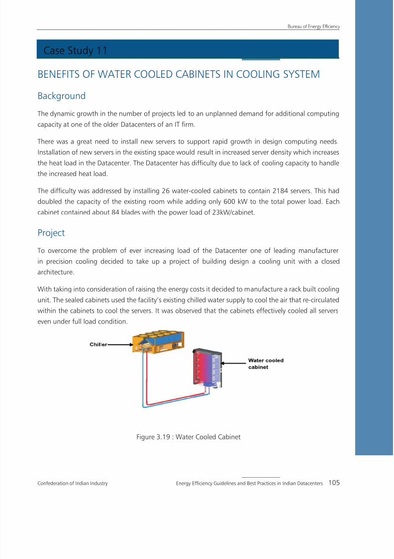
8/12/2019 CII & BEE Data Center Book
http://slidepdf.com/reader/full/cii-bee-data-center-book 125/250
Confederation of Indian Industry Energy Efficiency Guidelines and Best Practices in Indian Datacenters 105
Bureau of Energy Efficiency
Case Study 11
BENEFITS OF WATER COOLED CABINETS IN COOLING SYSTEM
BackgroundThe dynamic growth in the number of projects led to an unplanned demand for additional computing
capacity at one of the older Datacenters of an IT firm.
There was a great need to install new servers to support rapid growth in design computing needs.
Installation of new servers in the existing space would result in increased server density which increases
the heat load in the Datacenter. The Datacenter has difficulty due to lack of cooling capacity to handle
the increased heat load.
The difficulty was addressed by installing 26 water-cooled cabinets to contain 2184 servers. This had
doubled the capacity of the existing room while adding only 600 kW to the total power load. Each
cabinet contained about 84 blades with the power load of 23kW/cabinet.
Project
To overcome the problem of ever increasing load of the Datacenter one of leading manufacturer
in precision cooling decided to take up a project of building design a cooling unit with a closed
architecture.
With taking into consideration of raising the energy costs it decided to manufacture a rack built cooling
unit. The sealed cabinets used the facility’s existing chilled water supply to cool the air that re-circulated
within the cabinets to cool the servers. It was observed that the cabinets effectively cooled all servers
even under full load condition.
Figure 3.19 : Water Cooled Cabinet
8/12/2019 CII & BEE Data Center Book
http://slidepdf.com/reader/full/cii-bee-data-center-book 126/250
Bureau of Energy Efficiency
106 Energy Efficiency Guidelines and Best Practices in Indian Datacenters Confederation of Indian Industry
Advantages of closed server cabinet
Maximum energy efficiency=
Minimal air circulation=
Short air flow path=
Highest delta T / air return temperature=
Highest coolant feed / return temperature=
No dehumidification=
After observing the satisfactory operation, the water-cooled cabinet systems were installed in a
5000 sqft server room. Chilled water was supplied to the cabinets using pipes beneath the raised floor.
The room already contained about 2000 servers in conventional air-cooled racks, but there was enough
space to accommodate additional cabinets.
Totally 26 water-cooled cabinets were installed. Each cabinet contained 6 blade chassis with up to
14 blades per chassis for a total of up to 84 blades per cabinet. This created an average load of
approximately 21 kW per cabinet. Additional 2184 servers were added in water-cooled cabinets. This
increased the total number of servers in the room to more than 4000, which is double the previous
number of servers.
The sealed, water-cooled cabinets produced very little external heat up to 1 kW per cabinet. Therefore,
their effect on the room’s ambient air temperature was found to be negligible. However, the cabinets
placed an increased load on the Datacenter chilled water system, requiring the installation of additional
chillers and piping.
Benefits of the projectUsing water-cooled cabinets, which provide highly power-efficient cooling, it was able to quickly add
server capacity in the existing space to support business requirement.Water cooled cabinets can be
useful for increasing capacity of older Datacenters.
Useful for high density cooling solutions=
Removes heat at source and reduces load on CRAC units=
Modular and flexible system that can be expanded=
Flexible hose connectors and under floor manifold allows reconfiguration of racks in the future=
Increased compute power capacity up to 8X compared to air cooled facilities=
Can be retrofitted for existing installation=
ConstraintsWater-cooled cabinets are more expensive than air-cooled cabinets=
They introduce complexity, requiring additional monitoring=

8/12/2019 CII & BEE Data Center Book
http://slidepdf.com/reader/full/cii-bee-data-center-book 127/250
Confederation of Indian Industry Energy Efficiency Guidelines and Best Practices in Indian Datacenters 107
Bureau of Energy Efficiency
Case Study 12
OPERATE IT EQUIPMENT COOLING SYSTEM AT A HIGHERTEMPERATURE DIFFERENCE
Background
The heat load in the Datacenter is on constantly on the rise. Thermal management is often overburdened
with trying to effectively removing the heat load. However, structural conditions often mean that a
change over to a water-cooling system implementation cannot be immediate.
Thermal management equipment is often working at its full capacity, and consequently consume
enormous amount of energy.
ProjectOne of the leading manufacturers of the precision cooling units came up with cost effective option to
constantly separate the cold air zone from the warm air zone.
The cold air containment ensures that the cold air flowing through the raised floor is channeled through
the cabinets. As a result the all installed servers are provided with consistent cold air over the entire
height of the cabinet.
Figure 3.20: Typical arrangement of cold aisle containment

8/12/2019 CII & BEE Data Center Book
http://slidepdf.com/reader/full/cii-bee-data-center-book 128/250

8/12/2019 CII & BEE Data Center Book
http://slidepdf.com/reader/full/cii-bee-data-center-book 129/250
Confederation of Indian Industry Energy Efficiency Guidelines and Best Practices in Indian Datacenters 109
Bureau of Energy Efficiency
Case Study 13
CFD SIMULATION FOR ENHANCED DATACENTER PRODUCTIVITY
BackgroundHigh power dissipation from microprocessors, support chips, memory chips and mass storage has
resulted in large overall power dissipation from computer systems. The deployment of these computer
systems in large numbers and in very dense configurations in a Datacenter has resulted in very high
power densities at room level. These computer systems are deployed in a rack
Simulation Can Help Improve Reliability Visualization of airflow patterns and temperature distribution
and can help answer questions regarding
Plenum airflow patterns=
Room airflow patterns=
Rack inlet temperatures=
Static pressure distribution=
Tile airflow distribution=
Short-circuiting of airflow or re-circulation from rack outlets to rack inlets=
Effects of equipment and layout changes=
Effects of various failure scenarios=
The various ways in which simulation can be done are:
PAC Performance Analysis=
Floor Grill Analysis=
Rack Analysis=
PAC performance analysis:
Figure 3.21: PAC performance analysis

8/12/2019 CII & BEE Data Center Book
http://slidepdf.com/reader/full/cii-bee-data-center-book 130/250
Bureau of Energy Efficiency
110 Energy Efficiency Guidelines and Best Practices in Indian Datacenters Confederation of Indian Industry
Floor grill analysis:
Rack analysis
Figure 3.23: Rack analysis
Conclusion:Using CFD simulation, Facility Managers, IT Professionals, Designers, and Engineers can answer the=
question of whether or not the thermal environment for the equipment in their Datacenter (existing
or future) is acceptable
If conditions are unacceptable, then information about airflow patterns and temperature distributions=
in their Datacenter can be used by them to modify Datacenter layout (rack locations, tile locations)
and possibly adjust cooling equipment specifications/requirements
Process of simulation, evaluation, and Datacenter modification can be used to help ensure the=
reliability of the Datacenter
BenefitsCFDs help in simulating an environment which will enable the Datacenter operators to test the=
proposed Datacenter in various conditions
The CFD analysis requires external expertise=
Figure 3.22: Floor Grill analysis

8/12/2019 CII & BEE Data Center Book
http://slidepdf.com/reader/full/cii-bee-data-center-book 131/250

8/12/2019 CII & BEE Data Center Book
http://slidepdf.com/reader/full/cii-bee-data-center-book 132/250
Bureau of Energy Efficiency
112 Energy Efficiency Guidelines and Best Practices in Indian Datacenters Confederation of Indian Industry
During normal operation, the thermal storage tank valves are closed, isolating the 60 C water in the
tanks from the main 130 C chilled water system.
In the event of power outage, the centrifugal chillers stop. The thermal storage tank valves open and
add the water kept at 60 C to the main 130 C supply feeder line, helping to keep the main chiller water
supply at the required temperature limit.
Project details
A thermal storage system has been installed at the Datacenter facility of a leading company The facility
uses both centrifugal and scroll chillers. The three 1200 TR centrifugal chillers, which are more efficient
in terms of kW/TR, supply the main cooling system with chilled water at 130 C. This is used for sensible
cooling of the areas housing IT equipment and power supplies. There are two small 175 TR scroll chillers
to supply a smaller capacity system with chilled water at 6 0 C. This is used for latent cooling and non
critical loads. The 60 C system also cools the water in the thermal reserve tanks.
During a utility power outage, the chiller plant shuts down and takes several minutes to resume normal
cooling. The UPS continues to power the IT equipment in the Datacenter, which therefore continue
producing heat. Under such conditions, the servers in the Datacenter will suffer thermal damage and
shut down due to a high ambient temperature. Sometimes it may damage the servers and incur a
potentially huge cost for server replacement.
The solution was to install a large supplemental thermal reserve system. The system was based on two
100 m3 cold water tanks. The tanks were sized to provide enough capacity to cool the Datacenter for
7 minutes longer than the UPS battery life.
The chilled water pumps were on a separate facility. Therefore, they kept the cold water moving through
CRAH cooling coils. The CRAH fans were also on the UPS, so they continued to move air through the
cooling coils and deliver cold air to the Datacenter space.
Benefits of the project
The Thermal storage system enabled cooling operations to continue uninterrupted so as to facilitate
continuous IT process operations even during power outages.
The thermal storage system would find replication in scenarios where the ITprocess involves mission critical applications
The project involves major revamp of the cooling infrastructure, which requires
external expertise. The project, being highly capital intensive, has to be taken up as
part of a business decision

8/12/2019 CII & BEE Data Center Book
http://slidepdf.com/reader/full/cii-bee-data-center-book 133/250
Chapter 4
IT Equipment and Peripherals

8/12/2019 CII & BEE Data Center Book
http://slidepdf.com/reader/full/cii-bee-data-center-book 134/250
Bureau of Energy Efficiency
114 Energy Efficiency Guidelines and Best Practices in Indian Datacenters Confederation of Indian Industry

8/12/2019 CII & BEE Data Center Book
http://slidepdf.com/reader/full/cii-bee-data-center-book 135/250
Confederation of Indian Industry Energy Efficiency Guidelines and Best Practices in Indian Datacenters 115
Bureau of Energy Efficiency
Summary Note
on
'DATA CENTRE IT EQUIPMENTS AND PERIPHERALS'
Every datacenter has to respond to changes in density, capacity and availability created by new
technologies and changing business conditions. There is also an continuously growing need
for greater operating flexibility, higher system availability and lower operating costs. On top of
all this energy efficiency has emerged as one of top concerns for datacenters given the rising
cost and scarcity of energy. Therefore, it is essential to enhance the efficiency by choosing high-
efficiency equipment by design but this is often overlooked due to its high initial cost. However,
considering Total Cost of Ownership (TCO) provides a better way of focusing on high efficiency
designs. The options available to data center designers are very varied. Choice of designs and
equipment should be based on a careful analysis of current needs and projected growth based
on strong awareness of the advantages and disadvantages of each choice.
This initiative of CII under the guidance of BEE involving experts from the domain is an effort to
capture and thereby enable a higher degree of awareness about maximizing energy efficiency
of Data Centers through guidelines and key best practices documentation
This chapter on 'Data Centre IT Equipments & Peripherals' highlights some key points that help
in designing high efficiency datacenters like enterprise consolidation, network virtualization,
effective storage utilization, infrastructure efficiency improvement through virtualization etc.
I am extremely thankful to all members of this Group for their immense contribution towards
the successful completion of this Chapter. I would also like to appreciate how the members
managed to find time out of their busy schedules to attend the meetings and complete their
deliverables.
Last but the not the least, I would like to express my sincere thanks to Mr. Suprotim Ganguly and
Mr. D. Manikandan of CII for gathering experts from the domain and continuously driving the
effort forward through very effective co-ordination and organization of meetings and tracking
of deadlines.
Chandrashekhar AppannaChairman, Core Group on 'IT Equipments & Peripherals' &Distinguished Engineer, Cisco Systems Pvt Ltd

8/12/2019 CII & BEE Data Center Book
http://slidepdf.com/reader/full/cii-bee-data-center-book 136/250
Bureau of Energy Efficiency
116 Energy Efficiency Guidelines and Best Practices in Indian Datacenters Confederation of Indian Industry
LIST OF MEMBERS ON IT EQUIPMENT & PERIPHERALS (CORE GROUP - 3)
SI No Name Organization
1 Mr Chandrashekhar Appanna Cisco Systems India Pvt. Ltd.
2 Mr Anil Nileshwar Cisco Systems India Pvt. Ltd.
3 Mr K. Arun Bhat Intel Technology India Pvt. Ltd
4 Mr. Abhish Kulkarni Hewlett Packard India Sales Pvt. Ltd.
5 Mr Brahma Reddy Ctrl S Datacenters Ltd.
6 Dr Bhubhaneshwari Indian Institute of Technology, Delhi
7 Mr Girish S Jagajampi IBM India Pvt. Ltd.
8 Mr Kiran kumar Ctrl S Datacenters Ltd
9 Mr Kartik Ramarao Sun Microsystems India Pvt Ltd
10 Mr Ravi Giri Intel Technology India Pvt. Ltd
11 Mr Radhakrishna Infosys Technologies Ltd.
12 Mr Rishi Mehta Tata Communications Ltd.
13 Mr Sandeep Wattal IBM India Pvt. Ltd.
14 Mr Sringesh B S Wipro Infotech
15 Mr Sudeep Palanna Texas Instruments (India) Pvt. Ltd.
16 Mr Sudhir Nair Infosys Technologies Ltd.

8/12/2019 CII & BEE Data Center Book
http://slidepdf.com/reader/full/cii-bee-data-center-book 137/250
Confederation of Indian Industry Energy Efficiency Guidelines and Best Practices in Indian Datacenters 117
Bureau of Energy Efficiency
4.1 Introduction to server technology
A computer or electronic device serving out application or services can technically be called as
Server. A Server is a combination of hardware configured with specific program that delivers
services to its clients. Generally, server and client programs run on different computers which
transfer or exchange data over a communication network.
Traditionally, low power density servers using single core
micro-architecture processors were used in Datacenter
application. As demand for the service grow, the requirement
for operation of number of servers increased. In response to
such demand, the server market has witnessed noticeable
transition in the server technology.
For the reasons, such as power and space constraint,
IT infrastructure encounters difficulty with the use of
traditional low density servers.
The advancement in the server technology introduced
consolidation of multiple single core architecture
servers into a single multi-core architecture referred
as server blades. A blade server is a high-density
server, typically used in a clustering of servers that
are dedicated to a single/multi task. Like most
clustering applications, blade servers can also be managed to include load balancing and
failover capabilities. Each blade typically comes with one or two local ATA or SCSI Hard drives.For additional storage, blade servers can connect to a storage pool facilitated by a Network-
Attached Storage (NAS), Fiber Channel, or iSCSI Storage-Area Network (SAN). The advantage
of blade servers comes not only from the consolidation benefits of housing several servers in a
single chassis, but also from the consolidation of associated
resources like storage and networking equipment into a
smaller architecture that can be managed through a single
interface.
Servers are usually housed in operational/server rooms and
physical access to them is restricted for security reasons.They are often rack-mounted for convenience.
A server rack is a metal enclosure used in Datacenters and
server rooms to securely house all IT equipments. In addition
to servers, other IT networking and storage equipment is
also mounted in these racks. Racks are referred as server
racks, network enclosures, data racks, etc.
Due to power and space constraints,
IT infrastructure encounters
difficulty with the use of traditional
low density servers
Figure 4.1: Server Rack
Figure 4.2: Rack Enclousre

8/12/2019 CII & BEE Data Center Book
http://slidepdf.com/reader/full/cii-bee-data-center-book 138/250

8/12/2019 CII & BEE Data Center Book
http://slidepdf.com/reader/full/cii-bee-data-center-book 139/250
Confederation of Indian Industry Energy Efficiency Guidelines and Best Practices in Indian Datacenters 119
Bureau of Energy Efficiency
Studies show that 1 Watt saved at the server component level results in cumulative savings ofabout 2.84 Watts in total consumption, through cascade effect as shown in Figure 4.3. Thisflow of events is known as the Cascade Effect.
4.3 Challenges in Critical Cooling
IT equipment in a Datacenter generates a significant amount of heat. The heat has to be
removed properly to ensure the performance of the IT equipment. This is achieved by passingcold air through the server from the front and exhausting hot air at the rear end of theserver.
Advancements in server technology and the increase in the demand for higher computationalcapacity have strongly challenged the traditional air-conditioning system of a Datacenter. Asthe computational power increases, the power consumption of the servers also increases. It isevident from the fact that the rack power density had increased from 2kW/rack to
35-40kW/rack, creating hot zones in the Datacenter space. Therefore cooling system is oftenstretched to ensure proper cooling in all hot zones.
Latest cooling techniques adopt spot or supplemental cooling and In row cooling techniques
to address the hot zones in a Datacenter.
4.4 Strategies for reducing Datacenter energy consumption
A leading critical space management company cites the following 10 methods to minimizeDatacenter energy consumption. Let us consider a case of a 5000 sq. ft. Datacenter having120 W/Sq. ft. loading to calculate the savings.
The table 4.2 shows the statistical data of savings for the case considered on account ofimplementing various energy saving techniques.
Table 4.2: statistical data of savings
Strategy Initial datacenter Optimized datacenter Saving (KW) %
1 Low power processor 91W/processor (Average) 70W/processor 111 10%
30%
2 High-efficiency powersupplies
AC-DC79%DC-DC 85%
AC-DC90%DC-DC 88%
124 11%
3 Server powermanagement
Power consumption 80%of full load when idle
45% of full load when idle86 8%
4 Blade servers All rackmount 20% blades 7 1%
5 Server virtualization No virtualization 20% servers virtualized 86 8%
11%
6 Power distributionarchitecture
208V AC 415V AC provides 240V singlephase
20 2%
7 Implement coolingbest practices
Hot aisle/Cold aisle Optimized cold ais le and chilledwater temperature, no mixing ofhot and cold air
15 1%
8 Variable-capacitycooling
Fixed capacity cooling Variable capacity refrigeration andairflow
49 4%
11%9 High-density
supplemental coolingFloormount cooling only Floormount plus supplemental
cooling72 6%
10 Monitoring andoptimization
No coordination betweencooling units
Cooing units work as a team15 1%
Initial datacenter load: 1,127 kW Total savings 585 kW 50%+
Source : Emerson Network Power
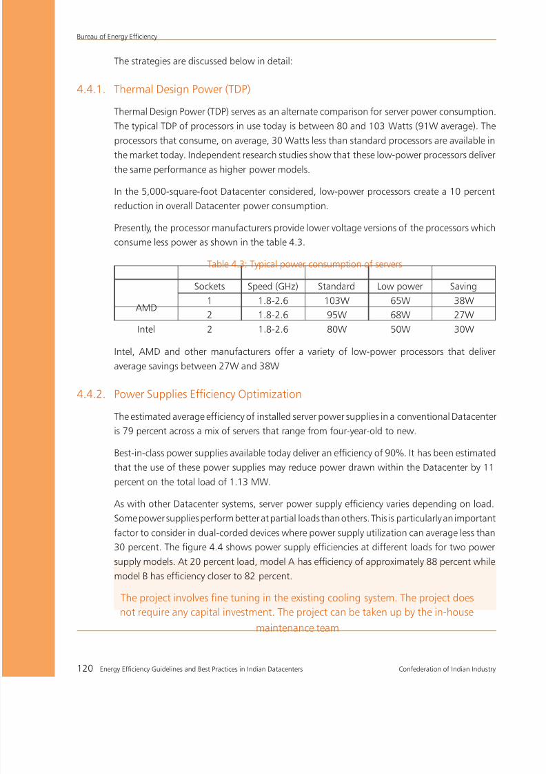
8/12/2019 CII & BEE Data Center Book
http://slidepdf.com/reader/full/cii-bee-data-center-book 140/250

8/12/2019 CII & BEE Data Center Book
http://slidepdf.com/reader/full/cii-bee-data-center-book 141/250
Confederation of Indian Industry Energy Efficiency Guidelines and Best Practices in Indian Datacenters 121
Bureau of Energy Efficiency
Figure 4.4: Percent of full load (vs) Efficiency of Power Supply
The figure 4.4 also highlights an opportunity to increase efficiency by sizing power supplies
closer to actual load. Notice that the maximum configuration is about 80 percent of the
nameplate rating and the typical configuration is 67 percent of the nameplate rating.
4.4.3. Utilizing Server Power Management Software (SPMS)
Datacenters are sized for peak conditions that may rarely exist. In a typical business Datacenter,
daily demand progressively increases from about 5 a.m. to 11 a.m. and begins to drop at 5
p.m.
Figure 4.5: Time (vs) Percent utilization of server

8/12/2019 CII & BEE Data Center Book
http://slidepdf.com/reader/full/cii-bee-data-center-book 142/250
Bureau of Energy Efficiency
122 Energy Efficiency Guidelines and Best Practices in Indian Datacenters Confederation of Indian Industry
Server power consumption remains relatively high as server load decreases. It is reported that
in the idle mode, most of the servers consume almost 70 to 85 percent of full operational
power.
80% of full load Power
during processor idle
condition
Increased Power consumptionwhen Processor on load
Figure 4.6: AC input power (vs) percent UPS time
Consequently, a facility operating at just 20 percent capacity may use 80 percent of the energy
that the same facility uses when operating at 100 percent capacity. Server processors have
power management features built-in that can reduce power when the processor is idle. Too
often these features are disabled because of concerns regarding response time; however, this
decision may need to be re-evaluated in the light of the significant savings that using this
technology can bring about with sacrificing the performance level.
With the power management enabled, the idle power
drawn reduces by 35% of the peak power.
In the given case, power management can save 8
percent of the overall Datacenter load.
4.4.4. High Density Server Blades (HDSB)
Blade servers are servers with a modular design used to minimize the number of conventional
servers and the physical space required to house them. A server blade is a complete server
(processor, system memory, network connection, and associated electronics, etc.) on a single
motherboard. The motherboard slides into a Blade enclosure. The enclosure can contain
multiple no of Blades as shown in Figure 4.7.
Server processors have built-
in power management features
that can reduce power during
processor idle condition

8/12/2019 CII & BEE Data Center Book
http://slidepdf.com/reader/full/cii-bee-data-center-book 143/250
Confederation of Indian Industry Energy Efficiency Guidelines and Best Practices in Indian Datacenters 123
Bureau of Energy Efficiency
Blade servers are suitable for specific purposes such as web
hosting and cluster computing. Blades are considered to be
hot-swappable, which means one can add new blades or
remove existing ones while the system is powered.
Many organizations have implemented blade servers to meet
processing requirements and improve server management.
While the move to blade servers is typically not driven by
energy considerations, blade servers can play a role in
energy conservation.
Blade servers consume about 10 percent less power than equivalent rack mount servers,
because multiple servers share common power supplies, cooling fans and other components.
More importantly, blades facilitate the move to a high-density Datacenter architecture, which
can significantly reduce energy consumption.
“High density architecture using Blade servers at least consume 10 percentless power than conventional servers for the same computational capacity”
4.4.5. Server Virtualization
Virtualization is being used to increase server
utilization and reduce the number of servers
required. It has been estimated and reporter that
8:1 virtualization may reduce the initial power
consumption by 12 to 20 percent.
4.4.6. Changing Power Distribution Architecture
The power distribution system represents another opportunity to reduce energy consumption;
however care must be taken to ensure the availability.
Many Datacenters use Double-Conversion type UPS. These systems convert incoming power toDC and then back to AC within the UPS. This enables the UPS to generate a clean, consistent
waveform for IT equipment and also effectively isolates IT equipment from the power source.
UPS systems that don’t convert the incoming power known as Line Interactive or passive
standby systems, may operate at higher efficiencies. This is because they do not undertake the
high-loss conversion process. However, these systems may compromise equipment protection
because they do not fully condition incoming power.
Figure 4.7: Blade server

8/12/2019 CII & BEE Data Center Book
http://slidepdf.com/reader/full/cii-bee-data-center-book 144/250
Bureau of Energy Efficiency
124 Energy Efficiency Guidelines and Best Practices in Indian Datacenters Confederation of Indian Industry
A bigger opportunity exists downstream from the UPS. In most of the Datacenters, the UPS
delivers power to the server at 208V. If the voltage can be raised to 240V, the power supplies in
the servers will operate at increased efficiency. Servers and other IT equipment can handle 240V
AC inputs without any negative consequences. Depending on the way the power distribution
is designed to deliver this higher AC voltage, energy savings can be as high as 2 percent of the
total energy consumption with the cascade effect and up to 3 percent taken in isolation.
4.4.7. Air management through Computational Fluid Dynamics (CFD) analysis
Many Datacenters have implemented hot-aisle/ cold aisle rack arrangement. Further potential
for increasing the cooling efficiency exists by sealing the gaps in floors, using blanking panels
in open spaces in racks, and avoiding the mixing of hot and cold air. The Computational
Fluid Dynamics (CFD) can be used to study the airflow pattern and suitable measures can be
taken to optimize the air flow to improve the cooling system efficiency. Many organizations
offer CFD study as part of Datacenter IT performance assessment services focusing on cooling
system efficiency improvement.CFD study as part of Datacenter assessment services focusingon cooling system efficiency improvement.
Figure 4.8: CFD Analysis
Additionally, optimizing the temperatures in the cold aisle may be a viable possibility to optimize
the cooling power consumption. When the required temperatures are above 68°F, the chilled
water temperature can be raised up to 50°F. In the case discussed, cooling system efficiency
was improved by 5 percent by adoption of these practices, improving energy efficiency by 1%
without any cost.
CFD analysis helps to study the
air fl ow pattern which facilitate
to formulate suitable measures
to improve the cooling system ef-
ficiency
When the required air temperatures is
above 68°F, optimization of chilled water
temperature from 45°F to 50°F has additional
energy saving to the tune of 2-3% in overall
energy consumption

8/12/2019 CII & BEE Data Center Book
http://slidepdf.com/reader/full/cii-bee-data-center-book 145/250
Confederation of Indian Industry Energy Efficiency Guidelines and Best Practices in Indian Datacenters 125
Bureau of Energy Efficiency
4.4.8. Variable-capacity cooling
Datacenter IT systems are sized to handle peak computational load which is a rare condition
and therefore the heat generation rate also changes. Consequently, indicated efficiency of the
cooling system at full load is often not the actual operating efficiency. Operating efficiency
would highly deviate from the design efficiency based on the loading.
Figure 4.9: Scroll Compressors
Latest technologies, such as Digital Scroll compressors and variable frequency drives in computer
room air conditioners (CRACs), maintains better operating efficiencies even at partial load
conditions. A digital scroll compressor dynamically regulates the capacity of air-conditioners
to match the room conditions without turning the compressors on and off.
Typically, CRAC fans run at a constant speed and deliver a constant volume of air flow.
Converting these fans to variable frequency drive fans allows fan-speed and power to bereduced as load decreases. Fan power draw is directly proportional to the cube of fan rpm
and 20 percent reduction in fan speed provides almost 50 percent of savings in fan power
consumption. These drives are available in retrofit kits that make it easy to upgrade existing
CRACs, with a payback period of less than one year as reported.
Figure 4.10: Temperature variation using Standard and digital scroll compressor

8/12/2019 CII & BEE Data Center Book
http://slidepdf.com/reader/full/cii-bee-data-center-book 146/250

8/12/2019 CII & BEE Data Center Book
http://slidepdf.com/reader/full/cii-bee-data-center-book 147/250
Confederation of Indian Industry Energy Efficiency Guidelines and Best Practices in Indian Datacenters 127
Bureau of Energy Efficiency
hot air generated by electronic equipment. The refrigerant is delivered to the supplemental
cooling modules through an overhead piping system. The overhead piping system provides
more flexibility and allows cooling modules to be easily added or relocated as the environment
changes.
A typical example of 20 racks at 12 kW density (Figure 4.12a) per rack use high-density
supplemental cooling while the remaining 40 racks (at 3.2 kW density) are supported by the
traditional room cooling system. This creates an incremental 6 percent reduction in overall
Datacenter energy costs.
Figure 4.12b: Schematic of supplemental cooling
4.4.10. Monitoring and Optimization
One of the consequences of rising equipment density has been increased diversity within
the Datacenter. Rack densities are rarely uniform across a facility and create hot zones in a
datacenter. Therefore, overall cooling system would operate in high cooling mode to maintain
adequate cooling in hot zones, which creates inefficiency in cooling system.
The implementation of adequate monitoring and proper optimization would suffice to
minimize the cooling system inefficiencies.
Figure 4.13: Schematic of CRAC unit with intelligent controller
One of the consequences of rising equipment density has been increased diversity within

8/12/2019 CII & BEE Data Center Book
http://slidepdf.com/reader/full/cii-bee-data-center-book 148/250
Bureau of Energy Efficiency
128 Energy Efficiency Guidelines and Best Practices in Indian Datacenters Confederation of Indian Industry
the Datacenter. Rack densities are rarely uniform across a facility and create hot zones in a
datacenter. Therefore, overall cooling system would operate in high cooling mode to maintain
adequate cooling in hot zones, which creates inefficiency in cooling system.
The implementation of adequate monitoring and proper optimization would suffice to
minimize the cooling system inefficiencies
4.5 Energy conservation tips for IT equipment
This section briefly discusses various energy saving possibilities in IT and IT Peripheral systems.
The following energy saving techniques are supported by the case studies given later in this
chapter.The following energy saving techniques are supported by the case studies given later
in this chapter.
4.5.1 Monitoring the utilization of servers, storage, and network devices
IT devices are designed based on the prediction of resource requirement in the present as well
as in the near future.
The capacity utilization of IT devices depends on the diversity factor, which is based on its
operation. Since the devices consume almost constant power at all conditions, IT systems are
under-utilized which leads to poor operational efficiency.
Continuous monitoring of utilization rates would facilitate Datacenter personnel with sufficient
data to plan necessary action for optimizing the performance of IT devices.
4.5.2 Server consolidation
Datacenters consist of various types of servers
based on application. The utilization rate of
the servers depends on the criticality of their
operation or mission of the Datacenter. A low
utilization rate of servers results in poor energy
performance.
The performance of a Datacenter can
be improved by server consolidation &
virtualization technology combined with
capacity fine-tuning of utilities (HVAC and
power).
Figure 4.14: CPU utilization (vs) fraction of time
The key causes of poor energy performance in Datacenters are:
Utilization of servers at a fraction of their processing capability
Over-sizing the data storage system and its infrequent access
Low data transfer rates in communication network
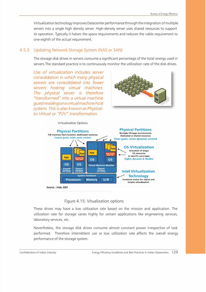
8/12/2019 CII & BEE Data Center Book
http://slidepdf.com/reader/full/cii-bee-data-center-book 149/250
Confederation of Indian Industry Energy Efficiency Guidelines and Best Practices in Indian Datacenters 129
Bureau of Energy Efficiency
Virtualization technology improves Datacenter performance through the integration of multiple
servers into a single high density server. High-density server uses shared resources to support
its operation. Typically it halves the space requirements and reduces the cable requirement to
one-eighth of the actual requirement.
4.5.3 Updating Network Storage System (NAS or SAN)The storage disk drives in servers consume a significant percentage of the total energy used in
servers.The standard practice is to continuously monitor the utilization rate of the disk drives.
These drives may have a low utilization rate based on the mission and application. The
utilization rate for storage varies highly for certain applications like engineering services,
laboratory services, etc.
Nevertheless, the storage disk drives consume almost constant power irrespective of task
performed. Therefore intermittent use or low utilization rate affects the overall energy
performance of the storage system.
Use of virtualization includes serverconsolidation in which many physical
servers are consolidated into fewer servers hosting virtual machines.The physical server is therefore“transformed” into a virtual machine
guest residing on a virtual machine host system. This is also known as Physical-to-Virtual or “P2V” transformation.
Figure 4.15: Vitualization options

8/12/2019 CII & BEE Data Center Book
http://slidepdf.com/reader/full/cii-bee-data-center-book 150/250
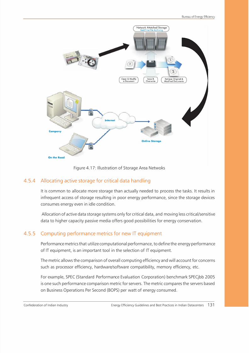
8/12/2019 CII & BEE Data Center Book
http://slidepdf.com/reader/full/cii-bee-data-center-book 151/250
Confederation of Indian Industry Energy Efficiency Guidelines and Best Practices in Indian Datacenters 131
Bureau of Energy Efficiency
Figure 4.17: Illustration of Storage Area Netwoks
4.5.4 Allocating active storage for critical data handling
It is common to allocate more storage than actually needed to process the tasks. It results in
infrequent access of storage resulting in poor energy performance, since the storage devices
consumes energy even in idle condition.
Allocation of active data storage systems only for critical data, and moving less critical/sensitive
data to higher capacity passive media offers good possibilities for energy conservation.
4.5.5 Computing performance metrics for new IT equipment
Performance metrics that utilize computational performance, to define the energy performance
of IT equipment, is an important tool in the selection of IT equipment.
The metric allows the comparison of overall computing efficiency and will account for concerns
such as processor efficiency, hardware/software compatibility, memory efficiency, etc.
For example, SPEC (Standard Performance Evaluation Corporation) benchmark SPECjbb 2005
is one such performance comparison metric for servers. The metric compares the servers based
on Business Operations Per Second (BOPS) per watt of energy consumed.

8/12/2019 CII & BEE Data Center Book
http://slidepdf.com/reader/full/cii-bee-data-center-book 152/250
Bureau of Energy Efficiency
132 Energy Efficiency Guidelines and Best Practices in Indian Datacenters Confederation of Indian Industry
The typical comparison chart for few servers is shown in chart.
Source : SPECjbb2005
Figure 4.18: Performance comparison of different processors
SPECjbb2005 (Java Server Benchmark) is SPEC’s benchmark for evaluating the performance of
server side Java. Like its predecessor, SPECjbb2000, SPECjbb2005 evaluates the performance
of server side Java by emulating a three-tier client/server system (with emphasis on the middle
tier). The benchmark exercises the implementations of the JVM (Java Virtual Machine),
JIT (Just-In-Time) compiler, garbage collection, threads and some aspects of the operating
system. It also measures the performance of CPUs, caches, memory hierarchy and the scalability
of shared memory processors (SMPs). SPECjbb2005 provides a new enhanced workload,
implemented in a more object-oriented manner to reflect how real-world applications are
designed and introduces new features such as XML processing and Big Decimal computations
to make the benchmark a more realistic reflection of today’s applications.
SPECjbb2005 Benchmark Highlights
Emulates a 3-tier system, the most common type of server-side Java application today.=
Business logic and object manipulation, the work of the middle tier, predominate.=
Clients are replaced by driver threads, database storage by binary trees of objects.=
Increasing amounts of workload are applied, providing a graphical view of scalability.=
The architecture schematic of the SPEC jbb2005 benchmark process is given below:

8/12/2019 CII & BEE Data Center Book
http://slidepdf.com/reader/full/cii-bee-data-center-book 153/250
Confederation of Indian Industry Energy Efficiency Guidelines and Best Practices in Indian Datacenters 133
Bureau of Energy Efficiency
Figure 4.19: Benchmark Process
4.5.6 Virtualization of Network Devices
Network virtualization technologies enable increased utilization of network resources and exert
more control over allocation of resources, adding more operational flexibility and scalability
of resources.
It also reduces the cost and complexity of managing network infrastructure by reducing the
number of physical devices in the network.

8/12/2019 CII & BEE Data Center Book
http://slidepdf.com/reader/full/cii-bee-data-center-book 154/250
Bureau of Energy Efficiency
134 Energy Efficiency Guidelines and Best Practices in Indian Datacenters Confederation of Indian Industry
Case of Study 15
BENEFITS OF ACCELERATED SERVER REFRESH STRATEGY
The project involves design computing server refresh strategy that takes advantage of increasing server
performance and energy efficiency to reduce the operational cost of Datacenters.
Same performance delivered for 90% less power and space
Background
The Server is one of the primary elements of a Datacenter. It provides specified service to the clients
connected to it. The power consumption of a server is largely determined by its computational capacity
of its processor.
Advancements in processor architecture have improved the computational performance to higher
levels. The performance of servers has improved drastically with the introduction of “Multiple Core”
architecture based processors. These processors support parallel processing and multi-threading
techniques, thus enabling the simultaneous processing of multiple programs resulting in high density
computational systems.
The use of high density computational servers enables
consolidation of conventional servers and reduces
the consumption of resources such as power, space,
power supply units, and the cooling system.
The consolidation ratio is based on processor
performance and the type of application being
processed. The latest servers have a high consolidation
ratio thus reducing the need for an expansion of
facilities and avoiding construction costs even for
increased computational capacity requirements.
Project details
The case is an initiative of a leading semiconductor design company which has increasing complex
design computing requirements. The number of design computing servers had increased from 1000
in 1996 to 68000 in 2007. With the increasing computational requirements, the company faced the
challenge of accommodating additional number of servers within the existing space, cooling and power
infrastructure.
Benefits of the project
Reduction of 850-890 kWh in energy=
Consumption by consolidation of every
500 older servers using blade server
Same performance delivered for 90% less=
power and space
Improved performance increases the=
productivity in design environment

8/12/2019 CII & BEE Data Center Book
http://slidepdf.com/reader/full/cii-bee-data-center-book 155/250
Confederation of Indian Industry Energy Efficiency Guidelines and Best Practices in Indian Datacenters 135
Bureau of Energy Efficiency
It becomes extremely expensive to build a new Datacenter and also to maintain and operate the growing
population of conventional low-efficiency servers.
To tackle this problem, the company initiated an enterprise-wide Datacenter energy management
program to explore the alternative server refresh strategy that takes advantage of increased server
performance which optimizes the infrastructure usage and reduces the operational costs.
The company performed an extensive analysis to determine the benefits of accelerated server refreshes.
The company analyzed the ROl that could be obtained by adopting different refresh cadences, ranging
from one to six years. For example, with a six-year cadence, the company had consolidated and replaced
all design servers more than six years old.
Figure 4.20: Refresh Cadence evaluation
The analysis estimated total costs over eight years with an assumption that the cost of each new server
would remain stable over this evaluation period and the computing requirements would continue to
increase at 15 percent per year. The analysis also accounted for region-wise cost variation in construction
and utilities. Software cost was not included as it had already been considered as part of their broader
Datacenter efficiency program.
The company found that a four-year refresh cycle delivered the highest ROI.

8/12/2019 CII & BEE Data Center Book
http://slidepdf.com/reader/full/cii-bee-data-center-book 156/250
Bureau of Energy Efficiency
136 Energy Efficiency Guidelines and Best Practices in Indian Datacenters Confederation of Indian Industry
Results of the project
Based on the high consolidation ratios that can be achieved in batch computing platform in a design
environment, the estimated reduction in energy consumption was approximately 850-890 kWh by
consolidation of 500 old severs using blade servers.
The program projected an increase in computational capacity for same the space and utilities. The
performance of the new servers also boosted productivity across the design services.
With the four-year refresh cycle program, the company saved nearly Rs 12500 million due to the best
combination of construction avoidance, and utilities savings after accounting for server refresh costs

8/12/2019 CII & BEE Data Center Book
http://slidepdf.com/reader/full/cii-bee-data-center-book 157/250
Confederation of Indian Industry Energy Efficiency Guidelines and Best Practices in Indian Datacenters 137
Bureau of Energy Efficiency
Case Study 16
ENTERPRISE COMPUTING PERFORMANCE IMPROVEMENTTHROUGH CONSOLIDATION OF DATACENTERS
The project demonstrates the adoption of high density computing equipment for consolidation of
Datacenters at various sites, thereby improving the computational performance of an enterprise.
Background
The case is the success story of a leading technology developer who supplies technology solutions to
critical business market. The company owns many laboratories and facilities for its R&D services and
production. The laboratories have exclusive Datacenters catering to their testing requirements.
The consolidation of the laboratories from various locations and the expansion in the operations poseda challenge to the existing conventional servers, both in performance as well as increased demand for
infrastructure such as space, power and cooling. To meet the increasing growth, additional infrastructure
was required.
In addition, the company had to compete with the power outages that impact the availability and
performance of its R&D applications. The company recognized the need for newer, high-density
equipment that would occupy less space and consume less power.
Project details
The company used a combination of its own
technology, and advanced power and cooling
systems to operate a state-of-the-art laboratory
Datacenter in Bangalore. The Datacenter surmounts
obstacles related to high electric power consumption and sets high standards for eco-responsible
computing and overall operational efficiency.
The organization initiated the consolidation project, applying Datacenter design models, and services
such as custom consolidation architecture, design and migration services(CADMS), etc. It had proved
their ability to reduce operating costs and improve performance and availability at facilities worldwide.
The consolidation resulted in migration of applications from approximately 300 older servers to 100
new higher servers.
The new high density servers presented a challenge to the conventional low density design of the
cooling-system. The Datacenter design utilized a hot aisle containment technique based on Row
Cooling (RC). The RC devices trap and neutralize the heat generated by the equipment to eliminate the
Benefits of the project17% reduction in power Consumption and=
15% reduction in Space Requirements
154% Increase in Computing Capacity=

8/12/2019 CII & BEE Data Center Book
http://slidepdf.com/reader/full/cii-bee-data-center-book 158/250
Bureau of Energy Efficiency
138 Energy Efficiency Guidelines and Best Practices in Indian Datacenters Confederation of Indian Industry
mixing of hot and cold air in the room.The units sense the temperatures and speed up or slow down the
cooling fans as required, making for a very efficient solution. The Datacenter used standard racks that
provide a consistent footprint for all users and allow space-saving dense cable configuration.
Results of the project
The consolidation has increased the computational capacity by 154% while reducing electric power
consumption by 17%. While helping to reduce costs and power consumption, the new Datacenter
design has also boosted productivity across the R&D services.
Cumulative Net Benefit (Values in Million)
0.12
0.94
1.76
2.58
3.41
Y ear 1 Y ear 2 Y ear 3 Y ear 4 Y ear 5
Figure 4.21: Cumulative Net benefit
The consolidation also offered more tools to engineers, with greater availability, better performance,
and consistent resource for access.
The project resulted in cumulative five-year savings of Rs 3.4 million with the investment of Rs 0.93
million.
Cost benefit analysis
Cumulative five-year savings - Rs 34 Lakhs
Investment - Rs 9.25 Lakhs
Payback Period - 10 months
Annual ROI - 74%

8/12/2019 CII & BEE Data Center Book
http://slidepdf.com/reader/full/cii-bee-data-center-book 159/250
Confederation of Indian Industry Energy Efficiency Guidelines and Best Practices in Indian Datacenters 139
Bureau of Energy Efficiency
Case Study 17
NETWORK VIRTUALISATION FOR PERFORMANCE IMPROVEMENT
The project discusses virtualization of campus wide networks for reducing complexity, increasing
availability, manageability, security, scalability, and energy performance of the network.
Background
Data communication is one of major areas in IT business. A network is the integration of various IT
and data transfer equipment to enable data process and secure data transfer. It is an integral part of IT
operations.
Increasing business demand causes network to grow as a complex system. This increases the need for
scalable solutions to segregate group of network users and their resource.
The increase in network size poses challenge to data security, access control, resource/service sharing,
scalability, and energy performance.
Virtualization of a large network minimizes the operational complexity and improves data security.
Network virtualization enables a single physical device or resource to act like multiple physical resource
shared by the network.
Virtualization increases the utilization of network resource such as servers and storage-area networks
(SANs). Various techniques such as centralized policy management, load balancing, dynamic allocation
and virtual firewalls enhances network agility by improving efficiency and optimizing resource thereby
reducing both capital and operational expense.
Also, the use of Layer-3 technologies such as GRE (Generic Routing Encapsulation) Tunnels and MPLS
VPN enables a simple and effective approach to create closed user groups on a large campus wide
network.
Authentication and Access-Layer Security is used for access control to mitigate threats at the edge and
remove harmful traffic before it reaches the distribution or core layer.
Challenges faced
Access control: To ensure the recognition of legitimate users and devices and to classify and authorize
to access the assigned portion of the network
Path isolation: To ensure the mapping of substantiated user or device to their available resources
effectively; the right VPN (Virtual Private Network)
Services edge: To ensure the accessibility of services to the legitimate users and devices by centralized
policy enforcement

8/12/2019 CII & BEE Data Center Book
http://slidepdf.com/reader/full/cii-bee-data-center-book 160/250

8/12/2019 CII & BEE Data Center Book
http://slidepdf.com/reader/full/cii-bee-data-center-book 161/250
Confederation of Indian Industry Energy Efficiency Guidelines and Best Practices in Indian Datacenters 141
Bureau of Energy Efficiency
Case Study 18
EFFECTIVE STORAGE UTILIZATION OPTIMIZES DATACENTEROPERATIONAL COST
The project discusses the methods to improve the storage utilization rate and to reduce the operational
cost in storage system.
Background
The company has a large, rapidly growing, and increasingly complex storage environment. Business
growth drives increased enterprise transactions and usage of applications which had resulted in the
expansion of storage system.
A study showed that a significant amount of capacity growth resulted from various factors such as
under-utilizing existing capacity, storing duplicate copies of existing data, and retaining data that is no
longer required.
At the end of 2007, the company managed 20 petabytes of primary and backup storage infrastructure
constituting 7 percent of its Total Cost of Ownership (TCO), with storage capacity growing at
35 to 40 percent per year. It is the rate that would have lead to 90 petabytes of storage capacity by
2012 and also would have doubled the storage operational cost.
Key issues faced
The company has experienced difficulties in the following areas:
Demand forecasting
There was no specified requirement from the client/user or any effective tool or method for
forecasting
Capacity management
Inadequate reporting on storage capacity and its performance led to inef¬ficiencies in planning,
provisioning, tiering and purchasing. Here again, inadequacy or nonexistent of tools made it difficult to
forecast and maintain optimal storage capacity
Alignment between data value and storage technologies
Current method and tool limits the operations group’s ability to effectively classify the data based on
its business value and match it to appropriate storage infrastructure. This led to over-provisioning of
storage services resulting in higher operational expenses

8/12/2019 CII & BEE Data Center Book
http://slidepdf.com/reader/full/cii-bee-data-center-book 162/250
Bureau of Energy Efficiency
142 Energy Efficiency Guidelines and Best Practices in Indian Datacenters Confederation of Indian Industry
Archive and purge policies
The default meth¬odology was to retain all the data irrespective of its business value with few broad
policies or enforcement regarding reten-tion and deletion of data. Data with little or no value was often
retained indefinitely in costly primary- storage infrastructure, with multiple copies for operational and
disaster recovery purposes.
Project details
The company adopted three key strategies for storage optimization.
Strategy-1: Virtualization, Tiering, and Application Alignment
Virtualization of storage enabled multiple systems to share and access a single storage device. The
storage infrastructure included both SAN and NAS environments.
Virtualized storage environments enable tiered storage and transfers data amongst virtual storagemachines with relative ease.
Tiering and application alignment had impact on performance by increasing utiliza¬tion and scalability,
enabling multi-vendor sourcing, and simplifying management. Tiering strategies reduced overall
ownership cost of the storage.
Storage-Medium Allocation improvement was done through NAS/SAN virtualization, system-to-
application mapping and alignment, and data migration
Strategy-2: Capacity Management
Capacity management had improved the utilization rate of storage devices by implementation of various
techniques such as thin provisioning, fabric unification, storage reclamation and capacity management
reports and metrics.
Strategy-3: Data Management
Data management technologies reduced the volume of data to be stored and restricted the capacity
growth through various techniques like writable snapshots, de-duplication, Next-generation (D2D)
backup and recovery, etc.
Benefits of the project
The estimated TCO in the full-potential scenario would just be 13 percent higher in 2014 than in 2007,
while the estimated baseline TCO would experience a 279 percent increase in the same period. These
numbers are a strong confirmation of the benefits of a holistic approach to storage optimization, and
are reinforced by equally impressive results in controlling power consumption.

8/12/2019 CII & BEE Data Center Book
http://slidepdf.com/reader/full/cii-bee-data-center-book 163/250
Confederation of Indian Industry Energy Efficiency Guidelines and Best Practices in Indian Datacenters 143
Bureau of Energy Efficiency
Table 4.4: Benefits of the project
PerformanceIndicator
2007 ActualValues
Baseline 2012End Point
Optimized2012 End
Point
Baseline 2014End Point
Optimized2014 End
Point
Total capacity
(petabytes) 20 90 66 165 95
Powerconsumed(kWh/year)
18.0M 39.4M 29.1M 65.6M 34.9M
Required FTEheadcount
95 140 90 166 90
TCO run rate 100% 200% 103% 279% 113%
Figure 4.22: Storage TCO (Source : Intel)
The project has a high replication potential where the storage cost is a significant
part of the company’s total operational cost
The project involves major revamp of the storage infrastructure requiring external
expertise. The project, being capital intensive, has to be taken up as part of a
business decision

8/12/2019 CII & BEE Data Center Book
http://slidepdf.com/reader/full/cii-bee-data-center-book 164/250
Bureau of Energy Efficiency
144 Energy Efficiency Guidelines and Best Practices in Indian Datacenters Confederation of Indian Industry
Figure 4.23 : Datacenter Infrastucture Effciency (Source : APC)
Case Study 19
INFRASTRUCTURE EFFICIENCY IMPROVEMENT IN A VIRTUALIZEDENVIRONMENT
Background
Virtualization of servers reduces server population and power and cooling requirements. Thus it results
in reduced IT power consumption and overall Datacenter power consumption. The key characteristic of
virtualization is the high density operation of servers. It also introduces new operational challenges into
the Datacenter environment.
Key challenges in a virtualized environment:
Increased server criticality
Virtualization brings higher and higher processor utilization, increasing the business importance of each
physical server, thus making effective power and cooling even more critical in maintaining availability.

8/12/2019 CII & BEE Data Center Book
http://slidepdf.com/reader/full/cii-bee-data-center-book 165/250
Confederation of Indian Industry Energy Efficiency Guidelines and Best Practices in Indian Datacenters 145
Bureau of Energy Efficiency
Dynamic and migrating high-density loads
With virtualization, applications can be dynamically started and stopped, resulting in loads that change
both over time AND in physical location. This adds a new challenge to the architecture and management
of power and cooling
Under-loading of power and cooling systems
If power and cooling capacity is not optimized to the new lower IT load, Datacenter infrastructure
efficiency (DCiE) will go down after virtualization. Therefore calling down of infrastructure to match the
IT load further reduces the power consumption in the Datacenter.
Dynamic and migrating high-density loads
Virtualization enables dynamic load allocation to servers, and high processor utilization capability,
inducing localized high-density hot zones in the Datacenter.
The dynamic loading of servers results in a shifting of the thermal profile of the room with no visible
physical changes in equipment. The schematic condition is shown in figure 4.24.
Figure 4.24 : Migration of load over a period of time in a virtualized environment (Source : APC)
Under such conditions, the conventional room based cooling technique sometimes becomes ineffective
even with a cooling capacity of more than 2 times the actual required capacity.
Rack based cooling or targeted cooling located close to the load act as a supplement and provides
an effective solution for efficiently removing the high density heat load. The figure 4.25 shows theschematic of row/rack based cooling system.

8/12/2019 CII & BEE Data Center Book
http://slidepdf.com/reader/full/cii-bee-data-center-book 166/250

8/12/2019 CII & BEE Data Center Book
http://slidepdf.com/reader/full/cii-bee-data-center-book 167/250
Confederation of Indian Industry Energy Efficiency Guidelines and Best Practices in Indian Datacenters 147
Bureau of Energy Efficiency
As load increases, the device’s fixed loss stays the same, and other losses increase in proportion to the
amount of load. This is called proportional loss.
As load increases, fixed loss becomes a smaller and smaller percentage of the total energy used, and as
the load decreases, fixed loss becomes a larger percentage of the total energy used
Virtualization improves IT system energy performance and reduces the load on power and cooling
systems. The reduction in load further reduces the loading on the power and cooling equipment,
resulting in inefficient operation. Power and cooling devices that can scale down in capacity will reduce
the fixed losses proportionally and increase operating efficiency. Scalable architecture will not only
facilitate the downsizing of capacity which follows IT consolidation, but also subsequent growth by
following the expansion of the virtualized IT load as shown in figure 4.26.
Figure 4.26: Scalable Power and Cooling to Minimize the Inefficiency of
Unused Capacity during Consolidation and Growth (Source : APC)
Datacenter infrastructure efficiency (DCiE) will go down after virtualization, due to fixed losses in unused
power & cooling capacity. With optimized power and cooling to minimize unused capacity, power and
cooling efficiency (DCiE) can be brought back to nearly pre-virtualization levels – sometimes even better
ones, depending upon the nature of improvements in the cooling architecture.
Datacenter Efficiency as a Function of IT Load
Datacenter efficiency is always higher at high IT loads. Therefore Datacenter efficiency is a function of
IT load. A typical Datacenter infrastructure efficiency curve is shown in figure 4.27.
Every Datacenter will have a higher or lower infrastructure efficiency curve depending upon the efficiencyof its individual devices and the efficiency of its system configuration. The curve always starts at zero
and follow the shape shown in figure 4.27.

8/12/2019 CII & BEE Data Center Book
http://slidepdf.com/reader/full/cii-bee-data-center-book 168/250
Bureau of Energy Efficiency
148 Energy Efficiency Guidelines and Best Practices in Indian Datacenters Confederation of Indian Industry
Figure 4.27 : Typical Datacenter Infrastructure Efficiency Curve (Source : APC)
Virtualization will always reduce power consumption due to the optimization and consolidation of
computing devices. However, if no concurrent downsizing or efficiency improvement is done to power
and cooling infrastructure, the infrastructure efficiency (DCiE) will move down on the curve because of
the reduced IT load as shown in figure 4.28below.
Figure 4.28 : Consolidation Reduces Infrastructure Efficiency
if the Datacenter’s Infrastructure Remains Unchanged (Source : APC)
The Datacenter’s infrastructure efficiency curve must be raised by optimizing the power and cooling
systems to reduce the fixed loss and optimize the infrastructure capacity to the new IT load. Optimization
of infrastructure capacity would change the infrastructure efficiency curve and improve the post-
virtualization DCiE as shown in figure 4.29.

8/12/2019 CII & BEE Data Center Book
http://slidepdf.com/reader/full/cii-bee-data-center-book 169/250

8/12/2019 CII & BEE Data Center Book
http://slidepdf.com/reader/full/cii-bee-data-center-book 170/250

8/12/2019 CII & BEE Data Center Book
http://slidepdf.com/reader/full/cii-bee-data-center-book 171/250

8/12/2019 CII & BEE Data Center Book
http://slidepdf.com/reader/full/cii-bee-data-center-book 172/250
Bureau of Energy Efficiency
152 Energy Efficiency Guidelines and Best Practices in Indian Datacenters Confederation of Indian Industry

8/12/2019 CII & BEE Data Center Book
http://slidepdf.com/reader/full/cii-bee-data-center-book 173/250
Confederation of Indian Industry Energy Efficiency Guidelines and Best Practices in Indian Datacenters 153
Bureau of Energy Efficiency
Summary Note on
'Data Centre Operations and Maintenance'
The Operations and Maintenance of critical facilities like Datacenters is recognized as an
important tool for achieving operational excellence. Operational excellence translates into
reliable, safe, secure and efficient operations of all the business systems in a Datacenter. As
the robustness and associated complexity of critical infrastructures increase, the importance
of establishing robust Operations and Maintenance practices to manage these facilities
has become quite imperative. Once a Datacenter is designed and implemented, it becomes
the responsibility of the operations and maintenance team to operate, monitor, report and
maintain the infrastructure. Every site needs to define its key performance indices, and then
monitor, report and drive for improvement. This can be done through proper auditing, logging
and analysis of the key parameters.
It was therefore timely that the Confederation of Indian Industries (CII) under the guidance of
the Bureau of Energy Efficiency (BEE), Government of India, took up this exercise of developing
guidelines and best practices for Energy Efficiency in the Indian Datacenter. The exercise
involved all the stakeholders coming under the domain and was indeed a 'one-of-its-kind'
initiative.
This Chapter on 'Datacenter Operations and Maintenance' is the result of a collective effort
focusing typically on the Management Information Systems (MIS) format and has capturedthe benefits through metering and monitoring systems for effective energy management and
other related areas.
1 am extremely thankful to all the members of this Group for their immense contribution
towards the successful completion of this Chapter.
Sudeep PalannaChairman, Core Group on 'Operation and Maintenance' &
Facilities,Texas Instruments India Pvt Ltd

8/12/2019 CII & BEE Data Center Book
http://slidepdf.com/reader/full/cii-bee-data-center-book 174/250
Bureau of Energy Efficiency
154 Energy Efficiency Guidelines and Best Practices in Indian Datacenters Confederation of Indian Industry
LIST OF MEMBERS ON OPERATION & MAINTENANCE (CORE GROUP-4)
SI.No Name Organization
1 Mr Anand Vanchi Intel Technology India Pvt Ltd.
2 Mr Anand Chandra Mouli Infosys Technologies Ltd.
3 Mr Arun K. Bhat Intel Technology India Pvt Ltd.
4 Mr Bhanu Kumar Jain Spectral Services Consultant Pvt. Ltd.
5 Mr Karthikheyan DS Wipro Infotech
6 Mr Manu Kumar Hewlett Packard India Sales Pvt Ltd.
7 Mr Muthu Swamy MIC Electronics Ltd
8 Mr Rishi Mehta Tata Communications Ltd.
9 Mr. S Ramachandran Tata Consultancy Services
10 Mr Ravi Meghani Wipro Technologies
11 Mr Santhosh Srihari WiproTechnologies
12 Mr Shailesh C. Zarkar Iconic Designs Pvt. Ltd.
13 Mr Sharfoddin Mohammed WiproTechnologies
14 Mr T.S. Shankar Cisco Systems (India) Pvt. Ltd.
15 Mr. Sudhir Setty Intel Technology India Pvt Ltd.
16 Mr Sudeep Palanna Texas Instruments India Pvt Ltd.

8/12/2019 CII & BEE Data Center Book
http://slidepdf.com/reader/full/cii-bee-data-center-book 175/250

8/12/2019 CII & BEE Data Center Book
http://slidepdf.com/reader/full/cii-bee-data-center-book 176/250
Bureau of Energy Efficiency
156 Energy Efficiency Guidelines and Best Practices in Indian Datacenters Confederation of Indian Industry
The technical documentation shall comprise of the following:
Design intent with system description=
Completed and approved testing and commissioning forms=
Non conformation (NCR) items –Snag list completed and approved=
Reports on training completion details of the operating and maintenance personnel=
Equipment warranty information=
Operation and maintenance (O&M) manual customized to the installed system=
Standard O & M manual for all equipment=
As-build drawings (Both in soft and hard copy)=
Single-line diagrams /schematics of all systems (Mechanical, Electrical & Plumbing (MEP),=
Monitoring &Controls, Fire &safety) (soft and hard copies)
List of Spare parts and special tools to be used=
5.3 Manpower and Training
The need and importance of having a
well-defined and standardized operating
and maintenance system will go a long
way in the effective functioning of the
Datacenter.
The importance of having a properly defined and standardized operating and maintenance is a
well – acknowledged fact in an industry.
Besides the regular trainings on O&M procedures, it is recommended that the operator should
be sensitized to the energy and environmental impact of his or her actions. Lower energy and
operating costs can be realized when every individual realizes the necessity of their contribution
to the overall energy conservation.
5.4 Housekeeping
A site should have a defined and regular house
keeping program. Maintaining a clean and dust-
free environment has benefits in terms of better air
movement through CRAC units and IT equipment.
Better air movement ensures proper heat transfer
from the equipment and thus minimizes failures.
Adopting 5S methodology tools and techniques
would facilitate in maintaining a clean and dust-free
environment.
Technical training for Operation and
Maintenance personnel is imperative to
sustain the progress
Figure-5.1:5S Methodology

8/12/2019 CII & BEE Data Center Book
http://slidepdf.com/reader/full/cii-bee-data-center-book 177/250
Confederation of Indian Industry Energy Efficiency Guidelines and Best Practices in Indian Datacenters 157
Bureau of Energy Efficiency
The process of 5S is shown in figure 5.1. 5S methodology emphasizes self discipline, and
orderliness. It is recommended to adopt 5S practices to organize and maintain the datacenter.
Figure-5.1A : Standardising the administration
5.5 Preventive maintenance
In most of the facilities, the preventive maintenance is a routine task based on time interval
or frequency. The limitation however with the approach is that the tasks occur regardless of
actual operating condition and generally involve a shutdown of the equipment, which may be
difficult and not recommended in Datacenters.
Monitoring of metrics like Mean Time Between Failures (MTBF) can indicate the effectiveness
of a preventive maintenance program.
5.6 Breakdown maintenance
Breakdown maintenance refers to repairs carried out after equipment has failed. In a datacenter
environment, this could prove to be costly. Also, it is necessary to have a proper response
mechanism to failures and a proper root-cause analysis to prevent future reoccurrences of the
failure. Monitoring of indices like mean time between repairs is beneficial.
Source : Industry

8/12/2019 CII & BEE Data Center Book
http://slidepdf.com/reader/full/cii-bee-data-center-book 178/250
Bureau of Energy Efficiency
158 Energy Efficiency Guidelines and Best Practices in Indian Datacenters Confederation of Indian Industry
5.7 Condition based monitoring
Figure- 5.2: Transformer online monitoring system
Condition based monitoring refers to technologies that allow maintenance to take place based
on actual operating conditions. A simple example is using a differential pressure sensor to
monitor filter condition. When the filter loads up, the pressure drop (∆P) increases and the
filter is replaced when appropriate.
Condition-monitoring technologies can be used to track real-time data and predict the
necessary maintenance action required in advance. This is called predictive maintenance.
Thresholds can be assigned for alerts and alarm conditions, and by analyzing the trends,
one can predict the exceeding of thresholds and even failures. Figure 5.2 shows the online
monitoring of transformer.
Some examples of operating condition monitoring technologies include vibration analysis and infrared
thermal scans. These technologies are used to analyze the operating condition of the equipment while
the equipment is online, without requiring shutdowns or maintenance outages.
5.8 Capacity vs Utilization
Monitoring of capacity versus
utilization is very important as it provides
opportunities for improving the energy
efficiency levels in equipment. Continuous
monitoring of equipment and MIS data
facilitate IT managers to take action for improving energy efficiency by reducing energy loss in
CPU, storage, UPS, etc.
Higher capacity utilization improves
the operational efficiency levels in aDatacenter

8/12/2019 CII & BEE Data Center Book
http://slidepdf.com/reader/full/cii-bee-data-center-book 179/250
Confederation of Indian Industry Energy Efficiency Guidelines and Best Practices in Indian Datacenters 159
Bureau of Energy Efficiency
5.9 Metering & Calibration
The selection of the location of metering
devices should be in accordance with PUECalculation. All Electrical, Cooling and
lighting energy should be measurable at
the input and output points in the cycle.
Case study included later in this chapter
discusses the topic in detail.
Periodic calibration of all sensors and
metering devices is crucial, and significantly
affects the appropriateness of monitoring
and control systems. Every site shouldhave a calibration program implemented
by a reputed calibration agency.
5.10 Routine audits
Due to the dynamic nature of the operations, the conditions inside the datacenter can vary
considerably from the original design intentions.
To control and check such conditions, routine audits can be done manually in the absence of
automated data collection instrumentation.
These audits help to generate information for managing change and also identifying potential
problems.
Examples of some of the recommended audits are:
Capacity audit=
Availability audit=
To maintain competitive advantage, proper control of input and output is necessary.
Effective metering and monitoring system provides savings in three dimensions.
1. Reduction in energy consumption gives monetary benefits
2. Optimization of Equipment utilization, deferring capital cost for expansion by
better utilizing the existing infrastructure
3. Improves system reliability by discovering the improvement opportunities
with powerful metering that offers extremely accurate and high speed event
capture information

8/12/2019 CII & BEE Data Center Book
http://slidepdf.com/reader/full/cii-bee-data-center-book 180/250
Bureau of Energy Efficiency
160 Energy Efficiency Guidelines and Best Practices in Indian Datacenters Confederation of Indian Industry
Reliability audit=
Asset audit=
Security audit=
Safety audit=
5.11 Change managementIT downtime of any scale has a negative impact on business values and growth. Maintenance
professionals face continuous challenge in minimizing the downtime of a Datacenter.
Also, the process of any changes for the improvement in the infrastructure involves certain
amount of downtime depending on the changes proposed and procedure adopted.
To address the challenge of minimizing downtime involved in the process of making
changes in infrastructure, the operations team approaches the process of change, in steps,
referred to as the Change management process. Change management is a planned approach
to integrate technological change in the current system and process. It provides smoothimplementation of patches, upgrades and other changes in the infrastructure.
The Change management process has a set of procedures which provides a platform to assess
the risk which leads to down-time and takes necessary precautions to minimize downtime
during the change process. Therefore the process reduces the risk involved significantly and
helps to maintain less downtime.
A systematically managed change would utilize the information collected from various studies
and propose changes in infrastructure to ensure the overall optimization and performance
in the Datacenter.
The information collection primarily focuses on:-
Availability of space=
Availability of power and cooling=
Energy performance of the proposed change=
The user demand of 100% up-time of services and networks force the IT operations to deploy
changes that aren’t adequately tested against the entire infrastructure.
Presently, the implementation of changes has become one of the major causes of downtime
with 10% of average roll back from production. A mature change management process wouldcontrol IT changes, through testing and change impact analysis and reduces downtime risk.
IT operations often attempt to test and deploy the changes in a representative end-to-end
pre-production staging and testing environment. Creating a dedicated staging environment
solely used for IT testing will generate significant and measurable benefits. The completeness
of testing is the final factor in change management maturity. To test on every change is a
decision that an IT organization should make to balance against other priorities.

8/12/2019 CII & BEE Data Center Book
http://slidepdf.com/reader/full/cii-bee-data-center-book 181/250
Confederation of Indian Industry Energy Efficiency Guidelines and Best Practices in Indian Datacenters 161
Bureau of Energy Efficiency
Flow chart on Steps for effective change process
Assess current change process
Attend to constraint
Automating capacity management process
Appraise the performance aspects of proposedchanges
Automate discovery ofIT infrastructure to
maintain Configuration Management Database
Adopt change process control
Across discipline interaction on a continuous basis
Step 1
Step 2
Step 3
Step 4
Step 5
Step 6
Step 7
At any point on the change management path, there are steps that can accelerate the progress
towards effective change management across the data center.
The steps described below can make major stride towards successful change management.
Step 1: Assess current change process
The first step in any change management process is to assess the current change process and
evaluate its compliance with regulations for a change management.
The assessment can be performed by internal auditors with the help of ‘Global Technology
Audit Guide (GTAG)’ published by the Institute of Internal Auditors (IIA).
The guide provides insight into symptoms and risk indicators of poor change management
processes and serves as a useful tool to understand the level of effectiveness of existing change
process.

8/12/2019 CII & BEE Data Center Book
http://slidepdf.com/reader/full/cii-bee-data-center-book 182/250
Bureau of Energy Efficiency
162 Energy Efficiency Guidelines and Best Practices in Indian Datacenters Confederation of Indian Industry
Step 2: Address the constraints
Step-1 would reveal the constraints in the current process for effective change. The IIA
guide would facilitate in overcoming the constraint as it defines actions that immediately
improve change processes. In addition, process workflow has to be established in a variety
of areas, including:
Automate change request initiation and routing of request for approvals=
Planning, scheduling and implementation to set priorities=
Implement processes for distributing patches and upgrades=
Risk assessment to evaluate the impact of change on service levels, operational performance,=
and availability to ensure adequate IT resources to sustain the changes
Business continuity to ensure rapid recovery when problems occur=
Step 3: Automating capacity management process
The responsiveness in making needed changes and controlling change has to be balanced to
minimize disruption to the business. Automating the capacity management process increases
speed and efficiency and eliminates repetitive tasks to achieve the balance.
Automating capacity management and resource provisioning brings the right resources
online when they are needed to provide optimum efficiency, agility, and service levels.
Step 4: Assess the performance aspects of proposed changes
Making a consolidated view of all assets, their configurations, and their physical and logical
dependencies provides easy approach to make changes.
The change activities should be prioritized based on business impact by creating the
models that map the infrastructure components and business services they support. To
ensure cost efficiency of configuration-related changes, it is necessary to consolidate the
performance aspects of proposed changes before authorizing the changes.
It's important to consider the business service levels before, during, and after changes are
implemented. This is needed to verify the value/impact and take necessary steps to support
change management.
The track and report on change activities are important to enhance the change planning,facilitates audits, monitors the effectiveness of change management.

8/12/2019 CII & BEE Data Center Book
http://slidepdf.com/reader/full/cii-bee-data-center-book 183/250
Confederation of Indian Industry Energy Efficiency Guidelines and Best Practices in Indian Datacenters 163
Bureau of Energy Efficiency
Step 5: Automate discovery of IT infrastructure to maintainconfiguration management database
A key requirement for effective change management is to maintain a configuration
management database (CMDB) that includes all IT assets along with detailed information on
locations, configurations, and users. CMDB should also capture the function of assets to the
business services they support.
Automatic discovery would enable updating of changes to CMDB and provides a comprehensive
data source for generating the views of the IT infrastructure that the data centre staff
needs for change planning and management.
Step 6: Adopt change process control
Controls reduce risk of outages due to poorly planned or unauthorized changes, and
the risk of regulatory noncompliance. Control in change process can be accomplish by
enforcing policies that define processes, such as change requests and approval workflow,
authorization of staff members to implement changes, and deployment of standard
configurations.
Step 7: Across discipline interaction on a continuous basis
Change management is one of the number of IT Service Management disciplines. The change
management solution should integrate all IT Service Management solutions to enable better
interaction across disciplines.
Adopting best practices helps IT operations establish the environment and approach tounderstand the impact of change in the system rather than only prioritizing which changes
to test.
An organization can establish matured change management processes by adhering to
fundamental principles and also by implementing best practices and standards from similar
organizations.
A matured change management process would result in minimizing the operational downtime
of the facility and provides excellent business value.

8/12/2019 CII & BEE Data Center Book
http://slidepdf.com/reader/full/cii-bee-data-center-book 184/250
Bureau of Energy Efficiency
164 Energy Efficiency Guidelines and Best Practices in Indian Datacenters Confederation of Indian Industry
Client Project ManagerQuantitySurveyor
Design Team Main Contractor
FIGURE- 5.3: TYPICAL CHANGE CONTROL FLOW CHART
5.12 Management Information System (MIS)
MIS is a powerful tool which has immense potential to drive changes and to lower the energy
and operating costs.
At various management levels, the influence on MIS format varies. For example, as shown in
figure 5.4, strategic planning-level managers prefer information in a summary format, whereas
operational control-level managers prefer information in detail.
Therefore the monitoring system should have the detailed information of the system and
provide a summary of the same.
Instructs
Change
Init iates
Change
Init iates
Change
Init iates
Change
RaiseChange
Request
Prov ideInit ial Cost
Input
Upda t e
Cost
Report
P ro v id e In iti al C o st I n u t
Rev iew
Change
Request
Ap p’ d ?
Proceed
with
Des ign
Consul t on
possibi l i ty
of Bui ld
Issue
Rev ised
Drawings
Cancel
Change
Request
Upda t e
Cost
Report
Rev iew
Costs and
Program
P ro vid e C os t I n u t
P rov id e P ro ram m e In ut
C ost In u tRev iew
Change
Ap p’ d ?
I ssue
Instruct ion
Update
Cost
Report
Implement
Change
Cancel
Change
Request
Update
Cost
Report
Y es
Y es
No
No
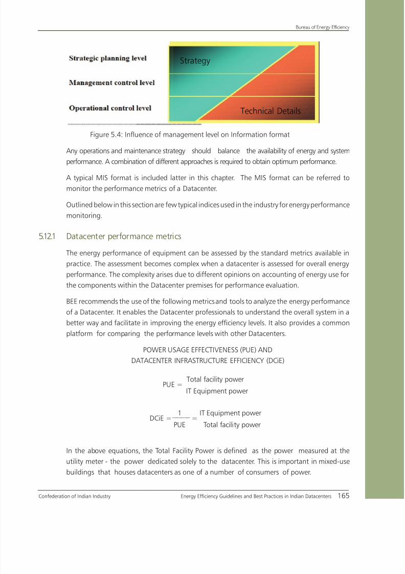
8/12/2019 CII & BEE Data Center Book
http://slidepdf.com/reader/full/cii-bee-data-center-book 185/250
Confederation of Indian Industry Energy Efficiency Guidelines and Best Practices in Indian Datacenters 165
Bureau of Energy Efficiency
Figure 5.4: Influence of management level on Information format
Any operations and maintenance strategy should balance the availability of energy and system
performance. A combination of different approaches is required to obtain optimum performance.
A typical MIS format is included latter in this chapter. The MIS format can be referred to
monitor the performance metrics of a Datacenter.
Outlined below in this section are few typical indices used in the industry for energy performance
monitoring.
5.12.1 Datacenter performance metrics
The energy performance of equipment can be assessed by the standard metrics available in
practice. The assessment becomes complex when a datacenter is assessed for overall energy
performance. The complexity arises due to different opinions on accounting of energy use for
the components within the Datacenter premises for performance evaluation.
BEE recommends the use of the following metrics and tools to analyze the energy performanceof a Datacenter. It enables the Datacenter professionals to understand the overall system in a
better way and facilitate in improving the energy efficiency levels. It also provides a common
platform for comparing the performance levels with other Datacenters.
POWER USAGE EFFECTIVENESS (PUE) AND
DATACENTER INFRASTRUCTURE EFFICIENCY (DCiE)
PUE =Total facility power
IT Equipment power
DCiE =1
=IT Equipment power
PUE Total facility power
In the above equations, the Total Facility Power is defined as the power measured at the
utility meter - the power dedicated solely to the datacenter. This is important in mixed-use
buildings that houses datacenters as one of a number of consumers of power.
Technical Details
Strategy

8/12/2019 CII & BEE Data Center Book
http://slidepdf.com/reader/full/cii-bee-data-center-book 186/250
Bureau of Energy Efficiency
166 Energy Efficiency Guidelines and Best Practices in Indian Datacenters Confederation of Indian Industry
The IT Equipment Power is defined as the equipment that is used to manage, process, store,
or route data within the data center. It is important to understand the components for the
loads in the metrics, which can be described as follows:
1. IT equipment power
This includes the load associated with all of the IT equipment, such as compute, storage,
and network equipment, along with supplemental equipment such as Keyboard, Video
or Visual display unit, Mouse (KVM) switches, monitors, and workstations/laptops used to
monitor or otherwise control the datacenter.
2. Total facility power
This includes everything that supports the IT equipment load such as:
Power delivery components such as UPS, switch gear, generators, PDUs, batteries,=
and distribution losses external to the IT equipmentCooling system components such as chillers, computer room air conditioning units=
(CRACs), direct expansion air handler (DX) units, pumps and cooling towers
Compute, network, and storage nodes=
Other miscellaneous component loads such as datacenter lighting=
As per the above explanations, both of these metrics imply the same; they can be used to
illustrate the energy allocation in the Datacenter in a different way, as shown in the subsequent
examples.
Example 1 - If a PUE is determined to be 2.0, this indicates that the datacenter demand
is two times greater than the energy necessary to power the IT equipment. In addition,the ratio can be used as a multiplier for calculating the real impact of the system power
demand.
Example 2 - If a server demands 400 watts and the PUE for the datacenter is 2.0, then the
power from the utility grid needed to operate 400 watts server is 800 watts.
The process of establishing the PUE or DCiE metric would be useful to determine:
Opportunities to improve a datacenter’s operational efficiency•
Comparisons with other datacenters•
Energy saving achieved through implemented measures, designs and processes•
Opportunities to re-route energy for additional IT equipment•

8/12/2019 CII & BEE Data Center Book
http://slidepdf.com/reader/full/cii-bee-data-center-book 187/250
Confederation of Indian Industry Energy Efficiency Guidelines and Best Practices in Indian Datacenters 167
Bureau of Energy Efficiency
DCiE is quite useful as well. A DCiE value of 50% (equivalent to a PUE of 2.0) indicates
that the IT equipment consumes 50% of the power in the datacenter.
Figure - 5.5: Power flow in a Datacenter
The utility metering in a multi-part building should have an exclusive meter for datacenter
operation, since power not intended to be consumed within the datacenter would result
in faulty PUE and DCiE metrics. For example, consider a datacenter located in an office
building. The total power drawn from the utility will be the sum of the Total Facility Power
for the datacenter, and the total power consumed by the non-datacenter offices. In this case
the datacenter administrator would have to measure or estimate the amount of power being
consumed by the non-datacenter offices (Estimation technique will introduce error in the
calculation).
IT Equipment Power is measured after all power conversions, switching, and conditioning is
completed and before the IT equipment itself is considered. The most likely measurement
point would be at the output of the computer room power distribution units (PDUs). The
measurement should represent the total power delivered to the compute equipment racks in
the datacenter.
Typically, the PUE range varies from 1.0 to 2.2. Ideally, a PUE value approaching 1.0 would
indicate 100% efficiency. (i.e. all power being used by IT equipment only)

8/12/2019 CII & BEE Data Center Book
http://slidepdf.com/reader/full/cii-bee-data-center-book 188/250
Bureau of Energy Efficiency
168 Energy Efficiency Guidelines and Best Practices in Indian Datacenters Confederation of Indian Industry
3. CUPS / WATT METRICS
Datacenter efficiency can also be estimated in CUPS/Datacenter Watts metrics. As discussed
earlier, using a low power processor can give cascading gains in energy savings. Based on this
premise, calculating Datacenter efficiency in terms of computing performance per watt usage
makes more sense. CUPS stands for Compute Usage Per Second. CUPS represents a proxy for
a universal measure of computing output.
5.12.2 Rack cooling performance index
Recommended Thermal Conditions:
The thermal conditions that may occur in a Datacenter are depicted in the figure 5.6. First,
facilities should be designed and operated to target the recommended range. Second, electronic
equipment should be designed to operate within the extremes of the allowable operating
environment. Prolonged exposure to temperatures outside the recommended range can result
in decreased equipment reliability and lowered longevity; exposure to temperatures outside the
allowable range may lead to catastrophic equipment failures. The recommended range and the
allowable range vary with the guidelines or standards used. For recommended temperatures,
the ASHRAE thermal guideline lists 68°- 77°f (20°-25°c) for a “class 1” environment.
Figure – 5.6: Rack Intake (vs) Rack Intake temperature

8/12/2019 CII & BEE Data Center Book
http://slidepdf.com/reader/full/cii-bee-data-center-book 189/250
Confederation of Indian Industry Energy Efficiency Guidelines and Best Practices in Indian Datacenters 169
Bureau of Energy Efficiency
Rack Cooling Indices (RCI):
The RCI is a metric used to measure the thermal condition of the electronic equipment.
Specifically, the RCIhi is a measure of the absence of over-temperatures (under-cooled
conditions); 100% means that no over-temperatures exist, and the lower the percentage, the
greater the probability that equipment experience excessive intake temperatures. RCI values
below 80% are generally considered “poor”.
Rack cooling indices are unit-independent indicators of cooling in a datacenter.
There are four types of temperatures defined for a rack or server, they are:
Maximum allowable temperature=
Maximum recommended temperature=
Minimum recommended temperature=
Minimum allowable temperature=
Based on these temperatures, unit-independent rack cooling indices RCIhi and RCI
lo are
formulated as below
RCIhi = {1 – [{Σ
(Tx − Tmax-rec)} / { (Tmax-all – Tmax-rec) n}] }100 %, for Tx>Tmax-recWhere Tx Mean temperature at intake x [°F or °C]
n Total number of intakes
Tmax-rec Max recommended temperature per some guideline or standard [°F or °C]
Tmax-all Max allowable temperature per some guideline or standard [°F or °C]
RCIlo = {1 – [{ Σ (Tmin-rec – Tx)} /{(Tmin-rec – Tmin-all) n }] }100 %, for Tx<Tmin-rec

8/12/2019 CII & BEE Data Center Book
http://slidepdf.com/reader/full/cii-bee-data-center-book 190/250
Bureau of Energy Efficiency
170 Energy Efficiency Guidelines and Best Practices in Indian Datacenters Confederation of Indian Industry
Where Tx Mean temperature at intake x [°F or °C]
n Total number of intakes [−]
Tmin-rec Min recommended temperature per some guideline or standard [°F or °C]
Tmin-all Min allowable temperature per some guideline or standard [°F or °C]
The interpretation of the indices is as follows:
RCIhi = 100% All intake temperatures ≤ max recommended temperature
RCIhi < 100% At least one intake temperature > max recommended temperature
RCIlo = 100% All intake temperatures ≥ min recommended temperature
RCIlo < 100% At least one intake temperature < min recommended temperature
The index is used to estimate the cooling level, which can be compared to the standard level
specified by the equipment manufacturer.
After calculating the index, based on the inference, the maintenance team can formulatespecific steps for performance improvement.
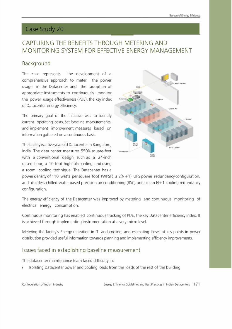
8/12/2019 CII & BEE Data Center Book
http://slidepdf.com/reader/full/cii-bee-data-center-book 191/250

8/12/2019 CII & BEE Data Center Book
http://slidepdf.com/reader/full/cii-bee-data-center-book 192/250
Bureau of Energy Efficiency
172 Energy Efficiency Guidelines and Best Practices in Indian Datacenters Confederation of Indian Industry
Metering the utilization of IT power, and cooling power at the right points in the power=
distribution cycle to facilitate collection of useful information for efficiency improvements
Identifying the optimum= levels of granularity for energy metering
Project details
The metering was done at three different levels to measure the total facility power, IT equipment power,
and cooling system power. Table 5.1 describes the location of meters in the system.
Table 5.1: Location of Datacenter power and cooling meters
Total facility power
Total facility power is the power measured at the utility meter that is dedicated solely to the Datacenter.
Datacenter total facility power includes everything that supports the IT equipment load, such as:
Power delivery com= ponents including UPS, switch gears, generators, power distribution units (PDUs),
batteries, and distribution losses external to the IT equipmentCooling system components such as chillers, computer room air conditioning (CRAC) units, direct=
expansion (DX) air handler units, pumps, cooling towers, and automation
Compute, network, and storage nodes=
Other miscellaneous component lo= ads, such as Datacenter lighting, the fire protection system, and so on
Figure 5.7 : Total facility power measurement

8/12/2019 CII & BEE Data Center Book
http://slidepdf.com/reader/full/cii-bee-data-center-book 193/250
Confederation of Indian Industry Energy Efficiency Guidelines and Best Practices in Indian Datacenters 173
Bureau of Energy Efficiency
IT equipment power
IT equipment power is defined as the effective power used by the equipment that manages, processes,
stores, or routes data within the raised floor space.
The IT equipment load includes:-
The load associated with all of the IT equipment such as compute, storage, and network=
equipment
Supplemental equipment such as keyboard, mouse, switches, monitors, workstations and= Laptops
used to monitor or otherwise control the Datacenter
Continuous monitoring of row-level energy consumption was found to be the more effective approach
to establish base line figures. Figure 5.8 shows the layout of Energy meters in the UPS system to
measure total IT power.
Figure 5.8: UPS metering layout to measure total IT power
To estimate the total IT power, energy meters were installed to measure the energy consumption at the
row level in the Datacenter. This enabled the metering and monitoring of the total power utilization
of the facility at a very granular level, providing differentiation between energy consumption for IT
equipment and for the facilities if the rest of the building.

8/12/2019 CII & BEE Data Center Book
http://slidepdf.com/reader/full/cii-bee-data-center-book 194/250
Bureau of Energy Efficiency
174 Energy Efficiency Guidelines and Best Practices in Indian Datacenters Confederation of Indian Industry
Cooling system power
The chilled water plant was common between the Datacenter, labs, and office space. Therefore flow
meters and temperature sensors were installed to measure the total cooling load of the building and
the Datacenter cooling load as well. All the meters were integrated with the building management
system (BMS) for continuous availability of measurements. Figure 5.9 shows the locations of energymeters for measuring cooling power.
Figure 5.9: Cooling power metering isolated datacenter
power from the facilities of the rest of the building
The continuous monitoring and analysis facilitated the implementation of the following energy saving
measures:
Paralleling the UPS to increase the utilization levels, thereby increasing efficiency and reducing=
distribution losses
Increasing the PAC temperature set point from 19 to 23 degrees Celsius=
Fine tuning the humidity level controls based on the requirement=
Managing airflow inside the data center=
Managing load across the data center floor=
Using LEDs for emergency lighting inside the Datacenter.=
Managing standard lighting to reduce energy consumption=
Results of the project
The initiatives demonstrated the method to continuously measure and manage the PUE in a
datacenter. It resulted in an annual operational power cost saving of Rs 3.85 million with more than
10 percent improvement in overall operational Datacenter efficiency in 2008. The PUE improved from
1.99 to 1.81. Despite an increase in the overall IT load, there has been a reduction in total facilities load.

8/12/2019 CII & BEE Data Center Book
http://slidepdf.com/reader/full/cii-bee-data-center-book 195/250
Confederation of Indian Industry Energy Efficiency Guidelines and Best Practices in Indian Datacenters 175
Bureau of Energy Efficiency
Table 5.2 and Figure 5.10 summarize the results achieved.
Table 5.2: Power Cost Savings Yielded by Improvements in Power Usage
Effectiveness (PUE) Efficiency and Projected Potential Savings
Figure 5.10: Total facilities load reduction
The project is essential and has to be customized based on the facility infrastructure•
The project involves minor modification/retrofit in the existing system.The project•
being capital intensive, has to be taken up as part of business decision

8/12/2019 CII & BEE Data Center Book
http://slidepdf.com/reader/full/cii-bee-data-center-book 196/250
Bureau of Energy Efficiency
176 Energy Efficiency Guidelines and Best Practices in Indian Datacenters Confederation of Indian Industry

8/12/2019 CII & BEE Data Center Book
http://slidepdf.com/reader/full/cii-bee-data-center-book 197/250
Chapter 6
Role of Management inDatacenter Energy Efficiency

8/12/2019 CII & BEE Data Center Book
http://slidepdf.com/reader/full/cii-bee-data-center-book 198/250

8/12/2019 CII & BEE Data Center Book
http://slidepdf.com/reader/full/cii-bee-data-center-book 199/250
Confederation of Indian Industry Energy Efficiency Guidelines and Best Practices in Indian Datacenters 179
Bureau of Energy Efficiency
6.0 Introduction
The Challenges in Datacenter Energy Management
The Datacenter in an organization is the locus of the storage and processing of vital
information in an electronic format; it is a critical area of operation.
Datacenters face two major challenges – maintaining hundred percent availability, and
achieving high energy efficiency. Resolving these two challenges requires astute management
as the provision of high availability negatively impacts energy efficiency and vice versa. This
happens because high availability is usually achieved through integrating multiple redundant
systems by design, and this automatically implies a lowering of the energy performance of
the overall system. This increases the operating costs of the Datacenter.
In order to maintain a balance between availability and energy efficiency, it is essential to
adopt energy-efficient equipment operating within in a highly efficient system. Organizing
such a system using the most suitable and energy-efficient equipment is the responsibility of
the Datacenter Management.
6.1 The role of management
The Management plays a crucial role not only in the creation of systems and the sourcing of
equipment, but also in its operation and maintenance.
The energy management of Datacenters is governed, ultimately, by the operating condition
of the system and equipment.The operating conditions in turn, are directly related to the
knowledge levels and involvement of the maintenance personnel. Therefore the success ofachieving and sustaining energy savings depends on the knowledge level of the technical
personnel (maintenance) and their involvement in the goal of achieving maximum energy
efficiency.
It is the Management that has to create a platform for technical personnel to continuously
improve their knowledge levels by creating opportunities for them to participate in a
variety of awareness programs. It is also the Management that has to take the initiative
to create and sustain a dedicated energy efficiency Cell, whose members would primarily
be concerned with the energy management strategies of the Datacenter. This special cell
should be entrusted with conceiving and implementing an energy management plan thatsubsumes the whole spectrum of energy conservation activities such as measurement,
sub-measurement and logging of energy-related parameters, calibration programs, energy
audits, energy performance assessments, and budget allocations for introducing and
sustaining productive energy-efficiency measures. In order to conceive of and carry through
such an energy management plan, the energy efficiency Cell requires the full support of the
Datacenter Management.

8/12/2019 CII & BEE Data Center Book
http://slidepdf.com/reader/full/cii-bee-data-center-book 200/250
Bureau of Energy Efficiency
180 Energy Efficiency Guidelines and Best Practices in Indian Datacenters Confederation of Indian Industry
The following pages elaborate on various energy management strategies that the Management
can implement in order to achieve maximum energy efficiency in the Datacenter.
6.2 Energy management strategies
creation of an Energy Management CellSuccessful energy management requires a dedicated Cell – whether it consists of a single
energy manager / coordinator or a number of middle managers - working towards planning
and implementing it. Only then does the responsibility for energy efficiency and conservation
devolve onto a single entity.Such a Cell would occupy a position in the hierarchy somewhere
between senior management and the end-users of energy. Leading, coordinating, overseeing
and championing energy conservation activities in the Datacenter would be its sole concerns.
Organizing awareness programs
In general, Datacenter maintenance personnel are primarily concerned only with maintaining
uptime, and strategizing capacity addition for future growth. Energy efficiency generally finds
a place only towards the end in their list of priorities. To change this focus, and reinvent
energy conservation and efficiency hiking activities as high-priority activities, the Management
has to organize awareness programs to involve and motivate the personnel responsible for
the operation of Datacenters. The Management should carry out the following employee
motivational activities to generate and sustain interest in energy conservation activities:
Send operating/ maintenance personnel for training programs on specific areas such as=
Server management , storage issues, air management, power distribution management,
chiller design and operation, etc
Organize regular meeting between executives and technology suppliers to enable=
personnel to keep abreast of the latest developments in Datacenter infrastructure
management technologies
Encourage the conduct of seminars and other knowledge-sharing activities in which=
papers on energy conservation activities can be presented and the latest information in
this area can be evaluated
Implementing an Energy Management Plan
Energy management planning involves a cycle of activities: evaluating the energy conservation
schemes in an organization, identifying strengths, short-falls, and areas offering scope for
positive change, implementing improved systems, procedures and techniques. It acts as a
recursive plan for energy efficiency improvement.
The energy management plan should address:
The process of identification, implementation and evaluation of energy saving schemes=

8/12/2019 CII & BEE Data Center Book
http://slidepdf.com/reader/full/cii-bee-data-center-book 201/250
Confederation of Indian Industry Energy Efficiency Guidelines and Best Practices in Indian Datacenters 181
Bureau of Energy Efficiency
Training of personnel=
The formulation of strategies to improve efficiency levels, by setting specific time-bound=
targets, among other measures
The involvement of management, middle level managers, operation and maintenance=
personnel in making energy conservation a sustained activity
6.3 Some components of an energy management plan
Measurement
Measuring energy consumption by logging the energy usage of all the key components in a
Datacenter influence decisions involving any modification for performance improvement. The
availability of such data eases the process of maintenance by indicating any abnormalities in
operation, and thus helps improve the reliability and energy-efficiency of the system.
In order to collect such data, Sub-meters should be installed at key locations to measureenergy distribution between IT equipment and support systems. An analysis of the readings of
these sub-meters is a powerful tool that accurately measures energy usage and helps in the
preparation of an energy balance for the entire system. It enables the monitoring of system
performance over the time and provides evidence of positive and negative changes in energy
consumption patterns. degradation and improvements.
Instrument calibration program
Since measurement plays a vital role in monitoring energy efficiency in a system, it is
necessary to ensure the accuracy of the measurements. Running regular programs to verify
and calibrate the accuracy of sensors helps to ensure their accuracy, and therefore validates
comparisons made over time. Such programs would involve verifying the accuracy of the
measuring instrument and re-calibrating it to the measurement standard if required.
Particular attention must be paid to the regular maintenance, verification and calibration of
instruments measuring key input parameters. It is also important to maintain a log that
records the calibration information of all the pieces of equipment.
Energy audit
An energy audit is a systematic check-up that offers a real-time profile and model of the
Datacenter’s energy use conditions, making it possible to identify areas of high energy use and
establish a baseline for further improvement activities.
What is being measured, can be managed
What is being measured well, can be managed well

8/12/2019 CII & BEE Data Center Book
http://slidepdf.com/reader/full/cii-bee-data-center-book 202/250
Bureau of Energy Efficiency
182 Energy Efficiency Guidelines and Best Practices in Indian Datacenters Confederation of Indian Industry
An energy audit involving experts from an external agency would fine-tune the internal
process or approach and would help the internal team to identify areas where there is scope
for efficiency improvement. Based on the audit, several energy saving activities, like capacity
utilization, fine tuning of processes and adopting the latest energy-saving technologies, can
be initiated.
Performance assessment
The energy consumed in a Datacenter is utilized for both IT equipment and its support systems.
In general, the efficient operation of each of these is assessed and maintained. However, the
energy performance of a Datacenter on the whole, is reflected in the effective ratio of the
energy utilization for IT equipment, to that for the support systems. The overall performance
can be estimated by adopting metrics such as :
PUE (Power Utilization Effectiveness)=
DCIE (Datacenter Infrastructure Efficiency).=
Both these measurements indicate how much energy the support systems use in comparison
to the IT equipment itself.
The energy utilized for support systems has direct no business-value but has an impact on
the cost of operation. The lesser energy the support systems use for a given IT load, the more
efficiently the facility operates. Hence, it is necessary to reduce the energy use for support
systems to improve the overall performance of a Datacenter. Continuously monitoring this
ratio is a good way to keep track of the performance of the whole Datacenter.
Budget allocationRational budgeting is a must for implementing energy saving measures in the plant. Budgets
for such measures should be made available under the guiding policies of the company. Each
investment should be evaluated thoroughly on its technical feasibility and economic viability
through ROI calculations like simple pay back period, IRR etc. Budget allocation should be
done on an yearly basis and intimated to the Energy Management Cell at the beginning of
the year, for the smooth execution of activities. Top management can retain the power for
sanctioning larger investments, but decisions on marginal investments should be left to lower
or middle management.
Management may choose not to fund a project based on the capital expenditure. The Energy
Management team has to clearly present the analysis of the return on investment (ROI) of the
proposed action, which will help the Management to compare it to alternative investment
options .

8/12/2019 CII & BEE Data Center Book
http://slidepdf.com/reader/full/cii-bee-data-center-book 203/250
Confederation of Indian Industry Energy Efficiency Guidelines and Best Practices in Indian Datacenters 183
Bureau of Energy Efficiency
6.4 Conclusion
Demonstrating the Management’s participation in and commitment to energy management
goals, in various ways, is very important. Some of these ways could be framing an energy
management plan in accordance with the organization’s energy management policy, regular
review of energy management projects, the organizing of informational and motivational
programs for personnel, and conceptualizing incentive programs that encourage employees
to undertake sustained energy conservation activities.
The Management’s attitude towards energy efficiency and conservation, as demonstrated by
its actions, sets the tone for the whole organization’s perception of these issues. Therefore, the
onus of initializing and sustaining energy conservation activities in the organization rests with
the Management. Positive and proactive energy conservation and energy efficiency increasing
measures, undertaken at the Management level, would go a long way in seeing the Indian
Datacenter industry emerge as a world leader in energy management.

8/12/2019 CII & BEE Data Center Book
http://slidepdf.com/reader/full/cii-bee-data-center-book 204/250

8/12/2019 CII & BEE Data Center Book
http://slidepdf.com/reader/full/cii-bee-data-center-book 205/250

8/12/2019 CII & BEE Data Center Book
http://slidepdf.com/reader/full/cii-bee-data-center-book 206/250
Bureau of Energy Efficiency
186 Energy Efficiency Guidelines and Best Practices in Indian Datacenters Confederation of Indian Industry
Annexure-2
Air Management and Air Distribution Metrics(Source: Texas Instruments)
Rack Cooling Index (RCI):
RCI is a dimensionless measure of how effectively the equipment is cooled within a given intake
temperature specification. It provides a measure of the conditions at the high (HI) end and at the
low (LO) end of the specified temperature range. RCIHI=100% means that no intake temperature is
above the maximum recommended, and RCILO=100% means that no intake temperature is below
the minimum recommended. Using ASHRAE Class 1 temperature specification, “poor” conditions are
≤90% whereas “good” conditions are ≥96%. The RCI is assuming the ASHRAE Class 1 recommended
intake temperature.
Return Temperature Index (RTI):
The Return Temperature Index (RTI) is a dimensionless measure of the actual utilization of the available
temperature differential in the equipment room as well as a measure of the level of by-pass air or
recirculation air in the Datacenter. 100% is generally the target; >100% ® recirculation air; <100% ®
by-pass air.
Supply Heat Index (SHI):
The Supply Heat Index (SHI) is a dimensionless measure of recirculation of hot air into the cold aisles.
SHI is a number between 0 and 1 and the lower the better. SHI is typically < 0.40. An SHI = 0 means
that all inlet temperatures are equal to the supply temperature.

8/12/2019 CII & BEE Data Center Book
http://slidepdf.com/reader/full/cii-bee-data-center-book 207/250
Confederation of Indian Industry Energy Efficiency Guidelines and Best Practices in Indian Datacenters 187
Bureau of Energy Efficiency
Annexure-3
Twenty-Seven Things Can be done to Meet
“24 by Forever” Expectations
(Source: Uptime Institute)
1. Create a Raised-Floor Master Plan
2. Install computer and infrastructure equipment cabinets in the Cold Aisle/Hot Aisle arrangement
a. 14’ cold aisle to cold aisle separation with cabinets ≤ 42” deep
b. 16’ cold aisle to cold aisle separation with cabinets > 42” to 48” deep
3. Utilize proper spacing of the cold aisles
a. 48” wide with two full rows of tiles which can be removed b. All perforated tiles are only located in the cold aisle
4. Utilize proper spacing of the hot aisles
a. Minimum 36” with at least one row of tiles able to be removed
b. Do not place perforated tiles in the hot aisle
5. Place cooling units at the end of the equipment rows
a. Aligned with hot aisles where possible
6. Face cooling units the same direction
a. No “circle the wagons,” a.k.a., uniformly distributed cooling
7. Limit maximum cooling unit throw distance to 50’
8. Create appropriate cooling capacity, with redundancy, in each zone of the room (zone maximum is
one to two building bays)
a. Install minimum of two cooling units even if only one needed.
b. Install one-in-six to one-in-eight redundant cooling units in larger areas
9. Use only sensible cooling at 72°F/45% RH when calculating the capacity of cooling units
10. Establish minimum raised- floor height
a. 24” if the cabling is overhead, with no chilled water or condenser water pipes under the floor
blocking the air flow.
b. Recommend 30” to 36” if there are air flow blockages.
8/12/2019 CII & BEE Data Center Book
http://slidepdf.com/reader/full/cii-bee-data-center-book 208/250
Bureau of Energy Efficiency
188 Energy Efficiency Guidelines and Best Practices in Indian Datacenters Confederation of Indian Industry
11. Place chilled or condenser water pipes in suppressed utility trenches if the computer room is built
on grade
12. Establish a minimum clearance of 3’ from the top of the cabinets to a ceiling
13. Put Power Distribution Units and Remote Power Panels in line with computer equipment cabinet
rows occupying cabinet positions
14. The maximum number of perforated tiles is the total cooling unit air flow divided by 750 cfm =
maximum number of perforated tiles to be installed.
a. Install only the number of perforated tiles necessary to cool the load being dissipated in the
cabinet/rack in the area immediately adjacent to the perforated tile.
b. Turn off cooling units that are not required by the heat load (except for redundant units)
15. Do not use perforated tile air flow dampers and remove all existing dampers from the bottoms of
perforated tiles (reduces maximum air flow by 1/3, they often close unexplainably and they
potentially can produce zinc whiskers).
16. Ensure cabinets are installed with the front face of the frame set on a tile seam in the cold aisle
17. Require cabinet door faces to have a minimum of 50 percent open perforation, 65 percent is
better
18. Seal all cable cutouts and other openings in the raised floor with closures. Triton KoldLok®grommets
are one solution.
19. Seal all penetrations in the sub floor and perimeter walls under the raised oor and above thedropped ceiling
20. Spread power cables out on the sub oor, preferably under the cold aisle to minimize airflow
restrictions
21. Place data cables in trays at the stringer level in the hot aisle
22. If overhead cable racks are used, the racks should run parallel to the rows of racks. Crossover
points between rows of racks should be located as far from the cooling units serving the area as
practical
23. Prevent internal hot air recirculation by sealing the front of cabinets with blanking plates, including
empty areas in the equipment-mounting surface, between the mounting rails, and the edges of
the cabinets (if necessary)
24. Ensure all cooling units are functioning properly:
a. Set points and sensitivities are consistent

8/12/2019 CII & BEE Data Center Book
http://slidepdf.com/reader/full/cii-bee-data-center-book 209/250
Confederation of Indian Industry Energy Efficiency Guidelines and Best Practices in Indian Datacenters 189
Bureau of Energy Efficiency
b. Return air sensors are in calibration—calibrate the calibrator
c. Air flow volume is at specified level
d. Unit is functioning properly at return air conditions
e. Unit produces ≥ 15 F delta T at 100 percent capacity.
25. Be sure the cooling unit’s blower motor is turned off if the throttling valve sticks (chilled water type
units) or if a compressor fails (air conditioning type unit)
26. Adjust chilled water temperature to eliminate latent cooling
27. Monitor and manage the critical parameters associated with equipment installation, by area of
the computer room (no more than two building bays)
a. Space: Number of cabinets and rack unit space available versus utilized
b. Power: PDU output available versus utilized
c. Breaker positions: available versus utilized
d. Sensible/Redundant cooling capacity available versus utilized
e. Floor loading: acceptable weight versus installed cabinet and equipment weight plus dead
load of floor and cables, plus live load of people working in area. Compare the actual load
with the sub floor structural strength
8/12/2019 CII & BEE Data Center Book
http://slidepdf.com/reader/full/cii-bee-data-center-book 210/250
Bureau of Energy Efficiency
190 Energy Efficiency Guidelines and Best Practices in Indian Datacenters Confederation of Indian Industry
Annexure-4
Datacenter Benchmarking Guide(Source : Lawrence Berkeley National Laboratory, US)
I. Overall Data Center Performance Metrics
Overall Data Center PerformanceMetrics
B1: Data Center Infrastructure Efficiency (DCiE)
Description:
This metric is the ratio of the IT equipment energy to the total data center energy use. The totaldata center energy use is the sum of the electrical energy for IT, HVAC system, power
distribution, lighting, and any other form of energy use, like steam or chilled water. All the
energy data values in the ratio are converted to common units.
Units: Dimensionless
B1 = dE2 ÷ (dE1 + (dE4 + dE5 + dE6)
where:
dE1: Total Electrical Energy Use (kWh)
dE2: IT Electrical Energy Use (kWh)
dE4: Total Fuel Energy Use (kWh)
dE5: Total District Steam Energy Use (kWh)
dE6: Total District Chilled Water Energy Use (kWh)
B2: Power Usage Effectiveness (PUE)
Description:
PUE is the inverse of the DCiE metric. This metric is the ratio of the total data center energy use
to total IT energy use. The total data center energy use is the sum of the electrical energy for the
servers, HVAC system, power distribution, lighting, and any other form of energy use, like
steam or chilled water. All the energy data values in the ratio are converted to common units.
Units: Dimensionless
B2 = (dE1 + (dE4 + dE5 + dE6) ÷ dE2
where:
dE1: Total Electrical Energy Use (kWh)
dE2: IT Electrical Energy Use (kWh)
dE4: Total Fuel Energy Use (kWh)
dE5: Total District Steam Energy Use (kWh)
dE6: Total District Chilled Water Energy Use (kWh)
ID Name Priority
B1 Data Center Infrastructure Efficiency 1
B2 Power Usage Effectiveness 1
B3 HVAC System Effectiveness 1

8/12/2019 CII & BEE Data Center Book
http://slidepdf.com/reader/full/cii-bee-data-center-book 211/250
Confederation of Indian Industry Energy Efficiency Guidelines and Best Practices in Indian Datacenters 191
Bureau of Energy Efficiency
B3: HVAC System Effectiveness
Description:
This metric is the ratio of the IT equipment energy to the HVAC system energy. The HVAC
system energy is the sum of the electrical energy for cooling, fan movement, and any other
HVAC energy use like steam or chilled water.
Units: Dimensionless
B3 = dE2 ÷ (dE3 + (dE4 + dE5 + dE6)
where:
dE2: IT Electrical Energy Use (kWh)
dE3: HVAC Electrical Energy Use (kWh)
dE4: Total Fuel Energy Use (kWh)
dE5: Total District Steam Energy Use (kWh)
dE6: Total District Chilled Water Energy Use (kWh)
II. Air Management Metrics
ID Name Priority
A1 Temperature Range1
A2 Humidity Range1
A3 Return Temperature Index1
A4 Airflow Efficiency1
A1: Temperature: Supply and Return
Description:
This metric is the difference between the supply and return air temperature from the IT
equipment in the data center.
Units:oC
A1 = dA2 – dA1
where:
dA1: Supply air temperature
dA2: Return air temperature
A2: Relative Humidity: Supply and Return
Description:
This metric is the difference of the return and supply air relative humidity from the IT equipment
in the data center.
Units: % RH
A2 = dA4 – dA3

8/12/2019 CII & BEE Data Center Book
http://slidepdf.com/reader/full/cii-bee-data-center-book 212/250
8/12/2019 CII & BEE Data Center Book
http://slidepdf.com/reader/full/cii-bee-data-center-book 213/250
Confederation of Indian Industry Energy Efficiency Guidelines and Best Practices in Indian Datacenters 193
Bureau of Energy Efficiency
C1: Data Center Cooling System Efficiency
Description:
This metric characterizes the overall efficiency of the cooling system (including chillers, pumps,
and cooling towers) in terms of energy input per unit of cooling output. It is an average value
depicting average power of the cooling system with respect to the cooling load in the data center.
Units: kW/ton
C1: (dC1) ÷ (dC2)
where:
dC1: Average cooling system power usage (kW)
dC2: Average cooling load in the data center (tons)
C2: Cooling System Sizing Factor
Description:
This metric is the ratio of the installed cooling capacity to the peak cooling load.Units: -
C2 = dT8 ÷ dT9
where:
dT8: Installed Chiller Capacity (w/o backup) (tons)
dT9: Peak Chiller Load (tons)
C3: Air Economizer Utilization Factor
Description:
This metric characterizes the extent to which air-side economizer system is being used to provide
“free” cooling. It is defined as the percentage of hours in a year that the economizer system can be in full or complete operation (i.e. without any cooling being provided by the chiller plant).
Units: %
C3 = (dC5 ÷ 8760) × 100
where:
dC5: Air economizer hours (full cooling)

8/12/2019 CII & BEE Data Center Book
http://slidepdf.com/reader/full/cii-bee-data-center-book 214/250
Bureau of Energy Efficiency
194 Energy Efficiency Guidelines and Best Practices in Indian Datacenters Confederation of Indian Industry
C4: Water Economizer Utilization Factor
Description:
This metric is the percentage hours in a year that the water side economizer system meets the
entire cooling load of the data center.
Units: %
C4 = (dC6 ÷ 8760) × 100
where:
dC6: Water economizer hours (full cooling)
IV. Electrical Power Chain Metrics
P1: UPS Load Factor
Description:
This metric is the ratio of the load of the uninterruptible power supply (UPS) to the design value
of its capacity. This provides a measure of the UPS system over-sizing and redundancy.Units: Dimensionless
P1 = dP1 ÷ dP2
where:
dP1: UPS peak load (kW)
dP2: UPS load capacity (kW)
P2: Data Center UPS System Efficiency
Description:
This metric is the ratio of the UPS input power to the UPS output power. The UPS efficiency
varies depending on its load factor.
Units: %
P2 = dP3 ÷ dP4
where:
dP3: UPS input power (kW)
ID Name Priority
P1 UPS Load Factor 1
P2 UPS System Efficiency 1
P3 IT or Server Equipment Load Density 1
P4 Lighting Density 3
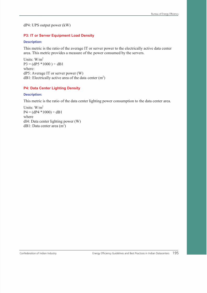
8/12/2019 CII & BEE Data Center Book
http://slidepdf.com/reader/full/cii-bee-data-center-book 215/250
Confederation of Indian Industry Energy Efficiency Guidelines and Best Practices in Indian Datacenters 195
Bureau of Energy Efficiency
dP4: UPS output power (kW)
P3: IT or Server Equipment Load Density
Description:
This metric is the ratio of the average IT or server power to the electrically active data center
area. This metric provides a measure of the power consumed by the servers.
Units: W/m2
P3 = (dP5 *1000 ) ÷ dB1
where:
dP5: Average IT or server power (W)
dB1: Electrically active area of the data center (m2)
P4: Data Center Lighting Density
Description:
This metric is the ratio of the data center lighting power consumption to the data center area.Units: W/m2
P4 = (dP4 *1000) ÷ dB1
where
dI4: Data center lighting power (W)
dB1: Data center area (m2)

8/12/2019 CII & BEE Data Center Book
http://slidepdf.com/reader/full/cii-bee-data-center-book 216/250
Bureau of Energy Efficiency
196 Energy Efficiency Guidelines and Best Practices in Indian Datacenters Confederation of Indian Industry
Data Required for Performance Metrics
ID Data Item Measurement/Calculation Guidance
General Data Center Data
dB1 Data Center Area (electrically active)dB2 Data Center Location
dB3 Data Center Type
dB4 Year of Construction (or major renovation)
Data Center Energy Data
dE1 Total Electrical Energy Use
dE2 IT Electrical Energy Use
dE3 HVAC Electrical Energy Use
dE4 Total Fuel Energy Use
dE5 Total District Steam Energy Use
dE6 Total District Chilled Water Energy Use
Air ManagementdA1 Supply Air Temperature
dA2 Return Air Temperature
dA3 Supply Air Relative Humidity
dA4 Return Air Relative Humidity
dA5 Rack Inlet Mean Temperature
dA6 Rack Outlet Mean Temperature
dA7 Total Fan Power (Supply and Return)
dA8 Total Fan Airflow rate (Supply and Return)
Cooling
dC1 Average Cooling System Power Consumption
dC2 Average Cooling Load
dC3 Installed Chiller Capacity (w/o backup)
dC4 Peak Chiller Load
dC5 Air Economizer Hours (full cooling)
dC6 Water Economizer Hours (full cooling)
Electrical Power Chain
dP1 UPS Peak Load
dP2 UPS Load Capacity
dP3 UPS Input Power
dP4 UPS Output Power
dP5 Average IT or Server Power
dP6 Average Lighting Power

8/12/2019 CII & BEE Data Center Book
http://slidepdf.com/reader/full/cii-bee-data-center-book 217/250
Confederation of Indian Industry Energy Efficiency Guidelines and Best Practices in Indian Datacenters 197
Bureau of Energy Efficiency
Annexure-5
List of Energy saving opportunities in Datacenter
Title Page No.
Case Study 1 - Power Quality Improvement In A Datacenter By InstallingHarmonic Filters
43
Case Study 2 - Energy Efficiency Improvement In UPS Systems By LoadingOptimization
46
Case Study 3 - Energy Efficiency Improvement in Lighting System ByReplacing Fluorescent Lamps With Light Emitting Diode(Lted) Lamps
50
Case Study 4 - Potential benefits of economizer in cooling system 81
Case Study 5 - Introduction of Intelligent Controller for multiple Crac unitsystem
85
Case Study 6 - Benefits of Electronically Commutted (Ec) Fans ForVarying Air Requirement
88
Case Study 7 - Potential benefits of hot Aisle/Cold Aisle Containment 91
Case Study 8 - Introduction of systematic cable Management ForBetter Air Distribution in Raised Floor System
95
Case Study 9 - Benefits of humidity Control for Energy Efficiency in Datacenter
97
Case Study 10 - Benefits of redefining Inlet Conditions For Energy Efficiencyin Datacenter
100
Case Study 11 - Benefits of water cooled cabinets in cooling system105
Case Study 12 - Operate IT Equipment Cooling System at a HigherTemperature Difference
107
Case Study 13 - CFD Simulation For Enhanced Datacenter Productivity 109
Case Study 14 - Thermal Storage System For Emergency Cooling Requirements
111
Case study 15 - Benefits of a ccelerated server refresh strategy 134
Case study 16 - Enterprise computing performance improvement through consolidation of datacenters
137
Case study 17 - Network virtualization for performance Improvement 139
Case study 18 - Effective storage utilization optimizes datacenteroperational cost
141
Case study 19 - Infrastructure efficiency improvement in avirtualized environment
144
Case study 20 - Capturing the benefits through metering andmonitoring system for effective energy management
170

8/12/2019 CII & BEE Data Center Book
http://slidepdf.com/reader/full/cii-bee-data-center-book 218/250

8/12/2019 CII & BEE Data Center Book
http://slidepdf.com/reader/full/cii-bee-data-center-book 219/250
Confederation of Indian Industry Energy Efficiency Guidelines and Best Practices in Indian Datacenters 199
Bureau of Energy Efficiency
References
Sun Microsystems white paper on “Energy efficient datacenters - The role of modularity in datacenter=
design”Pacific Gas & Electric company’s design guidelines source book on “High performance=
Datacenters”
Sun Microsystems white paper on “Energy efficient datacenters - Electrical design”=
Lawrence Berkeley National Laboratory’s report on “DC Power for Improved Datacenter Efficiency”=
Schneider electric’s white paper on “DC Power for Improved Datacenter Efficiency”=
University of Southern California white paper on “Minimizing Datacenter Cooling and Server Power=
Costs” by Ehsan Pakbaznia and Massoud Pedram
Green Grid white paper by “Green grid Datacenter power efficiency metrics: PUE and DCiE”=
Green Grid white paper on “Seven strategies to improve Datacenter cooling efficiency”=
Green Grid white paper on “The Green Grid metrics: Datacenter infrastructure efficiency (DCiE)=
detailed analysis”
Green Grid white paper on “Guide lines for Energy-Efficient Datacenters”=
Intel’s white paper on “Air-Cooled High-Performance Datacenters: Case Studies and Best Methods”=
http://www.searchdatacenter.com – white paper on “Green Datacenter Efficiency Developments”=
by Brocade
IBM’s white paper on “Championing Energy Efficiency in the Datacenter: An IBM Server Consolidation=
Analysis” April 20, 2007
Intel’s white paper on “Intel Eco-Rack Version 1.5”=
Intel’s white paper on “Turning Challenges into Opportunities in the Datacenter”=
Sun Microsystems white paper on “Sun Professional Services Sample Case Studies”=
APC white paper on “Datacenter Projects: Establishing a Floor Plan” By Neil Rasmussen & Wendy=
Torell
CARYAIRE bulletin on “Air distribution products”=
APC white paper on “ Rack Powering Options for High Density in 230VAC Countries”=
Intel white paper on “Reducing Datacenter Energy Consumption with Wet Side Economizers” May=
2007
Intel white paper on “Reducing Datacenter Cost with an Air Economizer” August 2008=
APC white paper on “A scalable, reconfigurable, and efficient Datacenter power distribution=
architecture”

8/12/2019 CII & BEE Data Center Book
http://slidepdf.com/reader/full/cii-bee-data-center-book 220/250
Bureau of Energy Efficiency
200 Energy Efficiency Guidelines and Best Practices in Indian Datacenters Confederation of Indian Industry
APC white paper on “Reliability Models for Electric Power Systems”=
APC white paper on “Comparing UPS System Design Configurations”=
ACEEE report on “Best Practices for Datacenters: Lessons Learned from Benchmarking 22=
Datacenters”
Cisco white paper on “Datacenters: Best practices for security and performance”=
Green Grid white paper on “Fundamentals of Datacenter power and cooling efficiency zones”=
NetApp white paper on “Case Study: NetApp Air Side Economizer”=
US Environmental Protection Agency report to Congress on Server and Datacenter Energy Efficiency,=
August 2007
Colorado Springs Utilities white paper on “Energy Efficiency in Computer Datacenters”=
PTS Datacenter solutions white paper on “Datacenter Cooling Best Practices”=
Cadence project report on “PC Quest best implementations of the year 2009”=
Cisco systems white paper on “Airport Uses Network Virtualization to Consolidate and Scale=
Operations”
Cisco systems white paper on “Cisco slashes storage costs with storage recovery program”=
Cisco best practices manual on “Storage Utilization management”=
Cisco systems white paper on “Network Virtualization for the campus”=
CtrlS manual on “Datacenter design philosophy”=
Emerson Network power write-up on “Best Datacenter design practices”=
Hewlett Packard white paper on “Storage works virtualization”=
Hewlett Packard white paper on “Virtualization in business terms”=
Intel white paper on “Accelerated server refresh reduces datacenter cost”=
Intel white paper on “Building an enterprise data warehouse and business intelligence solution”=
Intel white paper on “Expanding Datacenter capacity using water cooled cabinets”=
Intel white paper on “Implementing Virtualization in global business-computing environment”=
Intel white paper on “Increasing datacenter efficiency through metering and monitoring power=
usage”
Intel white paper on “Reducing datacenter cost with an air economizer”=
Intel white paper on “Energy efficient performance for the datacenter”=
Intel white paper on “Reducing storage growth and cost – A comprehensive approach to storage=
optimization”
Intel white paper on “Thermal storage system provides emergency datacenter cooling”=
International Resources Group ECO-III Project report on “ Datacenter Benchmarking guide”=
BMC software education services solution guide on “Managing Datacenter Virtualization”=

8/12/2019 CII & BEE Data Center Book
http://slidepdf.com/reader/full/cii-bee-data-center-book 221/250
Confederation of Indian Industry Energy Efficiency Guidelines and Best Practices in Indian Datacenters 201
Bureau of Energy Efficiency
Cisco design guide on “Datacenter infrastructure”=
DELL & Intel white paper on “Datacenter Operation and Maintenance best practices for critical=
facilities”
Texas Instrument presentation on “Technical audit report”=
Emerson Network power white paper on “Five Strategies for Cutting Datacenter Energy Costs=
Through Enhanced Cooling Efficiency”
Eaton white paper on “Economic and electrical benefits of harmonic reduction methods in=
commercial facilities”
Emerson Network power report on “Technical Note: Using EC Plug Fans to Improve Energy Efficiency=
of Chilled Water Cooling Systems in Large Datacenters”
APC white paper on “Virtualization: Optimized Power and Cooling to Maximize Benefits”=
8/12/2019 CII & BEE Data Center Book
http://slidepdf.com/reader/full/cii-bee-data-center-book 222/250
Bureau of Energy Efficiency
202 Energy Efficiency Guidelines and Best Practices in Indian Datacenters Confederation of Indian Industry
TERMS AND DEFINITIONS
Source : Green Grid
Blanking panels - Panels typically placed in unallocated portions of enclosed IT equipment racks to
prevent internal recirculation of air from the rear to the front of the rack.
Bus, power (or electrical bus) - A physical electrical interface where many devices share the same electric
connection, which allows signals to be transferred between devices, allowing information or power to
be shared
Chiller - A heat exchanger using air, refrigerant, water and evaporation to transfer heat to produce air
conditioning. A chiller is comprised of an evaporator, condenser and compressor system.
Cooling tower - Heat-transfer device, often tower-like, in which atmospheric air cools warm water,
generally by direct contact (heat transfer and evaporation).
CRAC (Computer Room Air Conditioner) - A modular packaged environmental control unit designed
specifically to maintain the ambient air temperature and/or humidity of spaces that typically contain
Datacenter equipment. These products can typically perform all (or a subset) of the following functions:
cool, reheat, humidify, dehumidify.
Dehumidifier - A device that removes moisture from air.
Economizer, air – A ducting arrangement and automatic control system that allow a cooling supply
fan system to supply outdoor (outside) air to reduce or eliminate the need for mechanical refrigeration
during mild or cold weather
Economizer, water - A system by which the supply air of a cooling system is cooled directly or indirectly
or both by evaporation of water or by other appropriate fluid (in order to reduce or eliminate the need
for mechanical refrigeration)
Efficiency - The ratio of the output to the input of any system. Typically used in relation to energy;
smaller amounts of wasted energy denote high efficiencies.
Free standing equipment - Equipment that resides outside of Datacenter racks.
Generator - A machine, often powered by natural gas or diesel fuel, in which mechanical energy is
converted to electrical energy
Hot aisle/cold aisle - A common means to optimize cooling in IT equipment rooms by arranging IT
equipment in back-to-back rows. Cold supply air from the cold aisle is pulled through the inlets of the
IT equipment, and exhausted to a hot aisle to minimize recirculation

8/12/2019 CII & BEE Data Center Book
http://slidepdf.com/reader/full/cii-bee-data-center-book 223/250
Confederation of Indian Industry Energy Efficiency Guidelines and Best Practices in Indian Datacenters 203
Bureau of Energy Efficiency
Humidifier - A device which adds moisture to the air.
Load - In Datacenters, load represents the total power requirement of all Datacenter equipment (typically
servers and storage devices, and physical infrastructure).
PDU (Power Distribution Unit) – A floor or rack mounted enclosure for distributing branch circuit
electrical power via cables, either overhead or under a raised floor, to multiple racks or enclosures of
IT equipment. The main function of a PDU is to house circuit breakers that are used to create multiple
branch circuits from a single feeder circuit. A secondary function of some PDUs is to convert voltage. A
Datacenter typically has multiple PDUs.
Pump - Machine for imparting energy to a fluid, causing it to do work.
Rack - Structure for housing electronic equipment.
Raised floor - Raised floors are a building system that utilizes pedestals and floor panels to create a
cavity between the building floor slab and the finished floor where equipment and furnishings arelocated. The cavity can be used as an air distribution plenum to provide conditioned air throughout the
raised floor area. When used as an access floor, the cavity can also be used to rout power/data cabling
infrastructure and/or water or coolant piping.
rPDU – (Rack-mount Power Distribution Unit) – A device designed to mount in IT equipment racks or
cabinets, into which units in the rack are plugged to receive electrical power
Transformer - A device used to transfer an alternating current or voltage from one circuit to another by
means of electromagnetic induction.
UPS (Uninterruptible Power Supply) fixed - Typically uses batteries as an emergency power source
to provide power to Datacenter facilities until emergency generators come on line. Fixed implies a
standalone unit hard wired to the building.
UPS (Uninterruptible Power Supply) modular/scalable - Typically uses batteries as an emergency power
source to provide power to Datacenter facilities until emergency generators come on line. Modular/
scalable implies units installed in racks with factory-installed whips allowing for physical mobility and
flexibility.
Air intake - Device that allows fresh air to enter into the building.

8/12/2019 CII & BEE Data Center Book
http://slidepdf.com/reader/full/cii-bee-data-center-book 224/250
Bureau of Energy Efficiency
204 Energy Efficiency Guidelines and Best Practices in Indian Datacenters Confederation of Indian Industry
ACH
Air changes per hour, typically referring to outdoor air changes per hour.
Acoustics
Generally, a measure of the noise level in an environment or from a sound source. For a point in an
environment, the quantity is sound pressure level in decibels (dB). For a sound source, the quantity is
sound power level in either decibels (dB) or bels (B). Either of these quantities may be stated in terms
of individual frequency bands or as an overall A-weighted value. Sound output typically is quantified by
sound pressure (dBA) or sound power (dB). Densely populated data and communications equipment
centers may cause annoyance, affect performance, interfere with communications, or even run the risk
of exceeding noise limits (and thus potentially causing hearing damage), and reference should be made
to the appropriate regulations and guidelines.
Agile Device
A device that supports automatic switching between multiple Physical Layer technologies. (See IEEE
802.3, Clause 28.).
AHU
Air-handling unit is a device used to condition and circulate air as part of a heating, ventilating, and
air-conditioning (HVAC) system.
Air and Liquid Cooling
• Cooling: removal of heat. • Air cooling: direct removal of heat at its source using air. • Liquid
cooling: direct removal of heat at its source using a liquid (usually water, water / glycol mixture or
refrigerant). • Air-cooled rack or cabinet: system conditioned by removal of heat using air. • Asterisk
denotes definitions from ASHRAE Terminology of Heating, Ventilation, Air Conditioning, & Refrigeration.
• Liquid-cooled rack or cabinet: system conditioned by removal of heat using a liquid. • Air-cooled
equipment: equipment conditioned by removal of heat using air. • Liquid-cooled equipment: equipment
conditioned by removal of heat using a liquid. • Air-cooled server: server conditioned by removal of
heat using air. • Liquid-cooled server: server conditioned by removal of heat using a liquid. • Air-cooledblade: blade conditioned by removal of heat using air. • Liquid-cooled blade: blade conditioned by
removal of heat using a liquid. • Air-cooled board: circuit board conditioned by removal of heat using
air. • Liquid-cooled board: circuit board conditioned by removal of heat using a liquid. • Air-cooled chip:
chip conditioned by removal of heat from the chip using air. • Liquid-cooled chip: chip conditioned by
removal of heat using a liquid. .

8/12/2019 CII & BEE Data Center Book
http://slidepdf.com/reader/full/cii-bee-data-center-book 225/250
Confederation of Indian Industry Energy Efficiency Guidelines and Best Practices in Indian Datacenters 205
Bureau of Energy Efficiency
Air Inlet Temperature
The temperature measured at the inlet at which air is drawn into a piece of equipment for the purpose
of conditioning its components.
Air Outlet TemperatureThe temperature measured at the outlet at which air is discharged from a piece of equipment.
Air Short-Cycling
Air conditioners are most efficient when the warmest possible air is returned to them; when cooler-
than-expected air is returned to the air conditioner it will perhaps mistakenly read that as the space
temperature being satisfied. This air short cycling is because the air is not picking the heat from the
space before returning to the air conditioner.
Air Space
The air space below a raised floor or above a suspended ceiling is used to recirculate the air in information
technology equipment room/information technology equipment area environment.
Air bypass
Air diverted around a cooling coil in a controlled manner for the purpose of avoiding saturated discharge
air. On an equipment room scale, bypass air can also refer to the supply air that “short-cycles” around
the load and returns to the air handler without producing effective cooling at the load.
Air cabinet
Air (typically for the purposes of cooling) that passes through a cabinet housing IT Peripheral
equipment.
Air conditioned
Air treated to control its temperature, relative humidity, purity, pressure, and movement.
Air equipment
Airflow that passes through the IT or IT Peripheral equipment

8/12/2019 CII & BEE Data Center Book
http://slidepdf.com/reader/full/cii-bee-data-center-book 226/250
Bureau of Energy Efficiency
206 Energy Efficiency Guidelines and Best Practices in Indian Datacenters Confederation of Indian Industry
Air return (RA)
Air extracted from a space and totally or partially returned to an air conditioner
Air supply
Air entering a space from an air-conditioning system
Air-Cooled Datacenter
Facility cooled by forced air transmitted by raised floor, overhead ducting, or some other method.
Air-Cooled System
Conditioned air is supplied to the inlets of the rack/cabinet for convective cooling of the heat rejected
by the components of the electronic equipment within the rack. It is understood that within the rack,
the transport of heat from the actual source component (e.g., CPU) within the rack itself can be either
liquid or air based, but the heat rejection media from the rack to the terminal cooling device outside of
the rack is air.
Annunciator
The portion of a fire alarm control panel, or a remote device attached to the fire alarm control panel
that displays the information associated with a notification. Notifications may include alarm or trouble
conditions.
Availability
A percentage value representing the degree to which a system or component is operational and
accessible when required for use.
Backplane
A printed circuit board with connectors where other cards are plugged. A backplane does not usually
have many active components on it in contrast to a system board.
Bandwidth
Data traffic through a device usually measured in bits-per-second.

8/12/2019 CII & BEE Data Center Book
http://slidepdf.com/reader/full/cii-bee-data-center-book 227/250
Confederation of Indian Industry Energy Efficiency Guidelines and Best Practices in Indian Datacenters 207
Bureau of Energy Efficiency
BAS:
Building automation system.
Baseline
“Baseline” refers to a configuration that is more general and hopefully simpler than one tuned for
a specific benchmark. Usually a “baseline” configuration needs to be effective across a variety of
workloads, and there may be further restrictions such as requirements about the ease-of-use for any
features utilized. Commonly “baseline” is the alternative to a “peak” configuration..
Basis-of-Design
A document that captures the relevant physical aspects of the facility to achieve the performance
requirements in support of the mission.
Baud (Bd)
A unit of signaling speed, expressed as the number of times per second the signal can change the
electrical state of the transmission line or other medium.
Bay
• A frame containing electronic equipment. • A space in a rack into which a piece of electronic equipment
of a certain size can be physically mounted and connected to power and other input/output devices.
Benchmark
A “benchmark” is a test, or set of tests, designed to compare the performance of one computer system
against the performance of others. Note: a benchmark is not necessarily a capacity planning tool.
That is, benchmarks may not be useful in attempting to guess the correct size of a system required
for a particular use. In order to be effective in capacity planning, it is necessary for the test to be easily
configurable to match the targeted use. In order to be effective as a benchmark, it is necessary for the
test to be rigidly specified so that all systems tested perform comparable work. These two goals are
often at direct odds with one another, with the result that benchmarks are usually useful for comparing
systems against each other, but some other test is often required to establish what kind of system is
appropriate for an individual’s needs. Every benchmark code of SPEC has a technical advisor who is
knowledgeable about the code and the scientific/engineering problem.

8/12/2019 CII & BEE Data Center Book
http://slidepdf.com/reader/full/cii-bee-data-center-book 228/250
Bureau of Energy Efficiency
208 Energy Efficiency Guidelines and Best Practices in Indian Datacenters Confederation of Indian Industry
BIOS
Basic Input / Output System. The BIOS gives the computer a built-in set of software instructions to run
additional system software during computer boot up.
Bipolar Semiconductor TechnologyThis technology was popular for digital applications until the CMOS semiconductor technology was
developed. CMOS drew considerably less power in standby mode and so it replaced many of the bipolar
applications around the early 1990s.
Bit Error Ratio (BER)
The ratio of the number of bits received in error to the total number of bits received.
Bit Rate (BR)
The total number of bits per second transferred to or from the Media Access Control (MAC). For
example, 100BASE-T has a bit rate of one hundred million bits per second (108 bps).
Blade Server
A modular electronic circuit board, containing one, two, or more microprocessors and memory, that is
intended for a single, dedicated application and that can be easily inserted into a space-saving rack with
many similar servers. Blade servers, which share a common high-speed bus, are designed to create less
heat and thus save energy costs as well as space.
Blanking Panels
Panels typically placed in unallocated portions of enclosed IT equipment racks to prevent internal
recirculation of air from the rear to the front of the rack.
Blower
An air-moving device.
BTU
Abbreviation for British thermal units; the amount of heat required to raise one pound of water one
degree Fahrenheit, a common measure of the quantity of heat.

8/12/2019 CII & BEE Data Center Book
http://slidepdf.com/reader/full/cii-bee-data-center-book 229/250
Confederation of Indian Industry Energy Efficiency Guidelines and Best Practices in Indian Datacenters 209
Bureau of Energy Efficiency
Building Automation System (BAS)
Centralized building control typically for the purpose of monitoring and controlling environment,
lighting, power, security, fire/life safety, and elevators..
Bus Power (or Electrical Bus)A physical electrical interface where many devices share the same electric connection, which allows
signals to be transferred between devices, allowing information or power to be shared.
Cabinet
Frame for housing electronic equipment that is enclosed by doors and is stand-alone; this is generally
found with high-end servers.
CAV
Constant air volume
CFD
Computational fluid dynamics. A computational technology that enables you to study the dynamics of
fluid flow and heat transfer numerically.
CFM
The abbreviation for cubic feet per minute commonly used to measure the rate of air flow in systems
that move air.
Chassis
The physical framework of the computer system that houses all electronic components, their
interconnections, internal cooling hardware, and power supplies..
Chilled Water System
A type of air-conditioning system that has no refrigerant in the unit itself. The refrigerant is contained
in a chiller, which is located remotely. The chiller cools water, which is piped to the air conditioner to
cool the space. An air or process conditioning system containing chiller(s), water pump(s), a water
piping distribution system, chilled-water cooling coil(s), and associated controls. The refrigerant cycle is
contained in a remotely located water chiller. The chiller cools the water, which is pumped through the
piping system to the cooling coils.

8/12/2019 CII & BEE Data Center Book
http://slidepdf.com/reader/full/cii-bee-data-center-book 230/250
Bureau of Energy Efficiency
210 Energy Efficiency Guidelines and Best Practices in Indian Datacenters Confederation of Indian Industry
Chip
The term “chip” identifies the actual microprocessor, the physical package containing one or more
“cores”.
Classes of FiresClass A: fires involving ordinary combustibles such as paper, wood, or cloth
Class B: fires involving burning liquids
Class C: fires involving any fuel and occurring in or on energized electrical equipment
Class D: fires involving combustible metals (such as magnesium)
Client
A server system that can operate independently but has some interdependence with another server
system.
Cluster
Two or more interconnected servers that can access a common storage pool. Clustering prevents the
failure of a single file server from denying access to data and adds computing power to the network for
large numbers of users.
CMOS Electronic Technology
This technology draws considerably less power than bipolar semiconductor technology in standby mode
and so it replaced many of the digital bipolar applications around the early 1990s.
Coefficient of Performance (COP) - Cooling
The ratio of the rate of heat removal to the rate of energy input, in consistent units, for a complete
cooling system or factory-assembled equipment, as tested under a nationally recognized standard or
designated operating conditions.
Cold Plate
Cold plates are typically aluminum or copper plates of metal that are mounted to electronic components.
Cold plates can have various liquids circulating within their channels. Typically, a plate with cooling
passages through which liquid flows to remove the heat from the electronic component to which it is
attached.

8/12/2019 CII & BEE Data Center Book
http://slidepdf.com/reader/full/cii-bee-data-center-book 231/250
Confederation of Indian Industry Energy Efficiency Guidelines and Best Practices in Indian Datacenters 211
Bureau of Energy Efficiency
Commissioning Levels
Factory acceptance tests (Level 1 commissioning): the testing of products prior to leaving their place=
of manufacture
Field component verification (Level 2 commissioning): the inspection and verification of products=
upon receipt
System construction verification (Level 3 commissioning): field inspections and certifications=
that components are assembled and properly integrated into systems as required by plans and
specifications
site acceptance testing (Level 4 commissioning): activities that demonstrate that related components,=
equipment, and ancillaries that make up a defined system operate and function to rated, specified,
and/or advertised performance criteria
integrated systems tests (Level 5 commissioning): the testing of redundant and backup components,=
systems, and groups of interrelated systems to demonstrate that they respond as predicted to
expected and unexpected anomalies .
Commissioning Plan
A document that defines the verification and testing process to ensure the project delivers what is
expected, including training, documentation, and project close-out.
Commissioning
The process of ensuring that systems are designed, installed, functionally tested, and capable of being
operated and maintained to perform in conformity with the design intent; it begins with planning and
includes design, construction, start-up, acceptance, and training and can be applied throughout the
life of the building..
Communication Equipment
Equipment used for information transfer. The information can be in the form of digital data, for data
communications, or analog signals, for traditional wireline voice communication.
Core Network or Equipment: A core network is a central network into which other networks feed.=
Traditionally, the core network has been the circuit-oriented telephone system. More recently,
alternative optical networks bypass the traditional core and implement packet-oriented technologies.
Significant to core networks is “the edge,” where networks and users exist. The edge may perform
intelligent functions that are not performed inside the core network.
Edge Equipment or Devices: In general, edge devices provide access to faster, more efficient=
backbone and core networks. The trend is to make the edge smart and the core “dumb and fast.”
Edge devices may translate between one type of network protocol and another. .

8/12/2019 CII & BEE Data Center Book
http://slidepdf.com/reader/full/cii-bee-data-center-book 232/250
Bureau of Energy Efficiency
212 Energy Efficiency Guidelines and Best Practices in Indian Datacenters Confederation of Indian Industry
Compute Server
Servers dedicated for computation or processing that are typically required to have greater processing
power (and, hence, dissipate more heat) than servers dedicated solely for storage.
Compute-IntensiveThe term that applies to any computer application demanding very high computational power, such
as meteorology programs and other scientific applications. A similar but distinct term, computer-
intensive, refers to applications that require a lot of computers, such as grid computing. The two
types of applications are not necessarily mutually exclusive; some applications are both compute- and
computer-intensive.
Computer System Availability
Probability that a computer system will be operable at a future time (takes into account the effects offailure and repair/maintenance of the system).
Computer System Reliability
Probability that a computer system will be operable throughout its mission duration (only takes into
account the effects of failure of the system).
Condenser
Heat exchanger in which vapor is liquefied (state change) by the rejection of heat as a part of the
refrigeration cycle
Conditioned Air
Air treated to control its temperature, relative humidity, purity, pressure, and movement..
Cooling Tower
Heat-transfer device, often tower-like, in which atmospheric air cools warm water, generally by direct
contact (heat transfer and evaporation)
Cooling Air
Conditioned air is supplied to the inlets of the rack/cabinet/server for convective cooling of the heat
rejected by the components of the electronic equipment within the rack. It is understood that within
the rack, the transport of heat from the actual source component (e.g., CPU) within the rack itself can

8/12/2019 CII & BEE Data Center Book
http://slidepdf.com/reader/full/cii-bee-data-center-book 233/250
Confederation of Indian Industry Energy Efficiency Guidelines and Best Practices in Indian Datacenters 213
Bureau of Energy Efficiency
be either liquid or air based, but the heat rejection media from the rack to the building cooling device
outside the rack is air. The use of heat pipes or pumped loops inside a server or rack where the liquid
remains is still considered air cooling
Cooling Liquid
Conditioned liquid is supplied to the inlets of the rack/cabinet/server for thermal cooling of the heat
rejected by the components of the electronic equipment within the rack. It is understood that within
the rack, the transport of heat from the actual source component (e.g., CPU) within the rack itself can
be either liquid or air based (or any other heat transfer mechanism), but the heat rejection media to the
building cooling device outside of the rack is liquid
Core
The term “core” is used to identify the core set of architectural, computational processing elements that
provide the functionality of a CPU
CPU
Central Processing Unit, also called a processor. In a computer the CPU is the processor on an IC chip
that serves as the heart of the computer, containing a control unit, the arithmetic and logic unit (ALU),
and some form of memory. It interprets and carries out instructions, performs numeric computations,
and controls the external memory and peripherals connected to it..
CRAC (Computer Room Air Conditioning)
A modular packaged environmental control unit designed specifically to maintain the ambient air
temperature and/or humidity of spaces that typically contain IT Peripheral equipment. These products
can typically perform all or some of the following functions: cool, reheat, humidify, dehumidify. They
may have multiple steps for some of these functions. CRAC units should be specifically designed for
data and communications equipment room applications and meet the requirements of ANSI/ASHRAE
Standard.
Datacenter
A building or portion of a building whose primary function is to house a computer room and its
support areas; Datacenters typically contain high-end servers and storage products with mission-critical
functions.
Data Terminal Equipment (DTE)
Any source or destination of data connected to the local area network..

8/12/2019 CII & BEE Data Center Book
http://slidepdf.com/reader/full/cii-bee-data-center-book 234/250
Bureau of Energy Efficiency
214 Energy Efficiency Guidelines and Best Practices in Indian Datacenters Confederation of Indian Industry
IT Peripheral
A term that is used as an abbreviation for the data and communications industry
Dataset
The set of inputs for a particular benchmark. There may be more than one dataset available for each
benchmark each serving a different purpose (e.g. measurement versus testing) or configured for different
problem sizes (small, medium, large, ...)..
dBm
Decibels referenced to 1.0 mW..
Dehumidification
The process of removing moisture from air
Direct Expansion (DX) System
A system in which the cooling effect is obtained directly from the refrigerant; it typically incorporates a
compressor, and in most cases the refrigerant undergoes a change of state in the system.
Disk Unit
Hard disk drive installed in a piece of IT Peripheral equipment, such as a personal computer, laptop,
server, or storage product.
Diversity
A factor used to determine the load on a power or cooling system based on the actual operating output
of the individual equipment rather than the full-load capacity of the equipment.
Diversity
Two definitions for diversity exist, diverse routing and diversity from maximum.Systems that employ an alternate path for distribution are said to have diverse routing. In terms of=
an HVAC system, it might be used in reference to an alternate chilled water piping system. To be
truly diverse (and of maximum benefit) both the normal and alternate paths must each be able to
support the entire normal load
Diversity can also be defined as a ratio of maximum to actual for metrics such as power loads. For=

8/12/2019 CII & BEE Data Center Book
http://slidepdf.com/reader/full/cii-bee-data-center-book 235/250
Confederation of Indian Industry Energy Efficiency Guidelines and Best Practices in Indian Datacenters 215
Bureau of Energy Efficiency
example, the nominal power loading for a rack may be based on the maximum configuration of
components, all operating at their maximum intensities. Diversity would take into account variations
from the maximum in terms of rack occupancy, equipment configuration, operational intensity,
etc., to provide a number that could be deemed to be more realistic
Domain
A group of computers and devices on a network that are administered as a unit with common rules and
procedures. Within the Internet, domains are defined by the IP address. All devices sharing a common
part of the IP address are said to be in the same domain
Down Time
A period of time during which a system is not operational, due to a malfunction or maintenance
Downflow air system
Refers to a type of air-conditioning system that discharges air downward, directly beneath a raised floor,
commonly found in computer rooms and modern office spaces
Dry-Bulb Temperature (DB)
Temperature of air indicated by an ordinary thermometer
Drywell
A well in a piping system that allows a thermometer or other device to be inserted without direct
contact with the liquid medium being measured.
Economizer, Air
A ducting arrangement and automatic control system that allow a cooling supply fan system to supply
outdoor (outside) air to reduce or eliminate the need for mechanical refrigeration during mild or cold
weather.
Economizer, Water
A system by which the supply air of a cooling system is cooled directly or indirectly or both by evaporation
of water or by other appropriate fluid (in order to reduce or eliminate the need for mechanical
refrigeration).

8/12/2019 CII & BEE Data Center Book
http://slidepdf.com/reader/full/cii-bee-data-center-book 236/250
Bureau of Energy Efficiency
216 Energy Efficiency Guidelines and Best Practices in Indian Datacenters Confederation of Indian Industry
Efficiency, HVAC System
The ratio of the useful energy output (at the point of use) to the energy input, in consistent units, for a
designated time period, expressed in percent.
EfficiencyThe ratio of the output to the input of any system. Typically used in relation to energy; smaller amounts
of wasted energy denote high efficiencies
Electromagnetic Compatibility (EMC)
The ability of electronic equipment or systems to operate in their intended operational environments
without causing or suffering unacceptable degradation because of electromagnetic radiation or
response
Electronically Commutated Motor (ECM)
An EC motor is a DC motor with a shunt characteristic. The rotary motion of the motor is achieved
by supplying the power via a switching device-the so-called commutator. On the EC motors, this
commutation is performed using brushless electronic semiconductor modules
Energy Efficiency Ratio (EER)
The ratio of net equipment cooling capacity in Btu/h to total rate of electric input in watts under
designated operating conditions. When consistent units are used, this ratio becomes equal to COP
Equipment Room
Datacenter or central office room that houses computer and/or telecom equipment. For rooms housing
mostly telecom equipment
Equipment Room
Refers to, but not limited to, servers, storage products, workstations, personal computers, and
transportable computers. May also be referred to as electronic equipment or IT equipment..
ESD
Electrostatic Discharge (ESD), the sudden flow of electricity between two objects at different electrical
potentials. The transfer of voltage between two objects at different voltage potentials. ESD is a primary
cause of integrated circuit damage or failure.

8/12/2019 CII & BEE Data Center Book
http://slidepdf.com/reader/full/cii-bee-data-center-book 237/250
Confederation of Indian Industry Energy Efficiency Guidelines and Best Practices in Indian Datacenters 217
Bureau of Energy Efficiency
Evaporative Condenser
Condenser in which the removal of heat from the refrigerant is achieved by the evaporation of water
from the exterior of the condensing surface, induced by the forced circulation of air and sensible
cooling by the air..
Fan Sink
A heat sink with a fan directly and permanently attached
Fan
Device for moving air by two or more blades or vanes attached to a rotating shaft.
Airfoil fan: shaped blade in a fan assembly to optimize flow with less turbulence.=
Axial fan: fan that moves air in the general direction of the axis about which it rotates.=
Centrifugal fan: fan in which the air enters the impeller axially and leaves it substantially in a radial=
direction.
Propeller fan: fan in which the air enters and leaves the impeller in a direction substantially parallel=
to its axis. .
Fault Tolerance
The ability of a system to respond gracefully and meet the system performance specifications to an
unexpected hardware or software failure. There are many levels of fault tolerance, the lowest being
the ability to continue operation in the event of a power failure. Many fault-tolerant computer systems
mirror all operations-that is, every operation is performed on two or more duplicate systems, so if one
fails, the other can take over
Fenestration
An architectural term that refers to the arrangement, proportion, and design of window, skylight, and
door systems within a building
Fiber Optic CableA cable containing one or more optical fibers
Filter Dryer
Encased desiccant, generally inserted in the liquid line of a refrigeration system and sometimes in the
suction line, to remove entrained moisture, acids, and other c-ontaminants.

8/12/2019 CII & BEE Data Center Book
http://slidepdf.com/reader/full/cii-bee-data-center-book 238/250
Bureau of Energy Efficiency
218 Energy Efficiency Guidelines and Best Practices in Indian Datacenters Confederation of Indian Industry
Float Voltage
Optimum voltage level at which a battery string gives maximum life and full capacity
Flux
Amount of some quantity flowing across a given area (often a unit area perpendicular to the flow) per
unit time. Note: The quantity may be, for example, mass or volume of a fluid, electromagnetic energy,
or number of particles. .
Heat Exchanger
Device to transfer heat between two physically separated fluids.
Counterflow heat exchanger: heat exchanger in which fluids flow in opposite directions approximately=
parallel to each other.
Cross-flow heat exchanger: heat exchanger in which fluids flow perpendicular to each other.=
Heat pipe heat exchanger: Tubular closed chamber containing a fluid in which heating one end=
of the pipe causes the liquid to vaporize and transfer to the other end where it condenses and
dissipates its heat. The liquid that forms flows back toward the hot end by gravity or by means of
a capillary wick
Parallel-flow heat exchanger: heat exchanger in which fluids flow approximately parallel to each=
other and in the same direction
Plate heat exchanger or plate liquid cooler: thin plates formed so that liquid to be cooled flows=
through passages between the plates and the cooling fluid flows through alternate passages. .
Heat Load per Product Footprint
Calculated by using product measured power divided by the actual area covered by the base of the
cabinet or equipment.
Heat Load, Latent
Cooling load to remove latent heat, where latent heat is a change of enthalpy during a change of
state.
Heat Load, Sensible
The heat load that causes a change in temperature

8/12/2019 CII & BEE Data Center Book
http://slidepdf.com/reader/full/cii-bee-data-center-book 239/250
Confederation of Indian Industry Energy Efficiency Guidelines and Best Practices in Indian Datacenters 219
Bureau of Energy Efficiency
Heat Sink
Component designed to transfer heat from an electronic device to a fluid. Processors, chipsets, and
other high heat flux devices typically require heat sinks..
Heat, Total (Enthalpy)A thermodynamic quantity equal to the sum of the internal energy of a system plus the product of the
pressure-volume work done on the system: h = E + pv where h = enthalpy or total heat content, E =
internal energy of the system, p = pressure, and v =volume. For the purposes of this document, h =
sensible heat + latent heat. sensible heat: heat that causes a change in temperature latent heat: change
of enthalpy during a change of state .
Heat
Total Heat (Enthalpy): A thermodynamic quantity equal to the sum of the internal energy of a=
system plus the product of the pressure-volume work done on the system. h= E + pv where h=
enthalpy or total heat content, E = internal energy of the system, p = pressure, and v = volume.
For the purposes of this paper, h = sensible heat + latent heat. • Sensible Heat: Heat that causes a
change in temperature. • Latent Heat: Change of enthalpy during a change of state. .
High Performance Computing and Communications (HPCC)
High performance computing includes scientific workstations, supercomputer systems, high speed
networks, special purpose and experimental systems, the new generation of large-scale parallel systems,
and application and systems software with all components well integrated and linked over a high speed
network..
High-Efficiency Particulate Air (HEPA) Filters
These filters are designed to remove 99.97% or more of all airborne pollutants 0.3 microns or larger
from the air that passes through the filter. There are different levels of cleanliness, and some HEPA filters
are designed for even higher removal efficiencies and/or removal of smaller particles
Horizontal Displacement (HDP)An air-distribution system used to introduce air horizontally from one end of a cold aisle
Horizontal Overhead (HOH)
An air-distribution system that is used to introduce the supply air horizontally above the cold aisles and
is generally utilized in raised-floor environments where the raised floor is used for cabling..

8/12/2019 CII & BEE Data Center Book
http://slidepdf.com/reader/full/cii-bee-data-center-book 240/250
Bureau of Energy Efficiency
220 Energy Efficiency Guidelines and Best Practices in Indian Datacenters Confederation of Indian Industry
Hot Aisle/Cold Aisle
A common means of providing cooling to IT Peripheral rooms in which IT equipment is arranged in
rows and cold supply air is supplied to the cold aisle, pulled through the inlets of the IT equipment, and
exhausted to a hot aisle to minimize recirculation of the hot exhaust air with the cold supply air.
A common arrangement for the perforated tiles and the IT Peripheral equipment. Supply air is=
introduced into a region called the cold aisle.
On each side of the cold aisle, equipment racks are placed with their intake sides facing the cold=
aisle. A hot aisle is the region between the backs of two rows of racks.
The cooling air delivered is drawn into the intake side of the racks. This air heats up inside the racks=
and is exhausted from the back of the racks into the hot aisle. .
Humidification
The process of adding moisture to air or gases
Humidity Ratio
The ratio of the mass of water to the total mass of a moist air sample. It is usually expressed as grams
of water per kilogram of dry air (gw/kgda) or as pounds of water per pound of dry air (lbw/lbda)..
Humidity
Water vapor within a given space.
Absolute Humidity: The mass of water vapor in a specific volume of a mixture of water vapor and dry
air.
Relative Humidity: Ratio of the partial pressure or density of water vapor to the saturation pressure or
density, respectively, at the same dry-bulb temperature and barometric pressure of the ambient air.
Ratio of the mole fraction of water vapor to the mole fraction of water vapor saturated at the same
temperature and barometric pressure. At 100% relative humidity, the dry-bulb, wet-bulb, and dew-
point temperatures are equal.
Hydrofluorocarbon (HFC)
A halocarbon that contains only fluorine, carbon, and hydrogen
IEC
International Electrotechnical Commission; a global organization that prepares and publishes
international standards for all electrical, electronic, and related technologies..

8/12/2019 CII & BEE Data Center Book
http://slidepdf.com/reader/full/cii-bee-data-center-book 241/250
Confederation of Indian Industry Energy Efficiency Guidelines and Best Practices in Indian Datacenters 221
Bureau of Energy Efficiency
IEEE
Formerly, the Institute of Electrical and Electronics Engineers, Inc..
Infiltration
Flow of outdoor air into a building through cracks and other unintentional openings and through the
normal use of exterior doors for entrance and egress; also known as air leakage into a building
Leakage Airflow
Any airflow that does not flow along an intended path is considered to be a leakage in the system.
Leakage airflow results in excess fan energy and may also result in higher energy consumption of
refrigeration equipment
Mean Time To Repair (or Recover) (MTTR)
The expected time to recover a system from a failure, usually measured in hours.
Memory
Memory is a Internal storage area in a computer. The term memory identifies data storage that comes
in the form of silicon, and the word storage is used for memory that exists on tapes or disks. The term
memory is usually used as shorthand for physical memory, which refers to the actual chips capable of
holding data. Some computers also use virtual memory, which expands physical memory onto a hard
disk.
Metric
The final results of a benchmark. The significant statistics reported from a benchmark run. Each
benchmark defines what are valid metrics for that particular benchmark..
Minimum Efficiency Reporting Value (MERV)
Previously there were several specifications used to determine filter efficiency and characteristics. ASHRAE
has developed the MERV categories so that a single number can be used to select and specify filters
MTBF
Mean time between failures

8/12/2019 CII & BEE Data Center Book
http://slidepdf.com/reader/full/cii-bee-data-center-book 242/250
Bureau of Energy Efficiency
222 Energy Efficiency Guidelines and Best Practices in Indian Datacenters Confederation of Indian Industry
Nameplate Rating
Term used for rating according to nameplate: “Equipment shall be provided with a power rating
marking, the purpose of which is to specify a supply of correct voltage and frequency, and of adequate
current-carrying capacity”
Non-Raised Floor
Facilities without a raised floor utilize overhead ducted supply air to cool equipment. Ducted overhead
supply systems are typically limited to a cooling capacity of 100 W/ft2
OEM
Original Equipment Manufacturer. Describes a company that manufactures equipment that is then
marketed and sold to other companies under their own names..
Optical Fiber
A filament-shaped optical waveguide made of dielectric materials..
Pascal (PA)
A unit of pressure equal to one newton per square meter. As a unit of sound pressure, one pascal
corresponds to a sound pressure level of 94
Perforated Floor Tile
A tile as part of a raised-floor system that is engineered to provide airflow from the cavity underneath
the floor to the space, tiles may be with or without volume dampers.
Performance Neutral
Performance neutral means that there is no significant difference in performance. For example, a
performance neutral source code change would be one which would not have any significant impact
on the performance as measured by the benchmark
Plenum
A compartment or chamber to which one or more air ducts are connected and that forms part of the
air distribution system

8/12/2019 CII & BEE Data Center Book
http://slidepdf.com/reader/full/cii-bee-data-center-book 243/250
Confederation of Indian Industry Energy Efficiency Guidelines and Best Practices in Indian Datacenters 223
Bureau of Energy Efficiency
Point of Presence (PoP)
A PoP is a place where communication services are available to subscribers. Internet service providers
have one or more PoPs within their service area that local users dial into. This may be co-located at a
carrier’s central office
Power
Time rate of doing work, usually expressed in horsepower or watts..
Psychrometric Chart
A graph of the properties (temperature, relative humidity, etc.) of air; it is used to determine how these
properties vary as the amount of moisture (water vapor) in the air changes.
Pump
Machine for imparting energy to a fluid, causing it to do work.
Centrifugal pump: Pump having a stationary element (casing) and a rotary element (impeller) fitted=
with vanes or blades arranged in a circular pattern around an inlet opening at the center. The casing
surrounds the impeller and usually has the form of a scroll or volute.
Diaphragm pump: Type of pump in which water is drawn in and forced out of one or more chambers=
by a flexible diaphragm. Check valves let water into and out of each chamber.
Positive displacement pump: Has an expanding cavity on the suction side and a decreasing cavity=
on the discharge side. Liquid flows into the pump as the cavity on the suction side expands and the
liquid flows out of the discharge as the cavity collapses. Examples of positive displacement pumps
include reciprocating pumps and rotary pumps.
Reciprocating pump: A back-and-forth motion of pistons inside of cylinders provides the flow of=
fluid. Reciprocating pumps, like rotary pumps, operate on the positive principle; that is, each stroke
delivers a definite volume of liquid to the system.
Rotary pump: Pumps that deliver a constant volume of liquid regardless of the pressure they=
encounter. A constant volume is pumped with each rotation of the shaft and this type of pump is
frequently used as a priming pump
Rack Power
Used to denote the total amount of electrical power being delivered to electronic equipment within a
given rack. Often expressed in kilowatts (kW), this is often incorrectly equated to be the heat dissipation
from the electrical components of the rack

8/12/2019 CII & BEE Data Center Book
http://slidepdf.com/reader/full/cii-bee-data-center-book 244/250
Bureau of Energy Efficiency
224 Energy Efficiency Guidelines and Best Practices in Indian Datacenters Confederation of Indian Industry
Rack
Structure for housing electronic equipment. Differing definitions exist between the computing=
industry and the telecom industry
Computing Industry: A rack is enclosed cabinet housing computer equipment. The front and back=
panels may be solid, perforated, or open depending on the cooling requirements of the equipment
within.
Telecom Industry: A rack is a framework consisting of two vertical posts mounted to the floor and=
a series of open shelves upon which electronic equipment is placed. Typically, there are no enclosed
panels on any side of the rack. .
Rack-Mounted Equipment
The Equipment that is mounted in a cabinet. These systems are generally specified in units such as 1U,
2U, 3U, etc., where 1U = 1.75 inches (44 mm)
Raised Floor
A platform with removable panels where equipment is installed, with the intervening space between
it and the main building floor used to house the inter-connecting cables, which at times is used as a
means for supplying conditioned air to the information technology equipment and the room. Also
known as access floor. Raised floors are a building system that utilizes pedestals and floor panels to
create a cavity between the building floor slab and the finished floor where equipment and furnishings
are located. The cavity can be used as an air distribution plenum to provide conditioned air throughout
the raised floor area. The cavity can also be used for routing of power/data cabling infrastructure..
Rated Current
The rated current is the absolute maximum current that is required by the unit from an electrical branch
circuit..
Rated Frequency Range
The supply frequency range as declared by the manufacturer, expressed by its lower and upper rated
frequencies..
Rated Frequency
The supply frequency as declared by the manufacturer..

8/12/2019 CII & BEE Data Center Book
http://slidepdf.com/reader/full/cii-bee-data-center-book 245/250
Confederation of Indian Industry Energy Efficiency Guidelines and Best Practices in Indian Datacenters 225
Bureau of Energy Efficiency
Rated Voltage Range
The supply voltage range as declared by the manufacturer. .
Rated Voltage
The supply voltage as declared by the manufacturer..
Redundancy
“N” represents the number of pieces to satisfy the normal conditions. Redundancy is often expressed
compared to the baseline of “N”; some examples are “N+1,” “N+2,” “2N,” and 2(N+1). A critical
decision is whether “N” should represent just normal conditions or whether “N” includes full capacity
during off-line routine maintenance. Facility redundancy can apply to an entire site (backup site),
systems, or components. IT redundancy can apply to hardware and software
Refrigerants
In a refrigerating system, the medium of heat transfer that picks up heat by evaporating at a low
temperature and pressure and gives up heat on condensing at a higher temperature and pressure.
Relative Humidity (RH)
(a) ratio of the partial pressure or density of water vapor to the saturation pressure or density, respectively,
at the same dry-bulb temperature and barometric pressure of the ambient air;
(b) ratio of the mole fraction of water vapor to the mole fraction of water vapor saturated at the same
temperature and barometric pressure-at 100% relative humidity, the dry-bulb, wet-bulb, and dew-point
temperatures are equal.
Releasing Panel
A particular fire alarm control panel whose specific purpose is to monitor fire detection devices in a
given area protected by a suppression system and, upon receiving alarm signals from those devices,
actuate the suppression system
Reliability
A percentage value representing the probability that a piece of equipment or system will be operable
throughout its mission duration. Values of 99.9% (three 9s) and higher are common in data and
communications equipment areas. For individual components, the reliability is often determined through
testing. For assemblies and systems, reliability is often the result of a mathematical evaluation based on
the reliability of individual components and any redundancy or diversity that may be employed.

8/12/2019 CII & BEE Data Center Book
http://slidepdf.com/reader/full/cii-bee-data-center-book 246/250
Bureau of Energy Efficiency
226 Energy Efficiency Guidelines and Best Practices in Indian Datacenters Confederation of Indian Industry
Reliability is a percentage value representing the probability that a piece of equipment or system will
be operable throughout its mission duration. Values of 99.9 percent (three 9s) and higher are common
in data and communications equipment areas. For individual components, the reliability is often
determined through testing. For assemblies and systems, reliability is often the result of a mathematical
evaluation based on the reliability of individual components and any redundancy or diversity that may
be employed
Semiconductor
A material that is neither a good conductor of electricity nor a good insulator. The most common
semiconductor materials are silicon, gallium arsenide, and germanium. These materials are then doped
to create an excess or lack of electrons and used to build computer chips..
Sensible Heat Ratio (SHR)
ratio of the sensible heat load to the total heat load (sensible plus latent).
Server
A computer that provides some service for other computers connected to it via a network; the most
common example is a file server, which has a local disk and services requests from remote clients to read
and write files on that disk.
Service Level Agreement (SLA)
A contract between a network service provider and a customer that specifies, usually in measurable
terms, what services the network service provider will furnish.
Single-Point Failure
Any component that has the capability of causing failure of a system or a portion of a system if it
becomes inoperable..
SPEC
Standard Performance Evaluation Corporation. SPEC is an organization of computer industry vendors
dedicated to developing standardized benchmarks and publishing reviewed results
SPECrate
A “SPECrate” is a throughput metric based on the SPEC CPU benchmarks (such as SPEC CPU95). This
metric measures a system’s capacity for processing jobs of a specified type in a given amount of time.

8/12/2019 CII & BEE Data Center Book
http://slidepdf.com/reader/full/cii-bee-data-center-book 247/250
Confederation of Indian Industry Energy Efficiency Guidelines and Best Practices in Indian Datacenters 227
Bureau of Energy Efficiency
Note: This metric is used the same for multi-processor systems and for uniprocessors. It is not necessarily
a measure of how fast a processor might be, but rather a measure of how much work the one or more
processors can accomplish. The other kind of metrics from the SPEC CPU suites are SPECratios, which
measure the speed at which a system completes a specified job. .
SPECratio
A measure of how fast a given system might be. The “SPECratio” is calculated by taking the elapsed time
that was measured for a system to complete a specified job, and dividing that into the reference time
(the elapsed time that job took on a standardized reference machine). This measures how quickly, or
more specifically: how many times faster than a particular reference machine, one system can perform
a specified task. “SPECratios” are one style of metric from the SPEC CPU benchmarks, the other are
SPECrates. .
Switchgear
Combination of electrical disconnects and/or circuit breakers meant to isolate equipment in or near an
electrical substation.
Temperature
Dew Point: The temperature at which water vapor has reached the saturation point (100% relative=
humidity).
Dry Bulb: The temperature of air indicated by a thermometer.=
Wet Bulb: The temperature indicated by a psychrometer when the bulb of one thermometer is=
covered with a water-saturated wick over which air is caused to flow at approximately 4.5 m/s
(900 ft/min) to reach an equilibrium temperature of water evaporating into air, where the heat of
vaporization is supplied by the sensible heat of the air. .
Thermal Storage Tank
Container used for the storage of thermal energy; thermal storage systems are often used as a component
of chilled-water systems.
Tonnage
The unit of measure used in air conditioning to describe the heating or cooling capacity of a system.
One ton of heat represents the amount of heat needed to melt one ton (2000 lb) of ice in one hour;
12,000 Btu/hr or 3024 kcals/hr equals one ton of refrigeration

8/12/2019 CII & BEE Data Center Book
http://slidepdf.com/reader/full/cii-bee-data-center-book 248/250
Bureau of Energy Efficiency
228 Energy Efficiency Guidelines and Best Practices in Indian Datacenters Confederation of Indian Industry
Turn-Down Ratio
Ratio representing highest and lowest effective system capacity. Calculated by dividing the maximum
system output by the minimum output at which steady output can be maintained. For example, a 3:1
turn-down ratio indicates that minimum operating capacity is one-third of the maximum
UPS, Static
Typically uses batteries as an emergency power source to provide power to IT Peripheral facilities until
emergency generators come on line
Uptime
Uptime is a computer industry term for the time during which a computer is operational. Downtime=
is the time when it isn’t operational.
Uptime is sometimes measured in terms of a percentile. For example, one standard for uptime that=
is sometimes discussed is a goal called five 9s-that is, a computer that is operational 99.999 percent
of the time. .
Valve
A device to stop or regulate the flow of fluid in a pipe or a duct by throttling..
VAV
variable air volume.
Ventilation
The process of supplying or removing air by natural or mechanical means to or from any space; such air
may or may not have been conditioned .
VFD
variable frequency drive is a system for controlling the rotational speed of an alternating current (AC)
electric motor by controlling the frequency of the electrical power supplied to the motor.
Virtual Private Network (VPN)
The use of encryption in the lower protocol layers to provide a secure connection through an otherwise
insecure network, typically the Internet. VPNs are generally cheaper than real private networks using
private lines but rely on having the same encryption system at both ends. The encryption may be
performed by firewall software or possibly by routers..

8/12/2019 CII & BEE Data Center Book
http://slidepdf.com/reader/full/cii-bee-data-center-book 249/250
Confederation of Indian Industry Energy Efficiency Guidelines and Best Practices in Indian Datacenters 229
Bureau of Energy Efficiency
Virtual Server
A configuration of a networked server that appears to clients as an independent server but is actually=
running on a computer that is shared by any number of other virtual servers. Each virtual server can be
configured as an independent Web site, with its own hostname, content, and security settings.
Virtual servers allow Internet service providers to share one computer between multiple Web sites=
while allowing the owner of each Web site to use and administer the server as though they had
complete control. .
Virtual
Common alternative to logical, often used to refer to the artificial objects (such as addressable virtual
memory larger than physical memory) created by a computer system to help the system control access
to shared resources
Volatile Organic Compounds (VOCs)Organic (carbon-containing) compounds that evaporate readily at room temperature; these compounds
are used as solvents, degreasers, paints, thinners and fuels.
VSD
Variable speed drive is a system for controlling the rotational speed of either an alternating current (AC)
or direct current (DC) motor by varying the voltage to the electrical power supplied to the motor.
Workload
The workload is the definition of the units of work that are to be performed during a benchmark run

8/12/2019 CII & BEE Data Center Book
http://slidepdf.com/reader/full/cii-bee-data-center-book 250/250
Bureau of Energy Efficiency