cigre us national committee 2013 grid of the future...
TRANSCRIPT
J.P. Skliutas is with Energy Consulting, GE Energy Management, Schenectady, NY, [email protected].
R. D’Aquila is with Energy Consulting, GE Energy Management, Schenectady, NY, [email protected].
J. M. Fogarty is with GE Power and Water, Schenectady, NY, [email protected].
R. Konopinski is with Energy Consulting, GE Energy Management, Schenectady, NY, [email protected].
P. Marken is with GE Energy Management, Columbia City, IN, [email protected].
C. Schartner is with Power Conversion, GE Energy Management, Peterborough, Ontario, [email protected].
G. Zhi is with Energy Consulting, GE Energy Management, Schenectady, NY, [email protected].
Planning the Future Grid with Synchronous Condensers
J. P. Skliutas, R. D’Aquila, J. M. Fogarty, R. Konopinski, P. Marken, C. Schartner, G. Zhi
General Electric Company
United States and Canada
SUMMARY Planning the power system grid is becoming more challenging due to emerging trends in today’s
utility industry. These trends include higher penetrations of renewable generation (i.e. wind and
solar), new HVDC transmission projects, the push to retire local generation for economical and/or
environmental reasons and the changing characteristics of loads. These trends are expected to
continue into the foreseeable future and can have a detrimental effect on grid performance. They will
tend to reduce short circuit strength, reduce system inertia, reduce dynamic reactive power capacity,
and reduce voltage and transient stability margins. In many cases, these grid issues can be addressed
with synchronous condensers that have the ability to provide short circuit MVA and inertia while
providing dynamic and step-less voltage regulation to the local grid. This paper presents five (5)
transmission projects that were enabled, or will be enabled, by the inherent characteristics of
synchronous condensers.
The first synchronous condenser project involves the 300 MW HVDC system between the Korean
mainland and Jeju Island. In order to maintain the proper short circuit ratio (SCR) at the converter
station on Jeju Island, two new 13.2 kV, +50/-25 MVAr synchronous condensers are currently being
installed. The condensers are required for stability of the HVDC control and allowed the retirement of
two old gas-turbine generators used as synchronous condensers, resulting in a large reduction in
operating and maintenance costs.
The second synchronous condenser example involves wind plants located in remote areas where the
transmission grid is weak and the minimum short circuit ratio (SCR) is not sufficient for the wind
turbine generators. The addition of synchronous condensers increases the SCR to enable the wind
plant to be constructed and is especially beneficially in prime wind locations that are usually located
where the transmission system has limited capacity relative to the size of the planned wind plant.
The third example involves a system that imports most of its power during peak periods and requires
dynamic voltage support and low-voltage ride-through capability as provided by the installation of
four (4) +25/-12.5 MVAr synchronous condensers. A Joint Var Controller manages condenser output
by adjusting four (4) 115 kV capacitor banks and the taps on the 230 kV / 115 kV autotransformers.
21, rue d’Artois, F-75008 PARIS CIGRE US National Committee
http : //www.cigre.org 2013 Grid of the Future Symposium

2
In the fourth project, a planned HVDC system requires high-inertia synchronous condensers for
dynamic support in a weak transmission grid. Options for providing additional inertia in the
synchronous condensers are discussed.
In the fifth case, the retirement of a power plant due to environmental reasons (old coal-fired unit)
provides an opportunity for a synchronous condenser conversion. In the conversion process, the
generator is separated from the turbine and a starting system and control upgrade is implemented to
enable synchronous condenser operation. Details of a conversion project will be discussed.
The five cases outlined above illustrate the diverse system issues that are solved with synchronous
condensers such as insufficient short circuit MVA, voltage regulation, dynamic reactive power supply,
system inertia, and converting a potentially stranded asset into a resource that can provide voltage
regulation and enhance the stability of the grid.
KEYWORDS Synchronous condenser, Synchronous condenser inertia, Once-through-cooling, Synchronous
condenser conversion, Dynamic voltage regulation, High-H synchronous condenser, Generation
retirements.
1. INTRODUCTION In recent years, four major trends have emerged which are expected to continue into the foreseeable
future that need to be addressed when planning the future transmission grid. These trends have
evolved as a result of: higher penetrations of renewable generation (i.e. wind and solar), new HVDC
transmission projects, the push to retire local generation for economical and/or environmental reasons
and the changing characteristics of loads.
Taken together, the impact of these trends not only results in a shift in the type of equipment used for
generation and load, but more importantly a change in the performance of the transmission grid, i.e.
“system impacts”. These “system impacts” include decreasing frequency response of the grid due to
the lower system inertia and higher risk of voltage stability problems due to reduced dynamic reactive
power reserves and lower short circuit currents.
Shunt capacitors and static var compensators (SVC) have traditionally been applied to address the
reactive power/voltage issues on the grid. However, over compensating a system with reduced short
circuit strength can lead to other problems such as excessive temporary overvoltages, transient
overvoltages, and switching restrictions.
It is with this back-drop that the importance of synchronous condensers is starting to be recognized as
a device which can help mitigate or partially offset the system impacts associated with the four trends
identified above.
This paper describes five (5) transmission projects which were enabled by the installation of either
new synchronous condensers or the conversion of an existing coal-fired unit to synchronous condenser
operation in response to one or more of the four system impacts identified above.
2. REVIEW OF INDUSTRY TRENDS 2A. Changing Mix of Generation
The future transmission grid is expected to operate with an increasing mix of conventional and non-
conventional generation.
The diversity of the installed generation fleet continues to increase while the generation dispatch can
shift towards non-traditional types of generation, especially in certain periods of light loads.
Generation sources have been migrating from thermal, nuclear, and hydro plants to now also include a
substantial component of renewable sources such as wind and solar and lesser amounts of geothermal,
tidal, and biogas. In the Midwest region of the United States, for example, wind power represents a

3
growing source of generation especially in Texas. To illustrate the growth of wind power in the
United States, the installed wind capacity through 2012 (cumulatively and by state) is displayed in
Figures 1[1]
and 2[2]
respectively.
Figure 1. – Cumulative U.S. installed wind plant capacity through 2012 (by permission of AWEA)
[1].
Figure 2. – Cumulative U.S. installed wind capacity through 2012 by state (by permission of
AWEA)[2].
In addition to wind power, some areas of the transmission grid import large blocks of power from non-
conventional generation sources such as high-voltage direct current (HVDC) converter stations.
The growth and installation of non-conventional sources of generation typically can impact the system
in several ways. These system impacts include decreased system frequency response, lower short
circuit currents, lower system inertia, and lower system natural frequencies. These system impacts are
summarized in more detail in Section 2E.
2B. Changing Mix of Loads Load diversity continues to increase since the early days of the power grid from predominately
resistive and direct connected motors to a higher penetration of power electronics. Small power
electronic loads include computers and compact florescent lights, larger electronic loads, such as
motor drives, are in wide-spread use. The latter decouple the inherent benefits of induction and
synchronous motors in terms of inertia and short circuit contribution from the grid. Similarly, HVDC
terminals operating as rectifiers can be viewed as a large power electronic loads which also do not
contribute to system inertia or short circuit current.
2C. Generation Retirement
Environmental regulations enforced at the state and/or national level, changing fuel costs, and
increased renewable generation are leading to the retirement of large blocks of conventional
4
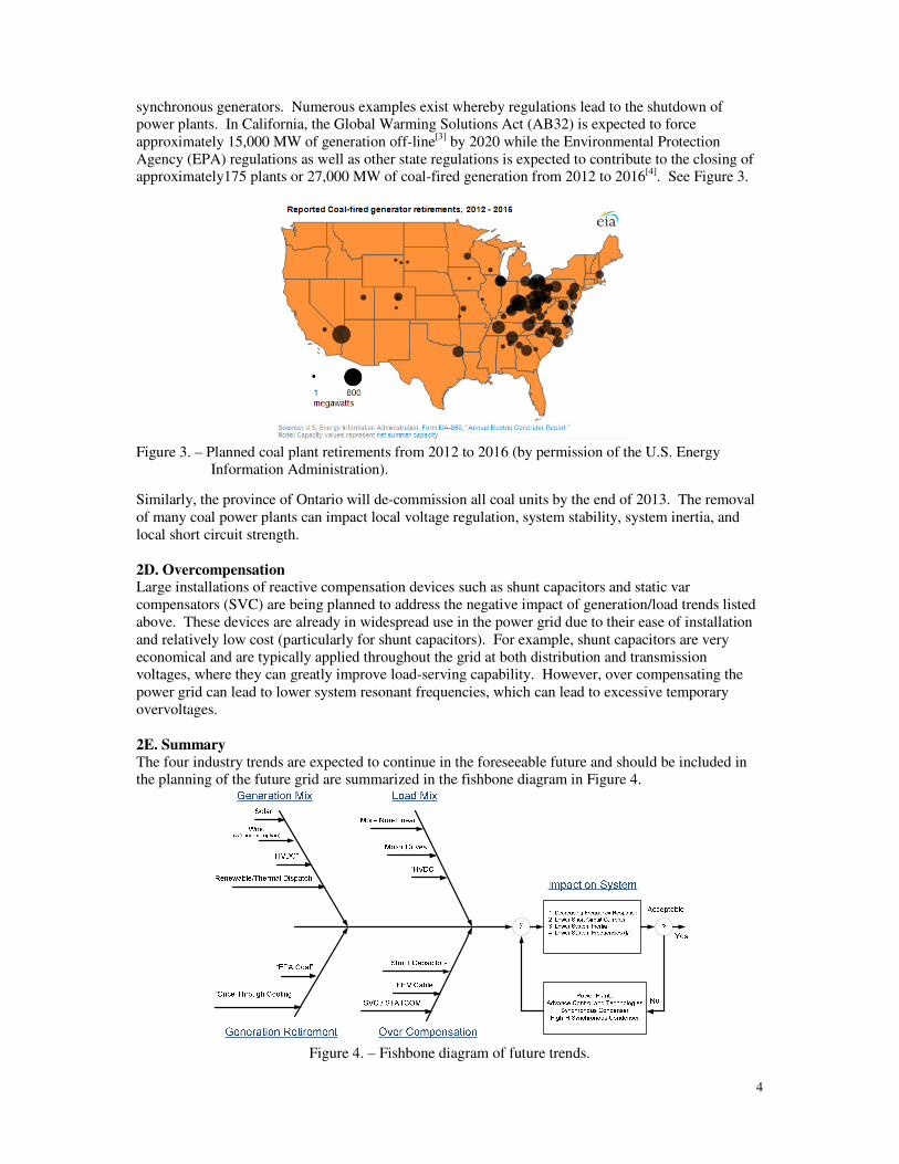
synchronous generators. Numerous examples exist whereby regulations lead to the shutdown of
power plants. In California, the Global Warming Solutions Act (AB32) is expected to force
approximately 15,000 MW of generation off-line[3]
by 2020 while the Environmental Protection
Agency (EPA) regulations as well as other state regulations is expected to contribute to the closing of
approximately175 plants or 27,000 MW of coal-fired generation from 2012 to 2016[4]. See Figure 3.
Figure 3. – Planned coal plant retirements from 2012 to 2016 (by permission of the U.S. Energy
Information Administration).
Similarly, the province of Ontario will de-commission all coal units by the end of 2013. The removal
of many coal power plants can impact local voltage regulation, system stability, system inertia, and
local short circuit strength.
2D. Overcompensation Large installations of reactive compensation devices such as shunt capacitors and static var
compensators (SVC) are being planned to address the negative impact of generation/load trends listed
above. These devices are already in widespread use in the power grid due to their ease of installation
and relatively low cost (particularly for shunt capacitors). For example, shunt capacitors are very
economical and are typically applied throughout the grid at both distribution and transmission
voltages, where they can greatly improve load-serving capability. However, over compensating the
power grid can lead to lower system resonant frequencies, which can lead to excessive temporary
overvoltages.
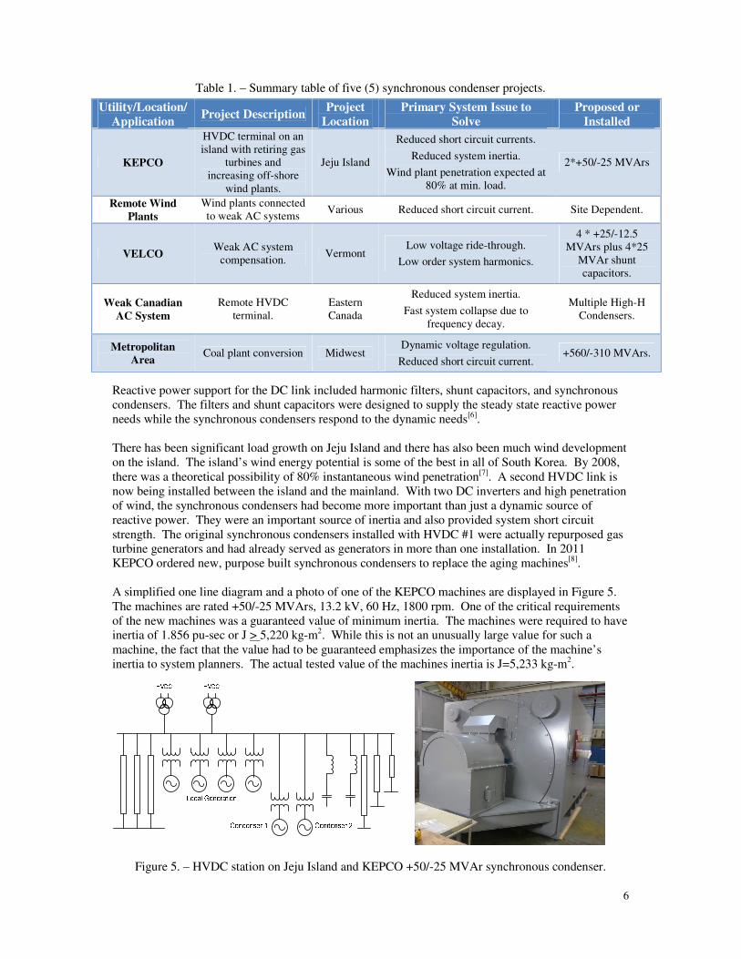
2E. Summary
The four industry trends are expected to continue in the foreseeable future and should be included in
the planning of the future grid are summarized in the fishbone diagram in Figure 4.
Figure 4. – Fishbone diagram of future trends.

5
The fishbone diagram relates contributing factors to expected outcomes. In Figure 4, there are four
main industry trends (i.e.: Generation Mix, Load Mix, Generation Retirement, and Over
Compensation) represented by the diagonal lines. Arrows labelled as contributing factors to each
industry trend are also displayed. Thus, “Solar”, “Wind”, “HVDC” and “Renewable/Thermal
Dispatch” are contributing to changes in the Generation Mix. The impact of the four industry trends
are in the box labelled “Impact on System” which have to be evaluated in the planning process and
deemed either acceptable or not. Since this diagram is a high-level simplified figure, guidance cannot
be provided here relative to acceptable or not acceptable performance because the evaluation is
location and system dependent. In the event of unacceptable performance, several options are
indicated in the feedback box which represents one or more possible mitigating options. The options
include:
Power Plants
Most of the system impacts in Figure 4 can be negated with new power plants. They provide voltage
regulation, short circuit currents, passive inertial response (or balancing inertia power), as well as
active frequency response via governor control. Unfortunately, this option can be difficult and
expensive to implement.
Advanced Control and Technologies
Advanced control and technologies include numerous options which would have to be implemented in
combination in more than one part of the transmission grid including: frequency response, high-speed
energy storage, modification of power plant and/or turbine controls. Demand response involves
reducing load demand during severe system disturbances in order to avoid under frequency load
shedding schemes. Fast acting energy storage has the ability to provide short term power to the grid
during severe system disturbances to avoid under frequency load tripping. Modification of power
plant and turbine controls involve modification of power plants to respond to grid frequency
deviations via governor control instead of operating at a constant MW setting[5]. In general, advanced
controls and technologies are implemented among many stakeholders and the incentives to provide
these services may not be clear.
Synchronous Condensers
Synchronous condensers are unloaded synchronous machines connected to the transmission grid via
step-up transformers and are not only able to regulate voltage and have excellent fault-ride through
capability, but also provide short circuit current and passive inertial response. The latter two
characteristics can help mitigate system impacts of the four identified industry trends.
High-Inertia Synchronous Condensers
Synchronous condensers with high- inertia capability are similar to traditional synchronous condensers
but have additional inertia obtained either by de-rating the nameplate rating of a given condenser or
adding a flywheel. Traditional condensers have inertia constants around two (2) while H values in the
range of 4 to 6 and greater are possible with flywheels. High-inertia (high-H) condensers have inertia
constants similar to conventional power plants.
The next section outlines five transmission projects incorporating synchronous condensers.
3. TRANSMISSION PROJECTS ENABLED WITH SYNCHRONOUS
CONDENSERS 3A. Background
Several transmission projects that utilize synchronous condensers are summarized in Table 1.
3B. KEPCO Jeju Island is located about 100 km south of the Korean peninsula and is a popular South Korean
vacation destination. The island is served by Korean Electric Power Company (KEPCO), which is the
electric utility company for South Korea. Since 1998 an HVDC link has provided an electrical
connection between the island and the mainland. Although local generation on the island existed, the
DC link was set up with the ability to operate as the sole source of electric power for the island.
6
Table 1. – Summary table of five (5) synchronous condenser projects.
Utility/Location/
Application Project Description
Project
Location
Primary System Issue to
Solve
Proposed or
Installed
KEPCO
HVDC terminal on an
island with retiring gas
turbines and
increasing off-shore
wind plants.
Jeju Island
Reduced short circuit currents.
Reduced system inertia.
Wind plant penetration expected at
80% at min. load.
2*+50/-25 MVArs
Remote Wind
Plants
Wind plants connected
to weak AC systems Various Reduced short circuit current. Site Dependent.
VELCO Weak AC system
compensation. Vermont
Low voltage ride-through.
Low order system harmonics.
4 * +25/-12.5
MVArs plus 4*25
MVAr shunt
capacitors.
Weak Canadian
AC System
Remote HVDC
terminal.
Eastern
Canada
Reduced system inertia.
Fast system collapse due to
frequency decay.
Multiple High-H
Condensers.
Metropolitan
Area Coal plant conversion Midwest
Dynamic voltage regulation.
Reduced short circuit current. +560/-310 MVArs.
Reactive power support for the DC link included harmonic filters, shunt capacitors, and synchronous
condensers. The filters and shunt capacitors were designed to supply the steady state reactive power
needs while the synchronous condensers respond to the dynamic needs[6].
There has been significant load growth on Jeju Island and there has also been much wind development
on the island. The island’s wind energy potential is some of the best in all of South Korea. By 2008,
there was a theoretical possibility of 80% instantaneous wind penetration[7]
. A second HVDC link is
now being installed between the island and the mainland. With two DC inverters and high penetration
of wind, the synchronous condensers had become more important than just a dynamic source of
reactive power. They were an important source of inertia and also provided system short circuit
strength. The original synchronous condensers installed with HVDC #1 were actually repurposed gas
turbine generators and had already served as generators in more than one installation. In 2011
KEPCO ordered new, purpose built synchronous condensers to replace the aging machines[8]
.
A simplified one line diagram and a photo of one of the KEPCO machines are displayed in Figure 5.
The machines are rated +50/-25 MVArs, 13.2 kV, 60 Hz, 1800 rpm. One of the critical requirements
of the new machines was a guaranteed value of minimum inertia. The machines were required to have
inertia of 1.856 pu-sec or J > 5,220 kg-m2. While this is not an unusually large value for such a
machine, the fact that the value had to be guaranteed emphasizes the importance of the machine’s
inertia to system planners. The actual tested value of the machines inertia is J=5,233 kg-m2.
Figure 5. – HVDC station on Jeju Island and KEPCO +50/-25 MVAr synchronous condenser.

7
3C. Remote Wind Plants Wind plants are often located in remote areas such that the existing transmission grid is not very
robust and the short circuit current at the wind plant is below the acceptable value as determined by
the short circuit ratio (SCR). The SCR is defined by the short circuit MVA at the Point of
Interconnection (POI) or the wind plant collector bus to the wind plant MW as determined by the
potential wind plant equipment supplier. In equation form:
SCR = MVA / MW
where the minimum SCR will be wind plant vendor dependent. When the calculated SCR is below the
nominal value, there are several options including: 1) increase the available short circuit current at the
wind plant via transmission grid enhancements, 2) decrease the MW rating of the wind plant, or 3)
both.
Transmission enhancements can include additional transmission lines, transformers, or a combination.
An alternate approach is to apply synchronous condenser(s) at the wind plant station to increase the
local short circuit MVA to enable the installation of the planned wind plant.
A representative application is displayed in Figures 6A and 6B of a wind plant connected to a weak
AC grid. In order to increase the SCR, the synchronous condenser is a potential solution. Several
wind plants in the planning stage are incorporating synchronous condensers. Figure 6C provides a
simplified way of estimating the rating of the condenser versus the amount of improvement in SCR
(∆SCR) required at the wind plant collector bus.
Figure 6A. – Synchronous condenser connected to the main wind plant transformer.
Figure 6B. – Synchronous condenser connected to a dedicated transformer.
Figure 6C. – Approximate synchronous condenser overexcited rating in p.u. of wind plant MW rating
versus the SCR improvement (∆SCR) desired at the collector bus for Figure 6B.
To illustrate, if the SCR at the collector bus is required to increase from X to X+1, the approximate
synchronous condenser overexcited rating in p.u. of wind plant MW rating will vary between 0.167
Synchronous
condenser
overexcited
rating in per
unit of wind
plant MW
rating.
SCR Improvement (∆SCR) Required.
8
p.u. to 0.25 p.u. of MW wind plant rating as affected by the sum of the condenser and transformer
impedances. Thus, in the case of a 75 MW wind plant with the original SCR of X without the
condenser whereby the SCR needs to be increased to X+1 (∆SCR=1), the overexcited rating of the
condenser will vary between 0.167 and 0.25 p.u. of 75 MW. In this case, 12.5 MVArs to 18.8 MVArs
is the estimated condenser overexcited rating, depending on the synchronous condenser X”d and
transformer Xt. The condenser rating is lower when these impedances are minimized.
The known installation of synchronous condensers at wind plants now includes several countries
including the United States, Canada, and Australia.
3D. VELCO VELCO was experiencing significant load growth in the early 2000’s. During peak load conditions,
up to 90% of the power was imported from sources outside the state. This situation resulted in voltage
stability concerns, especially at key locations such as the Granite Substation. During worst case
contingencies, up to 180 MVAr of local reactive power was needed at Granite. Various technologies
were investigated as possible sources of this reactive power, including mechanically switched
capacitors, SVC, STATCOM and synchronous condensers. Combinations of devices used in a hybrid
solution were also considered. One particular requirement for the device at Granite was low voltage
ride-through. The key cases studied indicated that voltage instability was the primary reason for
needing a reactive power device at Granite[9].
The performance of various reactive power devices under low voltage condition is not always similar.
Reference [10] provides a particularly helpful comparison of the performance of SVC and STATCOM
under low voltage conditions. As this source is focused particularly on FACTS devices it does not
mention the traditional machine based synchronous condenser. The V-I and V-Q curves seen in
Reference [10] provide a helpful method of comparing expected output of different devices under low
voltage conditions. By contrast, synchronous condenser manufacturers traditionally provide a “V”
curve to illustrate performance characteristics. In order to facilitate performance comparison, the V-I
and V-Q curves of a synchronous condenser are needed. This curve depends on the length of time of
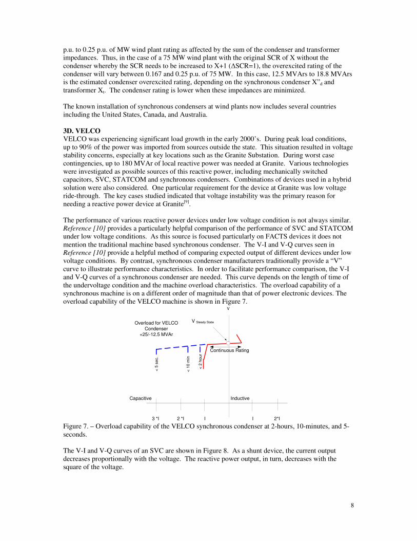
the undervoltage condition and the machine overload characteristics. The overload capability of a
synchronous machine is on a different order of magnitude than that of power electronic devices. The
overload capability of the VELCO machine is shown in Figure 7.
InductiveCapacitive
V
Continuous Rating
3 *I
V Steady State
< 5
se
c.
< 1
0 m
in
< 2
hou
r
2 *I I I
Overload for VELCO
Condenser
+25/-12.5 MVAr
2*I Figure 7. – Overload capability of the VELCO synchronous condenser at 2-hours, 10-minutes, and 5-
seconds.
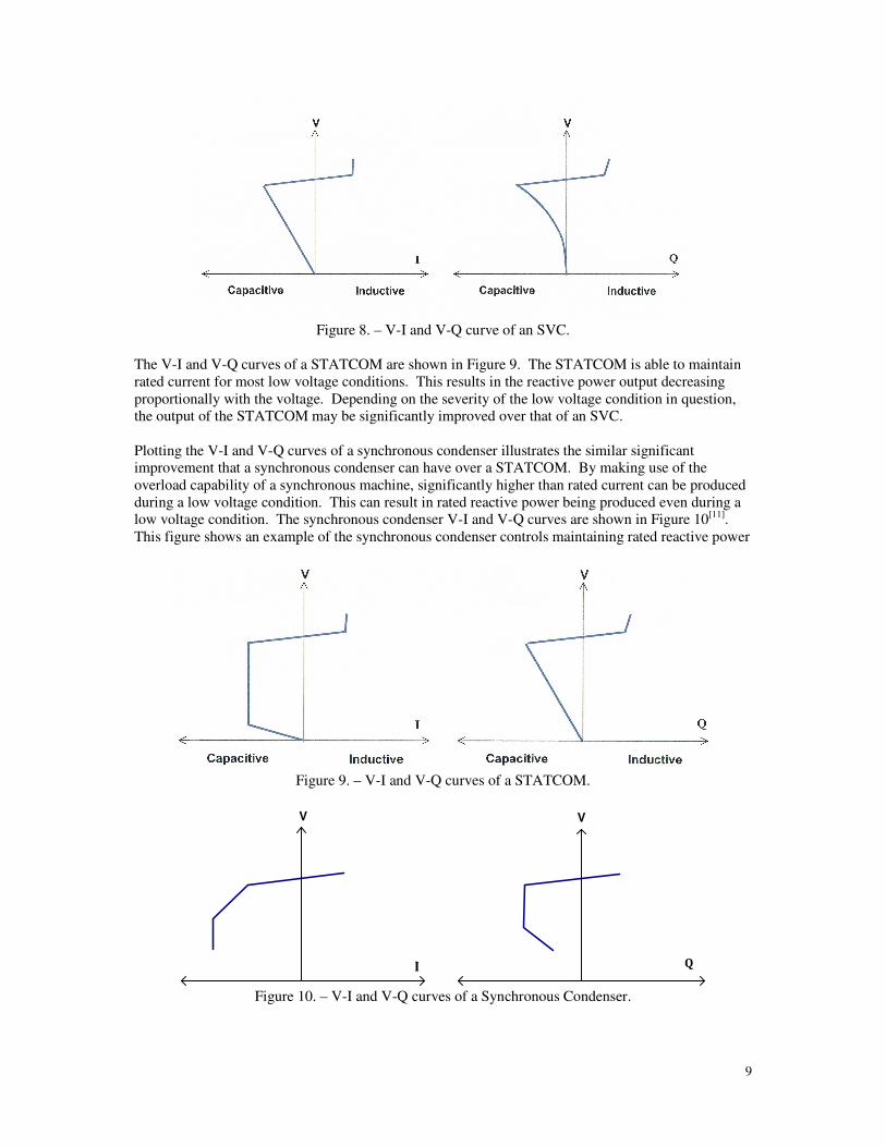
The V-I and V-Q curves of an SVC are shown in Figure 8. As a shunt device, the current output
decreases proportionally with the voltage. The reactive power output, in turn, decreases with the
square of the voltage.
9
Figure 8. – V-I and V-Q curve of an SVC.
The V-I and V-Q curves of a STATCOM are shown in Figure 9. The STATCOM is able to maintain
rated current for most low voltage conditions. This results in the reactive power output decreasing
proportionally with the voltage. Depending on the severity of the low voltage condition in question,
the output of the STATCOM may be significantly improved over that of an SVC.
Plotting the V-I and V-Q curves of a synchronous condenser illustrates the similar significant
improvement that a synchronous condenser can have over a STATCOM. By making use of the
overload capability of a synchronous machine, significantly higher than rated current can be produced
during a low voltage condition. This can result in rated reactive power being produced even during a
low voltage condition. The synchronous condenser V-I and V-Q curves are shown in Figure 10[11].
This figure shows an example of the synchronous condenser controls maintaining rated reactive power
Figure 9. – V-I and V-Q curves of a STATCOM.
V V
I Q
Figure 10. – V-I and V-Q curves of a Synchronous Condenser.

10
output during a low voltage condition. This is achieved by allowing current above nameplate rating.
At some point a limit in the capability of the machine will be reached and the reactive power output
will begin to taper off. This performance difference can be significant in some applications.
In addition to the four 25 MVAr machines at VELCO, there are four mechanically switched 25 MVAr
shunt capacitor banks. In a dynamic situation, a machine can react quickly to the needs of the station.
A capacitor bank can then be switched in or out, freeing the machine to respond to further dynamic
needs. A Joint Var Controller is used to coordinate the output of the machines and the capacitor
banks.
In addition to the machine performance at low voltage, the performance in a relatively weak power
system was also important to VELCO. A low-order harmonic resonance was known to exist in the
area. It was desired to add a dynamic reactive power device which would not exacerbate this
situation[12]. Both SVC and STATCOM technologies have the potential to produce harmonics. A
synchronous condenser is essentially harmonic-free and it can also act as a sink for harmonics in the
area. Use of a synchronous condenser in the presence of low-order system harmonics was not a major
concern[9].
3E. Weak Canadian AC System Lower Churchill is a large hydroelectric development project in the Canadian province of
Newfoundland and Labrador. Related to this development, public report WTO DC1020 – HVdc
Sensitivity Studies[13] was prepared. This report recommends the use of high- inertia (H=7.84)
synchronous condensers in order to obtain suitable system performance. High-inertia synchronous
condensers are recommended in order to reduce the size or number of condensers required for the
installation as well as preventing system collapse due to frequency decay.
High-inertia synchronous condensers can be attained either by de-rating the nameplate of a given
synchronous condenser or increasing the spinning mass of the machine with the addition of a flywheel.
Both methods for increasing the inertia are evident in the following equation:
H = ½ J ω02 / VAbase
where H is inertia constant, J is the moment of inertia of the condenser rotor, ω0 is the angular speed in
radians/second, and VAbase is the nameplate rating of the machine.
The inertia constant is directly proportional to machine inertia and also directly proportional to the
square of machine speed. Therefore, for a specified machine MVA rating, a doubling of machine
speed will reduce by a factor of four the inertia required to arrive at an equivalent inertia constant
value. Higher speed machines will tend to be smaller in physical size for a specified electrical rating.
To achieve an inertia constant significantly higher than that inherent to a machine sized only for the
electrical rating, oversizing the machine is likely to be a more costly approach than considering the use
of a flywheel. Depending on the speed of the machine, the flywheel geometry will change subject to
mechanical stress and possibly rotational dynamic limitations. Additionally, as the flywheel inertia
increases, the ability of the synchronous condenser to be self-starting also needs to be considered and
it may become necessary to employ power electronics for this purpose. A four-pole 50 MVAr
condenser design based on synchronous motor technology will have an inherent inertia constant of
approximately two. When connected to a separately supported external flywheel having an inertia
constant of four, an overall factor of six is achieved. This flywheel inertia is similar to the connected
load inertia of a large synchronous motor of this same MVA rating driving a high speed centrifugal
compressor. Even higher H values are possible although as the machine MVAr rating increases, the
practically achievable inertia constant will decrease due to flywheel physical limitations.
The addition of the flywheel increases the numerator in the equation above while de-rating the
condenser decreases the denominator. For example, a condenser rated +50 MVArs with an H =2, can

11
be re-rated as a +25 MVAr condenser with H=4. Similarly, the addition of a flywheel on a +50 MVAr
which doubles the kinetic energy of the machine results in a condenser rated +50 MVArs with H=4.
A sketch of a high-inertia synchronous condenser is displayed in Figure 11.
Figure 11. – High-inertia synchronous condenser.
3F. Coal Plant Conversion Numerous large coal plants operate near large metropolitan areas. One particular region has a mix of
residential, commercial, and heavy industrial loads. Traditionally, this load has been served by local
generation and power imported from other large power plants. A critical measure of this system's
health at any given time is the amount of dynamic reactive power reserves from the local generation.
A minimum amount of dynamic reactive reserves is needed to maintain system voltages following the
loss of a major generation or transmission facility. This in turn requires a minimum amount of local
generation to be committed at all times.
The announcement of significant generation retirements in this area threatened to reduce the available
reactive resources below the critical level. Installing additional shunt capacitors was not an option, as
the system is already heavily compensated and shunt capacitors do not provide dynamic reactive
power. Converting two of the retired units to synchronous condensers proved to be the most robust
and cost effective solution to address the reactive power issue.
The first unit, rated at 756 MVA, has been converted to synchronous condenser duty with a capacity
of +560/-310 MVAr. The second unit, originally rated at about 300 MVA will follow. Their steam
turbines and balance of plant are being retired.
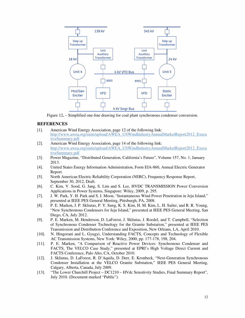
Figure 12 shows a simplified arrangement of the two units once both have been converted. The
excitation systems can inject excitation current at zero speed before the machines are accelerated to
synchronous speed using variable frequency drives (VFD). The Unit A excitation system is a new
static exciter to replace the original rotating exciter. The Unit B exciter is the original motor/generator
exciter. Both have state of the art digital controls. The accelerating power for a unit comes from the
VFDs through a back feed of its existing unit auxiliary transformers. The VFDs will be cross-
connected so that either VFD can start either unit. This arrangement is extendable in the event the
remaining other units in the plant are converted to synchronous condensers.
4. SUMMARY AND CONCLUSIONS The five transmission projects presented in this paper that were enabled with synchronous condensers
demonstrate the diverse system issues that can be solved by the inherent characteristics of synchronous
condensers. These characteristics include short circuit contribution, system inertia, robust fault ride-
through capability, and the ability to provide voltage stability via step-less voltage regulation while
offsetting the impact of generation retirements through the conversion process. Synchronous
condensers will be required in the future grid just as, if not more, than when synchronous condensers
were first applied to the transmission grid in the early part of the 20th century.
12
Unit 4 Unit 5
Step upTransformer
Step upTransformer
UnitAuxiliary
Transformer
UnitAuxiliary
Transformer
VFDStaticExciter
VFDMot/GenExciter
4 kV Swgr Bus
4 kV VFD Bus
89SS 89SS
138 kV 345 kV
18 kV 24 kV
Figure 12. – Simplified one-line drawing for coal plant synchronous condenser conversion.
REFERENCES
[1]. American Wind Energy Association, page 12 of the following link: http://www.awea.org/suite/upload/AWEA_USWindIndustryAnnualMarketReport2012_ExecutiveSummary.pdf.
[2]. American Wind Energy Association, page 14 of the following link:
http://www.awea.org/suite/upload/AWEA_USWindIndustryAnnualMarketReport2012_Execu
tiveSummary.pdf.
[3]. Power Magazine, “Distributed Generation, California’s Future”, Volume 157, No. 1, January
2013.
[4]. United States Energy Information Administration, Form EIA-860, Annual Electric Generator
Report.
[5]. North American Electric Reliability Corporation (NERC), Frequency Response Report,
September 30, 2012, Draft.
[6]. C. Kim, V. Sood, G. Jang, S. Lim and S. Lee, HVDC TRANSMISSION Power Conversion
Applications in Power Systems, Singapore: Wiley, 2009, p. 295.
[7]. J. W. Park, Y. H. Park and S. I. Moon, “Instantaneous Wind Power Penetration in Jeju Island,”
presented at IEEE PES General Meeting, Pittsburgh, PA, 2008.
[8]. P. E. Marken, J. P. Skliutas, P. Y. Sung, K. S. Kim, H. M. Kim, L. H. Sailer, and R. R. Young,
“New Synchronous Condensers for Jeju Island,” presented at IEEE PES General Meeting, San
Diego, CA, July 2012.
[9]. P. E. Marken, M. Henderson, D. LaForest, J. Skliutas, J. Roedel, and T. Campbell, “Selection
of Synchronous Condenser Technology for the Granite Substation,” presented at IEEE PES
Transmission and Distribution Conference and Exposition, New Orleans, LA, April 2010.
[10]. N. Hingorani and L. Gyugyi, Understanding FACTS, Concepts and Technology of Flexible
AC Transmission Systems, New York: Wiley, 2000, pp. 177-178, 198, 204.
[11]. P. E. Marken, “A Comparison of Reactive Power Devices: Synchronous Condenser and
FACTS, The VELCO Case Study,” presented at EPRI’s High Voltage Direct Current and
FACTS Conference, Palo Alto, CA, October 2010.
[12]. J. Skliutas, D. LaForest, R. D’Aquila, D. Derr, E. Kronbeck, “Next-Generation Synchronous
Condenser Installation at the VELCO Granite Substation,” IEEE PES General Meeting,
Calgary, Alberta, Canada, July 2009.
[13]. “The Lower Churchill Project – DC1210 – HVdc Sensitivity Studies, Final Summary Report”,
July 2010. (Document marked “Public”).