chuck stancil -...
TRANSCRIPT

Copyright © 2004, PCI-SIG, All Rights Reserved 1
PCI ExpressTM Form Factors:Card, Mini Card and ExpressCard*
PCI ExpressTM Form Factors:Card, Mini Card and ExpressCard*
Chuck StancilHewlett-Packard Company
Chair, PCI Express Electromechanical WG
Chuck StancilHewlett-Packard Company
Chair, PCI Express Electromechanical WG

Copyright © 2004, PCI-SIG, All Rights Reserved 2PCI-SIG APAC Developers Conference
AgendaAgenda§ Add-in CardüReview of add-in card basicsüWhat’s new since the CEM 1.0a spec was released?
§ PCI Express Mini CardüReview of basicsüWhat’s new
§ ExpressCard* § Summary§ Call to Action
* Other names and brands may be claimed as the property of other* Other names and brands may be claimed as the property of others. s.
Copyright © 2004, PCI-SIG, All Rights Reserved 3PCI-SIG APAC Developers Conference
Add-in Card

Copyright © 2004, PCI-SIG, All Rights Reserved 4PCI-SIG APAC Developers Conference
PCI Express Is Optimized for CostPCI Express Is Optimized for Cost
Standard Height Cards, 4.20” (106.7mm)
Low Profile Cards, 2.536” (64.4mm)
Half Length Cards, 6.6” (167.65mm)
Full Length Cards, 12.283” (312mm)
Uses PCI I/O Bracket
Follows PCI Card form factors
Simple Add-in Card DesignSimple Add-in Card Design

Copyright © 2004, PCI-SIG, All Rights Reserved 5PCI-SIG APAC Developers Conference
Add-in Card Size ExceptionsAdd-in Card Size Exceptions§ Standard height x1 cards are limited to half-
length (6.6”) for desktop applicationsüPush towards small form factor systemsü10W power limit
§ For server I/O needs there is allowance fora 25W, standard height x1 card that MUSTbe greater or equal to 7.0” but less than or equal to full length

Copyright © 2004, PCI-SIG, All Rights Reserved 6PCI-SIG APAC Developers Conference
x1 connector 36 pins vs.PCI 120 pins
Simple Single Level Contacts
1mm Contact Spacing
Low Cost Connector Assembly
Low Cost Edge Card ConnectorLow Cost Edge Card Connector

Copyright © 2004, PCI-SIG, All Rights Reserved 7PCI-SIG APAC Developers Conference
x1x4
x8
Scalable Design allows connectors from x1 to x16 to be easily designed
Smaller link-width cards can plug into larger link-width connectors
Use same contacts
Modular body design
Use same connector manufacturing process
x16
Scalable Connector DesignScalable Connector Design

Copyright © 2004, PCI-SIG, All Rights Reserved 8PCI-SIG APAC Developers Conference
X1 PCI Express
x16 PCI Express Graphics
I/O Connectors
PCI
Slot Placement StrategySlot Placement Strategy

Copyright © 2004, PCI-SIG, All Rights Reserved 9PCI-SIG APAC Developers Conference
PCI Express layout and connectors can be routedin 4 Layers
PCI Express x16 connector(64 times PCI performance)
µATX 4 Layer, P4 Motherboard
PCI Connectors
Flexibility in routing PCI Express and PCI connectors on thesame board
PCI Express x1 connector(4 times PCI performance)
Smaller connectors provide more room for routing and components
Routing in 4-Layer MotherboardsRouting in 4-Layer Motherboards

Copyright © 2004, PCI-SIG, All Rights Reserved 10PCI-SIG APAC Developers Conference
375mA max375mA max375mA max+3.3Vaux ±9%
5.5A max2.1A max0.5A max+12V ±8%
3A max3A max3A max+3.3V ±9%
75W slot25W slot10W slotPower Rail
Compared to PCI and AGP: § Additional power from 12v rail
§ +5V, -12V requirements are eliminated
Notes:§ 3.3Vaux max current is 375mA when the add-in card
is Wake enabled and 20mA when Wake disabled.§ An ECR to the CEM 1.0 spec changed the maximum slot
power from 60W to 75W
Power DeliveryPower Delivery
Copyright © 2004, PCI-SIG, All Rights Reserved 11PCI-SIG APAC Developers Conference
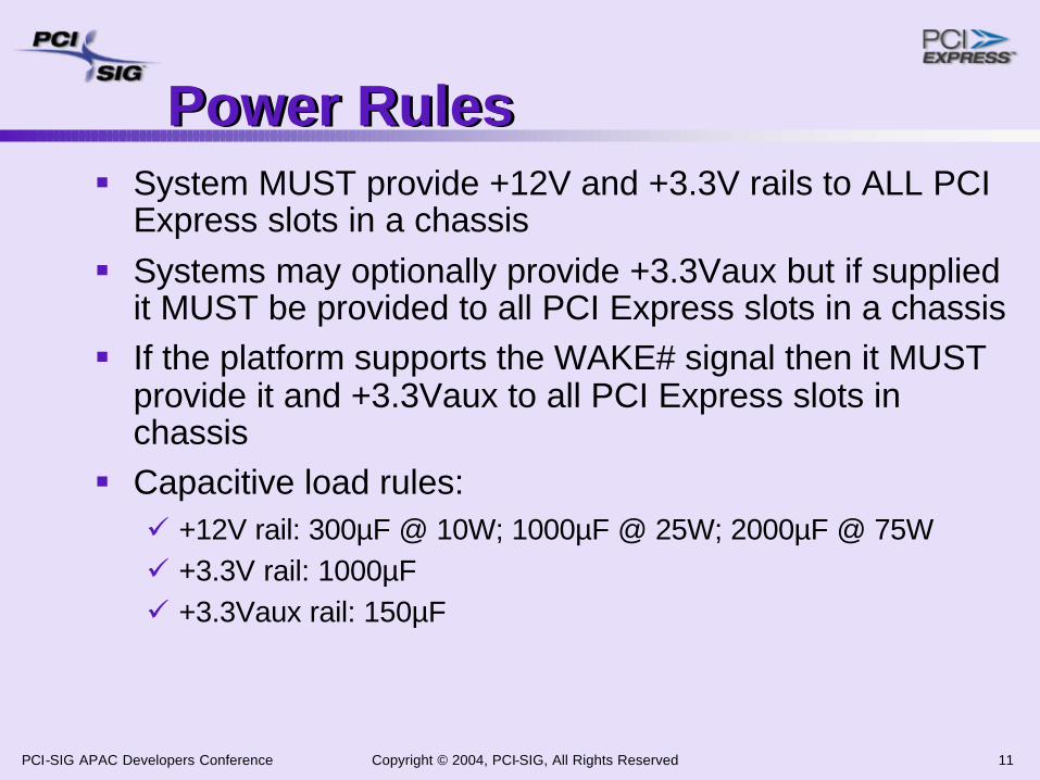
Power RulesPower Rules§ System MUST provide +12V and +3.3V rails to ALL PCI
Express slots in a chassis§ Systems may optionally provide +3.3Vaux but if supplied
it MUST be provided to all PCI Express slots in a chassis§ If the platform supports the WAKE# signal then it MUST
provide it and +3.3Vaux to all PCI Express slots in chassis
§ Capacitive load rules:ü +12V rail: 300µF @ 10W; 1000µF @ 25W; 2000µF @ 75Wü +3.3V rail: 1000µFü +3.3Vaux rail: 150µF
Copyright © 2004, PCI-SIG, All Rights Reserved 12PCI-SIG APAC Developers Conference
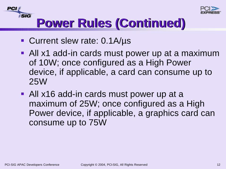
Power Rules (Continued)Power Rules (Continued)§ Current slew rate: 0.1A/µs§ All x1 add-in cards must power up at a maximum
of 10W; once configured as a High Power device, if applicable, a card can consume up to 25W § All x16 add-in cards must power up at a
maximum of 25W; once configured as a High Power device, if applicable, a graphics card can consume up to 75W

Copyright © 2004, PCI-SIG, All Rights Reserved 13PCI-SIG APAC Developers Conference
Power & Card SummaryPower & Card Summary§ 10W: x1 cards (= 6.6” length)§ 25W: x1 cards (> 7.0” length), x4 cards, x8
cards, x16 low-profile graphics cards, x16 server I/O cards§ 75W: x16 full-height graphics cards

Copyright © 2004, PCI-SIG, All Rights Reserved 14PCI-SIG APAC Developers Conference
RequiredNoNoNox16
AllowedRequiredNoNox8
AllowedAllowedRequiredNox4
RequiredRequiredRequiredRequiredx1
x16x8x4x1SlotCard
Add-in Card InteroperabilityAdd-in Card Interoperability
§ Up-plugging: Plugging a smaller link card into a larger link connector is fully allowed.
§ Down-plugging: Plugging a larger link card into a smaller link connector is not allowed and is physically prevented.
§ Down-shifting: Plugging a card into a connector that is not fully routed for all of the lanes. In general, this is not allowed. The exception is the x8 connector which the system designer may choose to route only the first four lanes. A x8 card functions as a x4 card in this scenario.

Copyright © 2004, PCI-SIG, All Rights Reserved 15PCI-SIG APAC Developers Conference
Reference Clock(REFCLK+, REFCLK-)Reference Clock(REFCLK+, REFCLK-)
§ Differential pair § Nominal frequency of 100MHz (±300ppm)§ Point-to-point connection between each PCI
Express connector and the clock source§ Within each differential pair the PCB trace
lengths must be within 0.005Ӥ Spread Spectrum support is optional but likely
needed to pass emissions testing!§ Termination resistors located at the clock source
Copyright © 2004, PCI-SIG, All Rights Reserved 16PCI-SIG APAC Developers Conference
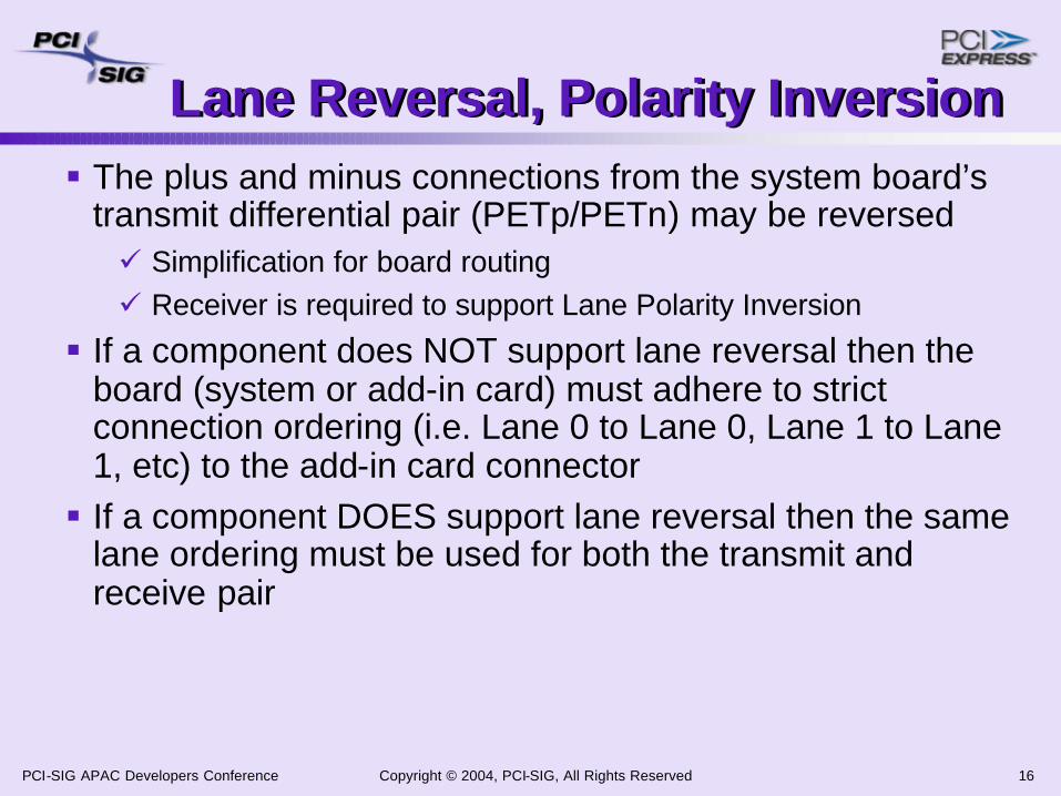
Lane Reversal, Polarity InversionLane Reversal, Polarity Inversion§ The plus and minus connections from the system board’s
transmit differential pair (PETp/PETn) may be reversedü Simplification for board routingü Receiver is required to support Lane Polarity Inversion
§ If a component does NOT support lane reversal then the board (system or add-in card) must adhere to strict connection ordering (i.e. Lane 0 to Lane 0, Lane 1 to Lane 1, etc) to the add-in card connector§ If a component DOES support lane reversal then the same
lane ordering must be used for both the transmit and receive pair

Copyright © 2004, PCI-SIG, All Rights Reserved 17PCI-SIG APAC Developers Conference
CEM spec updates since Revision 1.0aCEM spec updates since Revision 1.0a
§ Card Presence Detect§ REFCLK clarification§ Slot Power Limit Implementation Note§ Connector color§ Card retention§ PERST# clarification

Copyright © 2004, PCI-SIG, All Rights Reserved 18PCI-SIG APAC Developers Conference
Card Presence DetectCard Presence Detect§ Supports the hot plug solution; ALL add-in cards must implement
both gold fingers, PRSNT1# and the “furthest” PRSNT2#§ System use is optional for non-hot plug solutions§ There are multiple PRSNT2# pins on the connector – this is needed
to support up-pluggingü System buses them togetherü Add-in card connects PRSNT1# to the FURTHEST PRSNT2#
pin on its connector
PULL-UP
BASEBOARD
PCI Express CARD
MATE LAST/BREAK FIRST
45º
Trace on the add-in card(actual trace routing is left up to the board designer)
Baseboard Connector
PRSNT1# PRSNT2#
Gold fingers
To logic onboard
Hot plug controller
Copyright © 2004, PCI-SIG, All Rights Reserved 19PCI-SIG APAC Developers Conference
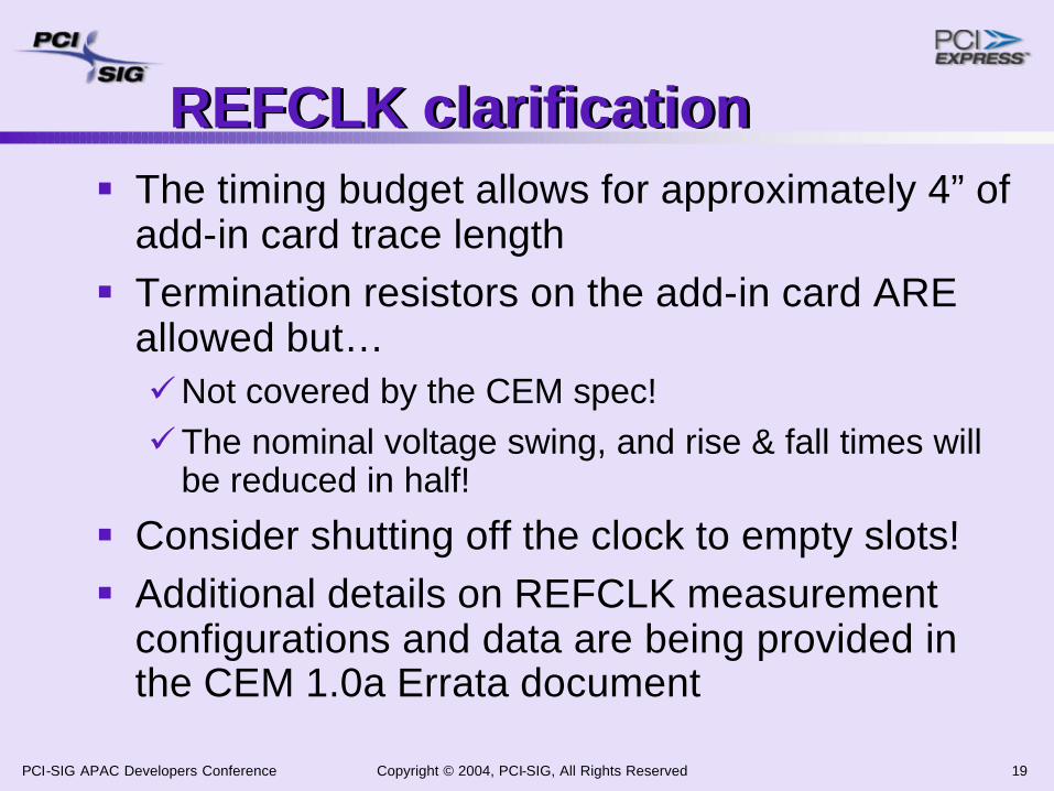
REFCLK clarificationREFCLK clarification§ The timing budget allows for approximately 4” of
add-in card trace length§ Termination resistors on the add-in card ARE
allowed but…üNot covered by the CEM spec!üThe nominal voltage swing, and rise & fall times will
be reduced in half!
§ Consider shutting off the clock to empty slots!§ Additional details on REFCLK measurement
configurations and data are being provided in the CEM 1.0a Errata document

Copyright © 2004, PCI-SIG, All Rights Reserved 20PCI-SIG APAC Developers Conference
Slot Power Implementation NoteSlot Power Implementation Note§ Software Update of the Slot Power Limit -
System firmware must update the slot power limit to the system'sallocated value for the PCI Express add-in card (e.g. Graphics) and ensure the completion of this update prior to invoking the option ROM for that add-in card's PCI Express function. If the initial slot power limit value is set by hardware initialization then any attempt by software to change that value must be verified by that software prior to initializing the add-in card. Subsequent updates by the system firmware or operating system software, if any, may only increase the slot power limit value. However, after a card is reset the initial slot power limit value may be lower than the previous value. The maximum power level for an add-in card must be assigned by the system firmware during PCI Express bus configuration. For graphics the power level assigned will be dependent on the platforms support of the PCI Express Graphics High-End Specification (including the supplemental power cable).
Copyright © 2004, PCI-SIG, All Rights Reserved 21PCI-SIG APAC Developers Conference
Connector ColorConnector Color§ CEM 1.0 did not suggest or specify a color for
the add-in card connector§ Approved ECN addresses this§ By default the recommended color should be
black üThis color hasn’t been used for an add-in card
connector since ISA was around)üAvoids any confusion with PCI connectors even
though PCI and PCI Express cards are mechanically incompatible
§ Other colors ARE allowed if a system OEM requires a particular color coding scheme

Copyright © 2004, PCI-SIG, All Rights Reserved 22PCI-SIG APAC Developers Conference
Card RetentionCard Retention§ ECN defines additional component keepout areas on
add-in cards to support system-level card retention§ Focus is on full-height, x16 cards for Graphics

Copyright © 2004, PCI-SIG, All Rights Reserved 23PCI-SIG APAC Developers Conference
PERST# ClarificationPERST# Clarification§ ECN defines threshold windows for PERST# activation§ Voltage monitoring circuitry will be able to reliably detect
a power rail condition requiring the assertion of PERST#

Copyright © 2004, PCI-SIG, All Rights Reserved 24PCI-SIG APAC Developers Conference
Add-in Card SummaryAdd-in Card Summary§ PCI Express is Optimized for CostüCost-effective for migration into commodity
infrastructureüReplaces PCI over time with 15+ years of life
§ PCI Express is Easy to ImplementüLeverages existing form factors and standardsüTransition with existing PCI form factors

Copyright © 2004, PCI-SIG, All Rights Reserved 25PCI-SIG APAC Developers Conference
PCI Express Mini Card

Copyright © 2004, PCI-SIG, All Rights Reserved 26PCI-SIG APAC Developers Conference
What is PCI Express Mini CardWhat is PCI Express Mini Card
§ Replacement for Mini PCIüTargeted for BTO/CTO solutions
§ PCI Express and USB 2.0 enabledüOptimized for communication add-ins
§ Card envelope: 30mm x 56mm x 5mmüEqual to ½ width of Mini PCI Type IIIa card

Copyright © 2004, PCI-SIG, All Rights Reserved 27PCI-SIG APAC Developers Conference
Communications CentricCommunications Centric
Copyright © 2004, PCI-SIG, All Rights Reserved 28PCI-SIG APAC Developers Conference
Targeted ApplicationsTargeted Applications§ Wireless-Personal Area Network (W-PAN)ü Bluetooth / Ultra wideband
§ Local Area Network (LAN)ü 10/100/1G/10G Ethernet
§ Wireless-LAN (W-LAN)ü 802.11b/g/a, etc.
§ Wide Area Network (WAN)ü V.90/V.92 modem / xDSL / cable modem
§ Wireless-WAN (W-WAN)ü GSM/GPRS / UMTS / CDMA

Copyright © 2004, PCI-SIG, All Rights Reserved 29PCI-SIG APAC Developers Conference
Half the Size of Mini PCIHalf the Size of Mini PCI
Mini PCI(Type IIIa)
PCI ExpressMini Card
3030
5151

Copyright © 2004, PCI-SIG, All Rights Reserved 30PCI-SIG APAC Developers Conference
Upgradeability / ServiceabilityUpgradeability / Serviceability§ Angled insertion and removal
§ OEM optimized retentionü Internal clips / screws / door
attached clip
§ BTO / CTOü Single connectorü Multiple technologies
§ Field replacement by service techniciansü Reduce TCO / services costs

Copyright © 2004, PCI-SIG, All Rights Reserved 31PCI-SIG APAC Developers Conference
Mechanical Summary (1)Mechanical Summary (1)
Card outline dimensioning
Cross-section

Copyright © 2004, PCI-SIG, All Rights Reserved 32PCI-SIG APAC Developers Conference
Mechanical Summary (2)Mechanical Summary (2)
Keep out zones
I/O connector zone
Copyright © 2004, PCI-SIG, All Rights Reserved 33PCI-SIG APAC Developers Conference
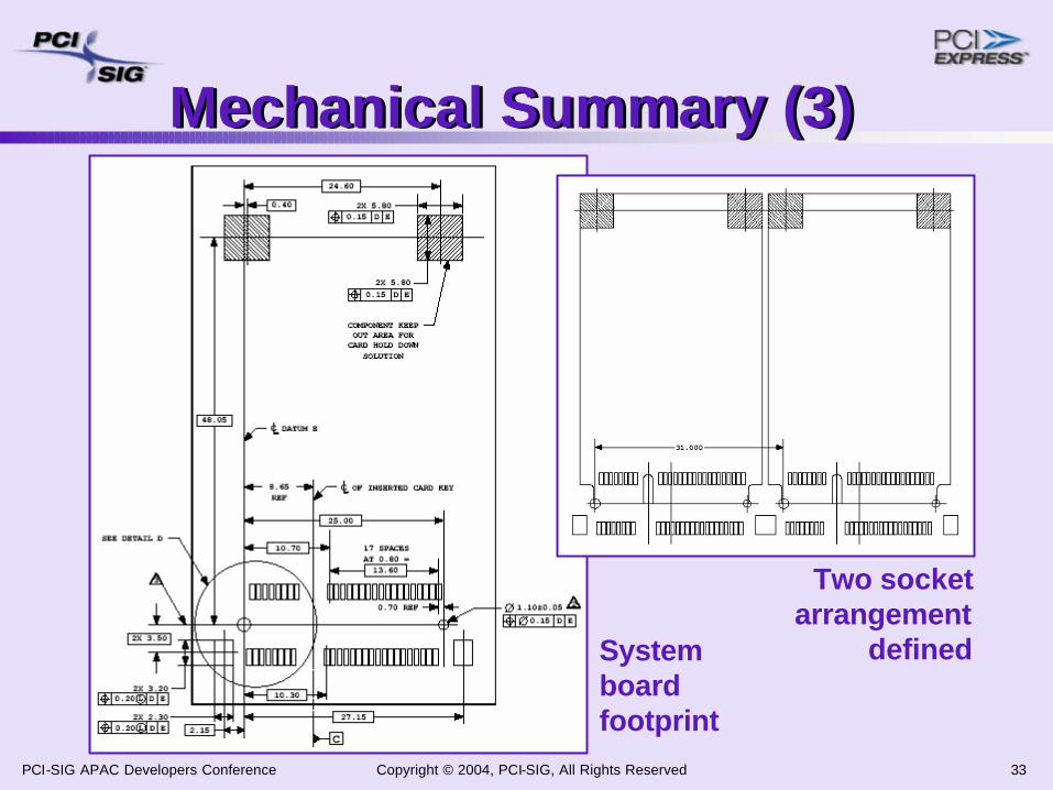
Mechanical Summary (3)Mechanical Summary (3)
Two socketarrangement
definedSystemboardfootprint

Copyright © 2004, PCI-SIG, All Rights Reserved 34PCI-SIG APAC Developers Conference
Signal SummarySignal Summary

Copyright © 2004, PCI-SIG, All Rights Reserved 35PCI-SIG APAC Developers Conference
Pin ArrangementPin Arrangement
PCIExpress
REFClock
USB
52 pin solution
Arranged toassure isolation
CLKREQ#
AUX

Copyright © 2004, PCI-SIG, All Rights Reserved 36PCI-SIG APAC Developers Conference
Power and ThermalsPower and Thermals
Power Density Uniform Loading@80% coverage
00.010.020.030.040.050.060.070.080.090.1
0.095 0.115 0.135 0.155 0.175 0.195 0.215
Top Side (W/Sq. cm)
Bot
tom
Sid
e (W
/Sq.
cm
)
Power Density Uniform Loading@80% coverage
00.010.020.030.040.050.060.070.080.090.1
0.095 0.115 0.135 0.155 0.175 0.195 0.215
Top Side (W/Sq. cm)
Bot
tom
Sid
e (W
/Sq.
cm
)
2.3W MAXthermal
dissipation
3W MAX powerconsumption
+3.3V (AUX)

Copyright © 2004, PCI-SIG, All Rights Reserved 37PCI-SIG APAC Developers Conference
Designed for Power EfficiencyDesigned for Power Efficiency§ Robust power management featuresü ACPI and PCI PM supportedü In-band wake mechanisms supportedü Wake# – enables lowest system power solutionenables lowest system power solutionü SMBus – available for advanced featuresavailable for advanced features
§ Dual power planesü 3.3V – nominal voltage required for I/O drive requirementsnominal voltage required for I/O drive requirementsü 1.5V – reduces need for onreduces need for on--card regulationcard regulation
§ Two power statesü PRIMARY – 3.3V and 1.5V fully ONü AUXILIARY – 3.3VAUX available in D3HOT

Copyright © 2004, PCI-SIG, All Rights Reserved 38PCI-SIG APAC Developers Conference
Status IndicatorsStatus Indicators§ Three LEDsüW-PANüW-LANüW-WAN
§ Single-ended,9 mA sinkcapable
§ LED support via I/O connectorüStill an option

Copyright © 2004, PCI-SIG, All Rights Reserved 39PCI-SIG APAC Developers Conference
Ease of DesignEase of Design§ Digital / Analog physical separationü RF is not as near to digital
– High speed digital on host connector– Analog on I/O connectors
§ Spread Spectrum Reference clock supportsü Reduced EMI emissions
§ Software compatibilityü Per native bus definitions
– PCI Express– USB 2.0– SMBus 2.0
ANALOG
DIGITAL
Copyright © 2004, PCI-SIG, All Rights Reserved 40PCI-SIG APAC Developers Conference
Mini Card SummaryMini Card Summary
§ Higher performance and smaller F/F replacement for Mini PCI§ Optimized for communications applicationsü IHVs can select the serial interface appropriate for
their deviceüSupport for LED status indicators
§ Outstanding power management features

Copyright © 2004, PCI-SIG, All Rights Reserved 41PCI-SIG APAC Developers Conference
ExpressCard*
* Other names and brands may be claimed as the property of other* Other names and brands may be claimed as the property of others. s.
Copyright © 2004, PCI-SIG, All Rights Reserved 42PCI-SIG APAC Developers Conference
AgendaAgenda§ The motivation behind ExpressCard
technology§ Key characteristic details of ExpressCard
technology§ Key design considerations§ ExpressCard applications opportunities

Copyright © 2004, PCI-SIG, All Rights Reserved 43PCI-SIG APAC Developers Conference
The ExpressCard* StandardThe ExpressCardExpressCard* Standard* StandardPCMCIA’s next generation PC Card technology specificationüMajor step to align with
platform trendsüRetains the best
characteristics of CardBusüLeverages advanced
serial bus technologies
* Other names and brands may be claimed as the property of other* Other names and brands may be claimed as the property of others. s.

Copyright © 2004, PCI-SIG, All Rights Reserved 44PCI-SIG APAC Developers Conference
Platform shiftspresent opportunities, drive requirementsPlatform shiftspresent opportunities, drive requirements
I/O interconnectfast serial linksnative hot-plug
Notebook PCsthinner and lighter
Desktop PCssmaller, modularform factors
Establishing module product compatibility across desktop & mobileEstablishing module product compatibility across desktop & mobilEstablishing module product compatibility across desktop & mobilee
smaller yet higher performancelower cost by design
smaller yet flexible
technology reuselower cost by volume
address growing SFF market

Copyright © 2004, PCI-SIG, All Rights Reserved 45PCI-SIG APAC Developers Conference
Desktop View on ExpressCardDesktop View on ExpressCard§ Significant ease-of-use benefit over traditional add-in cardsüClosed box I/O expansion without clutter and complexityü Lower support costs compared to traditional add-in cards
§ Uses native interfacesü I/O plumbing is “standard feature” of the base platformüNo external I/O controller or bridge is required
§ Advanced serial interfaces vs. existing parallel interfacesü Fewer pins and more bandwidthü Lower cost interconnects (connector, cables, silicon)
SFF desktop market growing – estimates range from 20% - 40% market share by 2005
SFF desktop market growing SFF desktop market growing –– estimates range estimates range from 20% from 20% -- 40% market share by 200540% market share by 2005
§ Leverage a larger combined desktop / mobile marketüDraw on mobile platform proven usage model

Copyright © 2004, PCI-SIG, All Rights Reserved 46PCI-SIG APAC Developers Conference
Architectural OverviewArchitectural Overview§ System design based on a modular, extensible slot
modelüAssumes multiple slot solutions, single slots allowed
§ Relies on native bus operationüPCI Express Base Specification 1.0aüUSB 2.0 (low / full / high speeds)
Compliant systems must support both in slots
§ Compatible with existing operating systemüFuture OS may offer non-essential enhancements

Copyright © 2004, PCI-SIG, All Rights Reserved 47PCI-SIG APAC Developers Conference
ExpressCard/34 Module Form-FactorExpressCard/34 Module Form-Factor
75 mm
34 mm
5 mm thick
top
bottom
securitynotch
finger grip
connectoralignmentfeature

Copyright © 2004, PCI-SIG, All Rights Reserved 48PCI-SIG APAC Developers Conference
ExpressCard/54 Module Form-FactorExpressCard/54 Module Form-Factor
75 mm
34 mm
5 mm thick
top54 mm
53 mm

Copyright © 2004, PCI-SIG, All Rights Reserved 49PCI-SIG APAC Developers Conference
Building a SlotBuilding a SlotSlot for 34mm modules only
Top Cover
Host ConnectorLeft Guide Rail
Right Guide Rail
Host/Daughter Card
Universal slot for both modules
Top Cover
Host ConnectorLeft Guide Rail
Right Guide Rail
PCB Insulator
Host/Daughter Card

Copyright © 2004, PCI-SIG, All Rights Reserved 50PCI-SIG APAC Developers Conference
module connectorhost connector
§ Beam-on-blade, single in-line configuration, 1mm pitchüLow-cost yet reliable and durable
– 5K / 10K cycle rating for module connectors
– 5K cycle rating for host connectors
üTwo-levels of contacts in module
blade
beam
system board
ExpressCard ConnectorsExpressCard Connectors

Copyright © 2004, PCI-SIG, All Rights Reserved 51PCI-SIG APAC Developers Conference
3.3V3.3V
3.3V3.3VAUXAUX
1.5V1.5V
PowerSwitch
System Diagram SystemSystemResetReset
RefRefCLKCLK
SMBusSMBusControllerController
ClockClockRequestRequest
WakeWakeRequestRequest
GROUND
USBD-USBD+
CPUSB#RESERVEDRESERVED
SMB_CLKSMB_DATA
+1.5V
+1.5VWAKE#
+3.3VAUX
PERST#+3.3V+3.3V
CLKREQ#CPPE#
REFCLK-
REFCLK+GROUND
PERn0
PERp0GROUND
PETn0
PETp0GROUND
121110
98
1514
7
25
242322
2120
1
23
456
13
161718
19
26
PETp0PETn0
PERp0PERn0
USBD+USBD-
HostHostChipChipSetSet

Copyright © 2004, PCI-SIG, All Rights Reserved 52PCI-SIG APAC Developers Conference
SystemSystemResetReset
WakeWakeRequestRequest
SMBusSMBusControllerController
RefRefCLKCLK
3.3V3.3V
3.3V3.3VAUXAUX
1.5V1.5V
PowerSwitch
ClockClockRequestRequest
System Diagram
PETp0PETn0
PERp0PERn0
USBD+USBD-
HostHostChipChipSetSet
GROUND
USBD-USBD+
CPUSB#RESERVEDRESERVED
SMB_CLKSMB_DATA
+1.5V
+1.5VWAKE#
+3.3VAUX
PERST#+3.3V+3.3V
CLKREQ#CPPE#
REFCLK-
REFCLK+GROUND
PERn0
PERp0GROUND
PETn0
PETp0GROUND
121110
98
1514
7
25
242322
2120
1
23
456
13
161718
19
26
ExpressCardmodule
using PCI Express
GROUND
USBD-USBD+
CPUSB#RESERVEDRESERVED
SMB_CLKSMB_DATA
+1.5V
+1.5VWAKE#
+3.3VAUX
PERST#+3.3V+3.3V
CLKREQ#CPPE#
REFCLK-
REFCLK+GROUND
PERn0
PERp0GROUND
PETn0
PETp0GROUND

Copyright © 2004, PCI-SIG, All Rights Reserved 53PCI-SIG APAC Developers Conference
SystemSystemResetReset
WakeWakeRequestRequest
SMBusSMBusControllerController
RefRefCLKCLK
3.3V3.3V
3.3V3.3VAUXAUX
1.5V1.5V
PowerSwitch
ClockClockRequestRequest
System Diagram
PETp0PETn0
PERp0PERn0
USBD+USBD-
HostHostChipChipSetSet
GROUND
USBD-USBD+
CPUSB#
RESERVEDRESERVED
SMB_CLK
SMB_DATA+1.5V+1.5V
WAKE#+3.3VAUX
PERST#
+3.3V+3.3V
CLKREQ#CPPE#
REFCLK-
REFCLK+GROUND
PERn0
PERp0GROUND
PETn0
PETp0GROUND
1211
1098
1514
7
25
242322
2120
1
234
56
13
161718
19
26
ExpressCard™module
using PCI Express*
GROUND
USBD-USBD+
CPUSB#RESERVEDRESERVED
SMB_CLKSMB_DATA
+1.5V
+1.5VWAKE#
+3.3VAUX
PERST#+3.3V+3.3V
CLKREQ#CPPE#
REFCLK-
REFCLK+GROUND
PERn0
PERp0GROUND
PETn0
PETp0GROUND
ExpressCardmoduleusing USB
GROUND
USBD-USBD+
CPUSB#
RESERVEDRESERVED
SMB_CLK
SMB_DATA
+1.5V
+1.5VWAKE#
+3.3VAUX
PERST#+3.3V+3.3V
CLKREQ#CPPE#
REFCLK-
REFCLK-GROUND
PERn0
PERp0GROUND
PETn0
PETp0GROUND
Copyright © 2004, PCI-SIG, All Rights Reserved 54PCI-SIG APAC Developers Conference
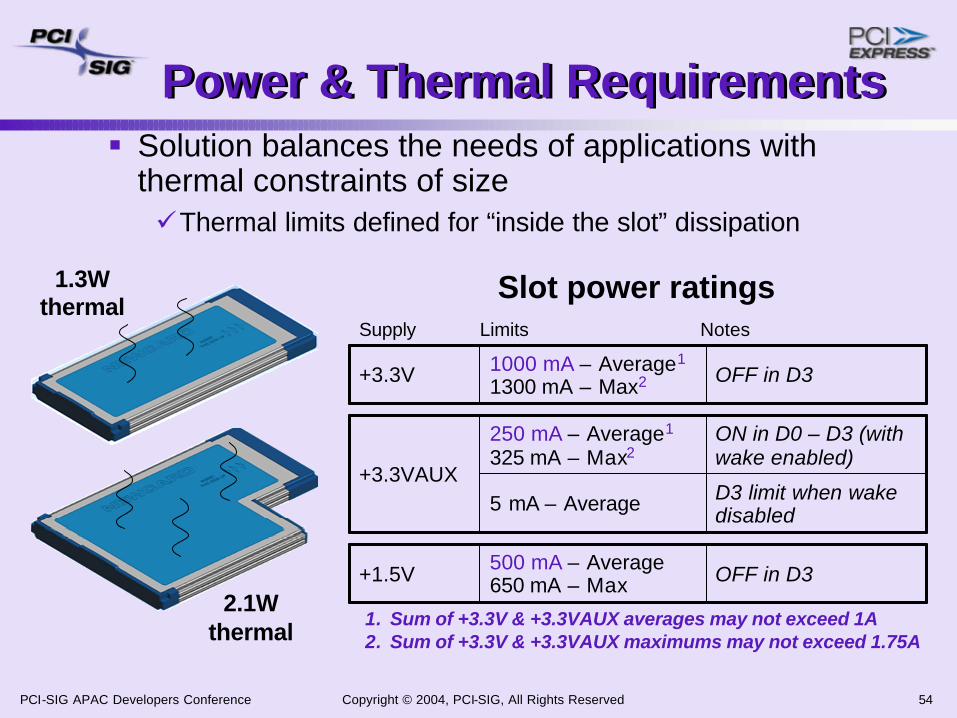
Power & Thermal RequirementsPower & Thermal Requirements§ Solution balances the needs of applications with
thermal constraints of sizeüThermal limits defined for “inside the slot” dissipation
1.3Wthermal
D3 limit when wake disabled5 mA – Average
ON in D0 – D3 (with wake enabled)
250 mA – Average1
325 mA – Max2
+3.3VAUX
OFF in D3500 mA – Average650 mA – Max+1.5V
OFF in D31000 mA – Average1
1300 mA – Max2+3.3V
Supply Limits Notes
1. Sum of +3.3V & +3.3VAUX averages may not exceed 1A2. Sum of +3.3V & +3.3VAUX maximums may not exceed 1.75A
2.1Wthermal
Slot power ratings

Copyright © 2004, PCI-SIG, All Rights Reserved 55PCI-SIG APAC Developers Conference
System ConfigurationsSystem Configurations§ Location of slots vary for desktop & mobileüBased on application and accessibility needs
§ Platform-independent recommendationsüSupport multiple slots in a platform
– Single slot solutions seriouslylimit usage flexibility
üProvide at least one slot for ExpressCard/54 modules
– Supports CF adapters,Smart Card adapters, larger rotating-media drives
Two universal Slots
Universal Slot
Two single slots
PC Card on top universal ExpressCard
slot on bottom

Copyright © 2004, PCI-SIG, All Rights Reserved 56PCI-SIG APAC Developers Conference
System Desktop ConceptsSystem Desktop Concepts
Power from system PSU
PCI Express CableUSB Cable
Cableddaughter cards
OEM-specificriser card

Copyright © 2004, PCI-SIG, All Rights Reserved 57PCI-SIG APAC Developers Conference
SystemSystemResetReset
3.3V3.3V
3.3V3.3VAUXAUX
1.5V1.5V
GROUND
USBD-USBD+
CPUSB#RESERVEDRESERVED
SMB_CLKSMB_DATA
+1.5V
+1.5VWAKE#
+3.3VAUX
PERST#+3.3V+3.3V
CLKREQ#CPPE#
REFCLK-
REFCLK+GROUND
PERn0
PERp0GROUND
PETn0
PETp0GROUND
121110
98
1514
7
25
242322
2120
1
23
456
13
161718
19
26
Power to the Slot
§ No 5V USB bus powerüReplaced with regulated 3.3V (&
1.5V)ü 3.3V auxiliary current on
a separate pin üReplace regulator with
rail switching in designs
Simpler solution – no controller / software connectionSimpler solution Simpler solution –– no controller / software connectionno controller / software connection
§ Slot is cold when un-occupiedüModule presence pins dictate when
power is needed– No software needed
ü System in sleep state (S3/S4) – Special case – after insertion, power to
module held off until after system returns to S0
Copyright © 2004, PCI-SIG, All Rights Reserved 58PCI-SIG APAC Developers Conference
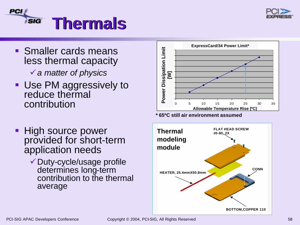
ThermalsThermals
§ Smaller cards means less thermal capacityüa matter of physics
§ Use PM aggressively to reduce thermal contribution
§ High source power provided for short-term application needsüDuty-cycle/usage profile
determines long-term contribution to the thermal average
BOTTOM,COPPER 110
FLAT HEAD SCREW#0-80, 2X
TOP, COPPER 110
CONNHEATER, 25.4mmX50.8mm
BOTTOM,COPPER 110
FLAT HEAD SCREW#0-80, 2X
TOP, COPPER 110
CONNHEATER, 25.4mmX50.8mm
* 65ºC still air environment assumed
Adjacent ExpressCard|34 Power Limit
0
0.2
0.4
0.6
0.8
1
1.2
1.4
1.6
1.8
0 5 10 15 20 25 30 35Power Limit [W]
Allo
wab
le T
emp R
ise
[C]
Allowable Temperature Rise [ºC]
Po
wer
Dis
sip
atio
n L
imit
[W
]
ExpressCard/34 Power Limit*
Thermalmodelingmodule

Copyright © 2004, PCI-SIG, All Rights Reserved 59PCI-SIG APAC Developers Conference
Power ManagementPower Management§ Support for PM in modules is mandatoryüActive State PM (PCI Express – L0s & L1)üD3 support (PCI Express & USB 2.0)
§ Wakeup mechanismsüPCI Express
– WAKE# – sideband to wake system power– PME in-band messaging
üUSB– USB in-band wake signaling

Copyright © 2004, PCI-SIG, All Rights Reserved 60PCI-SIG APAC Developers Conference
Modules using both PCI Expressand USB in a single instanceModules using both PCI Expressand USB in a single instance
§ Current bus driver stacks: no knowledge of physical dependencyüWhen a request is made to remove or stop a function: one
function will be knowingly removed, the other function will suffer surprise removal
§ Use ACPI – legacy solutionü_EJD (Eject Dependencies) – cross declarations in port
descriptions
§ Updated driver stacks – future solutionüRequire serial numbers be implemented in the PCI Express
Extended Configuration SpaceüReflect the PCI Express serial number in USB device
configuration space under a new string descriptor

Copyright © 2004, PCI-SIG, All Rights Reserved 61PCI-SIG APAC Developers Conference
Ease-of-Use ConsiderationsEase-of-Use Considerations§ Surprise insertion and removalüHW/SW tolerant of user actions
§ Module extraction from the slotüSpec targeted at manual removal over need for
ejector systems
§ Module installation is independent of which interface used by the application§ Proper marking and labeling techniques aids in
module insertion

Copyright © 2004, PCI-SIG, All Rights Reserved 62PCI-SIG APAC Developers Conference
ExpressCard ComplianceExpressCard Compliance§ Will be tied to ExpressCard
logo usage for registered products
§ Proposed compliance programüCombination of checklist & interop testing
– Requires use of silicon that meets PCI-SIG and USB-IF silicon compliance programs
üCo-sponsored SIG events to ease participation costs

Copyright © 2004, PCI-SIG, All Rights Reserved 63PCI-SIG APAC Developers Conference
Application OpportunitiesApplication Opportunities§ Transition existing applications from CardBus to
ExpressCard technologyüLeverage the broad range of existing USB silicon
§ Introduce new applications üEnabled by PCI Express and USBüNew desktop platform and consumer opportunities
1.8” HD app
Designed for adapters, rotating media, higher
power applicationsDesigned as long term form factor, fit for smaller next generation systems

Copyright © 2004, PCI-SIG, All Rights Reserved 64PCI-SIG APAC Developers Conference
Target ApplicationsTarget Applications
Sideband system management100 Kbps(half-duplex)SMBus2
Wired & Wireless WANWireless PANFlash Memory
SFF Flash Card AdaptersSecurity
Legacy I/O (PS2, serial, parallel)Optical Disk Drives
GPS Receiver
1 Mbpsto
480 Mbps(half-duplex)
USB 2.0
Wired & Wireless LANBroadband modems
Audio/Video SteamingTV Tuners/Decoders
I/O Adapters (e.g. 1394a/b)Magnetic Disk Drives
2.0 Gbps (full-duplex)PCI Express
Target ApplicationsPerformance1Interface
1 nominal data throughput 2 optional host feature
Copyright © 2004, PCI-SIG, All Rights Reserved 65PCI-SIG APAC Developers Conference
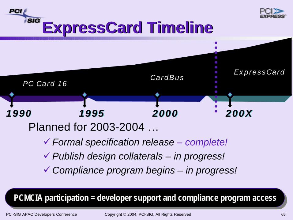
200X200X200020001995199519901990
CardBusExpressCard
PC Card 16
ExpressCard TimelineExpressCard Timeline
Planned for 2003-2004 … üFormal specification release – complete!üPublish design collaterals – in progress!üCompliance program begins – in progress!
PCMCIA participation = developer support and compliance program accessPCMCIA participation = developer support and compliance program PCMCIA participation = developer support and compliance program accessaccess

Copyright © 2004, PCI-SIG, All Rights Reserved 66PCI-SIG APAC Developers Conference
ExpressCard SummaryExpressCard Summary§ The ExpressCard Standard enables modular
card solutions for PCI Express and USB
§ ExpressCard technology is targeted for a wide range of platforms including mobile and desktop PCs
§ ExpressCard solutions will provide the best end-user experience for PC upgrades
Copyright © 2004, PCI-SIG, All Rights Reserved 67PCI-SIG APAC Developers Conference
ExpressCard Next StepsExpressCard Next Steps§ Module and system developers: join and
participate in the PCMCIA
www.expresscard.org
§ Silicon developers: design ingredients for ExpressCard applications emphasizing low power and power management features
§ Get ExpressCard technology included on your 2004 product roadmaps

Copyright © 2004, PCI-SIG, All Rights Reserved 68PCI-SIG APAC Developers Conference
SummarySummary§ PCI Express functions will be available in a wide
variety of form factors serving multiple market segments§ Each form factor addresses the specific
physical, power, thermal and performance needs of the markets they are intended to serve§ Each form factor has a solid transition strategy
for end-users/customers

Copyright © 2004, PCI-SIG, All Rights Reserved 69PCI-SIG APAC Developers Conference
Call to ActionCall to Action§ Prepare your product roadmaps to
intercept the first launch of systems, cards, and modules
§ Utilize the PCI-SIG (and other industry groups, as appropriate) for specifications and support

Copyright © 2004, PCI-SIG, All Rights Reserved 70PCI-SIG APAC Developers Conference
Thank you for attending the 2004 PCI-SIG Asia-PacificDevelopers Conference.
For more information please go to www.pcisig.com

Copyright © 2004, PCI-SIG, All Rights Reserved 71PCI-SIG APAC Developers Conference