chopper amplifiers...' 2004 national semiconductor corporation chopper amplifiers Ła chopper...
TRANSCRIPT

Chopper Amplifiers
Achieving Precision

© 2004 National Semiconductor Corporation
2
Paul RakoStrategic Application EngineerAmplifiers Group
Chopper Amplifiers

© 2004 National Semiconductor Corporation
Chopper Amplifiers
�A chopper amplifier is a type of amplifier that exhibits precise outputs and low noise.
�Also called Auto-Zero, Auto-Null, Ping-Pong, Stabilized and Commutated Amplifier.
�A chopper amplifier is often a compound amplifier.

© 2004 National Semiconductor Corporation
What is a Chopper good For?
�What is a precision amplifier?�Why does offset matter?�Terms: Bias, common mode, gain, modulation, servo, AC coupling,

© 2004 National Semiconductor Corporation
What’s the big deal with offset voltage?
�What is a precision amplifier?�Why does offset matter?�Terms: Bias, common mode, gain,chopper amplifier, servo, inverting

© 2004 National Semiconductor Corporation
Precision Defined:
�A precision amplifier is an amplifier that outputs and accurate representation of the input signal. This output will be accurate from part to part, over time and over temperature, barometric pressure, sunspots and any other external factors.

© 2004 National Semiconductor Corporation
Precision Defined:

© 2004 National Semiconductor Corporation
Offset Voltage
�Offset voltage is the voltage difference on the minus input pin of an amplifier that causes the output to be the same as the plus input pin (with Vcm=0).
Vos
A=1,000,000+
-

© 2004 National Semiconductor Corporation
Offset Voltage measurement
�Here is a way to measure it in closed-loop configuration.
5 volts
2.5 voltsVos
A=1+
-

© 2004 National Semiconductor Corporation
How does offset hurt precision?
� If the gain was 1000 the error would be a full volt.
�A one millivolt offset heremakes a tenth of a volt error here.
A= -100
© 2004 National Semiconductor Corporation
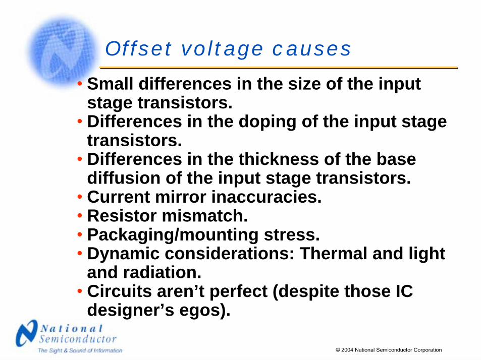
Offset voltage causes
� Small differences in the size of the input stage transistors.
� Differences in the doping of the input stage transistors.
� Differences in the thickness of the base diffusion of the input stage transistors.
� Current mirror inaccuracies.� Resistor mismatch.� Packaging/mounting stress.� Dynamic considerations: Thermal and light
and radiation.� Circuits aren’t perfect (despite those IC
designer’s egos).

© 2004 National Semiconductor Corporation
Amplifier Input Stage

© 2004 National Semiconductor Corporation
Noise
Some
CircuitVout
Time Domain
Freq Domain

© 2004 National Semiconductor Corporation
Amplifier Noise
Some
AmplifierVout
Time Domain
Freq Domain
1/f corner

© 2004 National Semiconductor Corporation
Amplifier Input Noise
Some Amplifier
Vn
Freq Domain
1/f corner

© 2004 National Semiconductor Corporation
Amplifier Input Noise Plot
(i.e.� a spectrum analyzer)
1/f corner
Freq Domain
nV/√Hz
area

© 2004 National Semiconductor Corporation
Chopper Amplifier Noise
(i.e.� a spectrum analyzer)
So it must improve this too.
Frequency Domain
You know it works good at DC.
Chopping freq (the price you pay).

© 2004 National Semiconductor Corporation
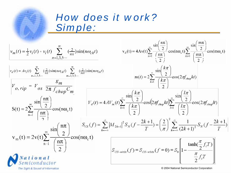
How does it work?Simple:
© 2004 National Semiconductor Corporation
How does it work?Simple:

© 2004 National Semiconductor Corporation
How to reduce offset
�Tweak and adjust the input stage�Tweak and adjust later stages�Tweak and adjust the output (yuk)
Or :
�Measure it and “servo” it out.�Use AC amplification.

© 2004 National Semiconductor Corporation
Chopper benefits:
�Reduces the offset from part to part.�Reduces the offset over time�Reduces the offset over temperature.
�Reduces offset over common mode voltage.

© 2004 National Semiconductor Corporation
Chopper architectures
� Auto-nulling (auto-zero)� Synchronous switching (True chopper)� Single vs. compound

© 2004 National Semiconductor Corporation
The Quandary:
�How to measure the offset of an amplifier in order to “servo” it out when whatever you measure it with will also have a unique (and different) offset?

© 2004 National Semiconductor Corporation
Auto Nulling amp
A= -100

© 2004 National Semiconductor Corporation
Auto Nulling amp (mo’ betta)
A= -100

© 2004 National Semiconductor Corporation
Auto Nulling Defined
�A Nulling (or auto zero) amp works as an amp for a little while, then corrects its offset voltage, then it goes back to working as an amplifier again. How often? 100 Hz – 1000 kHz is commonly seen.

© 2004 National Semiconductor Corporation
Simple Chopper amp
A= -100
10mV

© 2004 National Semiconductor Corporation
Simple Chopper amp
A= -100
10mV
10mV

© 2004 National Semiconductor Corporation
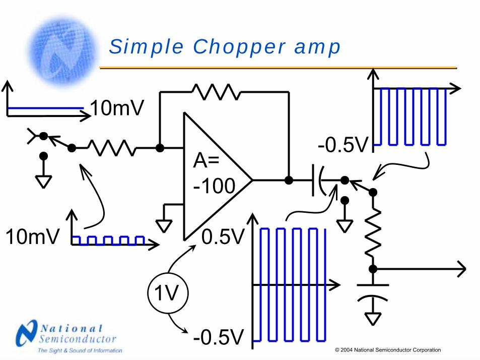
Simple Chopper amp
A= -100
10mV
10mV
1V
0.5V
-0.5V
© 2004 National Semiconductor Corporation
Simple Chopper amp
A= -100
10mV
10mV
1V
0.5V
-0.5V
-0.5V

© 2004 National Semiconductor Corporation
Simple Chopper amp
A= -100
10mV
10mV
1V
0.5V
-0.5V
-0.5V
-0.23V

© 2004 National Semiconductor Corporation
Simple Chopper amp (mo’ betta)
A= -100
10mV
10mV 0.5V
-0.5V
-0.5V
1V

© 2004 National Semiconductor Corporation
“Classic” Chopper amp
A= -100
10mV
10mV 0.5V
-0.5V
-0.5V
1V
© 2004 National Semiconductor Corporation
Chopping Defined
�A Chopper (or commutating) amp modulates the input to create an AC signal that can be amplified with and AC amp, then it demodulates the AC back to DC. How often? 100 Hz – 25,000 KHz is commonly seen.

© 2004 National Semiconductor Corporation
Compound Amp (Bias adjust)
A= -100
+-
+-
A= -200

© 2004 National Semiconductor Corporation
Compound Amp (Offset servo)
A= 100+-
+-
A= 100
Except for the stuff I stole from Eric Nolan at Analog Devices (Demystifying Auto-Zero Amplifiers� Part 1)

© 2004 National Semiconductor Corporation
Compound Amp (Dual input)
+-
+-
+-
Fast amplifier
Fast amplifier
Low offset amplifier
© 2004 National Semiconductor Corporation
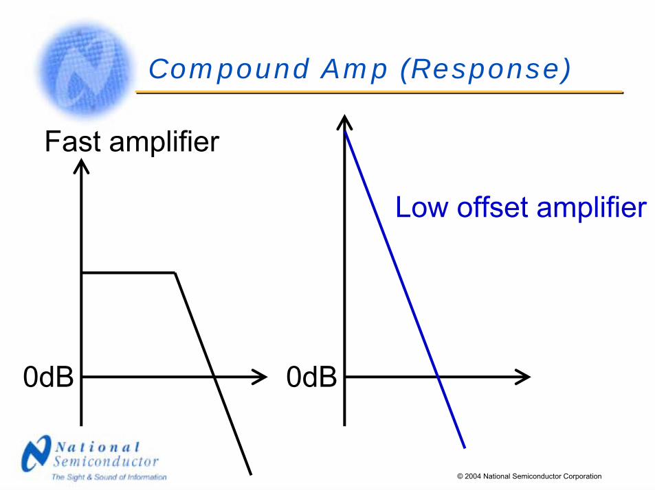
Compound Amp (Response)
Fast amplifier
Low offset amplifier
0dB 0dB

© 2004 National Semiconductor Corporation
Compound Amp (Response)
Fast amplifier
Low offset amplifier
0dB

© 2004 National Semiconductor Corporation
Synchronous Demodulation
+-
This pair of switches reverses the offset voltage of this amplifier. Offset becomes a square wave
centered around zero (for a shorted input).

© 2004 National Semiconductor Corporation
Synchronous Demodulation
+-
Vos-Vos

© 2004 National Semiconductor Corporation
Synchronous Demodulation
Note that any signal at the main amplifier input would also get
filtered out.
+-

© 2004 National Semiconductor Corporation
Synchronous Demodulation
+-
So add these switches to reverse the input polarity synchronously
with the output switches.

© 2004 National Semiconductor Corporation
Synchronous Demodulation
+-
Vos-Vos(Vin)x(-A)
Vin

© 2004 National Semiconductor Corporation
Synchronous Demodulation
+-
To remove the AC offset add a Low-Pass Filter

© 2004 National Semiconductor Corporation
Synchronous Demodulation
+-
(Vin)x(-A)

© 2004 National Semiconductor Corporation
Compound Amp (Fast section)
+-
+-
+
-

© 2004 National Semiconductor Corporation
Compound Amp (Kill DC gain)
+-
+-
+-
+
-
© 2004 National Semiconductor Corporation
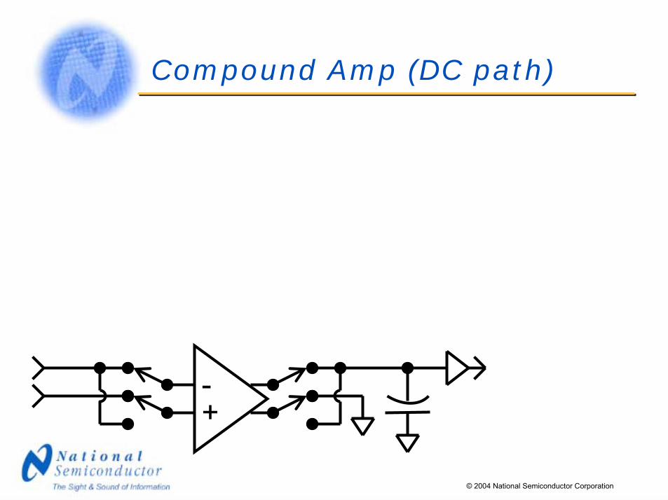
Compound Amp (DC path)
+-

© 2004 National Semiconductor Corporation
Compound Amp (Complete)
+-
+-
Except for the stuff I stole from Martin Giles (Precision Op Amps)
+-
+-
© 2001 National Semiconductor Corporation
+
-

© 2004 National Semiconductor Corporation
Compound Amp (Buy one!)
LMV2011

© 2004 National Semiconductor Corporation
How low is the offset?
�LMV2011 ~ 0.8 microvolts�AD8551 ~ 1 microvolts�TLC2652AI ~ 0.5 microvolts�OPA735 ~ 1 microvolt�LTC2050 ~ +/- 0.5 microvolts�MAX4238 ~ 0.1 microvolts

© 2004 National Semiconductor Corporation
What runs the switches?
�A fixed clock�A variable clock�A spread-spectrum clock

© 2004 National Semiconductor Corporation
What is the frequency?
�25 kHz for the LMV2011�20 kHz for the MAX4238�7.5 kHz for the LTC2050�18 kHz for the OPA734�4 kHz for the AD8551

© 2004 National Semiconductor Corporation
Disadvantages
�Clock noise.�Slow Speed.�Cost (until we started making them).�Variable Input AC impedance.

© 2004 National Semiconductor Corporation
Thank You!
� If you have questions for our presenter, please send them to our customer response center at [email protected].
� The online technical journal National Edge is available at http://www.national.com/nationaledge/.
� Sign up for National’s biweekly newsletter, News@National by updating your online profile at http://www.national.com/profile/user_info.cgi.