chips communications system - mine safety appliances
TRANSCRIPT

CHIPSCommunicationsSystem
Operating Manual
"!THIS MANUAL MUST BE CAREFULLY READ BY ALLINDIVIDUALS WHO HAVE OR WILL HAVE THERESPONSIBILITY FOR USING OR SERVICING THEPRODUCT. Like any piece of complex equipment, thisproduct will perform as designed only if it is used andserviced in accordance with the manufacturer’sinstructions. OTHERWISE, IT COULD FAIL TOPERFORM AS DESIGNED AND PERSONS WHO RELYON THIS PRODUCT FOR THEIR SAFETY COULDSUSTAIN SEVERE PERSONAL INJURY OR DEATH.
The warranties made by Mine Safety AppliancesCompany with respect to the product are voided if thesystem is not used and serviced in accordance withthe instructions in this manual. Please protect yourselfand others by following them. We encourage ourcustomers to write or call regarding this equipmentprior to use or for any additional information relative touse or repairs.
In North America, to contact 1-800-MSA-2222
© MINE SAFETY APPLIANCES COMPANY 2009 - All RightsReserved
This manual is available on the internet at www.msanet.com
Manufactured by
MSAP.O. Box 427, Pittsburgh, Pennsylvania 15230
(L) Rev 1 10100799
" WARNING

Table of Contents
Chapter 1, CHIPS Communications System Overview . .1-1
Chapter 2,High-Noise Circum-aural Headset . . . . . . . . . .2-1
Level Dependent/ Return Guarantee (FIGURE 2-1) . . . . . . . .2-1Figure 2-1. . . . . . . . . . . . . . . . . . . . . . . . . . . . . . . . . . . . . . . . .2-2
Battery Installation and Replacement (FIGURE 2-2) . . . . . . . .2-3
Battery Installation (FIGURE 2-2) . . . . . . . . . . . . . . . . . . . . . . .2-4Figure 2-2. . . . . . . . . . . . . . . . . . . . . . . . . . . . . . . . . . . . . . . . .2-4
Function Keys (See FIGURE 2-3) . . . . . . . . . . . . . . . . . . . . . .2-5
ON and OFF, (O) . . . . . . . . . . . . . . . . . . . . . . . . . . . . . . . . . . .2-5
Volume Adjustment, (+) (-) . . . . . . . . . . . . . . . . . . . . . . . . . . . .2-5
Battery-Saving Mode . . . . . . . . . . . . . . . . . . . . . . . . . . . . . . . .2-5Figure 2-3. . . . . . . . . . . . . . . . . . . . . . . . . . . . . . . . . . . . . . . . .2-5
Amplification . . . . . . . . . . . . . . . . . . . . . . . . . . . . . . . . . . . . . . .2-6
Battery-Saving Function – Warning before Switching OFF . . .2-6
Battery Warning . . . . . . . . . . . . . . . . . . . . . . . . . . . . . . . . . . . .2-6
Fitting Instructions . . . . . . . . . . . . . . . . . . . . . . . . . . . . . . . . . .2-7
" WARNING . . . . . . . . . . . . . . . . . . . . . . . . . . . . . . . . . . . . .2-7Figure 2-4. . . . . . . . . . . . . . . . . . . . . . . . . . . . . . . . . . . . . . . . . .2-7
Noise Cancelling Boom Microphone (mic) . . . . . . . . . . . . . . . .2-8Figure 2-5. . . . . . . . . . . . . . . . . . . . . . . . . . . . . . . . . . . . . . . . .2-8
Cleaning . . . . . . . . . . . . . . . . . . . . . . . . . . . . . . . . . . . . . . . . . .2-9
Maintenance . . . . . . . . . . . . . . . . . . . . . . . . . . . . . . . . . . . . . . .2-9
Storage . . . . . . . . . . . . . . . . . . . . . . . . . . . . . . . . . . . . . . . . . .2-10
" CAUTION . . . . . . . . . . . . . . . . . . . . . . . . . . . . . . . . . . . . .2-10
High Noise Circum-Aural Headset Troubleshooting Guidelines . . . . . . . . . . . . . . . . . . . . . . . . . . .2-11
" WARNING . . . . . . . . . . . . . . . . . . . . . . . . . . . . . . . . . . . . .2-11
" WARNING . . . . . . . . . . . . . . . . . . . . . . . . . . . . . . . . . . . . .2-11
i

Tested to ANSI Specifications, ANSI S3.19-1974 . . . . . . . . . .2-13
Attenuation Data – Headband Foam Seal . . . . . . . . . . . . . . .2-13
Attenuation Data – Headband Gel Seal . . . . . . . . . . . . . . . . .2-13
Attenuation Data – Neckband Foam Seal . . . . . . . . . . . . . . .2-14
Attenuation Data – Neckband Gel Seal . . . . . . . . . . . . . . . . .2-14
" CAUTION . . . . . . . . . . . . . . . . . . . . . . . . . . . . . . . . . . . . .2-14
" WARNING . . . . . . . . . . . . . . . . . . . . . . . . . . . . . . . . . . . .2-15
Throat Microphone (optional accessory) . . . . . . . . . . . . . . . .2-16
Donning the Throat Microphone . . . . . . . . . . . . . . . . . . . . . . .2-16Figure 2-6. . . . . . . . . . . . . . . . . . . . . . . . . . . . . . . . . . . . . . . . .2-16
Adjusting the Throat Microphone Position . . . . . . . . . . . . . . .2-17Figure 2-7. . . . . . . . . . . . . . . . . . . . . . . . . . . . . . . . . . . . . . . . .2-17Figure 2-8. . . . . . . . . . . . . . . . . . . . . . . . . . . . . . . . . . . . . . . . .2-17
Chapter 3, High-Noise In Ear Communication System . . .3-1
Figure 3-1. . . . . . . . . . . . . . . . . . . . . . . . . . . . . . . . . . . . . . . . . .3-1
Operation . . . . . . . . . . . . . . . . . . . . . . . . . . . . . . . . . . . . . . . . .3-2Figure 3-2. . . . . . . . . . . . . . . . . . . . . . . . . . . . . . . . . . . . . . . . . .3-2
Cleaning . . . . . . . . . . . . . . . . . . . . . . . . . . . . . . . . . . . . . . . . . .3-4
Tested according to ANSI Specifications, ANSI S3.19-1974 . .3-6
" WARNING . . . . . . . . . . . . . . . . . . . . . . . . . . . . . . . . . . . . .3-6
Attenuation Data – MSA In-Ear Communication System . . . . .3-7
" CAUTION . . . . . . . . . . . . . . . . . . . . . . . . . . . . . . . . . . . . . .3-7
" WARNING . . . . . . . . . . . . . . . . . . . . . . . . . . . . . . . . . . . . .3-9
ii

Chapter 4, Low-Noise/High-Noise Communication Headset . . . . . . . . . . . . . . . . . .4-1
Figure 4-1. . . . . . . . . . . . . . . . . . . . . . . . . . . . . . . . . . . . . . . . . .4-1
Positioning the Conduction Transducers . . . . . . . . . . . . . . . . .4-3Figure 4-2. . . . . . . . . . . . . . . . . . . . . . . . . . . . . . . . . . . . . . . . . .4-3Figure 4-3 . . . . . . . . . . . . . . . . . . . . . . . . . . . . . . . . . . . . . . . . .4-3
Adjusting the Microphone Position . . . . . . . . . . . . . . . . . . . . . .4-4
Cleaning . . . . . . . . . . . . . . . . . . . . . . . . . . . . . . . . . . . . . . . . . .4-4
Storage . . . . . . . . . . . . . . . . . . . . . . . . . . . . . . . . . . . . . . . . . . .4-4
Chapter 5, CHIPS PTT Control Module . . . . . . . . . . . . . . . .5-1
Figure 5-1. . . . . . . . . . . . . . . . . . . . . . . . . . . . . . . . . . . . . . . . . .5-2
Port and Button Descriptions . . . . . . . . . . . . . . . . . . . . . . . . . .5-3
1. Two-Port Headset Junction Block . . . . . . . . . . . . . . . . . . . . .5-3
2. Three-Port Radio/Intercom Junction Block . . . . . . . . . . . . . .5-4
3. Radio 1 PTT Button . . . . . . . . . . . . . . . . . . . . . . . . . . . . . . .5-5
4. Radio 2 PTT Button . . . . . . . . . . . . . . . . . . . . . . . . . . . . . . .5-5
5. VIC-3 Momentary PTT Button . . . . . . . . . . . . . . . . . . . . . . .5-5
6. VIC-3 PTT Latch Button . . . . . . . . . . . . . . . . . . . . . . . . . . . .5-5
7. Intercom Interface . . . . . . . . . . . . . . . . . . . . . . . . . . . . . . . . .5-6
8. Volume Up Button . . . . . . . . . . . . . . . . . . . . . . . . . . . . . . . . .5-6
9. Volume Down Button . . . . . . . . . . . . . . . . . . . . . . . . . . . . . .5-7
10. MODE Button . . . . . . . . . . . . . . . . . . . . . . . . . . . . . . . . . . .5-8
11. Pressing the VOLUME UP, VOLUME DOWN and MODE buttons at the Same Time . . . . . . . . . . . . . . . . . . . . . .5-9
Mode 1: In-Ear Headset Communication System . . . . . . . . .5-10
Mode 2:In-Ear and Circum-Aural Headset Communication System . . . . . . . . . . . . . . . . . . . . . . . . . . . . .5-10
Mode 3: Circum-Aural Headset Communication System Only5-11
Mode 4: In-Ear and Low Noise Headset . . . . . . . . . . . . . . . .5-11
Mode 5: Low Noise Headset . . . . . . . . . . . . . . . . . . . . . . . . . .5-12
Mode 6 - Failsafe Mode . . . . . . . . . . . . . . . . . . . . . . . . . . . . .5-12
iii

Mode 7: Stand-alone Circum-Aural High-noise Headset . . . .5-13
Additional Functions and Features . . . . . . . . . . . . . . . . . . . . .5-13
Automatic Single Comm/Dual Comm Speaker configuration .5-13
High Noise Headset . . . . . . . . . . . . . . . . . . . . . . . . . . . . . . . .5-13
In-Ear Headset . . . . . . . . . . . . . . . . . . . . . . . . . . . . . . . . . . . .5-14
Battery Run Time . . . . . . . . . . . . . . . . . . . . . . . . . . . . . . . . . .5-15
Auto Shutdown . . . . . . . . . . . . . . . . . . . . . . . . . . . . . . . . . . . .5-15
Voice Annunciation . . . . . . . . . . . . . . . . . . . . . . . . . . . . . . . . .5-16
Battery Replacement . . . . . . . . . . . . . . . . . . . . . . . . . . . . . . .5-16
Maintenance . . . . . . . . . . . . . . . . . . . . . . . . . . . . . . . . . . . . . .5-16
CHIPS PTT Troubleshooting Guidelines . . . . . . . . . . . . . . . .5-17
Fully Integrated System . . . . . . . . . . . . . . . . . . . . . . . . . . . . .5-18
" CAUTION . . . . . . . . . . . . . . . . . . . . . . . . . . . . . . . . . . . . .5-18Figure 5-2. . . . . . . . . . . . . . . . . . . . . . . . . . . . . . . . . . . . . . . . .5-19
Key Points to Proper Mounting . . . . . . . . . . . . . . . . . . . . . . . .5-20Figure 5-3. . . . . . . . . . . . . . . . . . . . . . . . . . . . . . . . . . . . . . . .5-20
Mounting Checklist . . . . . . . . . . . . . . . . . . . . . . . . . . . . . . . . .5-21
Chapter 6,CHIPS Communication System Specifications . . . . . . . . . . . . . . . . . . . . . . . . . . .6-1
Specifications . . . . . . . . . . . . . . . . . . . . . . . . . . . . . . . . . . . . . .6-1
General Communication System Warranty . . . . . . . . . . . . . . . .6-2
Unit Warranty Procedures . . . . . . . . . . . . . . . . . . . . . . . . . . . . .6-4
Maintenance Request Minimum Information . . . . . . . . . . . . . .6-4
Parts LIst . . . . . . . . . . . . . . . . . . . . . . . . . . . . . . . . . . . . . . . . . .6-5
iv
Chapter 1, CHIPS Communications SystemOverview
The CHIPS Communications System is anunobtrusive communication and hearing protection system designed for rugged use andmaximum flexibility.
The complete system consists of:
• three user-selectable headsets including:
• a high-noise, circum-aural headset
• a high-noise, in-ear system
• a low-noise/high-noise, bone conduction headset
• an intelligent PPT/control module capable offunctioning in a tri-com configuration
• rugged Military cables and connectors thatinterface with Military radios and vehicle intercom systems
• canvas carrying bag.
1-1

Chapter 2,High-Noise Circum-aural Headset
The High noise headset:
• is for use in noisy environments
• consists of:
• a circum-aural muff-based headset withspeakers and spy microphone assembliesthat provide talk through capabilities
• a boom microphone for communication
• uses a neckband or headband head assemblythat allows use of an ACH Ballistic Helmet whileproviding situational awareness communicationsand hearing protection.
Level Dependent/ Return Guarantee(FIGURE 2-1)
The High noise headset is equipped with a soundpressure level-dependent function. It consists of twoexternally-mounted spy microphones that pick up theambient sound (A1).
2-1

Do not mix units with different areaclassifications. All units
Ambient sound is reproduced in stereo to maintain orimprove situational awareness in environments whereit is desirable that ambient sound be heard, e.g.,warning signals, conversation, traffic, etc. Internalelectronics limit the ambient sound pressure levelinside the headset to a safe level (82 dB).
Figure 2-1.
2-2

Battery Installation and Replacement (FIGURE 2-2)
The product is equipped with two standard 1.5 VAAA/LR03 batteries.
NOTE: Rechargeable batteries (such as NiMH 1.2 Vor NiCd 1.2 V) should not be used as theymay significantly reduce the operational life of the product.
The batteries are:
• completely enclosed to protect against moistureand dirt
• housed in the unique battery compartmentlocated in the right side cup.
2-3

Battery Installation (FIGURE 2-2)
1. Hold the cup upside down and unscrew thebattery cover (B1).
2. Insert the first battery with the (-) pole facinginward (B2).
3. Shake the cup lightly so that the battery falls intoplace(B3).
4. Insert the second battery with the (+) pole facinginward (B4).
5. Refit the battery cover (B5).
NOTE: Ensure that positive (+) and negative (-) battery poles are correctly aligned.
Do not mix units with different areaclassifications. All units
Figure 2-2.
2-4

Function Keys (See FIGURE 2-3)
ON and OFF, (O)
• Press (O) key to turn ON the electronic functions.
• To switch OFF the electronic functions, press andhold the same (O) key for two seconds.
Volume Adjustment, (+) (-)
• Briefly press the (+) key to turn up the volume.
• Briefly press the (-) key to turn down the volume.
• The volume starts at the level at which it wasswitched OFF.
• The volume can be adjusted in five steps.
• The output signal will not exceed known risklevels for hearing damage. Speaker sound islimited to maximum 82 dB.
Battery-Saving Mode
• This mode ensures maximum battery life.
• If no key is pressed during a four-hour period, theunit automatically switches OFF.
• To restart, push the (O) key, located at the middleof the keypad.
Figure 2-3.
2-5

Amplification
• At the two highest volume levels, theCommunication Headset amplifies the ambientsound by up to 12 dB.
Battery-Saving Function – Warning beforeSwitching OFF
• About two minutes before automatic switch-off, atone sounds as a warning that sound will beswitched OFF.
• Press any key to delay the switch-off by anadditional four hours.
Battery Warning
• A tone sounds when about 40 hours of batterylife remain.
• This battery warning sounds after 10 seconds at startup.
2-6
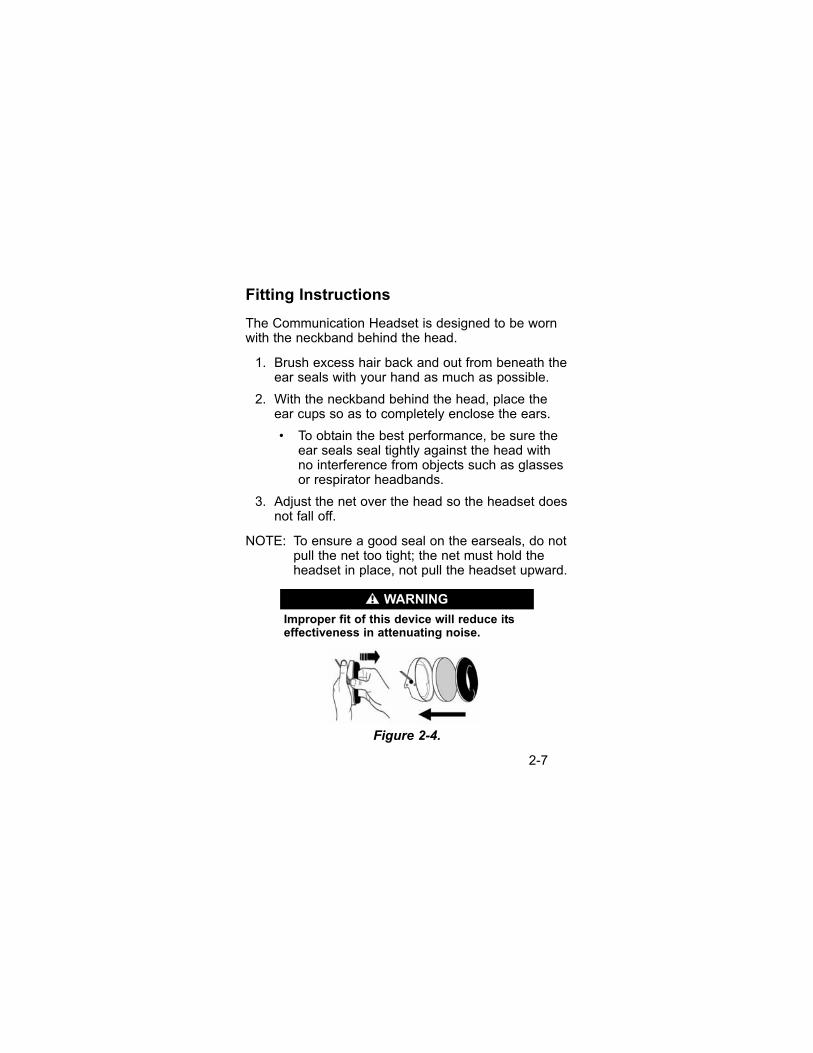
Fitting Instructions
The Communication Headset is designed to be wornwith the neckband behind the head.
1. Brush excess hair back and out from beneath theear seals with your hand as much as possible.
2. With the neckband behind the head, place theear cups so as to completely enclose the ears.
• To obtain the best performance, be sure theear seals seal tightly against the head withno interference from objects such as glassesor respirator headbands.
3. Adjust the net over the head so the headset doesnot fall off.
NOTE: To ensure a good seal on the earseals, do notpull the net too tight; the net must hold theheadset in place, not pull the headset upward.
Improper fit of this device will reduce itseffectiveness in attenuating noise.
Figure 2-4.
" WARNING
2-7
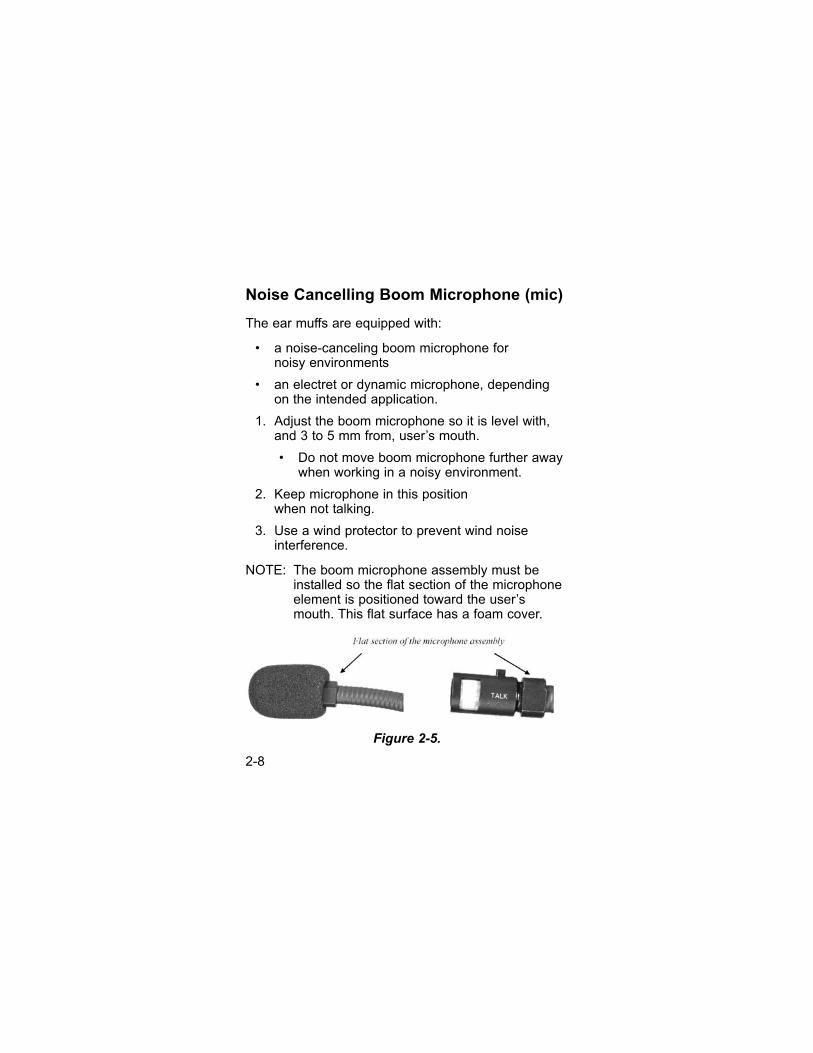
Noise Cancelling Boom Microphone (mic)
The ear muffs are equipped with:
• a noise-canceling boom microphone for noisy environments
• an electret or dynamic microphone, dependingon the intended application.
1. Adjust the boom microphone so it is level with,and 3 to 5 mm from, user’s mouth.
• Do not move boom microphone further awaywhen working in a noisy environment.
2. Keep microphone in this position when not talking.
3. Use a wind protector to prevent wind noiseinterference.
NOTE: The boom microphone assembly must beinstalled so the flat section of the microphoneelement is positioned toward the user’smouth. This flat surface has a foam cover.
Figure 2-5.
2-8
Cleaning
After use, wipe the product with a soft, wet cloth.
NOTE: Do not immerse in water.
Maintenance
1. Inspect the headset regularly to ensure good condition.
2. Clean the outside of the muff and the sealing ringwith soap and water, as needed.
3. Regularly inspect earmuffs and sealing rings forcracks and leakage due to possible deteriorationwith use and age.
• The sealing rings are replaceable. Worn ordamaged parts are easily replaced (FIGURE D).Use only hygiene kits designed for these MSAheadsets. To ensure that performance ismaintained, replace the hygiene kit twice a yearin normal use.
NOTE: This product may be adversely affectedby certain chemicals. Further informationcan be obtained from MSA.
4. Moisture can build up inside the hearing protectorif used for long periods. To avoid long-termaffects of moisture on the electronic components,regularly remove the acoustic absorbent to allowthe inside of the muffs to dry out, e.g., overnight(FIGURE 2-4).
2-9

When removing the cushion andabsorbent, be careful not to touch theelectronics or cables. Changing the position of cables can cause interferencein the system. Do not subject the headsetto rough handling, such as dropping itfrom heights; otherwise damage to the electronics can occur.
Do not immerse the headset in water; performance can be significantly reduced.
Storage
• Store the headset in a dry, cool place; do notleave it sitting in high heat or direct sunlight.
• When the headset is not in use, ensure that theneckband is not extended and that the sealingrings are not compressed.
• Keep the headset dry, clean and at normal roomtemperature.
• Do not allow the headset to lie in direct sunlight.
• If the product is to be stored for a long period,remove the batteries from the battery holder toprevent damage.
• Store the product in an unfolded position in orderto avoid damage to the ear seals.
" CAUTION
2-10

High Noise Circum-Aural Headset TroubleshootingGuidelines
PROBLEM SOLUTION
Electronics cease Replace the batteriesto function
Ensure batteries are correctly fitted in the hearing protector.
Ensure battery plates make good contact with the batteries.
Ensure battery plates are not coated
Moisture build-up on electronic Regularly remove thecomponents inside muffs acoustic absorbent so thedue to extended use muff interior can dry out,
e.g., overnight
NOTE: If these measures do not help, consult MSA
Inspect the system before each use. If anydeficiency is found, replace the damageditem before use.
The function may deteriorate with batteryusage. In normal use, the estimated life ofthe batteries is about 600 hours
The estimated A-weighed sound levelinside the muff, with consideration takento attenuation values, shall not exceed 82 dB(A).
Remember that hearing protectors generally can shut out ambient sound,
" WARNING
" WARNING
2-11

such as warning shouts, alarms and otherimportant signals. Therefore, be extra cautious of your surroundings when wearing hearing protectors.
The integrated microphones for reproduction of ambient sound increasesafety considerably in your daily activities.The output signal from the leveldependent function can exceed the actual external sound level.
The level dependent function may deteriorate in rain or moist conditions. Ifdeterioration occurs, immediately allowthe microphones in the hearing protectorto dry (with open muffs for 24 hours) untilthe function is fully restored.
The product and the batteries are to bedisposed of in conformance with nationalregulations.
Failure to follow the above can result inhearing loss.
2-12

Tested to ANSI Specifications, ANSI S3.19-1974
The level of noise entering a person’s ear, when hearingprotection is worn as directed, is closely approximated bythe difference between the A-weighted environmentallevel and the NRR.
Example: The environmental noise level at the ear is 92 dB(A). TheNRR is 23 decibels (dB). The level of noise entering theear is approximately equal to 69 dB(A).
Attenuation Data – Headband Foam Seal
Fre- 125 250 500 1000 2000 3150 4000 6300 8000 NRR quency (dB)(Hz)
Mean 15.7 19.8 24.7 25.8 27.9 33.7 38.5 41.6 43 20(dB)
Standard 3.9 3.2 2.8 2.6 2.1 2.2 3.3 3 3.7 20deviation (dB)
Attenuation Data – Headband Gel Seal
Fre- 125 250 500 1000 2000 3150 4000 6300 8000 NRR quency (dB)(Hz)
Mean 17.5 20.9 24.9 31.5 30.6 34.5 37.4 41.8 42.5 21(dB)
Standard 3.2 3.2 3 2.7 3.5 4.2 3.8 3.6 4.1 21deviation (dB)
2-13
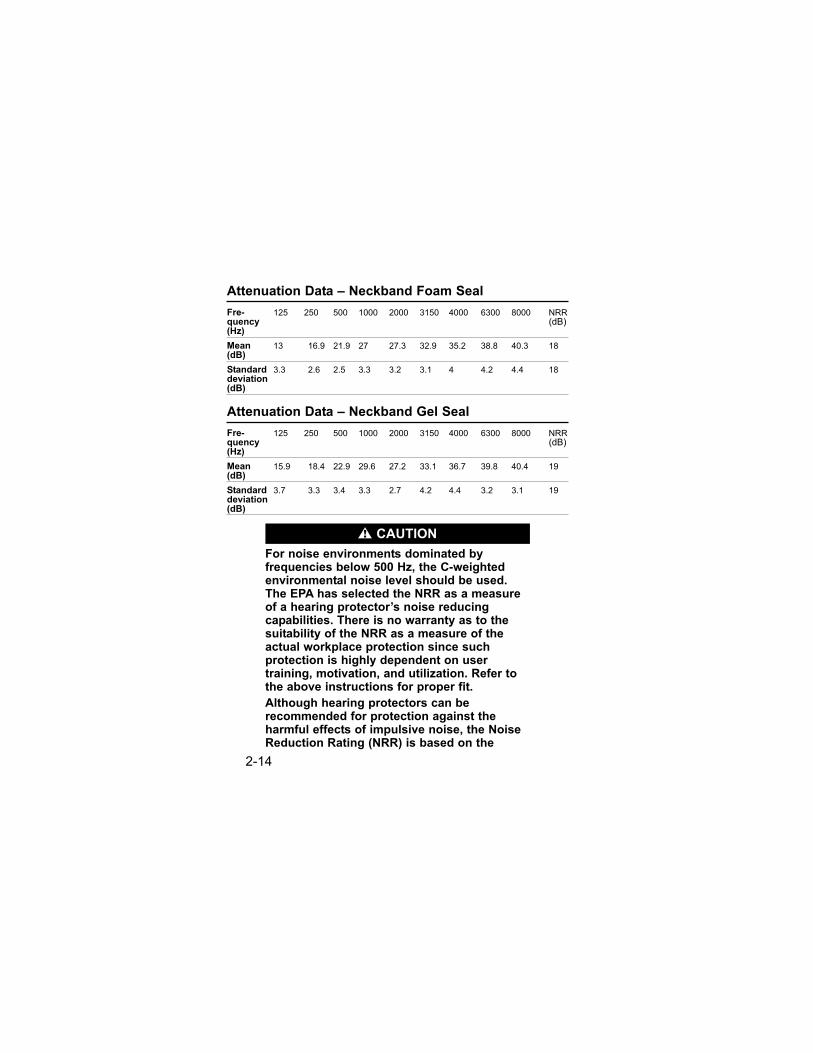
Attenuation Data – Neckband Foam Seal
Fre- 125 250 500 1000 2000 3150 4000 6300 8000 NRR quency (dB)(Hz)
Mean 13 16.9 21.9 27 27.3 32.9 35.2 38.8 40.3 18(dB)
Standard 3.3 2.6 2.5 3.3 3.2 3.1 4 4.2 4.4 18deviation (dB)
Attenuation Data – Neckband Gel Seal
Fre- 125 250 500 1000 2000 3150 4000 6300 8000 NRR quency (dB)(Hz)
Mean 15.9 18.4 22.9 29.6 27.2 33.1 36.7 39.8 40.4 19(dB)
Standard 3.7 3.3 3.4 3.3 2.7 4.2 4.4 3.2 3.1 19deviation (dB)
For noise environments dominated by frequencies below 500 Hz, the C-weightedenvironmental noise level should be used.The EPA has selected the NRR as a measureof a hearing protector’s noise reducingcapabilities. There is no warranty as to thesuitability of the NRR as a measure of theactual workplace protection since suchprotection is highly dependent on usertraining, motivation, and utilization. Refer tothe above instructions for proper fit.
Although hearing protectors can berecommended for protection against theharmful effects of impulsive noise, the NoiseReduction Rating (NRR) is based on the
" CAUTION
2-14

2-15
attenuation of continuous noise and may notbe an accurate indicator of the protectionattainable against impulsive noise such asgunfire.
The noise reduction capability of this hearing protector against impulsive noise may be estimated by referring to theattenuation performance of the hearingprotector at the frequency of the impulsivenoise exposure as provided in the attenuationdata on the package.
To estimate the noise reduction capability ofthis hearing protector against impulsive noise,refer to the Attenuation Data below or on theproduct package. If the frequency of theimpulsive noise is 2000 hertz (Hz), for example, the mean (average) reduction ofnoise attained by test subjects at thatfrequency was 32.1 decibels (dB). Using thestandard deviation of +2.8 dB, the estimatednoise reduction at 2000 Hz would range from29.3 dB to 34.9 dB. Refer to manufacturer ofequipment producing the impulsive noise todetermine the frequency.
An appropriate hearing conservation programmust be utilized that includes adequatemonitoring and audiometric testing to ensureeffective hearing protection. Improper use ofthe hearing protector or failure to conductadequate monitoring and testing can result inhearing loss or other serious personal injury.
" WARNING
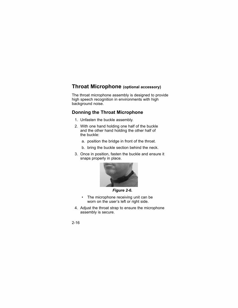
Throat Microphone (optional accessory)
The throat microphone assembly is designed to providehigh speech recognition in environments with highbackground noise.
Donning the Throat Microphone
1. Unfasten the buckle assembly.
2. With one hand holding one half of the buckle and the other hand holding the other half of the buckle:
a. position the bridge in front of the throat.
b. bring the buckle section behind the neck.
3. Once in position, fasten the buckle and ensure itsnaps properly in place.
• The microphone receiving unit can be worn on the user’s left or right side.
4. Adjust the throat strap to ensure the microphoneassembly is secure.
Figure 2-6.
2-16

• If the strap fit is too loose or too tight, adjustthe length of the strap.
Adjusting the Throat Microphone Position
It is important that the microphone is positioned in theproper location in order to obtain optimal audio andtransmission ability.
1. Locate the “hollow” of the throat area.
2. Carefully position the throat microphone housingat that particular position.
3. Adjust the strap length so the throat microphoneis pressed firmly against the skin, but is still comfortable.
Figure 2-8.
Figure 2-7.
2-17

Chapter 3, High-Noise In Ear Communication SystemThe High Noise In-Ear Communication System:
• consists of an in-ear headset positioned in theuser’s left and right ears.
• includes a speaker and spy microphones thatoffer the user talk-through and communicationcapabilities.
• uses an external bone conductive microphone tocapture vibrations in the user’s jawboneconverting them to crisp, clear sound.
Figure 3-1.
3-1

The In-Ear Communication Headset includes:
• Dual headset (one left and one right) with:
• Cable
• One common connector for both earpieces
• Spy microphone, protection mounted
• Speaker, protection mounted
• Wind protection, mounted
• Replaceable ear-spring, mounted
• Hearing protection plugs in different sizes
• Cable retainer
• Cable clips for connecting cable on the user
• Protective, lightweight and non reflectivestorage case.
Figure 3-2.
3-2

Operation
1. Inspect the Earpiece to ensure the correctearpiece version is inserted in the respectiveright or left ear canal.
2. Roll the foam insert back and forth between yourfingers to compress it so that it can be easilyinserted into the ear canal. The foam expandsafter a few minutes, creating a good seal.
3. Hold the earpiece in your right hand with the firstthree fingers. (For the left ear, use the left hand.)
• The soft spring points forward, with the tiptowards user’s ear.
• The cable points downward.
Place an index finger on the flat part between thespring and cable.
4. Insert the earpiece in user’s right ear and twist itcounter-clockwise approximately 90° while lightlypressing the index finger on the flat part. (For leftear, insert earpiece clockwise 90°.)
3-3

• Once inserted, the balloon points downward.
5. Use an index finger to apply pressure on the softspring, until it bends; insert spring in the upperbend of your ear.
• The soft spring ensures that the earpiecestays in place and that soft moderatepressure is applied for the microphone/jawbone contact.
6. Place the wire behind user’s ear and add a finallight pressure on the flat part of the earpiece. Foran even more comfortable fit, you may wish touse the supplied cable retainer.
3-4

Cleaning
On a regular basis, gently clean the earpiece with asoft tissue or cloth and water or a mild, non-alcoholdetergent. Make sure the loudspeaker tube is notblocked. Use a non-alcohol antiseptic if others havepreviously used the earpiece.
Understand and apply the following precautions duringoperation and maintenance.
• Do not expose the In-ear Communication Systemto direct sunlight or extremely high or lowtemperatures for prolonged periods of time.
• Avoid dropping, hitting, throwing or bending theIn-ear Communication System.
• Do not open the system outside of an approvedrepair facility. Opening the system can preventthe unit from maintaining environmental andoperational requirements.
• Do not use harsh chemicals, strong detergents,solvents, or corrosives to clean the In-earCommunication System.
• Before transferring an earpiece from one user toanother, use a non-alcohol antiseptic cleaningsolution to clean the earpiece.
• When not in use, store In-ear CommunicationSystem in a safe place where it will not be bentor crushed.
3-5

• Keep the In-ear Communication System awayfrom children to prevent swallowing of small anddetachable parts.
To reduce the risk of electric shock, do notdisassemble this product.
Opening or removing cabinet parts, otherthan specified access doors, may damagethe product and expose you to dangerousvoltages or other risks. Incorrect reassembling can cause electric shockwhen the product is subsequently assembled. Users are not permitted tochange or modify the device in any way.Changes or modifications not expresslyapproved by the party responsible forcompliance could void the user’s authorityto operate the equipment.
Do not replace or make adjustments tointernal components of the product whenthe power is turned ON. Dangerous voltages may exist when the product isturned ON due to changes retained bycapacitors. Always remove power and discharge and ground a circuit beforetouching it to avoid injury.
" WARNING
3-6

Tested according to ANSI Specifications, ANSI S3.19-1974
The level of noise entering a person’s ear, when hearingprotection is worn as directed, is closely approximated bythe difference between the A-weighted environmentallevel and the NRR.
Example: The environmental noise level at the ear is 92 dB(A). TheNRR is 23 decibels (dB). The level of noise entering theear is approximately equal to 69 dB(A).
Attenuation Data – MSA In-Ear Communication System
Fre- 125 250 500 1000 2000 3150 4000 6300 8000 NRR quency(Hz)
Mean 32.2 33.3 36.0 36.9 38.2 42.3 42.2 45.2 44.7 29(dB)
Standard 4.1 3.8 3.3 3.7 3.5 4.7 5.0 3.9 4.0deviation (dB)
For noise environments dominated by frequencies below 500 Hz, the C-weightedenvironmental noise level should be used.The EPA has selected the NRR as a measureof a hearing protector’s noise reducingcapabilities. There is no warranty as to thesuitability of the NRR as a measure of theactual workplace protection since suchprotection is highly dependent on usertraining, motivation, and utilization.
" CAUTION
3-7
Refer to the above instructions for proper fit.
Although hearing protectors can berecommended for protection against theharmful effects of impulsive noise, the Noise Reduction Rating (NRR) is based onthe attenuation of continuous noise and maynot be an accurate indicator of the protectionattainable against impulsive noise such as gunfire.
The noise reduction capability of this hearing protector against impulsive noise may be estimated by referring to theattenuation performance of the hearingprotector at the frequency of the impulsivenoise exposure as provided in the attenuationdata on the package.
To estimate the noise reduction capability ofthis hearing protector against impulsivenoise, refer to the Attenuation Data below oron the product package. If the frequency ofthe impulsive noise is 2000 hertz (Hz), for example, the mean (average) reduction ofnoise attained by test subjects at thatfrequency was 32.1 decibels (dB). Using thestandard deviation of +2.8 dB, the estimatednoise reduction at 2000 Hz would range from29.3 dB to 34.9 dB. Refer to manufacturer ofequipment producing the impulsive noise todetermine the frequency.
3-8

An appropriate hearing conservationprogram must be utilized that includesadequate monitoring and audiometrictesting to ensure effective hearingprotection. Improper use of the hearingprotector or failure to conduct adequatemonitoring and testing can result inhearing loss or other serious personalinjury.
" WARNING
3-9

Chapter 4, Low-Noise/High-NoiseCommunication Headset
The Low-Noise Communication Headset Systemconverts incoming transmissions into vibrations thatare transmitted through bone to the user’s auditoryorgans for listening purposes. The System consists of:
• a headset that that is fitted with a noise-canceling microphone
• two bone conductive listening devices.
Do not mix units with different areaclassifications. All units
Figure 4-1.
4-1

The Low-Noise/High-Noise headset is a speciallydesigned, low-noise communication headset systemthat allows the user to communicate effectively,regardless of the level of ambient noise.
When the user must listen to the environment withboth ears, the user can "hear" the incoming messagesthrough the bone conductors, while still listening to thesurroundings with both ears. In high noiseenvironments, where the user needs to don earplugsfor protection, the bone conductors still effectivelytransmit the incoming messages intelligibly.
The Low-Noise/High-Noise headset:
• is designed to be worn behind the user’s head, ina neckband style configuration
• is not to be worn over the user’s head likeheadband style headsets.
To don the Low-Noise/High-Noise headset:
1. Hold the headset in front of you with the correctorientation.
2. Grasp the ear-loops and spread them apartslightly.
3. Place the headset behind the head and slip itover the ears.
4. Adjust the frame’s fit by positioning thestretchable band:
4-2

• Moving the band forward on the neckbandapplies more tension on the speakertransducers.
• If the frame is too tight, reposition the band tothe back of the neckband frame, reducing theamount of tension on the speaker’stransducers.
Do not mix units with different areaclassifications. All units
Positioning the Conduction Transducers
Ensure the left and right side bone conductiontransducers are positioned just in front of each earand firmly in contact with the skin.
Figure 4-3
Figure 4-2.
4-3

Adjusting the Microphone Position
1. Adjust the flexible boom so it follows the contoursof your face.
2. Position the microphone right in front on themouth, at a distance no further than 4 to 5 mm from the lips.
Cleaning
After use, wipe the product with soft wet cloth. Do not immerse in water. See Chapter 3, "Cleaning"for details.
Storage
• Store in a dry, cool place; do not leave it sitting inhigh heat or direct sunlight.
4-4

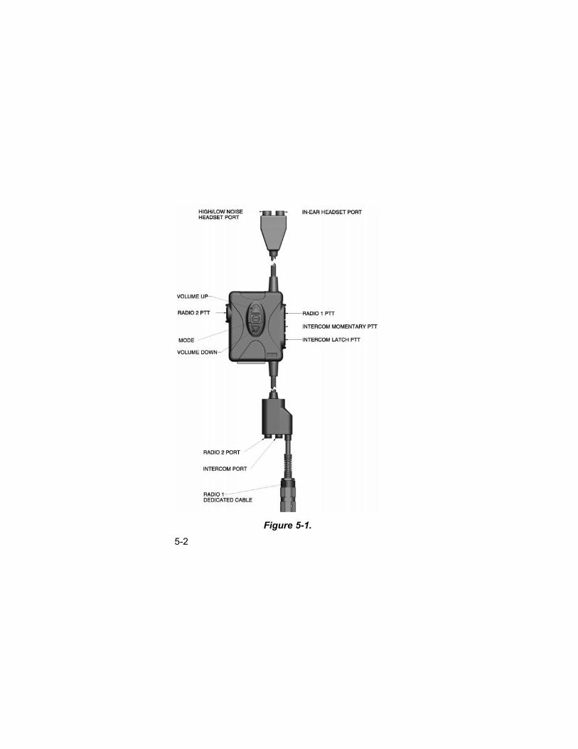
Chapter 5, CHIPS PTT Control Module
The PTT Control Module is the central component of the CHIPS Communications System. The PTT Control Module integrates and controls the communication headsets and radio/intercomconnections.
5-1
Do not mix units with different areaclassifications. All units
Figure 5-1.5-2

5-3
Port and Button Descriptions
1. Two-Port Headset Junction Block
The two-port headset junction block accommodates:
• a High Noise Circum-Aural headset
• a Low Noise headset and
• a High Noise In-Ear headset.
• The port with the Red dot indicator accepts aHigh Noise headset or a Low Noise headset.
The mating headset connectors also have thisRed dot for port identification and quickconnector alignment and mating.
• The port with the White dot indicator accepts theHigh Noise In-Ear headset.
The mating High Noise In-Ear headsetconnectors also have this White dot for portidentification and quick connector alignment andmating.
• The connector ports are keyed to prevent aheadset from being plugged into the wrong port.

2. Three-Port Radio/Intercom Junction Block
The three-port Radio/Intercom junction block is theinterface for two radios and a VIC-3/Intercom system.The radios, VIC-3 or Intercom can be used in any combination.
• The dedicated cable with the six-pin Audioconnector is the Radio 1 port.
• The port with the White dot indicator is the Radio2 port. This port accepts a radio cable with a six-Pin Audio connector. The mating connectoron the radio cable also has a White dot indicatorfor ease of identification for proper mating.
• The center port with the Red dot indicator is theVIC-3/Intercom port. This port accepts a VIC-3interface cable (terminated with an AP-107 plug)or an Intercom cable (terminated with a U-174type plug).
Both the VIC-3 cable and Intercom cable haveRed dot indicators for easy identification andmating to the corresponding junction block port.
• The connector ports are keyed to preventplugging a radio cable into the center Intercom port or plugging a VIC-3/Intercom cable into the radio port.
5-4

3. Radio 1 PTT Button
If Radio 1 is connected to the PTT box:
• When pushed and held, this button activates theRadio 1 Push-To-Talk transmit function.
4. Radio 2 PTT Button
If Radio 2 is connected to the PTT box:
• When pushed and held, this button activates theRadio 2 PTT transmit function.
5. VIC-3 Momentary PTT Button
When the PTT box is connected to a VIC-3 system:
• When pushed and held, this button activates theVIC-3 Radio PTT transmit function or the VIC-3 Intercom PTT transmit function, according to settings on the VIC-3 FFCS (Full Function Crew Station) box located in thevehicle to which the PTT box is connected.
6. VIC-3 PTT Latch Button
When the PTT box is connected to a VIC-3 system:
• When pushed and held for three seconds, thisbutton activates the PTT latch function on theVIC-3 system.
This allows the user to talk hands-free over theVIC-3 intercom without pushing any buttons.Pushing the button again for three secondsdeactivates the latch.
5-5

7. Intercom Interface
When an Intercom cable (U-174/U type plug) isconnected to the PTT box:
• the unit provides a "hot mic" to externalequipment, allowing the equipment’s own PTTdevice, or switch, to be used.
8. Volume Up Button
• When consecutive presses are performed, the Volume Up button increases the Radio orVIC-3/Intercom listening volume for:
• a High Noise Circum-Aural headset
• a Low Noise headset or
• a High Noise In-Ear headset.
• Additionally, when an In-Ear headset is pluggedinto the PTT box:
consecutive presses of the Volume Upbutton, in conjunction with the MODE button,increases the volume of the In-Ear ambientlistening speakers.
• Pressing the Volume Up and Volume Downbutton at the same time for three seconds turnsOFF the PTT box.
5-6

9. Volume Down Button
• When consecutive presses are performed, theVolume Down button decreases the Radio orVIC-3/Intercom listening volume for:
• a High Noise Circum-Aural headset
• a Low Noise headset or
• a High Noise In-Ear headset.
• Additionally, when an In-Ear headset is pluggedinto the PTT box:
consecutive presses of the Volume Downbutton, in conjunction with the MODE button,decreases the volume of the In-Ear ambientlistening speakers.
• Pushing the Volume Up and Volume Down buttonat the same time for three seconds turns the PTTbox OFF.
5-7

10. MODE Button
The MODE button serves three functions:
a. To turn ON the PTT box, push and hold theMODE button for three seconds.
b. To turn ON/OFF the In-Ear ambient listeningfunction (if an In-Ear headset is plugged into thePTT box and the box is powered up):
• A short press of the MODE button turns ON the ambient listening feature.
• Pressing and holding the MODE button for three seconds turns OFF the ambientlistening feature.
c. To select between Radio/VIC-3/Intercom listeningvolume control and High Noise In-Ear ambientvolume control (if an High Noise In-Ear headsetis plugged into the PTT box and the box ispowered up):
• A short press of the MODE button turns ON the ambient listening feature; the Volume Up and Volume Down buttonsincrease or decrease ambient listeningfeature volume. An audio prompt "AmbientVolume" alerts user that ambient volumecontrol is selected.
5-8

• Another short press of the MODE buttonselects Radio/VIC-3/Intercom volume control;the Volume Up and Volume Down buttonsincrease or decrease the volume of any radioor intercom connected to the PTT box. Anaudio prompt, "Radio Volume", alerts userthat radio/Vic-3/Intercom volume control isselected.
• Continuous short presses of the MODEbutton cause toggling between In-Earambient volume control and In-Ear Radio/Vic-3/Intercom volume control. In each case, theaudio prompt tells user what volume controlmode is selected.
NOTE: When a High Noise or Low Noise headsetonly is plugged into the box, the MODE buttonserves only to turn ON the PTT box.
The volume control function of the MODE button functions only when an In-Ear headset is plugged into the headset junction block.
11. Pressing the VOLUME UP, VOLUME DOWN and MODE buttons at the Same Time
Pressing the VOLUME UP, VOLUME DOWN andMODE buttons at the same time forces a completePTT Box shutdown.
5-9

Mode 1: In-Ear Headset Communication System
In this mode:
• Only an In-Ear Communication System isconnected to the PTT Control Module
• Transmit and Receive communication is done viathe in-ear mics and speakers
• The ambient sound function (spy mics) iscontrolled by the MODE button, Volume Up andVolume Down buttons on the PTT box.
Mode 2:In-Ear and Circum-Aural Headset Communication System
In this mode:
• The following are connected to the PTT Control Module:• The In-Ear Headset• The High Noise Headset
• Transmit and Receive communication is done viathe in-ear bone mics and speakers
• The ambient sound function (spy mics) isobtained by routing the ambient sound spy micsignals from the High Noise Headset to the in-earspeakers. Ambient volume control is obtained byusing the volume control buttons on the HighNoise headset. In this mode, the volume controlbuttons on the PTT box are not used.
5-10

Mode 3: Circum-Aural Headset Communication System Only
In this mode:
• Only the High Noise Headset is connected to thePTT control module
• Transmit and Receive communication is done viathe boom mic and headset speakers
• The ambient sound function (spy mics) isobtained by using the spy mics located on theHigh Noise Headset. ON/OFF and Volumecontrol of ambient sound is done by using theambient sound control buttons on the High Noise headset.
Mode 4: In-Ear and Low Noise Headset
In this mode:
• The following are connected to the PTT Control Module:• The In-Ear Headset• The Low Noise Headset
• Transmit and Receive communication is done viathe in-ear bone mics and speakers
• The ambient sound function (spy mics) isobtained via the spy mics on the High Noise In-Ear headset and is controlled by the MODEbutton, Volume Up and Volume Down buttons onthe PTT box. 5-11

Mode 5: Low Noise Headset
In this mode:
• Only the Low Noise Headset is connected to thePTT Control Module
• The low noise headset speaker and boom micare used
• Ear plugs can be used to provide hearingprotection while maintaining communicationcapabilities.
Mode 6 - Failsafe Mode
In a situation where a total system failure occurs andthe PTT box appears to be “dead”:
1. Remove the In-Ear headset if it is connected.
2. Plug a High Noise or Low Noise headset into theheadset junction block.
3. Use the dedicated cable (Radio 1) on the PTTbox to connect to a radio for communication.
• The headset boom mic is used fortransmitting audio.
• Received audio is in the left headset speaker.
5-12

Mode 7: Stand-alone Circum-Aural High-noise Headset
In this mode:
• Only the High Noise Circum-Aural Headset isused, without connection to the PTT ControlModule.
• The circum-aural high noise headset is used forhearing protection and talk-through capabilitieswhen long range communications are notrequired, e.g., training shooting ranges.
Additional Functions and Features
Automatic Single Comm/Dual Comm Speaker configuration
Depending on how many radios are connected to thesystem, automatic speaker configuration occurs,which enables single comm and dual comm listening.
High Noise Headset
If a single radio (Radio 1 or Radio 2) is connected tothe PTT system:
• received audio is routed to both headsetspeakers, providing a "single comm" headset configuration.
5-13

If two radios are connected to the PTT system:
• Radio 1 received audio is heard in the left earheadset speaker and
• Radio 2 received audio is heard in the right earheadset speaker.
If two radios and a VIC-3/Intercom are connected tothe PTT box:
• Radio 1 received audio is heard in the left earheadset speaker
• Radio 2 received audio is heard in the right earheadset speaker and
• VIC-3/Intercom audio is heard in both ears.
In-Ear Headset
If a single radio (Radio 1 or Radio 2) is connected tothe PTT system:
• received audio is routed to both In-Ear speakers,providing a "single comm" headset configuration.
If two radios are connected to the PTT system:
• Radio 1 received audio is heard in the left In-Earspeaker and
• Radio 2 received audio is heard in the right In-Ear speaker.
5-14

When a VIC-3/Intercom is connected to the PTT boxwhile In-Ear speakers are used:
• all received audio is routed to the right In-Earheadset. This includes Radio 1, Radio 2, and VIC-3/Intercom audio.
Battery Run Time
Install a fresh CR123 battery after 65 hours ofcontinuous battery use; this means that the batterysupplied the power when used with radios that do notsupply power.
When the battery is low:
• a short audio burst of five beeps every fiveminutes is heard by the user.
If the battery is not changed and becomes weaker:
• the audio burst then occurs every two minutes,alerting the user that the batteries must bechanged within the next two or three hours.
Auto Shutdown
When the battery is supplying the power for the PTT box:
• If the PTT box is powered up and no button waspressed for four hours, the unit automaticallyshuts down to conserve battery power.
5-15

Voice Annunciation
Voice annunciation alerts the user when radio andintercom cables are plugged or unplugged. Voiceannunciation also aids in in-ear volume control for theambient volume and radio/intercom volume.
Battery Replacement
1. Loosen the screw holding the batterycompartment cover in place.
2. Carefully open the top cover.
3. Replace the CR123 battery using the web guideto lift the battery from the battery compartment.Install a fresh battery.
4. Replace the battery cover, making sure to seat it properly.
5. Make sure the battery cover seal is free of dirtand debris.
6. Tighten the screw loosened in step 1.
• The screw must be tightened thoroughly to ensure that the battery compartmentremains waterproof.
Maintenance
1. Make sure all connectors are free of dirt or debris.
5-16
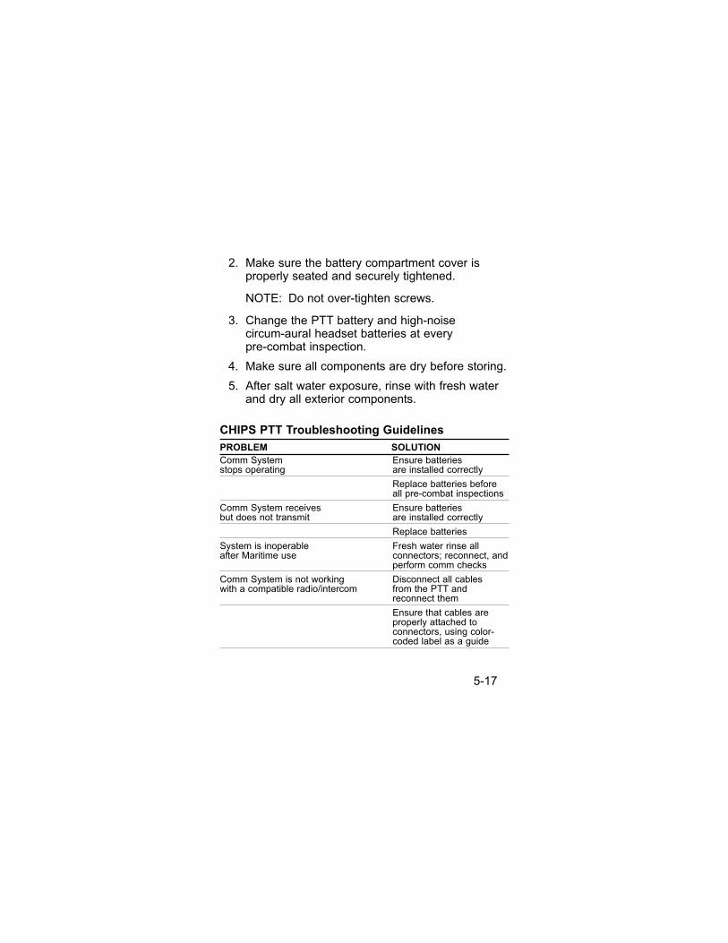
2. Make sure the battery compartment cover isproperly seated and securely tightened.
NOTE: Do not over-tighten screws.
3. Change the PTT battery and high-noise circum-aural headset batteries at every pre-combat inspection.
4. Make sure all components are dry before storing.
5. After salt water exposure, rinse with fresh waterand dry all exterior components.
CHIPS PTT Troubleshooting Guidelines
PROBLEM SOLUTION
Comm System Ensure batteries stops operating are installed correctly
Replace batteries before all pre-combat inspections
Comm System receives Ensure batteriesbut does not transmit are installed correctly
Replace batteries
System is inoperable Fresh water rinse allafter Maritime use connectors; reconnect, and
perform comm checks
Comm System is not working Disconnect all cableswith a compatible radio/intercom from the PTT and
reconnect them
Ensure that cables are properly attached to connectors, using color-coded label as a guide
5-17

Fully Integrated System
• If mission requires hearing protection, use theHigh-Noise Circum-Aural Headset or the High-Noise In-Ear Communication System.
Use double hearing protection (high-noisecircum-aural headset and high noise in-earcommunication) when headsets are usedin very high noise environments, such astrack vehicles, for eight hours or longer;otherwise, hearing damage will occur.
• Determine if:
• the CHIPS Communication System will beused in a single radio or dual radio
• intercom communications are required.
• Connect Low- Or High-Noise CommunicationHeadset(s) to the PTT using the quick disconnectconnector(s).
• Connect the PTT to the radio using appropriateradio cable connectors.
• The Single-comm PTT has the fixed primary cable.
• Dual-comm radio and intercom cables can beadded to the suite using quick-disconnects,expanding the system to Dual and CHIPScommunication capabilities.
" CAUTION
5-18

Figure 5-2.
5-19
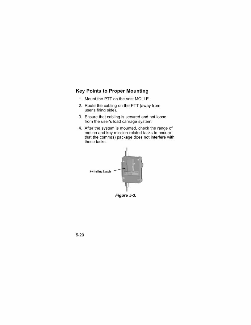
Key Points to Proper Mounting
1. Mount the PTT on the vest MOLLE.
2. Route the cabling on the PTT (away from user's firing side).
3. Ensure that cabling is secured and not loosefrom the user's load carriage system.
4. After the system is mounted, check the range ofmotion and key mission-related tasks to ensurethat the comm(s) package does not interfere withthese tasks.
Figure 5-3.
5-20

Mounting Checklist
1. Is the system mounted on your non-firing side?
2. Is the cabling routed away from the firing sideand away from equipment needed for yourmission? Use flex-ties and rigger tape,if necessary.
3. Do you have access to both push-to-talk buttonson the CHIPSm box?
4. Do you have full range of motion while wearingall gear needed for your mission?
5. Have you used tie-downs and routed cables toprevent snagging hazards?
6. Have you considered the best way to place androute this equipment? It may take a few triesbefore the kit is placed correctly for the individual user.
5-21

Chapter 6,CHIPS Communication SystemSpecifications
Specifications
System Guaranteed when temperature of use is betweenPerformance -40°F to +140°F
Storage Between -40°F to +160°FTemperature
Relative Tolerated from 0 to 100%Humidity
Water Rated for IP67Resistant
Typical 65 hoursBattery LIfe
Weight Headset Circum-Aural 445 g (.98 lbs.)In-Ear 363 g (.80 lbs.)Low-Noise 91 g (.20 lbs.)
PTT 372 g (.82 lbs.)ControlModuleWith Battery
Interface PRC Connector 91 g (.20 lbs.)Cables VIC 3 Cable 73 g (.16 lbs.)withConnectors
Carry Bag 735 g (1.62 lbs.)
Complete 2,170 g (4.8 lbs.)System
Hearing Above 82 dBProtection
Ambient Below 82 dBNoise Amplification
NOTE: Inspect system before each use. If any deficiency is found, replace damaged item before use.
6-1

General Communication System Warranty
1. Warranty- Seller warrants that this product willbe free from mechanical defect or faultyworkmanship for a period of two years from dateof shipment, provided it is maintained and usedin accordance with Seller's instructions and/orrecommendations. This warranty does not applyto expendable or consumable parts whosenormal life expectancy is less than one (1) yearsuch as, but not limited to, non-rechargeablebatteries, filament units, filter, lamps, fuses etc.The Seller shall be released from all obligationsunder this warranty in the event repairs ormodifications are made by persons other than itsown or authorized service personnel or if thewarranty claim results from physical abuse ormisuse of the product. No agent, employee orrepresentative of the Seller has any authority tobind the Seller to any affirmation, representationor warranty concerning the goods sold under thiscontract. Seller makes no warranty concerningcomponents or accessories not manufactured bythe Seller, but will pass on to the Purchaser allwarranties of manufacturers of such components.THIS WARRANTY IS IN LIEU OF ALL OTHERWARRANTIES, EXPRESSED, IMPLIED ORSTATUTORY, AND IS STRICTLY LIMITED TOTHE TERMS HEREOF. SELLERSPECIFICALLY DISCLAIMS ANY WARRANTYOF MERCHANT ABILITY OR OF FITNESS FORA PARTICULAR PURPOSE.
6-2

2. Exclusive Remedy- It is expressly agreed thatPurchaser's sole and exclusive remedy forbreach of the above warranty, for any tortiousconduct of Seller, or for any other cause ofaction, shall be the repair and/or replacement atSeller's option, of any equipment or parts thereof,which after examination by Seller is proven to bedefective. Replacement equipment and/or partswill be provided at no cost to Purchaser, F.O.B.Seller's Plant. Failure of Seller to successfullyrepair any non-conforming product shall notcause the remedy established hereby to fail of itsessential purpose.
3. Exclusion of Consequential Damage-Purchaser specifically understands and agreesthat under no circumstances will seller be liableto purchaser for economic, special, incidental orconsequential damages or losses of any kindwhatsoever, including but not limited to, loss ofanticipated profits and any other loss caused byreason of non-operation of the goods. Thisexclusion is applicable to claims for breach ofwarranty, tortious conduct or any other cause ofaction against seller.
Contact:
• MSA Customer ServiceP.O. Box 426Pittsburgh, PA 15230-0426
• Commercial Phone:
• In U.S.: 1-800-MSA-2222
• From outside U.S.: 412-967-3000.
6-3
Unit Warranty Procedures
The unit:
• may send CHIPS Communication Systems madeunserviceable due to fair wear and tear or anexpired warranty period to MSA for repair or replacement.
• must include completed work requests form(such as a DA Form 2407 maintenance requestor similar component work request form) when shipping to SOFSA.
Maintenance Request Minimum Information
• Unit designation
• Unit point of contact (POC)
• Unit shipping address
• Telephone number of POC
• Nomenclature of CHIPS Communication System item
• Description of component failure or damage.
6-4

Parts LIst
PART NO. DESCRIPTION
10093514 Radio/Intercom Interface Junction Block
10093513 Headset Interface Junction Block
10088357 In-Ear Headset
10094783 Low Noise Headset, Dual Bone Speakers
10102430 Low Noise Headset Mic Wind Guard, 10 per pkg.
10102619 High Noise Circum-Aural Headset Boom Mic WindGuard
10095584 Clothing Clip, Rotating
10102621 In-Ear Foam Replacement Pack, Standard
10102617 Large Left Soft Spring
10102616 Large Right Soft Spring
10102615 Small Left Soft Spring
10102614 Small Right Soft Spring
154008A High Noise Circum-Aural Foam Hygiene Kit
10082377 High Noise Circum-Aural Gel Hygiene Kit
10088358 High Noise Circum-Aural Headset, Neckband, Electret Mic On Left, Foam Seal
10088359 High Noise Circum-Aural Headset, Neckband, Dynamic Mic On Left, Foam Seal
10088360 High Noise Circum-Aural Headset, Neckband, Electret Mic On Left, Gel Seal
10099068 High Noise Circum-Aural Headset, Neckband, Dynamic Mic On Left, Gel Seal
6-5

10099069 High Noise Circum-Aural Headset, Neckband, Electret Mic On Right, Foam Seal
10099070 High Noise Circum-Aural Headset, Neckband, Dynamic Mic On Right, Foam Seal
10099071 High Noise Circum-Aural Headset, Neckband, Electret Mic On Right, Gel Seal
10099072 High Noise Circum-Aural Headset, Neckband, Dynamic Mic On Right, Gel Seal
10098930 High Noise Circum-Aural Headset, Headband, Electret Mic On Left, Foam Seal
10099061 High Noise Circum-Aural Headset, Headband, Dynamic Mic On Left, Foam Seal
10099062 High Noise Circum-Aural Headset, Headband, Electret Mic On Left, Gel Seal
10099063 High Noise Circum-Aural Headset, Headband, Dynamic Mic On Left, Gel Seal
10099064 High Noise Circum-Aural Headset, Headband, Electret Mic On Right, Foam Seal
10099065 High Noise Circum-Aural Headset, Headband, Dynamic Mic On Right, Foam Seal
10099066 High Noise Circum-Aural Headset, Headband, Electret Mic On Right, Gel Seal
10099067 High Noise Circum-Aural Headset, Headband, Dynamic Mic On Right, Gel Seal
6-6