chillventa r404a alternatives r kebby oct14 · topic / agenda current and future low gwp...
TRANSCRIPT

Exhibition Hall 4AExhibition Hall 4A
Current and Future Low GWP Fluidsfor Commercialfor Commercial
Refrigeration Applications
Technical Programme
1

Topic / Agenda
Current and Future Low GWP FluidsCurrent and Future Low GWP Fluidsfor Commercial Refrigeration Applications
S. Yana Motta, G. Pottker, M. Spatz, R. KebbyBuffalo Research LaboratoryBuffalo Research Laboratory
Introduction Evaluation and Handling Issues for Blends of refrigerants Compressor Calorimeter
Fractionation of blends during leak events
System Evaluations of R-404A Replacements Non-Flammable options (N-40 / R448A)
Mild-Flammable options (L-40)
Overall Environmental Impact
Concluding Remarks
2

Refrigerants: Reduced/Lowest GWP OptionsHFO Molecules (Ultra-Low GWP)
Examples of Applications Current Product Non-Flammable
(ASHRAE A1)Mildly Flammable
(ASHRAE A2L) Application Icons
MAC, Vending, Refrigerators
Solstice® yf GWP<1R 1234 yfRefrigerators HFC-134a
GWP-1430R-1234 yf
Chillers, Cascade,Refrigerators
Solstice® ze GWP<1R-1234 ze
C t if l Chill R-123 Solstice® zd GWPCentrifugal Chillers R 123GWP-77
Solstice® zd GWP 1
HFO Blends (Low GWP)
Examples of Applications Current Products
Solstice N Series Reduced GWP
Option Non-Flammable (ASHRAE A1)
Solstice L Series Lowest GWP Option
Mildly Flammable (ASHRAE A2L)
Application Icons
( )
Chillers, Medium Temp Refrigeration
HFC-134aGWP-1430
N-13 GWP ~600 (R-450A)
Stationary A/C, Refrigeration
HCFC-22GWP 1810 N-20 GWP <1000 L-20 GWP <300
(R 444B)Refrigeration GWP-1810 (R-444B)
Low-and Med-Temp Refrigeration
R-404AGWP-3922
N-40 GWP ~1380 (R-448A) HDR110 GWP <150
Stationary A/C R 410A L 41 GWP <600
3
Stationary A/C Applications
R-410AGWP-2088
L-41 GWP <600 (R-447A)

Compressor EvaluationsEvaporator
S d P
ExpansionValve
Secondary Pressure
SecondaryFluid
OutletT and P
DischargeP, T
SuctionP, T
Heater Control
CompressorOil Separator
CondenserWateroutlet
P, T,
Power Oil SeparatorPowerMeasurement
OutletT and P
WaterInlet
Employed a fully-instrumented 50k BTUH Secondary-Fluid Calorimeter. Tested a 38.3 kBTUH semihermetic compressor, using R404A, R407F and N-40.
T and P
Operating Conditions as required by AHRI standard 540: Evaporating temperatures of -40ºF and -25ºF; Condensing temperatures of 70ºF, 90F, and 105ºF Ambient temperature of 95ºF, saturated liquid at the inlet of expansion device.
4
Used “Dew” pressures and a fixed value of 65ºF gas temperature at the suction.

N-40 (R-448A) vs R404A: Standard Calorimeter Conditions
110%Flow-Evap Capacity Efficiency
90%
100%
%)
70%
80%
s R
404A
(%
50%
60%
N40
vs
40%
50%
‐25F/70F ‐25F/90F ‐25F/105F
When evaluated using Dew pressures and 65ºF suction gas temperature, N40 shows low capacity (84% to 86% relative to R404A) and similar efficiency to R404A.
The use of a fixed suction gas temperature (65ºF) would also affect compressor efficiency as
5
actual suction temperatures are significant lower.

N-40 (R-448A) vs R404A: Useful Cooling for 10ºF Superheat
120%
Flow-Evap Capacity Efficiency
90%
100%
110%A
(%)
70%
80%
90%
vs
R40
4A ~10% up
50%
60%N40
No Change
C t d th li it t t l h t t t tl t f 10ºF
40%
‐25F/70F ‐25F/90F ‐25F/105F
Corrected the cooling capacity to use actual superheat at evaporator outlet of 10ºF. Refrigerants with high contents of R125 (like R404A) have low latent heat and benefit from
calculating the refrigerating effect at 65ºF suction temperature. Effects are as high as 10% in both capacity and efficiency.
6

N-40 (R-448A) vs R404A: Using 10ºF SH + Average Pressures
110%
120%Flow-Evap Capacity Efficiency
90%
100%4A
(%)
~20% up
70%
80%
40 v
s R
404
10% up
40%
50%
60%N4 ~10% up
40%
‐25F/70F ‐25F/90F ‐25F/105F
The use of Dew pressures penalize blends with glide in compressor calorimeter evaluations Using average pressure and realistic degree of superheat results in capacities and efficiencies similar Using average pressure and realistic degree of superheat results in capacities and efficiencies similar
to values obtained in tests of refrigeration systems. Effects are as high as 20% when both average pressures and useful superheat (10ºF) are used. Other effects of testing compressor at high suction temperatures (volumetric and isentropic efficiencies)
h ld l b i ti t d
7
should also be investigated.

Learnings from Compressor Calorimeter Evaluations
SystemSystem
P fP f
SystemSystem
PerformancePerformancePerformancePerformance
Comp.Comp.
RatingRating
Comp.Comp.
RatingRating
-25ºF SST25 F SST
105ºF SDT
Compressor rating data should be used with caution for blends with glide.Actual system performance can be significantly different.
8
y p g yData suggests review of Testing Conditions in AHRI Standard 540
Fractionation of Blends during Leak EventsVapor Discharge Line
Suction Line
C
Middle Condenser
CondenserEvaporator
Compressor
Expansion Li id
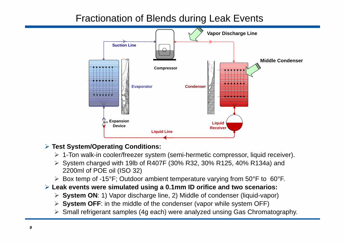
Test System/Operating Conditions:
ExpansionDevice
Liquid Line
Liquid Receiver
180
y p g 1-Ton walk-in cooler/freezer system (semi-hermetic compressor, liquid receiver). System charged with 19lb of R407F (30% R32, 30% R125, 40% R134a) and
2200ml of POE oil (ISO 32) B t f 15°F O td bi t t t i f 50°F t 60°F Box temp of -15°F; Outdoor ambient temperature varying from 50°F to 60°F.
Leak events were simulated using a 0.1mm ID orifice and two scenarios: System ON: 1) Vapor discharge line, 2) Middle of condenser (liquid-vapor) System OFF: in the middle of the condenser (vapor while system OFF)
9
System OFF: in the middle of the condenser (vapor while system OFF) Small refrigerant samples (4g each) were analyzed unsing Gas Chromatography.
System ON: Vapor leak from the Discharge Line
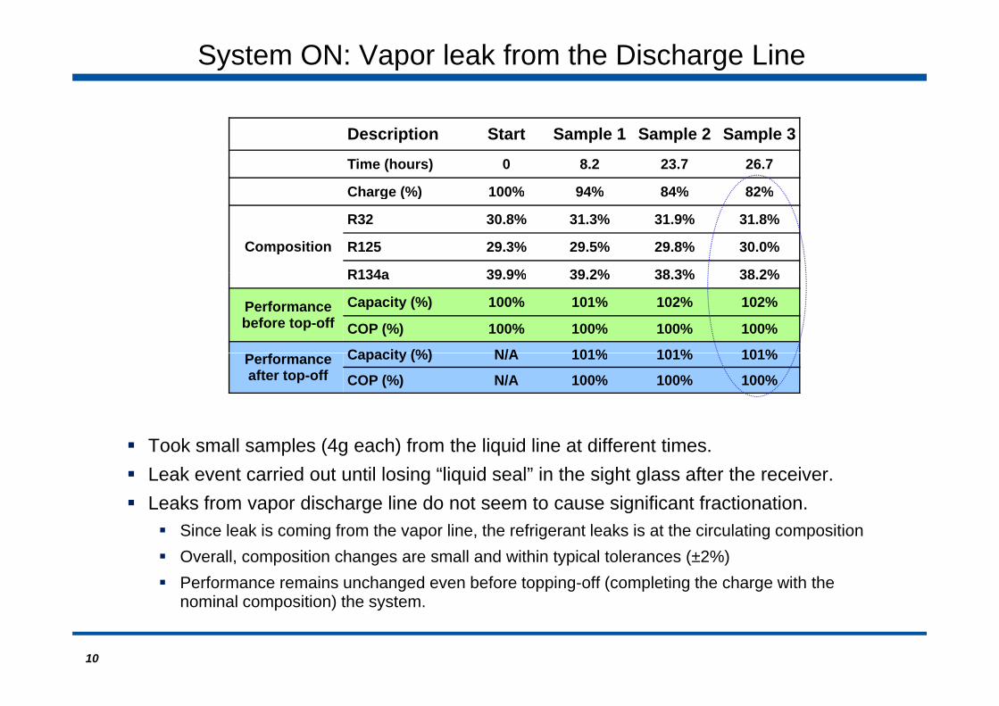
Description Start Sample 1 Sample 2 Sample 3
Time (hours) 0 8.2 23.7 26.7
Charge (%) 100% 94% 84% 82%Charge (%) 100% 94% 84% 82%
Composition
R32 30.8% 31.3% 31.9% 31.8%
R125 29.3% 29.5% 29.8% 30.0%
R134a 39 9% 39 2% 38 3% 38 2%R134a 39.9% 39.2% 38.3% 38.2%
Performance before top-off
Capacity (%) 100% 101% 102% 102%
COP (%) 100% 100% 100% 100%
Capacity (%) N/A 101% 101% 101%Performance after top-off
Capacity (%) N/A 101% 101% 101%
COP (%) N/A 100% 100% 100%
Took small samples (4g each) from the liquid line at different times. Leak event carried out until losing “liquid seal” in the sight glass after the receiver. Leaks from vapor discharge line do not seem to cause significant fractionation.g g
Since leak is coming from the vapor line, the refrigerant leaks is at the circulating composition Overall, composition changes are small and within typical tolerances (±2%) Performance remains unchanged even before topping-off (completing the charge with the
10
nominal composition) the system.

System ON: Two-phase leak from the Condenser
Description Start Sample 1 Sample 2 Sample 3
Time (hours) 0 5.5 22.1 28.2
Charge (%) 100% 94% 78% 72%g ( )
Composition
R32 30.8% 29.5% 28.3% 27.7%
R125 29.5% 28.7% 28.0% 27.7%
R134a 39.8% 41.8% 43.7% 44.6%R134a 39.8% 41.8% 43.7% 44.6%
Performance before top-off
Capacity 100% 98% 96% 95%
COP 100% 100% 100% 100%
Performance Capacity (%) N/A 98% 97% 96%Performance after top-off
Capacity (%) N/A 98% 97% 96%
COP (%) N/A 100% 100% 100%
Took small samples (4g each) from the liquid line at different times. Leak event carried out until losing “liquid seal” in the sight glass after the receiver. Two-phase leaks seem to cause slightly larger changes in composition.p g y g g p
For 20% charge loss, overall composition is still within typical tolerances (±2%) Changes in performances within experimental error (±5%) If the charge is topped-off, composition and performance become even closer to original
11
g pp , p p gvalues.

System OFF: Slow Vapor leaks
Description Start Sample 1 Sample 2
Time (hours) 0 20.3 37.4
Charge (%) 100% 79% 62%g ( )
Composition
R32 30.0% 29.2% 27.7%
R125 30.1% 29.8% 28.7%
R134a 39.9% 41.1% 43.6%R134a 39.9% 41.1% 43.6%
Performance before top-off
Capacity 99% 99% 96%
COP 100% 100% 100%
Performance Capacity (%) N/A 99% 98%
A slow vapor leak with the system OFF is known as the “worst case” scenario.
Performance after top-off
Capacity (%) N/A 99% 98%
COP (%) N/A 100% 100%
Followed special procedure with these typical steps: Turned system OFF and allowed 4 days to settle before starting leak. Started leak event which lasted between 17h to 20h. Stop leak and turn system ON to take sample from the liquid line.
For 20% charge loss, composition is still within typical tolerances (±2%) For the largest charge loss, performances is still within experimental error (±5%)
12
After top-off, composition and performance become even closer to original values.

Refrigeration System Test Apparatus
2.2 kW semi-hermetic condensing unit with evaporator for walk-in freezer/cooler.U d l ti li (t i l f k t ) t ki i t t ti Used long connecting lines (typical of supermarkets), taking into account suction pressure drop and temperature rise effects.
Operating Conditions: Low temperature:
-15F and 0F Box Temperature; 55F, 75ºF and 95F Outdoor Ambient Temperature Medium Temperature:
13
35F and 50F Box Temperature; 55F, 75ºF and 95F Outdoor Ambient Temperature

Non-Flammables: Performance at Low Temperature
Low Temperature conditions: 95ºF Outdoor 15ºF BoxLow Temperature conditions: 95ºF Outdoor, -15ºF Box
Experimental Experimental UncertaintyUncertainty±±5%5%
Supermarket Freezer Cases (LT)
N-40 (R-448) performance in System evaluations match “corrected” Compressor data Similar Results were obtained for commercially available R407F
14
Similar Results were obtained for commercially available R407F

Non-Flammables: Performance at Medium Temperature
M di T t diti 95ºF O td 35ºF BMedium Temperature conditions: 95ºF Outdoor, 35ºF Box
Experimental Experimental UncertaintyUncertainty±±5%5%
Supermarket/Deli Cases (MT)Supermarket/Deli Cases (MT)
Results for Medium Temperature Refrigeration are also similar O ll N 40 (R448A) id ll t E Effi i
15
Overall, N-40 (R448A) provide excellent Energy Efficiency

Mild Flammables: PerformanceLow Temperature conditions: 95ºF Outdoor, -15ºF BoxMedium Temperature conditions: 95ºF Outdoor, 35ºF Box
ExperimentalExperimental4A Experimental Experimental UncertaintyUncertainty
±±5%5%
ativ
e to
R40
4L-
40 R
ela
GWP reduction of over 90% relative to R-404A drastically reduces direct emissions Superior energy efficiency relative to R-404A further reduces environmental impact.
16
L-40 can be used in the high stage of Cascade (with CO2) and Secondary-Fluid!

Environmental Impact - LCCP Analysis
AssumptionsYearly calculations for a store located in Atlanta, GA45000 ft2 (36% LT, 64% MT), 3200lb of R404A15% annual leak rate (DX Systems)
The use of N-40 (R-448A) and even R407F, allows considerable reduction of environmental impact when retrofitting existing systems (~50%).
Among current DX technologies, distributed systems using N-40 (R-448A) produce
17
g g , y g ( ) penvironmental impact similar to more sophisticated technologies (cascade and pumped CO2).

Concluding Remarks
Evaluations of blends in compressor calorimeters showsignificant difference to actual system performance. Possible revisions of AHRI standard 540 for compressor calorimeter p
testing suggested
Fractionation Study under realistic “leak” events shows little i t t l t fimpact on actual system performance. Effects of actual working conditions (turbulence/mixing) and oil presence
seem to attenuate composition change.
N-40 (R-448A) provides higher Energy-Efficiency with Reduced-GWP Non-flammable (A1) allows use in existing systems that use R404ANon flammable (A1) allows use in existing systems that use R404A LCCP analysis demonstrate that superior Energy-Efficiency and lower
GWP (~1300) reduce the carbon footprint of current and future systems.
Further work is needed to fully explore these applications. Additional performance and “field” evaluations planned. More detailed LCCP evaluations are also suggested.
18
Exhibition Hall 4AExhibition Hall 4A
THANK YOU
Questions?
Technical Programme
19