chevron canopy - lsi...
TRANSCRIPT

Please review site plans before proceeding. Contact LSI Graphic Solutions Plus
Customer Service at 1-(800) 678-2001 for installation support.
Read through all of the instructions prior to beginning installation, and verify (using
the packing list) that all parts have been received and are in good condition.
INSTALLATION
SHEET 1 OF 7INSTRUCTIONS: 5100234A REV. 08/04/2009
JDE# 328307
CHEVRON CANOPY:
GUIDELSI LED Lighting for Downlight
and Accent Band
(Effective April 2008)

SHEET 2 OF 7INSTRUCTIONS: 5100234B REV. 08/04/2009
INTRODUCTION
The LSI LED Downlighter and Accent light are designed to provide a blue wash to the fascia for the
Chevron Image Refresh released in 2006. This product is patent pending under Provisional Number
60-761943. Please refer to the Chevron Conversion manual for the site level and illumination
guidelines for your station.
LSI provides LED assemblies and power supplies with the necessary cables to illuminate the
downlighter and accent band. These are provided as modular assemblies that can be linked to
provide the necessary linear lighting to fit your requirements, with a field customized length on each
side to fit site conditions. Please read through all the instructions before beginning your installation to
be sure that this product is installed properly and will meet all Chevron guidelines as well as National
Electric Code, Underwriters Laboratory listing and any state or local codes required. Numerous
options and variations are possible, but the positioning and installation of this element is critical to
proper function.
Note there is a quick install guide provided first if these are being installed in existing canopies where
the hood and accent have already been constructed. A full canopy system installation guide is
available from LSI - using brackets, hoods, accent bands and endcaps provided by LSI, or using
complete canopy kits provided by LSI, as well as options for power supplies and installation kits.
Please contact LSI Customer Service if you need the full system installation guide.
SHORTAGES OR FREIGHT DAMAGE CLAIMS
All shortages must be reported to LSI Graphic Solutions Plus within seven days after receipt of
material. Inspect shipment before letting the carrier leave. Buyer is responsible for placing claim
against the damage or lost goods during shipment. Products damaged during shipment require a
freight claim to be filed with freight carrier within seven days of receipt of goods on site. Freight
damaged goods are not covered under LSI's warranty.
SHEET 3 OF 7INSTRUCTIONS: 5100234C.dwg REV. 08/04/2009
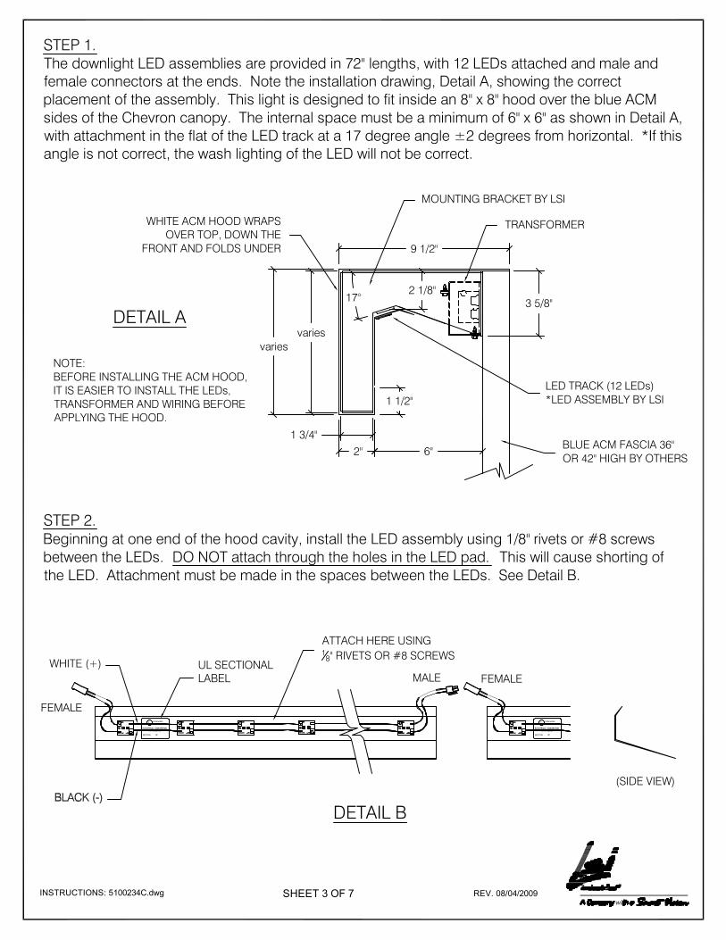
STEP 1.The downlight LED assemblies are provided in 72" lengths, with 12 LEDs attached and male and
female connectors at the ends. Note the installation drawing, Detail A, showing the correct
placement of the assembly. This light is designed to fit inside an 8" x 8" hood over the blue ACM
sides of the Chevron canopy. The internal space must be a minimum of 6" x 6" as shown in Detail A,
with attachment in the flat of the LED track at a 17 degree angle ±2 degrees from horizontal. *If this
angle is not correct, the wash lighting of the LED will not be correct.
LED TRACK (12 LEDs)
*LED ASSEMBLY BY LSI
3 5/8"
1 3/4"
varies
9 1/2"
2"
1 1/2"
varies
2 1/8"17°
6"
MOUNTING BRACKET BY LSI
WHITE ACM HOOD WRAPS
OVER TOP, DOWN THE
FRONT AND FOLDS UNDER
BLUE ACM FASCIA 36"
OR 42" HIGH BY OTHERS
DETAIL A
NOTE:
BEFORE INSTALLING THE ACM HOOD,
IT IS EASIER TO INSTALL THE LEDs,
TRANSFORMER AND WIRING BEFORE
APPLYING THE HOOD.
STEP 2.
Beginning at one end of the hood cavity, install the LED assembly using 1/8" rivets or #8 screws
between the LEDs. DO NOT attach through the holes in the LED pad. This will cause shorting of
the LED. Attachment must be made in the spaces between the LEDs. See Detail B.
Underwriters
Laboratories Inc.
UL
ELECTRICAL SIGN SECTION
No. AB 123456
SECTION OF
DETAIL B
FEMALE
MALEUL SECTIONAL
LABEL
WHITE (+)
(SIDE VIEW)
Underwriters
Laboratories Inc.
UL
ELECTRICAL SIGN SECTION
No. AB 123456
SECTION OF
ATTACH HERE USING18" RIVETS OR #8 SCREWS
TRANSFORMER
FEMALE
SHEET 4 OF 7INSTRUCTIONS: 5100234D.dwg REV. 08/04/2009
FEMALEMALE
1/4"
OVERLAP
(OPTIONAL)
DETAIL C
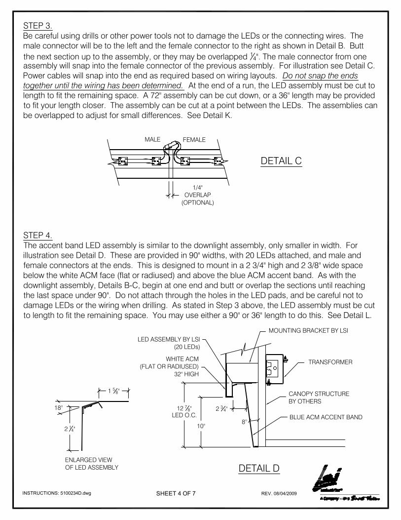
STEP 3.Be careful using drills or other power tools not to damage the LEDs or the connecting wires. The
male connector will be to the left and the female connector to the right as shown in Detail B. Butt
the next section up to the assembly, or they may be overlapped 14". The male connector from one
assembly will snap into the female connector of the previous assembly. For illustration see Detail C.
Power cables will snap into the end as required based on wiring layouts. Do not snap the ends
together until the wiring has been determined. At the end of a run, the LED assembly must be cut to
length to fit the remaining space. A 72" assembly can be cut down, or a 36" length may be provided
to fit your length closer. The assembly can be cut at a point between the LEDs. The assemblies can
be overlapped to adjust for small differences. See Detail K.
BLUE ACM ACCENT BAND
LED ASSEMBLY BY LSI
(20 LEDs)
CANOPY STRUCTURE
BY OTHERS
MOUNTING BRACKET BY LSI
WHITE ACM
(FLAT OR RADIUSED)
32" HIGH
8°
2 34"12 7
8"LED O.C.
10"
DETAIL D
STEP 4.The accent band LED assembly is similar to the downlight assembly, only smaller in width. For
illustration see Detail D. These are provided in 90" widths, with 20 LEDs attached, and male and
female connectors at the ends. This is designed to mount in a 2 3/4" high and 2 3/8" wide space
below the white ACM face (flat or radiused) and above the blue ACM accent band. As with the
downlight assembly, Details B-C, begin at one end and butt or overlap the sections until reaching
the last space under 90". Do not attach through the holes in the LED pads, and be careful not to
damage LEDs or the wiring when drilling. As stated in Step 3 above, the LED assembly must be cut
to length to fit the remaining space. You may use either a 90" or 36" length to do this. See Detail L.
1 58"
2 14"
18°
ENLARGED VIEW
OF LED ASSEMBLY
TRANSFORMER

SHEET 5 OF 7INSTRUCTIONS: 5100234E.dwg REV. 08/04/2009
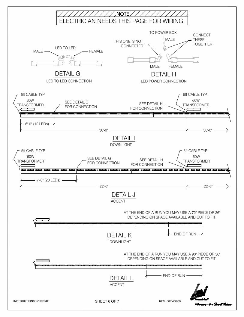
STEP 5.LSI provides 60W transformers to be used with these LED assemblies. Each LED draws one watt,
so up to 60 LEDs can be powered per circuit. For the downlight, 5 sections (60W or 30ft), can be
powered by each circuit. For the accent, three sections (60 LEDs or 22ft 6") can be powered by
each circuit. 5 ft cables are provided with the power supply. See (Detail I) for downlighter and
(Detail J) for accent.
STEP 6.Enclosure boxes and wiring bushings comply with NEC and UL requirements. The installer must
connect the provided conduit to 120 VAC 60 Hz circuit in compliance with NEC and local codes.
STEP 7.Both the downlight and accent band use the same style power supply, but due to placement,
separate power supplies are used. The power supply for the downlighter can be mounted under the
hood, attached to the blue ACM, and serviced from below (See Detail F). The power supply should
be mounted within four feet of the beginning of each run, and primary power supplied through the
ACM panel. Optionally, the power supply can be mounted on the back side of the ACM or on the
canopy structure within four feet of the connection. Due to space constraints, the accent band
power supply will not fit inside the cavity of the accent, and must be mounted on the back side of
the return or on the canopy structure. Be sure to keep the power supply out of water accumulation
areas, and to provide adequate protection for cables. The power supply must be mounted with the
cover facing down as shown (See Detail E), with adequate clearance to remove the cover for
servicing the power supply.
DETAIL E
TRANSFORMER
DETAIL FTO SERVICE THE TRANSFORMER, IN
EITHER THE ACCENT BAND OR THE
DOWNLIGHTER, YOU MUST UNFASTEN THE
SCREWS AND REMOVE THE COVER.
TRANSFORMER
ACCENT DOWNLIGHT
SHEET 6 OF 7INSTRUCTIONS: 5100234F REV. 08/04/2009
6'-0" (12 LEDs)
30'-0"
60W
TRANSFORMER
60W
TRANSFORMER
30'-0"
5ft CABLE TYP5ft CABLE TYP
SEE DETAIL H
FOR CONNECTION
7'-6" (20 LEDs)
22'-6"
SEE DETAIL G
FOR CONNECTION
60W
TRANSFORMER
60W
TRANSFORMER
22'-6"
5ft CABLE TYP5ft CABLE TYP
SEE DETAIL H
FOR CONNECTION
DETAIL I
DETAIL J
DOWNLIGHT
ACCENT
END OF RUNDETAIL K
DETAIL L
DOWNLIGHT
ACCENT
END OF RUN
AT THE END OF A RUN YOU MAY USE A 90" PIECE OR 36"
DEPENDING ON SPACE AVAILABLE AND CUT TO FIT.
NOTENOTENOTENOTE
ELECTRICIAN NEEDS THIS PAGE FOR WIRING.
DETAIL G
TO POWER BOX
LED TO LED
LED TO LED CONNECTION
DETAIL HLED POWER CONNECTION
FEMALEMALE
MALE
MALE FEMALE
CONNECT
THESE
TOGETHERTHIS ONE IS NOT
CONNECTED
AT THE END OF A RUN YOU MAY USE A 72" PIECE OR 36"
DEPENDING ON SPACE AVAILABLE AND CUT TO FIT.
SEE DETAIL G
FOR CONNECTION
SHEET 7 OF 7INSTRUCTIONS: 5100234G REV. 08/04/2009
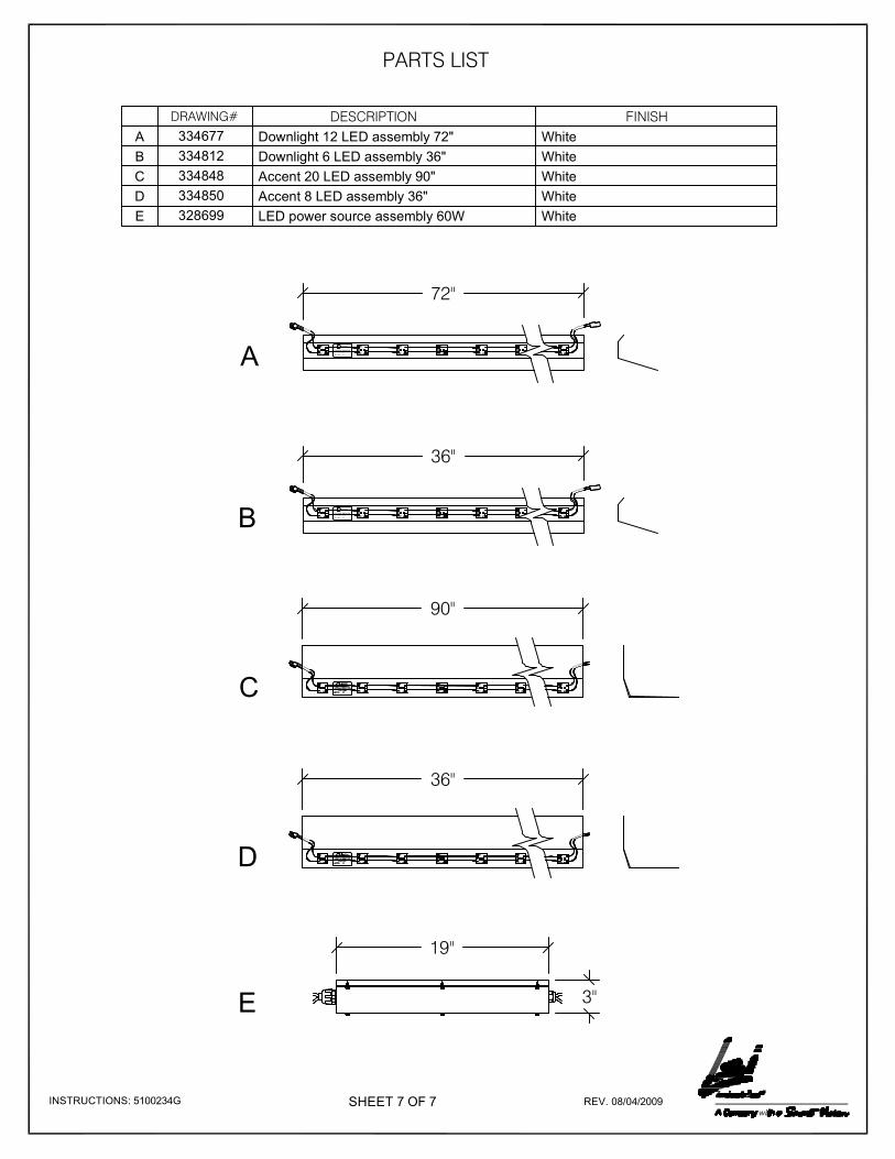
DESCRIPTION FINISH
Downlight 12 LED assembly 72"A
B
C
D
DRAWING#
334677
E
Accent 20 LED assembly 90"334848
LED power source assembly 60W White
PARTS LIST
328699
Underwriters
Laborator ies Inc.
UL
ELECT RICAL SIGN SECTION
No. AB 123456
SECT ION OFA
72"
C
90"
Downlight 6 LED assembly 36"
Accent 8 LED assembly 36"
334812
334850
Underwriters
Laborator ies Inc.
UL
ELECT RICAL SIGN SECTION
No. AB 123456
SECT ION OFB
36"
D
36"
19"
3"E
White
White
White
White