chemo-mechanical modeling for prediction of alkali silica
TRANSCRIPT

HAL Id: hal-01724667https://hal.insa-toulouse.fr/hal-01724667
Submitted on 20 Feb 2019
HAL is a multi-disciplinary open accessarchive for the deposit and dissemination of sci-entific research documents, whether they are pub-lished or not. The documents may come fromteaching and research institutions in France orabroad, or from public or private research centers.
L’archive ouverte pluridisciplinaire HAL, estdestinée au dépôt et à la diffusion de documentsscientifiques de niveau recherche, publiés ou non,émanant des établissements d’enseignement et derecherche français ou étrangers, des laboratoirespublics ou privés.
Chemo-mechanical modeling for prediction of alkalisilica reaction (ASR) expansionStéphane Multon, Alain Sellier, Martin Cyr
To cite this version:Stéphane Multon, Alain Sellier, Martin Cyr. Chemo-mechanical modeling for prediction of alkalisilica reaction (ASR) expansion. Cement and Concrete Research, Elsevier, 2009, 39 (6), pp.490–500.�10.1016/j.cemconres.2009.03.007�. �hal-01724667�

1
Chemo-mechanical modeling 1
for prediction of alkali silica reaction (ASR) expansion 2
3
Stéphane Multon a*, Alain Sellier a, Martin Cyr a 4
5 (a) Université de Toulouse; UPS, INSA; LMDC (Laboratoire Matériaux et Durabilité des Constructions); 135, 6
avenue de Rangueil; F-31 077 Toulouse Cedex 04, France 7 8
9
Abstract 10
The effect of the size of the aggregate on ASR expansion has already been well illustrated. 11
This paper presents a microscopic model to analyze the development of ASR expansion of 12
mortars containing reactive aggregate of different sizes. The attack of the reactive silica by 13
alkali was determined through the mass balance equation, which controls the diffusion 14
mechanism in the aggregate and the fixation of the alkali in the ASR gels. The mechanical 15
part of the model is based on the damage theory in order to assess the decrease of stiffness of 16
the mortar due to cracking caused by ASR and to calculate the expansion of a Representative 17
Elementary Volume (REV) of concrete. Parameters of the model were estimated by curve 18
fitting the expansions of four experimental mortars. The paper shows that the decrease of 19
expansion with the size of the aggregate and the increase of the expansion with the alkali 20
content are reproduced by the model, which is able to predict the expansions of six other 21
mortars containing two sizes of reactive aggregate and cast with two alkali contents. 22
Keywords: alkali-silica reaction (ASR), particle size, alkali content, expansion, model 23
24 25
26
* Corresponding author. e-mail address: [email protected] (Stéphane Multon)

2
1. Introduction 27
Alkali Silica Reaction is a chemical reaction between the alkalis of cement and the reactive 28
silica of concrete structure aggregates. The reaction products are expansive gels which induce 29
stresses, and hence cracking, in concrete. The main research on ASR concerns the expert 30
appraisal of damaged structures [1-5]. Modeling ASR and the resulting expansion is 31
necessary to obtain relevant predictions of the structural responses of damaged structures and 32
models must take the chemical and physical aspects into account. 33
The LMDC (Laboratoire des Matériaux et Durabilité des Constructions), with EDF 34
(Electricité de France) as a partner, has been working to establish a general method for the 35
reassessment of ASR-damaged structures. The method uses expansion measurements on 36
small specimens (2 x 2 x 16 cm) of mortar cast with crushed aggregates extracted from 37
damaged structures [6-7] in order to evaluate the advancement of the reaction on the 38
aggregates. As shown in [6-7], the advancement varies with the size of the aggregates because 39
of the time taken for alkali to diffuse into the aggregate. One of the advantages of this method 40
is that it performs calculations by using the state of advancement of the different aggregate 41
sizes in the structure concrete, which allows relevant predictions to be obtained. However, 42
this research needs to be completed by the development of microscopic modeling that uses the 43
tests proposed in [6-7] in a reliable way, particularly according to the effect of the alkali 44
content and the size of the reactive aggregate particles on the ASR-expansions. Predicting the 45
expansion of concrete in real damaged structures is the final aim of this model. However, as a 46
first step, it is used here to analyze laboratory experiments where the effects of mechanical 47
stresses and environmental conditions on expansion are not considered. Similarly, alkali 48
regeneration by calcium ions, which is a slow process [8-10], is not taken into account. 49

3
This paper deals with the development of an empirical microscopic ASR model. The main 50
input data to such models are alkali and reactive silica contents, aggregate sizes, and 51
mechanical properties of the mortar. The main result is the prediction of the ASR expansion 52
of the concrete taking into consideration the physicochemical mechanisms of the reaction. 53
Among the existing microscopic ASR models, some were developed to take the mechanics of 54
ASR into consideration [11-12], and others focus on the chemical phenomena [13]. Finally, 55
some models take both aspects into account [14-18]. Many phenomena of ASR can be 56
described by the existing models (e.g. diffusion of alkali into the aggregates, gel permeation 57
and imbibition); but others cannot be correctly represented yet (e.g. evolution of the 58
concentration of alkali during the reaction, and expansion of concrete containing different 59
sizes of reactive aggregate). 60
The microscopic model developed in this paper is based on some of these previous models 61
[13-14, 17-18]. It can predict the damage and the expansion of a Representative Elementary 62
Volume (REV) of concrete containing a mix of reactive aggregates of different sizes. The 63
diffusion of alkali into the aggregate is taken into account; the production of the ASR gel 64
increases with the molar concentration of alkalis in the aggregate. In the cement paste 65
surrounding the reactive aggregate, the concentration of alkalis decreases with their diffusion 66
towards the aggregate and their consumption by the ASR gel. The gel permeates into a part of 67
the porous volume connected to the reactive aggregate. Once the available porous volume has 68
been filled by the gel, the pressure due to ASR acts on the surrounding cement paste, leading 69
to damage and expansion. 70
The modeling principles and assumptions are first presented and discussed. Then, the 71
physicochemical and mechanical models are developed in two parts. Finally, the model is 72
used to calculate the expansion of ten mortars containing different amounts of two sizes of 73
reactive aggregate and having two alkali contents. Five parameters of the physicochemical 74

4
model cannot be obtained by direct measurements and are therefore calculated by inverse 75
analysis using four of the ten mortars. The parameters thus obtained are used to predict the 76
expansions of the other six mortars. Once the mechanical characteristics of the sound concrete 77
are known, no additional fitting of parameters is necessary for the mechanical modeling. The 78
last part points out the qualities and the limitations of the model and gives some indications as 79
to how it could be improved. 80
2. Principles 81
2.1 Physicochemistry and mechanics of ASR 82
As in previous works [13,15,18], the model developed in this paper used the reaction 83
mechanisms presented by Dent Glasser and Kataoka [19]: 84
- The first part of the reaction is the diffusion of the alkali and hydroxyl ions into the reactive 85
aggregate, and the destruction of the silanol and siloxane bonds contained in the reactive 86
silica. 87
- The second part is the formation of the ASR gels in presence of water and calcium ions [19-88
21]. Once formed, the gel permeates through a part of the connected porous volume between 89
aggregate and cement paste and fills a part of the connected porosity [22]. Then the gel exerts 90
a pressure on the cement paste, which causes cracking and expansion of the concrete. 91
Moreover, in order to complete the physical considerations, assumptions based on numerous 92
experimentations already published were made: the existence of a threshold in alkali 93
concentration under which ASR does not occur [23-26], the high nonlinearity of the 94
dissolution of the reactive silica with pH [29] and the stœchiometry of ASR gels [30-32]. 95

5
2.2 Assumptions 96
It is not possible to consider all the physical and chemical mechanisms of such a reaction 97
occurring in a complex medium like concrete. Simplifications have to be assumed in order to 98
model ASR expansion in accordance with most phenomena. 99
2.2.1 Geometry 100
The reactive aggregate and the Relative Elementary Volume (REV) of concrete surrounding 101
the reactive aggregate are assumed to be spherical (Figure 1). 102
103
Figure 1 – Definition of the Relative Elementary Volume for several reactive aggregate sizes
[18]
104
The radius of the REV depends on the radius and the content of the reactive aggregate in 105
concrete, as given by equation 1 [18]: 106
3 . agga
aa
REVC
RR
(1)
with: 107
a, a superscript relative to the size fraction of the reactive aggregate with mean radius Ra 108
RaREV the REV radius corresponding to the aggregate size fraction a 109
a the volume fraction of reactive aggregates with mean radius Ra 110
Cagg the volume fraction of all the aggregate per m3 of concrete. 111
Porous zone
(thickness tc)
Reactive
aggregate
r
R.E.V.
Concrete
R.A
Cement paste
and aggregate
Final REV with the
maximal radius

6
The number of reactive aggregates per m3 of concrete Na is equal to: 112
3
3
4
.
a
agga
a
R
CN
(2)
2.2.2 Diffusion of alkali and attack of reactive silica 113
In the model presented in [18], the diffusion of the ionic species into both reactive aggregate 114
and cement paste surrounding the aggregate is considered. However, at each time step, the 115
concentrations of ionic species are roughly homogeneous in the cement paste. This can be 116
explained by the differences between the coefficients of diffusion in the cement paste (about 117
10-11 m2/s) and in the aggregate (about 10-15 m2/s). Thus, diffusion into the cement paste 118
appears to be instantaneous compared to diffusion into the aggregate, so the alkali 119
concentration was assumed to be uniform in the paste in the present model. This constitutes 120
the main simplification in relation to Poyet’s modeling [18]. 121
Moreover, the aggregate was taken as spherical. Thus the concentrations of the ionic species 122
diffusing into the aggregate depend only on the time and on the radius r from the centre of the 123
reactive aggregate (Figure 2). 124
Figure 2 – Diffusion of Na2Oeq in aggregate
125
Ra
r Aggregate
eqONaC2
eqONa2
eqONa2
concentration of ionic
species is constant at a
distance r from the
centre

7
Several authors showed that no expansion occurred in concrete containing alkali silica 126
reactive aggregate for low alkali contents: under a threshold lying between 3 and 5 kg/m3 [23-127
26] or for an alkali concentration lower than 0.5 or 0.6 mol/l of Na+ [27-28].Urhan reports that 128
the solubility of silica is quite constant in a solution having a pH of less than 9 or 10 but 129
increases rapidly for higher pH [29]. Due to the high nonlinearity between the pH and the 130
solubility of the silica and to the relationship between the value of the pH in a solution and the 131
concentration of alkali, the destruction of the reactive silica was assumed to increase 132
significantly when the concentration of alkalis in a part of the aggregate was higher than a 133
threshold concentration noted Nath. When the threshold is reached and passed, the present 134
model assumes that gel formation increases with a rate proportional to the difference between 135
the alkali concentration in the aggregate and the threshold. The same rate is taken for the 136
alkali consumption by the ASR gels. Therefore, the kinetics of the reaction, and thus of the 137
gel formation, is assumed to be controlled by the destruction of the reactive silica due to alkali 138
diffusion. Some authors [8-10] consider that the gel formation depends on the presence of 139
calcium ions. This has not been taken into account in the model. However, as calcium is 140
provided by portlandite dissolution and as this dissolution is not possible while the alkali 141
content is high, the need for calcium can be neglected during the first step of an accelerated 142
test. This aspect of the reaction will have to be carefully considered for the simulation of 143
long-term ASR phenomena. So the extension of the present model to structural applications 144
will have to include calcium substitution. 145
2.2.3 ASR gel 146
Another problem for ASR modeling concerns the assumptions on the compositions of the gels 147
produced by the reaction. The compositions of the gels depend on many parameters, such as 148
gel position in the concrete (in or out of the aggregate) and its age (it is usually assumed that 149
old gels contain more calcium than new). The Na2O / SiO2 ratio in the gels varies from about 150

8
0.1 to 0.4 [30-32]. It is quite difficult to obtain a relevant and representative value for the gel 151
composition. In the model presented here, the Na2O / SiO2 ratio is assumed to be equal to the 152
mean value 0.2 obtained in laboratory experiments in [32]; it is assumed that 1 mole of 153
Na2Oeq reacts with 5 moles of SiO2 to give 1 mole of ASR gel. The volume of gel produced 154
by one size of aggregate nga is obtained by multiplying the number of moles of ASR gel 155
produced by the aggregate a by the molar volume of the gel Vgelmol (in m3/mol). The total 156
volume of gel formed is then the sum of the volume of gel produced by all the aggregates (in 157
m3): 158
mol
gel
i
a
gg VnV (3)
As described just above, after its formation, the gel can permeate through a part of the 159
connected porous volume surrounding the aggregate [33] or can stay in the cracks of the 160
aggregate. This part of connected porosity is modeled as a volume of porosity totally filled by 161
the gel with an equivalent thickness tc (Figure 1, Eq 4). The equivalent thickness is assumed 162
not to change with the size of the aggregate. Thus, the volume of gel necessary to fill this 163
porosity, which consequently which does not exert pressure, is equal to the connected 164
porosity (p): 165
pRtRV acapor .3
4 33
(4)
The larger the aggregate size, the lower the ratio ‘connected porous volume / aggregate 166
volume’. Therefore the largest aggregate causes the largest ASR-expansion. 167
168
169
170

9
2.2.4 Mechanical considerations 171
The model is supposed to calculate ASR expansion for stress free specimens. Moreover, the 172
mechanical properties are taken to be isotropic and, thus, the mechanical behavior of the 173
aggregate and of the cement paste in the REV is taken as isotropic. The behaviors of the two 174
media are assumed to be elastic for stresses lower than their compressive and tensile 175
strengths. The expansions due to ASR occur over long periods. During the process, the 176
materials are not subjected to instantaneous loading but to progressive stresses which cause 177
creep strains in the concrete [5]. In order to take the effect of concrete creep on the ASR 178
expansion into account, the calculations are performed with a long-term Young’s modulus 179
equal to a third of the instantaneous Young’s modulus (which is the usual value used in the 180
French reinforced concrete design code [34]). For the same stress, using the long-term 181
modulus rather than the instantaneous modulus leads to larger strains. The strains are then 182
equal to the sum of the instantaneous strains due to the ASR gel pressure and the creep strains 183
of the cement paste under the ASR gel pressure. If the stresses become higher than the tensile 184
strengths of the materials, cracking and damage occur in the concrete. In the following 185
calculations, the crack density is consistent with the damage to the concrete calculated by the 186
model (the damage is defined as the decrease of the long-term Young’s modulus due to 187
cracking). After cracking, the gel is assumed to permeate into the cracks. 188
189

10
3. Physicochemical modeling 190
The physicochemical modeling concerns the diffusion of the alkali ions into the aggregate and 191
the formation of the ASR gel. The alkali diffusion into the aggregate is controlled by the mass 192
balance equation with a depletion term to represent the consumption of alkali during the 193
formation of the ASR gel. The volume of gel produced by the reaction can then be calculated 194
from the alkali consumed in the mass balance equation. The equations are solved numerically 195
by using a geometrical discretization based on finite volumes and time discretization by 196
Euler’s method. 197
3.1 Mass balance equation 198
3.1.1 Alkali diffusion in aggregate 199
Just after casting, the alkali concentration is high in the cement paste and negligible in the 200
aggregate. Therefore, a flux of alkali (Na+ and K+) appears between the cement paste and the 201
core of the aggregate. The mass balance of alkali in the aggregate with the assumed spherical 202
symmetry can be described by the equation: 203
Na
Na
Naragg CSdr
dCrD
rrCSp
t
2
2.
1
(5)
with: 204
t the time 205
pagg the porosity of the aggregate, 206
Sr the saturation degree, 207
CNa the concentration of alkali (Na+ and K+), 208
r the distance from the center of the aggregate, 209
D coefficient of diffusion of alkalis into the aggregate, 210
and S(CNa) the depletion term that represents alkali consumption. 211

11
In order to solve the equation, two boundary conditions were used: 212
- at the centre of the aggregate (r=0), the flux is equal to zero; 213
- at the external boundary (r=Ra), the alkali concentration is equal to CNacp, the alkali 214
concentration in the cement paste. For the initial condition, this concentration is equal to: 215
aggrcp
mol
ONa
ONacp
NaCSpM
MC
1
12
2
2 with
agg
aggaggmort
cpC
Cppp
1
.
(6)
(7)
with: 216
MNa2O the mass of equivalent alkali per m3 of concrete, 217
MmolNa2O the molar mass of equivalent alkali (equal to 0.062 kg/mol), 218
pcp, pmor, pagg the porosity of the cement paste, mortar, and aggregate respectively, 219
and Cagg the aggregate concentration per m3 of concrete. 220
During the process, the concentration of alkali in the cement paste decreases due to alkali 221
diffusion into the aggregate (see next part). 222
3.1.2 Alkali concentration in the cement paste 223
The variation of alkali content in the cement paste is due to the diffusion from the paste to the 224
aggregate. It is equal to the sum of the flux of alkali at the boundary (r=Ra) between all the 225
aggregate and the paste. For concrete containing several size fractions, a, of reactive 226
aggregate, the flux has to be summed over all of them. It can be calculated by: 227
a
a
a
Na
aaNarcp Rdr
dCRDNCSp
t
24.. (8)
with Na the number of reactive aggregates (Eq 2). 228
3.1.3 Consumption of alkalis 229
As explained in the ‘Assumptions’ section, the consumption kinetics of alkalis is assumed to 230
be proportional to the difference between the concentration of alkali in the aggregate and the 231

12
threshold above which the silica dissolution starts. Thus, the depletion term of the mass 232
balance equation is: 233
thrNaNa NaCfCS (9)
With: f, the alkali fixation coefficient. This is the coefficient of proportionality between the 234
consumption kinetics of alkali and the difference between the concentration of alkali in the 235
aggregate and the alkali threshold. f is a negative parameter. Note that it could depend on the 236
temperature if AAR dependence on temperature is to be modeled. 237
X is equal to X if X > 0 or equal to 0 if X ≤ 0. 238
S(CNa2O) is the amount of alkali fixed per m3 of aggregate. If the concentration of alkalis in 239
the aggregate is lower than the alkali threshold, the term is zero; there is no consumption of 240
alkali and no ASR-gel formation. If the concentration is higher than the threshold, the 241
consumption of alkali starts with the kinetics given by equation 9. 242
Moreover, the consumption of alkali has to be stopped when all the reactive silica contained 243
in the aggregate has reacted with alkali. As the Na2O / SiO2 ratio of the gel is assumed to be 244
equal to 0.2 [32], the end of the alkali fixation is obtained when the amount of alkali fixed by 245
the aggregate is equal to 0.2 times the reactive silica content of the aggregate. 246
Note: The unit of the alkali fixation coefficient is (mol/m3 of aggregate) per (mol/m3 of 247
solution) per second. 248
3.2 Formation of the ASR gel 249
The number of moles of ASR gel produced in the aggregate a at time step t is equal to the 250
number of moles of Na2O consumed by the reaction, thus half the number of moles of Na+: 251
t
Na
a
a
g dtCS
Rn0
3
23
4
(10)
Finally, the volume of gel produced by the reaction is given by the Equation 3. 252

13
4. Mechanical modeling 253
The main result of the chemical modeling is Vg, the volume of ASR gel formed by the 254
reaction. The volume of gel is then used to determine the strain induced on the REV and 255
finally the expansion of the damaged concrete caused by the chemical reaction. As for the 256
chemical modeling, the equations of mechanical equilibrium are calculated on the spherical 257
REV, as has already been described for elastic conditions in [11,14,17]. In the REV, the 258
mechanical equations are used for two media: a, the aggregate under study, and SC, the 259
concrete surrounding the studied aggregate (medium including cement paste and other 260
aggregate – Figure 3). The cracking due to ASR is taken into account by isotropic mechanical 261
damage [35-36]. Thus, the mechanical problem is assumed to be non-linear elastic due to the 262
introduction of the damage variable. The equations developed below present an analytical 263
solution and are applied to each aggregate size. 264
4.1 Strain-stress equations 265
The ASR gel is supposed to be incompressible compared to the elastic properties of the 266
cement paste and aggregate. Therefore, the ASR expansion can be taken into account as an 267
imposed strain in the aggregate elastic constitutive law: 268
timp
µµItr aaaaaaa 1.23..2. (11)
The constitutive law of the medium SC only considers the elastic effect of the material: 269
SCSCSCSCSC µItr ..2. (12)
with 270
the stress matrix for each material, 271
the strain matrix for each material, 272
I the unit matrix, 273

14
and µ are, for each material: 274
211
E and
1.2
Eµ
(13)
(14)
where E is the Young’s modulus and , the Poisson’s coefficient of the medium. 275
imp1 is the imposed strain applied to the aggregate. 276
The imposed strain applied to the aggregate is isotropic. It is assessed from the increase in 277
volume due to gel formation; the details of the calculation are given below (Equation 23). 278
The displacements in the materials are deduced by solving the equilibrium equation of the 279
elastic solids 0div assuming spherical symmetry. Displacements ua in the aggregate and 280
uSC in the surrounding concrete then depend only on the radius r: 281
In the aggregate a: raa erAru .. (15)
In the surrounding concrete SC: r
SC
SCSC er
BrAru ..
2
(16)
The three unknown constants (Aa, ASC and BSC) are determined from the following 282
boundary conditions (Figure 3): 283
- The radial displacements at the boundary between the aggregate and the surrounding 284
concrete are equal; 285
- The radial stresses are continuous at the boundary between the aggregate and the 286
surrounding concrete; 287
- The radial stress on the external surface is equal to zero (unloaded REV) (note: this 288
assumption leads to a free swelling model). 289
The mechanical equations can thus be solved and the variation of the stresses in the two 290
media can be analyzed. Due to the gel swelling, the aggregate is subjected to an isotropic 291
stress (pressure). This pressure is balanced by radial compressive stress in the concrete 292

15
surrounding the aggregate (decreasing from the aggregate pressure (at Ra) to zero on the REV 293
external surface), and tensile stress in the tangential directions. The variation of the tensile 294
stress in the tangential directions and with the radius has been plotted in Figure 3. 295
Figure 3 – Tensile stress in the REV subjected to ASR induced strains
296
The maximum tensile stress is located at the boundary between the aggregate and the 297
surrounding concrete. As the strength of concrete is higher in compression (fc ) than in tension 298
(ft,), radial cracks due to the tensile stresses appear first and damage the surrounding concrete 299
zone between the aggregate (Ra) and a radius Rd (Rd – Ra corresponds to the crack length). In 300
the following section, the damage theory is used to replace the cracked concrete by an 301
equivalent concrete with a reduced Young's modulus. This modeling has the advantage of 302
leading to an equivalent elastic problem, governed by the same set of equations as the 303
previous ones, but with a lower Young's modulus. 304
Agg.
Ra
r
rr
imp
_max
REV
RaREV

16
4.2 Damaged REV 305
4.2.1 Damaged Young’s modulus of the REV 306
The REV contains several reactive aggregates (Figure 1), which all cause cracks in the REV. 307
The interactions between the cracks of the different aggregates in the REV cause a decrease in 308
the concrete modulus. This can be modeled by a damage variable [35]. The damage 309
evaluation method is based on the strain equivalence principle [36]: the cracked medium 310
(initial Young’s modulus E0) is replaced by an equivalent medium without cracks but with a 311
lower modulus Ed (Figure 4) leading to the same displacement as the cracked one with the 312
initial Young's modulus. 313
314
Figure 4 – Determination of the modulus of the damaged concrete
315
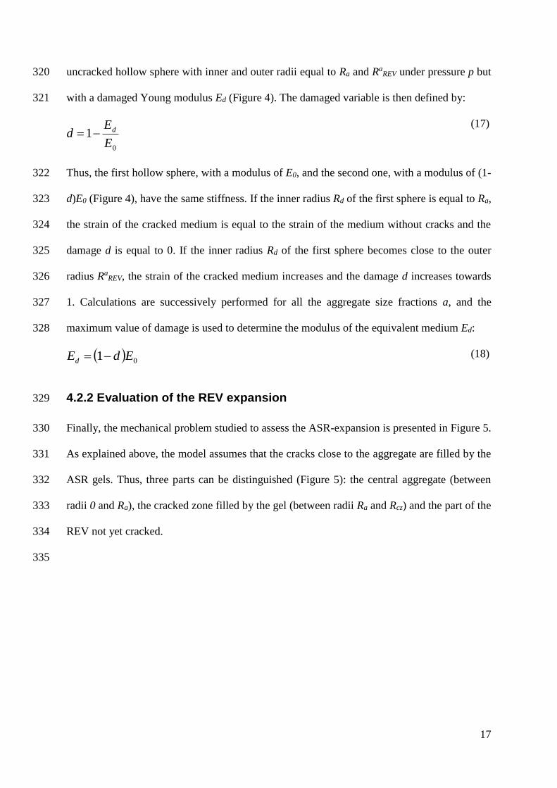
Therefore, as the cracked zone cannot withstand radial tension exceeding the tensile strength, 316
the residual uncracked surrounding concrete is equivalent to a hollow sphere with inner and 317
outer radii equal to Rd and RaREV under pressure p. According to the strain equivalence 318
principle, the radial strain of this hollow sphere must be equal to the radial strain of the 319
Ra
REV
REV modulus E0
Rd
REV modulus Ed = (1-d).E0
REV p
p p
p
RaREV Ra
REV
17
uncracked hollow sphere with inner and outer radii equal to Ra and RaREV under pressure p but 320
with a damaged Young modulus Ed (Figure 4). The damaged variable is then defined by: 321
0
1E
Ed d
(17)
Thus, the first hollow sphere, with a modulus of E0, and the second one, with a modulus of (1-322
d)E0 (Figure 4), have the same stiffness. If the inner radius Rd of the first sphere is equal to Ra, 323
the strain of the cracked medium is equal to the strain of the medium without cracks and the 324
damage d is equal to 0. If the inner radius Rd of the first sphere becomes close to the outer 325
radius RaREV, the strain of the cracked medium increases and the damage d increases towards 326
1. Calculations are successively performed for all the aggregate size fractions a, and the 327
maximum value of damage is used to determine the modulus of the equivalent medium Ed: 328
01 EdEd (18)
4.2.2 Evaluation of the REV expansion 329
Finally, the mechanical problem studied to assess the ASR-expansion is presented in Figure 5. 330
As explained above, the model assumes that the cracks close to the aggregate are filled by the 331
ASR gels. Thus, three parts can be distinguished (Figure 5): the central aggregate (between 332
radii 0 and Ra), the cracked zone filled by the gel (between radii Ra and Rcz) and the part of the 333
REV not yet cracked. 334
335

18
Figure 5 – Mechanical equilibrium of the damaged REV
336
As the gel reaches the cracks connected to the reactive aggregate, the radius Rcz corresponds 337
to the radius Rd used to determine the damage (Figure 4). The gel pressure is constant in both 338
the aggregate and the cracked zone; it is then applied to the internal boundary of the 339
surrounding uncracked concrete. The modulus of the whole medium surrounding the 340
aggregate is equal to Ed according to the damaged Young’s modulus evaluated just above. 341
The following behavior equation, concerning the part of the REV surrounding the aggregate 342
and filled by the ASR gel, had to be added: 343
- the constitutive law: 344
timp
µµItr czczczczczfgcz 2.23..2. (19)
where 345
imp2 is the imposed strain applied to the cracked zone of the surrounding concrete due to 346
presence of ASR gel in the cracks; 347
the displacement is 348
r
cz
czcz er
BrAru ..
2
(20)
Agg
.
r
Rcz
RaREV
+
REV modulus Ed
Aggregate modulus Ea
pg
REV modulus Ed
Agg
.
r
REV modulus Ed
Aggregate modulus Ea
pg
r
Rcz
Rcz Ra Ra
RaREV

19
The two supplementary unknown constants Acz and Bcz can be determined from two 349
supplementary boundary conditions: the continuity of radial displacements and radial stresses 350
at the boundary between the cracked zone and the surrounding concrete. The mechanical 351
equations can thus be solved in function of Rcz, imp1 and imp2. Three last equations are needed 352
to assess the three unknown values of Rcz, imp1 and imp2. The tensile stress is equal to the 353
concrete tensile strength ft for the radius Rcz: 354
tcz
SC fR (21)
The effect of the imposed deformations imp1 and imp2 in the aggregate and in the concrete 355
filled by the gel can be compared to a pressure pg in both the aggregate and the cracked zone 356
(Figure 5). As the pressure pg is an isotropic stress, in the cracked zone filled by the gel 357
cz
cz
cz
cz
rr RR (22)
The imposed strains applied to the aggregate and to the cracked zone are the relative increase 358
in the volume due to the production of gel by ASR. However, as explained above, a part of 359
the gel fills the porous volume surrounding the aggregate (determined by equation 3) and does 360
not participate in the expansion. The imposed strain is then equal to the volume of gel Vg 361
minus the connected porosity Vpor filled by the gel compared to the volume of the aggregate. 362
Thus, the last equation is given by chemical modeling: 363
2
33
1
3
3
4
3
4impaczimpaporg RRRVV
(23)
where
X is equal to X if X > 0 or equal to 0 if X ≤ 0. 364
The damage to the concrete is obtained by substituting the volume of gel determined by the 365
chemical modeling (Eq. 3) in Eq 23. The expansion induced by ASR in each aggregate size 366
fraction can thus be calculated. For the aggregate size fraction a: 367

20
a
REV
a
REVrr
aR
Ru
(24)
with RaREV the radius of the REV corresponding to the aggregate size fraction i. 368
If the concrete contains several aggregate size fractions, the resulting strain is assumed to be 369
the sum of expansions induced by each fraction: 370
a
aASR (25)
The relationship between the damage and the expansion of one reactive aggregate obtained by 371
this model has been plotted in Figure 6. It is interesting to compare these values to 372
experimental data but only a few papers deal with the decrease of direct tensile strength with 373
ASR expansion, and none with the decrease of the tensile modulus. Siemes and Visser 374
measured a decrease greater than 85% in the direct tensile strength for expansions between 375
0.05% and 0.1% [37]. For the same ASR expansions (between 0.05 and 0.1%), the damage 376
calculated by the model is between 60 and 75%, which is slightly lower than the experimental 377
values. 378
0.00
0.05
0.10
0.15
0.20
0.25
0.30
0.35
0.40
0.00 0.20 0.40 0.60 0.80 1.00
d
% s
train
Figure 6 – Relationship between the damage (d) and the expansion of the REV
379
The mechanical modeling uses only five parameters: the Young’s modulus and the Poisson’s 380
coefficient of the aggregate and mortar (Ea,a and Em,m) and the tensile strength of the 381
mortar ft; no other fitting is necessary. 382

21
5. Comparison with experiments 383
The last part of the paper shows some calculations performed with the model developed in the 384
previous parts. In order to assess the capability of the model to represent and predict real ASR 385
expansions, the analysis is divided into three parts. First, experiments used to fit and test the 386
model are presented. Then, the identification of the parameters is carried out and discussed. 387
For the identification, the measurements of expansion performed on four different mortars 388
were used. Finally, the model is used to calculate the expansion of six other mortars. The 389
calculated expansions are compared to the measured ones and the differences are discussed. 390
5.1 Experiments 391
The experiments used to check the capability of the model to predict ASR expansion have 392
been presented and analyzed in a previous paper [38]. Therefore, only the parameters used by 393
the model are dealt with here. Expansion was measured on mortar prisms with a water-cement 394
ratio of 0.5. The sand and cement contents were 1613.4 kg/m3 and 537.8 kg/m3 respectively. 395
Two distinct Na/Si ratios were studied by adjusting the alkali contents (Na2Oeq) to 6.2 and 396
13.4 kg of alkali per m3 of mortar (addition of NaOH in the mixing water). Three size 397
fractions of aggregate were used: FS for small aggregates (80–160 μm), FM for medium 398
aggregates (315–630 μm) and FL for large ones (1.25–3.15 mm). The reactive aggregate was 399
a siliceous limestone. In the experimental study, only fractions FS and FL were composed of 400
reactive aggregates, the medium size aggregates were not reactive but were introduced into 401
the formulation to obtain an acceptable particle size distribution. The reactive silica contents 402
of the two reactive fractions were measured through a chemical analysis based on basic attack 403
[38]; the reactive SiO2 contents were equal to 9.4% and 12.4% per kg of aggregate for FS and 404
FL. The particle size distribution was the same for all the mortars: 30% of FS, 40% of FM and 405
30% of FL. Different proportions of reactive and non-reactive aggregates from the two size 406

22
fractions FS and FL were used to make 5 reactive mortars for each alkali content, with always 407
30% of reactive particles (Figure 7). 408
Figure 7 – Particle size distribution of the five mortars (in black: reactive aggregate, in white:
non-reactive aggregate)
409
The mortar MS0-L100 contained 0% of reactive particles in the SL fraction while 100% of the 410
particles of the FL fraction were reactive. For the mortar MS100-L0, 100% of the smallest 411
reactive particles (FS) were reactive and all the other particles were non-reactive. The reactive 412
particle contents of the mortars MS17-L83, MS50-L50 and MS83-L17, lay between these two values. 413
The ASR expansions presented in Figures 8 and 9, and used for the identification of the 414
parameters and for the analysis of the model were obtained by subtracting the expansion of 415
the reference mortar (without reactive aggregate) from the total expansion [38]. Thus, the 416
strains were only caused by the pressure of the ASR gel and not by the pressure due to water 417
absorption. The water porosity of each of the mortars was measured at the end of the 418
experiment (Table 1), using AFPC-AFREM method [39]. Values were between 17 and 20%. 419
Table 1 – Porosity of the mortars in %
Alkali content of the mix design MS0-L100 MS17-L83 MS50-L50 MS83-L17 MS100-L0
6.2 kg / m3 17.5 16.9 17.3 17.6 17.6
13.4 kg / m3 20 19.9 19.6 18.9 17.9
0
10
20
30
40
50
60
70
80
90
100
MS0-L100
Reactive
Non Reactive Weight fraction of aggregate (%) .
Mortar mixtures
FL
(1250-3150 µm)
FM
(315-630 µm)
FS
(80-160 µm)
MS17-L83 MS50-L50 MS83-L17 MS100-L0

23
5.2 Assessment of the parameters 420
Table 2 sums up the various parameters of the two models, with the symbols, the method used 421
for identification, the values and the units. The following parts explain how the values were 422
obtained. 423
Table 2 – Parameter identification
Parameter Symbol Identification Value Units
Physicochemical modeling
Aggregate
Coefficient of diffusion D curve fitting 3.5 x 10⁻¹³ m²/s
Porosity p usual value 0.01 %
Paste
Porosity of mortar pmort measurement 17.-20. %
Thickness of the connected
porous interface zone
tc curve fitting 0.63 x 10⁻⁶ m
Gel
Molar volume of ASR gel Vgelmol curve fitting 18.2 x 10⁻⁶ m3/mol
Alkali threshold Nath curve fitting 620. mol/m3
alkali fixation coefficient f curve fitting - 6.5 x 10⁻⁷ m3/m3/s
Mechanical modeling
Aggregate
Young’s modulus Ea usual value 70000. MPa
Poisson’s coefficient a usual value 0.2 -
Mortar
Young’s modulus EREV usual value 9000. MPa
Poisson’s coefficient REV usual value 0.2 -
Tensile strength ft usual value 3. MPa
424
5.2.1 Parameters of the physicochemical modeling 425
The first parameters needed for the physicochemical modeling are given by the mix-design 426
information (see above: size and volume fractions of particles, alkali and reactive silica 427
contents). Taking all the information into account, the aggregate concentration per m3 of 428
concrete Cagg could be calculated: it was equal to 0.61. 429
The porosity of the aggregate was taken as the value of 0.01% given by a previous work [40]. 430
The porosity of the cement paste was calculated with equation 7. The last five parameters 431
(coefficient of diffusion, thickness of the connected porous interface zone, molar volume of 432

24
ASR gel, threshold concentration Nath and alkali fixation coefficient) of the physicochemical 433
modeling were obtained by curve fitting on four mortars of the experimental study as 434
explained in 5.2.3. 435
5.2.2 Parameters of the mechanical modeling 436
All the parameters of the mechanical modeling (Table 2) were obtained from the literature. 437
The Young’s modulus of the siliceous limestone was determined in a previous experiment 438
[41]. The instantaneous Young’s modulus of the mortar was taken as equal to a frequently 439
found value for a mortar with a ratio W/C of 0.5: about 27000 MPa. As explained in the 440
presentation of the assumptions, a long-term Young’s modulus equal to one third of the 441
instantaneous Young’s modulus was used in the calculations in order to take the creep effect 442
into account. The Poisson’s coefficients of aggregate and mortar were taken as 0.2. The 443
tensile strength of the mortar was estimated at 3 MPa. None of the parameters of the 444
mechanical modeling were fitted. 445
5.2.3 Identification by curve fitting 446
The five parameters (coefficient of diffusion, thickness of the connected porous interface 447
zone, molar volume of ASR gel, threshold concentration Nath and alkali fixation coefficient) 448
were obtained by curve fitting the expansions of four mortars of the experimental study: the 449
last expansion measured on MS0-L100 with 6.2 kg/m3 of alkali and M2, MS100-L0 with 450
13.4 kg/m3 of alkali, and the whole expansion curves of MS50-L50 with 6.2 kg/m3 of alkali and 451
MS17-L83 with 13.4 kg/m3 of alkali (Figure 8). First, the molar volume of ASR gel and the 452
thickness of the connected porous zone were determined to fit the last expansion measured on 453
the mortars MS0-L100 - 6.2 kg/m3, MS17-L83 and MS100-L0 - 13.4 kg/m3 (Figure 8). Then, the 454
coefficients of diffusion and fixation of alkali were calculated to fit the whole kinetics of the 455

25
expansion of the two mortars MS50-L50 - 6.2 kg/m3 and MS17-L83 - 13.4 kg/m3 (Figure 8). The 456
values thus determined are given in Table 2. 457
0.071
0.224
0.024
0.073
0.224
0.025
0.00
0.05
0.10
0.15
0.20
0.25
MS0-L100 - 6.2 MS17-L83 - 13.4 MS100-L0 - 13.4
Mortar
% s
train
exp
model
0
0.05
0.1
0.15
0.2
0.25
0 100 200 300 400 500
Time (day)
AS
R e
xp
an
sio
n (
%)
MS17-L83_13.4 exp
MS17-L83_13.4 model
MS50-L50_6.2 exp
MS50-L50_6.2 model
Figure 8 – Identification of chemical parameters on mortars MS0-L100-6.2kg/m3, MS50-L50-
6.2kg/m3, MS17-L83-13.4kg/m3 and MS100-L0-13.4kg/m3
458
5.3 Discussion 459
5.3.1 Curve fitting 460
As shown in Figure 8, the determination of the five parameters of the physicochemical 461
modeling allowed a good representation of ASR expansions to be obtained for two different 462
reactive particle sizes and two different alkali contents. As already observed in the analysis of 463
the experiment [38], the larger the aggregate, the higher the ASR-expansion. The model 464

26
explains the decrease of the expansion with the increase in the reactive particle sizes by the 465
movement of a part of the gel into the connected porous zone. The decrease of 90% observed 466
between the small fraction FS and the large fraction FL can be obtained by a thickness of the 467
connected porous zone of about 0.6 µm. The second main parameter of the final expansions 468
of the mortars in the model is the molar volume of ASR gels. The molar volume determined 469
by curve fitting for this experiment, 18.2.10-6 m3/mol, is in good agreement with the 470
experimental values obtained on synthetic gels. In [42], the molar volume of synthetic gels 471
similar to natural ASR gels in solution was measured to be between 17.35.10-6 and 23.65.10-6 472
m3/mol depending on the composition of the gels. The two last parameters have large effects 473
on the kinetics and on the expansion of mortar with low alkali content. Good representation of 474
the expansion curves was obtained with the values given in Table 2. 475
The threshold of alkali above which the ASR-expansion occurred was assessed by curve 476
fitting. With this threshold and all the parameters given in Table 2, for a mortar with a mean 477
porosity of 18%, ASR expansion occurs for alkali content higher than 4 kg of alkali /m3 of 478
concrete. This is in good agreement with the usual values given by the literature (3 and 479
5 kg/m3) [23-26]. 480
5.3.2 Prediction of other expansions 481
Once the curve fitting had been performed, all the other expansions were calculated without 482
any additional fitting (Figure 9). 483

27
0.00
0.02
0.04
0.06
0.08
0.10
0 100 200 300 400 500
Time (day)
AS
R e
xp
an
sio
n (
%)
S0-L100 S17-L83 S83-L17 S100-L0
S0-L100 S17-L83 S87-L17 S100-L0
Na2Oeq = 6.2 kg/m3
exp
mod
0
0.05
0.1
0.15
0.2
0.25
0.3
0 50 100 150
Time (day)
AS
R e
xp
an
sio
n (
%)
S0-L100 S50-L50 S83-L17 S100-L0
S0-L100 S50-L50 S83-L17 S100-L0
Na2Oeq = 13.4 kg/m3
exp
mod
Figure 9 – Prediction of the ASR-expansion of the mortars MS0-L100,
MS17-L83, MS83-L17, MS100-L0-6.2kg/m3 and MS0-L100, MS50-L50, MS83-L17,
MS100-L0-13.4kg/m3
484
For the low alkali content, the kinetics appears to be overestimated but the final expansions 485
are well predicted. For the high alkali content, the mortars MS50-L50 and MS83-L17 are quite 486
well-estimated but the prediction of the mortar MS0-L100 is not good. The differences between 487
the calculations and the measurements of the mortar MS50-L50 can be explained by the 488
sensitivity of the model to the porosity of the cement paste. If the same porosity is taken for 489
the mortar MS100-L0 used in the curve fitting and for the mortar MS50-L50, the prediction is 490
perfect for the two mortars. A variation of 1.5% of porosity (it is the difference between the 491
two mortars of the high alkali content MS50-L50 and MS100-L0) gives a variation of about 0.03% 492
in the calculated expansions. The scatter (the porosity of MS0-L100 lies between 19.5% and 493
20.7%) and the high value of porosity (about 20% for MS0-L100, MS17-L83 and MS50-L50 with the 494

28
high alkali content) can be responsible for the difficulties experienced in obtaining better 495
agreement for the two mortars MS0-L100 and MS50-L50. The delay observed for the mortar MS100-496
L0 can be partly explained by the discretization of the particle sizes: in the present study only 497
one average size was used for each aggregate size range (S,M or L). A better description of 498
the size distribution of the finest particles could improve the modeling results. 499
5.3.3 Interest and limitations of the model 500
The model presented here is mainly based on a previous model developed by Poyet et al. [18]. 501
Several improvements can be noted. In this new model, some considerations have been 502
modified: 503
- Due to the large difference in the diffusion coefficients of the aggregate and the 504
cement paste, the concentration of alkali in the paste has been considered as 505
homogeneous and is represented by a single variable (no more discretization of the 506
paste around each aggregate like in [18]). The calculated values remain reliable, but 507
the duration of calculation is largely reduced. 508
- In order to predict the difference of expansion, the mechanical part of the model 509
presents in [18] was partly based on a parameter which depends on the size of the 510
aggregates. Thus, it was not an intrinsic parameter of the material. In the new model, 511
all the mechanical parameters are intrinsic, i.e. independent of the aggregate size. The 512
expansions of aggregate of different size can be deduced without supplementary 513
fitting. 514
- The definition of a threshold in alkali concentration allows the expansions of mortars 515
containing different alkali contents to be calculated with a good accuracy. No previous 516
models in the literature were tested on this point. 517
Contrary to the previous model [18], the improved new model presented in this paper allows 518
the prediction of ASR expansions of mortars containing particles of different sizes. 519

29
However, the present model still has some limitations. One of the main difficulties in using 520
the model presented above is the determination of the reactive silica content in the aggregate. 521
A method was proposed in [38] for the siliceous limestone studied here, but improvements are 522
still required, particularly to be used for other types of reactive aggregates. 523
Some papers have shown the replacement of the alkali by calcium in the ASR gels [8-10]. 524
This phenomenon has little effect on the expansion obtained in the laboratory for short 525
periods or for mortars with high alkali content because it appears to occur after long period of 526
exposure. However, it can have important effects on the final expansion in real structures 527
because, once free again, alkali can attack more reactive silica and new expansions are 528
possible [6-7]. Therefore, it will be the next improvement made to the model. 529
Moreover, the model was developed with several assumptions (about the diffusion, the 530
composition of the ASR gel, the mechanical properties of mortar under long-term loading, 531
etc.). Supplementary investigations are needed before it can be applied to real structures. In 532
particular, the effect of temperature on all the physiochemical and mechanical mechanisms 533
needs to be analyzed (expansion measurements of mortars kept at several temperatures are 534
currently in progress). This paper has shown the effect of the aggregate size on the prediction 535
of the concrete expansion. It should be taken into account in the expert assessments of real 536
structures already performed in [6-7]. Thus, it would be important to study the effects of the 537
discretization of the aggregate size distribution on the expansion predicted. 538
539

30
6. Conclusion 540
This paper presents an improved empirical microscopic model of ASR expansions based on 541
previous models. It proposes some improvements to take the fixation of alkali into account 542
and to calculate the ASR expansion by means of a mechanical damage variable. The diffusion 543
and the fixation of the alkali are assessed with the mass balance equation. A threshold alkali 544
concentration, above which the formation of the gel starts, is defined; the speed of alkali 545
fixation is assumed to be proportional to the difference between the alkali concentration in the 546
aggregate and this threshold. The mechanical modeling uses a damage variable in order to 547
determine the ASR expansion due to the volume of gel produced by the reaction and 548
determined by the physicochemical part of the model. No parameter of the mechanical model 549
needs fitting. Previous experimental research has been used to check the capability of the 550
model. Four parameters of the physicochemical modeling were determined by curve fitting 551
the expansion curves of four mortars of this experiment. These model parameters have a 552
physical meaning and have been found to be close to previous measurements reported in the 553
literature. The model can reproduce the decrease of expansion with the size of the aggregate, 554
and the increase of expansion with the alkali content. The model is also able to predict the 555
expansions of six other mortars containing two sizes of aggregate and cast with two alkali 556
contents. These calculations have shown the sensitivity of the model to the mortar porosity. 557
Finally, the academic interest of the model lies in the fact that the significance of every 558
assumed mechanism is explained and quantified. 559
Real structures containing large reactive aggregate (size about 100 mm) are currently being 560
analyzed in the LMDC by using the same assumptions as in this model. In this approach, the 561
largest aggregates are crushed and used to make new mortars with high alkali contents in 562
order to quantify the reactive silica remaining in affected concrete aggregate as rapidly as 563

31
possible [7]. Kinetics parameters are assessed on these mortars and the model is used to 564
predict the expansion of larger aggregates with different alkali contents. Thus, the model 565
could be used to predict the slow expansion of concrete in structures from the fast expansion 566
of mortar observed in the laboratory. 567
7. References 568
[1] P. Léger, P. Cote, R. Tinawi, Finite element analysis of concrete swelling due to Alkali-569
Aggregate Reaction in Dams, Comput. Struct. 60 (1996) 601-611. 570
[2] S. Malla, M. Wieland, Analysis of an arch-gravity dam with a horizontal crack, 571
Comput. Struct. 72 (1999) 267-278. 572
[3] F. Ulm, O. Coussy, L. Kefei, C. Larive, Thermo-chemo-mechanics of ASR expansion 573
in concrete structures, ASCE J. Eng. Mech. 126 (3) (2000) 233–242. 574
[4] K. Li, O. Coussy, Concrete ASR degradation: from material modeling to structure 575
assessment, Conc. Sc. Eng. 4 (2002) 35-46. 576
[5] V. Saouma, L. Perotti, T. Shimpo, Stress Analysis of Concrete Structures Subjected to 577
Alkali-Aggregate Reactions, ACI Struct. J. 104 (5) (2007) 532-541. 578
[6] E. Grimal, Caractérisation des effets du gonflement provoqué par la réaction alcali-579
silice sur le comportement mécanique d'une structure en béton, PhD thesis, Université Paul 580
Sabatier Toulouse, France (2007). 581
[7] A. Sellier, E. Bourdarot, S. Multon, M. Cyr, E. Grimal, Assessment of the residual 582
expansion for expertise of structures affected by AAR, 13th Int. Conf AAR, Trondheim, 583
Norway, (2008). 584
[8] J. Duchesne, M-A. Bérubé, Discussion of the Paper "The effectiveness of 585
supplementary cementing materials in suppressing expansion due to ASR – Part 1, Concrete 586
expansion and portlandite depletion", Cem. Conc. Res. 24 (8) (1994) 1572-1573. 587
[9] B. Lagerblad, J. Trägardh, Slowly reacting aggregates in Sweden – Mechanism and 588
conditions for reactivity in concrete, 9th ICAAR, Concrete Society Publication CS 106, 589
London, Great-Britain (1992) 570-578. 590
[10] W.J. French, Maintenance of mobile alkali concentration in cement paste during alkali-591
aggregate reaction, Enclosure to Proc. 8th ICAAR, Kyoto, Japan (1989). 592
[11] P. Goltermann, Mechanical predictions on concrete deterioration. part 1: Eigenstresses 593
in concrete, ACI Mat. J. 91 (6) (1994) 543–550. 594
32
[12] Z.P. Bazant, G. Zi, C. Meyer, Fracture mechanics of AAR in concretes with waste glass 595
particles of different sizes, ASCE J. Eng. Mech. 126 (3) (2000) 226–232. 596
[13] Y. Furusawa, H. Ohga, T. Uomoto, An analytical study concerning prediction of 597
concrete expansion due to alkali-silica reaction, in Malhotra (ed.), 3rd Int. Conf. on Durability 598
of Concrete, Nice, France (1994) 757–780. SP 145-40. 599
[14] A. Nielsen, F. Gottfredsen, F. Thogersen, 1993, Development of stresses in concrete 600
structures with alkali-silica reactions, Mater. Struct. 26 (1993) 152-158. 601
[15] A. Sellier, J-P. Bournazel, A. Mébarki, Modelling the alkali aggregate reaction within a 602
probabilistic frame-work, 10th ICAAR, Melbourne, Australia, (1996) 694-701. 603
[16] Z.P Bazant, A. Steffens, Mathematical model for kinetics of alkali-silica reaction in 604
concrete, Cem. Conc. Res. 30 (2000) 419–428. 605
[17] A. Suwito, W. Jin, Y. Xi, C. Meyer, A mathematical model for the pessimum effect of 606
ASR in concrete, Conc. Sc. Eng. 4 (2002) 23-34. 607
[18] S. Poyet, A. Sellier, B. Capra, G. Foray, J.-M. Torrenti, H. Cognon, E. Bourdarot, 608
Chemical modelling of Alkali Silica reaction: Influence of the reactive aggregate size 609
distribution, Mater. Struct., 40 (2007) 229–239. 610
[19] L.S. Dent Glasser, N. Kataoka, The chemistry of Alkali-Aggregate Reactions, 5th 611
ICAAR, Cape Town, South Africa (1981) S252/23. 612
[20] S. Chatterji, 1979, The role of Ca(OH)2 in the breakdown of portland cement concrete 613
due to Alkali-Silica Reaction, Cem. Conc. Res. 9 (1979) 185-188. 614
[21] S. Diamond, ASR – Another look at mechanisms, 8th ICAAR, Kyoto, Japan (1989) 83-615
94. 616
[22] T.N. Jones, A new interpretation of alkali-silica reaction and expansion mechanisms in 617
concrete, Chemistry and Industry 18 (1988) 40-44. 618
[23] C.A. Rogers, R.D. Hooton, Reduction in mortar and concrete expansion with reactive 619
aggregates due to alkali leaching, Cement, Concrete and Aggregates 13 (1) (1991) 42–49. 620
[24] D.W. Hobbs, Deleterious alkali–silica reactivity in the laboratory and under field 621
conditions, Mag. Conc. Res. 45 (163) (1993) 103–112. 622
[25] M.D.A. Thomas, B.Q. Blackwell, P.J. Nixon, Estimating the alkali contribution from fly 623
ash to expansion due to alkali-aggregate reaction in concrete, Mag. Conc. Res. 48 (177) 624
(1996) 251–264. 625
[26] M.H. Shehata, M.D.A. Thomas, The effect of fly ash composition on the expansion of 626
concrete due to alkali–silica reaction, Cem. Conc. Res. 30 (7) (2000) 1063–1072. 627
33
[27] S. Diamond, Alkali reactions in concrete – pore solution effects, 6th International 628
Conference on AAR in Concrete, Copenhagen, Denmark (1983) 155-166. 629
[28] P. Rivard, M.A. Bérubé, J-P. Ollivier, G. Ballivy, Decrease of pore solution alkalinity in 630
concrete tested for alkali-silica reaction, Mater. Struc 40 (2007) 909-921. 631
[29] S. Urhan, Alkali Silica and Pozzolanic Reactions in concrete. Part 1 : interpretation of 632
published results and an hypothesis concerning the mechanism, Cem. Conc. Res. 17 (1) 633
(1987) 141-152. 634
[30] N. Thaulow, U-H. Jakobsen, B. Clark, Composition of alkali silica gel and ettringite in 635
concrete railroad ties: SEM-EDX and X-ray diffraction analyses, Cem. Conc. Res. 26 (1996) 636
309-318. 637
[31] H.F.W. Taylor, Cement Chemistry, Academic Press, London, 1990. 638
[32] M. Kawamura, H. Fuwa, Effects of lithium salts on ASR gel composition and expansion 639
of mortars, Cem. Conc. Res. 33 (2003) 919-919. 640
[33] E. Grimal, A. Sellier, Y. Le Pape, E. Bourdarot, Creep shrinkage and anisotropic 641
damage in AAR swelling mechanism, part I: a constitutive model, ACI Mat. J. 105 (3) (2008) 642
227-235. 643
[34] BAEL “Règles techniques de conception et de calcul d'ouvrages et constructions en 644
béton armé suivant la méthode des états limites”, Fascicule 62 of CCTG, French design code, 645
1991, modified in 1999. 646
[35] L.M. Kachanov, Introduction to continuum damage mechanics, Martinus Nijhoff 647
Publishers, 1986. 648
[36] J. Lemaître, J.-L. Chaboche, Mécanique des Matériaux Solides, Dunod (Eds.), Paris, 649
France, 1988. 650
[37] T. Siemes, J. Visser, Low tensile strength in older concrete structures with Alkali-Silica 651
Reaction, 11th ICAAR, Quebec, Canada (2000) 1029-1038. 652
[38] S. Multon, M. Cyr, A. Sellier, N. Leklou, L. Petit, Coupled effects of aggregate size and 653
alkali content on ASR expansion, Cem. Conc. Res., 38 (3) (2008) 350-359. 654
[39] AFPC–AFREM (Association Française Pour la Construction – Association Française de 655
Recherche et Essais sur les Matériaux de construction), Durabilité des bétons. Méthodes 656
recommandées pour la mesure des grandeurs associées à la durabilité. Mesure de la masse 657
volumique apparente et de la porosité accessible à l’eau. Compte-Rendu des Journées 658
Techniques, Toulouse, 11-12 Décembre 1997, pp.121–124. 659
[40] S. Poyet, Etude de la dégradation des ouvrages en béton atteints de la réaction alcali-660
silice: approche expérimentale et modélisation numérique multi-échelle des dégradations dans 661

34
un environnement hydrochemo-mécanique variable, PhD thesis, Université de Marne la 662
Vallée, France (2003). 663
[41] C. Larive, Apports combinés de l’expérimentation et de la modélisation à la 664
compréhension de l’alcali-réaction et de ses effets mécaniques, Laboratoire Central des Ponts 665
et Chaussées (Edt.), Ouvrage d’Art, Rapport OA 28, 1998. 666
[42] A. Perruchot, P. Massard, J. Lombardi, Composition et volume molaire apparent des 667
gels Ca–Si, une approche expérimentale, C. R. Geoscience 335 (2003) 951–958. 668
Acknowledgments 669
The authors are grateful to Electricité De France for supporting this work. 670
671
Notations 672
a sub or superscript relative to the size fraction of the reactive aggregate 673
Cagg volume fraction of all the aggregate per m3 of concrete 674
NaC concentration of alkali 675
CNacp alkali concentration in the cement paste 676
CZ subscript relative to the cracked zone surrounding the reactive aggregate 677
D coefficient of diffusion of alkalis into the aggregate 678
d damaged variable 679
strain matrix for each material 680
a expansion induced by ASR in the aggregate a 681
ASR total expansion of the concrete 682
imp1 imposed strain applied to the aggregate 683
imp2 imposed strain applied to the cracked zone 684
E Young’s modulus 685
Ed damaged Young’s modulus 686
a volume fraction of reactive aggregates with mean radius Ra 687
f coefficient of fixation of alkali 688
ft tensile strength of the mortar 689
I unit matrix 690
MNa2O mass of equivalent alkali per m3 of concrete 691
MmolNa2O molar mass of equivalent alkali (equal to 0.062 kg/mol) 692

35
Poisson’s coefficient of the medium 693
Na number of reactive aggregate a in the final REV 694
Nath alkali threshold above which the attack of reactive silica starts 695
nga number of moles of ASR-gel produced by the aggregate a 696
pagg porosity of the aggregate 697
pcp porosity of the cement paste 698
pmort porosity of the mortar 699
Ra mean radius of the reactive aggregate of size fraction a 700
RaREV REV radius corresponding to the aggregate size fraction a 701
stress matrix for each material 702
S(CNa) depletion term which represents the alkali consumption 703
SC subscript relative to the concrete surrounding the reactive aggregate 704
Sr saturation degree 705
tc thickness of the connected porous volume filled by the gel 706
u displacement 707
Vg total volume of ASR gel produced 708
Vgelmol molar volume of the gel 709
Vpo volume of porosity filled by the gel 710
X equal to X if X > 0 or equal to 0 if X ≤ 0 711
712