chemical component quantity - stanford university · the main objectives of this study are to...
TRANSCRIPT

Proceedings World Geothermal Congress 2015
Melbourne, Australia, 19-25 April 2015
1
Pipeline Failure Analysis of Bending Pipe on the Geothermal Production Well KMJ-X7 in
Kamojang Geothermal Field, Indonesia
Achmad Sri Fadli, M.Achyar Karim,Rahmad Harahap 1; Ahmad Taufik
2
1Pertamina Geothermal Energy Kamojang Field,PO BOX 120, Indonesia
2Metallurgical Department of Bandung Institute of Technology, Jl. Ganesha No.10 Bandung, West Java Indonesia
[email protected], [email protected], [email protected]
Keywords: Finite Element Analysis, Erosion, Metal Loss
ABSTRACT
A leak has been found in a bend on a 10” Sch. 40 surface pipe from production well KMJ – X7 in the Kamojang field, Indonesia.
The pipe has been operated for approximately 2 years. The leak position occurred at about 12 o'clock and 30 cm from the flanged
downstream direction. From the results of field observation, inspection and laboratory tests, and finite element simulations with
FLUENT showed that the cause of the bend pipe leak was erosion mechanisms. From the analysis of the chemical composition,
microstructure and mechanical tests in the laboratory, the bend of pipe material still meets the specification of standard code API
5L Grade B. Therefore, it can be concluded that the failure was not caused by the pipe material and fabrication process. The root
cause of the leak was due to significant amounts of silica sand (SiO2), which flowed out of the well and followed the steam flow
into the pipe bend (internal aspects). From the simulation, it can be predicted that the silica content of the existing pipeline will
have a remaining life of 3.4 years, since the operation was first installed in 2008. The premature leak, in addition to the erosion
problem, was also caused by the contribution and role of CO2 corrosion mechanisms, so that the rate of metal loss becomes very
high at 4.6 mm / year.
1. INTRODUCTION
The pipeline, which has outer diameter (OD) of 10 inches, serves dry steam from KMJ-X7 production well in Cluster 69 and then
joins with the main pipeline (32 inch outer diameter) supplying steam to Pertaminas 60 MWe Power Plant. The pipeline has an
operating pressure 16.7 kg/cm2 (237 Psig) and operating temperature 187 °C. To prevent heat loss, the pipe is wrapped with thermal
insulation made of calcium silicate material, with a thickness of five centimeters, and is protected by aluminum sheets. The pipe
material is made from low carbon steel, which meet API 5L Grade B specifications and have been operating since 2008. In
September 2011, a premature leak was found on a ten-inch pipe elbow. The position of the leak is located at the twelve o'clock
position. Leaks in the elbow pipe occurred outside of reliability estimates, as new pipelines are operated less than five years. Before
the failure analysis of the pipeline, the leak was stopped using a mechanical clamp and resolved; at the time it was producing steam.
To ascertain the cause of premature failure of the pipe elbow, the pipe was cut and failure analysis was conducted to obtain overall
conclusions.
The main objectives of this study are to determine the mechanism of pipeline damage (damage mechanism) and understand
important parameters that play a role in it, determining if the cause of a leak in the pipe elbow (root cause) is related to the
operating fluid, material weaknesses or problems related to the fabrication (welds), and determining the next step so that similar
incidents don’t occur in the future.
The scope of this study is to conduct site visits and visual inspection; conduct a review of the design, operation and inspection of
the pipeline; conduct metallographic studies, mechanical testing and material composition test pipe elbow; perform modelling and
simulation with finite element (FLUENT), determining the root cause of the failure and provide appropriate recommendations so
that similar incidents do not recur.
2. DATA DESIGN AND OPERATION PARAMETERS
Data design and operating parameters of the 10 inch S-bend steam pipe can be seen in the table below.
Figure 1: The figure above is data design and operation parameters
Parameters Value and Unit
Material and Grade (Pipe and Elbow) API 5L Grade B
SMYS 35000 Psi
Maximum Allowable Stress 15000 Psi
Outer Diameter Pipeline and Elbow 10.75 Inch
Operation Pressure 16.7 Kg/cm2 (237 Psi)
Operation Temperature 194 Deg Celcius
Thermal Insulator Calcium Cillicate Five Inch
Nominal Pipe Thickness 9.271 mm (schedule 40)
Year Built Pipe 2009
Fluid Product Dry Steam (superheated)
Upstream Flange A105 N - RTJ Type
Dowstream Flange A105 N - RF Type

Fadli, Karim, Harahap, and Taufik.
2
Figure 2: The figure above is chemical composition of steam
3. FAILURE ANALYSIS METHODOLOGY
Methodology and failure analysis stages of work can be seen in Figure 3. The results of this analysis should be able to answer basic
questions such as: Why did the S-elbow pipe fail/leak, while others do not; why occurred the leak at this location; and what is the
root cause of the failure. These are three basic questions guiding this study.
Figure 3: The figure above is Failure Analysis Methodology
As seen in figure 3, the first step was to observe and inspect visually, including documentation with digital photos, then perform
metallurgical analysis and flow analysis using finite elements. Analysis of metallurgical/metallography was performed to see the
microstructure of a material, which includes pipe welding area. Chemical composition tests were conducted to determine if the
material still met the design specifications for the pipe material API 5L Grade B, while the mechanical tests were performed to see
the mechanical properties of the pipe consisting of tensile strength ( SMYS and SMTS ). The analysis of the corrosion products was
performed using SEM / EDAX. In the absence of significant corrosion products, the use of X -ray diffraction was not required in
this study.
Chemical Component Quantity
EC/MIC/CU 32.76
pH (Temp) 4.40 (25 Deg Celcius)
TDS 7.56
Na+ 1.04
K+ 2.83
Ca+ 0.509
Cl- 0.01
HsS 9.73 MMOL /Kg Condensate
SiO2 2.936
CO2 415.05 MMOL/Kg Condensate
CO2/H2S Ratio 42.68
Temperature 194 Deg Celcius

Fadli, Karim, Harahap, and Taufik.
3
4. SITE OBSERVATION
The results of field observations show that there has been a thinning of the elbow pipe rupture location. To overcome this problem
the engineers in the field have put a mechanical clamp to reduce steam leakage due to the impact upon the production of steam. The
impact is noise exposure, the possibility of losing steam and toxic gas exposure (H2S). This can be seen in the Figure 4.
Figure 4 shows how the S-bend is located between the upstream and directly connected with the forty-five-degree elbow at the
bottom, while Figure 5 shows a hole were the thinning occurred in the HAZ (Heat Affected Zone) and the weld area at the twelve
o'clock position.
Figure 4: The figure above is temporary solution with mechanical clamp
Figure 5: Close-up of the leak rupture
5. RESULTS OF INSPECTION AND LABORATORY TESTING
5.1 Visual Inspection
Visual inspection and documentation was carried out on the sample pipe leak in the location as shown on Figure 6, while further
observations were carefully carried out in the laboratory.
5.2 Test Results of Metallography and Mechanical Testing
The type of microstructure of the material S-bend, metallographic test conducted with sampling techniques is shown below. In
general, the microstructure consists of granules ferite (white color) and perlite (black color), which is very typical for low carbon
steel material.

Fadli, Karim, Harahap, and Taufik.
4
Figure 6: In the figure above we can see the outer surface and the inner surface of the S-bend is leaking at the HAZ and
weld area at the 12 o'clock position. The inner surface looks aside general corrosion is also no indication in the form of trail
erosion groove deformation or worn out 10-15 cm to the right of the weld region downstream direction. Also visible is the
indication of corrosion products of iron oxide, Fe2O3 and Fe3O4 yellow brownish on the inner elbow wall (arrows indicate
the direction of flow direction of steam)
Figure 7. Various types of microstructure as a function of welds.
Fadli, Karim, Harahap, and Taufik.
5
Weld metal consists of ferite widmanstaten and acicular and perlite, the HAZ region ferite looks fine granules and metal visible on
the base ferite coarse grains. Because of the differences in the microstructure of these, differences in mechanical properties were
characterized by different values in the table above. It is seen that the structure of the low value of hardness is the value of 156
kg/mm2 HAZ and weld metal is highest with value of 227 kg/mm2. The metal base is about 165 kg/mm2. From the test results, it
can be expected that the HAZ is a location that is more convenient eroded by erosion. To see SMYS and test UTS and deformation
response of the plastic material, tensile tests were performed and the results can be seen on figure 8.
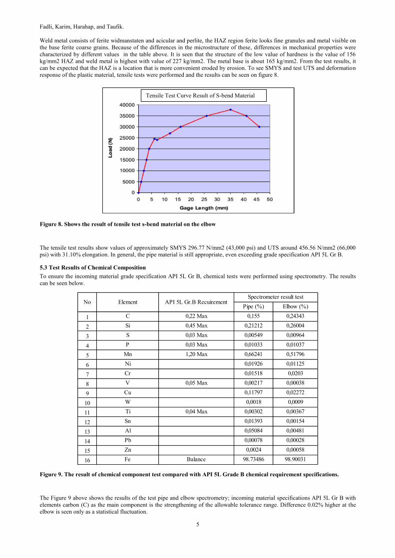
Figure 8. Shows the result of tensile test s-bend material on the elbow
The tensile test results show values of approximately SMYS 296.77 N/mm2 (43,000 psi) and UTS around 456.56 N/mm2 (66,000
psi) with 31.10% elongation. In general, the pipe material is still appropriate, even exceeding grade specification API 5L Gr B.
5.3 Test Results of Chemical Composition
To ensure the incoming material grade specification API 5L Gr B, chemical tests were performed using spectrometry. The results
can be seen below.
Figure 9. The result of chemical component test compared with API 5L Grade B chemical requirement specifications.
The Figure 9 above shows the results of the test pipe and elbow spectrometry; incoming material specifications API 5L Gr B with
elements carbon (C) as the main component is the strengthening of the allowable tolerance range. Difference 0.02% higher at the
elbow is seen only as a statistical fluctuation.
Pipe (%) Elbow (%)
1 C 0,22 Max 0,155 0,24343
2 Si 0,45 Max 0,21212 0,26004
3 S 0,03 Max 0,00549 0,00964
4 P 0,03 Max 0,01033 0,01037
5 Mn 1,20 Max 0,66241 0,51796
6 Ni 0,01926 0,01125
7 Cr 0,01518 0,0203
8 V 0,05 Max 0,00217 0,00038
9 Cu 0,11797 0,02272
10 W 0,0018 0,0009
11 Ti 0,04 Max 0,00302 0,00367
12 Sn 0,01393 0,00154
13 Al 0,05084 0,00481
14 Pb 0,00078 0,00028
15 Zn 0,0024 0,00058
16 Fe Balance 98.73486 98.90031
No Element API 5L Gr.B RecuirementSpectrometer result test
Tensile Test Curve Result of S-bend Material

Fadli, Karim, Harahap, and Taufik.
6
6. FINITE ELEMENT MODELING AND SIMULATION
6.1 Simulation of Flow Patterns in Elbow
The purpose of the modeling and simulation of the flow of steam is to see how far the S-bend geometry influences the vapor flow
pattern, to determine the location of maximum erosion: i) the turbulent kinetic energy, ii) shear stress that occurs as well as iii)
speed erosion. Erosion will occur if there are abrasive particles in the steam flow and if the vapor velocity, V > critical erosion
velocity, Vr (which is a function of fluid densities). From the analysis of the composition of the vapor, silicate sand particles are
SiO2. Steam fluid flow simulation was performed using the FLUENT package. The following data are the input parameters and
assumptions used in simulating the flow of steam.
Figure 10. Fluid Flow Simulation Result using FLUENT
Figure 11.Fluid simulation for corrosion rate calculation in the pipe and elbow
From the results of FLUENT program, the turbulent kinetic energy parameters seem to indicate maximum turbulent energy in the
elbow area (see profile of the turbulent kinetic energy) with a maximum value of 3.50 m2/s2 and 0.842 m2/s2 minimum. This
reflects an increase of 400% of minimum values. Fluent shear stress parameters appear similar to maximum turbulent energy in the
elbow area (see profile shear stress), with a maximum value of 6.31E-04 and 6.31E-05 minimum. This marks a visible increase in
the maximum shear stress, at 10 times the minimum value. Furthermore, the prediction of erosion can be seen in the following
figure. Previous analytical calculations can be performed: speed vapor is 15.95 m/s, while the critical erosion velocity Ve = 16.59 m
Corrosion rate prediction (mm/year)

Fadli, Karim, Harahap, and Taufik.
7
/ s. Because the fluid flow velocity approaches the speed of erosion, erosion is likely to occur in a very big event, especially the
elbow area.
As the results of the program FLUENT predict the erosion rate, it is seen that the maximum value occurs on the elbow area (see
profile erosion prediction), with a value of 1.04 mm / year. Furthermore, to study the effect of the amount of sand on the rate of
erosion, various silicate compositions were re-entered and the erosion rate was re-calculated. From the curve shown below, if the
composition of the silicate sand > 1%, erosion will occur. This is because the fluid velocity > critical erosion velocity.
Figure 12. Predicted erosion rate as a function of the silica sand (SiO2) composition.
From the analysis of FLUENT, it can be seen that there has been erosion of the S-bend pipe wall, due to erosion of fluid flow as the
fluid flow velocity approaches the speed of erosion. This is also supported by the high shear stress values, especially in the elbow
area (4 times greater than the minimum value of shear stress). Additionally, the FLUENT analysis obtained a rate of erosion in
elbow area of 1.04 mm / year. This value is very high and will lead to the rapid depletion in a relatively short time, resulting in a
leak in the elbow area. Detailed finite element analysis and calculation of fluid velocity and erosion can be seen in part-7.
7. REMAINING LIFE, MAWP AND RUPTURE TIME PREDICTION CALCULATION
Based on calculations using the program fluent, a maximum erosion rate of 1.04 mm / year was obtained, along with predicted
erosion rates of an average high 0.9375 mm / year. By using the input data grade pipe (API 5L Gr.B), pipe diameter and thickness
of 10 inches and a maximum of 15,000 psi stress allowable, the next step is to calculate the thickness of the pipe lost per year. The
results of these calculations can be summarized in the table below.
by using the formula
(1)
MAWP can be calculated and the results of these calculations are shown in the figure 13.
Figure 13. MAWP calculation
Fadli, Karim, Harahap, and Taufik.
8
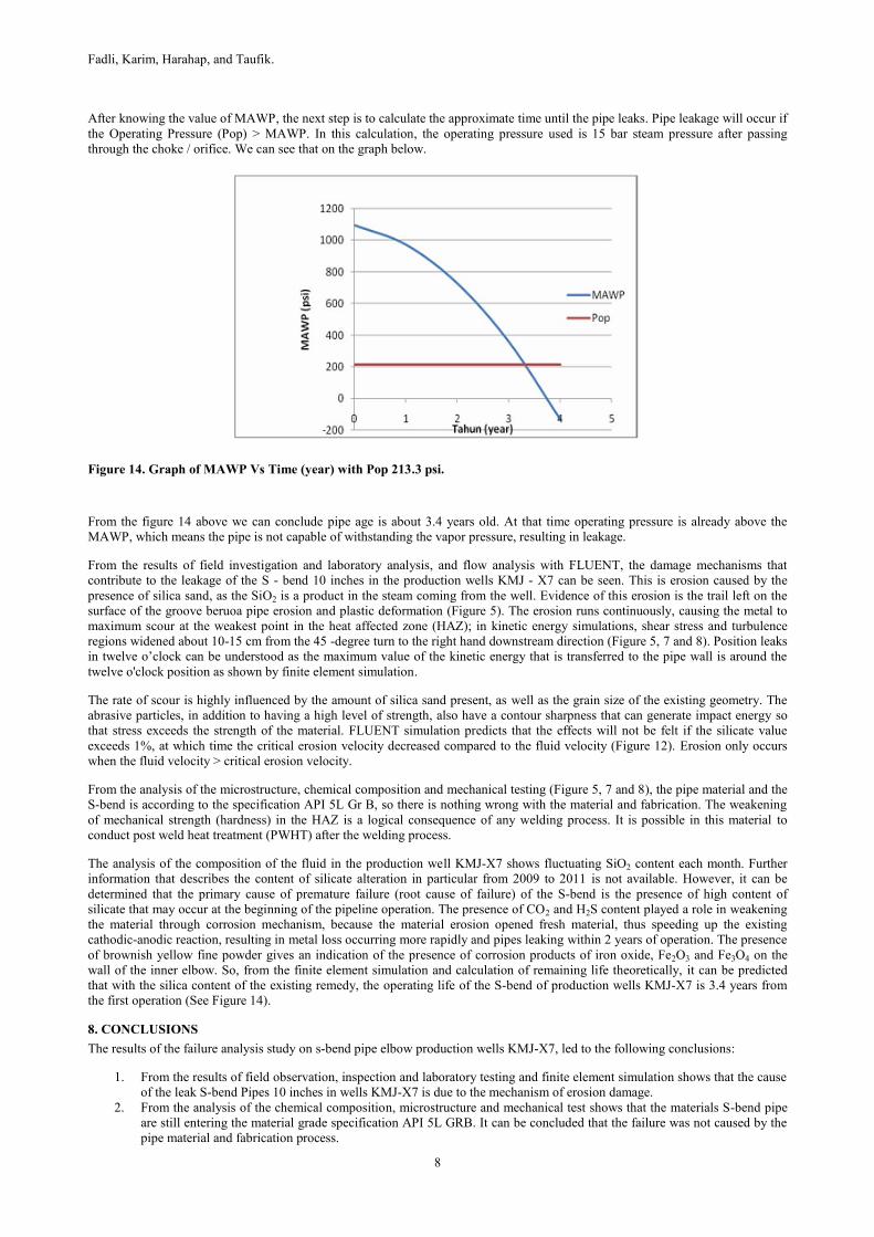
After knowing the value of MAWP, the next step is to calculate the approximate time until the pipe leaks. Pipe leakage will occur if
the Operating Pressure (Pop) > MAWP. In this calculation, the operating pressure used is 15 bar steam pressure after passing
through the choke / orifice. We can see that on the graph below.
Figure 14. Graph of MAWP Vs Time (year) with Pop 213.3 psi.
From the figure 14 above we can conclude pipe age is about 3.4 years old. At that time operating pressure is already above the
MAWP, which means the pipe is not capable of withstanding the vapor pressure, resulting in leakage.
From the results of field investigation and laboratory analysis, and flow analysis with FLUENT, the damage mechanisms that
contribute to the leakage of the S - bend 10 inches in the production wells KMJ - X7 can be seen. This is erosion caused by the
presence of silica sand, as the SiO2 is a product in the steam coming from the well. Evidence of this erosion is the trail left on the
surface of the groove beruoa pipe erosion and plastic deformation (Figure 5). The erosion runs continuously, causing the metal to
maximum scour at the weakest point in the heat affected zone (HAZ); in kinetic energy simulations, shear stress and turbulence
regions widened about 10-15 cm from the 45 -degree turn to the right hand downstream direction (Figure 5, 7 and 8). Position leaks
in twelve o’clock can be understood as the maximum value of the kinetic energy that is transferred to the pipe wall is around the
twelve o'clock position as shown by finite element simulation.
The rate of scour is highly influenced by the amount of silica sand present, as well as the grain size of the existing geometry. The
abrasive particles, in addition to having a high level of strength, also have a contour sharpness that can generate impact energy so
that stress exceeds the strength of the material. FLUENT simulation predicts that the effects will not be felt if the silicate value
exceeds 1%, at which time the critical erosion velocity decreased compared to the fluid velocity (Figure 12). Erosion only occurs
when the fluid velocity > critical erosion velocity.
From the analysis of the microstructure, chemical composition and mechanical testing (Figure 5, 7 and 8), the pipe material and the
S-bend is according to the specification API 5L Gr B, so there is nothing wrong with the material and fabrication. The weakening
of mechanical strength (hardness) in the HAZ is a logical consequence of any welding process. It is possible in this material to
conduct post weld heat treatment (PWHT) after the welding process.
The analysis of the composition of the fluid in the production well KMJ-X7 shows fluctuating SiO2 content each month. Further
information that describes the content of silicate alteration in particular from 2009 to 2011 is not available. However, it can be
determined that the primary cause of premature failure (root cause of failure) of the S-bend is the presence of high content of
silicate that may occur at the beginning of the pipeline operation. The presence of CO2 and H2S content played a role in weakening
the material through corrosion mechanism, because the material erosion opened fresh material, thus speeding up the existing
cathodic-anodic reaction, resulting in metal loss occurring more rapidly and pipes leaking within 2 years of operation. The presence
of brownish yellow fine powder gives an indication of the presence of corrosion products of iron oxide, Fe2O3 and Fe3O4 on the
wall of the inner elbow. So, from the finite element simulation and calculation of remaining life theoretically, it can be predicted
that with the silica content of the existing remedy, the operating life of the S-bend of production wells KMJ-X7 is 3.4 years from
the first operation (See Figure 14).
8. CONCLUSIONS
The results of the failure analysis study on s-bend pipe elbow production wells KMJ-X7, led to the following conclusions:
1. From the results of field observation, inspection and laboratory testing and finite element simulation shows that the cause
of the leak S-bend Pipes 10 inches in wells KMJ-X7 is due to the mechanism of erosion damage.
2. From the analysis of the chemical composition, microstructure and mechanical test shows that the materials S-bend pipe
are still entering the material grade specification API 5L GRB. It can be concluded that the failure was not caused by the
pipe material and fabrication process.

Fadli, Karim, Harahap, and Taufik.
9
3. Root cause of the cause of the leak is that it contains silica sand SiO2 (natural causes) is quite significant that out of the
production wells and the flow follows the steam out and towards the S-bend for the last 4 years (see Data fluid 2008 s / d
2011). The condition causes a depletion rate of 4.6 mm elbow / year for 2 years of operation.
4. Orifice diameter on the X-Tree does not affect the rate of erosion, of calculation fluent no significant difference in flow,
after choking, between the S-bend one well to the other wells.
5. The premature leakage, in addition to erosion, likely caused by the presence of contribution and role of CO2 corrosion
mechanism so that the rate of metal loss became very high.
REFERENCES
Metals Handbook 9th Edition, Volume 11. Failure Analysis and Prevention, Section Failure of Pipeline (1986).
ASME B31.1 Piping for Power Plant, American Society for Mechanical Engineer (2009)
API 5L, Line Pipe, American Petroleum Institute. (2010)
API RP 14E, Recommended Practice for Design and Installation of Offshore Production Platform Piping Systems (1991)
Yong Bai & Qiang Bai, : Subsea Engineering Handbook, Chapter 18 Erosion and Sand Management, Elsevier (2010)
Charlie Brooks and Ashok Choudhury, : Metallurgical Failure Analysis, McGraw‐Hill (1993).