chauvin arnoux uk vs - esi.info · and notably the nf en 50160:voltage changes (dips,swells and...
TRANSCRIPT

ElectricalNetworkAnalyzers
TEST THE QUALITY
OF YOUR ELECTRICAL
INSTALLATIONS

Presen
tatio
nNe
twork
Analy
zers
ENERDIS, A GLOBAL SOLUTION FORMONITORING NETWORKS, STATIONS,AND HVA / HTB INSTALLATIONS
ENERDIS, renowned specialist in metering, monitoring,and management of electrical networks, is extending its product and service offer to energy quality and disturbance measurement for stations, networks and in HVA / HVB installations:
Do you worry because your process is particularly sensitive to supply voltage fluctuations and to generated or received disturbances?
Do you fear that if your equipment malfunctions or shuts down, you could experience serious operating losses or your installations could become less safe?
Do you wish to discuss the quality of your energy supply with the network supplier or manager using factual data as a basis?
The new range of MAP network analyzers launched by Enerdis enable you to measure the magnitude of disturbances very precisely and help you diagnose theorigin and the causes. Its associated software increases MAP's performance and reliability by enabling you to get to the heart of the problem, understand andremedy it.
Through its product offer and along with its expertiseand services adapted to your needs, ENERDIS is engagedin controlling the quality of your electrical energy.

1
CONTENTS
Selection Guide MAP and NRGCENTER Ranges p.2 Info & Advice Column “Keeping up with current events…” p.4MAP RANGE Voltage Analyzers for MV / LV networks
p.7
MAP 5000
p.7
MAP 5100
p.7
MAP 6000
p.10
Operating SoftwareNRGCENTER
p.7
MAP 5200
p.15
Operating SoftwareWIN ID16
p.17
Operating SoftwareWIN ASM8
ID16M RANGE Voltage Analyzers for MV / LV networks
ASM8 RANGE Current Load Curve Analyzer
p.15
ID16M
p.17
ASM8
p.17
ASM8/H61

Selec
tion
Guide
Network
Analy
zers CHOOSING A NETWORK ANALYZER
MAP RANGE MAP 5000 MAP 5100 MAP 5200 MAP 6000
In standard Optional
• Fault recordings• En50160• IEC 61 000-4-30
• 144*144 format• Metering• Harmonic
measurements
• Transient analysis• Memory• E/S
• Disturbance analysis• Multiple communication• Sampling frequency
MAP 5000 MAP 5100 MAP 5200 MAP 6000Installation
Rack 19'' double unity simple unity simple unity
Format1/2 Rack 19" simple unitySlot-in 144x144Plate Mounting 144x144
Voltage inputs (4 U inputs) 100 Vac, 400 Vac 100 Vac, 400 Vac 100 Vac, 400 Vac 55 to 400 or 600 VacCurrent Direct on internal shunt 1, 5 or 10 A 1, 5 or 10 A 1, 5, 10 or 20 Ainputs Direct on external shunt 1, 5 or 10 A(4 I inputs) On clamps 0 to 2 V 0 to 2 V 0 to 2 V 0 to 2 V
SamplingSampling frequency 12.8 kHz 12.8 kHz 12.8 kHz 37.5 kHzFrequency for rapid transients 1 MHz 1 MHz
MemorySDRAM 16 Mbytes 16 Mbytes 16 Mbytes 16 Mbytes
8 Mbytes 8 Mbytes 8 Mbytes 8 MbytesFlash +8 Mbytes, +16Mbytes, +8 Mbytes, +16Mbytes, +8 Mbytes, +16 Mbytes, +8 Mbytes, +16 Mbytes,
+24 Mbytes +24 Mbytes +24 Mbytes,+56 Mbytes +24 Mbytes,+56 Mbytes
Input(s) / Output(s)
Logic inputs 2 4 88 8
+8 +8
Binary outputs44 44 4
+4 +4Analogue inputs 4 4 4Analogue outputs 4 4, 8 or 16 4, 8 or 16
CommunicationRS485 port COM 1 COM 2 COM 2 COM 2Ethernet port 1 1 1 1Optical infrared port
via RS232 COM 1 via RS232 COM 1 via RS232 COM 1via RS232 COM 1
External modem (GSM or RTC) V34 bis via RS232 COM 3Internal Modem COM 2 COM 1 COM 4USB Port 1 1 1 1Optical fiber (ST2) 1 1 1 1
Internal clockExternal synchronizationGPS synchronizationDCF synchronization
Auxiliary power supplyUPS 30 min 1 1 1 1
Accuracy
RMS measurements0.2 % 0.2 %
0.1 % 0.1 %0.1 % 0.1 %
Energy (EN 60 687) 0.5 S 0.2 S 0.2 S 0.2 SInternal clock 15 ppm 15 ppm 15 ppm 15 ppm
Strong points

23
NRGCENTERNRG CENTER OPTION 1 OPTION 2 OPTION 3 OPTION 4Configuration Advanced analysis Metering Management Configuration & monitoring tool kit
Multi-measureVoltage and current, per phase and globalFrequencyTHD-U and THD-IEnergies: max / min / avgP, Q, SPower FactorCos phiVoltage and current, vectorial representationK FactorVoltage qualimetryRapid changesSlow changesVoltage dipLong interruptions / Short interruptionsLong-term flicker (120mn) / Short-term flicker (10mn)Frequency fluctuationsUnbalanceVoltage harmonics up to the 63rd orderVoltage interharmonicsSymmetric network components Network impedanceGraphic data representation on ITIC curve (CBEMA)Analysis as per standards in effect or defined by userCurrent qualimetryCurrent harmonics up to the 63rd orderCurrent interharmonicsOvercurrentMeteringTariffMetering in the 4 quadrantsSub-meteringTesting and management of solicited power Line/transformer compensation lossRecordingRecording waveformsRecording disturbancesRecording transientsEvent correlationTriggering on thresholds or external signalsRemote control signals (up to 4 frequencies)Generating COMTRADE filesAlarmsProgramming alarm as per a criterion (threshold, duration or hysteresis)Programming alarms as per many criteria (threshold, duration and hysteresis)Automatic sending of alert message via PCDisplaying a pop-up alarm Automatic sending of alert e-mail or SMS via PCAutomatic sending of direct e-mail or SMS (add. card)
ManagementUsing standard reportsCreating customized reportsGraphic interface: standard display screensGraphic interface: customized display screensDisplaying multi-station data transfers and in real timeTask management (rate, continuous)Multi-site network access (via server)Manage user: definition and configurationRemote firmware and configuration updateNT/XP/2000 operating system and safety

Introdu
ction
Network
Analy
zers KEEPING UP WITH CURRENT
For many years now, load modifications, disturbances generated by certainequipment, and externally caused faults have been observed on electrical networks.All these sources of supply voltage degradations are harmful to the operating ofelectrotechnical material and equipment.
What are these disturbances? What are their causes and consequences?
• Supply voltage dips and swells• Mini interruptions < 10 ms • Short < 3 min and long interruptions > 3 min
• Strong loads connected to the network and the power of the short-circuit at a supply point is insufficient.
• High-power motors, transformers and capacitance assemblies• Internal fault in the electrical installation
• Atmospheric phenomena and accidental short-circuit• Transport and distribution network management uncertainties
• Magnitude and duration of the change
Generated faults
Causes linked to disturbing equipment
Causes linked to theelectrical supply network
Parameters to measure
The energy distributor sets the nominal change range of the network voltage at ± 10 % of the line voltage
S L O W C H A N G E S A N D I N T E R R U P T I O N SVoltage magnitude is generally the energy distributor's primary contractual engagement.And yet, abnormal changes can reach a near 0 level.
R A P I D C H A N G E SMeasuring transient swells requires digital analyzers with high sampling frequency.
• Transient swells (<10 ms)
• More or less inductive load commutations that produce high-frequencytransient swells
• Commutation with 2 thyristors that provoking a short-term short-circuit between the 2 phases
• Atmospheric phenomena (lightning)
• Maximum magnitude and duration of the transient
Generated faultsCauses linked to disturbing equipment
Causes linked to theelectrical supply network
Parameters to measure
• Changes in light intensity• Flickering on computer screens• Arc furnaces, laser printers, air conditioning systems
• None
• Short-term (Pst) and long-term flicker (Plt)
Generated faults
Causes linked to disturbing equipment
Causes linked to theelectrical supply network
Parameters to measure
R A P I D F L U C T U A T I O N S I N V O L T A G E ( F L I C K E R )The discomfort felt by the flicker of light intensity is measured by the flicker value.Effects on people: headaches, irritability, epileptic seizure, etc.…

EVENTS…
45
For the electrical energy distributor, it isessential to deliver a quality product, i.e.a voltage at 50 Hz, that is sinusoidal,balanced three-phase, at a nominalvalue. The energy delivered needs to correspond to the user-customer's bill.Many standards have been created tohelp distributors and users take steps to monitor and improve the quality ofelectrical networks.
The EN 50160 standard provides themain characteristics of the quality of the voltage supplied to the customer'spoint of supply by the LV and MV pub-lic distribution network: frequency, wave-form magnitude, and symmetry of thethree-phased voltages during a defined observation period. It defines the limitsor the characteristic values of the voltage that the customer has the rightto expect.
The IEC 61 000-4-30 was elaboratedto measure the different voltage qualityparameters and obtain reliable resultsthat can be reproduced and comparedregardless of the measurement instru-ment used and environmental conditions.This standard defines measurement meth-ods for each parameter and how to interpret the results. It also specifiesprecautions to take in installing measurement instruments on live circuits.
QUIZZTest your knowledge with 3 questions.
THE STANDARDS
You are in a region that has a lot ofstorms; you have powered off the installation,which parameters need to be monitored?
Voltage changesTransient phenomenaFlicker
You have untimely trip-outs, what could be the cause?
SwellsHigh rate of harmonicsUnbalance in your installation
You should test the quality of the supplyin your installation, which standard is mostwidely used?
EN5016061000-4-30ISO 14100
• Synchronization, commutation functionproblems
• Untimely tripping• Armature temperature rise diminishing thelife span of rotating machines, capacitors,power transformers, neutral conductors
• Equipment with powerful electronics:variators, inverters, static converters, lightdimmers, welding units
• Propagation of harmonic pollution fromcustomers supplied by the same electricalnetwork
• Global THD• Harmonics order by order in % and RMSvalue
Generated faults
Causes linked to disturbingequipment
Causes linked to the electricalsupply network
Parameters tomeasure
Harmonic: sinusoidal waves (frequencies inmultiples of 50 Hz) superimposed on thefundamental wave (50 Hz)
Interharmonics: signaling componentsuperimposed on the fundamental wave (50 Hz). It is not a multiple of thisfundamental (ex: 175 Hz)
H A R M O N I C S A N D I N T E R H A R M O N I C SCurrent consumed by the loads no longer has a pure sinusoidal shape.The distortion in current implies a distortion in voltage and also depends on thesource's impedance.
• Current and voltage that is not phase-shifted 120° with different magnitudes
• Load absorbing energy in an unbalancedway on the 3 phases
• Disconnection of a electrical power supplyphase
• Disconnection of a electrical power supplyphase
• Rate of unbalance, direct voltage orcurrent, negative and zero sequence
Generated faults
Causes linked to disturbingequipment
Causes linked to the electricalsupply network
Parameters tomeasure
V O L T A G E U N B A L A N C E
• Process stop
• Control fault from the autonomous source
• Following an overload on networks that isnot interconnected or powered by generator sets
• Frequency F(Hz)
Generated faults
Causes linked to disturbingequipment
Causes linked to the electricalsupply network
Parameters tomeasure
F R E Q U E N C Y C H A N G E SFrequency changes are observed on networks that are not interconnected andnetworks powered by generating sets.
In normal operating conditions, the average value of the frequency should fall within the 50 Hz ± 1 % interval

MAP
Rang
eNe
twork
Analy
zers MAP RANGE
MV / LV Electrical Network Quality Analyzers
Slot-in or rack MAP range products measure all MV / LV electrical network parameters:RMS voltage and current; distorting, apparent, reactive, active power; energies; cos ϕ andpower factor;THD-U and THD-I; harmonics up to the 63rd order and interharmonics;negative sequence unbalance in voltage and current, etc.
Via its NRGCenter software, MAP records and provides a complete, continuous and in-depth analysis of the quality of the supplied electricity according to standards in effect,and notably the NF EN 50160: voltage changes (dips, swells and interruptions), rapidchanges (transient voltages), flicker or rapid voltage fluctuations, etc.
Different communication modes are available to provide remote data recovery for makingin-depth analysis of all recorded parameters.
Digital and analogue inputs and outputs (in standard or as an option) make it possible to:• monitor rotation speed, pressure and transformer temperature measurements• display status (open or closed) of circuit breakers and protection relays• meter energy• test equipment (capacitor batteries, filters, generators, alarm system, etc.)
LCD screen forinspecting goodworking order
8 differential (4U, 4I)measurement inputs
Communicationinterfaces:Ethernet, RS232,RS485 optical link
Description
PRODUCT STRONG POINTS
IN CONFORMITY with EN 61000-4-30 standard class A (Supply quality measurement methods)
Detects and locates faults
Analyzes transients with high and variable sampling frequency
Measures harmonics (up to the 63rd order) and flicker
Processes data as per EN 50160 standard
MAP 5000
MAP 5100
MAP 5200
MAP 6000

p.10
Operating SoftwareNRGCenter
see EnerdisCatalogue
JVS CurrentTransformers
see EnerdisCatalogue
TCRO CurrentTransformers
Associated products
67
24
MAP 5000
MAP5100
MAP 5200
MAP 6000
ModelsSimple unity (1/2 rack 19’’) or double unity (rack 19’’)
Current inputsdirect (1,5 or 10 A) or with clamps
Flash memory8, 16, 24 or 32 Mbytes
Sampling 12.8 kHz
Inputs / outputs4 logic inputs4 logic outputs
CommunicationEthernet Port optional USB Port optionalOptical fiber (ST2) optionalRS485 Port RS232 infrared optical portRS232 port for GSM or RTCexternal modem RTC internal modem
Internal clockGPS receiver optionalDCF receiver optional
Auxiliary supplyInternal battery
AccuracyClass 0.2 or class 0.1
Models144x144 format or plate
Current inputs(1, 5 or 10 A) or with clamps
Flash memory8, 16, 24 or 32 Mo
Sampling 12.8 kHz
Inputs / outputs8 logic inputs4 logic outputs0 or 4 analogue inputs0 or 4 analogue outputs
CommunicationEthernet Port optional USB Port optionalOptical fiber (ST2) optionalRS485 PortRS232 infrared optical portRS232 port for GSM or RTCexterne GSM or RTCexternal modem
Internal clockGPS receiver optionalDCF receiver optional
Auxiliary supplyInternal battery optional
AccuracyClass 0.2 or class 0.1
ModelsRack 19”
Current inputs(1, 5 or 10 A) or with clamps
Flash memory8, 16, 24, 32 or 64 Mbytes
Sampling 12.8 kHzRapid acquisition 1 MHzoptional
Inputs / outputs8 or 16 logic inputs4 or 8 logic outputs 0 or 4 analogue inputs0, 4, 8 or 16 analogue outputs
CommunicationEthernet Port in standard USB Port in standardOptical fiber (ST2) optionalRS485 Port RS232 infrared optical portRS232 port for GSM or RTC external modemRTC internal modem
Internal clockGPS receiver optionalDCF receiver optional
Auxiliary supplyInternal battery
AccuracyClass 0.1
ModelsRack 19”
Current inputsdirect (1,5,10 or 2 0A)or with clamps
Flash memory8, 16, 24, 32 or 64 Mbytes
Sampling 37.5 kHzRapid acquisition 1 MHzoptional
Inputs / outputs8 or 16 logic inputs4 or 8 logic outputs 0 or 4 analogue inputs0, 4, 8 or 16 analogue outputs
CommunicationEthernet Port USB PortOptical fiber (ST2) optionalRS485 Port RS232 infrared optical portRS232 port for GSM or RTC external modemRTC internal modem
Internal clockGPS receiver in standardDCF receiver optional
Auxiliary supplyInternal battery
AccuracyClass 0.1
T O O R D E R
1 A direct5 A direct10 A direct20 A directwith clamps
5000510052006000
OK 04
8 Mbytes16 Mbytes24 Mbytes32 Mbytes64 Mbytes
Model* Current Flash Sampling Logic Logic Analogue Analogue Communication Internal Auxiliary Accuracyinputs memory F = 1 MHz inputs outputs inputs outputs clock supply
04816
OK 0.10.2
4816
48
Customized products
SELECTION GUIDEINFO & ADVICE
MAP 5200 10 A direct 32 Mbytes OK 16 8 4 8 OK 0.1
*For MAP 5000, specify: simple or double unity, MAP 5100: 144x144 format or plate
EthernetPortUSB Port Optical fiberlink (ST2)
GPSReceiver DCFReceiver

MAP
Rang
eNe
twork
Analy
zers
Electrical specificationsVoltage Inputs • 4 independent differential inputs• Measurement range: 100 Vac (Ph-N) / 174 Vac (Ph-Ph)
400 Vac (Ph-N) / 693 Vac (Ph-Ph)• Accuracy class: 0.2 or 0.1• Overload: 2 permanent Un• Galvanic insulation: 2.5 kV• Impedance: 10 kΩ per phase
Current Inputs• 4 independent differential inputs• Direct current inputs:1, 5 or 10 A on internal shunt (MAP 5000 or MAP 5200)1, 5, 10 or 20 A on internal shunt (MAP 6000)1, 5, 10 A on external shunt (MAP 5100)• Current inputs on clamps: 0 to 2 V• Accuracy class: 0.2 or 0.1• Overload: 3 permanent In
20 In for 0.5 sec• Galvanic insulation: 2.5 kV• Impedance: 10 Ω
Logical Inputs • Triggering voltage: 24 to 300 Vdc• Consumption: 3 mA per channel / 70 mW per channel• Insulation: polarity protection
Galvanic insulation with optocouplers• Minimum pulse: 0.1 ms• Scanning frequency: 10 kHz
Logic Outputs (solid-state relays) Outage power: 220 V – 2 A – 60 WInsulation: galvanic insulation, free potential
Analogue Inputs Sampling period: 100 msScale Voltage: ± 10 VScale Current: ± 20 mA (with external shunts)Scale Thermocouple: J, K,T
Analogue Outputs Programmable scale: ± 10 V or 4-20 mAAccuracy: 0.2 %
Digital Output Type: RS 485
Protocol: RTU ModbusType: RS 232
Protocol:Y modem Type: Ethernet
Protocol:TCP/IPType: RTC modem
Speed: up to 115 Kbits
Auxiliary supply 24 to 60 Vdc (± 10%)100 to 240 Vac (± 10%)
Environment
Mechanics
MV / LV electrical network quality analyzers
MAP RANGE
Mass: 4 kg (MAP 5000 and 5100)6kg (MAP 5200 and 6000)
Connection: 4 mm2 for U and I2.5 mm2 for inputs / outputs
Mounting: Slot-in (MAP 5100)Rack (MAP 5000, 5200 and 6000)
Operating temperature: -10 to 55°CStoring temperature: -20 to 70°CRelative humidity: < 90 % without condensationInstallation category: 300 V cat IIIPollution degree: 2Protection level: IP 52 (front panel)
Conformity to StandardsMeasurements• EN 61000-4-30: Voltage quality measurement method
(RMS values Class A)• EN 61000-4-7: General guide on harmonic
and interharmonic measurements• EN 61000-4-15: Test and measurement techniques:
flickermeter• EN 62053-22: Electricity metering equipment
(Class 0.2S or 0.5S)• EN 62053-23: Reactive energy meters
(class 2 and 3)
Safety (Low Voltage Directive) • EN 61010-1: Safety rules concerning electrical
equipment for measurement, testingand laboratory use
• EN 60950: Safety for data processing instruments
Communication:• EN 61107: RTU Modbus optical communication
Electromagnetic compatibility:• EN 61326-1: EMC regulations regarding electrical
equipment for measurement, controland laboratory
Including:• EN 61000-4-2: Electrostatic discharge immunity test
Level 3 (Air 8 kV / Contact 4 kV)• EN 61000-4-3: Radiated, radio-frequency,
electromagnetic field immunity testLevel 3 (10 V/m)
• EN 61000-4-4: Electrical fast transient/burst immunity test Level 4 (2kV)
• EN 61000-4-5: Surge immunity test Level 4 (commonmode 2 kV, differential 1kV)
• EN 61000-4-6: Immunity to conducted disturbances,induced by radio-frequency fields Level 3 (3 Vrms)
• EN 61000-4-8: Power frequency magnetic field immunity test Level 4 (30 A/m)
• EN 61000-4-11: Voltage dips, short interruptions, andvoltage variations immunity tests Level 0(duration 0.5 period – 100 % U)
• EN 61000-4-12: Oscillatory waves immunity test Level 3(common mode 2.5 kV / diff.Mode 1.0 kV)

89
SELECTION GUIDEINFO & ADVICE
RANGE INFO
Dimensions (in mm)
Electrical connections
Mass: 4 kg Mass: 4 kgMounting: slot-in model
Mass: 6 kg
MAP 5000 MAP 5100 MAP 5200 and 6000
246

Analy
sis Soft
wareNe
twork
Analy
zers NRGCENTER SOFTWARE
Data processing and report publishing software for the MAP range
Depending on the options selected, NRGCenter software makes it possible to:• configure MAP,• schedule parameter readings,• display electric parameters (monitoring mode),• read recorded data,• analyze disturbances and transients,• make EN 50160 analysis,• print reports,• send alerts by e-mail, SMS, …
MAP analyzerssimple to configure
Graphic display of all availableparameters
Pre-defined report publishing
Description
PC platformPC operating system:Windows 98, NT, 2000, ME, XPPC processor: Pentium IIFrequency: 400 MHzMemory: 128 Mbyte RAMHard drive space: 70 Mbytes
Minimum configuration
PRODUCT STRONG POINTS
ANALYSIS and DIAGNOSIS according to standards in effect.
FAST DATA ANALYSIS.
EASY TO USE.
NRG Center
p.6
Network Analysers MAP Range
Associated product
1011
24
SELECTION GUIDEINFO & ADVICE
OPTION 1
NRGCENTER
OPTION 2 OPTION 3 OPTION 4
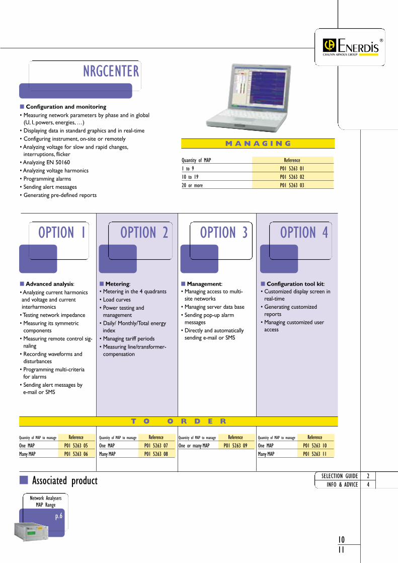
Advanced analysis:• Analyzing current harmonicsand voltage and current interharmonics
• Testing network impedance• Measuring its symmetric
components• Measuring remote control sig-
naling• Recording waveforms and
disturbances• Programming multi-criteria
for alarms• Sending alert messages by
e-mail or SMS
Configuration and monitoring• Measuring network parameters by phase and in global
(U, I, powers, energies, …)• Displaying data in standard graphics and in real-time• Configuring instrument, on-site or remotely• Analyzing voltage for slow and rapid changes,
interruptions, flicker• Analyzing EN 50160• Analyzing voltage harmonics• Programming alarms• Sending alert messages• Generating pre-defined reports
Metering:• Metering in the 4 quadrants• Load curves• Power testing and
management• Daily/ Monthly/Total energy
index• Managing tariff periods• Measuring line/transformer-
compensation
Management:• Managing access to multi-
site networks• Managing server data base• Sending pop-up alarm
messages • Directly and automatically
sending e-mail or SMS
Configuration tool kit:• Customized display screen in
real-time• Generating customized
reports• Managing customized user
access
T O O R D E R
Quantity of MAP to manage ReferenceOne MAP P01 5263 05Many MAP P01 5263 06
M A N A G I N G
Quantity of MAP Reference1 to 9 P01 5263 0110 to 19 P01 5263 0220 or more P01 5263 03
Quantity of MAP to manage ReferenceOne MAP P01 5263 07Many MAP P01 5263 08
Quantity of MAP to manage ReferenceOne or many MAP P01 5263 09
Quantity of MAP to manage ReferenceOne MAP P01 5263 10Many MAP P01 5263 11
Analy
sis Soft
wareNe
twork
Analy
zers NRGCENTER
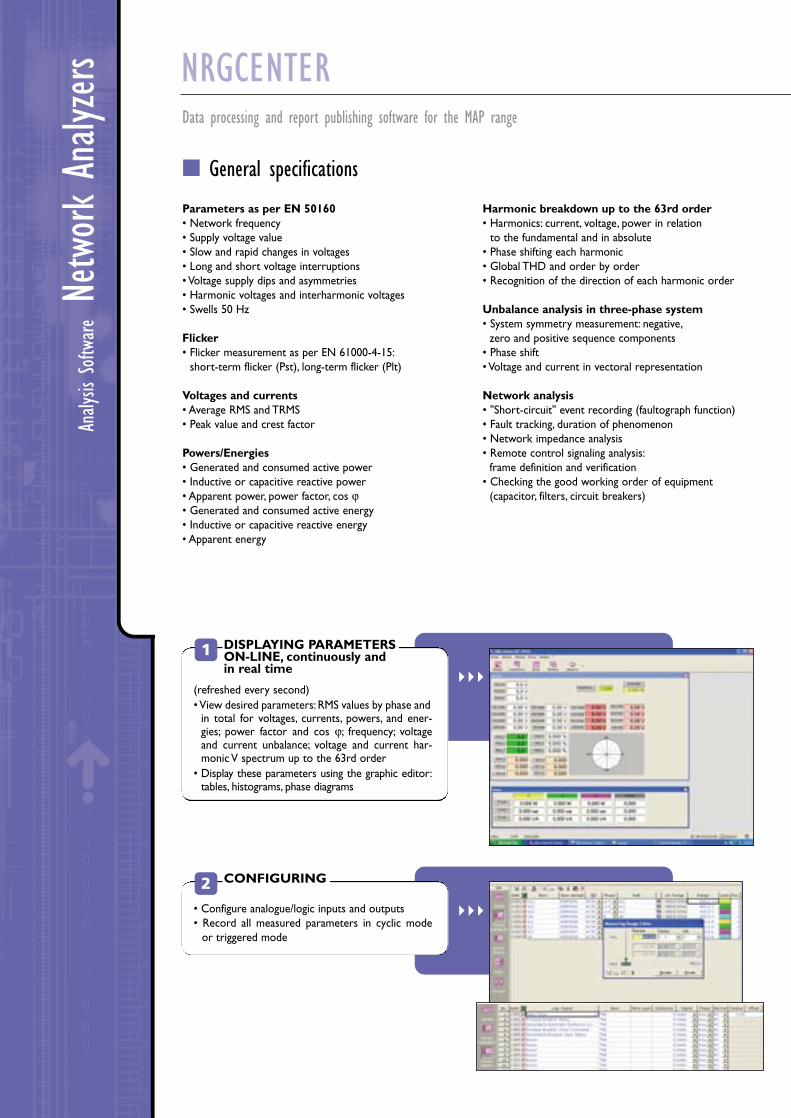
General specifications
Parameters as per EN 50160 • Network frequency• Supply voltage value• Slow and rapid changes in voltages• Long and short voltage interruptions• Voltage supply dips and asymmetries• Harmonic voltages and interharmonic voltages• Swells 50 Hz
Flicker• Flicker measurement as per EN 61000-4-15:
short-term flicker (Pst), long-term flicker (Plt)
Voltages and currents• Average RMS and TRMS• Peak value and crest factor
Powers/Energies• Generated and consumed active power • Inductive or capacitive reactive power • Apparent power, power factor, cos ϕ• Generated and consumed active energy• Inductive or capacitive reactive energy• Apparent energy
Harmonic breakdown up to the 63rd order• Harmonics: current, voltage, power in relation
to the fundamental and in absolute• Phase shifting each harmonic • Global THD and order by order• Recognition of the direction of each harmonic order
Unbalance analysis in three-phase system• System symmetry measurement: negative,
zero and positive sequence components• Phase shift • Voltage and current in vectoral representation
Network analysis• "Short-circuit" event recording (faultograph function)• Fault tracking, duration of phenomenon• Network impedance analysis• Remote control signaling analysis:
frame definition and verification• Checking the good working order of equipment
(capacitor, filters, circuit breakers)
Data processing and report publishing software for the MAP range
1
• Configure analogue/logic inputs and outputs• Record all measured parameters in cyclic mode
or triggered mode
2
DISPLAYING PARAMETERSON-LINE, continuously andin real time
CONFIGURING
(refreshed every second)• View desired parameters: RMS values by phase and
in total for voltages, currents, powers, and ener-gies; power factor and cos ϕ; frequency; voltageand current unbalance; voltage and current har-monic V spectrum up to the 63rd order
• Display these parameters using the graphic editor:tables, histograms, phase diagrams

1213
2410
SELECTION GUIDEINFO & ADVICE
RANGE INFO
3
4
5
• Rapidly publish reports from a library of typicalreports
• Create new reports according to needs automatically• Create EN 50160 standard summary tables
6
ContinuousRECORDING
VIEWING data
EVALUATING & ANALYZINGrecorded data
CREATING reports
- Continuously monitor all desired parameters according to pre-defined detection thresholds:changes in voltage such as swells, dips, interruptions,under-voltages; or other quality parameters such as power factor, available powers, etc.
- Event recording and storing- Triggering an action in parallel: send a message on a
PC or close a relay when the threshold is passed
• Display all recorded parameters in graphic or text format: harmonic distortion, viewing harmonic spectrum up to the 63rd order
• View RMS current, voltage, power values, etc.• View transient recordings
• Distribute duration-values for graphic event classification as per the CBEMA standard
• Analyze voltage networks according to the EN 50160 standard in effect
• Modify monitoring thresholds

ID16
M Ra
ngeNe
twork
Analy
zers ID16M RANGE
Voltage analyzer for MV / LV three-phase network
The ID16 analyzer monitors TRMS voltages on single or three-phase networks, detectsand records interruptions, swells and under-voltages according to the programmed thresholds.
Programming and analysis of recorded events are carried out using WIN ID16 software.
LCD screenfor local programming and viewing
Programmingand reading onmicrocomputeror on front panel
Analyzer comes with WIN ID16software
Description
PRODUCT STRONG POINTS FAULT IDENTIFICATION AND SCHEDULING by type.
RECORDING CAPACITY: 10 x 150-event measurement campaigns.
RESULT ANALYSIS on PC.
AnalyzerID16 M
Analysis softwareWIN ID16

p.16
ASM8: Current load curve analyzer
Associated product
1415
24
ID16MAnalyzer
WIN ID16ANALYSIS SOFTWARE
Measures phase-to-neutral or phase-to-phase TRMS LVor MV voltageHigh and low thresholds: ± 3 % to ± 30 % (step ±1 %)Dip: - 30 % to -80 % (step ±1 %)Interruption: - 80 %Event length: 10 to 990 ms (steps ±10 ms)Memory capacity: 1500 events or 10 campaignsFront display: 4 line, 20 figure screenOutput: EIA 232/JBus™ 1200 to 38400 baudAlarm output: 1 dry contact A/250 V
l’ID16M comes in a hard case containing:• one ID16M instrument• one WinID16 software• measurement leads• PC hook-up lead
• Programs fault detection threshold and fault type • Uses multiple filters for recorded faults• Sorts specific faults, classes then according to
user-selected criteria• Displays and analyzes many campaigns at the same time• Communication on RTC via modem
T O O R D E R
SELECTION GUIDEINFO & ADVICE
Designation ReferenceID16 in hard case IND6 00001
Designation ReferenceWin ID16 Software LOGH 2001

ASM8
Ran
geNe
twork
Analy
zers ASM8 RANGE
Current load curve analyzer for HVA / LV tansformers
ASM8 and ASM8/H61 record the current on each phase for a period of 8 days.They calculate the current in the neutral and determine the unbalance for up to two feeders.The integration period is 10 minutes for RMS measurements and 1 minute formaximum current.You can load measurements in the memory for subsequent display on a PC WinASM8operating software.
Monitors the load of 2 feedersin a HVA / LV transformer
Detects unbalancesvia software supplied with ASM8
Description
PRODUCT STRONG POINTS
PRODUCT SET UP without network shut-down.
OPERATES INDEPENDANTLY on battery (ASM8/H61).
CASING SEALED for outdoor measurements (ASM8/H61).
ASM8/H61outdoor measurements
ASM8indoor measurement
WIN ASM8Software
]1]2

Associated products
1617
24
ASM8
ASM 8
ASM8/H61portable
Designed to meet utilities' require-ments, the ASM8 is a management andoptimization tool for all industrial net-works.With its 6 inputs, the instrumentcan monitor the load of 2 differenttransformers.
It is supplied with a leather carrying caseand six 500/1A clamps, leads andWinASM8 software.
The ASM8/H61 is a portable versiondesigned for measuring runs on LVpower distribution transformers up to160 kVA and is installed under pole-mounted power transformers.
It is supplied with a carrying case and300/1A clamps (3 for 1-feeder model,6 for 2-feeder model), leads andWinASM8 software.
WIN ASM8Analysis software
• ASM8 and ASMO/H61initializationand programming
• Remotely reads measurement campaigns
• Displays tables, histogram or load curve• Displays max values for 1 min• Monitors values for 1sec and 1 min• Saves measurement campaigns
T O O R D E R
SELECTION GUIDEINFO & ADVICE
Designation Reference
ASM8 with clamps ASM8 0002
ASM8 with 6 clamps 500/1A ASM8 0001
1 x C174 clamp 300/1A P01 1203 28
1 x C175 clamp 500/1A P01 1203 29
Designation Reference
ASM8/H61 1 feeder with 3 x 300/1A clamps AS8P 1000
ASM8/H61 2 feeders with 6 x 300/1A clamps AS8P 1001
ASM8/H61 1 feeder with 3 x 500/1A clamps AS8P 1002
ASM8/H61 2 feeders with 6 x 500/1A clamps AS8P 1003
5/1A currentclamp adapter ACCV 1000
Designation Reference
WinASM8 software for ASM8 and ASM8/H61 LOGH 2002
ASM8/H61
p.15
ID16MVoltage analyzer
see EnerdisCatalogue
C173Current clamps

ENERDISFRANCE1-9, rue d'Arcueil - BP 67592542 MONTROUGE CedexTel: +33 1 47 46 78 85Fax: +33 1 47 35 01 [email protected]
ENERDISUNITED KINGDOMChauvin Arnoux LtdWaldeck House - Waldeck RoadMAIDENHEAD SL6 8BRTel: +44 1628 788 888Fax: +44 1628 628 [email protected]
OUR NEW PRODUCTS…
ENERDIS, dedicated to giving youthe best in energy quality and man-agement as well as electrical instal-lation monitoring and safety, is alsocapable of meeting your needs inthe following domains:
Reactive energy compensation Protection relay testing
(any type and function) HVA / HVB circuit breaker testing Tariff metering calibration
REAL ON-SITEMEASUREMENT SERVICE
ENERDIS also is a technical teamthat carries out, on-site, all types of measurements you require fornetwork provisioning, maintenanceand safety.
ENERDIS “Solutions” technical guideElectrical NetworkMonitoring & EnergyManagement
ENERDIS “Product” guidePower Monitors and Remote-operatedelectronic meters
906
211
090
- E
d 0
1 -
03/2
004
- C
hara
cter
istic
s an
d p
ictu
res
are
not
cont
ract
ual