chatter suppression in nc machine tools by cooperative...
TRANSCRIPT
IEEJ International Workshop on Sensing, Actuation, and Motion Control
Chatter Suppression in NC Machine Toolsby Cooperative Control of Spindle and Stage Motors
Satoshi Fukagawa∗a) Student Member, Hiroshi Fujimoto∗ Senior Member
Shinji Ishii∗∗ Non-member, Yuki Terada∗∗ Non-member
The chatter vibration is well known as an undesirable phenomenon, so various methods for the chatter suppressionhave been proposed. To vary the spindle speed in the cutting process is one of the methods for the chatter suppression.However, the chatter vibration like as triangular velocity is not suppressed completely by the method of variable spindlespeed. This remained chatter is caused by that the spindle speed cannot follow the spindle speed reference. Moreover,the triangular spindle speed variation need large torque and good response system of the spindle motor. This paperproposes the method of chatter suppression by a cooperative control of the spindle and the stage motors to decreasethe spindle motor torque. The trajectory and the cooperative control are evaluated by simulations and experiments.Furthermore, as a next work, the spindle speed and the stage speed trajectory to suppress the chatter vibration morethan only the triangular spindle speed variation is proposed.
Keywords: NC Machine tools, Endmilling, Self–excited chatter vibration, Cooperative control
1. Introduction
1.1 Background A machining is exceedingly impor-tant process to produce any product because it is adaptivefor various materials, high precise and much effective. Un-til today, a considerable amount of study has been made onthe NC machine tools to attain higher accuracy and high ef-ficiently in machining(1) (2). Chatter vibration is one of thecauses to be worse the products quality. Chatter vibrationgeneralizes undesired vibration in cutting process. Thus, re-cently the chatter suppression has been focused on and manypapers has been published. Particularly, the tools and workswhich are low stiffness and low damping induces chatter vi-bration. Chatter vibration is classified as self-excited chattervibration or forced chatter vibration.
Especially, self-excited chatter vibration is the most un-desirable, being caused by the interaction between the toolsand works. If the chatter vibration becomes large enough,the system becomes uncontrollable. The methods to sup-press self-excited chatter is divided into four types(3). Two ofthese types analyze the conditions under self-excited chatterdoes not occur, and cuts under these conditions(4) (5). How-ever, these approaches require parameters for the tools, andthe measurement of these parameters requires labor and spec-ified skills.
Furthermore, due to tools being worn down and being de-formed by heat, these parameters are constantly changing,making accurate modeling of the system is difficult. The third
a) Correspondence to: [email protected]∗ The University of Tokyo
5-1-5, Kashiwanoha, Kashiwa, Chiba, 227-8561 Japan∗∗ DMG MORI SEIKI CO., LTD.
2-35-16 Meieki, Nakamura-ku, Nagoya City, Aichi 450-0002,Japan
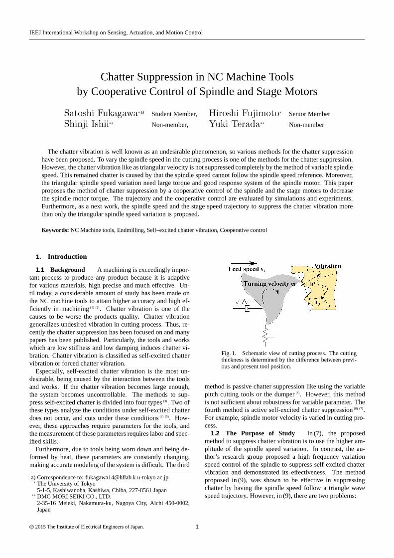
Fig. 1. Schematic view of cutting process. The cuttingthickness is determined by the difference between previ-ous and present tool position.
method is passive chatter suppression like using the variablepitch cutting tools or the dumper(6). However, this methodis not sufficient about robustness for variable parameter. Thefourth method is active self-excited chatter suppression(8) (7).For example, spindle motor velocity is varied in cutting pro-cess.
1.2 The Purpose of Study In (7), the proposedmethod to suppress chatter vibration is to use the higher am-plitude of the spindle speed variation. In contrast, the au-thor’s research group proposed a high frequency variationspeed control of the spindle to suppress self-excited chattervibration and demonstrated its effectiveness. The methodproposed in (9), was shown to be effective in suppressingchatter by having the spindle speed follow a triangle wavespeed trajectory. However, in (9), there are two problems:
c⃝ 2015 The Institute of Electrical Engineers of Japan. 1

Chatter suppression in NC Machine by Cooperative Control (Satoshi Fukagawaet al.)
Fig. 2. Block diagram of self-excited chatter vibration.
( 1 ) The triangle wave speed trajectory requires a discon-tinuous change in motor torque.
( 2 ) The chatter occurs in the point that the spindle speedcannot follow the triangle wave speed trajectory
Therefore in addition to variable spindle speed control, acooperative variable feed speed control is implemented tosolve these problems above in this paper. The followingmethods is proposed:
Proposed methodA velocity trajectory of the spindle and the stage are si-nusoidal wave. This method archives to suppress thechatter vibration and to decrease the required motortorque.
2. The Mechanism of Self-Excited Chatter Vi-bration (9) (10)
Fig. 1 shows the schematic view of cutting process. Here,the variation in relative position of a work and a tool inducesvariation in cutting depth. The variation in cutting thick-ness determines the quality of cutting surface. The cuttingthickness is the difference between the previous tool positionand the present tool position, so the variation in previous cut-ting thickness affects the present cutting thickness. This phe-nomenon is called “regeneration”. Because of the variationin cutting thickness induced by regeneration, the cutting forcechanges. So this variation in cutting force induces variationin cutting thickness. This process consists of unstable closedloop, therefore the self-excited chatter vibration occurs.
Fig. 2 shows the block diagram of self-excited chatter vi-bration(9) (10). Here,a is the width of a tool. Nominal chipthicknessh0 is described as below:
h0 = vs2πω. · · · · · · · · · · · · · · · · · · · · · · · · · · · · · · · · · · · · · · (1)
Here,ω is the spindle speed. Displacement of tooly(t) isexcited by cutting force.
As Fig. 2 shows,h(s) is described as
h(s) = h0(s) + y(s)e−τs − y(s), · · · · · · · · · · · · · · · · · · · · (2)
where,τ is a period of the spindle turning. Then, the thrustcutting forceFn is proportional to the specific cutting forceK f and described as
Fn = aKf h(s). · · · · · · · · · · · · · · · · · · · · · · · · · · · · · · · · · · ·(3)
This cutting force vibrates a work and cases displacementy(s). Therefore, the transfer function from nominal chip
thickness to actual chip thickness is
h(s)h0(s)
=1
1+ (1− e−τs)K f aG(s). · · · · · · · · · · · · · · · · · · (4)
Here,G(s) is the second order lag system shown in Fig. 2and compliance transfer function describes how the machineconstructions vibrate. When the cutting situation is criticalstate, the critical cutting width is defined asalim,and chatterfrequency is definedωc. Then, Eq. (5) is described as
1+ (1− e− jωcτ)K f alim(Re[G(ωc)] + jIm[G(ωc)]) = 0, · · (5)
where, Re[G(ωc)], Im[G(ωc)] are real part ofG(ωc) andimaginary part ofG(ωlim). Thus, both sides of real part andimaginary part are equal. Critical cutting widthalim is com-pute as:
alim =
∣∣∣∣∣∣ 12K f Re[G(ωc)]
∣∣∣∣∣∣ . · · · · · · · · · · · · · · · · · · · · · · · · · (6)
Equation. (6) shows that compliance of the machine structureRe[G(ωc)] is in inverse proportion to critical cutting widthalim.
3. Methods of Chatter Suppression
As shown in the previous section, the mechanism of theself-excited chatter vibration is that the periodic change ofcutting thickness induces the periodic change of cuttingforce. In a previous study, it was proposed that the variablespindle speed suppressed the chatter vibration. Moreover,in the authors research group, the method of high frequencyspindle speed variation was proposed and the effect for chat-ter suppression was confirmed(9). In this paper, this methodis regarded as a conventional method. And in this section,the conventional method is mentioned and then the proposedmethod is mentioned.
3.1 Chatter suppression by High Frequency SpindleSpeed Variation(conventional method) In this subsec-tion, the method of chatter suppression by high frequencyspindle speed variation(9) is introduced. To generalize ampli-tude and frequency of spindle speed variation, the parametersARVA and fRVF are defined as follows
ARVA=NA
Nav, · · · · · · · · · · · · · · · · · · · · · · · · · · · · · · · · · · · · (7)
fRVF =2π
NavT. · · · · · · · · · · · · · · · · · · · · · · · · · · · · · · · · · · (8)
Here,T is the period of variation in spindle speed,Nav is theaverage of spindle speed, andNA is the maximum value ofspindle speed. The variation in the spindle speed changesthe wave–number on cutting surface caused by vibration ofthe tool in cutting of each teeth. Accordingly, the periodicvariation in cutting thickness is disturbed by change in thespindle speed. Thus, chatter vibration is suppressed. More-over, it is mentioned that the triangular velocity trajectory iseffective for chatter suppression in (9) because to change thewave–number on cutting surface constantly is important tosuppress chatter vibration.
3.2 Chatter Suppression by the Sinusoidal Veloc-ity Trajectory Cooperative Control (proposed method)The triangular velocity trajectory(9) of spindle needs discon-
2

Chatter suppression in NC Machine by Cooperative Control (Satoshi Fukagawaet al.)
Fig. 3. The definition of nominal cutting thickness.Cs andPs are the stage controller and plant.Cω andPω arethe spindle controller and plant. The nominal cutting thickness is defined by feed speedvs andω
Sp
ind
le, st
age
vel
oci
ty
Time
Feed
Spindle
�
Fig. 4. Sinusoidal velocity trajectory cooperative con-trol (proposed method). The spindle and the stage veloc-ity are sinusoidal. There is phase difference between thespindle speed and the feed speed.
tinuous variation in motor torque, so that the bigger powermotor is required. The bigger motors need more expense.Also it is difficult to track the triangular velocity trajectory, sosynchronous motor was used as the spindle motor in (9). Al-though synchronous motors good in tracking control, usuallyinduction motors are used for most of machine tools. There-fore, this paper proposes cooperative control of spindle andstage and these speed trajectory are sinusoidal. Fig. 4 showsthe conceptual diagram. The spindle and the feed speed issinusoidal and additionally, there is phase difference betweenthe spindle speed and the feed speed. This proposed methoddoes not requires discontinuous variation in motor torque ofspindle. Moreover, when the ratio of spindle speed variationis small, the feed speed changes and then varies cutting thick-ness.
4. Simulation of Chatter Suppression
To simulate the suppression of chatter vibration, cuttingthickness is defined as below and the block diagram is shownFig. 3. The nominal cutting thicknessh0(t) is
h0(t) = vs(t)2πω(t), · · · · · · · · · · · · · · · · · · · · · · · · · · · · · · · · · · (9)
the spindle speedω(t) is
ω(t) = ωav + AspindleωavSspindle( fspindle, t), · · · · · · · · · · · (10)
and the feed speedvs(t) is
vs(t) = vs av + AstagevavSstage( fstage, t). · · · · · · · · · · · · · · · (11)
Table 1. Reference parameter for simulation.
Parameter Valueωav 262 rad/s
Aspindle 0.3fspindle 0.7vs av 2 mm/sAstage 0.1
Table 2. Model parameter for simulation.
Parameter ValueWidth of cuta 5 mm
Specific cutting forceK f 300 MpaDynamic massM 10 Ns2/m
Mechanical impedanceB 200 Ns/mDynamic rigidityK 5× 10⁵N/m
Here,ωav is the mean value of spindle speed,Aspindle is theamplitude coefficient of the spindle speed variation definedin Eq. (7), Sspindle( fspindle, t) is the shape function of spin-dle speed trajectory andfspindle is the frequency coefficientof spindle speed variation defined in Eq. (8). For example,Sspindle( fspindle, t) in Eq. (8) is trigonometric function or trian-gle wave. In the same way,vs av is the average of feed speed,Astage is the amplitude coefficient of the feed speed variation,Sstage( fspindle, t) is the shape function of stage speed trajectoryand fstage is the frequency coefficient of stage speed variation.Fig. 2 also is used for simulation, and Eq. (9) – (11) are usedto compute the valuable nominal cutting thickness and Eq.(10) is used to computeτ. Theτ is a period of the spindleturning. Therefore, in Fig. 2,τ is changed approximatelydepending on time.
4.1 Simulation by Sinusoidal Velocity Trajectory Co-operative Control (Proposed Method) This proposedmethod used sinusoidal velocity trajectory. The spindle andthe feed speed are defined as below:
ω(t) = ωav + Aspindleωav sin (fspindleωavt), · · · · · · · · (12)
vs(t) = vav + Astagevav sin (fstageωavt − ϕ). · · · · · · · · · (13)
Here,ϕ is phase difference between the spindle speed andthe stage speed and the simulation parameter is Table. 1. Theoptimal point offstage, ϕ are decided by simulation of the eachcondition fstage from 0 to 1 andϕ from 0 to 2π. The fstage, ϕ
3

Chatter suppression in NC Machine by Cooperative Control (Satoshi Fukagawaet al.)
Fig. 5. Chatter vibration simulation dependence offstage
and phase shift by sinusoidal trajectory when the spindleRVF = 0.7. Chatter vibration tends to suppress aroundphase shift= π/2 and RVF= 0.7
0 0.02 0.04 0.06 0.08 0.1 0.12−2
−1
0
1
2
3x 10
−3
time t [s]
chat
ter
h [
mm
]
only spindle
spindle and stage
Fig. 6. Chatter vibration simulation by sinusoidal tra-jectory (time–dependent). Some peaks of chatter vibra-tion are suppressed.
101
102
103
0
0.5
1
1.5
2
2.5
3
3.5x 10
�4
Frequency [Hz]
chat
ter
h [
mm
]
only spindle
spindle and stage
Fig. 7. Chatter vibration simulation by sinusoidal tra-jectory (FFT). The chatter vibration around 100 Hz issuppressed.
dependence of chatter vibration given by the simulation isFig. 5. This result explains that the chatter vibration tends tobe suppressed aroundϕ = π/2 and fstage = 0.7. Moreover, inthis optimal parameters ofϕ = π/2 and fstage = 0.7, the timedependent simulation and FFT results are shown in Fig 6, 7.The reference parameters of this simulation are shown in Ta-ble.1. Table. 2 is Model parameter used in this simulation.In Fig. 7, the vibration around 30 Hz are caused by the vari-ation in the speed of spindle and the feed. Now, the resonantfrequency of the plant model used for simulation is about 112
Fig. 8. Experimental setup.
Table 3. The reference parameters for experiment.
Parameter Valueωav 90 rad/s
Aspindle 0.1fspindle 0.5vs av 0.5 mm/sAstage 0.2fstage 0.5
Table 4. The spindle and the stage parameters.
Parameter ValueJspindle 6.8× 10⁻³ kg ·m2
Dspindle 7.8× 10⁻³ Nm · sKt spindle 0.47 NmA
Jstage 8.5× 10⁻³ kg ·m2
Dstage 1.4 Nm · sKt stage 0.715 Nm/A
Table 5. Cutting condition.
Parameter ValueEnd mill flutes 2
End mill ϕ 20 mmRadial depth of cut 5 mmAxial depth of cut 20 mm
Work piece C1100
Hz. It is known that the chatter vibration occurs around res-onant frequency of the plant model(10). The chatter vibrationfrequency around 112 Hz is suppressed by proposed method.
5. Controlled System
Fig. 8 shows the experimental equipment. In this paper,the spindle and the stage used velocity controller. The spin-dle and the stage models are described as transfer functionbelow
G(s) =Kt
Js+ D. · · · · · · · · · · · · · · · · · · · · · · · · · · · · · · · · (14)
The parameters of the spindle and the stage are shown in Ta-ble. 4. Here, subscript “spindle” means the parameters of the
4

Chatter suppression in NC Machine by Cooperative Control (Satoshi Fukagawaet al.)
Fig. 9. Experimental result FFT. The vibration from 580Hz to 700 Hz is suppressed.
Fig. 10. The experimental spindle speed of proposedmethod in (9). The response cannot track the referenceat top of triangle spindle speed trajectory.
spindle and “stage” means the parameters of the stage. ThePI controllers are used in both systems, and the pole assign-ment of the spindle is 50 Hz and the stage is 40 Hz. Then, thestage system is semi closed loop control.
6. Experimental Results
In this section, the proposed method is evaluated by ex-periments. The efficacy of the proposed method is evaluatedby cutting experiment. The reference parameters are shownin Table. 3 and the cutting conditions are shown in Table.5. The efficacy is evaluated by using the acceleration sen-sor. The the result of the cutting experiment is shown in Fig.9. In Fig. 9, the waves shows FFT of acceleration. Thepink and broken line shows the acceleration of the spindlewith the spindle speed and the stage speed are constant. Thegreen and broken line shows the acceleration with the spindlespeed is sinusoidal trajectory and stage speed is constant. Theblue line shows the acceleration with proposed method. Thespindle and the stage have the phase difference ofπ/2. Asshown in Fig. 9, the chatter vibration appears from 580 Hzto 700 Hz. Then, compared between the proposed methodand constant, the chatter vibration are much suppressed byproposed method. Furthermore, compared between the pro-posed method and the conventional, the chatter vibration aresuppressed especially from 600 Hz to 700 Hz.
Time
Sp
ind
le, st
age
vel
oci
ty
Tstage
Tspindle
Spindle
Feed
vs_av � Astage
Response
Reference
Fig. 11. Triangular velocity trajectory cooperative con-trol (proposed method). The spindle and the stage ve-locity are triangular. When the spindle speed does notchange, the stage is moved.
0 0.02 0.04 0.06 0.08 0.1 0.122
1
0
1
2
3x 10
�3
time t [s]
chat
ter
h [
mm
]
only spindle
spindle and stage
Fig. 12. Chatter vibration by triangular trajectory(time–dependent). Some peaks of chatter vibration aresuppressed.
101
102
103
0
0.5
1
1.5
2
2.5
3
3.5x 10
�4
Frequency [Hz]
chat
ter
h [
mm
]
only spindle
spindle and stage
Fig. 13. Chatter vibration by triangular trajectory(FFT). The chatter vibration around 100 Hz is sup-pressed.
7. Another Trajectory as Next Works
In this section, another trajectory of the stage and the spin-dle is also proposed and simulated as next works.
7.1 Triangular Velocity Trajectory Cooperative Con-trol (Next Proposed Method) The chatter vibration isnot completely suppressed in (9). The reason is the spindlespeed cannot follow the triangle wave speed trajectory. Theremained chatter occurs in the point that the spindle speedcannot follow the triangular spindle speed reference. The ex-perimental wave of spindle speed is shown in Fig. 10. At thetop of triangular wave, the rate of the change in the spindlespeed is zero, so that the wave–number on cutting surface isnot varied in each cut and that induces periodic vibration in
5

Chatter suppression in NC Machine by Cooperative Control (Satoshi Fukagawaet al.)
Table 6. Characters of each method.
Only spindle variation Sinusoidal cooperation (Proposed) Triangle cooperation (Next proposed)Chatter suppression Good Good Very good
Motor torque Normal Small Normal
cutting thickness. Thus, the chatter vibration occurs. Sup-pressing chatter vibration, it is essential to vary cutting thick-ness constantly.
Hence, At the point that the spindle speed cannot followthe triangle wave speed trajectory, the feed speed is changedto suppress chatter vibration more than only spindle speedvariation. This conceptual diagram is shown Fig. 11. Here,a broken and red line shows the spindle speed and blue oneshows the feed speed. As shown Fig. 11, the feed speedis changed when the rate of the variation in spindle speed iszero. The aim of this method is to change cutting thicknessirregularly at all times.
7.2 Simulation by Triangular Velocity Trajectory Co-operative Control (Next Proposed Method) The sim-ulation model is Fig. 2. Reference parameters are shown inTable.1 and Table. 2. Additionally,Tspindle= 0.171 s,Tstage =
0.0342 s. Fig. 12 shows the simulation result of time–dependent chatter vibration by the triangular velocity trajec-tory. The red and broken line shows the chatter vibrationhwith the variation in just spindle. The blue one is with thevariation in both the spindle and the stage. As shown in Fig.13 which is the FFT graph of Fig. 12, the chatter vibrationsaround 112 Hz witch is resonant frequency are more sup-pressed by the sinusoidal velocity trajectory cooperative con-trol. Here, the vibrations around 30 Hz are caused by activevariation in the spindle and the feed speed.
8. Conclusion
In this paper, the cooperative control between the spindlespeed and stage speed for self–excited chatter suppression isproposed. The proposed method using sinusoidal velocitytrajectory is evaluated by simulations and experiments. It iseffective to suppress the chatter vibration and decrease thediscontinuous variation in motor torque. Moreover, it is pos-sible that induction motors, which usually used for productsof machine tools can track the sinusoidal reference. This pro-posed method archives to save cost of machine tools.
The method of spindle and stage velocity trajectory us-ing triangle trajectory is also evaluated as next works. Thismethod evaluated by simulation. The simulation shows ef-fectiveness for chatter suppression more than the spindle ve-locity triangular variation and cooperative sinusoidal velocitytrajectory.
The characters of the proposed methods are shown in Ta-ble. 6. If to decrease motor torques is required, the sinusoidalvelocity trajectory cooperative variation is selected. If morehigh precision products and decreasing chatter more than si-nusoidal speed variation, the triangular cooperative variationis chosen.
As the future works, triangular velocity trajectory cooper-ative control is going to be experiment. Moreover, it is nec-essary to optimize the spindle speed and the feed speed tra-jectory. The frequency response is going to analyzed and the
variation in spindle and stage velocity will optimized. Opti-mization of the spindle and feed speed variation is going tomake more chatter suppression.
References
( 1 ) A. Matsubara, & S. Ibaraki “Proposal of fast and high-precision control forball-screw-driven stage by explicitly considering elastic deformation, ” Ad-vanced Motion Control (AMC), (2014)
( 2 ) Z. Hongzhong, & H. Fujimoto, “Monitoring and Control of Cutting Forcesin Machining Processes: A Review, ” Int. J. of Automation Technology, Vol.3, No. 4 (2009)
( 3 ) G. Quintana, & J. Ciurana, “Chatter in machining processes: A review, ”International Journal of Machine Tools and Manufacture 51.5, pp. 363–376(2011)
( 4 ) Altintas. Y, & E. Budak, “Analytical prediction of stability lobes in milling,” CIRP Annals-Manufacturing Technology 44.1, pp. 357–362 (1995)
( 5 ) H. Cao, B. Li, & Z. He, “Chatter stability of milling with speed-varying dy-namics of spindles, ” International Journal of Machine Tools and Manufac-ture 52.1, pp. 50–58 (2012)
( 6 ) J. Munoa, I. Mancisidor, N. Loix, L. G. Uriarte, R. Barcena, & M. Zatarain,“Chatter suppression in ram type travelling column milling machines usinga biaxial inertial actuator, ” CIRP Annals-Manufacturing Technology, 62(1),pp. 407–410. (2013)
( 7 ) S. Seguy, T. Insperger, L. Arnaud, G. Dessein & G. Peigne,“SUPPRESSIONOF PERIOD DOUBLING CHATTER IN HIGH – SPEED MILLING BYSPINDLE SPEED VARIATION, ” Journal of Machining Science and Tech-nology, Vol. 15, pp.153–171(2011)
( 8 ) Y. Kakinuma, K. Enomoto, T. Hirano, & K. Ohnishi, “Active chatter suppres-sion in turning by band-limited force control, ” CIRP Annals-ManufacturingTechnology, 63(1), pp. 365–368 (2014)
( 9 ) T. Ishibashi, H. Fujimoto, S. Ishi, K. Yamamoto, & Y. Terada, “High–frequency–variation speed control of spindle motor for chatter vibration sup-pression in NC machine tools, ” In American Control Conference (ACC),pp2172–2177 (2014)
(10) E. Shamoto, “Mechanism and Suppression of Chatter VIbrations in Cutting,” Electric Furnace Steel, Vol. 82, No. 2, pp. 143-155(2011)(in Japanese)
6