characterization ofsector clock biases incellularcdma systems
TRANSCRIPT
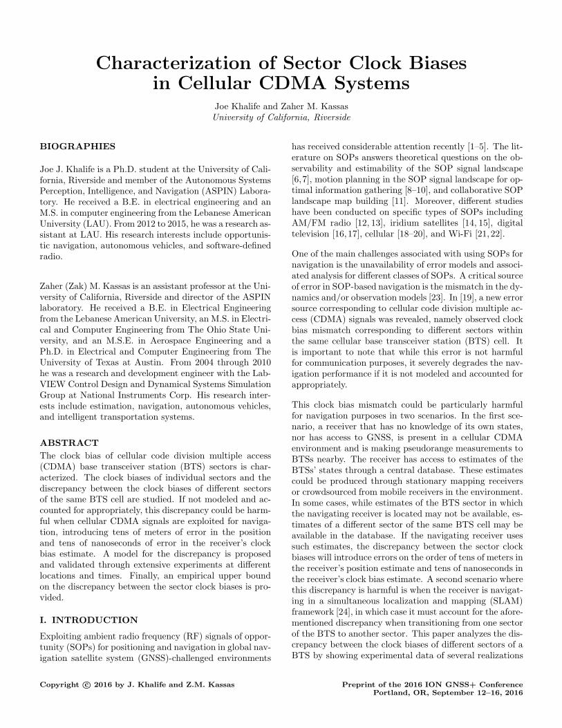
Characterization of Sector Clock Biasesin Cellular CDMA Systems
Joe Khalife and Zaher M. KassasUniversity of California, Riverside
BIOGRAPHIES
Joe J. Khalife is a Ph.D. student at the University of Cali-fornia, Riverside and member of the Autonomous SystemsPerception, Intelligence, and Navigation (ASPIN) Labora-tory. He received a B.E. in electrical engineering and anM.S. in computer engineering from the Lebanese AmericanUniversity (LAU). From 2012 to 2015, he was a research as-sistant at LAU. His research interests include opportunis-tic navigation, autonomous vehicles, and software-definedradio.
Zaher (Zak) M. Kassas is an assistant professor at the Uni-versity of California, Riverside and director of the ASPINlaboratory. He received a B.E. in Electrical Engineeringfrom the Lebanese American University, an M.S. in Electri-cal and Computer Engineering from The Ohio State Uni-versity, and an M.S.E. in Aerospace Engineering and aPh.D. in Electrical and Computer Engineering from TheUniversity of Texas at Austin. From 2004 through 2010he was a research and development engineer with the Lab-VIEW Control Design and Dynamical Systems SimulationGroup at National Instruments Corp. His research inter-ests include estimation, navigation, autonomous vehicles,and intelligent transportation systems.
ABSTRACT
The clock bias of cellular code division multiple access(CDMA) base transceiver station (BTS) sectors is char-acterized. The clock biases of individual sectors and thediscrepancy between the clock biases of different sectorsof the same BTS cell are studied. If not modeled and ac-counted for appropriately, this discrepancy could be harm-ful when cellular CDMA signals are exploited for naviga-tion, introducing tens of meters of error in the positionand tens of nanoseconds of error in the receiver’s clockbias estimate. A model for the discrepancy is proposedand validated through extensive experiments at differentlocations and times. Finally, an empirical upper boundon the discrepancy between the sector clock biases is pro-vided.
I. INTRODUCTION
Exploiting ambient radio frequency (RF) signals of oppor-tunity (SOPs) for positioning and navigation in global nav-igation satellite system (GNSS)-challenged environments
has received considerable attention recently [1–5]. The lit-erature on SOPs answers theoretical questions on the ob-servability and estimability of the SOP signal landscape[6,7], motion planning in the SOP signal landscape for op-timal information gathering [8–10], and collaborative SOPlandscape map building [11]. Moreover, different studieshave been conducted on specific types of SOPs includingAM/FM radio [12, 13], iridium satellites [14, 15], digitaltelevision [16, 17], cellular [18–20], and Wi-Fi [21, 22].
One of the main challenges associated with using SOPs fornavigation is the unavailability of error models and associ-ated analysis for different classes of SOPs. A critical sourceof error in SOP-based navigation is the mismatch in the dy-namics and/or observation models [23]. In [19], a new errorsource corresponding to cellular code division multiple ac-cess (CDMA) signals was revealed, namely observed clockbias mismatch corresponding to different sectors withinthe same cellular base transceiver station (BTS) cell. Itis important to note that while this error is not harmfulfor communication purposes, it severely degrades the nav-igation performance if it is not modeled and accounted forappropriately.
This clock bias mismatch could be particularly harmfulfor navigation purposes in two scenarios. In the first sce-nario, a receiver that has no knowledge of its own states,nor has access to GNSS, is present in a cellular CDMAenvironment and is making pseudorange measurements toBTSs nearby. The receiver has access to estimates of theBTSs’ states through a central database. These estimatescould be produced through stationary mapping receiversor crowdsourced from mobile receivers in the environment.In some cases, while estimates of the BTS sector in whichthe navigating receiver is located may not be available, es-timates of a different sector of the same BTS cell may beavailable in the database. If the navigating receiver usessuch estimates, the discrepancy between the sector clockbiases will introduce errors on the order of tens of meters inthe receiver’s position estimate and tens of nanoseconds inthe receiver’s clock bias estimate. A second scenario wherethis discrepancy is harmful is when the receiver is navigat-ing in a simultaneous localization and mapping (SLAM)framework [24], in which case it must account for the afore-mentioned discrepancy when transitioning from one sectorof the BTS to another sector. This paper analyzes the dis-crepancy between the clock biases of different sectors of aBTS by showing experimental data of several realizations
Copyright c© 2016 by J. Khalife and Z.M. Kassas Preprint of the 2016 ION GNSS+ ConferencePortland, OR, September 12–16, 2016

of this discrepancy and of its process noise over differenttime and locations.
The remainder of the paper is organized as follows. Sec-tion II discusses the discrepancy between sector clock bi-ases. Section III describes the hardware setup and theenvironments in which the data was collected. Section IVpresents experimental results characterizing the discrep-ancy between the clock biases observed in different sectorsof the same BTS. Concluding remarks are given in SectionV.
II. CLOCK BIAS ESTIMATION AND SECTOR
CLOCK BIAS DISCREPANCY
This section discusses the estimation of the sector clockbias and the observed discrepancy between the clock biasesof different sectors of a BTS cell.
A. Clock Bias Estimation
A cellular CDMA receiver is assumed to be drawing pseu-dorange measurements from the nearby BTSs. The state
of the receiver is defined as xr ,[
rrT, cδtr
]T
, where rr =
[xr, yr]T is the position vector of the receiver, δtr is the
receiver’s clock bias, and c is the speed-of-light. Similarly,
the state of the ith BTS is defined as xsi ,[
rsiT, cδtsi
]T
,
where rsi = [xsi , ysi ]Tis the position vector of the ith BTS
and δtsi is the clock bias. The pseudorange measurementto the ith BTS at time k, ρi(k), is given by
ρi(k) = ‖rr(k)− rsi‖+ c · [δtr(k)− δtsi(k)] + vi(k), (1)
where vi is the observation noise, which is modeled as azero-mean white Gaussian random sequence with varianceσ2i [25]. Knowing the receiver’s position and clock states
(from GPS, for example) and the BTS position (throughprior mapping, surveying, or database access), the clockbias of the BTS can be readily estimated.
B. Clock Bias in Different Sectors of the Same
BTS Cell
Ideally, the clocks of all sectors within a particular BTScell should be driven by the same oscillator, which impliesthat the same clock bias should be observed in all sectorsof the same cell. However, factors such as unknown dis-tance between the phase-center of the sector antennas anddelays due to radio frequency (RF) connectors and othercomponents (e.g., cabling, filters, amplifiers, etc.) causethe clock biases corresponding to different BTS sectors tobe slightly different. This behavior was consistently ob-served in experimentally collected data. In order to detectthe discrepancy between sectors’ clock biases, a cellular
CDMA receiver was placed on the border of sectors pi andqi of a BTS cell and was drawing pseudorange measure-ments from both sector antennas. The receiver had fullknowledge of its state and of the BTS’s position. Subse-
quently, the receiver solved for the BTS clock biases δt(pi)si
and δt(qi)si observed in sectors pi and qi, respectively. A
realization of δt(pi)si and δt
(qi)si is depicted in Fig. 1.
Sector pi
Sector qi
Time [s]
Sector piSector qi
Observedclockbiases
for
SectorAntenna
ith BTS Cell(a) (b)
differentBTSsectors[s]
Fig. 1. (a) A receiver placed on the border of sectors pi and qi of theith BTS, making pseudorange observations on the sector antennassimultaneously. In this scenario, the receiver has knowledge of itsown states and has knowledge of the BTS’s position. (b) ObservedBTS clock biases corresponding to two different sectors.
Fig. 1 suggests that the clock biases δt(pi)si and δt
(qi)si can
be related through
cδt(qi)si(k) = cδt(pi)
si(k) + [1− 1qi(pi)] ǫi(k),
where ǫi is a random sequence that models the discrepancybetween the sectors’ clock biases and
1qi(pi) =
{
1, if pi = qi,
0, otherwise,
is the indicator function.
C. Clock Bias Discrepancy Dynamic Model
From what has been consistently observed in experimentaldata, it is hypothesized that the discrepancy between theclock biases of different sectors of the same BTS behavesas a random walk. Subsequently, it can be modeled as
ǫi(k + 1) = ǫi(k) + ζ(k), (2)
where ζ, referred to as the process noise, is a white randomsequence.
III. TEST ENVIRONMENTS AND HARDWARE
SETUP
This section discusses the environments in which the ex-periments were conducted as well as the hardware setup.
2

A. Cellular CDMA SOP Test Scenarios
The tests were performed twice at three different locations.There is a six day period between each test at each of thethree locations. A total of three carrier frequencies wereconsidered, two of them pertaining to VerizonWireless andone to Sprint. The test scenarios are summarized in TableI and Fig. 2. The date field in Table I shows the date inwhich the test was conducted in MM/DD/YYYY format.
TABLE I
Test Dates, Locations, and Carrier Frequencies
Test Date Location Frequency Provider
(a) 01/14/2016 1 882.75 MHz Verizon
(b) 01/20/2016 1 882.75 MHz Verizon
(c) 08/28/2016 2 883.98 MHz Verizon
(d) 09/02/2016 2 883.98 MHz Verizon
(e) 08/28/2016 3 1940.0 MHz Sprint
(f) 09/02/2016 3 1940.0 MHz Sprint
Location 1
Location 2
Location 3
Colton
Riverside
UCR
BTS 1
BTS 2
BTS 3 2Km
Fig. 2. Locations of the cellular CDMA BTSs. Colton, CA; River-side, CA; and the University of California, Riverside (UCR).
B. Hardware Setup
For the purpose of collecting data, a receiver that wasplaced close to the border of two sectors for each BTSwas equipped with two antennas to acquire and track: (1)GPS signals and (2) signals from the cellular CDMA BTSsector antennas. The CDMA antenna used for the experi-ments in location 1 was a consumer-grade 800/1900 MHzcellular antenna and a high-gain tri-band cellular antennafor locations 2 and 3. Both GPS antennas were surveyor-grade Leica antennas. The GPS and cellular signals were
simultaneously down-mixed and synchronously sampled at2.5 MS/s via a dual channel universal software radio pe-ripheral (USRP) driven by a GPS-disciplined oscillator.Samples of the received signals were stored for off-line post-processing. The GPS signal was processed by a General-ized Radionavigation Interfusion Device (GRID) SDR [26]and the cellular CDMA signals were processed by the cel-lular CDMA module of the LabVIEW-based MultichannelAdaptive Transceiver Information Extractor (MARTRIX)SDR [19]. The receiver’s clock bias obtained from the GPSsolution was used to solve for the BTS sector clock bias.Fig. 3 shows the experimental hardware setup.
GPS Antenna
CDMAAntenna
USRP
Storage
Laptop+
CDMAAntenna
GPS Antenna
Location 1Locations 2 & 3
Fig. 3. Experimental hardware setup for each location. Left: hard-ware setup for locations 2 and 3. Center: data collection equipment.Right: hardware setup for location 1.
IV. BTS SECTORS CLOCK BIAS DISCREP-
ANCY CHARACTERIZATION
This section provides extensive experimental data thatvalidate the sector clock bias discrepancy dynamic modelgiven in (2).
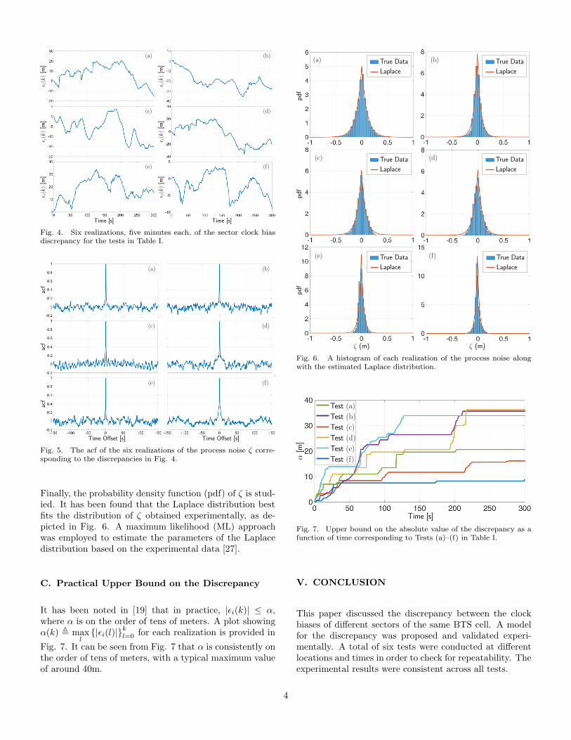
A. Realizations of the Discrepancy
Fig. 4 shows six realizations, five minutes each, of the dis-crepancy corresponding to Tests (a)–(f) in Table I. It canbe seen from Fig. 4 that the behaviour of the discrepancyis consistent across the tests. The initial discrepancy issubtracted out so that all realizations start at the origin.
B. Realizations of the Discrepancy Process Noise
Next, the process noise driving the discrepancy is charac-terized. The process noise sequence was calculated accord-ing to
ζ(k) = ǫi(k)− ǫi(k − 1),
where ǫi is the measured discrepancy. The autocorrelationfunction (acf) of each of the six realizations of ζ corre-sponding to the six realizations of ǫi from Fig. 4 are shownin Fig. 5. The shape of the acfs in Fig. 5 exhibits veryquick de-correlation, implying that ζ is approximately awhite sequence.
3
Time [s] Time [s]
ǫi(k)[m
]ǫi(k)[m
]ǫi(k)[m
]
ǫi(k)[m
]ǫi(k)[m
]
(a)
(c)
(e) (f)
(d)
(b)
ǫi(k)[m
]
Fig. 4. Six realizations, five minutes each, of the sector clock biasdiscrepancy for the tests in Table I.
Time Offset [s]
(f)
(d)
(b)
Time Offset [s]
acf
(a)
(c)
(e)
acf
acf
Fig. 5. The acf of the six realizations of the process noise ζ corre-sponding to the discrepancies in Fig. 4.
Finally, the probability density function (pdf) of ζ is stud-ied. It has been found that the Laplace distribution bestfits the distribution of ζ obtained experimentally, as de-picted in Fig. 6. A maximum likelihood (ML) approachwas employed to estimate the parameters of the Laplacedistribution based on the experimental data [27].
C. Practical Upper Bound on the Discrepancy
It has been noted in [19] that in practice, |ǫi(k)| ≤ α,where α is on the order of tens of meters. A plot showingα(k) , max
l{|ǫi(l)|}
k
l=0 for each realization is provided in
Fig. 7. It can be seen from Fig. 7 that α is consistently onthe order of tens of meters, with a typical maximum valueof around 40m.
ζ (m)
True Data
Laplace
True Data
Laplace
True Data
Laplace
True Data
Laplace
(a) (b)
(d)(c)
True Data
Laplace
True Data
Laplace
(f)(e)
ζ (m)
Fig. 6. A histogram of each realization of the process noise alongwith the estimated Laplace distribution.
Test (a)
Test (b)
Test (c)
Test (d)
Test (e)
Test (f)
Time [s]
α[m
]
Fig. 7. Upper bound on the absolute value of the discrepancy as afunction of time corresponding to Tests (a)–(f) in Table I.
V. CONCLUSION
This paper discussed the discrepancy between the clockbiases of different sectors of the same BTS cell. A modelfor the discrepancy was proposed and validated experi-mentally. A total of six tests were conducted at differentlocations and times in order to check for repeatability. Theexperimental results were consistent across all tests.
4

Acknowledgment
This work was supported in part by the Office of NavalResearch (ONR) under Grant N00014-16-1-2305.
References
[1] J. McEllroy, J. Raquet, and M. Temple, “Use of a software radioto evaluate signals of opportunity for navigation,” in Proceed-ings of ION GNSS Conference, September 2006, pp. 126–133.
[2] J. Raquet and R. Martin, “Non-GNSS radio frequency nav-igation,” in Proceedings of IEEE International Conference onAcoustics, Speech and Signal Processing, March 2008, pp. 5308–5311.
[3] L. Merry, R. Faragher, and S. Schedin, “Comparison of oppor-tunistic signals for localisation,” in Proceedings of IFAC Sym-posium on Intelligent Autonomous Vehicles, September 2010,pp. 109–114.
[4] Z. Kassas, “Collaborative opportunistic navigation,” IEEEAerospace and Electronic Systems Magazine, vol. 28, no. 6, pp.38–41, 2013.
[5] ——, “Analysis and synthesis of collaborative opportunisticnavigation systems,” Ph.D. dissertation, The University ofTexas at Austin, USA, 2014.
[6] Z. Kassas and T. Humphreys, “Observability analysis of oppor-tunistic navigation with pseudorange measurements,” in Pro-ceedings of AIAA Guidance, Navigation, and Control Confer-ence, vol. 1, August 2012, pp. 1209–1220.
[7] ——, “Observability and estimability of collaborative oppor-tunistic navigation with pseudorange measurements,” in Pro-ceedings of ION GNSS Conference, September 2012, pp. 621–630.
[8] ——, “Motion planning for optimal information gathering in op-portunistic navigation systems,” in Proceedings of AIAA Guid-ance, Navigation, and Control Conference, August 2013, 551–4565.
[9] Z. Kassas, A. Arapostathis, and T. Humphreys, “Greedy mo-tion planning for simultaneous signal landscape mapping andreceiver localization,” IEEE Journal of Selected Topics in Sig-nal Processing, vol. 9, no. 2, pp. 247–258, March 2015.
[10] Z. Kassas and T. Humphreys, “Receding horizon trajectoryoptimization in opportunistic navigation environments,” IEEETransactions on Aerospace and Electronic Systems, vol. 51,no. 2, pp. 866–877, April 2015.
[11] ——, “The price of anarchy in active signal landscape mapbuilding,” in Proceedings of IEEE Global Conference on Sig-nal and Information Processing, December 2013, pp. 165–168.
[12] J. McEllroy, “Navigation using signals of opportunity in theAM transmission band,” Master’s thesis, Air Force Institute ofTechnology, Wright-Patterson Air Force Base, Ohio, USA, 2006.
[13] S. Fang, J. Chen, H. Huang, and T. Lin, “Is FM a RF-based po-sitioning solution in a metropolitan-scale environment? A prob-abilistic approach with radio measurements analysis,” IEEETransactions on Broadcasting, vol. 55, no. 3, pp. 577–588,September 2009.
[14] M. Joerger, L. Gratton, B. Pervan, and C. Cohen, “Analysis ofIridium-augmented GPS for floating carrier phase positioning,”NAVIGATION, Journal of the Institute of Navigation, vol. 57,no. 2, pp. 137–160, 2010.
[15] K. Pesyna, Z. Kassas, and T. Humphreys, “Constructing a con-tinuous phase time history from TDMA signals for opportunis-tic navigation,” in Proceedings of IEEE/ION Position Locationand Navigation Symposium, April 2012, pp. 1209–1220.
[16] M. Rabinowitz and J. Spilker, Jr., “A new positioning systemusing television synchronization signals,” IEEE Transactions onBroadcasting, vol. 51, no. 1, pp. 51–61, March 2005.
[17] P. Thevenon, S. Damien, O. Julien, C. Macabiau, M. Bousquet,L. Ries, and S. Corazza, “Positioning using mobile TV basedon the DVB-SH standard,” NAVIGATION, Journal of the In-stitute of Navigation, vol. 58, no. 2, pp. 71–90, 2011.
[18] C. Yang, T. Nguyen, and E. Blasch, “Mobile positioning viafusion of mixed signals of opportunity,” IEEE Aerospace andElectronic Systems Magazine, vol. 29, no. 4, pp. 34–46, April2014.
[19] J. Khalife, K. Shamaei, and Z. Kassas, “A software-definedreceiver architecture for cellular CDMA-based navigation,” inProceedings of IEEE/ION Position, Location, and NavigationSymposium, April 2016, pp. 816–826.
[20] K. Shamaei, J. Khalife, and Z. Kassas, “Performance character-ization of positioning in LTE systems,” in Proceedings of IONGNSS Conference, September 2016, accepted.
[21] R. Faragher, C. Sarno, and M. Newman, “Opportunistic ra-dio SLAM for indoor navigation using smartphone sensors,”in Proceedings of IEEE/ION Position Location and NavigationSymposium, April 2012, pp. 120–128.
[22] J. Khalife, Z. Kassas, and S. Saab, “Indoor localization basedon floor plans and power maps: Non-line of sight to virtual lineof sight,” in Proceedings of ION GNSS Conference, September2015, pp. 2291–2300.
[23] Z. Kassas, V. Ghadiok, and T. Humphreys, “Adaptive estima-tion of signals of opportunity,” in Proceedings of ION GNSSConference, September 2014, pp. 1679–1689.
[24] J. Morales, P. Roysdon, and Z. Kassas, “Signals of opportunityaided inertial navigation,” in Proceedings of ION GNSS Con-ference, September 2016, accepted.
[25] Z. Kassas and T. Humphreys, “Observability analysis of col-laborative opportunistic navigation with pseudorange measure-ments,” IEEE Transactions on Intelligent Transportation Sys-tems, vol. 15, no. 1, pp. 260–273, February 2014.
[26] T. Humphreys, J. Bhatti, T. Pany, B. Ledvina, andB. O’Hanlon, “Exploiting multicore technology in software-defined GNSS receivers,” in Proceedings of ION GNSS Con-ference, September 2009, pp. 326–338.
[27] R. Norton, “The double exponential distribution: Using cal-culus to find a maximum likelihood estimator,” The AmericanStatistician, vol. 38, no. 2, pp. 135–136, May 1984.
5