chapter vii - air sparging
TRANSCRIPT

Land And EPA 510-B-17-003 Emergency Management October 2017 5401R www.epa.gov/ust
How To Evaluate Alternative Cleanup Technologies For Underground
Storage Tank Sites
A Guide For Corrective Action Plan Reviewers

Chapter VII
Air Sparging

Contents
Overview . . . . . . . . . . . . . . . . . . . . . . . . . . . . . . . . . . . . . . . . . . . . . . . VII-1
Initial Screening Of Air Sparging Effectiveness . . . . . . . . . . . . . . . . . . VII-6
Detailed Evaluation Of Air Sparging Effectiveness . . . . . . . . . . . . . . . VII-8
Factors That Contribute To Constituent Vapor/Dissolved Phase Partitioning . . . . . . . . . . . . . . . . . . . . . . . . . . . . . . . . . . . . VII-8
Henry*s Law Constant . . . . . . . . . . . . . . . . . . . . . . . . . . . . . VII-8 Product Composition And Boiling Point . . . . . . . . . . . . . . . VII-9 Vapor Pressure . . . . . . . . . . . . . . . . . . . . . . . . . . . . . . . . . VII-10 Constituent Concentrations . . . . . . . . . . . . . . . . . . . . . . . VII-11 Solubility . . . . . . . . . . . . . . . . . . . . . . . . . . . . . . . . . . . . . VII-11
Factors That Contribute To Permeability Of Soil . . . . . . . . . . . . . VII-11 Intrinsic Permeability . . . . . . . . . . . . . . . . . . . . . . . . . . . . VII-11 Soil Structure And Stratification . . . . . . . . . . . . . . . . . . . . VII-14 Iron Concentration Dissolved In Groundwater . . . . . . . . . VII-14
Field Pilot-Scale Studies . . . . . . . . . . . . . . . . . . . . . . . . . . . . . . . . VII-15
Evaluation Of The Air Sparging System Design . . . . . . . . . . . . . . . . VII-16
Rationale For The Design . . . . . . . . . . . . . . . . . . . . . . . . . . . . . . . VII-16
What Are The Typical Components Of An Air Sparging System? . . . . . . . . . . . . . . . . . . . . . . . . . . . . . . . . VII-19
Sparge And Extraction Wells . . . . . . . . . . . . . . . . . . . . . . . VII-20 Manifold Piping . . . . . . . . . . . . . . . . . . . . . . . . . . . . . . . . . VII-24 Compressed Air Equipment . . . . . . . . . . . . . . . . . . . . . . . VII-24 Monitoring And Controls . . . . . . . . . . . . . . . . . . . . . . . . . . VII-24
Evaluation Of Operation And Monitoring Plans . . . . . . . . . . . . . . . . VII-25
Startup Operations . . . . . . . . . . . . . . . . . . . . . . . . . . . . . . . . . . . . VII-26
Long-Term Operations . . . . . . . . . . . . . . . . . . . . . . . . . . . . . . . . . VII-26
Remedial Progress Monitoring . . . . . . . . . . . . . . . . . . . . . . . . . . . VII-26
References . . . . . . . . . . . . . . . . . . . . . . . . . . . . . . . . . . . . . . . . . . . . . VII-29
Checklist: Can Air Sparging Be Used At This Site? . . . . . . . . . . . . . . VII-30
October 1994 VII-iii

List Of Exhibits
Number Title Page
VII-1 Air Sparging System With SVE . . . . . . . . . . . . . . . . . . . . . . VII-2
VII-2 Advantages And Disadvantages Of Air Sparging . . . . . . . . . VII-3
VII-3 Air Sparging Evaluation Process Flow Chart . . . . . . . . . . . . VII-4
VII-4 Initial Screening For Air Sparging Effectiveness . . . . . . . . . VII-7
VII-5 Key Parameters Used To Evaluate Vapor/Dissolved Phase Partitioning And Permeability Of Soil . . . . . . . . . . VII-8
VII-6 Henry's Law Constant Of Common Petroleum Constituents . . . . . . . . . . . . . . . . . . . . . . . . . . VII-9
VII-7 Petroleum Product Boiling Point Ranges . . . . . . . . . . . . . . VII-10
VII-8 Vapor Pressures Of Common Petroleum Constituents . . . . . . . . . . . . . . . . . . . . . . . . . VII-10
VII-9 Summary Of Air Sparging Applications (Used With SVE) . . . . . . . . . . . . . . . . . . . . . . . . . . . . . . . VII-12
VII-10 Solubility Of Common Petroleum Constituents . . . . . . . . . VII-13
VII-11 Intrinsic Permeability And Air Sparging Effectiveness . . . . VII-13
VII-12 Dissolved Iron And Air Sparging Effectiveness . . . . . . . . . VII-15
VII-13 Pilot Test Data Objectives . . . . . . . . . . . . . . . . . . . . . . . . . VII-17
VII-14 Schematic Of Air Sparging System Used With SVE . . . . . . VII-19
VII-15 Well Orientation And Site Conditions . . . . . . . . . . . . . . . . VII-20
VII-16 Air Sparging/Soil Vapor Extraction Well Configurations . . . . . . . . . . . . . . . . . . . . . . . . . . . . VII-21
VII-17 Combined Air Sparging/SVE System Layout . . . . . . . . . . VII-22
VII-18 Typical Vertical Air Sparging Well Construction . . . . . . . . VII-23
VII-19 Typical Horizontal Air Sparging Well Construction . . . . . . VII-23
VII-20 Monitoring And Control Equipment . . . . . . . . . . . . . . . . . VII-25
VII-21 System Monitoring Recommendations . . . . . . . . . . . . . . . VII-27
VII-22 Concentration Reduction And Mass Removal Behavior For Both Air Sparging And SVE Systems . . . . VII-28
VII-iv October 1994

Chapter VII Air Sparging
Overview
Air sparging (AS) is an in situ remedial technology that reduces concentrations of volatile constituents in petroleum products that are adsorbed to soils and dissolved in groundwater. This technology, which is also known as “in situ air stripping” and “in situ volatilization,” involves the injection of contaminant-free air into the subsurface saturated zone, enabling a phase transfer of hydrocarbons from a dissolved state to a vapor phase. The air is then vented through the unsaturated zone. Air sparging is most often used together with soil vapor extraction (SVE), but it can also be used with other remedial technologies. When air sparging is combined with SVE, the SVE system creates a negative pressure in the unsaturated zone through a series of extraction wells to control the vapor plume migration. This combined system is called AS/SVE. Chapter II provides a detailed discussion of SVE.
The existing literature contains case histories describing both the success and failure of air sparging; however, since the technology is relatively new, there are few cases with substantial documentation of performance. When used appropriately, air sparging has been found to be effective in reducing concentrations of volatile organic compounds (VOCs) found in petroleum products at underground storage tank (UST) sites. Air sparging is generally more applicable to the lighter gasoline constituents (i.e., benzene, ethylbenzene, toluene, and xylene [BTEX]), because they readily transfer from the dissolved to the gaseous phase. Air sparging is less applicable to diesel fuel and kerosene. Appropriate use of air sparging may require that it be combined with other remedial methods (e.g., SVE or pump-and-treat). Exhibit VII-1 provides an illustration of an air sparging system with SVE. Exhibit VII-2 provides a summary of the advantages and disadvantages of air sparging.
This chapter will assist you in evaluating a corrective action plan (CAP) that proposes air sparging as a remedy for petroleum-contaminated soil. The evaluation guidance is presented in the four steps described below. The evaluation process, which is summarized in a flow diagram shown in Exhibit VII-3, serves as a roadmap for the decisions you will make during your evaluation. A checklist has also been provided at the end of the chapter for you to use as a tool both to evaluate the completeness of the CAP and to focus on areas where additional information may be needed.
October 1994 VII-1

Exhi
bit V
II-1
Air
Spar
ging
Sys
tem
With
SVE
VII-2 October 1994

Exhibit VII-2 Advantages And Disadvantages Of Air Sparging
Advantages Disadvantages
� Readily available equipment; easy � Cannot be used if free product exists installation. (i.e., any free product must be removed
prior to air sparging). � Implemented with minimal disturbance to
site operations. � Cannot be used for treatment of confined aquifers.
� Short treatment times: usually less than 1 to 3 years under optimal conditions. � Stratified soils may cause air sparging to
be ineffective. � At about $20-50/ton of saturated soil, air
sparging is less costly than aboveground � Some interactions among complex treatment systems. chemical, physical, and biological
processes are not well understood. � Requires no removal, treatment, storage,
or discharge considerations for � Lack of field and laboratory data to groundwater. support design considerations.
� Can enhance removal by SVE. � Potential for inducing migration ofconstituents.
� Requires detailed pilot testing and monitoring to ensure vapor control and limit migration.
� Step 1: An initial screening of air sparging effectiveness allows you to quickly gauge whether air sparging is likely to be effective, moderately effective, or ineffective. You can use the initial screening process as a yardstick to determine whether the technology has the potential to be effective.
� Step 2: A detailed evaluation of air sparging effectiveness provides further screening criteria to confirm whether air sparging is likely to be effective. You will need to find specific soil and product constituent characteristics and properties, compare them to ranges where air sparging is effective, and evaluate pilot study plans.
� Step 3: An evaluation of the air sparging system design allows you to determine if basic design information has been defined, if necessary design components have been specified, if construction process flow designs are consistent with standard practice, and if a detailed field pilot scale test has been properly performed.
October 1994 VII-3


� Step 4: An evaluation of the operation and monitoring plans allows you to determine whether start-up and long-term system operation and monitoring is of sufficient scope and frequency and whether remedial progress monitoring plans are appropriate.
Initial Screening Of Air Sparging Effectiveness
This section allows you to perform an initial screening of whether air sparging will be effective at a site. First, you need to determine if site-specific factors which prohibit the use of air sparging are present. Second, you need to determine if the key parameters which contribute to the effectiveness and design are within appropriate ranges for air sparging.
Air sparging should not be used if the following site conditions exist:
� Free product is present. Air sparging can create groundwater mounding which could potentially cause free product to migrate and contamination to spread.
� Nearby basements, sewers, or other subsurface confined spaces are present at the site. Potentially dangerous constituent concentrations could accumulate in basements unless a vapor extraction system is used to control vapor migration.
� Contaminated groundwater is located in a confined aquifer system. Air sparging cannot be used to treat groundwater in a confined aquifer because the injected air would be trapped by the saturated confining layer and could not escape to the unsaturated zone.
The effectiveness of air sparging depends primarily on two factors:
� Vapor/dissolved phase partitioning of the constituents determines the equilibrium distribution of a constituent between the dissolved phase and the vapor phase. Vapor/dissolved phase partitioning is, therefore, a significant factor in determining the rate at which dissolved constituents can be transferred to the vapor phase.
� Permeability of the soil determines the rate at which air can be injected into the saturated zone. It is the other significant factor in determining the mass transfer rate of the constituents from the dissolved phase to the vapor phase.
Effectiveness of air sparging can be gauged by determining these two factors. In general, air sparging is more effective for constituents with greater volatility and lower solubility and for soils with higher permeability.
VII-6 October 1994

Exhibit VII-4 can be used as a screening tool to help you assess the general effectiveness of air sparging for a given site. It provides boiling point ranges for the petroleum products typically encountered at UST sites as a rough gauge for vapor/dissolved phase partitioning. The higher boiling point products contain more constituents of higher volatility (but not necessarily lower solubility) which generally results in greater partitioning to the vapor phase from the dissolved phase. Exhibit VII-4 also provides the range of intrinsic permeabilities for soil types typically encountered at UST sites.
Exhibit VII-4 Iniital Screening for Air Sparging Effectiveness
October 1994 VII-7

Detailed Evaluation Of Air Sparging Effectiveness
Once you have completed the initial screening and determined that air sparging may have the potential to be effective for the soils and petroleum product present, evaluate the CAP further to confirm that air sparging will be effective.
Begin by reviewing the two major components that determine the effectiveness of air sparging: (1) the vapor/dissolved phase partitioning of the constituents and (2) the permeability of the soils. The combined effect of these two components determines the rate at which the constituent mass will be removed (i.e., the constituent mass removal rate). This rate will decrease as air sparging operations proceed and concentrations of dissolved constituents are reduced. They also determine the placement and number of air sparge points required to address the dissolved phase plume.
Many site-specific and constituent-specific parameters can be used to determine vapor/dissolved partitioning and permeability. These parameters are summarized in Exhibit VII-5. The remainder of this section describes each parameter, why it is important to air sparging, how it can be determined, and its range for effective air sparging.
Exhibit VII-5 Key Parameters Used To Evaluate Vapor/Dissolved Phase Partitioning And
Permeability Of Soil
Constituent Vapor/Dissolved Phase Partitioning Permeability Of Soil
Henry's law constant Product composition and boiling point Vapor pressure Constituent concentration Solubility
Intrinsic permeability Soil structure and stratification Iron concentration dissolved in groundwater
Factors That Contribute To Constituent Vapor/DissolvedPhase Partitioning
*Henry*s Law Constant
The most important characteristic to evaluate vapor/dissolved phase partitioning is the Henry's law constant, which quantifies the relative tendency of a dissolved constituent to transfer to the vapor phase. Henry's law states that, for ideal gases and solutions under equilibrium conditions, the ratio of the partial pressure of a constituent in the vapor
VII-8 October 1994

phase to the concentration of the constituent in the dissolved phase is constant. That is:
P ' H X a a a
where:
P = partial pressure of constituent a in air (atm)a
H = Henry's law constant (atm)a
X = Solution concentration of constituent (mole fraction)a
Henry's law constants for several constituents commonly found in petroleum products are shown in Exhibit VII-6. Constituents with Henry's law constants greater than 100 atmospheres are generally considered amenable to removal by air sparging.
Exhibit VII-6 Henry's Law Constant Of Common Petroleum Constituents
Constituent Henry's Law Constant At 20EEC (atm)
Tetraethyl lead 4700 Ethylbenzene 359 Xylenes 266 Benzene 230 Toluene 217 Naphthalene 72 Ethylene dibromide 34 Methyl t-butyl ether 27
Product Composition And Boiling Point
Because petroleum products are often classified by their boiling point range and because the boiling point of a compound is a measure of its volatility, vapor/dissolved phase partitioning of the dissolved petroleum product can be estimated from its boiling point range. However, because vapor/dissolved phase partitioning is a function of both volatility and solubility, boiling point range should be used only as a gauge to consider effectiveness for the product in general.
The most commonly encountered petroleum products from UST releases are gasoline, kerosene, diesel fuel, heating oils, and lubricating oils. Petroleum products are a complex mixture often containing more than 100 separate compounds. Each compound responds to air sparging with differing levels of success based on its individual volatility. Shown in Exhibit VII-7 are the boiling point ranges for common petroleum products.
October 1994 VII-9

Exhibit VII-7 Petroleum Product Boiling Point Ranges
Product Boiling Point Range (EEC)
Gasoline 40 to 225 Kerosene 180 to 300 Diesel fuel 200 to 338 Heating oil > 275 Lubricating oils Nonvolatile
In general, constituents in petroleum products with boiling points less than 250EC to 300EC are sufficiently volatile for removal from the saturated zone by air sparging. Nearly all gasoline constituents and a portion of kerosene and diesel fuel constituents can be removed from the saturated zone by air sparging. Heating and lubricating oils cannot be removed by air sparging. However, air sparging can promote biodegradation of semivolatile and nonvolatile constituents (see Chapter VIII: Biosparging).
Vapor Pressure
Vapor pressure is another means by which the volatility of a constituent can be determined and used as a gauge for vapor/dissolved phase partitioning. The vapor pressure of a chemical is a measure of its tendency to evaporate. More precisely, it is the pressure that a vapor exerts when in equilibrium with its pure liquid or solid form. Constituents with higher vapor pressures are generally transferred from the dissolved phase to the vapor phase more easily. Those constituents with vapor pressures higher than 0.5 mm Hg are considered to be amenable to air sparging. Exhibit VII-8 presents vapor pressures of some common petroleum constituents.
Exhibit VII-8 Vapor Pressures Of Common Petroleum Constituents
Vapor Pressure Constituent (mm Hg at 20EEC)
Methyl t-butyl ether 245 Benzene 76 Toluene 22 Ethylene dibromide 11 Ethylbenzene 7 Xylenes 6 Naphthalene 0.5 Tetraethyl lead 0.2
VII-10 October 1994

Constituent Concentrations
If it is determined that air sparging is a potentially viable technology for the site, the initial and the target cleanup levels for the contaminants in the groundwater must be evaluated. No apparent upper level of contaminant concentration exists for air sparging to be effective; however, if floating free product is present, air sparging is not suitable because induced groundwater mounding can spread the contamination. Thus, any free product must be removed prior to initiating air sparging.
The achievable cleanup level may vary greatly depending on the contaminant type and soil concentrations. Exhibit VII-9 presents examples of the effectiveness of air sparging (used with SVE). After varying operational durations, each system reached a residual contaminant level that could not be lowered (listed as the final concentration).
Solubility
The aqueous solubility of a constituent is a measure of the maximum weight of the constituent that can be dissolved in water. Solubility, like volatility, is a component of the vapor/dissolved phase partitioning behavior for a constituent. However, solubility is less important than vapor pressure and Henry's law constant and should not be used as the sole gauge for air sparging effectiveness. Thus, no threshold value can be provided. Constituents with relatively high solubility, such as benzene, can still exhibit sufficiently high vapor/dissolved phase partitioning for air sparging when they possess high volatility (vapor pressure). When considering a constituent for removal by air sparging, however, it is important to consider that sparging creates turbulence in the subsurface which will enhance dissolution of constituents adsorbed to saturated zone soils. Constituents with relatively high solubilities and low Henry's law constants, such as MTBE and ethylene dibromide, could be mobilized through dissolution but not removed effectively by air sparging. Exhibit VII-10 lists the solubilities of several constituents typically found in petroleum products at UST sites.
Factors That Contribute To Permeability Of Soil
Intrinsic Permeability
Intrinsic permeability is a measure of the ability of soils to transmit fluids and is the single most important characteristic of the soil in determining the effectiveness of air sparging. Intrinsic permeability
-16 -3 2varies over 13 orders of magnitude (from 10 to 10 cm ) for the wide range of earth materials, although a more limited range applies to most
-13 -5 2soil types (10 to 10 cm ). Although the intrinsic permeability of the
October 1994 VII-11


You should verify that laboratory measurements of total dissolved iron have been completed for groundwater samples from the site. Use Exhibit VII-12 to determine the range where dissolved iron is a concern for air sparging effectiveness.
Exhibit VII-12 Dissolved Iron And Air Sparging Effectiveness
Dissolved Iron Concentration (mg/L) Air Sparging Effectiveness
Fe+2 < 10 Air sparging effective
10 < Fe+2 < 20 Air sparging wells require periodic testing and may need periodic replacement
Fe+2 > 20 Air sparging not recommended
Field Pilot-Scale Studies
Field pilot studies are necessary to adequately design and evaluate any air sparging system. However, pilot tests should not be conducted if free product is known to exist at the groundwater table, if uncontrolled vapors could migrate into confined spaces, sewers, or buildings, or if the contaminated groundwater is in an unconfined aquifer. The air sparge well used for pilot testing is generally located in an area of moderate constituent concentrations. Testing the system in areas of extremely low constituent concentrations may not provide sufficient data. In addition, because sparging can induce migration of constituents, pilot tests are generally not conducted in areas of extremely high constituent concentrations. The air sparging pilot study should include an SVE pilot study if SVE is to be included in the design of the air sparging system.
Pilot studies for air sparging often include SVE pilot testing to determine if SVE can be used to effectively control the vapor plume. Pilot studies, therefore, should include the installation of a single sparge point, several vapor extraction points (if SVE is to be included in the design), and soil gas monitoring points to evaluate vapor generation rates and to define the vapor plume. Existing groundwater monitoring wells (normally not fewer than three to five wells around the plume) that have been screened above the saturated zone and through the dissolved phase plume can be used to monitor both dissolved and vapor phase migration, to monitor for changes in dissolved oxygen, and to measure changes in the depth to the groundwater table surface. Additional vapor probes should be used to further define the vapor plume and identify any preferential migration pathways. These probes should be designed and installed as discussed in Chapter II: Soil Vapor Extraction.
October 1994 VII-15

If SVE is to be used in the air sparging system, the first portion of the test should be conducted using vapor extraction only and evaluated as described in Chapter II: Soil Vapor Extraction without the air sparging system being operated. This portion of the pilot test will establish the baseline vapor extraction levels, the extent of the non-sparged vapor plume, the SVE well radius of influence, and the intrinsic permeability of the unsaturated zone (discussed in Chapter II). The air sparging portion of the test should be conducted with the sparging point operating at variable sparge pressures (e.g., 5 pounds per square inch-gauge [psig], 10 psig) and different depths (e.g., 5 feet, 10 feet below the dissolved phase plume). It is essential that vapor equilibrium be obtained prior to changing the sparge rate or depth. When no change in vapor emission rates from baseline occurs, the air sparging system may not be controlling the sparge vapor plume, possibly due to soil heterogeneity. Assess the potential for this problem by reviewing the site's soil lithology, typically documented on soil boring logs. During this test, the hydraulic gradient and VOC concentrations in soil vapors extracted from monitoring wells must be monitored until equilibrium is reached.
The final portion of the pilot test is the concurrent operation of the SVE pilot system and the air sparging system. This portion of the test will determine the optimum SVE system (i.e., the number and orientation of wells) that will capture the sparged VOCs for various sparging rates. In addition, this portion of the test requires monitoring of VOC emissions, sparging pressure and flow rates, SVE vacuum and flow rates, monitoring well vapor concentrations, and dissolved constituent concentrations. Exhibit VII-13 presents a summary of the Pilot Test Data Objectives.
Evaluation Of The Air Sparging System Design
Once you have verified that air sparging is applicable to your site, you can evaluate the design of the system. The CAP should include a discussion of the rationale for the system design and the results of the pilot tests. Detailed engineering design documents might also be included, depending on individual state requirements. Discussion of the SVE portion of the design is included in Chapter II: Soil Vapor Extraction.
Rationale For The Design
The following factors should be considered as you evaluate the design of the air sparging system in the CAP.
� Design ROI for air sparging wells. The ROI is the most important parameter to be considered in the design of the air sparging system. The ROI is defined as the greatest distance from a sparging well at which sufficient sparge pressure and airflow can be induced to enhance the mass transfer of contaminants from the dissolved phase to the vapor phase. The ROI will help determine the number and spacing of the sparging wells.
VII-16 October 1994

Exhibit VII-13 Pilot Test Data Objectives
Data Requirement Source
SVE Test Portion (if necessary) SVE radius of influence (ROI) Monitoring point pressure gauges Wellhead and monitoring point vacuum Well head pressure gauge Initial contaminant vapor concentrations SVE exhaust flame ionization detector (FID)
readings (or other suitable detection device) Initial hydraulic gradient Water level tape at monitoring wells or
pressure transducers and data logger
Air Sparging Test Portion Air sparging ROI Monitoring point pressure gauge Sparging rate Compressor discharge flow gauge Sparging vapor concentrations Monitoring well and vapor point FID readings
(or other suitable detection device) Hydraulic gradient influence Water level tape at monitoring wells or
pressure transducers and data logger Dissolved oxygen and carbon dioxide Dissolved oxygen and carbon dioxide probes
at monitoring wells
Combined Test (if necessary) Sparging/SVE capture rates Pressure/flow gauges Constituent vapor concentrations Blower discharge and monitoring points
The ROI should be determined based on the results of pilot tests. One should be careful, however, when evaluating pilot test results because the measurement of air flow, increased dissolved oxygen, or the presence of air bubbles in a monitoring point can be falsely interpreted as an air flow zone that is thoroughly permeated with injected air. However, these observations may only represent localized sparging around sparsely distributed air flow channels. The ROI depends primarily on the hydraulic conductivity of the aquifer material in which sparging takes place. Other factors that affect the ROI include soil heterogeneities, and differences between lateral and vertical permeability of the soils. Generally, the design ROI can range from 5 feet for fine-grained soils to 100 feet for coarse-grained soils.
� Sparging Air Flow Rate. The sparging air flow rate required to provide sufficient air flow to enhance mass transfer is site-specific and will be determined via the pilot test. Typical air flow rates range from 3 to 25 standard cubic feet per minute (scfm) per injection well. Pulsing of the air flow (i.e., turning the system on and off at specified intervals) may provide better distribution and mixing of the air in the contaminated saturated zone, thereby allowing for greater contact with the dissolved phase contaminants. The vapor extraction system should have a
October 1994 VII-17
greater flow capacity and greater area of influence than the air sparging system. The air sparging rate should vary between 20 percent and 80 percent of the soil vapor extraction flow rate.
� Sparging Air Pressure is the pressure at which air is injected into the saturated zone. The saturated zone requires pressures greater than the static water pressure (1 psi for every 2.3 ft of hydraulic head) and the head necessary to overcome capillary forces of the water in the soil pores near the injection point. A typical system will be operated at approximately 10 to 15 psig. Excessive pressure may cause fracturing of the soils and create permanent air channels that can significantly reduce air sparging effectiveness.
� Initial Constituent Vapor Concentrations are measured during pilot studies. They are used to estimate constituent mass removal rates and system operational time requirements and to determine whether treatment of extracted vapors will be required prior to atmospheric discharge or reinjection.
� Required Final Dissolved Constituent Concentrations in the saturated zone will determine which areas of the site require treatment and when air sparging system operations can be terminated. These levels are usually defined by state regulations as remedial action levels. In some states, these levels are determined on a site-specific basis using transport modeling and risk assessment.
� Required Remedial Cleanup Time may influence the design of the system. The designer may vary the spacing of the sparging wells to speed remediation to meet cleanup deadlines, if required.
� Saturated Zone Volume To Be Treated is determined by state action levels or a site-specific risk assessment using site characterization data for the groundwater.
� Pore Volume Calculations are used along with extraction flow rate to determine the pore volume exchange rate. Some literature suggests that at a minimum one pore volume of soil vapor should be extracted daily for effective remedial progress.
� Discharge Limitations And Monitoring Requirements are usually established by state regulations but must be considered by designers of an air sparging system which uses SVE to ensure that monitoring ports are included in the system hardware. Discharge limitations imposed by state air quality regulations will determine whether offgas treatment is required.
� Site Construction Limitations (e.g., building locations, utilities, buried objects, residences) must be identified and considered in the design process.
VII-18 October 1994

What Are The Typical Components Of An Air Sparging System?
Once the rationale for the design is defined, the design of the air sparging system can be developed. A typical air sparging system design may include the following components and information:
� Well orientation, placement, and construction details. � Manifold piping. � Compressed air equipment. � Monitoring and controls.
If an SVE system is used for vapor control, the following components and information will also be needed:
� Vapor pretreatment design. � Vapor treatment system selection. � Blower specification.
Exhibit VII-14 provides a schematic diagram of a typical air sparging system used with SVE. Chapter II: Soil Vapor Extraction should be consulted for information on the design of the SVE portion of the remedial system (if necessary) including vapor pretreatment design, vapor treatment system selection, and blower specification.
Exhibit VII-14 Schematic of Air Sparging System Used With SVE
October 1994 VII-19

Sparge And Extraction Wells
Well Orientation. An air sparging system can use either vertical or horizontal sparge wells. Well orientation should be based on site-specific needs and conditions. For example, horizontal systems should be considered when evaluating sites that will require 10 or more sparge or extraction points or if the affected area is under an operational facility. Exhibit VII-15 lists site conditions and the corresponding appropriate well orientation.
Exhibit VII-15 Well Orientation And Site Conditions
Well Orientation Site Conditions
Vertical wells � Deep contamination (> 25 feet) � Depth to groundwater (> 10 feet) � Fewer than 10 wells
Horizontal wells � Shallow groundwater table (< 25 feet) � Zone of contamination within a specific
stratigraphic unit � System under an operational facility
Well Placement And Number of Wells. Exhibit VII-16, Air Sparging/Vapor Extraction Well Configurations, shows various configurations that can be used in laying out air sparging systems used in conjunction with SVE. The essential goals in configuring the wells and monitoring points are (1) to optimize the influence on the plume, thereby maximizing the removal efficiency of the system and (2) to provide optimum monitoring and vapor extraction points to ensure minimal migration of the vapor plume and no undetected migration of either the dissolved phase or vapor phase plumes. In shallow applications, in large plume areas, or in locations under buildings or pavements, horizontal vapor extraction wells are very cost effective and efficient for controlling vapor migration. Exhibit VII-17 is a typical layout of a system that surrounds and contains a plume and includes air sparging and SVE wells.
VII-20 October 1994
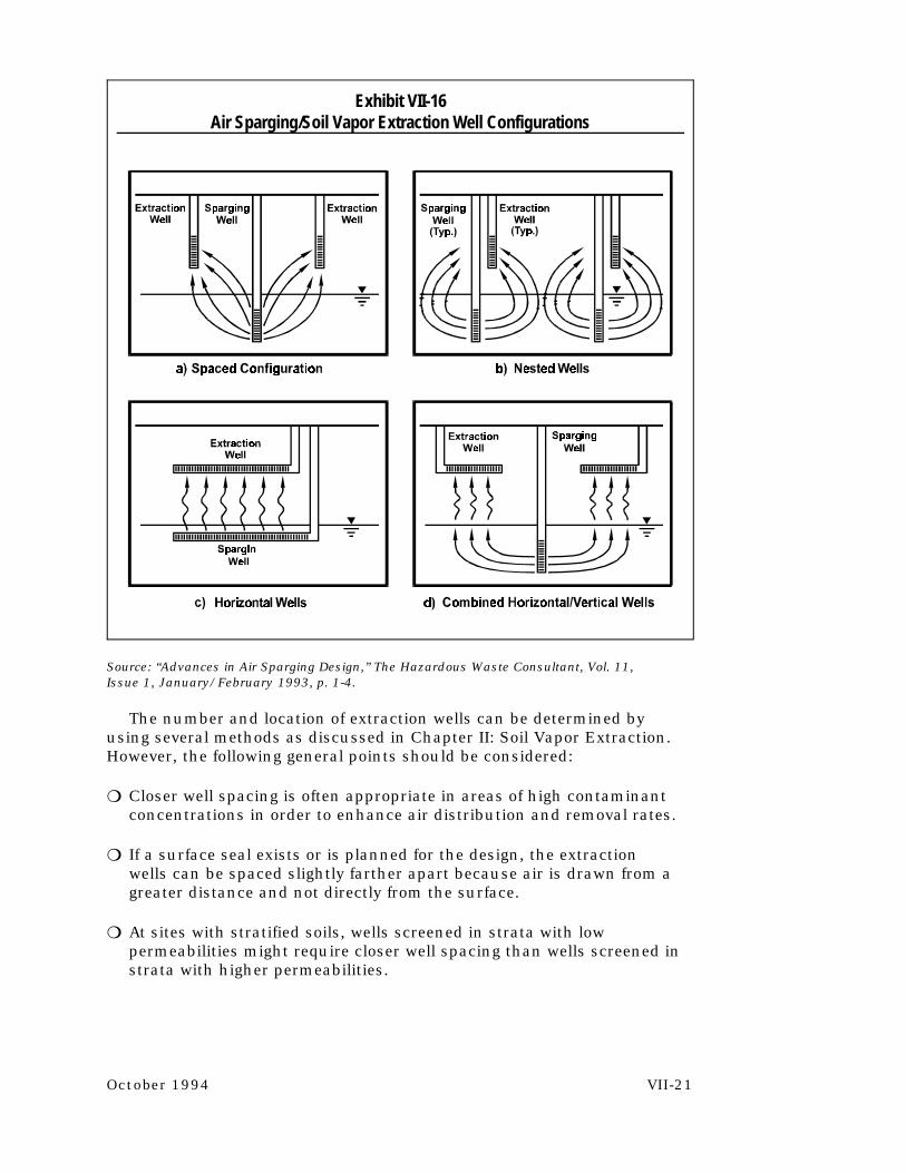
Exhibit VII-16 Air Sparging/Soil Vapor Extraction Well Configurations
Source: “Advances in Air Sparging Design,” The Hazardous Waste Consultant, Vol. 11, Issue 1, January/February 1993, p. 1-4.
The number and location of extraction wells can be determined by using several methods as discussed in Chapter II: Soil Vapor Extraction. However, the following general points should be considered:
� Closer well spacing is often appropriate in areas of high contaminant concentrations in order to enhance air distribution and removal rates.
� If a surface seal exists or is planned for the design, the extraction wells can be spaced slightly farther apart because air is drawn from a greater distance and not directly from the surface.
� At sites with stratified soils, wells screened in strata with low permeabilities might require closer well spacing than wells screened in strata with higher permeabilities.
October 1994 VII-21

Exhibit VII-17 Combined Air Sparging/SVE System Layout
Well Construction. The air sparging (injection) wells are generally constructed of 1 to 5 inch PVC or stainless steel pipe. The screened interval is normally from 1 to 3 feet and is generally set from 5 to 15 feet below the deepest extent of adsorbed contaminants. Setting the screen at a deeper interval requires higher pressures on the system but generally does not achieve higher sparge rates. Increased screened intervals do not improve system efficiency because air tends to exit at the top portion of the screen. Air sparging wells must be properly grouted to prevent short circuiting of the air. Horizontal injection wells should be designed and installed carefully to ensure that air exits from along the entire screen length. Perforated pipe, rather than well screening, is sometimes preferable. Exhibits VII-18 and VII-19 present typical vertical and horizontal air sparging well constructions, respectively.
Injection wells should be fitted with check valves to prevent potential line fouling caused by pressure in the saturated zone forcing water up the point when the system is shut down. Each air sparging well should also be equipped with a pressure gauge and flow regulator to enable adjustments in sparging air distribution. Refer to Chapter II: Soil Vapor Extraction for vapor extraction well details.
VII-22 October 1994

Exhibit VII-18 Typical Vertical Air Sparging Well Construction
Exhibit VII-19 Typical Horizontal Air Sparging Well Construction
October 1994 VII-23

Manifold Piping
Manifold piping connects the sparging wells to the air compressor. Piping can be placed either above or below grade depending on site operations, ambient temperature, and local building codes. Below-grade piping is more common and is installed in shallow utility trenches that lead from the sparging wellhead vault(s) to a central equipment location. The piping can be either manifolded in the equipment area or connected to a common compressor main that supplies the wells in series, in which case flow control valves are located at the wellhead. Piping to the well locations should be sloped toward the well so that condensate or entrained groundwater will flow back toward the well.
The pressurized air distribution system can be made of metal pipe or rubber-reinforced air hose. PVC pipe should not be connected directly to the compressor because of the high temperatures of air leaving the compressor which can diminish the integrity of the PVC. If pipe trenches are used for the distribution system, they must be sealed to prevent short circuiting of air flow.
Compressed Air Equipment
An oil-free compressor or a standard compressor equipped with downstream coalescing and particulate filters should be used to ensure that no contaminants are injected into the saturated zone. The compressor should be rated for continuous duty at the maximum expected flow rate and pressure to provide adequate flexibility during full operations.
Monitoring And Controls
The parameters typically monitored in an air sparging system include:
� Pressure (or vacuum) � Air/vapor flow rate
The equipment in an air sparging system used to monitor these parameters provides the information necessary to make appropriate system adjustments and track remedial progress. The control equipment in an air sparging system allow the flow and sparge pressure to be adjusted at each sparging well of the system, as necessary. Control equipment typically includes flow control valves/regulators. Exhibit VII-20 lists typical monitoring and control equipment for an air sparging system, where each of these pieces of equipment should be placed, and the types of equipment that are available.
VII-24 October 1994

Exhibit VII-20 Monitoring And Control Equipment
Monitoring Equipment
Flow meter
Pressure gauge
Vapor or air sparge temperature sensor
Sampling port
Control Equipment
Flow control valves/ regulators
Location In System
� At each injection and vapor extraction well head
� Manifold to blower � Stack discharge
� At each injection and vapor extraction well head or manifold branch
� Before blower (before and after filters)
� Before and after vapor treatment
� Manifold to blower � Blower or compressor
discharge (prior to vapor treatment)
� At each vapor extraction well head or manifold branch
� Manifold to blower � Blower discharge
� At each vapor extraction well head or manifold branch
� Dilution or bleed valve at manifold to blower
� At header to each sparge point
Example Of Equipment
� Pitot tube � In-line rotameter � Orifice plate � Venturi or flow tube
� Manometer � Magnehelic gauge � Vacuum gauge
� Bi-metal dial-type thermometer
� Thermocouple
� Hose barb � Septa fitting
� Ball valve � Gate valve � Dilution/ambient air bleed
valve � Gate valve � Dilution/ambient air bleed
valve
Evaluation Of Operation And Monitoring Plans
The system operation and monitoring plan should include both system startup and long-term operations. Operations and monitoring are necessary to ensure optimal system performance and to track the rate of contaminant mass removal.
October 1994 VII-25

Startup Operations
The startup phase should begin with only the SVE portion of the system (if used) as described in Chapter II. After the SVE system is adjusted, the air sparging system should be started. Startup operations should include 7 to 10 days of manifold valving adjustments to balance injection rates and optimize mass flow rates. Injection and extraction rates, pressures, depth to groundwater, hydraulic gradient, and VOC levels should be recorded hourly during initial startup until the flow is stabilized. Injection rates should then be monitored daily. Vapor concentration should also be monitored in any nearby utility lines, basements, or other subsurface confined spaces. Other monitoring of the system should be done in accordance with the SVE requirements from Chapter II.
Long-Term Operations
Long-term monitoring should consist of contaminant level measurements (in the groundwater, vapor wells, and blower exhaust), flow-balancing (including flow and pressure measurements), and vapor concentration readings. Measurements should take place at biweekly to monthly intervals for the duration of the system operational period.
Samples collected during sparging operations may give readings that show lower concentrations of dissolved contaminants than those found in the surrounding aquifer. These readings could lead to the erroneous conclusion that remediation is occurring throughout the aquifer. Therefore, contaminant concentrations should be determined shortly following system shutdown, when the subsurface environment has reached equilibrium.
Exhibit VII-21 provides a brief synopsis of system monitoring requirements.
Remedial Progress Monitoring
Monitoring the performance of the air sparging system in reducing contaminant concentrations in the saturated zone is necessary to determine if remedial progress is proceeding at a reasonable pace. A variety of methods can be used. One method includes monitoring contaminant levels in the groundwater and vapors in the monitoring wells and blower exhaust, respectively. The vapor and contaminant concentrations are then each plotted against time.
VII-26 October 1994

Exhibit VII-21 System Monitoring Recommendations
Monitoring Phase Frequency What To Monitor Where To Monitor
Startup (7-10 days) At least daily � Sparge pressure � Air sparging wellhead � Flow � Sparge and extraction � Vacuum readings (SVE) wells � Vapor concentrations (SVE) � Manifold
� Effluent stack
Long-term Biweekly to monthly � Flow (SVE) � Extraction vents (ongoing) � Vacuum readings (SVE) � Manifold
� Sparge pressure � Air sparging wellhead � Vapor concentrations (SVE) � Effluent stack
Quarterly to � Dissolved constituent � Groundwater annually concentrations monitoring wells
Remedial progress of air sparging systems typically exhibits asymptotic behavior with respect to both dissolved-phase and vapor-phase concentration reduction (Exhibit VII-22). Systems that use SVE can monitor progress through mass removal calculations. (See Chapter II: Soil Vapor Extraction for calculations.) When asymptotic behavior begins to occur, the operator should evaluate alternatives that increase the mass transfer removal rate (e.g., pulsing, or turning off the system for a period of time and then restarting it). Other more aggressive steps to further reduce constituent concentrations can include installation of additional air sparging or extraction wells.
If asymptotic behavior is persistent for periods greater than about 6 months and the concentration rebound is sufficiently small following periods of temporary system shutdown, the appropriate regulatory officials should be consulted; termination of operations may be appropriate.
October 1994 VII-27

Exhibit VII-22 Concentration Reduction And Mass Removal Behavior For Both
Air Sparging And SVE Systems
VII-28 October 1994

References
Brown, L.A. and R. Fraxedas. “Air sparging extending volatilization to contaminated aquifers.” Proceedings of the Symposium on Soil Venting, April 29-May 1, 1991, Houston, Texas, pp. 249-269. U.S. EPA, Office of Research and Development. EPA/600/R-92/174, 1992.
Johnson, R.L., P.C. Johnson, D.B. McWhorter, R.E. Hinchee, and I. Goodman. “An overview of in situ air sparging.” Ground Water Monitoring Review. Vol. 13, No. 4, pp. 127-135, 1993.
Hinchee, R.E. Air Sparging for Site Remediation. Boca Raton, FL: Lewis Publishers, 1994.
Marley, M., D.J. Hazenbronck, and M.T. Walsh. “The application of in situ air sparging as an innovative soils and groundwater remediation technology.” Ground Water Monitoring Review. Vol. 12, No. 2, pp. 137145, 1992.
Martin, L.M., R.J. Sarnelli, and M.T. Walsh. “Pilot-scale evaluation of groundwater air sparging: site-specific advantages and limitations.” Proceedings of R&D 92-National Research and Development Conference on the Control of Hazardous Materials. Greenbelt, MD: Hazardous Materials Control Research Institute, 1992.
U.S. Environmental Protection Agency. A Technology Assessment of Soil Vapor Extraction and Air Sparging. Washington, D.C.: Office of Research and Development. EPA/600/R-92/173, 1992.
October 1994 VII-29

Checklist: Can Air Sparging Be Used At This Site?
This checklist can help you to evaluate the completeness of the CAP and to identify areas that require closer scrutiny. As you go through the CAP, answer the following questions. If the answer to several questions is no, you will want to request additional information to determine if air sparging will accomplish the cleanup goals at the site.
1. Factors That Contribute To The Vapor/Dissolved Phase Partitioning Of The Constituents
Yes No
� � Is the Henry*s law constant for the contaminant greater than 100 atm?
� � Are the boiling points of the contaminant constituents less than 300EC?
� � Is the contaminant vapor pressure greater than 0.5 mm Hg?
2. Factors That Contribute To Permeability Of Soil
Yes No
2� � Is the intrinsic permeability greater than 10-9 cm ?
� � Is the soil free of impermeable layers or other conditions that would disrupt air flow?
� � Is the dissolved iron concentration at the site < 10 mg/L?
3. Evaluation Of The Air Sparging System Design
Yes No
� � Does the radius of influence (ROI) for the proposed air sparging wells fall in the range 5 to 100 feet?
� � Has the ROI been calculated for each soil type at the site?
� � Examine the sparging air flow rate. Will these flow rates provide sufficient vapor/dissolved phase partitioning of constituents to achieve cleanup in the time allotted for remediation in the CAP?
VII-30 October 1994

3. Evaluation Of The Air Sparging System Design (continued)
Yes No
� � Examine the sparging air pressure. Will the proposed pressure be sufficient to overcome the hydraulic head and capillary forces?
� � Is the number and placement of wells appropriate, given the total area to be cleaned up and the radius of influence of each well?
� � Do the proposed well screen intervals account for contaminant plume location at the site?
� � Is the proposed well configuration appropriate for the site conditions present?
� � Is the air compressor selected appropriate for the desired sparge pressure?
4. Operation And Monitoring Plans
Yes No
� � Does the CAP propose starting up the SVE system prior to starting the air sparging system?
� � Are manifold valving adjustments proposed during the first 7 to 10 days of operation?
� � Is monitoring for sparge pressure and flows, vacuum readings (for SVE), groundwater depth, vapor concentrations, dissolved oxygen levels, carbon dioxide levels, and pH proposed for the first 7 to 10 days of operation?
� � Is weekly to biweekly monitoring of groundwater pH and levels of contaminants, carbon dioxide, and dissolved oxygen proposed following startup?
� � Is weekly to biweekly monitoring of the effluent stack for levels of contaminants, oxygen, and carbon dioxide proposed following startup?
October 1994 VII-31