air sparging, an innovative technique for site remediationinfohouse.p2ric.org/ref/28/27711.pdf ·...
TRANSCRIPT
e2 AIR SPARGING, AN INNOVATIVE TECHNIQUE FOR SITE REMEDIATION Z-7 p r ,
Keith G. Angell, P.E., CHMM
Groundwater Technology, Inc. 100 River Ridge Drive Norwood, MA 02062
HAZARDOUS MATERIALS MANAGEMENT CONFERENCE HazMat South '91 October 2-4, 1991
ABSTRACT
The inefficiencies of traditional site remedial efforts have prompted development of innovative techniques such as air sparging to reduce the cost and time of remediation. Air sparging is an emerging in situ technology that enhances desorption and bioremediation of saturated soils by forcing air under pressure into the saturated zone. Since remediation of adsorbed and dissolved phased contamination oftentimes is the longest and most costly part of site cleanup, the application of air sparging in multi-phase cleanup program promotes time and cost effective remediation by addressing these difficult phases of contamination.
This paper presents a technical background and explanation of air sparging, details two case studies, outlines the results of these cases, and concludes with the application and limitations of air sparging.
INTRODUCTION
Traditionally, soil and groundwater Contamination have been treated by excavation of the contaminated soils and/or by pumping and treating the contaminated groundwater. Soil excavation is often neither a practical nor cost effective solution, and groundwater treatment often is still required following soil excavation. Groundwater pumping, while effective in containing contamination migration, is generally an unacceptably slow remediation process.
The long remediation time frame for a simple pump and treat operation is generally due to the equilibrium that is attained between the dissolved and adsorbed phases of contamination. A measure of the amount of a compound that sorbs to the soil relative to what is dissolved is given by the partition coefficient, &. The partition coefficient is the product of the organic carbon/water partition coefficient, I&, and the fraction of organic carbon in the soil, &. When I$ exceeds 1, contamination will reside principally in the soil matrix, rather than in the groundwater. Since & is in the range of 1-3% for most soils, I$ will usually exceed 1 in situations where & exceeds 50.
92


This distribution between adsorbed and dissolved contamination affects groundwater remediation in two ways. First, organic compounds that sorb to soils are retarded in their water phase transport relative to groundwater movement. This means that more water must be pumped to collect the compound that is contained in the area of contamination. The effect of pumping groundwater at a greater rate leads to the second affect. At high pumping rates, the leaching of contaminants from soil into groundwater can become transport limited, resulting in lower groundwater concentrations. This is because the contact time between the groundwater and soil is insufficient to allow enough of the compound to diffuse through the soil and into the groundwater to equilibrium. When a pumping system is turned off, contact time is increased and the groundwater concentration of the contaminant increases because the groundwater flow rate is now slower and the dissolution of contaminants is equilibrium controlled, rather than transport controlled. This results in a "rebound" effect when the pumping system is turned off.
Since natural subsurface formations are rarely homogenous and isotropic units, the interlayering of high- and low-permeability sediments often results in significant variations in local groundwater velocity (advection) within the aquifer. Virtually all groundwater flow under pumping conditions will occur through the higher permeability sediments, and contaminants are rapidly removed from these zones. In contrast, very little flow is induced in the low-permeability sediments and contaminants are released from this zone primarily through the relatively slow mechanism of diffusive transport. This diffusion process, as described by Fick's Law, involves molecular movement along a concentration gradient from areas of high contaminant concentration to areas of low contaminant concentration.
A pump-and-treat remediation system that maintains low concentrations in the high-permeability sediments provides an avenue for transport of contaminants from contaminated low-permeability sediments to high-permeability sediments and ultimately to recovery wells. Unfortunately, the physical limitations of diffusive transport result in an extremely slow rate of overall contaminant recovery under this scenario. The overall efficiency of the remediation effort is further impaired due to the fact that the majority of the total contaminant mass is likely to be present in the low-permeability sediments. Since low-permeability sediments have a surface area per unit volume that is orders of magnitude greater than the surface area per unit volume for coarser sediments, they have a capacity to adsorb a much greater quantity of contaminants. Therefore, a heterogeneous aquifer contaminated by VOCs will often have the majority of contaminants adsorbed to fine sediments that can only release contaminants slowly by diffusive transport.
Project durations are often estimated by calculating the number of pore volumes of Contaminated water that would need to be pumped at equilibrium concentrations in order to remove the total estimated contaminant mass. The assumption of equilibrium concentration is also important in that the most cost- effective application for pump-and-treat remediation systems is achieved by minimizing the volume of groundwater pumped and maximizing the concentration of contaminants in that water. This scenario would typically provide the lowest lifetime operating costs in terms of power usage and treatment costs. Unfortunately, a more common scenario for pump-and-treat remediations is to pump relatively large volumes of water with relatively low contaminant concentrations. This Is due to the effect of groundwater velocity on partitioning between adsorbed or pure phase contaminants and groundwater. Conventional pump-and-treat wellfields generally create local groundwater velocities that are considerably faster than natural flow velocities under static conditions. These faster flow velocities may not allow sufficient contact time between contaminated sediments and groundwater to reach equilibrium concentrations in the water before it is advected away from the contaminated zone. The groundwater is replaced by clean water from upgradient and the net effect is to pump relatively large volumes of groundwater at lsss than equilibrium concentrations.
9 3

Table 1 presented below lists & values for several common volatile constituents.
TABLE 1: Soil/Watec pertitioning coefficient of Selected Volatile Constituents 1
Trichloroethylene
Trans-1,l-Dichloroethylene
Naphthalene
Contaminant Partltionlna Coefficient, )c I
152.0
169.0
1,300.00
II Acetone I 1.0 II II Benzene I 97.0 I / Tetrachloroethvlene I 303.0 II
Not only do aeration systems (venting and sparging) remove VOCs directly, they also enhance degradation of VOCs. Because vacuum extraction and air sparging increase air flow through contaminated areas, these remedial techniques increase oxygen availability and thus stimulate natural biodegradation. This further increases the rate of remediation during the use of aeration techniques. Presented below are technology facts concerning these two aeration technologies -- air sparging and vapor extraction.
AIR SPARGING TECHNOLOGY
Removal of VOCs below the water table can be accomplished by sparging air under pressure through soils below the water table. This approach effectively creates a crude air stripper in the subsurface. The saturated sol column acts as the packing. Injected air flows through the water column over the packing (Figure 1). Air bubbles contact dissdved/adsorbed phase contaminants in the aquifer causing the VOCs to volatilize. The entrained organics are carried by the air bubbles into the vadose zone where they can be captured by a vapor extraction system or, where permissible, allowed to escape through the ground surface. As a bonus, the sparged air maintains high dissolved oxygen, which enhances natural biodegradation.
The stripability of the VOC contaminants by the air sparger system is roughly indicated by their Henry’s Law constant, I$,. A I$, of > lG5 atmm3/mole indicates a stripable volatile constituent. Table 2 lists the Henry’s constant for several VOCs.
9 4

Air sparging creates turbulence and increased mixing in the saturated zone, which increases the contact between groundwater and soil. When the leaching of contaminants from soil into groundwater is transport limited, this mixing results in higher transport rates and therefore higher concentrations of VOCs in the groundwater.
The key to successful air sparging operation is attaining good contact between the injected air and contaminated soil and groundwater. Below the water table, the air bubbles need to travel vertically through the aquifer in order to strip the VOC contaminant(s). A permeability differential (i.e., clay barrier) above the zone of air injection may severely reduce the effectiveness of air sparging, so such barriers should be identified during a pilot test study.
There are two potential concerns with the use of air sparging. The first is the spread of dissolved contamination. The second is the acceleration of vapor phase transport and the subsequent accumulation of vapors in buildings.
If the geology constricts vertical air flow, then sparging can push the dissolved Contamination concentrically from the injection point. This has been a significant problem in the use of air sparging in Germany’. As a result, in certain low permeable/heterogeneous formations sparging requires a groundwater recovery system to prevent the spread of dissolved contamination.
Since air sparging increases pressure in the vadose zone, any exhausted vapors can be drawn into building basements. Basements are generally low pressure areas, and this can lead to preferential vapor migration and accumulation in basements. As a result, in areas with potential vapor receptors, air sparging should be evaluated with a concurrent vent system.
Air Sparging vs. Pump and Treat When comparing in situ groundwater aeration programs with pump-and-treat alternatives, it is evident that air injection is subject to many of the same physical flow processes described above. However, there are several aspects of air flow in the subsurface and of the physical construction details for an air injection system that make it a promising technology with clear advantages over a conventional pump- and-treat approach. These advantages include:
Increased volumetric flow rate for air vs. water, due to higher permeability of soil to air. Simple, inexpensive installation of air injection points vs. costly installation of groundwater recovery wells. Increased mass transfer characteristics for contaminant removal by air rather than water.
(1) (2)
(3)
An increased volumetric flow rate provides an advantage for heterogeneous formations where diffusive transport from low-permeability sediments may be an issue. In this environment, the physical movement of air will occur preferentially through high-permeability sediments in much the same route that water
9 5

would travel. However, the greater volumetric flow rate for air ensures that contaminant concentrations in the air remain low, thus maximizing the concentration gradient that drives movement of contaminants out of the low-permeability zones. This low concentration in the air could be an additional cost factor for systems in locales that require off-gas treatment prior to discharge, however it represents a distinct advantage for enhancing the rate of contaminant mass removal from the subsurface under diffusion- controlled conditions.
Air Sparging and Vacuum Extraction Above the water table, VOCs can be removed by inducing air flow through areas of contamination by application of a vacuum. The air flow volatilizes and removes VOCs and supplies oxygen to support biodegradation. Nutrients, if needed, can be added periodically by percolation into the vent tubes. As long as the air flow contacts the contaminated soils, the system is effective. Proper air flow is ensured by proper spacing of vapor extraction points, and by locating the horizon of contamination and screening the vapor extraction well(s) accordingly.
The ventability of a compound is related to its vapor pressure. The vapor pressure of a compound is the pressure of its vapor in equilibrium with its pure liquid or sdid phase. The temperature at which the vapor pressure of a liquid is equal to atmospheric pressure is the boiling point of that compound. Vapor pressure increases with temperature. As a rule of thumb, a contaminant can be effectively removed by vacuum extraction only when its vapor pressure exceeds 1 .Omm Hg.
For a fixed flow rate of venting air, the maximum rate at which a contaminant can be extracted is found by assuming the partial pressure of the contaminant in the vented gas is equal to the vapor pressure of the contaminant. The molar density of the contaminant in the gas phase is equal to its partial pressure, assuming ideal behavior. Table 3 gives the vapor pressure at 4OOF and maximum extraction rates of some common VOCs.
Maximum - vapor extractablllty-* Vapor Pressure ' Campound
@ 4cpF (mm Hgf I b / l d Ib/day @ 100 SCFM I
Benzene 28 7.9 1134
Toluene 9 3.0 430
II Xvlenes I 3.0 I 1.1 I ~
165 - Methylene Chloride 198.9 59.9 8622
Chloroform 77.0 33.2 4782
1,l DCA 89.0 31.7 4564
l,l,l TCA 4.6 21.9 3154
TCE 28 13.1 1891
PERC 7.5 4.49 646
Chlorobenzene 3.8 1.5 221
Naphthalene 0.1 0.05 7
* Assumes continuous vapor saturation
9 6

Actual extraction rates will generally be less than the calculated maximum for two reasons. First, the contact time between the venting air and the contaminated soil may be insufficient to allow enough contamination to diffuse through the soil and into the air stream to establish the equilibrium vapor pressure (especially if significant channeling has occurred). Second, soil is generally not uniformly contaminated, and so not all of the vented air will have passed through a contaminated zone. Thus, even if air passing through a contaminated zone were saturated with VOCs, it would be diluted by clean air which had passed only through uncontaminated soil. Proper design of a vacuum extraction system can maximize air/soil contact in the contaminated zone and so maximize extraction efficiency.
Principles of Design The principles of design for vapor extraction and air sparging systems are significant and complex. critical elements of each system are summarized below.
Two factors are critical to the effective design and operation of soil vapor extraction systems. The first factor is the extraction system itself which Includes the number, spacing and location of extraction wells, manifold layout, and the size and type of blowers. A properly designed extraction system operates with minimal adjustment. A poorly designed system requires the repeated installation of additional wells, piping, and Mowers.
The second factor is the vapor abatement system. Regulatory agencies often require extracted vapors to be treated. Carbon is generally easy and cheap to install and permit. However, with high VOC levels carbon can be expensive to use. Thermal systems, on the other hand, require higher capital expenditures, take time to permit, but are relatively inexpensive to operate. Determining when a thermal system is justified and which type to use is an Important part of design.
The maximum venting efficiency is attained in a soil vent system when:
1) 2) 3)
The induced air flow directly contacts the contaminated soil; The radius of influence of the vent well(s) matches the area of contamination; and, The correct size vacuum Mower is chosen based on site specific soil permeability conditions such as moisture content, texture, and mineralogy.
The information required to satisfy these conditions is best obtained by conducting a soil vent feasibility study. The key parameters that must be determined in a soil vent feasibility study are: the location and concentration of the contaminant, the permeabiliiy of the various soil layers, and-the ability to induce air flow preferentially through the contaminated area. Once the VOC concentration and expected flow rate for the air stream have been determined, the proper vacuum pump and emission control device can be selected. During the feasibility test, a vacuum is drawn on a well screened in the unsaturated zone, and the vacuum response as a function of time and distance is measured in other wells at the site. The pumping Is allowed to reach steady state whereupon the vacuum and flow rate at the extraction point are recorded, and the induced vacuum at the monitoring points located at various distances from the pumping well is measured with a MagnehelicTM gauge or manometer.
The following information is needed for effective air sparge system design:
1) 2) 3)
4)
The location of potential groundwater and vapor receptors; The geological conditions of the site - permeability, lithology, heterogeneity; The contaminant mass distribution within the area to be treated in both -dl and aroundwater. This distribution should be "superimposed" on the lithology of the site; and, The radius of influence of the sparge well@) at various flow rate/pressure.
As with Vacuum earaction, the best design of a sparge system requires a field test. The following parameters should be monitored during the field test:
9 7

Pressure vs. distances. This is an indication of radius. VOC concentrations in groundwater. This is an indication of what is being removed and areas being impacted, it should be done before, during (with and without the system running) and after test. CQ and 4 levels in soil vapor. This is an indication of biological activity. Again, it needs to be done before, during and after test for petroleum contamination sites, under static as well as pumping conditions. Dissolved oxygen levels in water. This is a good indicator of effect - may be slower to see than air flow. Need to have good base line before test to determine changes. Need background as well. Water levels before and during test. Air flow will cause some mounding. This needs to be done before test to determine background.
The ease and relatively low expense of installing small-diameter air injection points allows considerable flexibility in the design and construction of a remediation system. The ability to install a dense grid of injection points without major site disruption or expense means that many of the problems associated with stagnation zones in pumping wellfields may be avoided simply by having complete coverage of the contaminated zone with injection points. The construction of the air injection points also allows a fairly precise targeting of the aeration effect. The screened zone for these points is typically very short, providing essentially a single point of aeration. If site investigation activities have identified zones or layers of either high contamination or aquifer heterogeneity, injection points may be dedicated to concentrate remediation activities on a specific zone. This ability to tightly focus remediation efforts alleviates the problem of aquifer heterogeneities influencing flow patterns in a pump-and-treat system.
Detailed below are two case studies for sparging systems that have operated over the past year. The first case Is presented in great detail to indicate the type of assessment and evaluation needed to properly design remedial systems. The second case study is more concise for ease of reading.
CASE STUDY #I
The first case study site is the former location of a dry cleaning facility in New Castle County, Delaware. Soil and groundwater contamination resulted from leaking underground storage tanks which were located in the north-northwestern part of the property. The tanks, which have been removed, were used to store dry cleaning sdvents. Primary groundwater contaminants have been identified as perchloroethylene (PCE), trichloroethylene (TCE), dichloroethylene (DCE) and some total petroleum hydrocarbons (TPH) related to heating oil. PCE is the primary contaminant of concern. TCE and DCE are present primarily due to bidogically mediated reductive dehalogenation.
PCE. TCE, DCE and total petroleum hydrocarbon constituents were detected in groundwater samples cdlected from shallow monitoring wells at various locations on the property. It should be noted that these chlorinated sdvents, in their pure state, have densities greater than water (solubilities range from 150 milligrams PCE to 1,100 milligrams TCE per liter in water). However, concentrations of these constituents detected at the property are well below their respective saturation limits and also show a decreasing concentration with depth. This supports a conclusion that the groundwater impact is localized to the upper portion of the shallow aquifer, and that deeper aquifer impacts related to the density of the sdvents are not expected.
Site lnformatlon
The subsurface environment at the property generally consists of miscellaneous occurrences of fill material sporadically overlying a continuous sheet of naturally occurring Quaternary sediments. Within the southern geographical portion of the property, the Quaternary sediments rest unconformably on top of the sediments of the Potomac Formation which in turn overlie the basement complex consisting of a
9 8

volcanic intrusive rock, probably granodiorite. The static water level data was used to infer groundwater flow direction at the property. These data include depth to water, elevational datum for each monitoring well, as well as water level elevations relative to mean sea level.
Groundwater contour maps indicate the direction of groundwater gradient within the shallow water- bearing zones appears to trend northwest (NW) to southeast (SE), under an average hydraulic gradient of 0.021 ft/ft across the property. The geology observed during drilling activity indicates that the saturated quaternary sediments are relatively homogeneous across the property. This observation of homogeneous sediment is confirmed by the fact that the gradient does not vary appreciably across the property (ranging from 0.0015 ft/ft between MW-IS - MW-2S and 0.0026 ft/ft between MW-PS - MWJS). Other data show that deeper groundwater at the property trends northeast (NE) to southwest (SW) under an average hydraulic gradient of approximately 0.001 ft/ft. Groundwater flow within this deeper zone depends on the degree and extent of localized weathering of the granodiorite, which may provide preferential flow pathways within the deeper water-bearing zone.
Site-specific geologic conditions are such that a natural barrier (clays of the Potomac Formation) exists which locally minimizes the potential for vertical downward migration of dissolved-phase total petroleum hydrocarbon and chlorinated volatile organic compounds (VOCs) present in the shallow water-bearing zone into deeper water bearing units. This is supported by water quality data obtained from the deep and shallow well nests (MW-lS/D, MW-SS/D and MW3S/D) located on the property. The shallow wells are highly contaminated, while the deep wells are relatively clean.
Pilot Test Results Installation of an air sparge/vent fASV) system requires proper design of the separate components (the vent system and the sparge system), as well as a balancing of the two components. There are many factors which must be considered in designing a soil vapor extraction/air sparge system. These factors include a determination of the following:
1) The radius of influence of the vacuum extraction system; 2) The radius of influence of the air sparging system; and, 3) The presence of any barriers present in the subsurface which may significantly affect air flow.
Evidence of vapor barriers, or the lack thereof, is gathered during site activities including the drilling of monitoring wells, vent and sparge test wells and vapor probe locations. The technical information required for determination of the vent and sparge point spacing and equipment specifications was obtained by performing a series of field pilot tests. The test configuration consisted of a single vacuum extraction well, a single air sparger well point, and five nested monitoring probes sets.
The field test was run in three parts. First, the vacuum extraction system was tested with the air sparger system turned off. Second, the air sparge system was tested with the vacuum extraction system turned off. Finally, both systems were tested simultaneously. A description of testing procedures and results is given below.
The vent tests were conducted at well vacuum levels of 5" and 10" of water column using a 1 HP ORS soil vent system blower including a particulate filter, vacuum gauges and an ambient air intake valve to contrd flow/vacuum. The blower was powered by a portable generator. Vacuum induced in the formation as a result of suction on vapor extraction test point was measured in a group of nested probe sets located at various distances from the point.
Vacuum readings generally decrease exponentially with distance. Therefore to calculate an effective radius of influence, the log of the vacuum is plotted versus distance. This plot results in a straight line which may be extrapolated to low vacuum values to obtain an effective radius of influence. For the purpose of presenting the effective radius of influence, vacuum influence was considered present at an induced vacuum level of 0.10 inches of water column or greater.
9 9

In a relatively homogeneous site, the vacuum developed in the soil is generally radial from the extraction point. However, where there is structural heterogeneity the vacuum response observed may reflect a structural control. This appears to be the case at this site. Pilot test results indicated an apparent increase in vacuum levels, preferentially oriented from NW to SE, generally in the direction of shallow groundwater flow.
70 psi
Exclude ALL Probe 5
I
The vent test results were evaluated as discussed above, by plotting the log of the vacuum versus distance. When plotted, there is a higher correlation observed when the results are grouped by orientation rather than when used without any groupings. Since there was little variation in readings with probe depth, the results were analyzed for the deepest probe only. The calculations showed the radius of influence NE to SW (in the general direction of shallow groundwater flow) may be as little as one-half the radius of influence NW to SE (perpendicular to the general direction of shallow groundwater flow). At 5 inches of water column applied vacuum, the minimum area of influence calculated represents an ellipse with radii of 54 and 34 feet; the maximum area represents a circle with a 52 foot radius. At 10 inches of water column vacuum, the minimum area of influence calculated represents an etlipse with radii of 132 and 64 feet; the maximum area represents a 133 foot radius circle.
The sparge well (AS-1) was installed to a depth of 33 feet below grade and screened from 30 to 33 feet. Sparge tests were performed by injecting air into the sparge test point at 10, 15 and 20 psi; the flow rates which correspond to these pressure levels are 16, 24 and 37 CFM, respectively. The resulting pressure and VOC levels were measured in the five vapor probe nests which were previously utilized for the vent tests. Sparging influence was considered present at an induced pressure level of 0.01 inches of water cdumn. As with the vent test results, there was little difference between shallow and deep probe pressure values.
The sparge test data was analyzed by plotting the log of pressure versus distance. The results of these calculations are tabulated in Table 4. Because the response in Probe 5 was much lower than expected, radii of influence were calculated with and without its inclusion at each pressure level. The radius of influence (ROI) obtained by excluding Probe 5 was used in further discussion of results and final design of the system.
15 psi 20 Pa Exclude Exclude
AU Probe 5 Au. Probe 5 I I
11 Effective ROI.ft I 78 I 72 I 124 I 76 I 225 1 177 11 II I1
11 Correlation I 69.0% I 81.5% I 80.1% I 95.6% I 53.0% I 95.7% 11 The sparge results appeared to be radial and do not indicate any directional orientation/correlation. The change In VOC concentrations during the sparge tests was dramatic. In most probes the VOC levels, as indicated by OVA readings, Increased significantly with sparging; the OVA responses are presented in Table 5. A conclusion drawn from these results is that the soil/groundwater contamination below the water table is being volatilized by the sparge point.
100

2D 51 150 280 lo00 > lo00
4s 9 64 400 > loo0 > lo00
4D 9 780 > lo00 > lo00 830 - During the sparge tests a 70 to 225 foot radius of influence (at 0.01 inches of water column pressure) was developed. Substantial increases in VOC levels (as indicated by the OVA) were measured from the probes in the vadose zone. This test demonstrated the feasibility of sparging for VOC treatment at and below the water table.
Monitoring Well Number
During the sparging process, air injected below the water table displaces water from the pore spaces in the soil. This may cause a mounding of the water table in the vicinity of an injection point. To verify this mounding, water levels were measured in the monitoring wells during the 20 psi sparge test. Increasing water levels within the monitoring wells indicated that air was moving through the subsurface and that sparge test point was in communication with the monitoring wells. These results are shown in Table 6 presented below.
Depth to Water Distance From AS-1
static Levels Q2OPd Change In DTW
1 Shallow (S)
1 Deep (D)
2s
2D
4s
115 13.90 12.77 1.13
115 14.32 13.01 .51
20 13.92 13.24 .68
28 13.60 10.22 3.38
86 13.05 12.22 .a3
101

The fact that probe OVA readings were generally higher during the combined sparge/vent test then during the vent only test indicates that the combined system is effective in removing VOCs at, above, and below the water table.
As indicated by the above table, only probes 4 and 5 (shallow and deep), which were close to the sparge test point (AS-1) and most distant from the vent test point (VP-l), exhibited a positive pressure during the combined test. The following discussion provides an explanation for these values and describes their relationship to the fate of sparged air at the site.
Shallow probes (Probe X3 shallow and Probe #4 shallow), which lie between the sparge and vent test points, (VP-1 and AS-1) exhibited 3 to 5 times greater vacuum (or less pressure) than the corresponding deep probes at the same location during the combined test. Although Probe Nest #4 exhibited a deep probe pressure level of 0.50 inches of water column, the shallow probe pressure was less than 0.10 inches of water cdumn. This indicates that residual positive pressure created by sparged air, as it bubbles through the saturated zone, is rapldiy reduced by venting operations as the air moves upward through !he vadose zone.
The test results indicate that a combined air sparge/vent system can be utilized to effectively remove VOC constituents which currently exist in the subsurface at the subject proporty. Both the hydrogedogic study results and pilot study results indicate that subsurface conditions are compatible with implementation and operation of an air sparge/soil vent system at the site.
In summary, the results of the pilot tests indicated the following:
Significant air flow can be induced through the vadose zone, capillary fringe and shallow saturated zone facilitating the effective removal of PCE, TCE, DCE and other volatile organics currently in the subsurface at the property.
SE (parallel to the direction of shallow groundwater flow) rather than perpendicular to it. The radius of influence (0.10 inches of water column vacuum) of the vent system was calculated to be approximately 132 feet NW to SE, and as little as 64 feet NE to SW at a vent test vacuum level of 10 inches of water column.
Air flow in the vadose zone may be directional since there is a greater apparent influence NW to
m Air flow in the saturated zone appears to be radial. The radius of influence (0.01 inches of water cdumn pressure) of the air sparge system was calculated to be approximately 72 feet at an Injection pressure of 10 psi.
1 0 2
m Sparged air can be effectively captured by a vent system co-located on the property. This can be accomplished by operating the vent system at a vacuum level/flow rate sufficient to influence the sparged air and capture off gases generated by the sparge system.
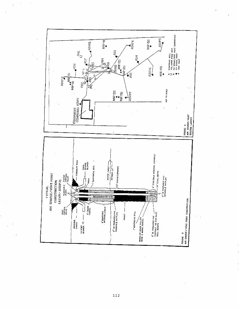
System Design Based on data obtained during the pilot tests a pattern of additional vent and sparge points was developed to provide overlapping influence (negative net pressure) and favorable site coverage for the treatment system. Strategically placed additional probe nests were also added to monitor system performance. A complete list of treatment and monitoring points installed at the site is specified below.
7 Combination vapor extraction/air sparge points (ASPPI ASpP7); to be installed (see Figure 3 for typical schematic construction diagram).
m 1 Vapor extraction only point (VP1); existing.
7 Sparge only points (ASlAS7).
8 Vapor monitoring probe nests (PR1-PR8).
m 7 Shallow monitoring wells (MWIS-MW7S).
3 deep monitoring wells (MWlD-MW3D; see Figure 4 for system layout.
Results of the vent test conducted at 10 inches of water column vacuum indicated that the area influenced to 0.1 inches of water column or greater by a single vent point was a 114’ by 64’ ellipse. This occurred at a flow rate of 68 CFM. In order to provide assurance that adequate vacuum would be induced across the site, the pattern of vent locations necessary for full coverage was determined by assuming a minimum area of influence for each vent point as a 100’ by 50’ ellipse with the long axis oriented NW to SE, roughly parallel to the direction of shallow groundwater flow.
A total of eight vent locations (1 vent only and 7 co-located sparge/vent points) operating at a minimum vacuum level of 10 inches of water column were specified to provide this coverage. The 7 outer vent points are co-located with sparge points and form a rough ellipse oriented with the long axis NW to SE, surrounding the former tank field area and extending to the property perimeter. The other point (test point VP-1) is located near or within the former tank field area.
Venting was designed to be accomplished using a 15 Hp, Oil Recovery Systems soil vent system having a capacity of 500 CFM at 40 inches of water column vacuum. Influent vacuum/flow rate is controlled with an ambient air intake valve. A liquid knockout tank, particulate filter and muffler will be placed on the influent line to eliminate or reduce water generated during system operation, solids and noise respectively. An effluent muffler was specified to further reduce noise levels to meet the City’s zoning regulations. Two 1800 pound granular activated carbon (GAC) units were specified to be used in series on the vent effluent to remove contaminants from the vent air prior to discharge. These units are capable of accepting air flow rates in excess of 500 CFM.
The sparge test conducted at 10 psi indicated that the radius of the circular area influenced to a pressure level of 0.01 inches of water column or greater by a single air sparge point was 72 feet. This occurred at a flow rate of approximately 16 CFM as measured during the combined sparge/vent test. In order to ensure favorable site coverage, a 50 foot radius of influence wa assumed in designing the pattern of points to be utilized for the final system. A total of 14 sparge locations (7 co-located sparge/vent points and 7 air sparge only points), operating at a pressure of 10 inches of water column, were specified to provide this coverage. The 7 outer co-located sparge points form a rough ellipse surrounding the former tank field area and extending to ?he property perimeter. The 7 inner most sparge only points were specified to complete coverage and provide concentrated treatment within the former tank field area where contaminant levels are highest.
103
Operation of fourteen sparge points at 16 CFM each results in an expected total flow rate of 225 CFM which was used as the final design basis. The vent system should be able to easily capture the sparged air. This sparge system design flow rate is roughly one half of the vent system design flow rate of 500 CFM.
The sparge air will be provided by a 20 Hp rotary lobe type blower capable of delivering 270 CFM at 10 psi. As with the vent system, a particulate filter is provided on the inlet to protect the moving parts of the unit. System pressure is controlled with a valve on the ambient air discharge line placed on the pressure side of the sparge blower. Noise reduction was achieved with mufflers on the inlet, outlet and ambient discharge lines of the system. The air sparge blower was also furnished with an overpressure relief valve set to open at 15 psi.
Results In the first phase of remediation, the vent system was initiated. Total flow from the eight vent wells was approximately 450 CFM at a vacuum of 25-30 inches of water column. The vacuum distribution after 1 1 days of operation is pictured in Figure 5. As can be seen, the highest vacuum levels were obtained in the area directly east of the equipment compound. This is the area of the former tank pit. Vacuum levels are lower to the south and to the east. The vacuum influence developed covers the entire site indicating that vapors can be retrieved from beyond as well as within the site boundary. Vent only operations were conducted for about 1 month before the commencement of sparging.
The vent system achieved a negative pressure throughout the site with the highest vacuum being attained in or adjacent to the source area(s). The operation of the vent system did not impact the basic hydrogeology of the site.
In phase two of the remedial program, sparging was implemented in a two staged process. First, the combined vent/sparge points (ASVP1-7) were utilized. Second, the centrally located sparge only point (AS-1) was added and finally all other sparge points were added. As expected, sparge system operations had some impact on both the vacuum distribution across the site and hydrogeology.
After two weeks of sparging at an injection pressure of 10 psi, the vacuum levels measured in the 8 monitoring probe nests were reduced relative to vent-only operation. When the difference in probe vacuum response between vent only operation and vent/sparge operation is plotted, one can see the influence of the sparge system more clearly. As shown in Figure 6, the sparge system’s greatest impact is near the interior of the site. The net reduction in vacuum is greatest in this area. The impact of the sparge system decreases to the southeast.
This northwest to southeast orientation of the observed change in vacuum response is paralleled by the water table contours measured when the sparge system is operating. There is an apparent mounding of the water table across the site, oriented along the northwest southeast axis. The mounding appears greatest downgradient of the source area which should serve to minimize the movement of contaminated water from the source area. The impact of air sparging on the water table was also dramatically seen by taking water table measurements fiieen minutes after the sparge system was shut off. The water table collapsed as shown in Figure 21 as the air exited the water.
Upon start-up of the vent system, OVA readings reached as high as 1,000 units. Within one day the concentration had dropped to 250 units. As shown In Figure 7, levels continued to decrease over time though not as rapidly as with the initial drop. The first day concentration drop (from 1000 to 250 OVA units) is attributed to the rapid evacuation of soil pore space vapors which have achieved equilibrium with contaminated soils in the surrounding area. The ensuing slower decrease in concentration is the result of volatilization of contamination absorbed to soils.
After about one month of operation, the vent system VOC influent concentration had dropped to c 10 units. At this point, the sparge system was started beginning with the outer ring of sparge locations as described in Section 1 .O. The VOC levels rose in response to the sparge system from < 10 OVA units to
104

-60-70 OVA units and remained at an elevated level for several months. This is an indication of removal of VOCs below the water table. During start-up, tedlar bag samples were taken of the vent effluent and analyzed in the laboratory. Only PCE and TCE were found in any of the samples; PCE was the major constituent.
MW-1s
MW-1D
MW-2S
W - 2 D
The tedlar bag sample results were also graphed versus time. As was seen with the OVA results, the concentrations of PCE and TCE dropped during the vent start-up and rose again with the initiation of the sparge system. These results indicate that the combined system is effective in removing PCE and TCE from soils and groundwater.
2,108 3.5 4.9
14 1.9 BDL
41,000 290 897
BDL BDL 1 5
Based on the tedlar bag sample results, a cumulative mass removal was calculated for the site. As shown in Figure 8, in the first six weeks of operation, approximately 900 pounds of PCE and TCE were removed from the site. These results reflect removal of the bulk of the adsorbed phase unsaturated zone contamination. The increased VOC levels after sparge start-up indicated that the sparge system had initiated removal of contaminants contained In the saturated soils and groundwater.
Two sets of groundwater results were taken after 54 and 125 days of sparging operation. As can be seen in Table 8, there has been substantial and dramatic changes. The net reduction is greater than 98% overall. The 125 day groundwater samples were taken one week after the system shut down to allow groundwater to re-equilibrate.
MW4S
MW-GS
Mw-7s
~~
4,328 444 240
166 5 BDL
134 31 15
1 0 5

VOC contamination both above and below the water table has been effectively treated by the use of a combined air sparging - soil venting system. In a relatively short period of time (125 days) groundwater levels have been reduced by over 98%.
The system has been operated without active groundwater pumping. The mounding created by the air sparge system was designed to prevent off-site groundwater migration. This system has been effective as there has been no downgradient increase in VOCs. In fact, VOC levels in the downgradient off-site well have significantly decreased during the treatment. Over 1000 pounds of PCE and TCE have been removed by the system. This material has been effectively captured and treated by an activated carbon system resulting in no fugitive vapor losses.
CASESTUDY#2
Site Information The second site chosen for evaluation of in situ groundwater aeration was a former gasoline service station. Aromatic petroleum hydrocarbons were present in the groundwater at concentrations ranging from 6 to 24 parts per million (ppm), and the site hydrogeology had been documented through previous investigations. Groundwater beneath the site is present in a shallow aquifer of limited saturated thickness at a depth of approximately 8 feet to 13 feet below surface grade. The water-bearing sediments are composed of uniform medium to fine sand, and are underlaid by a fine sand and silt aquitard at a depth of 13 feet below grade. The limited extent of the water-bearing zone would also limit the extraction rate of groundwater by conventional pumping methods, and thus presented a good opportunity to examine the performance of an in situ aeration system. Operation of the groundwater aeration system was evaluated to determine its efficiency in removing the aromatic hydrocarbons from this shallow groundwater zone.
System Design A total of eight air injection points were Installed at the site in two phases. Three air injection points were initially installed on July 30, 1989 as part of a pilot study. The points were centrally located within the dissolved-phase hydrocarbon plume. Groundwater samples were subsequently obtained and analyzed for dissolved hydrocarbons in order to evaluate the system's effectiveness. After receiving favorable results from the initial installation, f i e additional air injection points were installed on June 6, 1990.
All of the points were installed using a truck-mounted hollow stem auger drill rig. Boreholes were extended through a medium to fine sand aquifer to the top of a fine sand and silt aquitard identified at approximately 13 feet below surface grade across the site. Injection points were constructed of 2.5-feet long 1.5-inch diameter stainless steel wdl points fitted to either I-Inch diameter schedule 80 PVC or galvanized steel pipe. The pipe extends from the top of the well screen to manifold piping installed at approximately f i e feet below grade. Injection points installed during the second phase of work were constructed with galvanized steel pipe to provide the option of heating injected air. The borehole annulus surrounding the screened portions of each injection point was backfilled with clean, graded silica sand to approximately six inches above the screened section. Approximately three feet of bentonite-cement grout was placed above the sand pack and the remaining annulus was filled with clean, native backfill.
Subsurface manifold piping connects each of the eight air injection points to an air compressor installed in the vacant service station. The compressor is run on a cyclical schedule with a continuous operating period of eight hours per day. The 16-hour period when air is not being injected allows for re- establishment of the natural groundwater flow patterns through the treatment area. This prevents the aerated area from creating a permanent barrier to groundwater flow, and allows for transport of dissolved contaminants from areas that may not be directly influenced by the air injection points into the treatment area for removal during the next injection cycle.
1 0 6

Each of the areas equipped with air injection points has also been provided with soil ventilation/vacuum extraction collection points. These points installed in the vadose zone provide a method for controlling VOC-laden vapors rising from the water table. The collection points are manifolded to two regenerative blowers that provide a total air flow of approximately 200 cfm at 20-30 inches Y O vacuum. The blowers discharge to atmosphere through an exhaust stack that disperses the vapors above the nearby building. Depending on location, this type of discharge might require off-gas control in more populous areas. A schematic diagram of the system installation is depicted in Figure 9.
Results The area of influence for the air injection points was evaluated by measuring dissolved oxygen (DO) levels in groundwater at all on-site monitoring wells. A summary of DO concentrations for two separate monitoring dates is presented in Table 1. Averaged concentrations from the two sampling dates have been contoured on Figure 10. The results Indicate up to a three-fold increase in DO concentrations occurring in wells located in the vicinity of air injection points in comparison to average background levels. Based on the available data, the average radius of direct influence for each injection point ranges between 10 and 15 feet. Dissolved oxygen levels in wells located further than 20 feet from any Injection point are not elevated above background levels.
Groundwater samples were also obtained from site monitoring wells and analyzed for dissolved hydrocarbon compounds including benzene, toluene, ethylbenzene and total xylenes (BTEX). The laboratory results for eight different sample dates, expressed as total dissolved BTEX, are summarihed in Table 9.
The data indicates a rapid decrease in dissolved BTEX concentrations by up to three orders of magnitude in wells located within ten to 15 feet of injection points. Other wells located at distances greater than 20 feet from any injection point do not show any apparent trend toward decreased hydrocarbon concentrations, and in some cases may exhibf a short-term increase in concentrations.
Monitoring of VOC concentrations in the soil ventilation system (SVS) indicate that the contaminant reduction observed in the groundwater is primarily due to transfer of the contaminants to the vapor
1 0 7
phase. VOC concentrations increased in the SVS vapor discharge by as much as three-fold during operation of an aeration system. This demonstrates that the contaminant mass lost from the groundwater near monitoring wells is actually being removed from the subsurface environment entirely.
The influence of air injection on hydraulic processes within the aquifer is evident when examining the effect upon the apparent water table surface under operating and non-operating conditions. Groundwater contour maps for these two conditions are presented in Figures 11 and 12. During system operation local water table mounding in excess of one foot has been measured centered around injection points. This mound is composed of a mixture of water and air and thus does not match the traditional definition of a water table or carry the full hydraulic implications of a true groundwater mound of the same magnitude. It does, however, have a definite impact on groundwater flow patterns, as can be seen in the second contour map of the groundwater surface observed several hours after deactivating the air injection system. Since the air had been displacing groundwater during the period of operation, and the air is able to degas from the aquifer considerably faster than water can flow in after system shutdown, the net effect is a depression in the groundwater table immediately after shutdown. This depression persists until groundwater is able to flow back into the area and natural steady-state conditions are re-established.
The distribution of both DO and Total BTEX concentrations observed during operation of this system indicate that the air injection points are achieving a lateral influence of at least 10-15 feet at this site. This lateral influence is a site-specific property that will vary with the hydrogeologic setting. The application of in situ groundwater aeration to a variety of different hydrogeologic settings has not been fully explored, but it is presumed that placement of air injection points at the bottom of a thicker saturated zone would result in greater lateral influence away from the injection point as the air bubbles rise and fan out through the formation.
Factors such as sedimentology and stratigraphy are clearly important variables in the performance of an aeration system. It is possible that the presence of very fine sand and silt laminae within the predominantly sand aquifer at this site aided in directing gas bubbles laterally along stratigraphic contacts; thus, prolonging their presence in the saturated zone and increasing the potential for contaminant diffusion to the air bubbles. Although these micro-variations in the soil fabric can be helpful in the contaminant removal process, they also point out a potential danger in the application of in situ aeration. If a more substantial layer of low-permeability sediments existed between the air injection points and the SVS collection points, the movement of vapors upward could be blocked and significant lateral movement could occur. This could have the drawback of transporting contaminants to previously clean areas or possiMy impacting nearby structures with vapors. This scenario reinforces the need to perform the necessary investigative work and have a complete characterization of subsurface conditions prior to designing a remediation system.
The phenomena of mounding and depressing the water table can be incorporated into the air injection system design. There appear to be advantages to cycling the system so as to produce a depression into which previously untreated groundwater can migrate. However, given the amount of subsurface agitation and the mounding effects, the potential for dispersion of the contaminant plume must also be considered. In many situations, the application of in situ aeration would have to be considered a companion technology to groundwater pumping designed to provide hydraulic control of contaminant transport away from the aerated zone.
In summary, the results of this case study Indicate that the application of in situ groundwater aeration is a viable technology to accelerate the mass removal rate of volatile organics from groundwater and saturated sediments. For sites where off-gas control is not required, the relatively low cost of installation and operation makes in situ aeration an attractive cost-effective alternative. Provided that the limitations of the technology are taken into account during the design process, in situ groundwater aeration provides an additional viable remediation technique to be considered during feasibility studies, and may provide significant advantages in mass removal performance at some sites.
108

CONCLUSIONS
While sparging is an exciting and useful technology, it is far from universally applicable. For sparging to be considered, the sitemust exhibit all of the five following characteristics:
1) Biodegradable or Strippablepentable Contaminants - Those contaminants which are not biodegraded are removed physically during sparging. This involves transport between soil, groundwater, and sparged air, so contaminants must be mobile in and between all phases. Contaminants must have a dimensionless Henry’s Law constant >0.01, vapor pressure >0.1 mm Hg, and partition coefficient (16,) < 1,000 to be physically removable by sparging (most light hydrocarbons and chlorinated solvents satisfy these conditions).
Contamination Extending into Saturated Zone - Sparging is unnecessary when only the vadose zone is contaminated.
2)
3)
4)
Moderate to High Saturated Soil Permeability - In order for sparged air to penetrate the soil matrix, hydraulic conductivity must be >la5 cm/sec (silty sand or better).
Homogenous Saturated Zone - Vertical movement of sparged air can occur only when there are no continuous lenses of significantly different permeability in the saturated zone. Continuous split spoon sampling to the depth of the sparge point should be done at one or more locations.
5) Sufficient Saturated Thickness - At least 5 feet of saturated thickness is necessary for sparging to be effective.
Although sparging may or may not be done in conjunction with groundwater pumping, it is generally implemented in conjunction with soil venting so that the sparged air can be collected. A combined vent/sparge pilot test should be performed to determine appropriate operating parameters for the vent and sparge systems. The amount of separate phase product and vadose zone contamination should be reduced as much as possible before sparging is initiated.
Improper sparging can mobilize contaminated groundwater and vapors. Therefore, sparging systems in areas where there are potential receptors (such as nearby basements or water supply wells) should include sufficient monitoring and peripheral venting and/or groundwater recovery systems to adequately control migration.
This paper has presented the air sparging technology and two case studies that illustrate its successful application. One can conclude that sparging is an innovative technique that reduces remedial effort cost and time - in short, it works.
109

REFERENCES
Ardito, C.P. and Billing, J.F,. "Alternative Remediation Strategies: The Subsurface Volatilization and Vertiliztion System", Proceedings of the Petroleum Hydrocarbons and Organic Chemicals in Groundwater. Prevention, Detection and Restoration, NWWA, Dublin, OH. pp 281-296, 1990.
Baehr, A. L., G. E. Hoag, and M. C. Marley, 1989. Removing Volatile contaminants from the Unsaturated Zone by Inducing Advective Air-Phase Transport. Journal of Contaminant Hydrology 4(1):1-28.
Bouchard, D. C., A. L. Wood, M. L. Campbell, P. Nkedl-Kina, and P. S. C. Rao. 1988. Sorption Nonequillibrium During Solute Transport, Journal of Contaminant Hydrology 2(3):209-223.
Brown, R.A. and Bass, D.H., "Use of Aeration in Environmental Clean-ups", Proceedings of Mid-Atlantic Environmental Expo, Baltimore, MD, April, 1991.
Brown, R.A., Herman, C. and Henry, E. "Groundwater Aeriation and Vapor Removal Technology Case Study", Sixth Annual Haztech International Conference, Pittsburgh, PA, May 1991.
Gudemann, H. and Hiller, D., "In Situ Remediation of VOC Contaminated Soil and Groundwater by Vapor Extraction and Groundwater Aeration", Proceedings of the Third Annual Haztech International Conference, Cleveland, OH, September, 1988.
Keely, J. F., 1989. Performance Evaluations of Pump and Treat Remediations, EPA Publications.
Satlin, R. L. and P. B. Bedient. 1988. Effectiveness of Various Aquifer Restoration Schemes Under VariiMe Hydrogedogic Conditions. Ground Water 26(4):488499.
Thorstensen, D. C. and D. W. Pollock. 1989. Gas Transport in Unsaturated Porous Media: The Adequacy of Fick's Law. Reviews of Geophysics 27(1):81-78.
U.S. EPA, "Technology Evaluation Report of Toxic Treatments, In Situ Steam/Hot Air Stripper", Volume 1 U.S. EPA, Office of Research and Development, Risk Reduction Engineering Laboratory, Cincinnati, OH, 1990 DRAFT.
110

A I R .?PARGE/ \ VENT POINT
FIGURE 2 SPARGE TEST RESULTS RADIUS OF INFLUENCE DETERMINATION
SURE: .I INCHES OF WAl" COLUMN
CLUDES PROBES5
PRESSURE. .01 INCHESOF I WATER COLUMN
I---- --p--r\\---~--Y . " n I I I I
0 250 300 I I I I '
50 I Id01 150 I 200
ROI . 72 ROD 106 ROI. 172
-.- ~~
DISTANCE FROM SPARGE TEST POINT POINT(fasf)
NOTE I ROI * RAOIUS OF INFLUENCE
111
I
112

w h 2 .
CWEL STREET
CHOATE STREET
CHAPEL STREET
I I
CHOATE STREET
I 2
113

2 00
I S 0
a z a =I w 100 a
s 0
so .
0 -
GURE 7
BEGIN SPARGING INNER POINTS
I
I S
. I I I I I , I ,
13 27 10 2 4 8 22 3 2 9 I I
19 2 OCT NOV DEC JAN SEPT 1990
/A LEVELS- COMBINED VENT SYSTEM INFLUENT FTEMBER I, 1990
: 100 - P VENT
ONLY 0 0 20 40 60 80 100 I20 140 160 180 200 220 240 260 280
DAYS FROM SYSTEM ST4RT-UP
SURE 8 ITAL REMOVAL OF VOC
114

. . I
115

I
116