chapter two - shodhgangashodhganga.inflibnet.ac.in/bitstream/10603/9436/7/07_chapter 2.pdf · chap...
TRANSCRIPT

Chapter two:
Ionic conduction mechanism and electrical
behavior of pure and doped ceria

C h a p 2 . I o n i c c o n d u c t i o n & b a s i c s o f p u r e a n d d o p e d c e r i a
I N D E X
Chapter twoCONTENTS
2. IONIC CONDUCTION MECHANISM AND ELECTRICALBEHAVIOR OF PURE AND DOPED CERIA............................ 38
2.1. Introduction ....................................................................................................... 39
2.2. Ion conduction mechanisms in solid electrolytes ................................... 402.2.1. Conduction mechanisms ........................................................................................... 402.2.2. Mobile ion concentrations – doping effects................................................... 422.2.3. Ion trapping effects ...................................................................................................... 432.2.4. Potential energy profile............................................................................................. 442.2.5. The activation energy for conduction ............................................................... 452.2.6. Hopping rates .................................................................................................................. 462.2.7. The ac conductivity span: local motions and long rangeconduction… ...................................................................................................................................... 472.2.8. An example of solid electrolyte: Oxide ion conductors ............................ 48
2.3. Crystal structure and electrical behavior of pure and doped ceria .... 492.3.1. About cerium (Ce) element [5]............................................................................... 492.3.2. Crystal structure of ceria .......................................................................................... 51
2.3.2.1. Fluorite structure of CeO2 .................................................................................... 512.3.2.2. Stoichiometry of fluorite structured CeO2 ..................................................... 532.3.2.3. Holes in fluorite structured CeO2 ...................................................................... 53
2.3.3. Defect structure of ceria ............................................................................................ 552.3.3.1. General format of Kröger-Vink notation ....................................................... 562.3.3.2. Intrinsic defects (or disorders) in ceria .......................................................... 572.3.3.3. Extrinsic defects (disorder) in ceria................................................................. 592.3.3.4. Defect concentrations in pure and doped ceria .......................................... 61
2.3.4. Ionic conductivity in ceria and doped ceria ................................................... 632.3.5. Electrical behavior of pure and doped ceria ................................................. 66
2.3.5.1. Influence of doping.................................................................................................. 662.3.5.2. The temperature dependence............................................................................. 67
Reference:...................................................................................................................... 69

Abstract: C H A P T E R T W O 38 | P a g e
SShhiivvaajjii UUnniivveerrssiittyy KKoollhhaappuurr MMrr.. MMuurraalliiddhhaarr GG.. CChhoouurraasshhiiyyaa
2. IONIC CONDUCTION MECHANISM AND ELECTRICAL BEHAVIOR
OF PURE AND DOPED CERIA
Abstract:

P a g e | 39 I o n i c c o n d u c t i o n & b a s i c s o f p u r e a n d d o p e d c e r i a
SShhiivvaajjii UUnniivveerrssiittyy KKoollhhaappuurr MMrr.. MMuurraalliiddhhaarr GG.. CChhoouurraasshhiiyyaa
2.1. Introduction
2.1. IntroductionEven the high ionic conductivity in crystalline solids is a relatively rare
phenomenon; it is widely recognized due to its numerous applications in modern life
style. Most ionic solids are electrical insulators unless they exhibit electronic
conductivity. They begin to show significant levels of ionic conductivity only at high
temperatures, as the melting point is approached. Materials in the family of crystalline
solid electrolytes (also called superionic conductors, fast ion conductors or optimized
ionic conductors), however, exhibit high conductivity in one of their ionic sublattices -
the mobile ion sublattice - at temperatures well below melting. For the sake-of-
comparison, conductivities of different type of materials are presented in table 1.
Material Conductivity (S/cm)
Ionic Conductors Ionic crystals <10-14
Solid electrolytes 10–10-5
Strong (liquid) electrolytes 10–103
Electronic conductors Metals 105–109
Semiconductors 10-1 –106
Insulators < 10-12
Table 1. Comparison of conductivities of different type of materials.
The first half of this chapter is focused on the general consideration for ion
conduction mechanisms in solid electrolytes. A basic model of ion transport is
presented which contains the essential features necessary to describe conduction in
solid electrolytes. The model is based on the isolated hopping of the mobile ions; in
addition, brief mention is made on the influence of ion interactions between both the
mobile ions and the immobile ions of the solid lattice (ion hopping) and between
different mobile ions. It is likely that in solid electrolytes, such ion interactions and
cooperative ion movements are important and must be taken into account if a
quantitative description of ionic conductivity is to be attempted. The second half of
this chapter deals with structure of the ceria based solid electrolytes and their electrical
behavior.

2.2. Ion conduction mechanisms C H A P T E R T W O 40 | P a g e
SShhiivvaajjii UUnniivveerrssiittyy KKoollhhaappuurr MMrr.. MMuurraalliiddhhaarr GG.. CChhoouurraasshhiiyyaa
2.2. Ion conduction mechanisms in solid electrolytes
2.2. Ion conduction mechanisms2.2.1. Conduction mechanisms
Ionic conductivity occurs by means of ions hopping from a lattice site to the other lattice site in vicinity through a
crystal structure. Therefore, it is necessary to have partial occupancy of energetically
equivalent or near-equivalent sites (defects) in a crystal structure for a successful hop.
There are two broad classes of conduction mechanism, namely vacancy and interstitial
migration mechanisms. In vacancy migration, a number of sites that would be
occupied in the ideal structure are in fact empty due to either a thermally generated
Schottky defect (a cation and anion vacancy pair) formation or the presence of charged
impurities. An ion adjacent to a vacancy may be able to hop into it leaving its own
site vacant. This process is regarded as vacancy migration, although, it is the ions that
hop. An example of vacancy migration in NaCl is shown schematically in figure 1a.
Na Cl Na Cl
Cl Cl Na
Na Cl Na Cl
Cl Na Cl Na
(a) (b)
Figure 1. . (a) Vacancy and (b) interstitial migration mechanisms.
Interstitial sites are defined as those that would usually be empty in an ideal
structure. Occasionally in real structures, ions may be displaced from their lattice sites
into interstitial sites (Frenkel defect formation). Once this happens, the ions in
interstitial sites can often hop into adjacent interstitial sites. These hops may be one
stage in a long range conduction process. A schematic example is shown in figure 1b,
a small number of Na+ ions are displaced into the tetrahedral interstitial sites and can
subsequently hop into adjacent tetrahedral sites. It should be noted that while a small
number of Frenkel defects may form in NaCl, conduction is primarily by means of
vacancies whereas in some other structures, e.g. AgCI, Frenkel defects predominates.
The above two mechanisms may be regarded as isolated ion hops. Sometimes,
especially in solid electrolytes, cooperative ion migration occurs. An example is

P a g e | 41 I o n i c c o n d u c t i o n & b a s i c s o f p u r e a n d d o p e d c e r i a
SShhiivvaajjii UUnniivveerrssiittyy KKoollhhaappuurr MMrr.. MMuurraalliiddhhaarr GG.. CChhoouurraasshhiiyyaa
shown in figure 2 for the so-called interstitialcy or knock-on mechanism. A Na+ ion,
A, in an interstitial site (of Na- -alumina) cannot move unless it persuades one of the
three surrounding Na+ ions, B, C or D, to move first. Ion A is shown moving in
direction 1 and, at the same time, ion C hops out of its lattice site in either of the
directions, 2 or 2'.
Figure 2. Interstitialcy migration mechanisms in -alumina.
In crystalline electrolytes, conduction pathways for the mobile ions permeate
the 'immobile ion sub-lattice' in one, two or three dimensions, depending on the
structure of the material Thus, in Na- -alumina, figure 2, Na+ ions can migrate only in
to the sites containing the mobile ions which are not fully occupied and are connected,
via open windows or bottlenecks, to adjacent sites. In crystalline electrolytes, the sites
for the mobile ions are defined by the structure of the immobile sub-lattice. Therefore
ionic conduction occurs by means of a series of definite hops between adjacent sites
in the conduction pathways. For most of the time, the 'mobile' ions arc located in a
particular site, where they undergo thermal vibrations within the site. Just
occasionally, they escape from their site and hop quickly into an adjacent site where
they may then reside for a considerable time before either moving on or hopping back
into their original site. This notion of occasional ion hops, apparently at random,
forms the basis of random walk theory which is widely used to provide a semi-
quantitative analysis or description of ionic conductivity [1]. In most solid
electrolytes, without thermal activation it is very difficult to have a true liquid-like

2.2. Ion conduction mechanisms C H A P T E R T W O 42 | P a g e
SShhiivvaajjii UUnniivveerrssiittyy KKoollhhaappuurr MMrr.. MMuurraalliiddhhaarr GG.. CChhoouurraasshhiiyyaa
motion of ions.
A simple and important expression for treating ionic conductivity, ir is as the
product of the concentration, ci, of mobile species (interstitial ions or vacancies), their
charge, q and their mobility, µi:
, (2.1)
This same equation is also used for the general electronic behavior of metals,
semiconductors and insulators. However, the quantitative application of eq. 2.1 is not
suitable for ionic conductors, since the great difficulty in obtaining independent
estimates of ci and µi. Hall effect measurements can be used with electronic
conductors to provide a means of separating ci and i but the Hall voltages associated
with ionic conduction are at the nano-volt level and are generally too small.
2.2.2. Mobile ion concentrations – doping effects
The parameter ci in eq. 2.1 is capable of variation by many orders of
magnitude in ionic solids. In good solid electrolytes such as Na- -alumina and
RbAg4I5, all of the Na+/Ag+ ions are potentially mobile and hence ci is optimized. At
the other extreme, in pure, stoichiometric salts such as NaCl, ionic conduction
depends on the presence of crystal defects, whether vacancies or interstitials and the
concentration of these is vanishingly small at room temperature. An important
practical way of increasing the value of ci is by means of doping with alliovalent (or
heterovalent) ions. This involves partial replacement of ions of one type by ions of
different formal charge. In order to retain charge balance, either interstitial ions or
vacancies must be generated at the same time. If the interstitials or vacancies are able
to migrate, an increase in conductivity can result.
For alliovalent doping of cations, there are four fundamental ionic
mechanisms for achieving charge balance. These four ionic mechanisms are shown in
figure 3, together with an example of each. Doping with a higher valent cation
necessitates the creation of either cation vacancies (1) or anion interstitials (2),
whereas doping with lower valent cations leads to the creation of either interstitial
cations (3) or anion vacancies (4), In the examples and formulae shown, the number

P a g e | 43 I o n i c c o n d u c t i o n & b a s i c s o f p u r e a n d d o p e d c e r i a
SShhiivvaajjii UUnniivveerrssiittyy KKoollhhaappuurr MMrr.. MMuurraalliiddhhaarr GG.. CChhoouurraasshhiiyyaa
of vacancies or interstitials increases with doping concentration, x. Usually in a
particular material, there is a practical limit as to how many vacancies/interstitials
can be introduced while still retaining a homogeneous solid solution phase. In many
cases, this limit is small, << 1% but in others it may be large, 10-20%, giving rise to
massive defect concentrations.
Figure 3. Solid solution formation by doping with alliovalent ions.
Rarely, it is possible to vary the composition to such an extent that it is
possible either to fill completely a set of interstitial sites or to empty completely a
particular set of lattice sites. When this happens, random walk theory predicts that at
the half-stage, when the concentrations of filled and empty sites are equal, the ionic
conductivity should pass through a maximum because the product of the
concentration of mobile species, ci, and sites to which they may migrate (1 - ci) is at a
maximum.
2.2.3. Ion trapping effects
It is also been seen that the alliovalent dopants may 'trap' or form complexes
with the associated vacancies or interstitials. For an example, consider the case of the
oxide ion conducting, Ca-stabilized zirconia system given by the general formula
2.2. Ion conduction mechanisms C H A P T E R T W O 44 | P a g e
SShhiivvaajjii UUnniivveerrssiittyy KKoollhhaappuurr MMrr.. MMuurraalliiddhhaarr GG.. CChhoouurraasshhiiyyaa
. The replacement mechanism is
(2.2)
When we consider the defect charges on the species involved, using the
Kroger-Vink notation (explained later) in which the superscripts , ' and refer to
positive, negative and neutral species, the above equation may be rewritten;
(2.3)
The substitution of Ca onto a Zr site leaves a residual charge of ‘2–‘ on that
site, whereas the oxygen vacancy, VO, that is created carries an effective double
positive charge. Since the alliovalent impurity and the anion vacancy carry opposite
effective charges, they are likely to attract each other strongly, forming dipoles,
quadrapoles or larger clusters. In order for the vacancy to move it must first break
free from the cluster and this adds an additional barrier to the activation energy for
conduction. The occurrence of such ion trapping is undesirable. In practice, in
materials that contain potential traps such as charged alliovalent impurities/dopants,
the conductivity values of a particular sample may actually decrease with time as the
mobile ions gradually become trapped. Such ageing effects greatly limit the
usefulness of a solid electrolyte in any device that needs to have a long working-life.
2.2.4. Potential energy profile
The conduction pathway for a mobile ion can be considered as a series of
potential wells and barriers. An example of a schematic energy profile is shown for
NaCl (figure 4). In NaCl, a large energy barrier, Hm must be overcome for vacancy
migration to occur. However, there is an interstitial site (Frenkel defect) in the
conduction pathway which may be regarded as a transition state but it has such a
shallow potential well that Na+ ions do not reside in it for significant times.

P a g e | 45 I o n i c c o n d u c t i o n & b a s i c s o f p u r e a n d d o p e d c e r i a
SShhiivvaajjii UUnniivveerrssiittyy KKoollhhaappuurr MMrr.. MMuurraalliiddhhaarr GG.. CChhoouurraasshhiiyyaa
Ene
rgy
Displacement
Figure 4. Potential energy profile for ion migration in NaCl.
2.2.5. The activation energy for conduction
The activation energy for conduction, Hm, is the major factor controlling the
ionic mobility, µ. The Arrhenius expression for conductivity is either
, (2.4)
or
(2.5)
The or are the pre-factor contains many terms, including the
number of mobile ions. Of the two equations, eq. 2.5 is derived from random walk
theory and has some theoretical justification; eq. 2.4 is not based on any theory but is
simpler to use since data are plotted as log vs. T-1 instead of as log T vs. T-1, based
on eq. 2.5). Both forms of the conductivity Arrhenius equation are widely used;
within errors the value of Hm that is obtained is approximately the same using either
equation in many cases.
The activation energy represents the ease of ion hopping, as already indicated
above and shown in figure 4. It is related directly to the crystal structure and in
particular, to the openness of the conduction pathways. Most ionic solids have

2.2. Ion conduction mechanisms C H A P T E R T W O 46 | P a g e
SShhiivvaajjii UUnniivveerrssiittyy KKoollhhaappuurr MMrr.. MMuurraalliiddhhaarr GG.. CChhoouurraasshhiiyyaa
densely packed crystal structures with narrow bottlenecks and without well-defined
conduction pathways. Consequently, the activation energies for ion hopping are large,
usually 1eV (~96 kJ mole-1) or greater and conductivity values are low. In solid
electrolytes, by contrast, open conduction pathways exist and activation energies may
be much lower than, as low as 0.03eV in Agl, 0.15eV in -allumina and ~0.90eV in
Yttria-stabilized zirconia. In solid electrolytes, thermally activated ion hopping
processes occur and there is an inverse correlation between the magnitude of the
activation energy and the frequency of successful ion hops (ion hopping rates).
2.2.6. Hopping rates
All solid state ionic conduction proceeds by means of hoping between well-
defined lattice sites. Ions spend most of their time on specific sites where their only
movement is that of small oscillations at lattice vibrational frequencies (I0 l2-1013Hz).
Occasionally, ions can hop into adjacent sites. The ions hop quickly, on a timescale
approaching but somewhat longer than that of a single lattice vibration. This is
because the hop distance, typically 1-2 Å, is an order of magnitude greater than the
atomic displacement during a lattice vibration.
In order to describe ionic conduction, two times are considered. One is the
actual time, t j, taken to jump between sites; this is of the order of 10-11 to10-12 s and is
largely independent of the material. The other time is the site residence time, tr, which is
the time (on average) between successful hops. The site residence times can vary
enormously, from nanoseconds in the good solid electrolytes to geological times in the
ionic insulators. Ion hopping rates, P, are defined as the inverse of the site residence
times, i.e.
(2.5)
Hopping rates are traditionally obtained from mechanical relaxation
techniques such as internal friction or ultrasonic attenuation measurements (Almond
and West, 1988). In these, the sample is squeezed or stressed at a certain frequency
and ions may hop so as to relieve the stress. When the conditions are such that the
frequency of the applied stress coincides with the ion hopping rate, a maximum in the

P a g e | 47 I o n i c c o n d u c t i o n & b a s i c s o f p u r e a n d d o p e d c e r i a
SShhiivvaajjii UUnniivveerrssiittyy KKoollhhaappuurr MMrr.. MMuurraalliiddhhaarr GG.. CChhoouurraasshhiiyyaa
absorption (attenuation) occurs. Since hopping rates vary with temperature (in a
manner dependent on the activation energy for hopping or conduction), the method
usually used to determine P, involves a scan of temperature at fixed frequency. This
gives an estimate of the temperature at which the ion hopping rate equals the applied
frequency, figure 5. If the measurements are repeated over a range of set frequencies,
the activation energy of ion hopping rates may be obtained. The ion hopping rate is an
apparently simple parameter with a clear physical significance. It is the number of
hops per second that an ion makes, on average.
Temperature
Figure 5. Temperature dependence of ultrasonic attenuation at fixed frequency for an
ionic conductor.
2.2.7. The ac conductivity span: local motions and long range conduction
The above summarized ionic conduction mechanism in crystals is one of
rapid hops between adjacent sites, separated by long residence times in which the
ions are confined to oscillations within particular sites. The residence times depend
on (amongst other things) the activation energy for hopping. Activation energy is a
complex parameter that includes not only a physical barrier but also a longer range
electrostatic barrier between the mobile ions. This arises whenever an ion hops out of
a regular lattice site. Hopping generates local departures from electro-neutrality,
which may also be viewed as the creation of dipoles. Such departures from local
electro-neutrality act as a drag on further ion hops. Local electro-neutrality can be
restored, by means of redistribution in the positions of the surrounding ions. After
this process is complete, the ion under consideration is able to move again.

2.2. Ion conduction mechanisms C H A P T E R T W O 48 | P a g e
SShhiivvaajjii UUnniivveerrssiittyy KKoollhhaappuurr MMrr.. MMuurraalliiddhhaarr GG.. CChhoouurraasshhiiyyaa
This effect is suggestive of a similar phenomenon in liquid electrolytes known
as the Debye-Falkmhagcn effect, where an ion has an associated ion atmosphere [2,
3]. For long range conduction to occur, the ion must drag along its ion atmosphere.
One main difference from ionic conduction in crystalline solids is that both anions
and cations are able to move in liquids. Therefore, both are likely to be involved in
reorganization of the ion atmosphere. However in ionic solids, only one type of ion is
involved, both in conduction and in the reorganization of its surrounding ion
atmosphere. In materials with a high carrier concentration, mobile ions are certainly
quite close together. Consequently, ions cannot hop in isolation but are influenced by
the distribution of mobile ions in their vicinity. This contrasts with the behavior of
dilute defect systems with low carrier concentrations. In these, the mobile ions are
well separated from each other and their conduction can largely be treated in terms of
isolated hops.
2.2.8. An example of solid electrolyte: Oxide ion conductors
Oxides having fluorite-related structures are well-studied materials due to
their importance in commercial applications. The materials based on ZrO2, ThO2,
CeO2 and Bi2O3 falls under this category [4]. Alliovalent dopant in oxides like ZrO2,
ThO2 and CeO2 leads high oxide ion conductivity due to creation of oxide vacancies.
The dopants are usually alkaline earth or trivalent rare earth oxides. CeO2 and ThO2
have the cubic fluorite structure (well-known for its openness) and because of that it
can be doped with large amounts of dopants to give extensive ranges of cubic solid
solutions. However, ZrO2 is cubic only above ~2400°C, and requires ~8% of yttrium
to stabilize the cubic form at room temperature.
Bi2O3 is different since, with its cation: anion stoichiometry of 2:3, it already
has a large number of anion vacancies in the cubic -form which is stable above
730°C. This accounts for its exceptional conductivity at these temperatures. Dopants
are added to Bi2O3 with the purpose of reducing the temperature of the ‘ ’
(monoclinic) ‘ ’ transition and stabilizing the cubic form to lower temperatures. A
key factor in the possible applications of oxide ion conductors as an electrolyte is that
their electronic transport number should be as low as possible. While the stabilized
zirconia have an oxide ion transport number of unity in a wide range of atmospheres
and oxygen partial pressures, the Bi2O3-based materials are easily reduced at low
Page 40

P a g e | 49 I o n i c c o n d u c t i o n & b a s i c s o f p u r e a n d d o p e d c e r i a
SShhiivvaajjii UUnniivveerrssiittyy KKoollhhaappuurr MMrr.. MMuurraalliiddhhaarr GG.. CChhoouurraasshhiiyyaa
oxygen partial pressures. This leads to the generation of electrons
and hence to a significant electronic transport number. Thus,
although Bi2O3-based materials are the best oxide ion conductors, they cannot be used
as the solid electrolyte, e.g. in fuel cell or sensor applications. Similar, but less marked,
effects occur with ceria-based materials, due to the tendency of Ce4+ ions to become
reduced to Ce3+.
Ca, Ce :
F, O :
Figure 6. The fluorite structure of CaF2 or CeO2.
The activation energies for oxide ion conduction in the various zirconia, thoria
and ceria based materials are usually at least 0.8eV. A significant fraction of this is due
to the association of oxide vacancies and alliovalent dopants (ion trapping effects).
Calculations have shown that the association enthalpy can be reduced and hence the
conductivity optimized, when the ionic radius of the alliovalent substituting ion
matches that of the host ion. A good example of this effect is seen in Gd-doped ceria
in which Gd3+ is the optimum size to substitute for Ce4+.
2.3. Crystal structure and electrical behavior of pure and doped ceria
2.3. Cryst. Structure and elect. properties2.3.1. About cerium (Ce) element [5]
Cerium name is derived from the newly discovered and named asteroid called
Ceres in 1801, only 2 years before the discovery of element. The element was
discovered in 1803. It is the most abundant of the metals of the so-called rare earths.

2.3. Cryst. Structure and elect. properties C H A P T E R T W O 50 | P a g e
SShhiivvaajjii UUnniivveerrssiittyy KKoollhhaappuurr MMrr.. MMuurraalliiddhhaarr GG.. CChhoouurraasshhiiyyaa
Table 2 gives physical properties of cerium.
Atomic weight 140.115 (IV)
Atomic number 58
Melting point 798°C
Boiling point 3424°C
Specific gravity 6.770 (at 25°C)
Valence 3 or 4
Table 2. Properties of cerium metal.
Cerium is especially interesting because of its variable electronic structure.
The energy of the inner 4f level is nearly the same as that of the outer or valence
electrons, and only small amounts of energy are required to change the relative
occupancy of these electronic levels. This gives rise to dual valence states. For
example, a volume change of about 10% occurs when cerium is subjected to high
pressures or low temperatures. It appears that the valence changes from about 3 to 4
when it is cooled or compressed.
Cerium is an iron-gray lustrous metal. It is malleable, and oxidizes very
readily at room temperature, especially in moist air. Except for europium, cerium is
the most reactive of the “rare-earth” metals. The pure metal is likely to ignite if
scratched with a knife. Ceric (IV) salts are orange red or yellowish while cerous (III)
salts are usually white. Cerium is a component of misch metal, which is extensively
used in the manufacture of pyrophoric alloys for cigarette lighters, etc.
While cerium is not radioactive, the impure commercial grade may contain
traces of thorium, which is radioactive. The oxide is an important constituent of
incandescent gas mantles and it is emerging as a hydrocarbon catalyst in “self-
cleaning” ovens. In this application it can be incorporated into oven walls to prevent
the collection of cooking residues.

P a g e | 51 I o n i c c o n d u c t i o n & b a s i c s o f p u r e a n d d o p e d c e r i a
SShhiivvaajjii UUnniivveerrssiittyy KKoollhhaappuurr MMrr.. MMuurraalliiddhhaarr GG.. CChhoouurraasshhiiyyaa
2.3.2. Crystal structure of ceria
2.3.2.1. Fluorite structure of CeO2
Cerium (Ce) element has two stable valence states; Ce4+ and Ce3+, and it is the
unique rare-earth for which dioxide is the normal stable phase contrary to the others
for which Ln2O3 (lanthanide series) is the normal stoichiometry. Ceria is most popular
oxide as it finds number of applications in catalysis, chemicals, glass and ceramics,
phosphors and metallurgy. These applications are due to its
i) Potential redox chemistry involving its Ce(III) and Ce(IV) states,
ii) High affinity for oxygen and
iii) Electronic structure related absorption/excitation energy bands.
The crystal structure of CeO2 is of fluorite type (space group – Fm3m, figure
7). In general, the ionic compounds of the form RX2 (typical example is CaF2), in
which the ratio of the ionic radii ‘r’ satisfy the inequality,
, (2.6)
can form the fluorite structure. For example, consider the inequality for ‘Ce’ and ‘O’
elements for the formation of fluorite structure (table 3) i.e.
. (2.7)
Thus in accordance with above inequality there is ~91% (22 of 24) formation
chances of fluorite structure in case of Ce and O elements with different
combinations of valance states and co-ordination numbers.

2.3. Cryst. Structure and elect. properties C H A P T E R T W O 52 | P a g e
SShhiivvaajjii UUnniivveerrssiittyy KKoollhhaappuurr MMrr.. MMuurraalliiddhhaarr GG.. CChhoouurraasshhiiyyaa
Ionic species O2+
CN* 2 6 8r (Å) 1.21 1.4 1.42
Ce3+
6 1.01 1.19 1.38 1.408 1.14 1.05 1.21 1.2310 1.23 0.85 0.98 1.0012 1.34 0.63 0.73 0.74
Ce4+
6 0.87 0.73 0.84 0.868 0.97 0.75 0.87 0.8810 1.07 0.70 0.81 0.8212 1.14 0.61 0.71 0.72
* CN is the coordination number; the number of nearest neighbors of the given atom.
Table 3. The possible combinations of Ce and O to form the fluorite crystal structure.
The crystal structure of CeO2 ( CaF2) can be viewed as a face-centered cubic
array of cerium (green) ions with the oxygen (red) ions residing in the tetrahedral
holes formed by Ce4+ ions (figure 7a). One can also view this structure as a simple
cubic array of oxygen with a cerium in the center of alternate cubes. In figure 7b,
cubes formed by array of oxygen ions with cerium ions at alternate body center
position of cube is illustrated. Considered that way, there are obviously diagonal
planes of cubes containing no cations and these voids are called octahedral holes.
These octahedral planes will obviously be planes allowing defects to jump or hop
through the lattices, accounting for fluorite's good oxide ion conduction properties.
(a) (b)
Figure 7. The crystal structure of CeO2; (a) two unit cells (b) alternate view.
P a g e | 53 I o n i c c o n d u c t i o n & b a s i c s o f p u r e a n d d o p e d c e r i a
SShhiivvaajjii UUnniivveerrssiittyy KKoollhhaappuurr MMrr.. MMuurraalliiddhhaarr GG.. CChhoouurraasshhiiyyaa
2.3.2.2. Stoichiometry of fluorite structured CeO2
Consider the stoichiometry of single unit cell of CeO2. It can be seen that each
of the corner cerium ions is 1/8 inside the cell; since there are eight corners these add
up to one ion inside the cell. There are six faces to a single cell, each with a cerium
ion one-half inside the cell. Therefore a single cell contains four cerium ions. A
single cell also contains eight oxygen ions, each one located entirely within the unit
cell. Since there are four cerium ions and eight oxygen ions inside the cell, the 1: 2
stoichiometry is maintained.
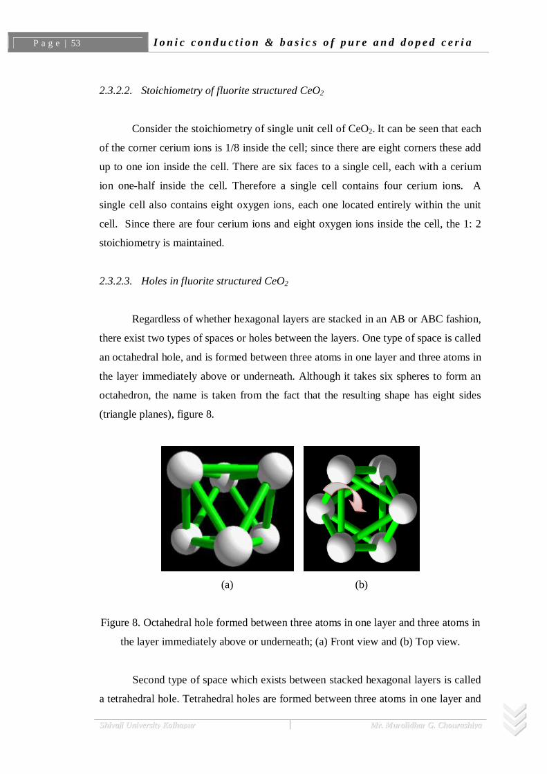
2.3.2.3. Holes in fluorite structured CeO2
Regardless of whether hexagonal layers are stacked in an AB or ABC fashion,
there exist two types of spaces or holes between the layers. One type of space is called
an octahedral hole, and is formed between three atoms in one layer and three atoms in
the layer immediately above or underneath. Although it takes six spheres to form an
octahedron, the name is taken from the fact that the resulting shape has eight sides
(triangle planes), figure 8.
(a) (b)
Figure 8. Octahedral hole formed between three atoms in one layer and three atoms in
the layer immediately above or underneath; (a) Front view and (b) Top view.
Second type of space which exists between stacked hexagonal layers is called
a tetrahedral hole. Tetrahedral holes are formed between three atoms in one layer and

2.3. Cryst. Structure and elect. properties C H A P T E R T W O 54 | P a g e
SShhiivvaajjii UUnniivveerrssiittyy KKoollhhaappuurr MMrr.. MMuurraalliiddhhaarr GG.. CChhoouurraasshhiiyyaa
a single atom immediately above or underneath, figure 9.
(a) (b)
Figure 9. Tetrahedral hole formed between three atoms in one layer and a single atom
immediately above or underneath; (a) Front view and (b) Top view.
In the fluorite structured CeO2, the oxide ions reside within the tetrahedral
holes formed by the face-centered cubic array of cerium ions, and the octahedral holes
are vacant. Figure 10 illustrates incorporation of oxide ion in the hole. Figure 11
illustrates stack of ceria with oxygen ion residing in tetrahedral holes and the vacant
octahedral holes.
(a) (b) (c)
(d) (e) (f) (g)
Figure 10. Illustration of (a-b) tetrahedral and (c-g) octahedral holes in CeO2.

P a g e | 55 I o n i c c o n d u c t i o n & b a s i c s o f p u r e a n d d o p e d c e r i a
SShhiivvaajjii UUnniivveerrssiittyy KKoollhhaappuurr MMrr.. MMuurraalliiddhhaarr GG.. CChhoouurraasshhiiyyaa
(a) (b)
Figure 11. Illustration of (a) filled tetrahedral hole by oxide ion and (b) vacant
octahedral hole (shown by hollow circles) in fluorite CeO2 structure
Why oxide ion in fluorite structure resides in tetrahedral holes rather than octahedral holes?
It is obviously, due to its stoichiometry. There are two oxygen atoms for every
one cerium atom. Since an array of N atoms results in the formation of N octahedral
holes, there would simply not be enough spaces for all oxygen atoms (stoichiometry
of Ce: O is 1: 2). Suppose, the position of ions are reversed, with the oxygen ions
forming the face-centered cubic array, there would be enough cerium ions to fill only
1/4 of the tetrahedral holes or 1/2 of the octahedral holes; this would be very
inefficient. Theoretically, the descriptions of the fluorite structure given above are
inaccurate in the sense that because the oxygen ions are in fact larger than the cerium
ions, they therefore do not "fit inside" the tetrahedral holes. As can be seen in figure
11b, the cerium ions form a sort of "expanded" face-centered cubic structure and do
not physically touch each other.
However materials such as Li2O, form an anti-fluorite structure i.e. the
positions of the anions and cations are revered. The O anions are in the f.c.c. positions
and the Li cations form a simple cubic array.
2.3.3. Defect structure of ceria
Defects in a crystal structure are nothing but the deviations from the perfect

2.3. Cryst. Structure and elect. properties C H A P T E R T W O 56 | P a g e
SShhiivvaajjii UUnniivveerrssiittyy KKoollhhaappuurr MMrr.. MMuurraalliiddhhaarr GG.. CChhoouurraasshhiiyyaa
periodic lattice. Though there are many ways in which crystal imperfections are
observable, such as dislocations, surfaces and pores, all of these are essentially
collections of zero dimensional point defects. Point defects consist of vacant lattice
sites, atoms in non-regular lattice positions (interstitials) and occurrence of impurity
atoms instead of host position. Many properties (e.g. conductivity, luminescence and
diffusion) are influenced by the existence of these defects, which is particularly true
for inorganic solids. Furthermore, it is not possible to produce a single crystal free of
defects. Finally, as temperature increases, defects become even more significant.
In general, there are two types of defects called intrinsic and extrinsic defects.
Former type of defects formed in a crystal is due to thermal disorder while extrinsic
defects are created by impurities incorporated in hosts during its synthesis,
introduction of alliovalent dopants or by the oxidation-reduction process. The creation
and annihilation of defects in crystal lattices are in general described using so called
“Kröger-Vink” notations. Kröger-Vink notation is set of conventions used to describe
electrical charge and lattice position for point defects in crystals. It was proposed by
F.A. Kröger and H.J. Vink [6].
2.3.3.1. General format of Kröger-Vink notation
‘M’ corresponds to the species. These would include:
Atom – e. g. Si, Ni, O, Cl, Ce, etc.
Vacancies – V
Electrons – e
Holes – h
‘S’ indicates the lattice site that the species occupies. For instance, Ni might
occupy a Cu site. In this case, M would be replaced by Ni and S would be replaced by
Cu. The site may also be a lattice interstice. In this case the symbol ’i’ is used.
‘C’ corresponds to the electric charge of the species relative to the site that it
occupies. To continue the previous example, Ni often has the same valency as Cu, so
the relative charge is zero. To indicate null charge, ‘ ’ is used (also nothing is
written). A single ‘ ’ indicates a single positive charge, while two would represent

P a g e | 57 I o n i c c o n d u c t i o n & b a s i c s o f p u r e a n d d o p e d c e r i a
SShhiivvaajjii UUnniivveerrssiittyy KKoollhhaappuurr MMrr.. MMuurraalliiddhhaarr GG.. CChhoouurraasshhiiyyaa
two positive charges. Finally, ' signifies a single negative charge, so two, would
indicate a double negative charge.
For examples:
: An aluminum ion sitting on an aluminum lattice site, with neutral
charge.
: A nickel ion sitting on a copper lattice site, with neutral charge.
: A chlorine vacancy, with single positive charge.
: A calcium interstitial ion, with double positive charge.
: An electron. A site isn't normally specified.
2.3.3.2. Intrinsic defects (or disorders) in ceria
This type of disorders in lattices requires thermal activation, rather than the
addition of impurities or solutes. Hence, it is named as intrinsic (i.e. inherent)
disorder. As temperature is raised, contributions to the free energy due to the entropy
term (degree of disorder) increases the number of atoms that are displaced from
regular lattice positions. Since, increase in entropy leads to increase in the magnitude
of lattice vibrations and configurational term. However, the concentration of defects is
able to remain finite. Since, an increase in thermal energy also gives rise to an
increase in entropy, thus reducing the free energy, which in turn limits the defect
formation in lattices.
The two most common types of crystalline intrinsic defects in ionic materials
are Frenkel and Schottky defects. Frenkel disorder results when an atom is displaced
from its regular site to an interstitial site, thus forming a defect pair (figure 12a).
Several compounds including CeO2, readily exhibit Frenkel disorder. For example,
UO2, CaF2, etc. all demonstrate the Frenkel anion type of disorder (i.e. anion
interstitials and anion vacancies) while AgCl, AgBr and Fe3O4 all exhibit cation
Frenkel disorder.
The other type of intrinsic disorder is Schottky disorder. Schottky disorder is
the simultaneous occurrence of cation and anion vacancies in thermal equilibrium
(figure 12b). In this case, vacancy defects must be formed in a number which
maintains the electro-neutrality of the lattice.

2.3. Cryst. Structure and elect. properties C H A P T E R T W O 58 | P a g e
SShhiivvaajjii UUnniivveerrssiittyy KKoollhhaappuurr MMrr.. MMuurraalliiddhhaarr GG.. CChhoouurraasshhiiyyaa
(a) (b)
Figure 12. (a) Frenkel disorder and (b) Schottky disorder in an ionic crystal, where the
square denotes a vacancy left by an ion which has displaced from its original site.
In general terms, Frenkel disorder is more likely when the anion and cation
differ significantly in size and when the lattice polarization is pronounced. When the
anions and cations are of similar size (as is the case of NaCl) Schottky disorder is
favored. In close packed materials, there is little lattice space to accommodate an
interstitial ion. It follows that Frenkel disorder is not favored in these materials.
Conversely, in open structures such as of CeO2 (fluorite structure), Frenkel disorder is
more easily accommodated.
The sources of intrinsic disorder in stoichiometric CeO2 due to thermal
excitation are represented as follows (using Kröger-Vink notation),
E = 3.33eV Schottky (A)
E = 2.81eV Anion Frenkel (B)
E = 8.86eV Cation Frenkel (C)
which are the (A) Schottky, (B) Anion Frenkel, and (C) Cation Frenkel defect
mechanisms, respectively. The energies for the individual defects, as well as the
reaction enthalpies are listed in table 4.

P a g e | 59 I o n i c c o n d u c t i o n & b a s i c s o f p u r e a n d d o p e d c e r i a
SShhiivvaajjii UUnniivveerrssiittyy KKoollhhaappuurr MMrr.. MMuurraalliiddhhaarr GG.. CChhoouurraasshhiiyyaa
Schottky energy
per defect
Anion Frenkel
energy per defect
Cation Frenkel
energy per defect
16.06 83.52 -10.43 -65.80 3.33 2.81 8.86
Table 4: Disorder reaction energies (in eV).
From the table 4 it can be seen that the possibility of cation Frenkel defects
forming is extremely low. The Schottky defect energy is higher than the anion Frenkel
energy, which implies that . Hence, the most likely form of intrinsic
disorder is anion Frenkel. In the agreement of the above, Faber et al. [7] examined the
electron density distribution using XRD and concluded that the amount of interstitial
Ce ( ) is less than 0.1% of the total defect concentration in CeO2-x. However, the
anion Frenkel energy is still quite high, thus such disorder will be flooded by the
effect of non-stoichiometry in CeO2 (i.e. by doping).
2.3.3.3. Extrinsic defects (disorder) in ceria
Intrinsic disorder is differentiated from extrinsic disorder on the basis of its
reaction with ambiance. Intrinsic disorder includes only thermally activated defect
processes which occur within an otherwise perfect lattice where there is no reaction
with the environment. Essentially, extrinsic disorder includes reaction with gaseous
species from the environment that are constituents of the lattice and reaction with
species from the environment that are not local to the lattice. Therefore, extrinsic
disorder includes defects resulting from oxidation or reduction of lattices and/or the
presence of dopants, impurities, etc. in a lattice.
To explain the former process in case of ceria, the reduction of ceria is
possible at elevated temperatures with either in oxygen deficient environment or
hydrogen rich environments. The oxidation-reduction (redox) processes of ceria are
responsible for the creation of extrinsic defects which certainly produces non-
stoichiometry in lattices. The process of ceria reduction in oxygen deficient
environment, using Kroger Vink notation, may be written as,
, (D)

2.3. Cryst. Structure and elect. properties C H A P T E R T W O 60 | P a g e
SShhiivvaajjii UUnniivveerrssiittyy KKoollhhaappuurr MMrr.. MMuurraalliiddhhaarr GG.. CChhoouurraasshhiiyyaa
while in the case of H2 environment it may be written as,
, (E)
To understand the stoichiometry and non-stoichiometry in lattices, consider its
historical development. Initially the stoichiometry was defined as the constant and
fixed ratio of elemental constituents of a chemical compound. The concept of
stoichiometry was proposed by Dalton’s atomic hypothesis [8], and the Law of
Definite Proportions, which was a product of the hypothesis. This law states that the
constituent elements of any compound exist in distinct proportions. This law was the
topic of debate between Proust, a supporter of the law, and his fellow Frenchman
Berthollet, who suggested that the composition of solid compounds is by no means
constant. Berthollet lost that debate, but was justified many years later in a paper by
Kurnakov, where it was found that the constituents of various intermetallics varied in
composition [9]. Schottky and Wagner also suggested that all inorganic solids are
inherently non-stoichiometric [10].
The non-stoichiometry of metal oxides can be subdivided into two categories
with respect to exact stoichiometry: metal deficient or oxygen deficient. Non-
stoichiometry is a direct result of point defects and the extent of non-stoichiometry is
measured by the net concentration of these defects [11]. Just as the reactions for
Frenkel and Schottky disorder were electronically neutral, the reactions for non-
stoichiometry must also be neutral through the formation of complimentary point
defects (as presented in reactions (D) and (E)). In metal deficient oxides, if metal
vacancies are formed, they are complimented by electronic defects on either
remaining metal sites (increasing the valence state), on the oxygen site (lowering the
charge) or by a delocalized charge. If the metal sub-lattice remains intact, the non-
stoichiometry is aided by oxygen interstitial defects compensated by the electronic
defects mentioned above. It follows that for the oxygen deficient system, metal
interstitials or oxygen vacancies will be the predominant structural defects.
A possibly more clear example of extrinsic disorder, but still technologically
important, is the presence of impurity defects which are non-resident to the
compound. For example, doping a material (thus generating defects) can have
pronounced effects on a variety of properties.

P a g e | 61 I o n i c c o n d u c t i o n & b a s i c s o f p u r e a n d d o p e d c e r i a
SShhiivvaajjii UUnniivveerrssiittyy KKoollhhaappuurr MMrr.. MMuurraalliiddhhaarr GG.. CChhoouurraasshhiiyyaa
For example,
Doping Si with group V atoms Sb, As, P or group III atoms In, Al or B
creates charge carriers for n- and p- type semiconductors respectively.
In addition, the solution of CaCl2 lowers the density of KCl with the
production of K vacancies.
The cubic fluorite structure of ZrO2 can be stabilized with a variety of
oxides such as Y2O3 or CaO.
The cubic fluorite structure of CeO2 shows drastic increase in ionic
conductivity after doping the host by Gd2O3 or Sm2O3.
The later examples of ZrO2 and CeO2 are particularly important in
electrochemical applications due to its enhanced ionic conductions by the generation
of anion vacancies.
Excess oxide (anion) vacancies can be introduced in CeO2 by doping with oxides of
metals with lower valencies (3 or 2), e.g. dissolution of Gd2O3, CaO in CeO2, which
may be represented as follows,
(F)
(G)
Already existing oxide vacancies may be removed by doping with oxides of
higher valency than 4, e.g. dissolution of Nb2O5 in CeO2, which may be represented as
follows,
(H)
2.3.3.4. Defect concentrations in pure and doped ceria
Pure ceria exhibits a dramatic drop in the concentrations of oxide vacancies
and oxide interstitial ions with increase in temperature. However, these concentrations

2.3. Cryst. Structure and elect. properties C H A P T E R T W O 62 | P a g e
SShhiivvaajjii UUnniivveerrssiittyy KKoollhhaappuurr MMrr.. MMuurraalliiddhhaarr GG.. CChhoouurraasshhiiyyaa
remain virtually constant in Gd/Sm doped ceria. Interstitial oxygen ions in ceria-
containing compounds are likely to form during sample processing. When oxygen-
deficient material is oxidized to CeO2 or (Ce, Gd) O2, absorbed oxygen ions may at
first enter the roomier octahedral sites, rather than fill the spatially tight tetrahedral
sites. If annealing temperature is not high enough they may not be able to overcome a
potential barrier to get into the regular tetrahedral sites, and remain in the octahedral
sites. However, only when the sample is treated at sufficiently high temperature
thermally activated interstitial ions may enter to regular tetrahedral sites and
recombine with vacancies.
Because of the slightly larger ionic radius of gadolinium/samarium ions,
mixing of Gd2O3/Sm2O3 with ceria will increase the lattice constant and produce the
atomic-level relaxation at the smaller tetrahedral sites, making them easier to reach
for the interstitial oxygen ions than in pure ceria. This may explain the enhanced
stability of oxygen defects against thermal aging in doped ceria. However, the easier
access to octahedral sites (since it is inherently roomier) and tetrahedral sites
(achieved by doping) for oxide ion facilitates enhanced ionic conductivity in doped
ceria by employing both the possible mechanisms, namely, vacancy and interstitial
hopping mechanism (figure 13). At the same time, the interstitial oxygen ions are the
"active" ions that provide necessary mobility of oxide ions, which is a crucial
condition for ceria to function as an oxide ion conductor.
Figure 13. Schematic of showing two possible mechanisms for the movement of ions
through a lattice.

P a g e | 63 I o n i c c o n d u c t i o n & b a s i c s o f p u r e a n d d o p e d c e r i a
SShhiivvaajjii UUnniivveerrssiittyy KKoollhhaappuurr MMrr.. MMuurraalliiddhhaarr GG.. CChhoouurraasshhiiyyaa
2.3.4. Ionic conductivity in ceria and doped ceria
Because of their role as the electrolyte in solid oxide fuel cells (SOFCs),
yttrium doped zirconia (YSZ) and Gd doped ceria (GDC) are technologically
important oxygen ion conductors. The dopants in these materials serve to introduce
anion defects that perhaps increase the ionic conductivity. As discussed in earlier
section ceria possesses cubic fluorite structure from room temperature to its melting
point while in case of zirconia it is only possible at high temperatures. This distinct
property of ceria is advantageous to design SOFCs which can operate at
comparatively less temperatures.
Doping of ceria is usually performed by substituting lower valence cations
into the lattice, with the additional effect of introducing oxygen vacancies, however
overall charge neutrality in lattice is maintained. These oxygen vacancies supply the
equivalent sites allowing the oxygen ions to migrate (by hopping mechanism) and are
the requirement for high ionic conductivity. A further remarkable feature of the
fluorite structured ceria is that it is able to sustain a high degree of substitution and
consequent non-stoichiometry, making these structures very highly disordered
materials. Doping of the fluorite structured oxide for improvement in oxide ion
conductivity is usually achieved by substitution of the host cation with a rare earths.
Examples of such materials are doped zirconia, doped ceria etc. with the general
formula Re1-xAxO2- , where ‘A’ is cations and ‘Re’ is the rare earth dopants.
The ionic motion in fluorite-based systems is the well-established vacancy
based hopping mechanism, where one vacancy shifts position with a neighboring
oxygen ion in a normal lattice position (figure 14). The easiest jump is along the edge
of the cube formed by eight oxygen ions/vacancies.
In general, the ideal solid electrolyte, particularly oxide ion conductor, possess
the following properties,
A large number of the ions of one species should be mobile. This requires a large
number of empty sites, either vacancies or accessible interstitial sites.
o Empty sites are needed for ions to move through the lattices.

2.3. Cryst. Structure and elect. properties C H A P T E R T W O 64 | P a g e
SShhiivvaajjii UUnniivveerrssiittyy KKoollhhaappuurr MMrr.. MMuurraalliiddhhaarr GG.. CChhoouurraasshhiiyyaa
The empty and occupied sites should have similar potential energies with a low
activation energy barrier for jumping between neighboring sites.
o High activation energy decreases carrier mobility, very stable sites (deep
potential energy wells) lead to carrier localization
The structure should have solid framework, preferably three dimensional,
permeated by open channels.
o The migrating ion lattice should be "molten", so that a solid framework of the
other ions is needed in order to prevent the entire material from melting.
The framework ions (usually anions) should be highly polarizable,
o Such ions can deform to stabilize transition state geometries of the migrating
ion through covalent interactions.
Optimization of oxygen transport in fluorite related systems, therefore, could
be concentrated on simple considerations of dopants ionic size and charge. To avoid
lattice distortion and strong defect association, host cation and dopants should have
similar sizes and minimum charge difference. Dopants concentrations also should
have an ideal level, since as high concentrations of defects increases defect interaction
and reduction in ionic conductivity could cause [12, 13].
(a) (b)
Figure 14. (a) Schematic view of the vacancy motion mechanism in the fluorite
structure. Ions as filled circles, oxygen vacancies as empty circles. (b) Positions of
various species in a disordered unit cell of Gd doped ceria.
P a g e | 65 I o n i c c o n d u c t i o n & b a s i c s o f p u r e a n d d o p e d c e r i a
SShhiivvaajjii UUnniivveerrssiittyy KKoollhhaappuurr MMrr.. MMuurraalliiddhhaarr GG.. CChhoouurraasshhiiyyaa
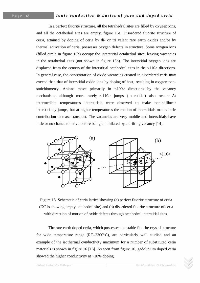
In a perfect fluorite structure, all the tetrahedral sites are filled by oxygen ions,
and all the octahedral sites are empty, figure 15a. Disordered fluorite structure of
ceria, attained by doping of ceria by di- or tri valent rare earth oxides and/or by
thermal activation of ceria, possesses oxygen defects in structure. Some oxygen ions
(filled circle in figure 15b) occupy the interstitial octahedral sites, leaving vacancies
in the tetrahedral sites (not shown in figure 15b). The interstitial oxygen ions are
displaced from the centers of the interstitial octahedral sites in the <110> directions.
In general case, the concentration of oxide vacancies created in disordered ceria may
exceed than that of interstitial oxide ions by doping of host, resulting in oxygen non-
stoichiometry. Anions move primarily in <100> directions by the vacancy
mechanism, although more rarely <110> jumps (interstitial) also occur. At
intermediate temperatures interstitials were observed to make non-collinear
interstitialcy jumps, but at higher temperatures the motion of interstitials makes little
contribution to mass transport. The vacancies are very mobile and interstitials have
little or no chance to move before being annihilated by a drifting vacancy [14].
Figure 15. Schematic of ceria lattice showing (a) perfect fluorite structure of ceria
(‘X’ is showing empty octahedral site) and (b) disordered fluorite structure of ceria
with direction of motion of oxide defects through octahedral interstitial sites.
The rare earth doped ceria, which possesses the stable fluorite crystal structure
for wide temperature range (RT–2300 C), are particularly well studied and an
example of the isothermal conductivity maximum for a number of substituted ceria
materials is shown in figure 16 [15]. As seen from figure 16, gadolinium doped ceria
showed the higher conductivity at ~10% doping.

2.3. Cryst. Structure and elect. properties C H A P T E R T W O 66 | P a g e
SShhiivvaajjii UUnniivveerrssiittyy KKoollhhaappuurr MMrr.. MMuurraalliiddhhaarr GG.. CChhoouurraasshhiiyyaa
Figure 16. The isothermal conductivity of some ceria solid solutions at temperatures
close to 200°C [15].
2.3.5. Electrical behavior of pure and doped ceria
2.3.5.1. Influence of doping
Ceria can be classified as mixed conductor showing both electronic and ionic
conduction. Its electrical properties are strongly dependent upon temperature, oxygen
partial pressure and presence of impurities/dopants. At high temperatures and low
oxygen partial pressures, ceria behaves as an n-type semiconductor and electrons
liberated following the reduction are the primary charge carriers.
(I)
However, transition from n-type to p-type conduction is observed at lower

P a g e | 67 I o n i c c o n d u c t i o n & b a s i c s o f p u r e a n d d o p e d c e r i a
SShhiivvaajjii UUnniivveerrssiittyy KKoollhhaappuurr MMrr.. MMuurraalliiddhhaarr GG.. CChhoouurraasshhiiyyaa
temperatures and higher oxygen partial pressures near stoichiometric composition,
where electronic conductivity arises from holes introduced by impurities ( ).
(J)
(K)
Ionic conductivity observed in ceria is due to the mobility of oxide ion
vacancy by hopping mechanism. It is always much lower than the electronic
conductivity in pure reduced ceria. However, the situation gets reversed in case of
ceria doped with oxides of two or three-valent metals due to the introduction of oxide
ion vacancy in host. The electronic conductivity in air may be very low and the doped
ceria under these conditions are excellent solid electrolytes. The most important
parameter which influences the ionic conductivity in fluorites is the cation match of
dopants atom and host atom with the critical radius, rc. The ratio of dopant cation to
host cation must be closer to unity. Hence the earlier experimental as well as
theoretical study showed that the ionic conductivity increases with increasing ionic
radius of dopant in ceria, from Yb to Sm, but decreased at ddopant > 0.109 nm and the
peak ionic conductivity is observed for doping of Gd (0.108nm) and Sm (0.109nm) in
ceria.
2.3.5.2. The temperature dependence
Since, in general, ionic conductivity, i is defined same as electrical
conductivity (eq. 2.1). The temperature dependence variation of ionic conductivity is
given by eq. 2.5, takings logs of both sides gives,
(2.7)
Plotting ln T vs. 1/T should produce a straight line with a slope of –Ea.

2.3. Cryst. Structure and elect. properties C H A P T E R T W O 68 | P a g e
SShhiivvaajjii UUnniivveerrssiittyy KKoollhhaappuurr MMrr.. MMuurraalliiddhhaarr GG.. CChhoouurraasshhiiyyaa
Figure 17. Typical plot of ln T vs. 1000/T for solid electrolyte.
The actual temperature dependence of the electrical conductivity in general
can be shown as the three regions according to Kilner and Walters [16]. In region I,
which appeared at high temperatures (not shown in figure 16), the electrical
conduction is determined by the intrinsic defects (Schottky or Frenkel) in the crystal.
In region II, electrical conduction is controlled by the population of charge-carrying
defects determined by an alliovalent dopant or impurity. In region III, usually at low
temperatures, the population of charge carrying defects is determined by the
thermodynamic equilibrium between the free defects and the associated pairs. Since
doped cerium oxides (fluorite structured) have a large number of oxygen vacancies,
they only show the regions II and III.
In figure 17, differences in slopes are evident, which can be seen even in very
pure crystals. At low temperatures extrinsic vacancies are most important. The
concentrations of intrinsic vacancies are so small at low temperature that they may be
ignored. The number of vacancies will be essentially constant; m (slope) in the
extrinsic region thus will only depend on the mobility of mobile species due to

P a g e | 69 I o n i c c o n d u c t i o n & b a s i c s o f p u r e a n d d o p e d c e r i a
SShhiivvaajjii UUnniivveerrssiittyy KKoollhhaappuurr MMrr.. MMuurraalliiddhhaarr GG.. CChhoouurraasshhiiyyaa
extrinsic defects, with the temperature dependence.
At high temperatures the concentration of intrinsic defects has increased so
that it is similar or greater than the concentration of extrinsic defects. Thus in this
region, for a system with Schottky defects and with Frenkel defects a plot of ln T vs.
1/T gives a larger value for the activation energy (E), because it depends on both the
activation energy for the cation jump ( Hm) and the enthalpy of formation of a
Schottky and Frankel defect, given as
Es = Ea + ½ Hs for a system with Frenkel defects
EF = Ea + ½ HF for a system with Schottky defects
respectively.
Additionally, according to Zhang et al [17], for a polycrystalline oxygen-ion
electrolyte, the activation energy for total ionic conduction should come from three
sources, that is, the enthalpy of migration of oxygen ions ( Hm), the association
enthalpy of complex defects ( Ha), and the activation energy for the grain boundary
conduction (Egb). However, in a low temperature range ( 500°C); these three sources
simultaneously limit the total ionic conductivity. Further with increasing temperature,
the grain boundary effect and the association enthalpy of complex defects
(e.g. ) gradually disappears. As a result, only the enthalpy of migration of
oxygen ions ( Hm) plays a major role in limiting the total ionic conductivity and thus
the activation energy at high temperatures e.g. 500–700°C could be further smaller
than that of at 250–500°C.
Reference:
References[1] J. B. Goodenough, H. Y. P. Hong, J. A. Kafalas, Mat. Res. Bull., 11 (1976) 203.
[2] P. Debye, H. Falkenhagen, Phys. Z., 29 (1928) 121.
[3] P. Debye, E. Hiickel, Phys. Z., 24 (1923) 185.
[4] Steele, B. C. H. in High Conductivity Solid Ionic Conductors, ed. T.
Takahashi, World Scientific, Singapore, (1989) 402.

References C H A P T E R T W O 70 | P a g e
SShhiivvaajjii UUnniivveerrssiittyy KKoollhhaappuurr MMrr.. MMuurraalliiddhhaarr GG.. CChhoouurraasshhiiyyaa
[5] CRC Handbook of Chemistry and Physics for 21st century Copyright CRC
Press LLC 2002.
[6] F.A. Kröger, Chemistry of Imperfect Crystals, North-Holland, Amsterdam,
(1964) 194.
[7] J. Faber, C. Geoffroy, A. Roux, App. Phys. A: Mater. Sci. Process. 49 (1989)
225.
[8] K. E. Sickafus, R. J. Hanrahan Jr., K. J. McClellan, J. N. Mitchell, C. J.
Wetteland, D. P. Butt, P. III. Chodak, K. B. Ramsey, T. H. Blair, K.
Chidester, Hj. Matzke, K. Yasuda, R. A. Verral, N. Yu, Am. Ceram. Soc.
Bull., 78 (1999) 1.
[9] M. Leslie. Program cascade, description of data sets for use in crystal defect
calculations. Technical report, SERC Daresbury Laboratory Report
DL/SCI/TM31T, 1982.
[10] H. Kleykamp, J. Nucl. Mater., 131 (1985) 221.
[11] J. van Geel, Hj. Matzke, J. Magill, BNES, 36 (1997) 305.
[12] J.A. Kilner and B.C.H. Steele, in: Nonstoichiometric Oxides, Academic Press
Inc., NY 1981, pp. 233-269.
[13] J. Moscinski, P. W. M. Jacobs, Proceedings of the Royal Society of London.
Series A, Mathematical and Physical Sciences, 398 (1985) 173.
[14] E.C. Subbarao and H.S. Maiti, Solid State lonics 11 (1984) 317.
[15] J. A. Kilner, Solid State Ionics 129 (2000) 13.
[16] J.A. Kilner, C.D. Walters, Solid State lonics 6 (1982) 253.
[17] Zhang T.S., Ma J., Cheng H., Chan S.H., Mater. Res. Bull. 41 (2006) 563.