chapter 9: on-site sanitation 9.1 overview of on-site
TRANSCRIPT

Part A: Engineering
9 - 1
CHAPTER 9: ON-SITE SANITATION
CHAPTER 9: ON-SITE SANITATION
9.1 OVERVIEW OF ON-SITE SANITATION
The areas that are not served by piped sewer systems can adopt on-site systems. The treatment can be either on-site or off-site like in the case of septage management. These are interim measures till a decentralised or a full sewerage system is implemented.
It is strongly recommended that the town planning agencies / authorities / ULB / metropolitan development authorities earmark adequate spaces for laying of sewer lines, construction of SPS and STP.
9.1.1 On-site Sewage Treatment System
Unlike off-site centralized treatment (sewerage), on-site sewage treatment features individual and distributed treatment. The on-site treatment system includes a wide range of facilities, such as a basic sanitation facility like a pit latrine, a simple sewage treatment system that consists of a septic tank and a soak pit for anaerobic treatment, and an advanced facility like Johkasou that treats sewage by sophisticated methods.
In an urban area with high population density, an STP intensively treats sewage collected by pipes laid over a wide area. The on-site system treats sewage near the source.
Accordingly, the latter uses various kinds of treatment technologies according to treatment scale and the surrounding conditions. Sludge generated in each on-site treatment facility is collected and treated separately.
9.1.2 On-siteClassification
This subsection summarizes the classification of toilets and on-site treatment methods as well as their features.
9.1.2.1Historical
The historical pit latrines are rather rudimentary sanitation facilities atleast serving to contain the spread of faecal organisms from the night soil and bringing about interactions between soil organisms and feacal organisms in the pit. These have since been upgraded to various types as in Figure 8.3. In respect of community toilets, installations such as Dewats have also come up.
9.1.2.2SimpleTreatmentMethod
A septic tank system is a typical on-site treatment facility that consists of a septic tank and a soak pit and employs two technologies: the first is anaerobic treatment and the second is the methods of letting treated sewage penetrate the ground.
It shows stable performance, provided that the water temperature is kept suitable to digestion and the soil has good permeability.

Part A: Engineering
9 - 2
CHAPTER 9: ON-SITE SANITATION
However, the septic tank reduces BOD up to 50%, so if underground penetration is impossible due to high groundwater levels, rocky strata, non-availability of land for soak-pit, another method must be employed to hygienically treat sewage passing through the septic tank such as anaerobic filter and contact aeration. When this system is applied to an urban area with high population density, care must be taken not to have a negative effect on the surrounding environment.
9.1.2.3AdvancedTreatmentSystem Conventional septic tanks system, if properly designed and with proper septage removal frequency can effectively remove about 40-50% BOD and 50-70% TSS. However, due to partial treatment and associated health hazards the effluent can only be discharged into soak pits. Due to recent groundwater pollution related episodes, unavailability of space for soak pits and under rocky strata, soak pits are avoided and the effluent is commonly discharged to open stormwater drains. Hence, it is causing another type of pollution menace such as unsightly conditions, eutrophication, odour, vector and water related diseases.
Some of the interim solutions are the improved design of septic tanks such as anaerobic baffled reactor or the post treatment of septic tank effluents by anaerobic filters. Both configurations can partially solve the pollution related problems by increasing the overall BOD removal to more than 70%. These systems can lessen the burden of organic pollution without any extra energy cost. The capital cost of these systems may not be more than 20-30% of the conventional septic tank cost. Nevertheless, due to the limitation of anaerobic sewage treatment, these systems cannot bring down the BOD and TSS levels up to the national effluent discharge standards. Hence, alternate solution could be the aerobic type post treatment such as contact aeration. This system can bring down effluent BOD to less than 30 mg/l and TSS to less than 50 mg/l but at the expense of electrical power requirement for 24×7 operating air blower with standby equipment and standby power.
One such system is the Japanese type Johkasou system. This system is an integrated septic tank-anaerobic filter-contact aeration-final settling tank and effluent disinfection facility. However, due to higher cost considerations, these systems may be affordable only in very fragile environment. These systems have also been upgraded for even nitrogen removal by providing internal recirculation. The detail of these systems is provided in the following sections. There are many other similar package treatment systems elsewhere that can also be used.
9.2 THE PROHIBITION OF EMPLOYMENT AS MANUAL SCAVENGERS AND THEIR REHABILITATION ACT, 2013
The aforesaid act was notified by the GOI in September 2013. The act shall come into force from 6th December 2013. The text of the act as in the Gazette is in Appendix A 1.1. The time frame specified under the Act for the fulfilment of responsibilities and carrying out certain activities are mentioned in Appendix A 1.2.
9.3 INTERIM MEASURES
There are various on-site systems which can be used but with a caution to prevent ground water and surface water pollution due to indiscriminate disposal of sewage from these on-site systems.

Part A: Engineering
9 - 3
CHAPTER 9: ON-SITE SANITATION
9.3.1 PublicandCommunityToilets
A public toilet, a kind of common toilet installed in stations and on streets, is open to everyone rather than specified users. In contrast, a community toilet has limited users such as residents. These common toilets are controlled by local governments, residents, or private sector organizations. A common toilet normally has two sections: one is for males and the other is for females. In addition, another section special to persons in a wheelchair (unisex) is sometimes provided.
In general, an on-site common toilet includes a special sewage treatment facility such as a septic tank. The flow rate of sewage to be treated is derived from the total number of users based on how many toilet bowls are installed and how frequently they are used.
The toilet is equipped with a water supply unit, a ventilator, and a lighting device. Figure 9.1 shows example arrangements of faeces, urine, and hand-washing units.
Figure 9.1 Examples of common toilet arrangements
Exampleofdesign
The following shows an example of estimating the number of public toilet users.
BasicSetting
Number of toilet bowls [c]: 10 (in total)
Totalnumberofusers[n]
n = 16c = 16 × 10 = 160
9.3.2 MobileToilet
Mobile toilets are temporarily installed in places where there is no toilet, such as shelters during natural disaster, venues for events, and construction sites, or where the number of existing toilets is short. A mobile toilet box has a tank for storing excreta in its lower part. If the tank is full, a vacuum tanker collects the stored sewage. Each toilet has a single room or multiple rooms with a hand washing unit, which is selected according to the flexibility of installation sites and ease of transport by a truck. In addition, there is a mobile flush toilet that is equipped with a water tank and a pedal.

Part A: Engineering
9 - 4
CHAPTER 9: ON-SITE SANITATION
Figure 9.2 Mobile toilet
9.3.3 PourFlushWaterSealLatrine
In a conventional water flush latrine, the excreta is normally flushed with 10 to 14 litres of water from a cistern. In a pour flush latrine, as the name suggests, excreta is hand flushed by pouring about 1.5 to 2.0 litres of water. These pour-flush leaching pit latrines were first developed in India in mid-forties with a single leach pit and squatting pan placed over it. When the pit in use gets filled up another pit is dug and the squatting slab is removed and placed over the new pit. The first pit is covered with earth and the excreta is allowed to digest. After one or two years, the digested excreta is used as manure.
In the late fifties, a modified design of the system was developed. In this system the leach pit is kept away from the seat instead of placing it underneath the pan. In a single pit system, desludging has to be done almost immediately after the pit has been filled up to enable its re-use; this involves handling of fresh and undigested excreta containing pathogens which is a health hazard. Single leach pit is appropriate only if it is desludged mechanically by a vacuum tanker. To overcome this shortcoming, the twin-pit design was introduced and in this case when one pit is full, the excreta is diverted to the second pit. The filled up pit can be conveniently emptied after 1.5 to 2 years, when most of the pathogens die off. The sludge can safely be used as manure. Thus the two pits can be used alternately and perpetually.
With simple care, pour-flush water-seal latrine is a very satisfactory and hygienic sanitation system and hence it can be located inside the house since the water-seal prevents odour and insect nuisance from the pit.
Stepping on the latter activates a manual pump to cause washing water to flow. The box is made by assembling fiberglass-reinforced plastic (FRP) side panels, so its weight is light. Local governments keep these toilets to prepare for disasters and events, or rental companies lease them. The mobile toilet features easy installation work on the ground. Figure 9.2 shows a mobile toilet having faeces, urine, and hand washing units.

Part A: Engineering
9 - 5
CHAPTER 9: ON-SITE SANITATION
9.3.3.1DesignandMaterials
9.3.3.1.1SquattingPan,Trap,Footrests,andConnectingDrain
The squatting pan is of special design with steep bottom slope 25 - 28° and a trap having 20 mm water seal set on a cement concrete floor. The hydraulic design of the pan is such that the human excreta can be flushed by pouring only 1.5 to 2 litres of water. The squatting pan and trap design details are shown in Figure 9.3.
Source: CPHEEO, 1993
Figure 9.3 Squatting pan and trap

Part A: Engineering
9 - 6
CHAPTER 9: ON-SITE SANITATION
Table 9.1 Material and other details for latrine unit
(A)- Ceramic, FRP, PP are smooth and require less water for flushing. FRP cheaper, lighter and
easier to transport than the other
(B)- The inlet pipe should project 100 mm in to the leach pit.A junction chamber of 250×250 mm
should be provided in case of pipe
Source: CPHEEO, 1993
The squatting pan can be of ceramic or glass reinforced plastic (GRP), High Density Polyethylene (HDPE) or Poly Vinyl Chloride (PVC), Polypropylene (PP), Cement mosaic or even concrete. The squatting pan is connected to the leaching pit through a trap and a pipe or covered drain. The design and material details for latrine units squatting pan, trap, footrest and the connecting drain are summarised below in Table 9.1.
9.3.3.1.2LeachPits/TwinPitLatrine
Leach pits serve a dual function of (a) storage and digestion of excreted solids and b) infiltration of the waste liquids and are therefore, to be designed on the basis of the following parameters:
• Sludge accumulation rate
• Long term infiltration rate of the liquid fraction across the pit soil interface
• Hydraulic loading on the pit
• Minimum period required for effective pathogen destruction
• Optimal pit emptying frequency.
9.3.3.1.2.1SludgeAccumulationRate
The sludge accumulation rate is a function of a wide range of variables including water table level, pit age, water and excreta loading rates, microbial conditions in the pit, temperature and local soil conditions and the type of material used for anal cleansing.

Part A: Engineering
9 - 7
CHAPTER 9: ON-SITE SANITATION
The leach pit is classified as wet or dry depending on whether the ground water table is above the bottom of pit or below. In dry pits, the pit volume needed is calculated on the basis of solids accumulation rate, but in wet pits though the sludge accumulation rate is lower - the sludge digestion rate is high in the presence of water, yet volume of pit has to be increased to prevent flooding due to surcharge of pits. The sludge accumulation rates given below in Table 9.2 may be used to calculate the pit volume.
Table 9.2 Sludge accumulation rates
(A) Effective Volume is the volume of the pit below the invert level of pipe or drain.
Source:CPHEEO, 1993
Table 9.3 Long term infiltration rates of different types of soils
Source: CPHEEO, 1993
9.3.3.1.2.2 LongTermInfiltrationRate
On account of clogging of soil pores around the leach pits, the long term infiltration capacity (after clogging) of the soil is always less than the natural percolative capacity. The recommended design values of the long term infiltrative capacity can be derived for the typical soil conditions as given below in Table 9.3.
9.3.3.1.2.3HydraulicLoading
The hydraulic loading rate is the total volume of liquids entering the leach pit and is expressed in litres per day although it is often more convenient to consider per capita loadings (litres per capita per day). For computing the pit hydraulic loading, sewage contribution of 9.5 litres per day per person, including water used for ablutions and flushing, urine, excreta, etc., can be taken as the basis.

Part A: Engineering
9 - 8
CHAPTER 9: ON-SITE SANITATION
Table 9.4 Size of leach pits
Note: (A) Depth from bottom of pit to invert level of incoming pipe or drain (all dimensions in mm)
Source: CPHEEO, 1993
The outer surface area (perimeter) of the pit from pit bottom to invert level of pipe or drain is to be considered for infiltration. The pit bottom is not taken into account as it gets clogged in course of time. The infiltration area required is the total flow in the pit per day divided by the long term infiltrative rate of the soil where pits will be located. The infiltrative area of leach pits, sized on the basis of sludge accumulation rate should conform to the computed infiltrative area.
9.3.3.1.2.4PathogenDestruction
After a period of almost all pathogens viruses, bacteria, protozoa and helminths die off in the leach pit or in the surrounding soil, but not Ascaris Lumbricoides (the large human round-worm) particularly if the leach pit is wet. After about one or one and a half years of storage in the pit, it may not be hazardous to handle the contents of the pit for use as manure.
9.3.3.1.2.5OptimalPitEmptyingFrequency
The minimum acceptable design interval between successive manual desludging of each twin leach pit could be one-and-a-half-years. However, to provide a reasonable degree of operational flexibility, it is desirable to provide three years storage volume in urban areas and two years in rural areas. 9.3.3.1.2.6SizeofPits
Sizes of leach pits, [designed as above for different number of users, using water ablution and for different subsoil water levels], with 3 years sludge storage volume, are in Table 9.4.
The surface area of these is adequate for soils with long term infiltrative rate down to 20 l/m2/day. The above depths should be increased by 300 mm to provide a free board depth of pit from invert level of pipe or drain to bottom of pit cover.
9.3.3.1.2.7 DesignofPitsunderDifferentConditions
A typical pour flush latrine with circular pits is shown in Figure 9.4.
In water logged area: The pit top should be raised by 300 mm above the likely level of water above ground level at the time of water logging. Earth should then be filled well compacted all round the pits up to 1.0 m distance from the pit and up to its top. The raising of the pit will necessitate raising of latrine floor also. A typical pour flush latrine in water logged areas is shown in Figure 9.5.
Part A: Engineering
9 - 9
CHAPTER 9: ON-SITE SANITATION
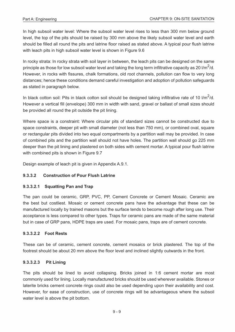
In high subsoil water level: Where the subsoil water level rises to less than 300 mm below ground level, the top of the pits should be raised by 300 mm above the likely subsoil water level and earth should be filled all round the pits and latrine floor raised as stated above. A typical pour flush latrine with leach pits in high subsoil water level is shown in Figure 9.6
In rocky strata: In rocky strata with soil layer in between, the leach pits can be designed on the same principle as those for low subsoil water level and taking the long term infiltrative capacity as 20 l/m2/d. However, in rocks with fissures, chalk formations, old root channels, pollution can flow to very long distances; hence these conditions demand careful investigation and adoption of pollution safeguards as stated in paragraph below.
In black cotton soil: Pits in black cotton soil should be designed taking infiltrative rate of 10 l/m2/d. However a vertical fill (envelope) 300 mm in width with sand, gravel or ballast of small sizes should be provided all round the pit outside the pit lining.
Where space is a constraint: Where circular pits of standard sizes cannot be constructed due to space constraints, deeper pit with small diameter (not less than 750 mm), or combined oval, square or rectangular pits divided into two equal compartments by a partition wall may be provided. In case of combined pits and the partition wall should not have holes. The partition wall should go 225 mm deeper than the pit lining and plastered on both sides with cement mortar. A typical pour flush latrine with combined pits is shown in Figure 9.7
Design example of leach pit is given in Appendix A.9.1.
9.3.3.2ConstructionofPourFlushLatrine
9.3.3.2.1SquattingPanandTrap
The pan could be ceramic, GRP, PVC, PP, Cement Concrete or Cement Mosaic. Ceramic are the best but costliest. Mosaic or cement concrete pans have the advantage that these can be manufactured locally by trained masons but the surface tends to become rough after long use. Their acceptance is less compared to other types. Traps for ceramic pans are made of the same material but in case of GRP pans, HDPE traps are used. For mosaic pans, traps are of cement concrete.
9.3.3.2.2FootRests
These can be of ceramic, cement concrete, cement mosaics or brick plastered. The top of the footrest should be about 20 mm above the floor level and inclined slightly outwards in the front.
9.3.3.2.3 Pit Lining
The pits should be lined to avoid collapsing. Bricks joined in 1:6 cement mortar are most commonly used for lining. Locally manufactured bricks should be used wherever available. Stones or laterite bricks cement concrete rings could also be used depending upon their availability and cost. However, for ease of construction, use of concrete rings will be advantageous where the subsoil water level is above the pit bottom.

Part A: Engineering
9 - 10
CHAPTER 9: ON-SITE SANITATION
Source: CPHEEO, 1993
Figure 9.4 Pour flush latrine with circular pits

Part A: Engineering
9 - 11
CHAPTER 9: ON-SITE SANITATION
Source:CPHEEO, 1993
Figure 9.5 Pour flush latrine in water logged areas

Part A: Engineering
9 - 12
CHAPTER 9: ON-SITE SANITATION
Source:CPHEEO, 1993
Figure 9.6 Leach pits in high subsoil water level

Part A: Engineering
9 - 13
CHAPTER 9: ON-SITE SANITATION
Source:CPHEEO, 1993
Figure 9.7 Pour flush latrine with combined pits

Part A: Engineering
9 - 14
CHAPTER 9: ON-SITE SANITATION
The lining in brick work should be 115 mm thick (half brick) with honey combing up to the invert level of incoming pipe or drain; the size of holes should be about 50 mm wide up to the height of the brick course. For ease of construction, holes should be provided in alternate brick courses. In case the soil is sandy and sand envelope is provided, the width of openings should be reduced to 12 to 15 mm. Where foundation of building is close to the pit, no holes should be provided in the portion of lining facing the foundation and in rest of the lining 12 to 15 mm wide holes should be provided. The lining above the invert level of pipe or drain up to the bottom of pit’s cover should be in solid brick work, i.e., with no openings.
The concrete rings used for lining should be 50 mm thick, about 450 mm in height and of required diameter in 1:3:6 cement concrete and have 40 mm circular holes staggered about 200 mm apart. The rings are not jointed with mortar, but are put one over the other. The rings above the invert level of pipe or drain should not have holes and are jointed with cement mortar.
9.3.3.2.4PitBottom
Except where precautions are to be taken to prevent pollution of water sources, the pit bottom should be left in natural condition.
9.3.3.2.5PitCover
Usually RCC slabs are used for covering the pits, but depending upon the availability and cost, flag stones can also be used. The RCC Slab may be centrally cast in pieces for convenience of handling.
9.3.3.2.6LeachPitConnection
The toilet pan is connected to the pit through a 75 mm brick channel of ‘U’ shape covered with loosely jointed bricks or 75 mm dia AC or PVC non-pressure pipe laid in 1:15 gradient. In case pipes are used, a chamber of minimum size 225 × 225 mm is provided at the bifurcation point to facilitate cleaning and allowing flow to one pit at a time. In case of drain, ‘Y’ portion of the drain serves the purpose by taking out the brick cover.
9.3.3.3PollutionSafeguards
In order to reduce the pollution risk of ground water and water sources, the following safeguards should be taken while locating the pits.
9.3.3.3.1SafeDistancefromDrinkingWaterSources
In dry pits or unsaturated soil conditions, i.e. where the height between the bottom of the pit and the maximum ground water level throughout the year is 2 m and more.
a) The pits can be located at a minimum distance of 3 m from the water sources such as tube wells and dug wells if the effective size (ES) of the soil is 0.2 mm or less, and
b. For coarser soils (with ES greater than 0.2 mm) the same distance can be maintained if the bottom of the pit is sealed off by an impervious material such as puddle clay or plastic sheet and 500 mm thick envelope of fine sand of 0.2 mm effective size is provided around the pit.

Part A: Engineering
9 - 15
CHAPTER 9: ON-SITE SANITATION
In wet pit saturated soil conditions, i.e. where the distance between the bottom of the pit and the maximum ground water level during any part of the year is less than 2 m,
a. The pits can be located at a minimum distance of 10 m from the water sources such as tube wells and dug wells if the ES of the soil is 0.2 mm or less, and
b. For coarser soils (with ES more than 0.2 mm), minimum distance of 10 m can be maintained if the pit is sealed off by an impervious material such as puddle clay or plastic sheet with 500 mm thick envelope of fine sand of 0.2 mm, effective size provided all round the pit.
9.3.3.3.2SafeDistancefromWaterSupplyMains
Lateral distance between the leach pit and the water mains should be at least 3 m provided the water table does not rise during any part of the year above the pit bottom and the inlet of the pipe or drain to the leach pit is below the level of water main. If the water table rises above the bottom of the pit, then the safe lateral distance should be kept as 8 m. If this cannot be achieved, then the pipes should be completely encased to a length of at least 3 m on either side of the pit.
When the pits are located either under the foot path or under the road, or the water supply main is within a distance of 3 m from the pits, the invert of the inlet pipe should be kept at least 1 m below the ground level. This would ensure that the liquid level in the pits does not reach the level of the water main as the water mains are generally laid at 0.9 m depth.
The water pipe should not cut across the pit, but where this is unavoidable; the water pipe should be completely encased for length of 3 m on either side of the pit including the portion across the pit to prevent infiltration or exfiltration.
A study is reported by National Institute of Technology, Calicut, Kerala in respect of safe distance in laterite type of soils (Biju.et.al.2011)
The study area had houses with either the septic tank-soak pit system or pit latrines, the latter being more common with open wells as the source of water at 1.2 m to 2.4 m below ground in laterite soil. The horizontal distance between well and the soak pit / pit latrines varied from 5 m to 31 m. The MPN of total coliform from nearly 35 wells was studied and it was found that the number of total coliform correlated with the length of a specific parabolic curve connecting the soak pit / pit latrine and the well. This relationship was used to calculate the safe distance between the soak pit / pit latrine and open well so that the total coliform was not exceeding the MoEF classification of class “A” water in the well water and which is “Drinking water source without conventional treatment but after disinfection” at total coliform of not exceeding 50/100 ml. The distance evaluated was 21 m, where the water table rises to the level of soak-pit / pit latrine and the well.
9.3.3.3.3LocationofPits
The ideal position for locating the pits is that the pits are placed symmetrically at the backside of pan. The pits may be located within the premises, under footpath or narrow lanes or under the road.

Part A: Engineering
9 - 16
CHAPTER 9: ON-SITE SANITATION
The minimum space between two pits should be equivalent to at least the effective depth (distance between the bottom of the pit and invert level of pipe or drain. Spacing can be reduced by providing an impervious barrier like cut off screen or puddle wall.
In many cases, the space available for constructing leach pits may be small and placement of pits near existing structure may be unavoidable. The digging of pits and subsequent seepage may disturb the soil around the pits.
The safe distance of the leach pits from the foundations of existing building depends upon the soil characteristics, depth as well as type of foundation of the structure, depth of the leaching pits etc., and varies from 0.2 to 1.3 m.
However, in cases where the leach pits are quite close to the existing building foundation, the opening in the brick work lining of the leach pit may be reduced to 12 to 15 mm.
Where the bottom of the pit is submerged below the maximum ground water level:
i. The top of the pits should be raised above the ground level, if necessary, so that the pipe into the pit is at least 0.75 m above the maximum ground water level.
ii) The sand envelope is taken up to 0.3 m above the top of the inlet pipe and confined suitably to exclude any surface drainage including rain water directly entering the sand envelope.
iii) In mound type latrines, 1 m high earth filling be provided at least 0.25 m beyond the sand envelope with the edges chamfered to lead away the rain or surface water, and
iv) The honeycomb brick work for the pit lining should be substituted by brick work in cement mortar 1:6 with open vertical joints, i.e. without mortar. Where sand is not available economically, local soil of effective size of 0.2 mm can also be used.
9.3.3.3.4SubsoilConditions
In depression and waterlogged areas, location of pits should be avoided, as far as possible, in depression where sewage or rain water is likely to remain collected all round and over the pits. If it cannot be avoided or the pits are to be constructed adjacent to ponds or tanks, then the top of pits should be raised to 0.6 m to 0.8 m above the ground level and earth filling should be done all around the pits up to a distance of 1.5 m right up to the pit top.
The raising of pit may necessitate raising the latrine floor also.
9.3.3.4NightSoilDigesters
The night soil can be anaerobically digested either alone or in combination with cattle dung. It is rich in nitrogen and phosphorus in comparison to cow dung.
The characteristics of night soil are different from the cow dung and are mentioned in Table 9.5 (overleaf).
Part A: Engineering
9 - 17
CHAPTER 9: ON-SITE SANITATION
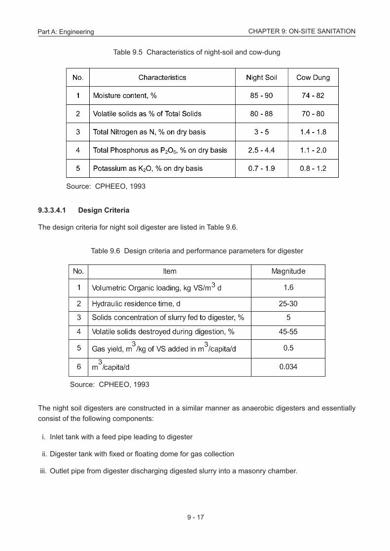
Table 9.5 Characteristics of night-soil and cow-dung
Source: CPHEEO, 1993
Table 9.6 Design criteria and performance parameters for digester
Source: CPHEEO, 1993
9.3.3.4.1 Design Criteria
The design criteria for night soil digester are listed in Table 9.6.
The night soil digesters are constructed in a similar manner as anaerobic digesters and essentially consist of the following components:
i. Inlet tank with a feed pipe leading to digester
ii. Digester tank with fixed or floating dome for gas collection
iii. Outlet pipe from digester discharging digested slurry into a masonry chamber.

Part A: Engineering
9 - 18
CHAPTER 9: ON-SITE SANITATION
9.3.4 ConventionalSepticTank A septic tank is a combined sedimentation and digestion tank where the sewage is held for one to two days. During this period, the suspended solids settle down to the bottom. This is accompanied by anaerobic digestion of settled solids (sludge) and liquid, resulting in reasonable reduction in the volume of sludge, reduction in biodegradable organic matter and release of gases like carbon dioxide, methane and hydrogen sulphide. The effluent although clarified to a large extent, will still contain appreciable amount of dissolved and suspended putrescible organic solids and pathogens.
Therefore, the septic tank effluent disposal merits careful consideration. Due to unsatisfactory quality of the effluent and also the difficulty in providing a proper effluent disposal system, septic tanks are recommended only for individual homes and small communities and institutions, whose contributory population does not exceed 300. For larger communities, septic tanks may be adopted with appropriate effluent treatment and disposal facilities. However, in both cases the sewage from the septic tank should be discharged into a lined channel constructed along with storm water drain as an interim measure till a proper sewerage system is laid. The outfall from such drains should be connected to a decentralised or centralised sewage collection system.
9.3.4.1 Design
Several experiments and performance evaluation studies have established that only about 30% of the settled solids are anaerobically digested in a septic tank. In case of frequent desludging, which is necessary for satisfactory effluent quality, still lower digestion rates have been reported. All these studies have proved that when the septic tank is not desludged for a longer period i.e., more than the design period, substantial portion of solids escape with the effluent. Therefore, for the septic tank to be an efficient suspended solids remover, it should be of sufficient capacity with proper inlet and outlet arrangements. It should be designed in such a way that the sludge can settle at the bottom and scum accumulates at the surface, while enough space is left in between, for the sewage to flow through without dislocating either the scum or the settled sludge.
Normally, sufficient capacity is provided to the extent that the accumulated sludge and scum occupy only half or maximum two-thirds the tank capacity, at the end of the design storage period.
Experience has shown that in order to provide sufficiently quiescent conditions for effective sedimentation of the suspended solids, the minimum liquid retention time should be 24 hours. Therefore, considering the volume required for sludge and scum accumulation, the septic tank may be designed for 1 to 2 days of sewage retention.
The septic tanks are normally rectangular in shape and can either be a single tank or a double tank. In case of double tank, the effluent solids concentration is considerably lower and the first compartment is usually twice the size of the second. The liquid depth is 1-2 m and the length to breadth ratio is 2-3 to 1.
Recommended sizes of septic tanks for individual households (up to 20 users) and for housing colonies (up to 300 users) are given below in Table 9.7 and Table 9.8 respectively.

Part A: Engineering
9 - 19
CHAPTER 9: ON-SITE SANITATION
Table 9.8 Recommended size of septic tank for housing colony upto 300 users
Source: CPHEEO, 1993
Source: CPHEEO, 1993
Table 9.7 Recommended size of septic tank up to 20 users
Note 1: The capacities are recommended on the assumption that discharge from only WC will be treated in the septic tank
Note 2: A provision of 300 mm should be made for free broad.
Note 3: The sizes of septic tank are based on certain assumption on peak discharges, as estimated in IS: 2470 (part 1) and while choosing the size of septic tank exact calculations shall be made.
Note 1: A provision of 300 mm should be made for free board.
Note 2: The sizes of septic tanks are based on certain assumptions on peak discharges, as estimated in IS: 2470 (Part 1) and while choosing the size of septic tank exact calculations shall be made.
Note 3: For population over 100, the tank may be divided into independent parallel chambers of maintenance and cleaning.
9.3.4.2ConstructionDetails
The inlet and outlet should not be located at such levels where the sludge or scum is formed as otherwise, the force of water entering or leaving the tank will unduly disturb the sludge or scum. Further, to avoid short-circuiting, the inlet and outlet should be located as far away as possible from each other and at different levels. Baffles are generally provided at both inlet and outlet and should dip 25 cm to 30 cm into and project 15 cm above the liquid. The baffles should be placed at a distance of one-fifth of the tank length from the mouth of the straight inlet pipe. The invert of the outlet pipe should be placed at a level 5 to 7 cm below the invert level of inlet pipe.

Part A: Engineering
9 - 20
CHAPTER 9: ON-SITE SANITATION
Baffled inlet will distribute the flow more evenly along the width of the tank and similarly a baffled outlet pipe will serve better than a tee-pipe.
For larger capacities, a two-compartment tank constructed with the partition wall at a distance of about two-thirds the length from the inlet gives a better performance than a single compartment tank. The two compartments should be interconnected above the sludge storage level by means of pipes or square openings of diameter or side length respectively of not less than 75 mm. Every septic tank should be provided with ventilation pipes, the top being covered with a suitable mosquito proof wire mesh. The height of the pipe should extend at least 2 m above the top of the highest building within a radius of 20 m. Septic tanks may either be constructed in brick work, stone masonry or concrete cast in situ or pre-cast materials. Pre-cast household tank made of materials such as asbestos cement / HDPE could also be used, provided they are watertight and possess adequate strength in handling and installing and bear the static earth and superimposed loads.
All septic tanks shall be provided with watertight covers of adequate strength. Access manholes (minimum two numbers one on opposite ends in the longer direction) of adequate size shall also be provided for purposes of inspection and desludging of tanks.
The floor of the tank should be of cement concrete and sloped towards the sludge outlet. Both the floor and side wall shall be plastered with cement mortar to render the surfaces smooth and to make them water tight. A typical two compartment septic tank is shown in Figure 9.8 (overleaf).
9.3.4.3SludgeWithdrawalandDisposal
When sludge is drawn off from the bottom of the tank, at first the small quantity of sludge in the immediate vicinity of the outlet or suction pipe is withdrawn. This is followed by drawing off sewage, because the sludge, being only slightly heavier, but much more viscous than the sewage, lies away from the point of outlet and the scum remains floating on the surface. With continued draw-off more sewage is removed, until finally only sludge and scum remain in the tank. These come off last, and then only if there is sufficient slope on the floor of the tank, force them to gravitate to the outlet. This is the reason for the slow bleeding-off of sludge from steep bottomed pyramidal sedimentation tanks and for desludging by complete emptying. If septic tanks are desludged by only partial removal of the contents, then they become more and more full with sludge and scum, and the quality of the effluent deteriorates soon.
For certain reasons, desludging of septic tanks under hydrostatic head by means of a sludge pipe collecting of sludge from the lowest point in the tank and discharging at a higher level - should be discouraged. The manual handling of sludge should be avoided.
The mechanical vacuum tankers should be used by the municipal authorities to empty the septic tanks. Alternately, where space is not a constraint, a sludge-pipe with a delivery valve to draw the sludge as and when required, should be installed at the bottom of the tank to empty its contents into a sump, for subsequent disposal on land or sent for further treatment. Spreading of sludge on the ground in the vicinity should not be allowed. Portable pumps may also be used for desludging, in which case there will be no need for sludge pipe or sludge sump.

CH
AP
TER
9: O
N-S
ITE
SA
NIT
ATIO
NP
art A
: Eng
inee
ring
9 - 2
1
Sour
ce: C
PHEE
O, 1
993
Figu
re 9
.8 S
truct
ure
of a
sep
tic ta
nk

Part A: Engineering
9 - 22
CHAPTER 9: ON-SITE SANITATION
Yearly desludging of septic tank is desirable, but if it is not feasible or economical, then septic tanks should be cleaned at least once in two - three years, provided the tank is not overloaded due to use by more than the number of persons for which it is designed.
9.3.4.4SecondaryTreatmentandDisposalofEffluent
The septic tank effluent will be malodorous, containing sizable portion of dissolved organic content and pathogenic organisms and hence, need to be treated before its final, safe disposal. Depending upon the situation — the size, treatment objective, resources available etc., the extent and type of secondary treatment facility can vary from the most conventional land disposal methods like soak pits or dispersion trenches to additional secondary biological treatment systems.
Normally, the land disposal methods are designed to achieve subsurface percolation or seepage into the soil. Satisfactory disposal therefore depends, to a great extent, on porosity and percolation characteristics of the soil.
In addition, other factors, such as level of subsoil water table, the climatic conditions, presence of vegetation, aeration of solid and concentration of suspended solids in the effluent also influence the application of these methods. Soak pits or dispersion trenches can be adopted in all porous soils, where soak percolation rate is below 25 minutes per cm and the depth of water table is 2 m or more from the ground level. Method of soil percolation test is described in Appendix A.9.2. Dispersion trenches should be preferred in soils with percolation rates between 12 and 25 minutes/cm, if adequate land is available. In areas with higher water table, dispersion trenches should be located partly or fully above ground level, in a mound.
The subsoil dispersion system shall be at least 20 m away from any source of drinking water. It should also be as far as possible from the nearest dwellings, but not closer than 7 m to avoid any corrosive effect due to tank gases vented into atmosphere. Subsoil dispersion system is not recommended in limestone or crevice rock formations, where there may be solution cavities that may convey the pollution to long distances and pollute water resources. In impervious soils such as dense clays and rocks, where percolation rate exceeds 25 minutes/cm, adoption of up flow or reverse filters, trickling filters, subsurface sand filters or open sand filters followed by chlorination should be considered, particularly for larger installations.
In the absence of information relating to ground water or subsoil, subsurface explorations are necessary. Percolation tests determine the acceptability of the site and serve as the basis of design for liquid absorption. The total subsurface soil area required for soak pits or dispersion trenches is given by the empirical relation:
where
Q = Maximum rate of effluent application in l/d/m2 of leaching surface, and
t = Standard percolation rate for the soil in minutes.

Part A: Engineering
9 - 23
CHAPTER 9: ON-SITE SANITATION
In calculating the effective leaching area required, the area of trench bottom in case of dispersion trenches and effective side wall area below the inlet level for soak pits should be considered.
9.3.4.5SoakPits
Soak pits are cheap to construct and are extensively used. They need no media when lined or filled with rubble or brick bats. The pits may be of any regular shape, circular or square being more common. When water table is sufficiently below ground level, soak pits should be preferred only when land is limited or when a porous layer underlies an impervious layer at the top, which permits easier vertical downward flow than horizontal spread out as in the case of dispersion trenches.
Minimum horizontal dimension of soak pit should be 1 m, the depth below the invert level or inlet pipe being at 1 m. The pit should be covered and the top raised above the adjacent ground to prevent damage by flooding. It is being recommended that these are to be phased out in due course of time.
9.3.4.6DispersionTrenches
Dispersion trenches consist of relatively narrow and shallow trenches about 0.5 to 1 m deep and 0.3 to 1 m wide excavated to a slight gradient of about 0.25%. Open joined earthenware or concrete pipes of 80 to 100 mm size are laid in the trenches over a bed of 15 cm to 25 cm of washed gravel or crushed stone. The top of pipes shall be covered by coarse gravel and crushed stone to a minimum depth of 15 cm and the balance depth of trench filled with excavated earth and finished with a mound above the ground level to prevent direct flooding of trench during rains. The effluent from the septic tank is led into a small distribution box from which several such trenches could radiate out. The total length of trench required shall be calculated from the Eq. (9.1) and the number of trenches worked out on the basis of a maximum length of 30 m for each trench and spaced not closer than 2 m apart. Parallel distribution should be such that a distribution box should be provided for 3 to 4 trenches. It is being recommended that these are to be phased out in due course of time.
9.3.5 ImprovedSepticTank
9.3.5.1Up-FlowAnaerobicFilter
The up-flow filter can be successfully used for secondary treatment of septic tank effluent in areas where dense soil conditions, high water table and limited availability of land preclude soil absorption or the leaching system for effluent disposal. It is a submerged filter with stone media or half broken chamber well burnt bricks by hand and the septic tank effluent is introduced from the bottom.
The microbial growth is retained on the stone media, making possible higher loading rates and efficient digestion. The capacity of the unit is 0.04 to 0.05 m3 per capita or 1/3 to 1/2 the liquid capacity of the septic tank it serves. BOD removals of 70% can be expected. The effluent is clear and free from odour. This unit has several advantages viz, (a) high degree of stabilization; (b) little sludge production; (c) low capital and operating cost; and (d) low loss of head in the filter (10 to 15 cm) in normal operation.

Part A: Engineering
9 - 24
CHAPTER 9: ON-SITE SANITATION
The up-flow anaerobic filter can either be a separate unit or constructed as an extended part of septic tanks. An anaerobic filter is a fixed-bed biological reactor.
Dissolved organic matter and non-settleable solids are filtered and anaerobically digested by the bacteria in the biofilm attached to the filter media.
Anaerobic filters are widely used as secondary treatment in household black or grey water systems and to improve the solid removal compared to septic tanks or anaerobic baffled reactors. Since anaerobic filters work by anaerobic digestion, they can be designed as anaerobic digesters allowing recovering the produced biogas.
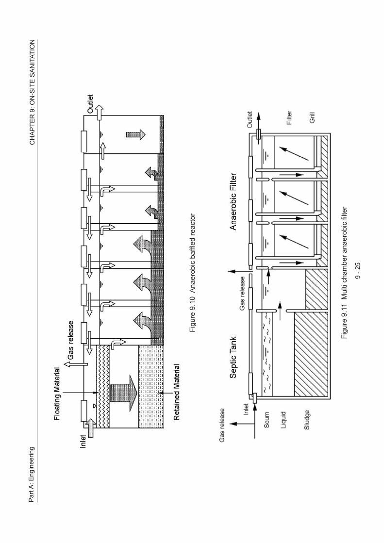
Multi-chamber septic tank system prevents sludge carryover. The schematic diagrams of anaerobic filter, anaerobic baffled reactor, and multi chamber anaerobic filter is provided in Figure 9.9, Figure 9.10 and Figure 9.11 respectively.
Simple one unit anaerobic Filter integrated in the second chamber of a septic tank. Gas is evacuated by the venting opening at the upper right.
Source: Tilley et al., 2008
Figure 9.9 Anaerobic filter
A typical septic tank up flow filter for 10 persons is shown in Figure 9.12. A typical septic tank - up flow filter evapotranspiration system is shown in Figure 9.13.
CH
AP
TER
9: O
N-S
ITE
SA
NIT
ATIO
NP
art A
: Eng
inee
ring
9 - 2
5
Figu
re 9
.11
Mul
ti ch
ambe
r ana
erob
ic fi
lter
Figu
re 9
.10
Ana
erob
ic b
affle
d re
acto
r

Par
t A: E
ngin
eerin
g C
HA
PTE
R 9
: ON
-SIT
E S
AN
ITAT
ION
9 - 2
6
Figu
re 9
.12
Typ
ical
sep
tic ta
nk u
p flo
w fi
lter f
or te
n pe
rson
s

CH
AP
TER
9: O
N-S
ITE
SA
NIT
ATIO
NP
art A
: Eng
inee
ring
9 - 2
7
Figu
re 9
.13
Sep
tic ta
nk -
Up
flow
filte
r eva
potra
nspi
ratio
n sy
stem

Part A: Engineering
9 - 28
CHAPTER 9: ON-SITE SANITATION
The arrangement shown in Figure 9.13 is septic tank followed by up flow filter. The effluent of the up flow filter normally will discharge into nearby drains and will find its way to a public water course. However in some cases even the public drain may not be available and it becomes a challenge to dispose off the up flow filter effluent. In such a case the effluent will stagnate and will lead to propagation of flies, mosquitoes etc. leading to environmental problems. This can be avoided by a raising the elevation of the pan in the toilet so that effluent comes out of the septic tank at higher than the ground level. Further this effluent will go through the up flow filter before it finally comes out as treated effluent and this will involve additional drop of the sewage level. All these have to be considered so that the final effluent from the up flow filter will come out at least 30 to 45 cm above the ground level. At this location an elevated mound of sand can be constructed as a dispersion mound and flowering small plants can be grown for evapotranspiration. This system in Figure 9.13 is one such and meant for a factory with 25 persons working for whom the septic tank volume is 4.7 cum and is met by the above specified septic tank and the volume of up flow filter at one third volume of septic tank is also met with comfortably. The dispersion trench requirement is 13 sqm. The area provided is 28 x 0.8 = 22 sqm. The maximum uplift pressure can be as high as 5 – 3 = 2 m. This is countered by stone masonry floor of 0.8 m thickness which equates to 0.8 x 2.5 = 2 m of water column. On the same lines the top of the stone masonry side walls are increased to 6 m and thus the system is safe. The inter-space between the side wall and the filter and the septic tank will be filled with excavated sand and plastered in a chamber so that rain water flows away and does not get into the structure. The stone masonry itself will be random rubble using boulders available at site with base slab 0.8 m thick and sidewalls 0.5 m thick set in cement mortar 1.5 with only pointing. Later on, when the full-fledged sewerage system becomes functional, this on-site system can be dismantled and the entire stone masonry, septic tank, up flow filter are all reusable in other construction sites to advantage, The dispersion trench functions mainly by evapotranspiration due to the button rose plantation whose roots act like a pump is the capillary action. During times of rainfall, it will be necessary, to provide a temporary cover to prevent direct rainfall over the dispersion trench by simple arrangements like a tarpaulin sheet placed around it and stone boulders kept on the edges at GL.
9.3.6 PackageSepticTank–AnaerobicFilterTypeSystem
The disadvantage of the septic tank is its low treatment efficiency (30-60% BOD and SS removal) and associated cost and space requirements for the construction of soak pit. Many situations such as presence of rocky ground, highly permeable soil and high groundwater table do not allow the construction of soak pits. In such cases, it is often a common practice to discharge effluent directly into an open drain causing surface water pollution. Another disadvantage of septic tank is its incapability to handle hydraulic shock loads, as peak flow disturbs the settling zone and causes high suspended solids in the effluent. One of the recommended solutions is the provision of anaerobic filter type system for the treatment of septic tank effluent (MoUD, 2008). Hence, package type septic tank- anaerobic filter system can be used to enhance the removals
Typically, this type of package on-site treatment system is made up of LLDPE (Linear Low Density Polyethylene) and can be installed easily in a very short time. It consists of two chambers, i.e., settling and anaerobic filter. The first chamber works as a septic tank, where settleable solids are settled down and further degraded anaerobically at the bottom zone.

Part A: Engineering
9 - 29
CHAPTER 9: ON-SITE SANITATION
Figure 9.14 Lab Scale Facility Used for Testing the flow pattern and COD removal
The second chamber consists of up flow anaerobic filter, where further removal of organic matter takes place and made up of synthetic media with specific surface area of as high as 100 m2/m3. This provides additional surfaces for the growth of organisms that purify the sewage further. There are a couple of manufacturers in the country as also many others elsewhere, but published and documented performing data are not available. All the same, the relative performance as compared to mere septic tank alone is expected to be better. Precautions to be taken are the use of media from virgin material, their specific gravity being close to water and the percent volume of packing within the reactor so that the microbes do not overgrow, bridge up and eventually choke the entire filter. However, it should be noted that this effluent would still contain pathogens and nutrients that are capable of causing public health and environmental problems and there remains the ambiguity about the technology, its feasibility and technical robustness. Such systems can be easily modified and applied to India, where localized on-site treatment systems are most desirable. Lab scale testing has been carried out at IIT Roorkee and the test facility dimensions are shown in Figure 9-14.
The COD was in the range of 472 to 600 in raw sewage, 111 to 154 mg/l in septic tank effluent and 57 to 60 mg/l in the anaerobic filter effluent. Further studies are being pursued for pilot scale testing, followed by actual field units in a school campus and in a household and evaluate the parameters of hydraulic and organic loadings, performance results of removal of BOD, COD and coliforms and engineering modifications to bring out a design and O&M manual.
9.3.7 On-sitePackageSepticTank-ContactAerationTypeSystem
Another improvement of the septic tank is to provide contact aeration tank after the septic tank. Hence, in package type septic tank - contact aeration system is developed in the line of well-established Japanese on-site treatment systems called Johkasou.

Part A: Engineering
9 - 30
CHAPTER 9: ON-SITE SANITATION
This type of package on-site treatment system is made up of LLDPE (Low Linear Density Polyethylene) and can be installed easily in a very short time. It consists of two chambers, i.e., settling and contact aeration with pall ring media.
The first chamber works as a septic tank, where settleable solids are settled down and further degraded anaerobically at the bottom zone. Second stage is high specific surface area (100 m2/m3), fixed film plastic media to retain high mass of aerobic microorganism to degrade the organic matter in the sewage aided by continuous diffusion of controlled air supply from a blower. The high specific surface area not only prevents clogging, but also provides intensive contact between the sewage and the fixed film aerobic bacteria for the fast degradation of organic matter. The treatment performance may be possible to be enhanced to 80-95% for BOD and SS removal. A possible section is illustrated in Figure 9.15.
Figure 9.15 Illustrative configuration of an integral septic tank and contact aeration unit

Part A: Engineering
9 - 31
CHAPTER 9: ON-SITE SANITATION
9.3.8 AdvancedAnaerobic-AerobicTypeOn-siteTreatmentSystem(Johkasou) There are various kinds of packaged treatment technologies. This subsection describes package type treatment plant, taking Japanese Johkasou as an example, and on-site construction type treatment plant.
9.3.8.1ClassificationofTreatmentSystems
Treatment systems are classified into various types according to capacity and performance.
i. Capacity
Treatment systems are classified into three types according to capacity: a small-scale unit is for several to more than a dozen people, who live in individual houses, a medium-scale system is for up to hundreds of people, who live in a condominium or small village and a large-scale system is for thousands of people in a large commercial building or factory.
Package-type is applied from small to large-scale systems. When unit is applied to large-scale, multiple tanks are connected. Package-type is made from plastics such as GFRP (Glass fibre reinforced plastics) or steel plates (that depends on the treatment method), so they can be manufactured in a factory.
The on-site construction type is made from RC and constructed on-site, so it looks nearly like a small-scale sewage treatment plant.
The classification according to the treatment capacity is mentioned in Table 9.9
Table 9.9 Classification according to treatment capacity (Example of Japan)

Part A: Engineering
9 - 32
CHAPTER 9: ON-SITE SANITATION
ii. Performance
Treatment processes are classified into three kinds according to performance:
1. Process that mainly removes BOD-related contaminants,
2. Process that removes BOD-related contaminants and nitrogen, and
3. Process that removes BOD-related contaminants, nitrogen, and phosphorus.
In addition, advanced treatment for better effluent quality is possible by applying membrane separator or flocculation separation or activated carbon adsorption, etc. Some package-types contain membrane separator unit in it. The classification according to the treatment performance is mentioned in Table 9.10.
Table 9.10 Classification according to treatment performance (Example of Japan)
9.3.8.2SystemConfiguration
A treatment system consists mainly of pre-treatment, main treatment, advanced treatment (if necessary), and disinfection processes.
i. Pre-treatment process
This process removes insoluble substances that are difficult to decompose biologically by means of sedimentation, floating, and screening. In the large-scale system, a flow equalizer is planned for stabilizing the biological treatment.

Part A: Engineering
9 - 33
CHAPTER 9: ON-SITE SANITATION
ii. Main treatment process
The main treatment process biologically removes BOD-related contaminants by aerobic treatment and removes nitrogen by combination of anoxic and aerobic treatment. The system employs a sedimentation tank for solid-liquid separation in most cases, but use of a membrane separator in place of the sedimentation tank makes it possible to downsize the system and to improve the quality of treated sewage further.
iii. Advanced treatment process (to be installed if necessary)
This process removes COD-related contaminants and phosphorus from the biologically treated sewage by means of flocculation sedimentation, sand filtration, activated carbon absorption, and dephosphorization.
iv. Disinfection process
This process disinfects E. coli and other bacteria to make effluent water safer.
9.3.8.3ExampleDesigninJapan
• Treatment flowchart and system configuration
Figure 9.16 shows the flowchart and configuration of a package-type treatment system based on the “anaerobic filter and contact aeration method (for BOD reduction)” as an example. This system consists of anaerobic filter, contact aeration, sedimentation, and disinfection tanks.
Figure 9.16 Treatment system based on the anaerobic filter and contact aeration method

Part A: Engineering
9 - 34
CHAPTER 9: ON-SITE SANITATION
• Outline of the system components
- Anaerobic filter tank
The main purpose of this tank is to remove solid matter that cannot be removed by biological treatment. In addition, anaerobic microorganisms adhering to the surface of the filter media submerged in this tank decompose part of BOD-related contaminants.
- Contact aeration tank
In this tank, the aerobic microorganisms are activated by the air supplied by blower and biodegradation takes place. That is, BOD-related contaminants are consumed and decomposed by the microorganisms. The contact media is installed in this tank and microorganisms are adhered on it to improve contact efficiency. Introduction of moving bed bioreactor (MBBR) contributes to reduce size of the package-type.
- Sedimentation tank
The purpose of this tank is solid-liquid separation. Supernatant and sludge contained in biologically treated sewage are separated by gravity sedimentation. Supernatant is transferred to subsequent process and the settled and separated sludge returns to the previous tank, resulting in a gradual rise in the sludge concentration of the aeration tank.
- Disinfection unit
This process disinfects E. coli and other bacteria contained in the supernatant from sedimentation tank to make effluent water safer. As the disinfectant, solid chlorine is used.
• Example specifications
Table 9.11 (overleaf) shows a package-type treatment system for 10 persons.
ii. On-site construction-type
• Treatment flowchart and system configuration
As an example of on-site construction-type treatment systems based on “the contact aeration method and the flocculation sedimentation method,” Figure 9.17 (overleaf) shows the flowchart and configuration. This system consists of a screen, a flow equalization tank, a contact aeration tank, a flocculation sedimentation tank, a disinfection unit, and a sludge treatment unit.
• Outline of the system components
- Screen
The purpose of this screen is to remove foreign matter. The screen is classified into three types according to mesh size: the coarse, fine and micro screens. A combination of them is planned according to the characteristics of sewage.

Part A: Engineering
9 - 35
CHAPTER 9: ON-SITE SANITATION
Figure 9.17 Flowchart of the contact aeration method and flocculation sedimentation method
Table 9.11 Example specifications for a package-type treatment system in Japan
(A):The daily amount of sewage per person is 200 L.

Part A: Engineering
9 - 36
CHAPTER 9: ON-SITE SANITATION
- Flow equalization tank
In the on-site small-scale treatment system, load changes due to rise or reduction in the flow rate of sewage and have a direct impact on the biological treatment function. This tank is installed before the biological reaction tank to have a stable load on it. The capacity of the flow equalization tank shall be specified according to changes in the flow rate of sewage.
- Contact aeration tank
This unit consists of contact aeration and sedimentation tanks. The former is filled with a contact media to form and put biological film on the media surface and to biologically treat the sewage by letting it come into contact with the film under aerobic conditions. The contact aeration tank is equipped with an aerator that maintains the aerobic environment, and a back washing machine that removes biota generated excessively from the contact media.
- Flocculation sedimentation tank
This tank removes COD-related contaminants and phosphorus by adding a flocculent to the sewage. The agent is classified into two types: one is an aluminium coagulant (e.g. aluminium sulphate) and the other is a ferric flocculent (e.g. polyferric sulphate). The unit consists of flow equalization, flocculation and flocculation sedimentation tanks.
- Disinfection unit
This unit disinfects the treated effluent. Solid or liquid (sodium hypochlorite) chlorine is used as the disinfectant.
- Sludge treatment unit
This unit receives and stores sludge generated in the biological reaction and flocculation sedimentation tanks. In certain circumstances, a sludge thickening or dehydrating unit may be planned. The stored sludge shall be regularly extracted and delivered to the outside. An example of designing an on-site construction-type sewage treatment system is shown in Appendix A.9.3.
9.3.8.4 Features
i. Advantages
• Since package-type treatment equipment can be fully manufactured in a factory, quality control of the product is easy and the price can be reduced due to a mass production effect.
• A treatment system for home use (5 to 10 persons) requires an area of 3 to 5 m2; that is to say, it is a compact system. Moreover, when it is installed underground, the space above can be used for several purposes such as a garage.
• This system, being a product manufactured in a factory, does not require complicated work on site during installation, so the installation time is short (about one week). Accordingly, it can improve environmental sanitation quickly.

Part A: Engineering
9 - 37
CHAPTER 9: ON-SITE SANITATION
• The treatment system requires running costs, such as electric charges and chemical expenses, and the treated water is comparable to that of conventional treatment system. In addition, planning advanced treatment can result cleaner effluent and remove nitrogen and phosphorus.
• Where membrane separator is applied, BOD contained in the effluent is reduced to less than 5 mg/l, and the treated effluent can be reused for various purposes.
• The treatment system can be constructed more cost-effectively and faster, because sewer is shorter compared with conventional system, especially in areas with low-medium population density, areas that have not been covered by sewer and individual houses or buildings.
ii. Notes on application
Keeping the performance of a treatment system high requires proper maintenance, which varies depending on the scale and treatment method of the system. Common works to achieve this are listed below. Each work requires expertise, so it is necessary to build up an implementation system, to train inspectors (vendors), and to educate users to increase their awareness of the importance of maintenance. For more information about the maintenance of treatment systems, see Part B Operation and Maintenance.
• Maintenance and inspection
Inspecting mechanical components including the blower, replenishing tanks with chemicals including disinfectants, etc.
• Water quality check
Checking the aeration tank for DO testing the quality of the discharged water, etc.
• Cleaning
Removing foreign matter from the screen and extracting generated sludge.
9.4 DECISION MAKING FOR ON-SITE TREATMENT TECHNOLOGY
9.4.1 General
Employing on-site sewage treatment technology requires an in-depth survey of requirements of the installation site, such as the volume and quality of treated sewage, the selection of a method based on the resulting data and the determination of the scale. After the determination of the basically required performance and scale, the treatment method shall be chosen in consideration of the following requirements:
i) The method shall be as simple as possible.
ii) The maintenance shall be easy.
iii) The construction and maintenance costs shall be low.

Part A: Engineering
9 - 38
CHAPTER 9: ON-SITE SANITATION
iv) The method shall contribute to environmental preservation and water quality improvement.
v) The quality characteristics of incoming sewage shall be understood.
vi) Changes in the quality and rate of incoming sewage shall be taken into consideration.
Any sewage treatment system is required to be made available always and display its function and performance, but the installer may have little knowledge about it. The selection of an appropriate treatment method requires consideration of preserving the water quality environment in receiving water bodies and fund necessary for construction and maintenance.
9.4.2 ProblemswithExistingOn-siteSystem
9.4.2.1NaturalCharacteristics
A natural condition requiring caution is weather, such as temperature changes and precipitation. In addition, it is necessary to investigate geographical features and groundwater levels.
The effect of temperature on the sewage treatment function varies depending on the type of treatment facilities, the degree of load, and the kinds of contaminants to be removed. A combination of nitrification and denitrification is susceptible to temperature changes; the reaction rate at 23ºC is 2 to 2.5 times that at 13ºC, the higher the water temperature, the higher the reaction rate. Accordingly, if this technology is applied to cold areas, it is effective to set up BOD and nitrogen loads lower than the design values.
Precipitation is one of the local characteristics. Mixing a large amount of rainwater with sewage reduces the treatment function. Particularly in a housing estate where sewage is collected and treated, it is necessary to employ an advanced construction technology in consideration of the effect of the amount of rainwater.
9.4.2.2SocialRequirements
If the treated sewage receiving water body is a source of drinking water, it is essential to employ a treatment method that can remove nitrogen and phosphorus and faecal coliforms to preserve the water source. In addition, the features of site where a sewage treatment tank is installed shall be taken into consideration. For example, a region with low population density can provide a relatively extensive site, which makes it possible to employ a treatment method featuring easy maintenance, while an urban area is obliged to use a compact treatment method. In addition, the latter case has the risk of troubling the neighbouring people with noise and offensive odour generated by the sewage treatment system.
Accordingly, it is essential to select a treatment method that does not cause such problems or to take measures to mitigate them.
The extent of maintaining a sewage treatment system has an effect on the treatment function and performance. Therefore, a small-scale system shall employ a method featuring as easy maintenance as possible. In addition, it is necessary to select an installation site in consideration of the smooth extraction, transportation, and treatment of sludge.

Part A: Engineering
9 - 39
CHAPTER 9: ON-SITE SANITATION
9.4.3 ElementsofSuccessfulProgramme
Planning an on-site system and making it successful require the following decision-making processes (Stages 1 to 5).
Stage1:Outlinesurveyofsettlementsandservices
The objective of the first stage is to gather information about the coverage and quality of existing services to clarify the key problems to be addressed and priority locations for improvement.
This investigation might be done citywide or within areas of the town that have already been earmarked for attention. The information can be obtained from (a) maps and other secondary sources; (b) from a rapid physical inspection on the ground; and (c) from informal discussion with residents.
This preparatory work does not involve systematic user consultation, which follows in Stage 2.The output includes one or more maps that show the existing sanitation infrastructure and services, and highlights areas where sanitation problems are most acute.
Stage2:TheNeedforassessmentandconsultation
Stage 2 entails a more detailed analysis of the current situation to reveal what types of improvements are needed and where they will have the most beneficial impact. It involves further technical investigations in priority areas identified from Stage 1, plus an assessment of existing services from the users’ point of view.
This should provide a fuller understanding of why existing services have failed or are otherwise inadequate. This is also an opportunity to find out what type of improvements users want and would be willing to pay for, or at least contribute towards.
Stage3:Identificationofappropriatetechnologies
The objective of this stage is to eliminate technologies that are unlikely to be viable from a technical perspective and thus, narrow the field of options. The key question for each option at this stage is: ‘Can it work?’ A variety of additional factors (some of them financial and managerial) affect whether an option would in fact be viable and these are considered in Stage 4.
Stage4:Developmentofcostoptions
Stage 3 identified technology options that are viable from a technical perspective. In order that technology choices can be made, this stage estimates the capital and operating costs associated with each option over its anticipated lifetime, and considers how the new services could be operated and maintained. This should confirm whether the technologies are viable in terms of the human and financial resources available locally.
For those that are viable, cost packages can be presented to the community in Stage 5 and agreement reached on the final choice.

Part A: Engineering
9 - 40
CHAPTER 9: ON-SITE SANITATION
Stage5:Reachingconsensusonpreferredoptions
In the final stage, the options developed in Stage 4 can be presented back to the community. For each package, the technical, managerial and financial implications - including proposed operation and maintenance arrangements - need to be explained clearly. This should enable residents to engage in an informed discussion with municipal representatives resulting, hopefully, in consensus on the way forward.
The following shows preconditions important for a successful on-site system:
• Establish and enforce clear and effective policy frameworks
- Update and enforce septic tank design codes - Mandate scheduled desludging
• Strengthen institutional and implementation capacity
- Develop comprehensive awareness programmes, especially targeting septic tank users - Develop mechanisms for inter-agency coordination and dialogue - Develop comprehensive capacity building programmes that engage educational institutions - Apply economies of scale in deploying septage services - Leverage real estate development to build sewerage infrastructure - Engage private service providers
• Increase funding for septage management
- Strengthen National financial support for septage management - Promote creative financing - Design innovative sewerage tariff structures - Develop progressive fee structures in line with willingness to pay - Create opportunities and incentives for commercial activities
9.4.4TransportandFateofSludge
Sludge resulting from on-site treatment shall be treated and disposed of in consideration of its impact on the surrounding environment. The following shows precautions for this work:
• Sludge shall not pollute the environment
• Sludge shall not produce any diseases and pests
• Sludge shall not be disposed off illegally
• Sludge shall be reused as effectively as possible.
In any case, it is recommended to effectively change the septage and sludge to compost for agricultural use or to soil conditioners in its final disposition. The septage shall be disposed as per the advisory note issued by the MoUD, http://urbanindia.nic.in/programme/uwss/Advisory_SMUI.pdf

Part A: Engineering
9 - 41
CHAPTER 9: ON-SITE SANITATION
9.5 DEALING WITH SEPTAGE
The effluent from the septic tank can be collected in a network of drains and/or sewers and treated in a treatment plant designed appropriately on the lines discussed in Chapter 5. The accumulating sludge at the bottom of the septic tank however, has to be also removed and treated once it has reached the designed depth or at the end of the designed desludging period whichever occurs earlier. Such a removal is possible only by trucks. While sucking out the sludge, the liquid in the septic tank will also be sucked out. Such a mixture is referred to as septage. Obviously, the removal of septage from a household septic tank will occur approximately once in two or three years only.
9.5.1 CharacterisationofSeptage
9.5.1.1SepticTanksusedonlyforWaterClosets
In general, the septic tank is intended to be used only for the water closet and hence, the night soil alone is the causative factor for the organic load. Thus, as far as the BOD is concerned, the per capita contribution of night soil and the volume of ablution water and its frequency per day are relevant. The urine is the factor for the nitrogen content. The septic tank system reported in the twin drain system has recorded a range of characteristics of BOD, COD and SS as in Table 9.12 and in Table 8.1.
Table 9.12 Range values of BOD, COD and SS at inlet to septic tank in India
The average amount of ablution water used at this location was about 6 litres per use. The BOD from defecation is about 8 grams/day. This corresponds to the BOD value in the above table. This value of BOD can however vary drastically based on the volume of ablution water and the number of times per day though the usage rarely exceeds one usage per day. It stands to reason to infer that the BOD of septage is relatable to the liquid portion and the suspended matter and the rates at which these have undergone some degradation by anaerobiasis in the tank and the accumulation especially in the sludge zone. All these are highly variable and as such a theoretical basis for arriving at the characteristics of septage is fraught with uncertainty. In respect of the literature values reported from advanced countries in the west, the personal habits of ablution water vs. toilet paper is a crucial influencing factor defying the flat out adoption of the characteristics reported from those locations.
9.5.1.2SepticTanksusedforallDomesticSewage
The per capita BOD being 36 g per day and a water usage at about 100 lpcd will imply a BOD of 360 mg/l though it will be higher if the lpcd goes down.

Part A: Engineering
9 - 42
CHAPTER 9: ON-SITE SANITATION
9.5.1.3SepticTanksusedforSewagefromWaterClosetsandBathing
The US EPA “Handbook on Septage Treatment and Disposal - 62568409” identifies Septage as arising from water closets and bath tubs. This is understandably off the mark for the average Indian conditions where the bath tub is first of all a non-entity in the household except in high profile urban living, where incidentally the conventional sewage prima facie eliminates the septage issue.
9.5.1.4ValuesReportedfromElsewhere
Given the above understanding of the overall scenario, it stands to reason not to be guided by the characterization data from western countries in the bath tub usage category. A value reported is “BOD concentrations between 2,000 and 20,000 mg/l and TSS values in excess of 50,000 mg/l, where septic tank effluent has values averaging 200 mg/l BOD and 300 mg/l TSS” (Septage Management Guide for Local Governments-David M Robbins). The US EPA in “Handbook on Septage Treatment and Disposal - 62568409” has reported the organic and heavy metals in septage as in Table 9-13 and Table 9-14 (overleaf). The characteristics of Septage reported from the city of Surabaya, Indonesia are BOD of 8,250 mg/l, COD of 17,250 mg/l, and TSS of 2,000 mg/l.
9.5.1.5ValuestobeconsideredforIndianConditions
Given the above wide variations in literature values and the various influencing factors, it becomes risky to hazard a guess on advocating a set of characteristics for septage in Indian conditions. However, in order to bring about an example of treatment of septage, the values in Table 9-15 (overleaf) are proposed to be advocated purely for illustration and it should be mandatory to carry out local sampling and analysis before designing the treatment and disposal system.
9.6 LOGISTICS OF SEPTAGE COLLECTION
Basically the septage collected should be treated as it cannot be let into the environment directly because of the characteristics in Table 9-15. Because of this, a treatment facility shall be set up or the septage added to an existing septage treatment facility. This implies a near uniform loading all the year round instead of peaking the discharge at certain days alone. This in turn demands the planned septage collection logistics round the year by the septage trucks. Hence the establishment of a septage collection unit becomes an adjunct to the decentralized sewerage system where septic tanks are the primary treatment at households.
9.7 SEPTAGE TREATMENT FACILITY
Sludge generated in an on-site treatment facility is regularly extracted and hygienically treated. The sludge treatment method includes (1) delivery to a sewage treatment facility and treatment with sludge generated in the sewage treatment process, (2) treatment in a special sludge treatment facility, (3) solar drying on a floor, and (4) treatment by a mobile dehydrating truck. This section describes the first and second method.
9.8 TREATMENT OF SEPTAGE IN EXISTING STP
This can be brought about in (a) existing STPs depending on the concentrations of BOD, flows and spare capacity available in them and (b) separate dedicated treatment facility for septage.

CH
AP
TER
9: O
N-S
ITE
SA
NIT
ATIO
NP
art A
: Eng
inee
ring
9 - 4
3
Tabl
e 9.
13 S
epta
ge c
hara
cter
istic
s as
per
US
EPA
Not
e:
i) V
alue
s ex
pres
sed
as m
g/L,
exc
ept f
or p
H.
ii)
The
dat
a pr
esen
ted
in th
is T
able
wer
e co
mpi
led
from
man
y so
urce
s. T
he in
cons
iste
ncy
of in
divi
dual
dat
a se
ts re
sults
in s
ome
skew
ing
of
the
dat
a an
d di
scre
panc
ies
whe
n in
divi
dual
par
amet
ers
are
com
pare
d. T
his
is ta
ken
into
acc
ount
in o
fferin
g su
gges
ted
desi
gn v
alue
s.
Sou
rce:
US
EPA

Par
t A: E
ngin
eerin
g C
HA
PTE
R 9
: ON
-SIT
E S
AN
ITAT
ION
9 - 4
4
Tabl
e 9.
14 H
eavy
met
als
in s
epta
ge a
s pe
r US
EPA
Not
e:
i) Va
lues
exp
ress
ed a
s m
g/L.
ii)
Va
lues
con
verte
d fro
m µ
g/g
assu
min
g TS
=40,
000
mg/
L.
Sou
rce:
US
EPA

Part A: Engineering
9 - 45
CHAPTER 9: ON-SITE SANITATION
Table 9.15 Illustrative characteristics of septage for Indian Conditions
9.8.1 Pre-TreatmentofSeptage
This is needed to (a) ensure a flow equalization tank for the septage flow so that it can be loaded onto the STP at as much uniform flow as possible through the 24 hours, (b) a degritting facility to segregate the grit content and prevent it from getting into aeration units and pumps etc. and (c) separate the liquid stream and sludge stream.
The equalization tank may be a relatively deeper tank equipped with sub surface mixers to maintain the contents in suspension. The surface aerators and diffused aeration will create odour problems.
The degritting facility is best designed as a vortex separator similar to the one described in Chapter 5. The sludge-liquid separation facility can be a filter press or belt press or screw press or centrifuges depending on the feed solids concentration being within the capacity of these equipment. Their designs will be the same as in Chapters 5 and 6.
The pumps however, can be submersible pump sets with open impellers. A typical receiving station facility is shown in Figure 9.18 (overleaf)
9.8.1.1Co-treatmentinExistingSTPs-LiquidStream
The basic consideration is the spare capacity at the existing STP. Normally, the septage volumes are not unduly significant in relation to the full-fledged STP volumes and would seldom exceed about say 5% and this way, even if the STP is functioning at design capacity, volume wise, it will not be a problem to add even up to 5% of flows. But it is the BOD load that comes in the way.
Considering a typical STP with about 300 mg/l of raw BOD and a septage volume of about 3% with a BOD of say 4,000 mg/l, this would result in a situation mentioned overleaf.

Part A: Engineering
9 - 46
CHAPTER 9: ON-SITE SANITATION
Figure 9.18 Typical septage receiving facility
Design capacity of the STP = 1 mld
Actual operating capacity = 0.65 mld
BOD load in to the STP = 0.65 mld × 300 mg/l = 195 kg/day
BOD load from septage = 0.03 mld × 4,000 mg/l = 120 kg/day
Total resulting BOD load = 195 + 120 = 315 kg/day
Designed ability of the STP for BOD load = 1 × 300 = 300 kg/day
Thus, it may be possible to accommodate the septage as long as the actual flow to STP does not increase. But then, over a period of time both the sewage volume and septage will increase and hence, it is not easy to use this option as a permanent measure. At the same time, if the spare capacity is available, then it is wiser to opt for this instead of rushing into a dedicated septage treatment facility. Yet another option will be to augment or upgrade the STP capacity, which is by far simpler and so far as the liquid stream is concerned.
9.8.1.2Co-treatmentinExistingSTPs-SludgeStream
The computations similar to that in respect of liquid stream shall be evaluated to verify whether the sludge treatment facilities of the existing STP can handle the extra sludge from the septage. Most often, this may be possible. In case it is not possible, add on sludge treatment standalone facilities shall be designed and constructed instead of trying to invasive augmentations of existing facilities.
9.8.1.3PointsofAdditionoftheLiquidandSludgeStreams
The points of addition of liquid and sludge streams provided spare capacities are available are suggested in Figure 9.19 (overleaf)
9.9 TREATMENT OF SEPTAGE AT INDEPENDENT SeTP
When the distance or the capacity of the plant becomes a limiting factor, it is not a feasible option to transport and treat the septage to the sewage treatment facilities.

Part A: Engineering
9 - 47
CHAPTER 9: ON-SITE SANITATION
In this case treatment plants specially meant for septage treatment becomes an attractive option. Independent septage treatment plants are designed specifically for septage treatment and usually have separate unit processes to handle both the liquid and solid portions of septage.
These facilities include mechanical dewatering, sludge drying beds, Waste stabilization ponds, etc. The benefit of using these treatment plants is that they provide a regional solution to septage man-agement. Many septage treatment plants use lime to provide both conditioning and stabilization before the septage is dewatered. Dewatered sludge can be used as organic fertilizer after drying and composting. The remaining effluent/filtrate/supernatant can be released to another treatment process such as WSP, Anaerobic baffled reactor, constructed wetland or combination of these of extended aeration activated sludge where it can undergo further treatment and then finally can be safely discharged.
Choosing an appropriate septage management method relies not only on technical aspect but also on regulatory requirements. The management option selected should be in conformity with local, State and Central regulations. Some of the factors that determine the process of selection include: land availability and site conditions, buffer zone requirements, hauling distance, fuel costs, labour costs, disposal costs and other legal and regulatory requirements.
The technical options could be as follows:
Case1:LandAreaisnotlimitedbutFundsareLimited Option-1
Pretreatment - Anaerobic Digesters - Dewatered and Dried Sludge - Composting - Reuse as Organic Fertilizer; Filtrate of Sludge Drying Bed and Digester supernatant - Pumping - Reed beds (or) Constructed wetlands - Electricity generation from digester gas. Totally nature based system with mechanical equipment as needed.
Constructed wetlands are essentially on-site technologies involving sequential treatment of sewage on-site, in selective filter media and finally greenbelt development and have been developed by IIT Powai and called Soil Bio Technology and also NEERI and called as Phytorid.
A septage treatment facility handling nearly 51 MLD at Nonthaburi in Thailand is widely reported in literature. The treatment process is shown in Figure 9.20.
It is reported that the treatment is anaerobic digestion and the digested sludge is sent to drying beds. The filtrate is dewatered in sand beds and is sent to ponds and the pond effluent is used on public parks. The use of constructed wetlands has also been reported with solids loading rate of 250 kg/m2/year, once a week application and percolate impounding for 6 days and harvesting twice a year with COD removal efficiency of 80 to 90%, and solids accumulation at 12 cm/year in the impoundment.
A photo view is presented in Figure 9.21.

Par
t A: E
ngin
eerin
g C
HA
PTE
R 9
: ON
-SIT
E S
AN
ITAT
ION
9 - 4
8
Figu
re 9
.19
Poi
nts
of li
kely
add
ition
of l
iqui
d an
d so
lids
from
sep
tage
on
to e
xist
ing
STP
s

Part A: Engineering
9 - 49
CHAPTER 9: ON-SITE SANITATION
Source:USAID, 2010Figure 9.21 A photo view of septage treatment process at Nonthaburi in Thailand
Source:USAID, 2010
Figure 9.20 Septage treatment process at Nonthaburi, Thailand
Option-2
Pretreatment - lime stabilization (optional) - Pumping - Sludge Drying beds (FRP covered in regions of high rainfall) - Dewatered & Dried Sludge - Composting - Reuse as Organic Fertilizer; Filtrate of Sludge Drying Bed - Pumping - Anaerobic Baffled Reactor / Covered Anaerobic Ponds - Facultative - Aerobic / Maturation Ponds - chlorination - discharge’
Case2:LandAreaisLimitedandFundsarealsoLimited.
Option-1
Pretreatment - lime stabilization (optional) - Pumping - Mechanical Sludge dewatering system - Dewatered sludge - Solar drying or/and Composting - Reuse as Organic Fertilizer; Filtrate of Mechanical Dewatering Machine - Pumping - Anaerobic Baffled Reactor / Covered Anaerobic Ponds - Facultative - Aerobic / Maturation Ponds - chlorination - discharge. There should be 25% additional capacity of sludge drying beds in case of maintenance of dewatering machine and or unavailability of polyelectrolyte.

Part A: Engineering
9 - 50
CHAPTER 9: ON-SITE SANITATION
Option-2
Pre-treatment - lime stabilization (optional) - Pumping - Sludge drying beds (FRP covered in regions of high rainfall) - Dewatered & Dried Sludge - Composting - Reuse as Organic Fertilizer; Filtrate of Sludge / septage Drying Bed - Pumping - Extended Aeration - Activated Sludge Process (Continuous or Batch) - chlorination - discharge
Case3.LandAreaisLimitedandFundsarenotlimited
Pretreatment - lime stabilization (optional) - Pumping - Mechanical Sludge dewatering system - Dewatered sludge - Solar drying or/and Composting - Reuse as Organic Fertilizer; Filtrate of Mechanical dewatering machines - Pumping - Extended Aeration Activated Sludge Process (Continuous or Batch) - chlorination - discharge. There should be 25% addition capacity of sludge drying beds in case of maintenance of dewatering machine and or unavailability of polyelectrolyte.
9.9.1 Pre-TreatmentofSeptage
The pre-treatment facilities discussed earlier are the same in this case also (Figure 9-18).
In addition, if possible there should be lime stabilization facility to control odour, vector and pathogen destruction. Lime stabilization involves adding and thoroughly mixing lime (alkali) with each load of septage to ensure that the pH is raised to at least 12 for at least 30 minutes.
Lime addition could be done at any of these three points:
i) To the hauler truck before the septage is pumped,
ii) To the hauler truck while the septage is being pumped, or
iii) To a septage storage tank where septage is discharged from a pumper truck is shown in Figure 9.22 (overleaf)
9.9.2 Septage Dewatering
The septage after lime dosing is pumped to screw press or any other mechanical dewatering machine. Polyelectrolyte is added to increase the dewatering efficiency of the machine.
The liquid residual / pressate / filtrate / supernatant from dewatering machine can be discharged for further biological treatment. The dewatered sludge can be send for further drying or composting prior to reuse as organic fertilizer. The typical mechanical septage dewatering system is shown in Figure 9.23 (overleaf)
Instead of Screw Press the options can be:
i) Centrifuge
ii) Belt Press
iii) Filter Press

Part A: Engineering
9 - 51
CHAPTER 9: ON-SITE SANITATION
Figure 9.23 Typical Mechanical Septage Dewatering System
Supernatant to pH neutralization and dedicated STPUnderflow to mechanical dewatering with polyelectrolyte
Figure 9.22 Lime stabilization of septage

Part A: Engineering
9 - 52
CHAPTER 9: ON-SITE SANITATION
Table 9-16 Advantages and disadvantages of septage treatment at sewage treatment plant
Table 9.17 Advantages and disadvantages of independent septage treatment facility
9.10 ADVANTAGES AND DISADVANTAGES OF THE SYSTEMS
Advantages and disadvantages of septage treatment at STPs and at independent septage treatment facility are given in Table 9.16 and Table 9.17, respectively.
9.11 COMPOSTING OF DEWATERED SEPTAGE OR SLUDGE
Another feasible option is composting where bulking agents are easily available. The humus is produced after composting that can be used as a soil conditioner. Composting is the stabilization of organic waste through aerobic biological decomposition. As described in more detail in Chapter 6, the process can be accomplished in various configurations. The different types of composting include two open-area methods: windrow and static pile composting and in-vessel mechanical composting. Operational parameters for septage composting are presented in Table 9-18 (overleaf) Compost products can be sold or given away.

Part A: Engineering
9 - 53
CHAPTER 9: ON-SITE SANITATION
Table 9.18 Operational parameters for dewatered septage composting
9.12 DEWATERED SEPTAGE SLUDGE REUSE
For dewatered septage/sludge agriculture application, it should satisfy the following criteria of Class A Biosolids of US EPA either by lime stabilization, solar drying and or composting.
• A faecal coliform density of less than 1,000 MPN/g total dry solids
• Salmonella sp. density of less than 3 MPN per 4 g of total dry solids (3 MPN/4 g TS)
Properly treated sludge can be reused to reclaim parched land by application as soil conditioner, and as a fertilizer in agriculture. Deteriorated land areas, which cannot support the plant vegetation due to lack of nutrients, soil organic matter, low pH and low water holding capacity, can be reclaimed and improved by the application of sludge.
Septage sludge has a pH buffering capacity resulting from lime addition that is beneficial in the reclamation of acidic sites, like acid mine spoils, and acidic coal refuse materials.
Sludge with a solid content of 30% or more handled with conventional end-loading equipment, and applied with agricultural manure spreaders. Liquid sludge, typically with solid content less than 6% managed and handled by normal hydraulic equipment.
Agricultural use of sludge matches best with priorities in waste management. Sewage sludge contains nutrients in considerable amounts, which can be used as discussed in Chapter 6 of the part A manual.