chapter 9 capacitors - ecourse2.ccu.edu.tw
TRANSCRIPT

Chapter 9 Capacitors
ElectronicCircuits&Electronics Shao-YuLien 1

9.1 The Basic Capacitor
• A capacitor is a passive electrical component that storeselectrical charge and has the property of capacitance
• A capacitor is constructed of two parallel conductive platesseparated by an insulating material called dielectric
• Connecting leads are attached to the parallel plates
ElectronicCircuits&Electronics Shao-YuLien 2

9.1 The Basic Capacitor
• In the neutral state, both plates of a capacitor have an equal number of free electrons
• When the capacitor is connected to a dc voltage source through a resistor, electrons are removed from plate A, and an equal number of deposited on plate B
• Electrons flow only through the connecting leads and the source. No electrons flow through the dielectric of the capacitor
• The movement of electrons ceases when the voltage across the capacitor equals the source voltage
• If the capacitor is disconnected from the source, it retains the stored charge, and still have voltage across it
ElectronicCircuits&Electronics Shao-YuLien 3

9.1 The Basic Capacitor
ElectronicCircuits&Electronics Shao-YuLien 4

9.1 The Basic Capacitor
Definition. The amount of charge that capacitor can store per unit of voltage across its plates is its capacitance, designated as C. That is, capacitance is a measurement of a capacitor’s ability to store charge
𝐶 =𝑄𝑉
– Q: Charge– V: Voltage
Q=CV
𝑉 =𝑄𝐶
ElectronicCircuits&Electronics Shao-YuLien 5

9.1 The Basic Capacitor
• The farad (F) is the basic unit of capacitance.Definition. One farad is the amount of capacitance when one coulomb of charge is stored with one volt across the plates
Example. (a) A certain capacitor stores 50 𝜇C when 10 V are applied across its plates. What is the capacitance?(b) A 2.2 𝜇F capacitor has 100 V across its plates. How much charge does it store?(c) Determine the voltage across a 100 pF capacitor that is storing2 𝜇C of charge.
ElectronicCircuits&Electronics Shao-YuLien 6

9.1 The Basic Capacitor
• (a) C=Q/V=(50 𝜇C)/(10 V)=5 𝜇F• (b) Q=CV=(2.2 𝜇F)(10 V)=220 𝜇C• (c) V=Q/C=(2 𝜇C)/(100 pF)=20 kV
ElectronicCircuits&Electronics Shao-YuLien 7

9.1 The Basic Capacitor
• How a capacitor stores energy?• A capacitor stores energy in an electric field established by the
opposite charges stored on the two plates • The energy stored in the electric field is directly related to the
size of the capacitor and to the square of the voltage
W='(CV2
ElectronicCircuits&Electronics Shao-YuLien 8
9.1 The Basic Capacitor
• Every capacitor has a limit on the amount of voltage that it can withstand across its plates
Definition. The voltage rating is the maximum dc voltage that can be applied without risk of damage to the device
• If this maximum voltage (breakdown voltage or working voltage) is exceeded, permanent damage to the capacitor can result
• The breakdown voltage of a capacitor is determined by the dielectric strength of the dielectric material used
ElectronicCircuits&Electronics Shao-YuLien 9

9.1 The Basic Capacitor
• The temperature coefficient indicates the amount and directionof a change in capacitance value with temperature– Positive temperature coefficient: capacitance increases with an increase
in temperature, or decrease with a decrease in temperature– Negative temperature coefficient: capacitance decrease with an increase
in temperature, or increase with a decrease in temperature
• Temperature coefficients typically are specified in ppm/℃
ElectronicCircuits&Electronics Shao-YuLien 10

9.1 The Basic Capacitor
• No insulating material is perfect• The dielectric of any capacitor will conduct some very small
amount of current• Thus, the charge on a capacitor will eventually leak off
• The parallel resistor Rleak represents the extremely high resistance
ElectronicCircuits&Electronics Shao-YuLien 11

9.1 The Basic Capacitor
• The following parameters are important in establishing the capacitance and the voltage rating of a capacitor
• Plate area: capacitance is directly proportional to the physical size of the plates as determined by the plate area
• Plat separation: capacitance is inversely proportional to the distance between the plates
ElectronicCircuits&Electronics Shao-YuLien 12

9.1 The Basic Capacitor
• Dielectric: capacitance is directly proportional to the dielectric constant– The measure of a material’s ability to establish an electric field is called
the dielectric constant (relative permittivity)– The dielectric constant is a ratio of the absolute permittivity of a
material 𝜀 to the absolute permittivity of a vacuum 𝜀+𝜀, =
𝜀𝜀+
– 𝜀+=8.85×10⁻¹² F/m
• An exact formula for calculating the capacitance is
𝐶 =𝐴𝜀,𝜀+𝑑
– A is in m2, d is in m, and C is in F
ElectronicCircuits&Electronics Shao-YuLien 13

9.2 Types of Capacitors
• Fixed capacitors– Mica capacitors – Ceramic capacitors– Plastic-film capacitors– Electrolytic capacitors
• Variable capacitors
ElectronicCircuits&Electronics Shao-YuLien 14

9.2 Types of Capacitors
• There are two types of mica capacitors: stacked-foil and silver-mica
• Mica capacitors are generally with capacitance values ranging from 1 pF to 0.1 𝜇F, and the voltage ratings from 100 V dc to 2500 V dc.
• The dielectric constant is typically 5
ElectronicCircuits&Electronics Shao-YuLien 15

9.2 Types of Capacitors
• The ceramic dielectrics provide very high dielectric constant(typically 1200)
ElectronicCircuits&Electronics Shao-YuLien 16

9.2 Types of Capacitors
• Most plastic-film capacitors have capacitance less than 1 𝜇F
ElectronicCircuits&Electronics Shao-YuLien 17

9.2 Types of Capacitors
• Electrolytic capacitors are polarized so that one plate is positiveand the other is negative
• These capacitors are generally used for high capacitance valuesfrom 1 𝜇F to 200,000 𝜇F
• They have very low breakdown voltage (< 350 V)
ElectronicCircuits&Electronics Shao-YuLien 18

9.2 Types of Capacitors
ElectronicCircuits&Electronics Shao-YuLien 19
• Adjustable capacitors that normally have slotted screw-type adjustments and are used for very fine adjustments in a circuit are called trimmers
• The varactor is a semiconductive device that exhibits a capacitance characteristic that is varied by changing the voltage across its terminals

9.3 Series Capacitors
Lemma. When two capacitors, with capacitances C1 and C2, are connected in series with a dc voltage source, the total capacitance is
1𝐶1
=1𝐶'+1𝐶(
CT= 343534635
Proof.• Suppose that the two capacitors are initially uncharged• When the switch is closed, the current is the same at all points in a
series circuitI=Q/t
ElectronicCircuits&Electronics Shao-YuLien 20

9.3 Series Capacitors
• In a given period of time, the same amount of charges isdeposited on the plates of both capacitors
• The total charges move through the circuit is QT=Q1=Q2ElectronicCircuits&Electronics Shao-YuLien 21

9.3 Series Capacitors
• After two capacitors have been completed charged, the current ceased
• The voltage across each capacitor areV1=Q1/C1
V2=Q2/C2
• By Kirrchhoff’s voltage law,VS=V1+V2
• Since QT=Q1=Q2=Q,𝑄𝐶1
=𝑄𝐶'+𝑄𝐶(
ElectronicCircuits&Electronics Shao-YuLien 22

9.3 Series Capacitors
• Therefore, we obtain1𝐶1
=1𝐶'+1𝐶(
• When capacitors are connected in series, the total capacitances is less than the smallest capacitance value, since the effective plate separation increases
ElectronicCircuits&Electronics Shao-YuLien 23

9.3 Series Capacitors
Example. Find the total capacitance in the following circuit
CT= 343534635
=('++9:)(<<+9:)'++9:6<<+9:
=76.7 pF
ElectronicCircuits&Electronics Shao-YuLien 24

9.3 Series Capacitors
• The formula for total capacitance for any number of capacitors in series is developed as follows
1𝐶1
=1𝐶'+1𝐶(+⋯+
1𝐶>
𝐶1 =1
1𝐶'+ 1𝐶(+⋯+ 1
𝐶>
ElectronicCircuits&Electronics Shao-YuLien 25

9.3 Series Capacitors
Example. Determine the total capacitance in the following circuit
𝐶1 ='
4?46 4?56 4?@
= '4
4ABC64
D.FBC64
G.5BC=2.30 𝜇F
ElectronicCircuits&Electronics Shao-YuLien 26

9.3 Series Capacitors
Lemma. The voltage across any individual capacitor can be determined by the following formula
𝑉H =𝐶1𝐶H
𝑉I
– Cx: any capacitor in series– Vx: voltage across Cx
• The largest-value capacitor in a series connection will have the smallest voltage across it. The smallest-value capacitor will have the largest voltage across it.
ElectronicCircuits&Electronics Shao-YuLien 27

9.3 Series Capacitors
Example. Find the voltage across each capacitors in the following circuit
• 𝐶1 ='
4?46 4?56 4?@
= '4
A.4BC64
A.DFBC64
A.55BC=0.06 𝜇F
ElectronicCircuits&Electronics Shao-YuLien 28

9.3 Series Capacitors
• The voltages are as follows
𝑉' =3J34
𝑉I =+.+KL:+.'L:
25𝑉 =15.0 V
𝑉( =3J35
𝑉I =+.+KL:+.OPL:
25𝑉 =3.19 V
𝑉< =3J3@
𝑉I =+.+KL:+.((L:
25𝑉 =6.82 V
ElectronicCircuits&Electronics Shao-YuLien 29

9.4 Parallel Capacitors
Lemma. When two capacitors, with capacitances C1 and C2, are connected in parallel with a dc voltage source, the total capacitance is
CT=C1+C2
Proof.• When the switch is closed, a total amount of charges QT move
through the circuit• Part of the total charges are stored by C1 and part by C2
ElectronicCircuits&Electronics Shao-YuLien 30

9.4 Parallel Capacitors
IT=I1+I2
QT/t=Q1/t+Q2/tQT=Q1+Q2
ElectronicCircuits&Electronics Shao-YuLien 31

9.4 Parallel Capacitors
• Since Q=CV,CTVS=C1VS+C2VS
• We therefore obtain CT=C1+C2
ElectronicCircuits&Electronics Shao-YuLien 32

9.4 Parallel Capacitors
Example. What is the total capacitance in the following circuit? What is the voltage across each capacitor?
CT=C1+C2=330 pF+220 pF=550 pF
ElectronicCircuits&Electronics Shao-YuLien 33

9.4 Parallel Capacitors
• The voltage across each capacitor in parallel is equal to thesource voltage
VS=V1=V2=5 V
ElectronicCircuits&Electronics Shao-YuLien 34

9.4 Parallel Capacitors
• The formula for total capacitance for any number of capacitors in parallel is developed as follows
CT=C1+C2+…+Cn
ElectronicCircuits&Electronics Shao-YuLien 35

9.4 Parallel Capacitors
Example. Determine CT in the following circuit
CT=C1+C2+C3+C4+C5+C6
= 0.01 𝜇F+0.022 𝜇F+0.01 𝜇F+0.047 𝜇F+0.022 𝜇F= 0.133 𝜇F
ElectronicCircuits&Electronics Shao-YuLien 36

9.5 Capacitors in DC Circuits
• A capacitor will charge when it is connected to a dc voltagesource
ElectronicCircuits&Electronics Shao-YuLien 37

9.5 Capacitors in DC Circuits
• Charging curve with percentages of the final voltage
ElectronicCircuits&Electronics Shao-YuLien 38

9.5 Capacitors in DC Circuits
• When a conductor is connected across a charged capacitor, thecapacitor will discharge
ElectronicCircuits&Electronics Shao-YuLien 39

9.5 Capacitors in DC Circuits
• Discharging curve with percentages of the initial voltage
ElectronicCircuits&Electronics Shao-YuLien 40

9.5 Capacitors in DC Circuits
• Charging of a capacitor
– Recall that V=Q/C and I=Q/t, Q=It– According to the Kirchhoff’s voltage law,
iR+'3 ∫ 𝑖 𝑑𝑡=VS ⇒ UV
UW𝑅𝐶+i=0
ElectronicCircuits&Electronics Shao-YuLien 41

9.5 Capacitors in DC Circuits
• Initial condition:At t=0, vc(0)=0• Solution of the differential equation: i(t)=C1e-t/RC
• Two rules about capacitors in dc circuits– A capacitor appears as a short to an instantaneous change in voltage– A capacitor appears as an open to constant voltage
ElectronicCircuits&Electronics Shao-YuLien 42

9.5 Capacitors in DC Circuits
• The voltage across the resistorvR(t)=i(t)R=Vse-t/RC
• The voltage across the capacitorvc(t)=VS-vR(t)=VS-Vse-t/RC
ElectronicCircuits&Electronics Shao-YuLien 43

9.5 Capacitors in DC Circuits
• Discharging of a capacitor
– According to the Kirchhoff’s voltage law,
iR+'3 ∫ 𝑖 𝑑𝑡=VS ⇒ UV
UW𝑅𝐶+i=0
ElectronicCircuits&Electronics Shao-YuLien 44

9.5 Capacitors in DC Circuits
• Initial condition:At t=0, vc(0)=V0
• Solution of the differential equation: i(t)=C1e-t/RC
ElectronicCircuits&Electronics Shao-YuLien 45

9.5 Capacitors in DC Circuits
• The voltage across the resistorvR(t)=i(t)R=-V0e-t/RC
• The voltage across the capacitorvc(t)=-vR(t)=V0e-t/RC
ElectronicCircuits&Electronics Shao-YuLien 46

9.5 Capacitors in DC Circuits
• The time constant of a series RC circuit determines the rate atwhich the capacitor charges or discharges
Definition. The RC constant is a fixed time interval that equals theproduct of the resistance and the capacitance in a series RCcircuit
𝜏=RC
ElectronicCircuits&Electronics Shao-YuLien 47

9.5 Capacitors in DC Circuits
• The general expressions for either increasing or decreasingexponential curves of the voltage are given in the followingequations for instantaneous values
v=VF+(Vi-VF)e-t/𝜏
i=IF+(Ii-IF)e-t/𝜏
• Charging from zero (Vi=0)v=VF+(Vi-VF)e-t/𝜏= VF+(0-VF)e-t/𝜏= VF(1- e-t/𝜏)
• Discharging to zero (VF=0)v=VF+(Vi-VF)e-t/𝜏= 0+(Vi-0)e-t/𝜏= Vi e-t/𝜏
ElectronicCircuits&Electronics Shao-YuLien 48

9.5 Capacitors in DC Circuits
Example. In the following circuit, determine the capacitor voltage50 𝜇 s after the switch is closed if the capacitor is initiallyuncharged.
ElectronicCircuits&Electronics Shao-YuLien 49

9.5 Capacitors in DC Circuits
• The time constant is𝜏=RC=(8.2 kΩ)(0.01 𝜇F)=82 𝜇s
• The voltage to which the capacitor is fully charged is VF=50 V,and the initial voltage is 0 V
vc=VF(1- e-t/𝜏)=(50 V)(1-e-50 𝜇s/82 𝜇s)=22.8 V
ElectronicCircuits&Electronics Shao-YuLien 50

9.5 Capacitors in DC Circuits
Example. In the following circuit, determine the capacitor voltageat the time of 6 ms after the switch is closed
ElectronicCircuits&Electronics Shao-YuLien 51

9.5 Capacitors in DC Circuits
• The time constant is𝜏=RC=(10 kΩ)(2.2 𝜇F)=22 ms
• The initial capacitor voltage is Vi=10 V,vc=Vi e-t/𝜏=(10 V)(1-e-6 ms/22 ms)=7.61 V
ElectronicCircuits&Electronics Shao-YuLien 52

9.6 Capacitors in AC Circuits
• When a capacitor is connected to a ac voltage source whose thepeak voltage is held at a constant– When the frequency increases, the current also increases– When the frequency decreases, the current also decreases
ElectronicCircuits&Electronics Shao-YuLien 53

9.6 Capacitors in AC Circuits
• An increase in the amount of current with a fixed amount ofvoltage indicates that opposition to the current has decreased
• The capacitor offers opposition to current and that opposition isinversely proportional to frequency
Definition. The opposition to sinusoidal current in a capacitor iscalled capacitive reactance• The symbol for capacitive is XC, and the unit is Ω
ElectronicCircuits&Electronics Shao-YuLien 54
9.6 Capacitors in AC Circuits
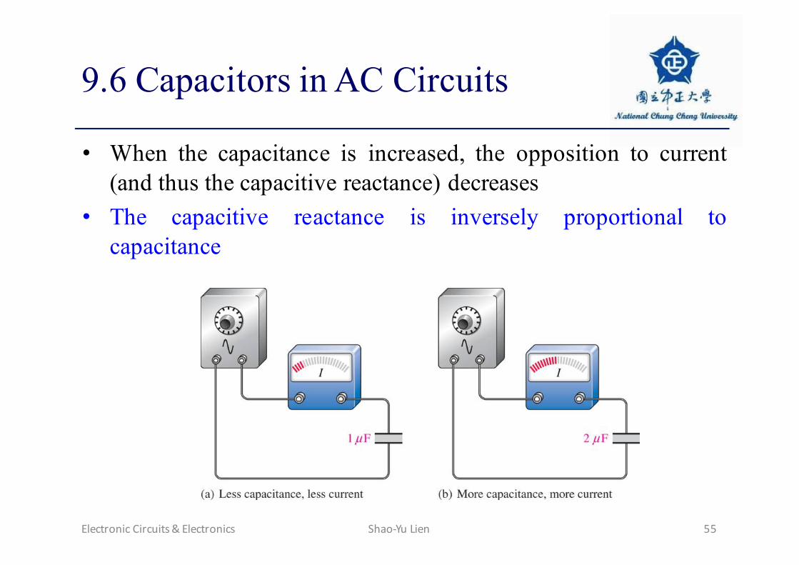
• When the capacitance is increased, the opposition to current(and thus the capacitive reactance) decreases
• The capacitive reactance is inversely proportional tocapacitance
ElectronicCircuits&Electronics Shao-YuLien 55

9.6 Capacitors in AC Circuits
• XC is proportional to 1/𝜔c
XC= '(\]3
Example. A sinusoidal voltage is applied to a capacitor. Thefrequency of the sine wave is 1.0 kHz. Determine the capacitivereactance.
ElectronicCircuits&Electronics Shao-YuLien 56

9.6 Capacitors in AC Circuits
XC= '(\]3
= '(\('.+×'+@ ^_)(+.++OP×'+`ab)
=33.9 kΩ
ElectronicCircuits&Electronics Shao-YuLien 57

9.6 Capacitors in AC Circuits
• With series capacitors, the total capacitive reactance XC(tot) isXC(tot)=XC1+XC2+…+XCn
• With parallel capacitors, the total reactance can be found by
𝑋3(WdW) =1
1𝑋3'
+ 1𝑋3(
+ ⋯+ 1𝑋3>
ElectronicCircuits&Electronics Shao-YuLien 58

9.6 Capacitors in AC Circuits
Example. What is the total capacitive reactance in each of thefollowing circuits?
ElectronicCircuits&Electronics Shao-YuLien 59

9.6 Capacitors in AC Circuits
• The reactances of the individual capacitors are the same forboth circuits
XC1= '(\]3'
= '(\(e.+f^_)(+.+'gb)
=3.18 kΩ
XC2= '(\]3(
= '(\(e.+f^_)(+.+Khgb)
=468 Ω
• In (a),XC(tot)=XC1+XC2= 3.18 kΩ+ 468 Ω=3.65 kΩ
• In (b),
𝑋3(WdW) ='
4i?4
6 4i?5
=408 Ω
ElectronicCircuits&Electronics Shao-YuLien 60
9.6 Capacitors in AC Circuits
Lemma (Ohm’s Law). The relationship between I, V, and XC is
𝐼 =𝑉𝑋3
Proof.
• Since the instantaneous current is 𝑖 𝑡 = Uk(W)UW
= 𝐶 Ul(W)UW
,current leads capacitor voltage by 90°
ElectronicCircuits&Electronics Shao-YuLien 61

9.6 Capacitors in AC Circuits
ElectronicCircuits&Electronics Shao-YuLien 62

9.6 Capacitors in AC Circuits
• In phasor notation, the above equation becomesI=j𝜔CV
𝑉𝐼=
1𝑗𝜔𝐶
= −𝑗𝑋3
• If we only emphasize on the magnitude, then
𝐼 =𝑉𝑋3
ElectronicCircuits&Electronics Shao-YuLien 63

9.6 Capacitors in AC Circuits
• For a number of capacitors in series, the voltage across a seriescapacitor is given by
𝑉H =𝐶WdW𝐶H
𝑉I
𝑉H =𝑋3p
𝑋3(WdW)𝑉I
ElectronicCircuits&Electronics Shao-YuLien 64

9.6 Capacitors in AC Circuits
Example. What is the voltage across C2 in the following circuit?
ElectronicCircuits&Electronics Shao-YuLien 65

9.6 Capacitors in AC Circuits
𝑉( =3qrq35
𝑉I=+.++hPgb+.+Khgb
10V=1.28V
𝑉( =v?5
v?(qrq)𝑉I=
OKhw<.Kefw
10V=1.28V
ElectronicCircuits&Electronics Shao-YuLien 66

9.6 Capacitors in AC Circuits
• Power in a capacitor
ElectronicCircuits&Electronics Shao-YuLien 67

9.6 Capacitors in AC Circuits
• True power (Ptrue): Ideally, all of the energy stored by acapacitor during the positive portion of the power cycle isreturned to the source during the negative. The true power iszero.
• Reactive power (Pr): The rate at which a capacitor stores orreturns energy is called its reactive power
Pr=VrmsIrms
Pr=(Vrms)2/ XC
Pr=(Irms)2 XC
ElectronicCircuits&Electronics Shao-YuLien 68