chapter 8: visual aids provided by aerodrome markings
TRANSCRIPT

Manual of Standards Part 139—Aerodromes
Chapter 8:Visual Aids Provided by Aerodrome Markings, Markers,
Signals and Signs
8-1
CHAPTER 8: VISUAL AIDS PROVIDED BY AERODROME MARKINGS, MARKERS, SIGNALS AND SIGNS
Section 8.1: General
8.1.1 Introduction 8.1.1.1 This Chapter specifies the standards for Markers, Markings, Signals and
Signs. Visual aids not conforming to these standards must not be used unless approved by CASA, in writing.
8.1.1.2 Although the specifications given here are in metric measurements, existing visual aids, which were made to Imperial measurements, may continue to be used until replacement is required for other reasons. However, new visual aids must be made and located in accordance with the metric measurements.
8.1.2 Closed Aerodrome 8.1.2.1 All Markers, Markings and Signs on a closed aerodrome or closed part of an
aerodrome, must be obscured or removed, except for unserviceability Markers or Markings, where required.
Note: A closed aerodrome or aerodrome facility means one which has been withdrawn or decommissioned, not one which is temporarily unserviceable.
8.1.3 Colours 8.1.3.1 Colours used, must conform to the Australian standard AS 2700-1996, Titled
Colour Standards for General Purposes, in accordance with the following: Table 8.1-1: Standard colours
Colour AS Colour Code AS Colour Name Blue B41 Blue Bell
Green G35 Lime Green
Orange X15 Orange
Red R13 Signal Red
Yellow Y14 Golden Yellow
White N14 White
Black N61 Black
Federal Register of Legislative Instruments F2010C00691

Chapter 8: Visual Aids Provided by Aerodrome Markings, Markers, Signals and Signs
Manual of Standards Part 139—Aerodromes
8-2
8.1.4 Visibility 8.1.4.1 Markings must be clearly visible against the background upon which they are
placed. Where required, on a surface of light colour, a contrasting black surround must be provided: on a black surface, a contrasting white surround must be provided.
8.1.4.2 Where provided, the width of surround colour must ensure an adequate visibility contrast. In the case of line markings, the width of surround on either side of the marking must not to be less than the line width.
Federal Register of Legislative Instruments F2010C00691

Manual of Standards Part 139—Aerodromes
Chapter 8:Visual Aids Provided by Aerodrome Markings, Markers,
Signals and Signs
8-3
Section 8.2: Markers
8.2.1 Introduction 8.2.1.1 Markers must be lightweight and frangible; either cones or gables. Other
forms of markers to identify extensive work areas may be used, subject to CASA agreement. When displayed, they must be secured against prop wash and jet blast, in a manner that does not cause damage to an aircraft.
8.2.1.2 Cones used as runway markers must have a height of 0.3 m and a base diameter of 0.4 m. All other cones must be 0.5 m in height, with a base diameter of 0.75 m. Cones must be painted in the following colours:
Marker Colour Runway marker white
Taxiway marker yellow
Apron edge marker yellow
Runway strip marker white
Helicopter apron edge marker blue
Unserviceability marker white, with central 25 cm red band
Runway strip marker (displaced threshold.)
split white and suitable background colour
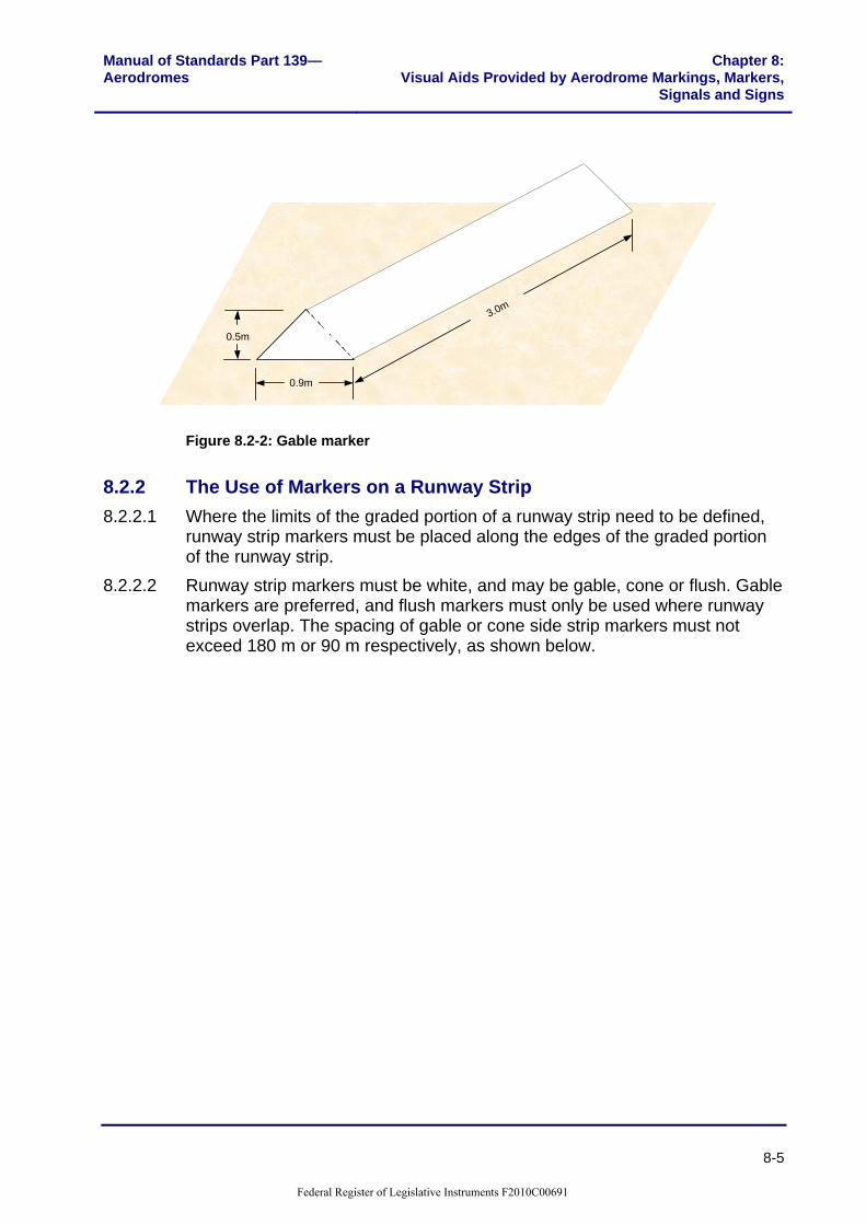
8.2.1.3 Gables must be 3 m long, 0.9 m wide, and 0.5 m high; painted white. 8.2.1.4 Fluorescent orange PVC cones or ‘witches’ hats’ approximately 0.5 m high,
may be used to convey visual information about aerodrome works to the works organisation. Witches hats must not be used to convey information to pilots about changes to the movement area. For this purpose, standard cones must be used.
Federal Register of Legislative Instruments F2010C00691

Chapter 8: Visual Aids Provided by Aerodrome Markings, Markers, Signals and Signs
Manual of Standards Part 139—Aerodromes
8-4
For cones used as runway edge markers h = 0.3m, w = 0.4m
Figure 8.2-1: Cone markers
Federal Register of Legislative Instruments F2010C00691
Manual of Standards Part 139—Aerodromes
Chapter 8:Visual Aids Provided by Aerodrome Markings, Markers,
Signals and Signs
8-5
3.0m
0.9m
0.5m
Figure 8.2-2: Gable marker
8.2.2 The Use of Markers on a Runway Strip 8.2.2.1 Where the limits of the graded portion of a runway strip need to be defined,
runway strip markers must be placed along the edges of the graded portion of the runway strip.
8.2.2.2 Runway strip markers must be white, and may be gable, cone or flush. Gable markers are preferred, and flush markers must only be used where runway strips overlap. The spacing of gable or cone side strip markers must not exceed 180 m or 90 m respectively, as shown below.
Federal Register of Legislative Instruments F2010C00691

Chapter 8: Visual Aids Provided by Aerodrome Markings, Markers, Signals and Signs
Manual of Standards Part 139—Aerodromes
8-6
180mmax
‘A’
Placing of Gable Type Markers
‘A’
90mmax
Placing of Cone Type Markers
Figure 8.2-3: Runway strip markers
Width of graded strip Dimension ‘A’ 30 m 10 m minimum
45 m 20 m minimum
60 m 20 m minimum
90 m 30 m minimum
150 m 60 m minimum
Federal Register of Legislative Instruments F2010C00691

Manual of Standards Part 139—Aerodromes
Chapter 8:Visual Aids Provided by Aerodrome Markings, Markers,
Signals and Signs
8-7
8.2.2.3 Where agreed by CASA, 200 litre (44 gallon) steel drums or tyres may be used as runway strip markers at aerodromes used by aeroplanes of not more than 9 passenger seats (See Chapter 13). Steel drums must be cut in half along their length, placed on the ground open side down. Drums and tyres must be painted white. At a certificated aerodrome, use of these markers must be noted in the Aerodrome Manual.
8.2.3 The Use of Markers on an Unsealed Runway 8.2.3.1 On unsealed runways, runway markers must be provided along both sides of
the runway where there is a lack of contrast between the runway and runway strip, and the whole of the runway strip is not maintained to normal runway grading standards. The longitudinal spacing of runway markers must not exceed 90 m.
8.2.3.2 Runway markers may be replaced by runway strip markers if the whole of the runway strip is maintained to normal runway grading standard. The thresholds must be marked either by normal threshold markings or runway cone markers in a pattern similar to that prescribed for runway strip ends.
8.2.3.3 Where an unsealed runway has a permanently displaced threshold at one end, two sets of strip markers must be provided at that end. Each set must be bi-coloured. The set associated with the permanently displaced threshold is to be painted so that the half facing the direction of approach (the first direction) appears white. The other half must be painted to match the background, and be inconspicuous to a pilot operating in the other direction (the second direction). Markers associated with the runway strip end are to appear white in the second direction and inconspicuous in the first direction.
8.2.3.4 The bi-coloured end markers associated with the displaced threshold must be cones; those associated with the runway strip end may be cones or gables.
8.2.4 The Use of Markers on an Unsealed Taxiway 8.2.4.1 Where the edges of unsealed taxiways or graded taxiway strips might not be
visually clear, taxiway edge markers must be provided to show pilots the edge of trafficable taxiways.
8.2.4.2 Where provided, the taxiway markers must be yellow cones and must be spaced to enable pilots to clearly delineate the edge of the unsealed taxiway.
8.2.5 The Use of Markers on an Unsealed Apron 8.2.5.1 Where the edges of unpaved aprons might not be visually clear to pilots,
apron edge markers must be provided. 8.2.5.2 Where provided, the apron edge markers must be yellow cones and must be
spaced to enable pilots to clearly delineate the edge of the unsealed apron area.
Federal Register of Legislative Instruments F2010C00691

Chapter 8: Visual Aids Provided by Aerodrome Markings, Markers, Signals and Signs
Manual of Standards Part 139—Aerodromes
8-8
Section 8.3: Runway Markings
8.3.1 General 8.3.1.1 Runway markings must be white on all concrete, asphalt or sealed runway
surfaces. Pre-runway-end markings must be yellow. 8.3.1.2 At runway intersections, markings of the more important runway must take
precedence over, or interrupt the markings of the other runway. At an intersection with a taxiway, the runway markings, except for runway side strip markings, must interrupt the taxiway markings.
8.3.1.3 To reduce the risk of uneven braking action, care must be taken that markings produce a non-skid surface of similar coefficient of friction to the surrounding surface.
8.3.2 Pre-runway-end Markings 8.3.2.1 Pre-runway-end markings are used where an area exceeding 60 m in length
before the runway end, has a sealed, concrete or asphalt surface, which is not suitable for normal aircraft usage.
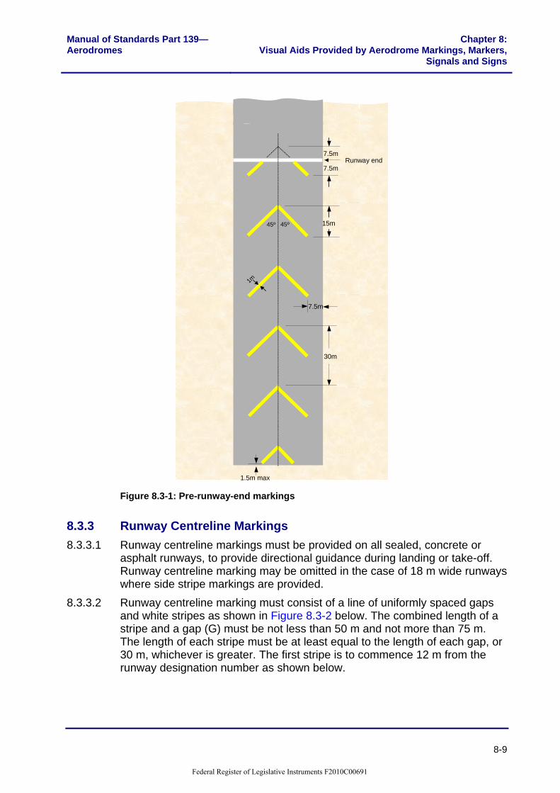
8.3.2.2 Marking must consist of yellow chevrons, spaced 30 m apart, comprising lines 0.9 m wide and angled 45 degrees to the runway centreline. The markings must terminate at the runway end marking.
8.3.2.3 This area will not normally be used for landing or take-off. If declared as a stopway, an aircraft in an abandoned take-off from the other direction may only use the area.
Federal Register of Legislative Instruments F2010C00691
Manual of Standards Part 139—Aerodromes
Chapter 8:Visual Aids Provided by Aerodrome Markings, Markers,
Signals and Signs
8-9
1.5m max
30m
15m
7.5m
7.5m
7.5mRunway end
1m
45º 45º
Figure 8.3-1: Pre-runway-end markings
8.3.3 Runway Centreline Markings 8.3.3.1 Runway centreline markings must be provided on all sealed, concrete or
asphalt runways, to provide directional guidance during landing or take-off. Runway centreline marking may be omitted in the case of 18 m wide runways where side stripe markings are provided.
8.3.3.2 Runway centreline marking must consist of a line of uniformly spaced gaps and white stripes as shown in Figure 8.3-2 below. The combined length of a stripe and a gap (G) must be not less than 50 m and not more than 75 m. The length of each stripe must be at least equal to the length of each gap, or 30 m, whichever is greater. The first stripe is to commence 12 m from the runway designation number as shown below.
Federal Register of Legislative Instruments F2010C00691

Chapter 8: Visual Aids Provided by Aerodrome Markings, Markers, Signals and Signs
Manual of Standards Part 139—Aerodromes
8-10
8.3.3.3 The width (W) of the runway centreline marking must be: (a) 0.3 m on all non-instrument runways, and instrument non-precision
approach runways where the code number is 1 or 2; (b) 0.45 m on instrument non-precision approach runways where the code
number is 3 or 4; and Category I precision approach runways; and (c) 0.9 m on Category II and Category III precision approach runways.
30
50m < G < 75m30m12m
W
Figure 8.3-2: Runway centreline markings
8.3.4 Runway Designation Markings 8.3.4.1 Runway designation markings must be provided at the thresholds of all
sealed, concrete or asphalt runways, and as far as practicable, at the thresholds of an unpaved runway.
8.3.4.2 Runway designation marking must consist of a two-digit number. The number is derived from the magnetic bearing of the runway centreline, when viewed from the direction of approach, rounded to the nearest 10 degrees.
8.3.4.3 If a bearing becomes a single digit number, a ‘0’ is to be placed before it. If a bearing becomes a three digit number, the last ‘0’ digit is to be omitted. For parallel runways, appropriate letters L (left), C (centre) or R (right) must be added to the two-digit number.
8.3.4.4 The number selected for a runway designation marking must be acceptable to CASA. When two or more runway ends have designations which may be confusing, either on the same or a nearby aerodrome, CASA will determine the designations to be used.
8.3.4.5 The shape and dimensions of the numbers and letters to be used as runway designation markings are shown in Figure 8.3-3. The location of the marking on the runway is also shown.
Federal Register of Legislative Instruments F2010C00691

Manual of Standards Part 139—Aerodromes
Chapter 8:Visual Aids Provided by Aerodrome Markings, Markers,
Signals and Signs
8-11
2805L9m
12m
9m
6m
12m
9m
Figure 8.3-3: Runway designation markings
Federal Register of Legislative Instruments F2010C00691

Chapter 8: Visual Aids Provided by Aerodrome Markings, Markers, Signals and Signs
Manual of Standards Part 139—Aerodromes
8-12
Figure 8.3-4: Shape and dimensions of runway numbers and letters
8.3.5 Runway End Markings 8.3.5.1 Runway end markings must be provided on all sealed, concrete or asphalt
runways as shown below. The marking is a white line, 1.2 m wide, extending the full width of the runway. Where the threshold is located at the end of the runway, the runway end marking will coincide with the corresponding part of the threshold marking.
Federal Register of Legislative Instruments F2010C00691

Manual of Standards Part 139—Aerodromes
Chapter 8:Visual Aids Provided by Aerodrome Markings, Markers,
Signals and Signs
8-13
Threshold
1.2m
Figure 8.3-5: Runway end marking
8.3.6 Runway Side-stripe Markings 8.3.6.1 Runway side-stripe markings must be provided at the edge of all sealed,
concrete or asphalt runways to delineate the width of the runway. Except where broken for taxiways and other runways; runway side-stripe markings must consist of one continuous white line, the same width as the runway centreline marking.
8.3.6.2 In the case of 18 m wide runways with no runway centreline marking, the width of the side-stripe marking must be 0.3 m.
8.3.6.3 The distance between outer edges of the stripes must be equal to the width of the runway. The stripes must be parallel to the runway centreline, and extend the full length of the runway, between the runway end markings.
8.3.6.4 Side-stripe markings must not extend across intersecting runways or taxiways.
8.3.6.5 For a runway with no sealed shoulders, the side-stripe markings may be omitted, if there is distinct contrast between the runway edges and the surrounding terrain.
8.3.6.6 This marking may also be used to mark the edges of a runway turning node.
Federal Register of Legislative Instruments F2010C00691

Chapter 8: Visual Aids Provided by Aerodrome Markings, Markers, Signals and Signs
Manual of Standards Part 139—Aerodromes
8-14
W
W (0.3m if centreline not marked)
Figure 8.3-6: Runway side stripe markings
8.3.7 Runway Fixed Distance Markings and Runway Touchdown Zone Markings
8.3.7.1 Runway fixed distance markings and runway touchdown zone markings must be provided at both ends of all sealed, concrete or asphalt runways 30 m wide or greater, and 1500 m long or greater.
8.3.7.2 Runway fixed distance and runway touchdown zone markings are comprised of white stripes as described and shown in Figure 8.3-7: (a) Two stripes 45 m long, each having a width (W), with inside edges
separated by a distance (D). The ends of the stripes nearest the threshold must be located 300 m from the line of the runway threshold. Dimensions W and D vary according to the runway width; W = 6 m for runways 30 m wide, and 9 m for runways 45 m wide, or greater. D = 17 m for runways 30 m wide, and 23 m for runways 45 m wide, or greater.
(b) Four stripes each 30 m long and 3 m wide, located in pairs such that the ends nearest the threshold of each pair of stripes are 150 m and 450 m respectively from the line the runway threshold. The inside edges must be separated by the distance (D).
8.3.7.3 If runway fixed distance and runway touchdown zone markings are provided on runways less than 1500 m in length, the markings at 450 m from the end of the runway threshold must be omitted.
Federal Register of Legislative Instruments F2010C00691

Manual of Standards Part 139—Aerodromes
Chapter 8:Visual Aids Provided by Aerodrome Markings, Markers,
Signals and Signs
8-15
150m 150m 150m
30m
D
30m45m
3m
W
W
D
3m
Runway touchdown zone marking
Runway fixed distance markingRunway threshold
Figure 8.3-7: Runway fixed distance and touch down zone markings
8.3.8 Runway Threshold Markings 8.3.8.1 The permanent, or permanently displaced threshold must be indicated by a
white transverse line, 1.2 m wide extending the full width of the runway at the location of the threshold, and white ‘piano key’ markings, consisting of adjacent, uniformly spaced, 30 m long stripes of specified width as shown in Figure 8.3-8.
8.3.8.2 Where practicable, this marking must also be used to indicate permanent or permanently displaced thresholds at gravel and natural surface runways.
8.3.8.3 Where the normal threshold marking is not practicable; runway markers may be used to delineate the ends of an unsealed runway.
8.3.8.4 Information on the location of thresholds is provided in Chapter 6 of this Manual.
Federal Register of Legislative Instruments F2010C00691

Chapter 8: Visual Aids Provided by Aerodrome Markings, Markers, Signals and Signs
Manual of Standards Part 139—Aerodromes
8-16
a a2a
30m
6m
12m
1
Landing direction Figure 8.3-8: Runway threshold markings
Runway width (metres)
Number of Stripes Width of Stripe Space (a) (metres)
15,18 4 1.5
23 6 1.5
30 8 1.5
45 12 1.7
60 16 1.7
Federal Register of Legislative Instruments F2010C00691

Manual of Standards Part 139—Aerodromes
Chapter 8:Visual Aids Provided by Aerodrome Markings, Markers,
Signals and Signs
8-17
8.3.9 Temporarily Displaced Threshold Markings 8.3.9.1 Whenever a permanent threshold is temporarily displaced, a new system of
visual cues must be provided, which may include provision of new markings, obscuring and alteration of existing markings, and the use of CASA approved Runway Threshold Identification Lights (RTILs).
8.3.9.2 Where a threshold is temporarily displaced less than 300 m from the end of the runway, there is no additional survey requirement for obstacles. However where this distance is exceeded, the aerodrome operator must refer the matter to CASA.
8.3.9.3 Where a permanent threshold on any runway serving international air transport operations is displaced; the location of the new threshold must be identified by the system of temporary markings specified below, and RTILs.
8.3.9.4 Where practicable, RTILs should also be used for displaced thresholds on runways not serving international air transport aircraft. When used, unless otherwise directed by the Authority, the requirements to use Vee bar markers are waived.
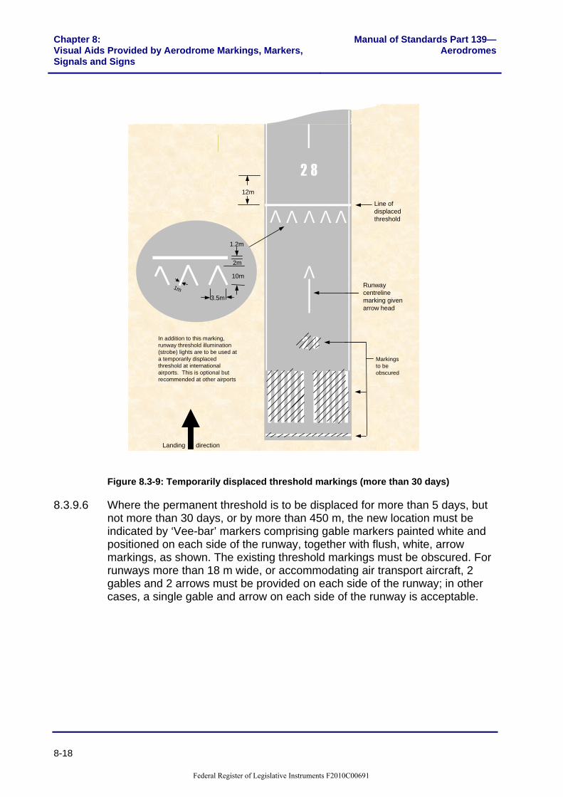
8.3.9.5 Where the permanent threshold is to be displaced for more than 30 days, the temporary threshold must comprise a white line, 1.2 m wide, across the full width of the runway at the line of the threshold, together with adjacent 10 m long arrowheads, comprising white lines 1 m wide. The number of 10m long arrowhead markings used should be commensurate with the width of the runway. The existing centreline markings between the two thresholds must be converted to arrows as shown below; the permanent threshold marking and associated runway designation number must be obscured and a temporary runway designation number provided 12 m beyond the new threshold.
Note: Where the runway fixed distance and touch down zone markings can cause confusion with the new threshold location those markings may also be obscured.
Federal Register of Legislative Instruments F2010C00691
Chapter 8: Visual Aids Provided by Aerodrome Markings, Markers, Signals and Signs
Manual of Standards Part 139—Aerodromes
8-18
V VVVV
V
2 812m
82Markings to be obscured
Runway centreline marking given arrow head
Line of displaced threshold
1.2m
10m
2m
3.5m
1m
In addition to this marking, runway threshold illumination (strobe) lights are to be used at a temporarily displaced threshold at international airports. This is optional but recommended at other airports
Landing direction
Figure 8.3-9: Temporarily displaced threshold markings (more than 30 days)
8.3.9.6 Where the permanent threshold is to be displaced for more than 5 days, but not more than 30 days, or by more than 450 m, the new location must be indicated by ‘Vee-bar’ markers comprising gable markers painted white and positioned on each side of the runway, together with flush, white, arrow markings, as shown. The existing threshold markings must be obscured. For runways more than 18 m wide, or accommodating air transport aircraft, 2 gables and 2 arrows must be provided on each side of the runway; in other cases, a single gable and arrow on each side of the runway is acceptable.
Federal Register of Legislative Instruments F2010C00691

Manual of Standards Part 139—Aerodromes
Chapter 8:Visual Aids Provided by Aerodrome Markings, Markers,
Signals and Signs
8-19
V V
12m
6m
2m
0.9m6m3m
4.25m 3.5m
12m3m 0.9m
2.5m
4m3.5m 3m 4m
Width of runway more than 18m
Width of runway 18m or less
Figure 8.3-10: Temporarily displaced threshold markings (less than 30 days)
8.3.9.7 Where a threshold is to be temporarily displaced for 5 days or less, and the displacement is less than 450 m, the new threshold location must be indicated by the same ‘Vee-bar’ markers but the permanent threshold markings may be retained.
8.3.9.8 Where a threshold at an air traffic controlled aerodrome is to be temporarily displaced for 5 days or less, and the displacement is more than 450 m, the new threshold location is to be indicated by the above markings but the permanent threshold markings may be retained.
8.3.9.9 Markings of typical threshold and displaced thresholds are illustrated in the following six figures.
Federal Register of Legislative Instruments F2010C00691
Chapter 8: Visual Aids Provided by Aerodrome Markings, Markers, Signals and Signs
Manual of Standards Part 139—Aerodromes
8-20
Clear approach surface
60m
Thre
shol
d
Commencement of LDA and TODA
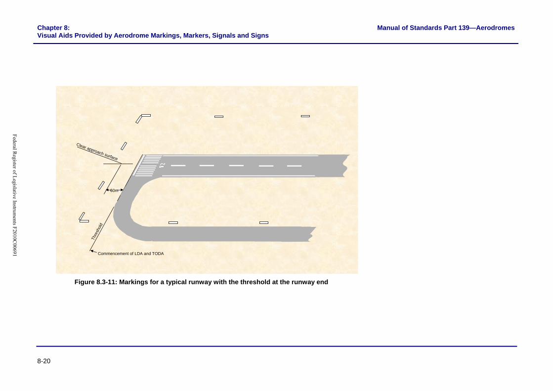
Figure 8.3-11: Markings for a typical runway with the threshold at the runway end
Federal Register of L
egislative Instruments F2010C
00691

Manual of Standards Part 139—Aerodromes Chapter 8: Visual Aids Provided by Aerodrome Markings, Markers, Signals and Signs
8-21
Runway threshold marking
Commencement of LDA
Thre
shol
d
60m
This section of runway available for all operations except landing in direction indicated
Clear approach surface
Permanent obstacle
Commencement of TODA
Figure 8.3-12: Markings for a typical runway with a permanently displaced threshold
Federal Register of L
egislative Instruments F2010C
00691

Chapter 8: Visual Aids Provided by Aerodrome Markings, Markers, Signals and Signs
Manual of Standards Part 139—Aerodromes
8-22
Temporarily displaced threshold marking (white)
Temporarily relocated runway designation marking (white)
Commencement of LDA
Commencement of TODA
Thre
shol
d
60m
Clear approach surface
Piano key and runway designation number marking obliterated
Arrows leading to displaced threshold (white)
Figure 8.3-13: Markings for a temporarily displaced threshold due to obstacle infringement of the approach surface for a period in excess of 30 days
Federal Register of L
egislative Instruments F2010C
00691

Manual of Standards Part 139—Aerodromes Chapter 8: Visual Aids Provided by Aerodrome Markings, Markers, Signals and Signs
8-23
Temporarily displaced threshold marking (white)
Thre
shol
d
Commencement of LDACommencement of TODA
Min 60m
Arrows leading to displaced threshold (white)
Works area
Unserviceability markers Temporarily relocated runway designation marking (white)
Unserviceability markers (white and red)
Work limit markers (orange)
Piano key, runway designation number and portion of runway edge marking obliterated
Figure 8.3-14: Markings for a temporarily displaced threshold due to works on the runway for a period in excess of 30 days
Federal Register of L
egislative Instruments F2010C
00691

Chapter 8: Visual Aids Provided by Aerodrome Markings, Markers, Signals and Signs
Manual of Standards Part 139—Aerodromes
8-24
Commencement of TODA
Commencement of LDA
Thre
shol
d
60m
Clear approach surface
Temporarily displaced threshold markers (white)
Note: Where the width of runway is 18m or less, a single VEE need only be provided on each side of the runway
Note: Piano keys and runway designation number markings must be obliterated unless:(a) Runway threshold identification lights are provided, or(b) Displacement is for 5 days or less
Figure 8.3-15: Markings for a temporarily displaced threshold due to obstacle infringement of approach surface for a period of 5 days or less and a displacement of less than 450 m
Federal Register of L
egislative Instruments F2010C
00691

Manual of Standards Part 139—Aerodromes Chapter 8: Visual Aids Provided by Aerodrome Markings, Markers, Signals and Signs
8-25
Temporarily displaced threshold markers (white)
Commencement of LDA
Commencement of TODA Th
resh
old
Min 60mWorks area
Unserviceability markers (white and red)Work limit markers
(orange)
Note: Piano keys and runway designation number markings must be obliterated unless:(a) Runway threshold identification lights are provided; or(b) Displacement is for 5 days or less
Unserviceability markers
Figure 8.3-16: Markings for a temporarily displaced threshold due to works in progress on runway for a period of 5 days or less and a displacement of less than 450 m
Federal Register of L
egislative Instruments F2010C
00691
Manual of Standards Part 139—Aerodromes
Chapter 8:Visual Aids Provided by Aerodrome Markings, Markers,
Signals and Signs
8-26
8.3.10 Runway Land and Hold Short Position Markings 8.3.10.1 At an aerodrome where land and hold short operations are conducted, a
runway land and hold short position marking must be provided at the intersection of two paved runways. The marking must be located and painted in accordance with the runway holding position marking specified in Paragraph 8.4.3.
Federal Register of Legislative Instruments F2010C00691

Manual of Standards Part 139—Aerodromes
Chapter 8:Visual Aids Provided by Aerodrome Markings, Markers,
Signals and Signs
8-27
Section 8.4: Taxiway Markings
8.4.1 Introduction 8.4.1.1 Taxiway markings must be provided on all asphalt, sealed or concrete
taxiways, as specified below. Taxiway markings must be painted yellow.
8.4.2 Taxi Guideline Markings 8.4.2.1 Taxi guideline markings must be provided on all asphalt, sealed or concrete
taxiway surfaces, in the form of a continuous yellow line 0.15 m wide. On straight sections, the guideline must be located in the centre of the taxiway. On curved taxiways, the guideline must be located parallel to the outer edge of the pavement and at a distance of half of the taxiway width from it; i.e. the effect of any fillet widening at the inner edge of a curve is ignored. Where a taxi guideline marking is interrupted by another marking such as a taxi-holding position marking, a gap of 0.9 m must be provided between the taxi guideline marking and any other marking.
8.4.2.2 The same form of taxi guideline marking must be used on aprons as detailed below, under ‘Apron Markings’.
8.4.2.3 Taxi guidelines on runways must not merge with the runway centreline, but run parallel to the runway centreline for a distance (D), not less than 60 m beyond the point of tangency where the runway code number is 3 or 4 and 30 m where the code number is 1 or 2. The taxi guideline marking must be offset from the runway centreline marking on the taxiway side, and be 0.9 m from the runway centrelines of the respective markings.
Note: Markings with non-compliant separations do not have to be brought into compliance until the next remarking of the pavement.
DD
0.15m
0.9mYellow
Figure 8.4-1: Taxi guideline markings meeting runway centreline markings
Federal Register of Legislative Instruments F2010C00691

Manual of Standards Part 139—Aerodromes
Chapter 8:Visual Aids Provided by Aerodrome Markings, Markers,
Signals and Signs
8-28
8.4.3 Runway Holding Position Markings 8.4.3.1 Runway holding position markings must be provided on all asphalt, sealed or
concrete taxiways wherever these join or intersect with a runway. Standards for the location of runway holding positions are specified in Chapter 6.
8.4.3.2 Runway holding positions must be marked using the Pattern A or Pattern B runway holding position markings, shown in Figure 8.4-2, as appropriate.
8.4.3.3 Pattern A marking must be used at an intersection of a taxiway and a non-instrument, non-precision approach or precision approach Category I runway, and precision approach Category II or III runway where only one runway holding position is marked. Pattern A must also be used to mark a runway/runway intersection, where one of the runways is used as part of a standard taxi route.
8.4.3.4 Pattern B marking must be used where two or three runway holding positions are provided at an intersection of a taxiway with a precision approach runway. The marking closest to the runway must be the Pattern A marking; the marking(s) further from the runway must be Pattern B.
1.0m1.0m
PATTERN A
PATTERN B
3.0m
0.3m
0.3m
0.3m
0.6m
0.3m
0.3m
Yellow Direction Towards Runway
4 lines and 3 spaces each 0.15m wide
Figure 8.4-2: Pattern A and Pattern B runway-holding position markings
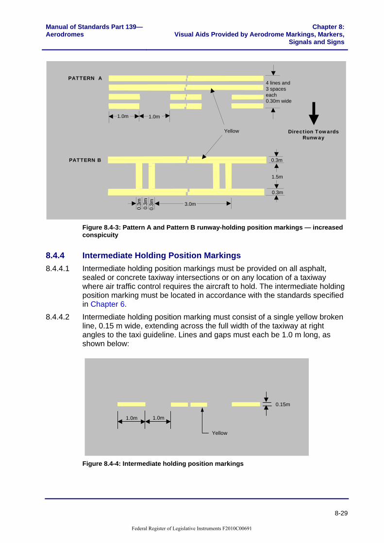
8.4.3.5 Where increased conspicuity of the Pattern A and Pattern B runway-holding position markings is required, the runway-holding position markings must be increased in size as indicated in Figure 8.4-3.
Federal Register of Legislative Instruments F2010C00691
Manual of Standards Part 139—Aerodromes
Chapter 8:Visual Aids Provided by Aerodrome Markings, Markers,
Signals and Signs
8-29
1.0m1.0m
PATTERN A
PATTERN B
3.0m
0.3m
0.3m
0.3m
1.5m
0.3m
0.3m
Yellow Direction Towards Runway
4 lines and 3 spaces each 0.30m wide
Figure 8.4-3: Pattern A and Pattern B runway-holding position markings — increased conspicuity
8.4.4 Intermediate Holding Position Markings 8.4.4.1 Intermediate holding position markings must be provided on all asphalt,
sealed or concrete taxiway intersections or on any location of a taxiway where air traffic control requires the aircraft to hold. The intermediate holding position marking must be located in accordance with the standards specified in Chapter 6.
8.4.4.2 Intermediate holding position marking must consist of a single yellow broken line, 0.15 m wide, extending across the full width of the taxiway at right angles to the taxi guideline. Lines and gaps must each be 1.0 m long, as shown below:
1.0m1.0m
0.15m
Yellow
Figure 8.4-4: Intermediate holding position markings
Federal Register of Legislative Instruments F2010C00691

Manual of Standards Part 139—Aerodromes
Chapter 8:Visual Aids Provided by Aerodrome Markings, Markers,
Signals and Signs
8-30
8.4.5 Taxiway Edge Markings 8.4.5.1 Taxiway edge markings must be provided for paved taxiways where the
edges of full strength pavement are not otherwise visually clear. Markings must consist of two continuous 0.15 m wide yellow lines, spaced 0.15 m apart and located at the taxiway edge, as shown below.
0.45m0.15m
Yellow
Yellow
Figure 8.4-5: Taxiway edge markings
Note: Whilst not mandatory, the additional provision of transverse or herringbone stripes on the sub strength surface has been found to be of assistance in avoiding the possibility for confusion on which side of the edge marking the sub strength pavement is located. This additional marking is an acceptable means of compliance with these standards.
8.4.6 Holding Bay Markings 8.4.6.1 Holding bay markings must be provided on all sealed, asphalt or concrete
holding bays. Holding bay markings must comprise taxi guideline markings and intermediate holding position markings as shown in Figure 8.4-6. Markings must be located so that aircraft using the holding bay are cleared by aircraft on the associated taxiway by at least the distance specified in Chapter 6. The holding position marking must be painted in accordance with the intermediate holding position marking, unless that is also a runway holding position, in which case the Pattern A runway holding position marking applies.
Federal Register of Legislative Instruments F2010C00691

Manual of Standards Part 139—Aerodromes
Chapter 8:Visual Aids Provided by Aerodrome Markings, Markers,
Signals and Signs
8-31
Taxiway
Holding Position
Direction of travel
Figure 8.4-6: Holding bay markings
8.4.7 Taxiway Pavement Strength Limit Markings 8.4.7.1 These markings are used at the entrance of a taxiway of low strength
pavement where the aerodrome operator decides to impose a weight limitation, for example, ‘Max 5,700 kg’.
8.4.7.2 Where the taxiway pavement strength limit marking is provided, as shown in Figure 8.4-7, the letters and numbers must be painted yellow, must be 2.0 m in height, 0.75 m in width, with 0.15 m line width and at 0.5 m spaces. The marking must be readable from aircraft on the full strength pavement.
MAX 5700KG
Full strength runway or taxiway
Taxiway
Yellow
Notes: 1 Used if desired to limit weightof aircraft using a taxiway
2 Must be readable from aircrafton full strength pavement
Figure 8.4-7: Taxiway pavement-strength limit markings
8.4.7.3 Edge markings of the associated main taxiway or apron, or the side stripe markings of the runway, must be interrupted across the width of the low strength taxiway entrance.
Federal Register of Legislative Instruments F2010C00691

Manual of Standards Part 139—Aerodromes
Chapter 8:Visual Aids Provided by Aerodrome Markings, Markers,
Signals and Signs
8-32
Section 8.5: Apron Markings
8.5.1 Introduction 8.5.1.1 Aprons accommodating aircraft of 5,700 kg Maximum All Up Mass (MAUM)
and above, must be provided with taxi guidelines and primary aircraft parking position markings. Where the apron may be occupied by these and lighter aircraft at the same time, the aerodrome operator must also provide secondary aircraft parking position markings on the apron for the lighter aircraft.
8.5.1.2 Where aprons accommodate only aircraft of less than 5,700 kg MAUM, there is no mandatory requirement for taxi guidelines nor for marked aircraft parking positions. In these cases, the aerodrome operator may decide whether to provide markings, or to allow random parking.
8.5.1.3 The design of apron markings must ensure that all relevant clearance standards are met, so that safe manoeuvring and the precise positioning of aircraft is achieved. Care must be taken, to avoid overlapping markings.
8.5.2 Apron Taxi Guideline Markings 8.5.2.1 Apron taxi guideline markings must be of the same form as those used on
the taxiway. The design of taxi guidelines on aprons is dependent on whether the aircraft is being directed by a marshaller or the pilot.
8.5.2.2 Where aircraft are to be directed by a marshaller, the ‘nose wheel position principle’ shall apply; that is, the taxi guideline is designed so that when the aircraft nose wheel follows the taxi guideline, all the required clearances are met.
8.5.2.3 Where aircraft are to be guided by the pilot, the ‘cockpit position principle’ shall apply; that is the taxi guideline is designed so that when a point on the centreline of the aircraft midway between the pilot and the co-pilot seats (or in the case of a single pilot aircraft, in the centre of the pilot seat) follows the taxi guideline, all the required clearances are met.
8.5.2.4 Where there is a change in aircraft position control between the pilot and the marshaller, the taxi guideline must convert from one principle to the other. At aerobridges, the taxi guideline must be designed using the cockpit position principle.
8.5.2.5 Where an aircraft designator marking is required to cover a multiple number of aircraft types, and there is insufficient space for the marking, an abbreviated version of the designator may be used e.g. an A330-200 may be abbreviated to A332, a BAe 146-200 to B462 and a B737-800 to B738. A list of typical aircraft designators is published by Airservices Australia on their web page: http://www.airservicesaustralia.com/pilotcentre/SpecialpilotOps/acft.pdf.
Federal Register of Legislative Instruments F2010C00691

Manual of Standards Part 139—Aerodromes
Chapter 8:Visual Aids Provided by Aerodrome Markings, Markers,
Signals and Signs
8-33
8.5.3 Apron Edge Markings 8.5.3.1 Must be provided where the limit of high strength pavement cannot be
distinguished from the surrounding area, and aircraft parking is not restricted to fixed parking positions. Where marking is required, the apron edge must be identified by 2 continuous yellow lines 0.15 m wide, spaced 0.15 m apart.
8.5.3.2 The edge of gravel, grass or other natural surface aprons must be identified by cones, spaced at a maximum distance of 60 m and painted yellow; except for dedicated helicopter aprons which must be light blue.
8.5.4 Parking Clearance Line 8.5.4.1 Parking clearance lines may be provided at an aircraft parking position to
depict the area that must remain free of personnel, vehicles and equipment when an aircraft is taxiing (or being towed) into position or has started engines in preparation for departure.
8.5.4.2 Parking clearance lines may also be provided on light aircraft aprons with random parking, where it is desired to limit the parking to particular areas.
8.5.4.3 The parking clearance line must comprise a continuous red line 0.10 m or, if desired, 0.20 m wide. Where required, a continuous yellow or white line 0.10 m wide on either side can enhance the parking clearance line. The words ‘PARKING CLEARANCE’ must be painted in yellow on the side where the light aircraft are parked, and readable from that side. These words must be repeated at intervals not exceeding 50 m, using letters 0.3 m high, located 0.15 m from the line, as shown below.
PARKING CLEARANCE
0.3m
0.15m
0.3m0.1m/0.2m
Yellow / White
Yellow
Red
Figure 8.5-1: Parking clearance line
8.5.5 Aircraft Type Limit Line 8.5.5.1 Where adjoining portions of pavement cannot accommodate the same
aircraft type, information to this effect must be provided, marking the
Federal Register of Legislative Instruments F2010C00691

Manual of Standards Part 139—Aerodromes
Chapter 8:Visual Aids Provided by Aerodrome Markings, Markers,
Signals and Signs
8-34
boundary of the restricted pavement. The marking must consist of a broken yellow line, comprising strips 3 m long and 0.3 m wide, separated by 1 m spaces. The designator must be 0.15 m above the line, in letters and numbers 0.5 m high. The marking is to be repeated at intervals not exceeding 50 m.
NO B7270.3m
0.15m
3.0m1.0m
0.5m
Yellow
Yellow
Figure 8.5-2: Aircraft type limit line
8.5.6 Parking Weight Limit Line 8.5.6.1 Where adjoining portions of pavement cannot accommodate the same
aircraft weight, this must be signified by marking an aircraft weight limitation on the weaker pavement. The marking must consist of a broken yellow line, comprising strips 3 m long and 0.3 m wide, separated by 1 m spaces. The designator must be 0.15 m above the line, in letters and numbers 0.5 m high. The marking is to be repeated at intervals not exceeding 50 m.
MAX 9000 KG0.3m
0.5m
0.15m
3.0m1.0m
Yellow
Yellow
Figure 8.5-3: Parking weight limit line
Federal Register of Legislative Instruments F2010C00691

Manual of Standards Part 139—Aerodromes
Chapter 8:Visual Aids Provided by Aerodrome Markings, Markers,
Signals and Signs
8-35
8.5.7 Leased Area Line 8.5.7.1 Where the aerodrome operator wishes to identify leased areas on a sealed,
concrete or asphalt apron, the marking must consist of a 0.15 m solid line, painted lime green.
8.5.8 Equipment Clearance Line 8.5.8.1 Equipment clearance lines must be used on congested aprons to assist
service vehicles keep clear of manoeuvring aircraft. This marking must consist of red stripes, 1 m long and 0.15 m wide, separated by 1 m gaps. The designation ‘EQUIPMENT CLEARANCE’ must be painted on the side of the line occupied by the equipment and readable from that side. The designation must be repeated along the line at intervals of not more than 30 m. Letters must be 0.3 m high, 0.15 m from the line, painted red.
1.0m 1.0m
0.3m0.15m
0.15m
EQUIPMENT CLEARANCE
Red
Figure 8.5-4: Equipment clearance line
8.5.9 Equipment Storage Markings 8.5.9.1 Equipment storage markings must consist of a continuous red painted line,
0.1 m wide. 8.5.9.2 The words ‘EQUIPMENT STORAGE’ must be painted in red on the side
where equipment is stored, and readable from that side. Letters must be 0.3 m high and 0.15 m from the line, as shown below. This marking must be repeated at intervals not exceeding 50 m along the boundary.
Federal Register of Legislative Instruments F2010C00691

Manual of Standards Part 139—Aerodromes
Chapter 8:Visual Aids Provided by Aerodrome Markings, Markers,
Signals and Signs
8-36
0.10m
EQUIPMENT STORAGE
0.15m
0.3m
Red
Red
Figure 8.5-5: Equipment storage and apron road marking
8.5.10 Apron Service Road Markings 8.5.10.1 Roads on apron areas must be marked to keep vehicle traffic clear of aircraft
and taxiways, and to minimise the risk of vehicle-to-vehicle accidents. 8.5.10.2 Each lane of an apron service road must be of a minimum width to
accommodate the widest vehicle in use at that location, e.g. emergency vehicles or ground support equipment.
8.5.10.3 The apron service road marking must consist of a continuous white painted line, 0.1 m wide.
Federal Register of Legislative Instruments F2010C00691

Manual of Standards Part 139—Aerodromes
Chapter 8:Visual Aids Provided by Aerodrome Markings, Markers,
Signals and Signs
8-37
road
0.10m0.10m
Figure 8.5-6: Apron service road
8.5.10.4 Where a service road is located adjacent to taxiing aircraft the side marking must be shown with a continuous double white line. This indicates DO NOT CROSS. Each continuous white line must be 0.1 m wide. The separation between the two continuous white lines must not be less than 0.05 m.
Federal Register of Legislative Instruments F2010C00691
Manual of Standards Part 139—Aerodromes
Chapter 8:Visual Aids Provided by Aerodrome Markings, Markers,
Signals and Signs
8-38
road
0.10m0.10m0.05m
Veh i
cle
limi t
line
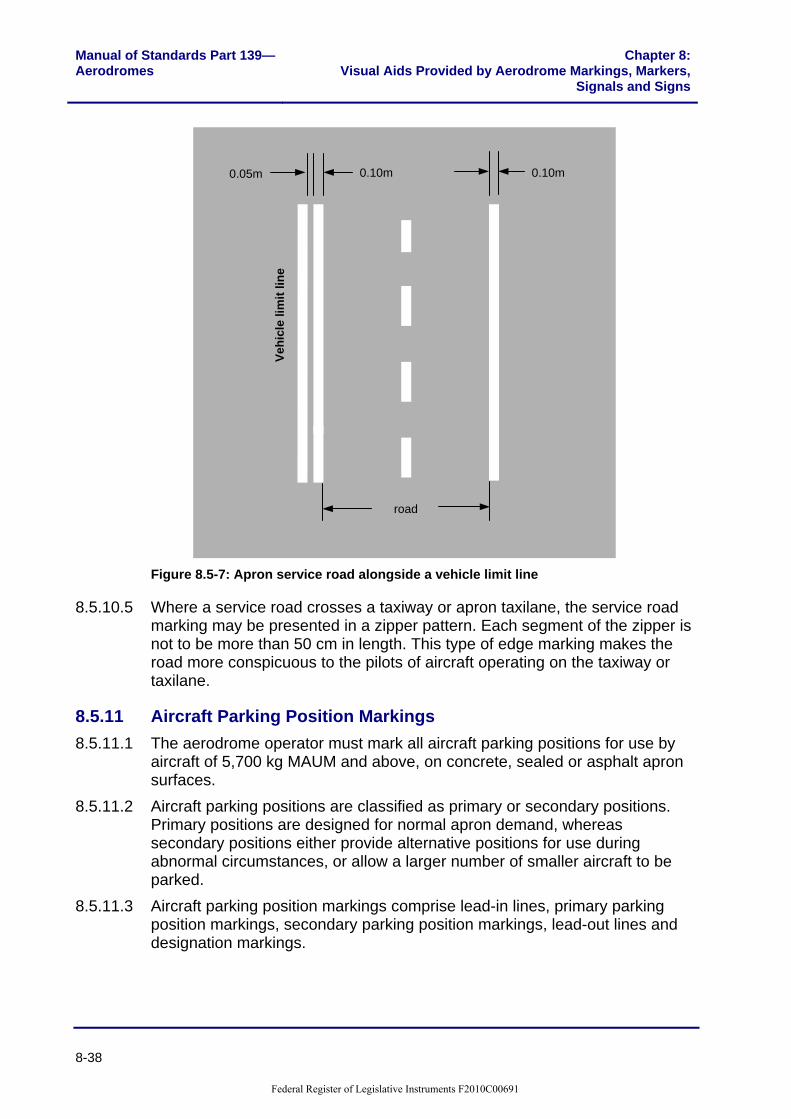
Figure 8.5-7: Apron service road alongside a vehicle limit line
8.5.10.5 Where a service road crosses a taxiway or apron taxilane, the service road marking may be presented in a zipper pattern. Each segment of the zipper is not to be more than 50 cm in length. This type of edge marking makes the road more conspicuous to the pilots of aircraft operating on the taxiway or taxilane.
8.5.11 Aircraft Parking Position Markings 8.5.11.1 The aerodrome operator must mark all aircraft parking positions for use by
aircraft of 5,700 kg MAUM and above, on concrete, sealed or asphalt apron surfaces.
8.5.11.2 Aircraft parking positions are classified as primary or secondary positions. Primary positions are designed for normal apron demand, whereas secondary positions either provide alternative positions for use during abnormal circumstances, or allow a larger number of smaller aircraft to be parked.
8.5.11.3 Aircraft parking position markings comprise lead-in lines, primary parking position markings, secondary parking position markings, lead-out lines and designation markings.
Federal Register of Legislative Instruments F2010C00691

Manual of Standards Part 139—Aerodromes
Chapter 8:Visual Aids Provided by Aerodrome Markings, Markers,
Signals and Signs
8-39
8.5.12 Lead-in Line 8.5.12.1 Lead-in lines must be provided to each aircraft parking position on all sealed,
concrete and asphalt aprons with aircraft parking position markings. 8.5.12.2 Lead-in lines to primary aircraft parking positions must be continuous, 0.15 m
wide and painted yellow; they have the same characteristics as a taxi guideline.
8.5.12.3 At a secondary parking position, the lead-in line must be marked by a series of solid yellow circles 0.15 m in diameter, spaced at 1 m intervals. Where an abrupt change in direction occurs the line must be solid for a distance of 2 m before and after the turn.
8.5.13 Taxi Lead-in Line Designation 8.5.13.1 Designation must be provided where an apron has more than one marked
aircraft parking position. Taxi lead-in line designation markings must be located at the beginning of each diverging taxi guideline or lead-in line; aligned so that they can be seen by the pilot of an approaching taxiing aircraft. There are three types of taxi lead-in line designations: (a) parking position number designation; (b) aircraft type limit designation; and (c) aircraft weight limit designation.
8.5.13.2 The parking position number designation indicates the aircraft parking position to which the line leads. Where a lead-in line leads to several positions, the designation must include the first and last numbers of the positions served. For instance, a guideline leading to the six positions numbers 1 to 6, is shown as 1–6. The designations must comprise characters 2 m high, painted yellow, as shown in Figure 8.5-8.
Pilot position
727
6A
0.3m 2m 2m1m
Note: Other designators could be
‘H ONLY’ (helicopters only)
‘F27 ONLY’ or ‘NO B727’
YellowYellow YellowYellow
Figure 8.5-8: Parking position number designation
Federal Register of Legislative Instruments F2010C00691

Manual of Standards Part 139—Aerodromes
Chapter 8:Visual Aids Provided by Aerodrome Markings, Markers,
Signals and Signs
8-40
8.5.13.3 The aircraft type limit designations indicate which parking positions are capable of accommodating particular aircraft types. The designation must be painted in yellow characters 2 m high, with 0.3 m spacing from the lead-in line, as shown in Figure 8.5-9. Appropriate aircraft type limit designations must be provided at the lead-in line for each position to which restrictions apply. Where a diverging lead-in line leads to an apron parking position suitable only for helicopters; the designation ‘H ONLY’ must be provided.
6A1-
6
Yellow
Pilot position
0.3m2m
0.15m
0.3m
Yellow
Figure 8.5-9: Aircraft type limit designation
8.5.13.4 The aircraft weight limit designations inform pilots of a weight limitation to a
parking position. They specify the maximum weight allowable in the form, ‘9,000 kg’. The designation must be painted in yellow characters 2 m high, separated by 0.3 m spaces from the lead-in line, as shown in Figure 8.5-10.
Pilot position
2m2m 1m0.3m
9000
KG
6A
Yellow
Yellow
Figure 8.5-10: Aircraft upper weight limit designation
Federal Register of Legislative Instruments F2010C00691

Manual of Standards Part 139—Aerodromes
Chapter 8:Visual Aids Provided by Aerodrome Markings, Markers,
Signals and Signs
8-41
8.5.14 Pilot Turn Line 8.5.14.1 Where required, a pilot turn line must be placed at right angles to the lead-in
line, located on the left side as viewed by the pilot, and must be 6 m long, 0.3 m wide and painted yellow. The aircraft type designation must be painted in yellow letters, 1 m high and spaced 0.15 m below the bar, facing the direction of incoming aircraft. The designation must be offset from the lead-in line as follows: Table 8.5-1
Aircraft code letter Offset C 5 m
D 10 m
E 10 m
8.5.15 Primary Aircraft Parking Position Markings 8.5.15.1 Primary aircraft parking position markings comprise two straight yellow lines;
the alignment line must be 0.15 m wide, and shows the required orientation of the parked aircraft. The stop line must be 0.3 m wide, and shows the pilot or marshaller the point at which the aircraft is to be stopped. The position of the stop line depends on whether the aircraft is under the control of the apron marshaller or the pilot.
8.5.16 Marshaller Stop Line 8.5.16.1 The stop line must be located where the aircraft nose wheel is to stop; and
on the right hand side of, and at right angles to, the alignment line, as seen by the marshaller facing the incoming aircraft.
8.5.16.2 The aircraft type designation must be yellow, in letters 0.3 m high, and spaced 0.15 m below the stop line. The lettering must be legible to the marshaller facing the incoming aircraft, as shown below.
B737
6.0m
0.3mNose wheel position
0.15m
0.3m
Al ig
n men
t Lin
e
to be legible to aircraft marshaller
Yellow
Figure 8.5-11: Marshaller stop line
Federal Register of Legislative Instruments F2010C00691

Manual of Standards Part 139—Aerodromes
Chapter 8:Visual Aids Provided by Aerodrome Markings, Markers,
Signals and Signs
8-42
8.5.17 Pilot Stop Line 8.5.17.1 The pilot stop line must be located so that when the aircraft is stopped, the
line is immediately to the left of the pilot. The pilot stop line must be 6 m long and offset from the alignment line as follows: Table 8.5-2
Reference Code Letter Offset X C 5 m
D 10 m
E 10 m
8.5.17.2 Where aircraft of all codes are to be accommodated at the one parking position, the offset for code letter C must be used and the marking extended in length to 11 m.
8.5.17.3 The aircraft type designation must be written in yellow letters 1 m high and spaced 0.15 m below the pilot stop line, as shown below.
B737
x
6.0m
0.3m
0.15m
1.0m
Pilot in cockpit
Nose wheel position
Alignment Line
Yellow
Figure 8.5-12: Pilot stop line (no marshaller)
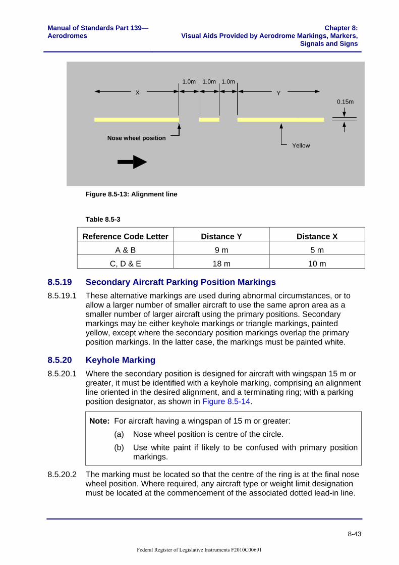
8.5.18 Alignment Line 8.5.18.1 The alignment line must extend from the location of the nose wheel in the
parked position, backwards under the body of the aircraft for a distance ‘X’ in Table 8.5-3. The line must also extend forward, commencing at a point 3 m past the most forward nose wheel position and extending for a distance ‘Y’, in the table. A 1 m long section of the alignment line must be placed in the centre of the 3 m gap, as shown in Figure 8.5-13.
Federal Register of Legislative Instruments F2010C00691
Manual of Standards Part 139—Aerodromes
Chapter 8:Visual Aids Provided by Aerodrome Markings, Markers,
Signals and Signs
8-43
Nose wheel position
X Y0.15m
1.0m1.0m1.0m
Yellow
Figure 8.5-13: Alignment line
Table 8.5-3
Reference Code Letter Distance Y Distance X A & B 9 m 5 m
C, D & E 18 m 10 m
8.5.19 Secondary Aircraft Parking Position Markings 8.5.19.1 These alternative markings are used during abnormal circumstances, or to
allow a larger number of smaller aircraft to use the same apron area as a smaller number of larger aircraft using the primary positions. Secondary markings may be either keyhole markings or triangle markings, painted yellow, except where the secondary position markings overlap the primary position markings. In the latter case, the markings must be painted white.
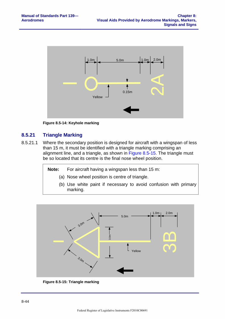
8.5.20 Keyhole Marking 8.5.20.1 Where the secondary position is designed for aircraft with wingspan 15 m or
greater, it must be identified with a keyhole marking, comprising an alignment line oriented in the desired alignment, and a terminating ring; with a parking position designator, as shown in Figure 8.5-14.
Note: For aircraft having a wingspan of 15 m or greater: (a) Nose wheel position is centre of the circle. (b) Use white paint if likely to be confused with primary position
markings.
8.5.20.2 The marking must be located so that the centre of the ring is at the final nose wheel position. Where required, any aircraft type or weight limit designation must be located at the commencement of the associated dotted lead-in line.
Federal Register of Legislative Instruments F2010C00691
Manual of Standards Part 139—Aerodromes
Chapter 8:Visual Aids Provided by Aerodrome Markings, Markers,
Signals and Signs
8-44
2A
5.0m
0.15m
2.0m1.0m1.0m
Yellow
Figure 8.5-14: Keyhole marking
8.5.21 Triangle Marking 8.5.21.1 Where the secondary position is designed for aircraft with a wingspan of less
than 15 m, it must be identified with a triangle marking comprising an alignment line, and a triangle, as shown in Figure 8.5-15. The triangle must be so located that its centre is the final nose wheel position.
Note: For aircraft having a wingspan less than 15 m: (a) Nose wheel position is centre of triangle. (b) Use white paint if necessary to avoid confusion with primary
marking.
3B
5.0m
3.0m
3.0m
2.0m1.0m
3.0m
Yellow
Figure 8.5-15: Triangle marking
Federal Register of Legislative Instruments F2010C00691

Manual of Standards Part 139—Aerodromes
Chapter 8:Visual Aids Provided by Aerodrome Markings, Markers,
Signals and Signs
8-45
8.5.22 Lead-out Line 8.5.22.1 Must comprise a broken line, painted yellow; stripes 1 m long and 0.15 m
wide, spaced at 1 m intervals. The lead-out line must commence from the alignment line at least 3 m from the nose wheel position, as shown in Figure 8.5-16.
8.5.22.2 The lead-out line must extend to a point from where the pilot can clearly see the taxi guideline. If arrow indicators are inserted, the first arrow must be at least 15 m from the alignment line, with subsequent arrows at 30 m spacing.
1.0m 1.0m
0.4m 1.0m
0.4m
Alig
nmen
t Li
ne
Yellow
Figure 8.5-16: Lead-out line
8.5.23 Designation Markings 8.5.23.1 Designation markings are used to provide supplementary information, on all
asphalt, sealed and concrete aprons where there is more than one aircraft parking position. Primary parking positions must be numbered sequentially with no omissions. Secondary positions must be identified with the same numbers as the associated primary position, together with an alphabetical suffix.
8.5.24 Aircraft Parking Position Designation 8.5.24.1 The parking position designation must be located adjacent to the parking
position, either on the ground or on the aerobridge, and be visible to the pilot. 8.5.24.2 For fixed wing aircraft, the position designation, marked on the ground, must
be placed 4 m forward of the nose wheel position and 5 m to the left, as viewed by the pilot. The designation must be yellow, and consist of characters 1 m high in a 2 m inside diameter ring of 0.15 m line thickness, as shown in Figure 8.5-17.
8.5.24.3 At aerobridge positions, the aerobridge designation must be the same as the associated parking position designation. The size of the position designation must not be less than the legend and face size specified in Table 8.6-1.
Federal Register of Legislative Instruments F2010C00691

Manual of Standards Part 139—Aerodromes
Chapter 8:Visual Aids Provided by Aerodrome Markings, Markers,
Signals and Signs
8-46
2.0m0.15m
5.0m
4.0m
Nose wheel positionB
737
2 1.0m
Yellow
Figure 8.5-17: Aircraft parking position designation
8.5.24.4 An illustration showing a combination of all the aircraft parking position markings at an aircraft parking position is shown in Figure 8.5-18.
Alig
nmen
t li n
eA
lign m
ent
line
Lead-out line
Lead-in line
3Pilot stop line
Aircraft parking position designation
Marshaller stop line
B737B727 B737
B727
Nose wheel position
Figure 8.5-18: Aircraft parking position markings
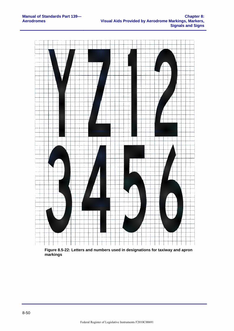
8.5.25 Designation Characters for Taxi and Apron Markings 8.5.25.1 All letters and numbers used in designations for taxi and apron markings
must conform in style and proportion to the following illustrations. Actual dimensions must be determined in proportion to the overall height standard for each specific designator. The grid spacing used in the following illustrations is 0.20 m.
Federal Register of Legislative Instruments F2010C00691

Manual of Standards Part 139—Aerodromes
Chapter 8:Visual Aids Provided by Aerodrome Markings, Markers,
Signals and Signs
8-47
Figure 8.5-19: Letters and numbers used in designations for taxiway and apron markings
Federal Register of Legislative Instruments F2010C00691

Manual of Standards Part 139—Aerodromes
Chapter 8:Visual Aids Provided by Aerodrome Markings, Markers,
Signals and Signs
8-48
Figure 8.5-20: Letters and numbers used in designations for taxiway and apron markings
Federal Register of Legislative Instruments F2010C00691

Manual of Standards Part 139—Aerodromes
Chapter 8:Visual Aids Provided by Aerodrome Markings, Markers,
Signals and Signs
8-49
Figure 8.5-21: Letters and numbers used in designations for taxiway and apron markings
Federal Register of Legislative Instruments F2010C00691
Manual of Standards Part 139—Aerodromes
Chapter 8:Visual Aids Provided by Aerodrome Markings, Markers,
Signals and Signs
8-50
Figure 8.5-22: Letters and numbers used in designations for taxiway and apron markings
Federal Register of Legislative Instruments F2010C00691

Manual of Standards Part 139—Aerodromes
Chapter 8:Visual Aids Provided by Aerodrome Markings, Markers,
Signals and Signs
8-51
Figure 8.5-23: Letters and numbers used in designations for taxiway and apron markings
Federal Register of Legislative Instruments F2010C00691

Manual of Standards Part 139—Aerodromes
Chapter 8:Visual Aids Provided by Aerodrome Markings, Markers,
Signals and Signs
8-52
8.5.26 Tug operator Guidance Marking 8.5.26.1 Tug operator guidance marking must be provided on aprons where aircraft
are being pushed back by tugs.
8.5.27 Aircraft Push-back Lines 8.5.27.1 The push-back line must be a broken line, painted white, comprising stripes
1 m long and 0.15 m wide, spaced at 1 m intervals. The line must be based on the required path of the nose wheel of the design aircraft. Where the line is used for tug operations with aircraft of reference code letter C, D and E, the 10 m before the tow bar disconnect point must be straight.
8.5.28 Tug Parking Position Lines 8.5.28.1 The tug parking position line marking must be provided at aerobridges and
other power-in/push-out aircraft parking positions, to ensure parked tugs are clear of incoming aircraft. The marking must consist of a red line 0.10 m wide in the shape of a U, 3.5 m by 1.0 m commencing 3 m from the nose of the critical aircraft, as illustrated, below.
3.5m
1.0m
0.10m
0.15m
Alignment line
3.0mClearance to critical A/C nose
Red
Yellow
Figure 8.5-24: Tug parking position line
8.5.29 Towbar Disconnect Markings 8.5.29.1 The towbar disconnect point shown in Figure 8.5-25 must be located at the
point of disconnection and must consist of a white line, 1.5 m long and 0.15 m wide, located on the left side of the taxi guideline or push-back line, as viewed from the tug; touching the guideline and at right angles to it.
Federal Register of Legislative Instruments F2010C00691

Manual of Standards Part 139—Aerodromes
Chapter 8:Visual Aids Provided by Aerodrome Markings, Markers,
Signals and Signs
8-53
Aircraft push-back lineWhite
Direction of travel
1.5m
.15m
Figure 8.5-25: Towbar disconnect marking
8.5.30 Push-back Limit Markings 8.5.30.1 Push-back limit markings must comprise two parallel white lines at right
angles to and symmetrical about the push back line. The marking must be 1 m long, 0.15 m wide and lines 0.15 m apart, as shown below.
1.0m 1.0m1.0m
0.15m 0.15m
0.15m
0.15m
1.0m
Aircraft push-back line
White
Figure 8.5-26: Push-back limit marking
8.5.31 Push-back Alignment Bars 8.5.31.1 Push-back alignment bars are provided to assist tug operators to align an
aircraft correctly at the end of the push-back manoeuvre. The marking must be a broken white line, comprising stripes 1 m long and 0.15 m wide, spaced at 1 m intervals, for a length of 30 metres, aligned in the desired direction. The marking must commence 3 m past the tow disconnect marking, as shown below.
Federal Register of Legislative Instruments F2010C00691

Manual of Standards Part 139—Aerodromes
Chapter 8:Visual Aids Provided by Aerodrome Markings, Markers,
Signals and Signs
8-54
1.0m
3.0m
1.0m
30.0m
0.15m
Push-back limit marking
Direction of travel
White
1.0m
3.0m
1.0m
30.0m
0.15m
Push-back limit marking
Direction of travel
White
Figure 8.5-27: Push-back alignment line
8.5.32 Passenger Path Markings 8.5.32.1 Where provided, passenger path markings are provided to assist the orderly
movement of passengers embarking or disembarking. Passenger path markings must be provided in accordance with the pattern and colour of the relevant State Road Authority pedestrian crossing marking standards. The width of the passenger pathway is to be commensurate with the expected pedestrian traffic.
8.5.32.2 The following diagram illustrates a typical layout for a pedestrian crossing.
Federal Register of Legislative Instruments F2010C00691

Manual of Standards Part 139—Aerodromes
Chapter 8:Visual Aids Provided by Aerodrome Markings, Markers,
Signals and Signs
8-55
0.5m
0.5m
2.0m
White
Figure 8.5-28: Pedestrian crossing
Federal Register of Legislative Instruments F2010C00691

Manual of Standards Part 139—Aerodromes
Chapter 8:Visual Aids Provided by Aerodrome Markings, Markers,
Signals and Signs
8-56
8.5.33 Typical Apron Markings 8.5.33.1 The following Figure 8.5-29 illustrates an apron with typical apron markings.
Parking weight limit line
MAX 5700 KG
PA
RK
ING
CLE
AR
AN
CE
PARKING CLEARANCE PARKING CLEARANCE
PA
RK
ING
CLE
AR
AN
CE
4
3
B737
Pilot turn line
Alignment line
Keyhole marking Lead-out line
Pilot stop line
B737
B727 EQ
UIPM
ENT
CLEA
RANCE
4 Parking position designation
EQ
UIP
ME
NT
ST
OR
AG
E
Equipment clearance line
Lead-in line
Lead-in line designation
Tug parking position line
B7373
Marshaller stop line
Aeroplane push-back line
Towbar disconnect marking
Push-back alignment line
Taxi guideline
Pavement edge
Apr
on ro
ad
Direction of travel
Direction of travel
Direction of travel
Figure 8.5-29: Typical apron markings
Federal Register of Legislative Instruments F2010C00691

Manual of Standards Part 139—Aerodromes
Chapter 8:Visual Aids Provided by Aerodrome Markings, Markers,
Signals and Signs
8-57
Section 8.6: Movement Area Guidance Signs (MAGS)
8.6.1 Introduction 8.6.1.1 Signs that convey messages that must be obeyed by pilots are known as
mandatory instruction signs. These signs must have white lettering on a red background.
8.6.1.2 Signs that convey messages of information are known as information signs. These signs must have either black lettering on a yellow background, or yellow lettering on a black background.
8.6.1.3 Mandatory signs must be provided at major international aerodromes, and at other aerodromes that have air traffic control and for which CASA determines these are required for safety reasons.
8.6.1.4 Aerodrome operators will consult with airlines and with Air Traffic Control, on the need for MAGS with information. Notwithstanding this, MAGS with information must be provided at aerodromes where taxiway intersection departures are promulgated in the AIP.
8.6.2 Naming of taxiways 8.6.2.1 The following convention must be used in the naming of taxiway location
signs: (a) a single letter must be used, without numbers, to designate each main
taxiway; (b) the same letter must be used throughout the length of taxiway, except
where a turn of 90 degrees or more is made to join a runway, a different letter may be assigned to that portion of taxiway after the turn;
(c) for each intersecting taxiway, a different single letter must be used; (d) to avoid confusion, letters I, O and X must not be used, letter Q should
only be used where unavoidable; (e) at aerodromes where the number of taxiways are or will be large,
alphanumeric designators may be used for short intersecting taxiways. Successive intersecting taxiways must use the same letter, with sequential numbers. If sequential numbers are not practicable, due to geometry of the taxiway system; all pilot-used taxiway plans (aerodrome charts) must include advice as to the missing designators;
(f) the use of letters and numbers must be easily comprehensible. Should it ever be necessary to use double-digit alphanumeric designators, care must be taken to ensure the numbers used in the taxiway designation cannot in any way be confused with the runway designations.
Federal Register of Legislative Instruments F2010C00691

Manual of Standards Part 139—Aerodromes
Chapter 8:Visual Aids Provided by Aerodrome Markings, Markers,
Signals and Signs
8-58
8.6.3 Dimensions, Location and Lettering 8.6.3.1 Signs must be located to provide adequate clearance to passing aircraft. The
depth and width of the signboard is dependent on the location of the sign, the size of the characters and the length of message conveyed.
8.6.3.2 Where MAGS are provided only on one side of the taxiway, they must be located on the pilots’ left side unless this is impracticable. Where MAGS are to be read from both directions, they must be oriented so as to be at right angles to the taxi guideline. Where MAGS are to be read in one direction only, they must be oriented so as to be at 75 degrees to the taxi guideline.
8.6.4 Sign Size and Location Distances, Including Runway Exit Signs 8.6.4.1 Sign size and location distances must be in accordance with Table 8.6-1.
Table 8.6-1
Sign Height (mm) Code
Number Type Legend Face
(min) Installed
(max)
Perpendicular distance from
defined taxiway pavement edge to near side of sign
Perpendicular distance from
defined runway pavement edge to near side of sign
1 or 2a I 200 400 700 5-11 m 3-10 m 1 or 2 M 300 600 900 5-11 m 3-10 m 3 or 4a I 300 600 900 11-21 m 8-15 m 3 or 4 M 400 800 1100 11-21 m 8-15 m
a For runway exit signs, use the mandatory size. I Information signs. M Mandatory instruction signs.
8.6.4.2 The stroke width of letters and arrows must be:
Legend height Stroke width 200 mm 32 mm
300 mm 48 mm
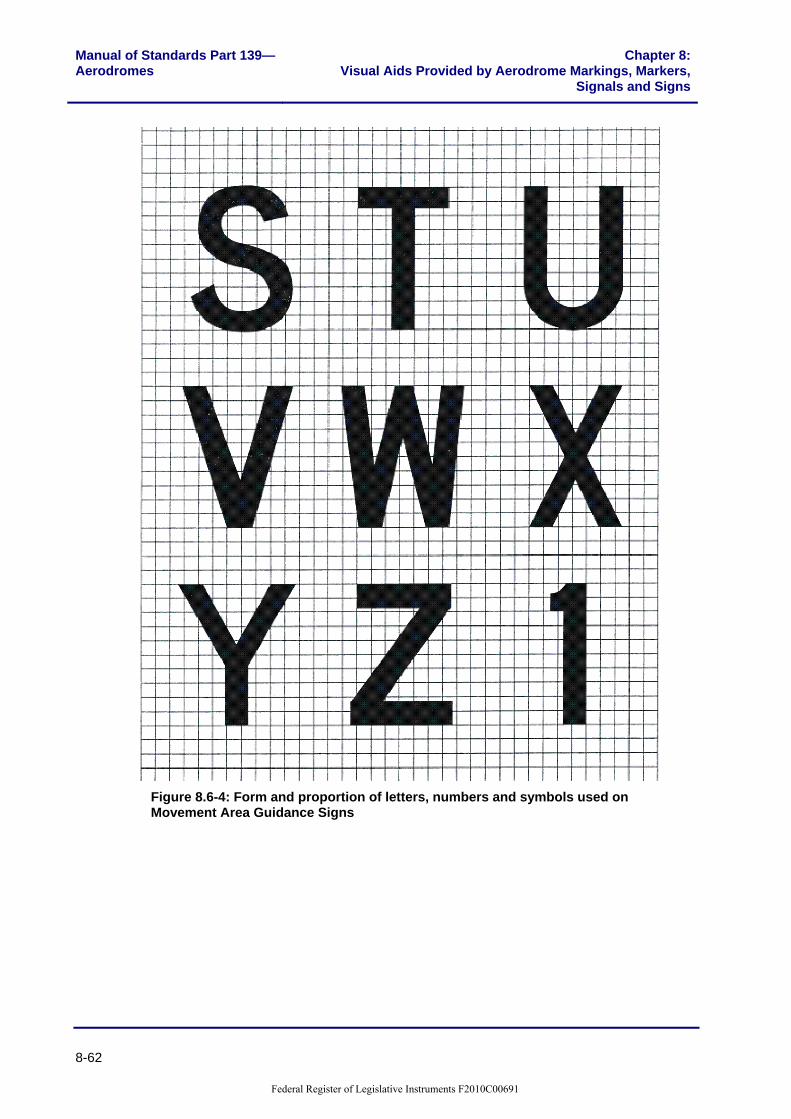
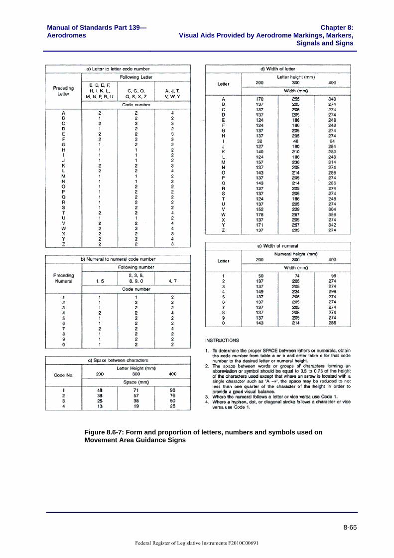
400 mm 64 mm 8.6.4.3 The form and proportion of the letters, numbers and symbols used on
movement area guidance signs must be in accordance with Figure 8.6-1 to Figure 8.6-7. The grid spacing used in the following illustrations is 0.20 m.
Federal Register of Legislative Instruments F2010C00691

Manual of Standards Part 139—Aerodromes
Chapter 8:Visual Aids Provided by Aerodrome Markings, Markers,
Signals and Signs
8-59
Figure 8.6-1: Form and proportion of letters, numbers and symbols used on Movement Area Guidance Signs
Federal Register of Legislative Instruments F2010C00691

Manual of Standards Part 139—Aerodromes
Chapter 8:Visual Aids Provided by Aerodrome Markings, Markers,
Signals and Signs
8-60
Figure 8.6-2: Form and proportion of letters, numbers and symbols used on Movement Area Guidance Signs
Federal Register of Legislative Instruments F2010C00691

Manual of Standards Part 139—Aerodromes
Chapter 8:Visual Aids Provided by Aerodrome Markings, Markers,
Signals and Signs
8-61
Figure 8.6-3: Form and proportion of letters, numbers and symbols used on Movement Area Guidance Signs
Federal Register of Legislative Instruments F2010C00691
Manual of Standards Part 139—Aerodromes
Chapter 8:Visual Aids Provided by Aerodrome Markings, Markers,
Signals and Signs
8-62
Figure 8.6-4: Form and proportion of letters, numbers and symbols used on Movement Area Guidance Signs
Federal Register of Legislative Instruments F2010C00691

Manual of Standards Part 139—Aerodromes
Chapter 8:Visual Aids Provided by Aerodrome Markings, Markers,
Signals and Signs
8-63
Figure 8.6-5: Form and proportion of letters, numbers and symbols used on Movement Area Guidance Signs
Federal Register of Legislative Instruments F2010C00691

Manual of Standards Part 139—Aerodromes
Chapter 8:Visual Aids Provided by Aerodrome Markings, Markers,
Signals and Signs
8-64
Figure 8.6-6: Form and proportion of letters, numbers and symbols used on Movement Area Guidance Signs
Federal Register of Legislative Instruments F2010C00691
Manual of Standards Part 139—Aerodromes
Chapter 8:Visual Aids Provided by Aerodrome Markings, Markers,
Signals and Signs
8-65
Figure 8.6-7: Form and proportion of letters, numbers and symbols used on Movement Area Guidance Signs
Federal Register of Legislative Instruments F2010C00691

Manual of Standards Part 139—Aerodromes
Chapter 8:Visual Aids Provided by Aerodrome Markings, Markers,
Signals and Signs
8-66
8.6.4.4 The face width of a sign must provide on either side of the legend a minimum width equal to half the height of the legend. In the case of a single letter sign, this width must be increased to the height of the legend. In all cases, the face width of a mandatory instruction sign provided on one side of a taxiway only, must not be less than: (a) 1.94 m where the code number is 3 or 4; and (b) 1.46 m where the code number is 1or 2.
8.6.5 Structural 8.6.5.1 MAGS must be lightweight and frangibly mounted. They must be constructed
so as to withstand a wind velocity of up to 60 m/sec without sustaining damage. Mountings must be constructed so as to fail, for frangibility requirements, under a static load not exceeding 8 kPa distributed over the sign face.
8.6.6 Illumination 8.6.6.1 All MAGS, except those where internal illumination is provided, must be
made of retro-reflective class one material. Illumination must be provided to all mandatory instruction signs and information signs meant for use by code 4 aircraft. Illumination is optional for information signs intended to serve Code 1, 2 or 3 aircraft; however, if the location of a sign is such that the retro-reflectiveness is ineffective, illumination must be provided. Both external or internal illumination is acceptable, but care must be taken, to prevent dazzle.
8.6.6.2 The average sign luminance must be as follows: (a) where operations are conducted in runway visual range of less than
800 m, the average sign luminance must be at least: Red 30 cd/m2 Yellow 150 cd/m2 White 300 cd/m2
(b) where operations are conducted at night, in runway visual range of 800 m or greater, average sign luminance must be at least:
Red 10 cd/m2 Yellow 50 cd/m2 White 100 cd/m2
8.6.6.3 The luminous ratio between red and white elements of a mandatory sign must not be less than 1:5 and not greater than 1:10.
8.6.6.4 The average luminance of the sign must be calculated in accordance with ICAO Annex 14, Volume 1, Appendix 4, Figure 4.1.
Federal Register of Legislative Instruments F2010C00691

Manual of Standards Part 139—Aerodromes
Chapter 8:Visual Aids Provided by Aerodrome Markings, Markers,
Signals and Signs
8-67
8.6.6.5 In order to achieve uniformity of signal, luminance values must not exceed a ratio of 1.5:1 between adjacent grid points. Where the grid spacing is 7.5 cm, the ratio between luminance values of adjacent grid points must not exceed a ratio of 1.25:1. The ratio between the maximum and minimum luminance value over the whole sign face must not exceed 5:1.
8.6.6.6 At an aerodrome where land and hold short operations (LAHSO) are conducted, the signs specifically provided for LAHSO such as runway/runway intersection signs and distance-to-go signs must be electrically connected such that they will be illuminated when the lighting of the runway on which LAHSO are conducted is switched on.
8.6.6.7 Runway exit signs that are required for LAHSO must be illuminated where LAHSO are conducted at night.
8.6.6.8 Signs must have colours red, white, yellow and black, that comply with the relevant recommendations in ICAO Annex 14, Volume 1, Appendix 1, for externally illuminated signs, retro-reflective signs and transilluminated signs, as appropriate.
8.6.7 MAGS with Mandatory Instructions 8.6.7.1 MAGS with mandatory instructions include runway designation signs,
category I, II or III holding position signs, runway-holding position signs, Aircraft NO ENTRY signs, vehicular STOP signs and runway/runway intersection signs.
8.6.8 Runway Designation Signs 8.6.8.1 A runway designation sign, as illustrated in Figure 8.6-8, must be provided at
a runway/taxiway intersection, where a pattern ‘A’ runway holding position marking is provided. Only the designation for one end of the runway must be shown where the taxiway intersection is located at or near that end of the runway. Designations for both ends of the runway, properly orientated with respect to the viewing position of the sign, must be shown where the taxiway is located elsewhere.
8.6.8.2 A taxiway location sign must be provided alongside the runway designation sign, in the outboard (farthest from the taxiway) position.
8.6.8.3 A runway designation sign must be provided at least on the left side of a taxiway facing the direction of approach to the runway. Where practicable, a runway designation sign is to be provided on each side of the taxiway.
Figure 8.6-8: Runway designation signs with taxiway location sign
Federal Register of Legislative Instruments F2010C00691

Manual of Standards Part 139—Aerodromes
Chapter 8:Visual Aids Provided by Aerodrome Markings, Markers,
Signals and Signs
8-68
8.6.9 Category I, II or III Runway Designation Signs 8.6.9.1 Where a pattern ‘B’ taxi-holding position marking is provided, the sign, as
shown below, must be provided on each side of the taxiway.
Figure 8.6-9: Category I runway-holding position sign
8.6.10 Runway Holding Position Sign 8.6.10.1 Runway-holding position signs must be provided at a taxiway location other
than an intersection where the air traffic control has a requirement for aircraft to stop, such as entry to an ILS sensitive area. The sign is a taxiway designation sign, but with white lettering on a red background.
Figure 8.6-10: Mandatory runway-holding position sign
8.6.11 Aircraft NO ENTRY Sign 8.6.11.1 A NO ENTRY sign, consisting of a white circle with a horizontal bar in the
middle, on a red background, must be provided at the entrance of an area to which entry is prohibited. Where practicable, a NO ENTRY sign must be located on each side of the taxiway.
Red
White
Figure 8.6-11: Aircraft NO ENTRY sign
8.6.12 Vehicular STOP Signs 8.6.12.1 Where required, vehicular ‘STOP’ signs can be provided at road/taxiway
intersections, road holding positions, or entrance to ILS sensitive areas. This sign should be the same as a local road traffic sign. In addition, the vehicular holding position should be marked in accordance with local traffic pavement marking. See also Section 6.4 for provision and location of a road-holding position.
8.6.13 Runway/Runway Intersection Signs 8.6.13.1 These are runway designation signs, which must be provided on each side of
the runway used in LAHSO, to identify the intersecting runway ahead. The
Federal Register of Legislative Instruments F2010C00691

Manual of Standards Part 139—Aerodromes
Chapter 8:Visual Aids Provided by Aerodrome Markings, Markers,
Signals and Signs
8-69
sign must show the designation of the intersecting runway, oriented with respect to the viewing position of the sign, and separated by a dash. For example, ‘15-33’ indicates the runway threshold ‘15’ is to the left, and ‘33’ is to the right. Signs are to be located at the Hold Short Line which must be at least 75 m from the centreline of the intersecting runway.
8.6.13.2 The overall height of the sign above the ground, and offset from the edge of the runway pavement, must be such as to provide at least 300 mm clearance between the top of the sign and any part of the most critical aircraft using the runway when the outer edge of the wheel of the aircraft is at the runway pavement edge.
8.6.14 MAGS with Information 8.6.14.1 MAGS with information include taxiway location signs, direction signs,
destination signs, take-off run available signs, runway exit signs, distance to go signs, and, where required, LAHSO distance to go signs.
8.6.15 Taxiway Location Signs 8.6.15.1 A location sign is normally provided in conjunction with a direction sign or a
runway designation sign.
ABlackYellow
Figure 8.6-12: Taxiway location sign
Federal Register of Legislative Instruments F2010C00691

Manual of Standards Part 139—Aerodromes
Chapter 8:Visual Aids Provided by Aerodrome Markings, Markers,
Signals and Signs
8-70
8.6.16 Direction Signs 8.6.16.1 Each taxiway direction must be indicated by an arrow, as shown below. The
sign must have black letters with yellow background. A direction sign must be complemented by a location sign, except where the taxiway designation is adequately displayed by previous location signs along the taxiway.
C B C
Yellow
Black Figure 8.6-13: Direction/location/direction sign
8.6.16.2 At a taxiway/taxiway intersection, information signs must be located prior to the intersection and in line with the taxiway intersection marking.
8.6.17 Destination Signs 8.6.17.1 Destination signs must have black letters on yellow background, as shown
below. They advise pilots of facilities on, or near, the movement area. This sign must not be co-located with a location or direction sign.
APRON YellowBlack
Figure 8.6-14: Destination sign
8.6.17.2 Examples of common sign text used for destination signs are set out below:
Sign text Meaning RAMP or APRON General parking, servicing and loading area. PARK or PARKING Aircraft parking area CIVIL Civilian areas of joint-use aerodromes MIL Military area of a joint-use aerodrome. CARGO Freight or cargo handling area. INTL International areas DOM Domestic areas RUNUP Run-up areas AC Altimeter check point VOR VOR check point FUEL Fuel or service area HGR Hangar or hangar area
Federal Register of Legislative Instruments F2010C00691

Manual of Standards Part 139—Aerodromes
Chapter 8:Visual Aids Provided by Aerodrome Markings, Markers,
Signals and Signs
8-71
8.6.18 Take-off Run Available Sign 8.6.18.1 The take-off run available sign indicates to pilots the length of take-off run
available from a particular taxiway, where intersection departures are available. This sign is provided to allow pilots to have final reassurance that they are at the correct take-off location: (a) where the take-off point is close to the start of a runway, the sign is to
show the designation of the take-off runway, and the take-off run available in metres, as shown in Figure 8.6-15.
(b) where the take-off point is not close to the start of the runway, the sign is to show the take-off run available in metres, plus an arrow, appropriately located and orientated, indicating the direction in which that take-off run is available, as shown in Figure 8.6-16.
(c) where intersection departures are available in both directions from the position, two signs, one for each direction of take-off, are required.
(d) the take-off run available signs are to be located abeam the runway- holding position on the entry taxiway. Where one take-off run available sign is provided, it is to be located on the left hand side of the taxiway. Where take-off is available in both directions, the two signs are to be located one on each side of the taxiway, corresponding to the direction of take-off. Take-off run available signs must not obscure a pilot’s view of any mandatory instruction signs.
16 - 3450 2500Yellow
Black
Yellow
Black
Figure 8.6-15: Take off run available sign Figure 8.6-16 Take-off run available sign
8.6.19 Runway Exit Signs 8.6.19.1 Runway exit signs, as shown below, advise pilots of the designation and
direction of a taxiway from which they can exit. Must be provided for a runway used in LAHSO, except when used only by Performance Category A aircraft, as defined in the AIP. For this purpose, Non-jet aircraft below 5,700 kg may be regarded as Category A aircraft.
8.6.19.2 The sign must consist of black lettering on a yellow background, with a black arrow outboard of the taxiway designator, or to the right of the designator for exits to the right, and to the left for exits to the left.
Federal Register of Legislative Instruments F2010C00691

Manual of Standards Part 139—Aerodromes
Chapter 8:Visual Aids Provided by Aerodrome Markings, Markers,
Signals and Signs
8-72
8.6.19.3 The runway exit sign must be located on the same side of the exit taxiway, 60 m prior to the exit junction where the runway code number is 3 or 4 and 30 m where the runway code number is 1 or 2.
A3 YellowBlack
Figure 8.6-17: Runway exit sign
8.6.20 LAHSO Distance To Go Signs 8.6.20.1 LAHSO distance to go signs may be required at a runway where a pilot
engaged in LAHSO cannot readily see the hold short line due to runway geometry. Where needed, the distance to go signs must be provided on the left-hand side of the runway as seen by the landing pilot, in increments of 300 m from the hold short line. Three signs with inscriptions of 300, 600 and 900 must be provided. Below the numerals, the designation of the intersecting runway must be displayed in smaller characters, as shown below.
8.6.20.2 The sign must consist of black letters and numbers, on a yellow background. The height of the distance inscription must be 600 mm and the runway designation 200 mm.
34L - 16R600 Yellow
Black
Figure 8.6-18: Distance-to-go sign
Federal Register of Legislative Instruments F2010C00691

Manual of Standards Part 139—Aerodromes
Chapter 8:Visual Aids Provided by Aerodrome Markings, Markers,
Signals and Signs
8-73
Section 8.7: Wind Direction Indicators
8.7.1 Requirements 8.7.1.1 CASR Part 139 requires the aerodrome operator to install and maintain at
least one wind direction indicator at the aerodrome. CASA may issue directions requiring additional wind direction indicators to be provided.
8.7.1.2 CASR Part 139 also requires that non-precision approach runways be provided with a wind direction indicator at the threshold of the runway. However, subject to paragraph 8.7.1.3, for runways 1200m or less in length one centrally located wind direction indicator visible from both approaches and the aircraft parking area is acceptable.
8.7.1.3 Paragraph 8.7.1.2 does not apply to a runway if surface wind information is passed to the pilots of aircraft approaching the runway through: (a) an automatic weather observing system that:
(i) is compatible with the Bureau of Meteorology weather observing system, and
(ii) provides surface wind information through an aerodrome weather information broadcast, or
(b) an approved observer having a communication link with pilots through which timely information about surface wind may be clearly passed to them; or
(c) any other approved means of providing surface wind information. 8.7.1.4 A wind direction indicator must be located so as to be visible from aircraft that
are in flight or aircraft that are on the movement area. 8.7.1.5 A wind direction indicator must be located so as to be free from the effects of
air disturbance caused by buildings or other structures. 8.7.1.6 A wind direction indicator provided at the threshold of a runway must be
located: (a) except if it is not practicable to do so, on the left hand side of the
runway as seen from a landing aircraft; and (b) outside the runway strip; and (c) clear of the transitional obstacle limitation surface.
8.7.1.7 If practicable to do so, a wind direction indicator provided at the threshold of a runway must be located 100 metres upwind of the threshold.
Federal Register of Legislative Instruments F2010C00691

Manual of Standards Part 139—Aerodromes
Chapter 8:Visual Aids Provided by Aerodrome Markings, Markers,
Signals and Signs
8-74
8.7.2 Standards 8.7.2.1 A wind direction indicator must consist of a tapering fabric sleeve attached to
a pole at its wide end 6.5 m above the ground. 8.7.2.2 The sleeve must be 3.65 m long and taper from 900 millimetres in diameter
to 250 millimetres in diameter. 8.7.2.3 The wide end must be mounted on a rigid frame to keep the end of the
sleeve open and attached to the pole so as to allow it to move around freely. 8.7.2.4 The fabric of the primary wind direction indicator must be white and that of
any additional wind direction indicator must be: (a) yellow; if it is not intended to be illuminated at night; or (b) if it is intended to be illuminated at night; either white, or another colour
that is clearly visible when illuminated.
Note: Natural or synthetic fibres having weight range of at least 270 to 275 g/m2 have been used effectively as wind indicator sleeve material.
8.7.2.5 The primary wind direction indicator must be located in the centre of a circle 15 m in diameter, coloured black and bordered: (a) by a white perimeter 1.2 m wide; or (b) by a ring of 15 equally spaced white markers each with a base not less
than 0.75 m in diameter.
Figure 8.7-1: Wind Direction Indicator
8.7.2.6 For the illumination of wind direction indicators see Chapter 9.
Federal Register of Legislative Instruments F2010C00691

Manual of Standards Part 139—Aerodromes
Chapter 8:Visual Aids Provided by Aerodrome Markings, Markers,
Signals and Signs
8-75
Section 8.8: Ground Signals
8.8.1 Signal Areas 8.8.1.1 A signal area must be:
(a) 9 metres in diameter; (b) black, (c) bordered by:
(i) a white border 1 metre wide; or (ii) 6 equally spaced white markers, each with a base not less than
0.75 m in diameter; and (d) not more than 15 m from the wind direction indicator, or, if applicable,
the primary wind direction indicator. The primary wind direction indicator is located closest to the apron of the aerodrome.
9m9m 1m
WhiteWhite
Black
Black
Figure 8.8-1: Signal Area
8.8.2 Ground Signals in Signal Area 8.8.2.1 A ‘total unserviceability’ signal must be displayed in a signal area when an
aerodrome is closed to landing aircraft. 8.8.2.2 A ‘total unserviceability’ signal must consist of 2 white strips not less than
0.9 m wide and 6 m long, bisecting each other at right angles.
Federal Register of Legislative Instruments F2010C00691

Manual of Standards Part 139—Aerodromes
Chapter 8:Visual Aids Provided by Aerodrome Markings, Markers,
Signals and Signs
8-76
8.8.2.3 A ‘restricted operations’ signal must be displayed in the signal area at an aerodrome with more than one type of surface on its movement area, if aircraft are only to use: (a) the sealed runways, taxiways and aprons; or (b) the gravel runways; where there are no sealed runways, taxiways and
aprons. 8.8.2.4 For the purposes of Paragraph 8.8.2.3:
(a) a sealed runway, taxiway or apron is one whose surface is wholly or mainly sealed; and
(b) a gravel runway, taxiway or apron is one whose surface is wholly or mainly gravel.
(c) the ‘restricted operations’ signal must consist of 2 white circles 1.5 m in diameter, connected by a white cross bar 1.5 m long and 0.4 m wide.
(d) a ‘glider operations’ signal, must consist of a white strip 5 m long and 0.4 m wide crossed at right angles by 2 strips 0.4 m wide and 2.5 m long, each being 1.05 m from the closest end of the horizontal strip, as shown below.
2.55m
0.9m2.55m
2.55m 2.55m
0.9m
White
Figure 8.8-2: Total unserviceability signal
Federal Register of Legislative Instruments F2010C00691

Manual of Standards Part 139—Aerodromes
Chapter 8:Visual Aids Provided by Aerodrome Markings, Markers,
Signals and Signs
8-77
0.4m
1.5m
1.5m
White
Figure 8.8-3: Restricted operations signal
2.5m0.4m
0.4m
5.0m
2.1m
White
Figure 8.8-4: Glider operations signal
Federal Register of Legislative Instruments F2010C00691

Manual of Standards Part 139—Aerodromes
Chapter 8:Visual Aids Provided by Aerodrome Markings, Markers,
Signals and Signs
8-78
Section 8.9: Marking of Unserviceable and Work Areas
8.9.1 Introduction 8.9.1.1 This section identifies the markings used on unserviceable areas of runways,
taxiways, aprons and holding bays and markers used to mark the boundary of unserviceable areas and limit of work areas.
8.9.2 Marking of Unserviceable Areas on Runways, Taxiways and Aprons
8.9.2.1 An unserviceability marking or closed marking must be used to indicate any part of a runway, which is not to be used by aircraft. The marking must comprise a white cross placed on the unserviceable portion of the runway.
8.9.2.2 An unserviceability marking may also be used to indicate any part of a taxiway or apron, which is not to be used by aircraft. The preferred way of marking an unserviceable part of taxiway or apron, is by the placement of unserviceable markers at the entrance to that area or around the unserviceable area.
8.9.2.3 There are two types of unserviceability markings, shown in Figure 8.9-1 and Figure 8.9-2. Where feasible, the larger marking is the preferred marking for a runway.
8.9.2.4 Unserviceability marking is not required for time-limited works.
Federal Register of Legislative Instruments F2010C00691

Manual of Standards Part 139—Aerodromes
Chapter 8:Visual Aids Provided by Aerodrome Markings, Markers,
Signals and Signs
8-79
36m
14.5m
1.8m
Runway centreline
Figure 8.9-1: Unserviceability (closed runway) marking
Runway centreline
0.9m
6m
2.55m
White
Figure 8.9-2: Unserviceability marking
8.9.2.5 The larger marking must be used on Code 4 runways when the whole or part of the runway is permanently closed or closed to aircraft operations, for more than 30 days. Markings must be displayed at each end of the unserviceable runway, and also in the intermediate area, at intervals of not more than 300 m.
Federal Register of Legislative Instruments F2010C00691

Manual of Standards Part 139—Aerodromes
Chapter 8:Visual Aids Provided by Aerodrome Markings, Markers,
Signals and Signs
8-80
8.9.2.6 The larger making should be used at an aerodrome with multiple and parallel Code 3 runways, when one or more runways, or part of a runway is closed for more than 30 days. Where provided, the markings must be displayed in accordance with Paragraph 8.9.2.5.
8.9.2.7 In other cases of runway unserviceability, if markings in accordance with the larger configuration are not used, then the smaller marking must be used. The smaller markings must be displayed at each end of the unserviceability and in the intermediate area at intervals of not more than 200 m.
8.9.3 Use of Unserviceability Markers 8.9.3.1 Unserviceability markers are shown in Figure 8.2-1. They must consist of a
white standard cone with a horizontal red stripe, 25 cm wide around its centre, half way up the cone, so as to provide three bands of colour, white-red-white.
8.9.3.2 Unserviceability markers must be displayed wherever any portion of a taxiway, apron or holding bay is unfit for the movement of aircraft but is still possible for aircraft to bypass the area safely.
8.9.4 Works Limit Markers 8.9.4.1 Works limit markers, shown in Figure 8.2-1, where used, must be spaced at
intervals marginally less than the smallest track of the plant or vehicles operating within the work area.
8.9.4.2 Other forms of work limit markers may be used for works on apron and other areas provided they are not a hazard to aircraft and other airside vehicles operating in the vicinity of the works area.
Federal Register of Legislative Instruments F2010C00691

Manual of Standards Part 139—Aerodromes
Chapter 8:Visual Aids Provided by Aerodrome Markings, Markers,
Signals and Signs
8-81
Section 8.10: Obstacle Markings
8.10.1 General 8.10.1.1 Fixed objects, temporary and permanent, which extend above the obstacle
limitation surfaces but are permitted to remain; or objects which are present on the movement area, are regarded as obstacles, and must be marked. The aerodrome operator must submit details of such obstacles to CASA, for hazard assessment and particular requirements for marking and lighting. This information must be included in the Aerodrome Manual.
8.10.1.2 CASA may permit obstacles to remain unmarked; (a) when obstacles are sufficiently conspicuous by their shape, size or
colour; (b) when obstacles are shielded by other obstacles already marked; or (c) when obstacles are lighted by high intensity obstacle lights by day.
8.10.2 Marking of Obstacles 8.10.2.1 A structure must be marked when more than 150 m higher than the
surrounding terrain. Surrounding terrain means the area within 400 m of the structure. Structures above 90 m may need to be marked, and inconspicuous structures 75 m above ground level should also be marked. Fixed objects on the aerodrome movement area, such as ILS buildings, must be marked as obstacles.
8.10.2.2 Obstacles other than wires and cables, must be painted in a pattern of contrasting colours which also contrast with the background, as agreed and set out in the Aerodrome Manual. Orange and white or red and white are normally used.
8.10.2.3 Obstacles with unbroken surfaces more than 4.5 m by 4.5 m size, must be painted in a chequered pattern of lighter and darker squares or rectangles, with sides no less than 1.5 m and no more than 3 m long, as shown in Figure 8.10-1. The corners of the obstacle must be painted in the darker colour.
Federal Register of Legislative Instruments F2010C00691
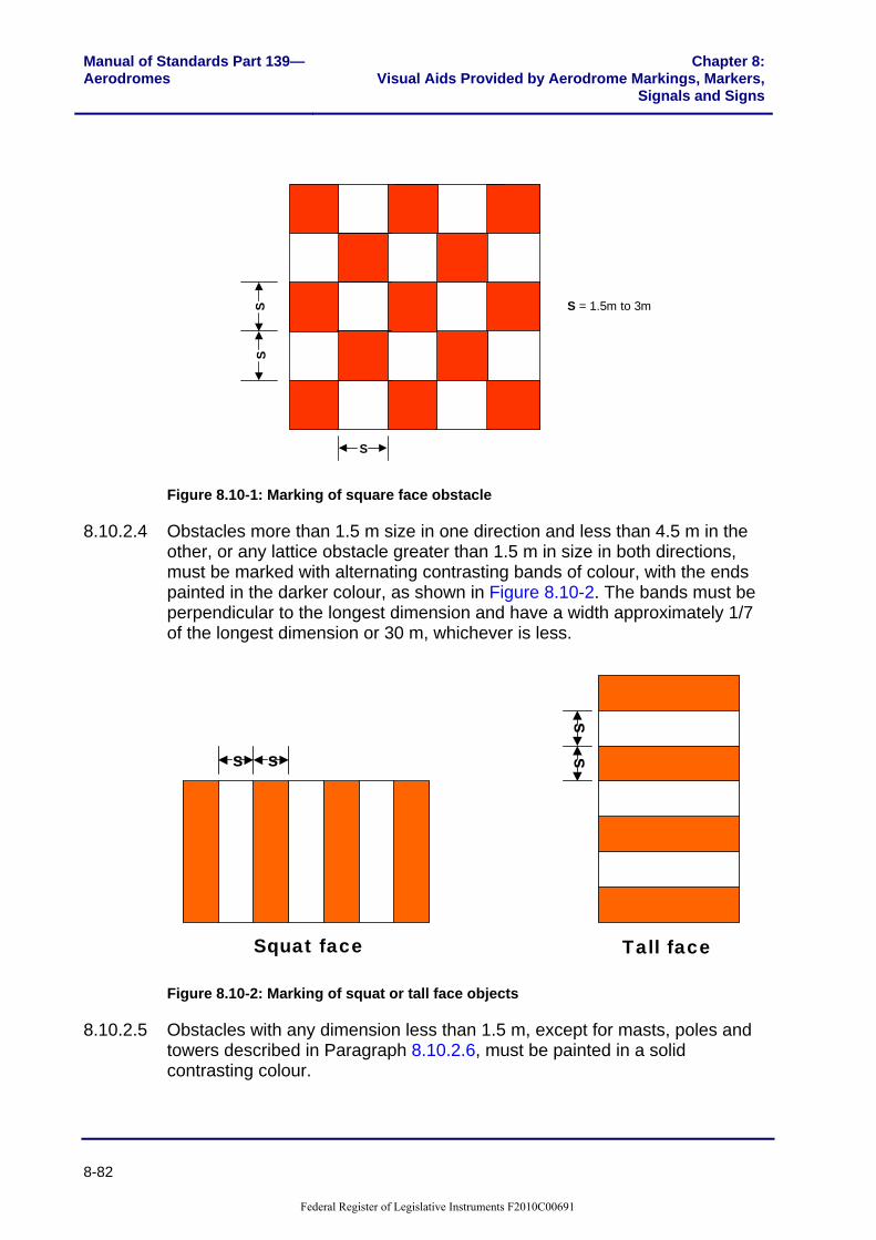
Manual of Standards Part 139—Aerodromes
Chapter 8:Visual Aids Provided by Aerodrome Markings, Markers,
Signals and Signs
8-82
SS
S = 1.5m to 3m
S
Figure 8.10-1: Marking of square face obstacle
8.10.2.4 Obstacles more than 1.5 m size in one direction and less than 4.5 m in the other, or any lattice obstacle greater than 1.5 m in size in both directions, must be marked with alternating contrasting bands of colour, with the ends painted in the darker colour, as shown in Figure 8.10-2. The bands must be perpendicular to the longest dimension and have a width approximately 1/7 of the longest dimension or 30 m, whichever is less.
s s ss
Squat face Tall face
Figure 8.10-2: Marking of squat or tall face objects
8.10.2.5 Obstacles with any dimension less than 1.5 m, except for masts, poles and towers described in Paragraph 8.10.2.6, must be painted in a solid contrasting colour.
Federal Register of Legislative Instruments F2010C00691
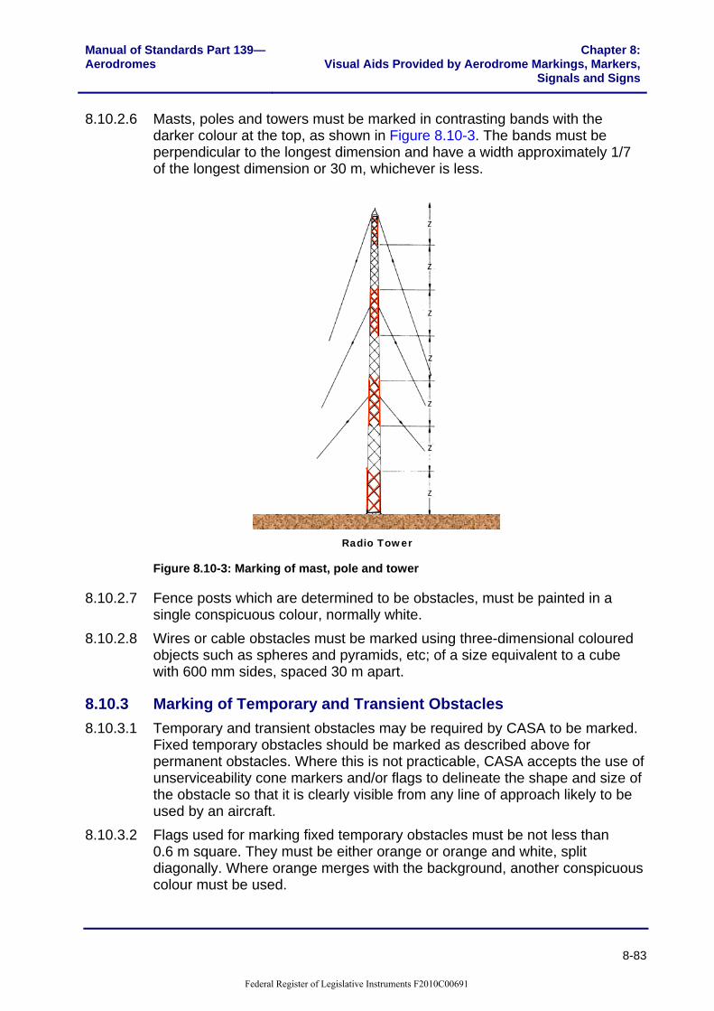
Manual of Standards Part 139—Aerodromes
Chapter 8:Visual Aids Provided by Aerodrome Markings, Markers,
Signals and Signs
8-83
8.10.2.6 Masts, poles and towers must be marked in contrasting bands with the darker colour at the top, as shown in Figure 8.10-3. The bands must be perpendicular to the longest dimension and have a width approximately 1/7 of the longest dimension or 30 m, whichever is less.
Radio Tower Figure 8.10-3: Marking of mast, pole and tower
8.10.2.7 Fence posts which are determined to be obstacles, must be painted in a single conspicuous colour, normally white.
8.10.2.8 Wires or cable obstacles must be marked using three-dimensional coloured objects such as spheres and pyramids, etc; of a size equivalent to a cube with 600 mm sides, spaced 30 m apart.
8.10.3 Marking of Temporary and Transient Obstacles 8.10.3.1 Temporary and transient obstacles may be required by CASA to be marked.
Fixed temporary obstacles should be marked as described above for permanent obstacles. Where this is not practicable, CASA accepts the use of unserviceability cone markers and/or flags to delineate the shape and size of the obstacle so that it is clearly visible from any line of approach likely to be used by an aircraft.
8.10.3.2 Flags used for marking fixed temporary obstacles must be not less than 0.6 m square. They must be either orange or orange and white, split diagonally. Where orange merges with the background, another conspicuous colour must be used.
Federal Register of Legislative Instruments F2010C00691

Manual of Standards Part 139—Aerodromes
Chapter 8:Visual Aids Provided by Aerodrome Markings, Markers,
Signals and Signs
8-84
8.10.4 Marking of Vehicles 8.10.4.1 A vehicle used regularly on the manoeuvring area by day should be painted a
single conspicuous colour, preferably yellow or orange. Where so painted, it does not require additional marking.
8.10.4.2 Vehicles not painted yellow or orange must be marked, by using either: (a) flags; or (b) vehicle warning lights, in accordance with paragraph 9.19.1.
8.10.4.3 Flags must be not less than 0.9 m square and consist of an orange and white chequered pattern, each square of which must have sides not less than 0.3 m. Where orange merges with the background, another colour that contrasts with the background must be used.
8.10.4.4 For marking of rescue and fire fighting service vehicles, see MOS 139, Subpart H, Chapter 4.
Federal Register of Legislative Instruments F2010C00691

Manual of Standards Part 139—Aerodromes
Chapter 8:Visual Aids Provided by Aerodrome Markings, Markers,
Signals and Signs
8-85
Section 8.11: Helicopter Areas on Aerodromes
8.11.1 Introduction 8.11.1.1 At aerodromes used by both helicopters and fixed wing aircraft, specific
markings must be provided on facilities for the exclusive use of helicopters.
8.11.2 Helicopter Landing and Lift-off Area Markings 8.11.2.1 Where a specific area other than the runway, is provided for the landing and
lift-off of helicopters, the area must be marked by a circle, painted white, with an inside radius of 6 m and a line width of 1 m. A white ‘H’ marking must be provided, located centrally within the circle, aligned with the orientation of the helicopter landing direction. The dimensions of the H marking must be 6 m high and 3 m wide, with a line width of 1 m.
12m 1m1m
1m 1m
6m
3m
Landing direction
White
White
Figure 8.11-1: Helicopter landing and lift-off marking
8.11.3 Helicopter Apron Markings 8.11.3.1 Helicopter apron markings comprise taxi guidelines, lead-in lines and
helicopter parking position markings. Markings for taxi guidelines and lead-in lines to dedicated helicopter parking positions must be the same as for fixed wing aircraft.
Federal Register of Legislative Instruments F2010C00691

Chapter 8: Visual Aids Provided by Aerodrome Markings, Markers, Signals and Signs
Manual of Standards Part 139—Aerodromes
8-86
8.11.4 Helicopter Parking Position Markings 8.11.4.1 Where a dedicated helicopter parking position is provided on a sealed,
concrete or asphalt apron, it must be marked with the letter ‘H’, painted yellow, 4 m high, 2 m wide with line width 0.7 m. The marking must conform to the shape and proportions shown in Figure 8.11-2.
8.11.4.2 The letter H must be located centrally in the parking position and aligned with the desired orientation of the helicopter when parked. This marking also serves as the parking position designator.
2.0m
4.0m
0.7m
Orientation of parked helicopter
Yellow
Figure 8.11-2: Helicopter parking position marking
8.11.5 Helicopter Taxi Guideline Designation 8.11.5.1 Designation must be provided where a taxi guideline leads to a parking
position which is restricted to helicopters only. Where an apron contains both fixed wing and dedicated helicopter parking positions, taxi guidelines leading to dedicated helicopter parking positions must be marked with a 2 m high, yellow designator ‘H’, at their divergence from the aircraft taxi guideline, as shown in Figure 8.11-3.
8.11.5.2 These designations must be located and oriented in such a way that they can be seen by the critical aircraft 15 m away on the taxi guideline.
Federal Register of Legislative Instruments F2010C00691
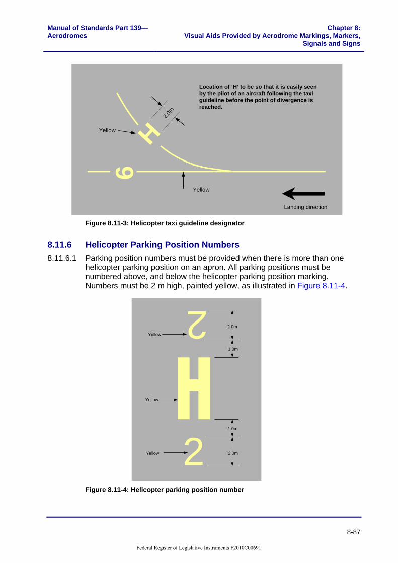
Manual of Standards Part 139—Aerodromes
Chapter 8:Visual Aids Provided by Aerodrome Markings, Markers,
Signals and Signs
8-87
6H
2.0m
Location of ‘H’ to be so that it is easily seen by the pilot of an aircraft following the taxi guideline before the point of divergence is reached.
Yellow
Yellow
Landing direction
Figure 8.11-3: Helicopter taxi guideline designator
8.11.6 Helicopter Parking Position Numbers 8.11.6.1 Parking position numbers must be provided when there is more than one
helicopter parking position on an apron. All parking positions must be numbered above, and below the helicopter parking position marking. Numbers must be 2 m high, painted yellow, as illustrated in Figure 8.11-4.
2.0m
2.02.0
2.0m
1.0m
2
2
1.0m
Yellow
Yellow
Yellow
Figure 8.11-4: Helicopter parking position number
Federal Register of Legislative Instruments F2010C00691

Chapter 8: Visual Aids Provided by Aerodrome Markings, Markers, Signals and Signs
Manual of Standards Part 139—Aerodromes
8-88
8.11.7 Helicopter Apron Edge Markings 8.11.7.1 Apron edge markings must be provided when it is necessary to clearly define
areas allocated specifically for helicopter parking. 8.11.7.2 On sealed, concrete or asphalt aprons, the edge marking must consist of two
continuous lines 0.15 m wide, 0.15 m apart, painted light blue. Additionally, the words ‘HELICOPTER ONLY’ must be painted in yellow, along the edge marking, outside the helicopter apron, and legible to pilots of approaching aircraft. The letters must be 0.5 m high, located 0.15 m from the helicopter apron edge marking. These words must be spaced at intervals not exceeding 50 m, along the helicopter apron edge marking, as shown below.
0.15m
0.15mHELICOPTER ONLY 0.5m
0.15m
Helicopter only side
0.15m
Yellow
Light blue
Figure 8.11-5: Helicopter apron edge markings
8.11.7.3 On gravel or natural surfaces, the apron must be marked using light blue cones; spaced at a minimum of 30 m, and a maximum of 60 m apart.
Section 8.12: Marking of Glider Runway Strips on an Aerodrome
8.12.1.1 When gliding operations are being conducted at an aerodrome, a signal consisting of a double white cross must be displayed in the signal circle. Details of the signal are illustrated in Figure 8.12-4, below.
8.12.1.2 Where the glider runway strip is located wholly or partly within an existing runway strip for powered aircraft, the width of the glider runway strip must be fixed on the one side by the edge of the runway for powered aircraft, and on the other by the existing runway strip markers adjusted as necessary, as shown below in Figure 8.12-1 and Figure 8.12-2.
Federal Register of Legislative Instruments F2010C00691

Manual of Standards Part 139—Aerodromes
Chapter 8:Visual Aids Provided by Aerodrome Markings, Markers,
Signals and Signs
8-89
8.12.1.3 Where a glider runway strip is located outside an existing runway strip for powered aircraft, the glider runway strip must be marked with boundary markers of a conspicuous colour other than white, as shown in Figure 8.12-3.
8.12.1.4 Where an end of a glider runway strip is not alongside the end of an existing runway strip for powered aircraft, an additional white double cross on a black background must be displayed 20 m in front of the glider strip end markers, as shown in Figure 8.12-2 and Figure 8.12-3.
Runway
Glider Runway Strip 15m
Figure 8.12-1: Glider runway strip taking up the full length of powered aircraft runway strip (no signal required)
Runway
Glider Runway Strip
20m
Glider Runway Strip
(see detail A)
Figure 8.12-2: Glider runway strip taking part of the powered aircraft runway strip
Markers shall be a conspicuous colour other than white
Runway
Glider Runway Strip
Figure 8.12-3: Glider runway strip outside an existing powered aircraft runway strip
Federal Register of Legislative Instruments F2010C00691

Chapter 8: Visual Aids Provided by Aerodrome Markings, Markers, Signals and Signs
Manual of Standards Part 139—Aerodromes
8-90
6m
1m
1m
12m
5m
White
Detail A
Figure 8.12-4: Detail of glider operations signal
Federal Register of Legislative Instruments F2010C00691