certification specifications and guidance material for ... · pdf filechapter l — visual...
TRANSCRIPT

Annex to ED Decision 2015/001/R
`
European Aviation Safety Agency
Certification Specifications
and
Guidance Material
for
Aerodromes Design
CS-ADR-DSN
Issue 2
29 January 20151
1 For the date of entry into force of this Amendment, kindly refer to Decision 2015/001/R in the Official Publication of the
Agency.
CONTENTS
Page 2 of 287
CONTENTS
CS–ADR-DSN — AERODROMES DESIGN
BOOK 1 — CERTIFICATION SPECIFICATIONS FOR AERODROMES ....................................... 5
CHAPTER A — GENERAL ................................................................................................. 5
CHAPTER B — RUNWAYS .............................................................................................. 13
CHAPTER C — RUNWAY END SAFETY AREA ..................................................................... 24
CHAPTER D — TAXIWAYS ............................................................................................. 26
CHAPTER E — APRONS ................................................................................................. 34
CHAPTER F — ISOLATED AIRCRAFT PARKING POSITION .................................................. 35
CHAPTER G — DE-ICING/ANTI-ICING FACILITIES............................................................ 36
CHAPTER H — OBSTACLE LIMITATION SURFACES ........................................................... 38
CHAPTER J — OBSTACLE LIMITATION REQUIREMENTS .................................................... 45
CHAPTER K — VISUAL AIDS FOR NAVIGATION (INDICATORS AND SIGNALLING DEVICES) ... 51
CHAPTER L — VISUAL AIDS FOR NAVIGATION (MARKINGS) ............................................. 53
CHAPTER M — VISUAL AIDS FOR NAVIGATION (LIGHTS) ................................................. 76
CHAPTER N — VISUAL AIDS FOR NAVIGATION (SIGNS) .................................................. 119
CHAPTER P — VISUAL AIDS FOR NAVIGATION (MARKERS) .............................................. 142
CHAPTER Q — VISUAL AIDS FOR DENOTING OBSTACLES ................................................ 144
CHAPTER R — VISUAL AIDS FOR DENOTING RESTRICTED USE AREAS .............................. 155
CHAPTER S — ELECTRICAL SYSTEMS ............................................................................ 158
CHAPTER T — AERODROME OPERATIONAL SERVICES, EQUIPMENT AND INSTALLATION ..... 165
CHAPTER U — COLOURS FOR AERONAUTICAL GROUND LIGHTS, MARKINGS, SIGNS AND
PANELS ..................................................................................................................... 168
BOOK 2 — GUIDANCE MATERIAL FOR AERODROMES ..................................................... 203
CHAPTER A — GENERAL .............................................................................................. 203
CHAPTER B — RUNWAYS ............................................................................................. 205
CHAPTER C — RUNWAY END SAFETY AREA .................................................................... 222
CHAPTER D — TAXIWAYS ............................................................................................ 227
CHAPTER E — APRONS ................................................................................................ 234
CHAPTER F — ISOLATED AIRCRAFT PARKING POSITION ................................................. 236
CHAPTER G — DE-ICING/ANTI-ICING FACILITIES........................................................... 237
CHAPTER H — OBSTACLE LIMITATION SURFACES .......................................................... 239
CHAPTER J — OBSTACLE LIMITATION REQUIREMENTS ................................................... 244
CHAPTER K — VISUAL AIDS FOR NAVIGATION (INDICATORS AND SIGNALLING DEVICES) .. 246
CHAPTER L — VISUAL AIDS FOR NAVIGATION (MARKINGS) ............................................ 248

CONTENTS
Page 3 of 287
CHAPTER M — VISUAL AIDS FOR NAVIGATION (LIGHTS) ................................................ 253
CHAPTER N — VISUAL AIDS FOR NAVIGATION (SIGNS) .................................................. 267
CHAPTER P — VISUAL AIDS FOR NAVIGATION (MARKERS) .............................................. 268
CHAPTER Q — VISUAL AIDS FOR DENOTING OBSTACLES ................................................ 270
CHAPTER R — VISUAL AIDS FOR DENOTING RESTRICTED USE AREAS .............................. 279
CHAPTER S — ELECTRICAL SYSTEMS ............................................................................ 282
CHAPTER T — AERODROME OPERATIONAL SERVICES, EQUIPMENT AND INSTALLATION ..... 284
CHAPTER U — COLOURS FOR AERONAUTICAL GROUND LIGHTS, MARKINGS, SIGNS AND
PANELS (APPENDIX 1) ................................................................................................ 287

Page 4 of 287
CS-ADR-DSN
Book 1
Certification Specifications
Aerodromes Design

CS-ADR-DSN — BOOK 1
CHAPTER A — GENERAL
Page 5 of 287
CERTIFICATION SPECIFICATIONS FOR AERODROMES
CHAPTER A — GENERAL
CS ADR-DSN.A.001 Applicability
The certification specifications of Book 1 and the related guidance material in Book 2 are applicable to aerodromes falling within the scope of the Regulation (EC) No 216/2008 (Basic Regulation).
CS ADR-DSN.A.002 Definitions
For the purposes of BOOKS 1 and 2, the following definitions should apply:
‘Accuracy’ means a degree of conformance between the estimated or measured value and the true value.
‘Aerodrome’ means a defined area (including any buildings, installations and equipment) on land or water or on a fixed offshore or floating structure intended to be used either wholly or in part for the arrival, departure and surface movement of aircraft.
‘Aerodrome beacon’ means an aeronautical beacon used to indicate the location of an aerodrome from the air.
‘Aerodrome elevation’ means the elevation of the highest point of the landing area.
‘Aerodrome equipment’ means any equipment, apparatus, appurtenance, software or accessory, that is used or intended to be used to contribute to the operation of aircraft at an aerodrome.
‘Aerodrome identification sign’ means a sign placed on an aerodrome to aid in identifying the aerodrome from the air.
‘Aerodrome operator’ means any legal or natural person, operating or proposing to operate one or more aerodromes.
‘Aerodrome reference point’ means the designated geographical location of an aerodrome.
‘Aeronautical beacon’ means an aeronautical ground light visible at all azimuths, either continuously or intermittently, to designate a particular point on the surface of the earth.
‘Aeronautical ground light’ means any light specially provided as an aid to air navigation, other than a light displayed on an aircraft.
‘Aeroplane’ means a power-driven heavier-than-air aircraft, deriving its lift in flight chiefly from aerodynamic reactions on surfaces which remain fixed under given conditions of flight;
‘Aeroplane reference field length’ means the minimum field length required for take-off at maximum certificated take-off mass, sea level, standard atmospheric conditions, still air and zero runway slope, as shown in the appropriate aeroplane flight manual prescribed by the certificating authority or equivalent data from the aeroplane manufacturer. Field length means balanced field length for aeroplanes, if applicable, or take-off distance in other cases.
‘Aircraft’ means a machine that can derive support in the atmosphere from the reactions of the air other than the reactions of the air against the earth’s surface.
‘Aircraft classification number (ACN)’ means the number expressing the relative effect of an aircraft on a pavement for a specified standard subgrade category.
‘Aircraft stand’ means a designated area on an apron intended to be used for parking an aircraft.

CS-ADR-DSN — BOOK 1
CHAPTER A — GENERAL
Page 6 of 287
‘Aircraft stand taxilane’ means a portion of an apron designated as a taxiway and intended to provide
access to aircraft stands only.
‘Apron’ means a defined area intended to accommodate aircraft for purposes of loading or unloading passengers, mail or cargo, fuelling, parking, or maintenance.
‘Apron taxiway’ means a portion of a taxiway system located on an apron and intended to provide a
through taxi-route across the apron.
‘Balked landing’ means a landing manoeuvre that is unexpectedly discontinued at any point below the obstacle clearance altitude/height (OCA/H).
‘Barrette’ means three or more aeronautical ground lights closely spaced in a transverse line so that from a distance they appear as a short bar of light.
‘Capacitor discharge light’ means a lamp in which high-intensity flashes of extremely short duration are produced by the discharge of electricity at high voltage through a gas enclosed in a tube.
‘Certification specifications’ mean technical standards adopted by the Agency indicating means to show compliance with Regulation (EC) No 216/2008 and its Implementing Rules and which can be used by an organisation for the purpose of certification.
‘Clearway’ means a defined rectangular area on the ground or water under the control of the appropriate entity, selected or prepared as a suitable area over which an aeroplane may make a portion of its initial climb to a specified height.
‘Critical Area’ means an area of defined dimensions extending about the ground equipment of a precision instrument approach within which the presence of vehicles or aircraft will cause unacceptable disturbance of the guidance signals.
‘Datum’ means any quantity or set of quantities that may serve as a reference or basis for the calculation of other quantities (ISO 19104).
‘Declared distances’ means:
— ‘Take-off run available (TORA)’ means the length of runway declared available and suitable for the
ground run of an aeroplane taking off.
— ‘Take-off distance available (TODA)’ means the length of the take-off run available plus the length of
the clearway if provided.
— ‘Accelerate-stop distance available (ASDA)’ means the length of the take-off run available plus the
length of the stopway if provided.
— ‘Landing distance available (LDA)’ means the length of runway which is declared available and
suitable for the ground run of an aeroplane landing.
‘De-icing/anti-icing facility’ means a facility where frost, ice, or snow is removed (de-icing) from the aeroplane to provide clean surfaces, and/or where clean surfaces of the aeroplane receive protection (anti-icing) against the formation of frost or ice and accumulation of snow or slush for a limited period of time.
‘De-icing/anti-icing pad’ means an area comprising an inner area for the parking of an aeroplane to receive de-icing/anti-icing treatment and an outer area for the manoeuvring of two or more mobile de-icing/anti-icing equipment.
‘Dependent parallel approaches’ means simultaneous approaches to parallel or near-parallel instrument runways where radar separation minima between aircraft on adjacent extended runway centre lines are prescribed.
‘Displaced threshold’ means a threshold not located at the extremity of a runway.

CS-ADR-DSN — BOOK 1
CHAPTER A — GENERAL
Page 7 of 287
‘Fixed light’ means a light having constant luminous intensity when observed from a fixed point.
‘Frangibility’ means the ability of an object to retain its structural integrity and stiffness up to a specified maximum load but when subject to a load greater than specified or struck by an aircraft will break, distort or yield in a manner designed to present minimum hazard to an aircraft.
‘Frangible object’ means an object of low mass designed to break, distort or yield on impact so as to present the minimum hazard to aircraft.
‘Graded area’ means that part of the runway strip cleared of all obstacles, except for specified items and
graded, intended to reduce the risk of damage to an aircraft running off the runway.
‘Hazard beacon’ means an aeronautical beacon used to designate a danger to air navigation.
‘Holding bay’ means a defined area where aircraft can be held, or bypassed to facilitate efficient surface movement of aircraft.
‘Holdover time’ means the estimated time during which the anti-icing fluid (treatment) will prevent the formation of ice and frost and the accumulation of snow on the protected (treated) surfaces of an aeroplane.
‘Identification beacon’ means an aeronautical beacon emitting a coded signal by means of which a particular point of reference can be identified.
‘Independent parallel approaches’ means simultaneous approaches to parallel or near-parallel instrument runways where radar separation minima between aircraft on adjacent extended runway centre lines are not prescribed.
‘Independent parallel departures’ means simultaneous departures from parallel or near-parallel instrument runways.
‘Instrument runway’ means one of the following types of runways intended for the operation of aircraft using instrument approach procedures:
1. ‘Non-precision approach runway’: an instrument runway served by visual aids and a non-visual aid providing at least directional guidance adequate for a straight-in approach.
2. ‘Precision approach runway, category I’: an instrument runway served by non-visual aids and visual aids, intended for operations with a decision height (DH) not lower than 60 m (200 ft) and either a visibility not less than 800 m or a runway visual range (RVR) not less than 550 m.
3. ‘Precision approach runway, category II’: an instrument runway served by non-visual aids and visual aids intended for operations with a decision height (DH) lower than 60 m (200 ft) but not lower than 30 m (100 ft) and a runway visual range (RVR) not less than 300 m.
4. ‘Precision approach runway, category III’: an instrument runway served by non-visual aids and visual aids to and along the surface of the runway and:
A — intended for operations with a decision height (DH) lower than 30 m (100 ft), or no decision height and a runway visual range (RVR) not less than 175 m;
B — intended for operations with a decision height (DH) lower than 15 m (50 ft), or no decision height and a runway visual range (RVR less than 175 m but not less than 50 m; and
C — intended for operations with no decision height (DH) and no runway visual range (RVR) limitations.
‘Intermediate holding position’ means a designated position intended for traffic control at which taxiing aircraft and vehicles should stop and hold until further cleared to proceed when so instructed by the aerodrome control tower.

CS-ADR-DSN — BOOK 1
CHAPTER A — GENERAL
Page 8 of 287
‘Isolated Aircraft Parking Position’ means an area suitable for the parking of an aircraft which is known or suspected to be the subject of unlawful interference, or for other reasons needs isolation from normal aerodrome activities.
‘Landing area’ means that part of a movement area intended for the landing or take-off of aircraft.
‘Landing direction indicator’ means a device to indicate visually the direction currently designated for landing and for take-off.
‘Manoeuvring area’ means that part of an aerodrome to be used for the take-off, landing and taxiing of aircraft, excluding aprons.
‘Marker’ means an object displayed above ground level in order to indicate an obstacle or delineate a boundary.
‘Marking’ means a symbol or group of symbols displayed on the surface of the movement area in order to convey aeronautical information.
‘Movement area’ means that part of an aerodrome to be used for the take-off, landing and taxiing of aircraft, consisting of the manoeuvring area and the apron(s).
‘Non-instrument runway’ means a runway intended for the operation of aircraft using visual approach procedures.
‘Obstacle’ means all fixed (whether temporary or permanent) and mobile objects, or parts thereof, that: — are located on an area intended for the surface movement of aircraft; or
— extend above a defined surface intended to protect aircraft in flight; or
— stand outside those defined surfaces and that have been assessed as being a hazard to air navigation.
‘Obstacle free zone (OFZ)’ means the airspace above the inner approach surface, inner transitional surfaces, and balked landing surface and that portion of the strip bounded by these surfaces, which is not penetrated by any fixed obstacle other than a low-mass and frangibly mounted one required for air navigation purposes.
‘Obstacle limitation surface’ means a surface that defines the limits to which objects may project into the airspace.
‘Obstacle protection surface’ means a surface established for visual approach slope indicator system above which objects or extensions of existing objects shall not be permitted except when, in the opinion of the appropriate authority, the new object or extension would be shielded by an existing immovable object;.
‘Operator’ means any legal or natural person, operating or proposing to operate one or more aircraft or one or more aerodromes.
‘Paved runway’ means a runway with a hard surface that is made up of engineered and manufactured materials bound together so it is durable and either flexible or rigid.
‘Pavement classification number (PCN)’ means a number expressing the bearing strength of a pavement for unrestricted operations.
‘Precision approach runway’, see ‘instrument runway’.
‘Primary runway(s)’ means runway(s) used in preference to others whenever conditions permit.
‘Rapid exit taxiway’ means a taxiway connected to a runway at an acute angle and designed to allow
landing aeroplanes to turn off at higher speeds than are achieved on other exit taxiways thereby minimising
runway occupancy times;
‘Road’ means an established surface route on the movement area meant for the exclusive use of vehicles.

CS-ADR-DSN — BOOK 1
CHAPTER A — GENERAL
Page 9 of 287
‘Road-holding position’ means a designated position at which vehicles may be required to hold.
‘Runway’ means a defined rectangular area on a land aerodrome prepared for the landing and take-off of aircraft.
‘Runway end safety area (RESA)’ means an area symmetrical about the extended runway centre line and adjacent to the end of the strip primarily intended to reduce the risk of damage to an aeroplane undershooting or overrunning the runway.
‘Runway guard lights’ means a light system intended to caution pilots or vehicle drivers that they are about to enter an active runway.
‘Runway-holding position’ means a designated position intended to protect a runway, an obstacle limitation surface, or an ILS/MLS critical/sensitive area at which taxiing aircraft and vehicles should stop and hold, unless otherwise authorised by the aerodrome control tower.
‘Runway strip’ means a defined area including the runway and stopway, if provided, intended: — to reduce the risk of damage to aircraft running off a runway; and
— to protect aircraft flying over it during take-off or landing operations.
‘Runway turn pad’ means a defined area on a land aerodrome adjacent to a runway for the purpose of completing a 180-degree turn on a runway.
‘Runway type’ means instrument runway or non-instrument runway.
‘Runway visual range (RVR)’ means the range over which the pilot of an aircraft on the centre line of a runway can see the runway surface markings or the lights delineating the runway or identifying its centre line.
‘Sensitive Area’ means an area extending beyond the Critical Area where the parking and/or movement of aircraft or vehicles will affect the guidance signal to the extent that it may be rendered unacceptable to aircraft using the signal.
‘Shoulder’ means an area adjacent to the edge of a pavement so prepared as to provide a transition between the pavement and the adjacent surface.
‘Sign’: — Fixed message sign means a sign presenting only one message;
— Variable message sign means a sign capable of presenting several predetermined messages or no
message, as applicable.
‘Signal area’ means an area on an aerodrome used for the display of ground signals.
‘Slush’ means water-saturated snow which with a heel-and-toe slap-down motion against the ground will be displaced with a splatter; specific gravity: 0.5 up to 0.8.
‘Snow’ (on the ground):
— Dry snow means snow which can be blown if loose or, if compacted by hand, will fall apart again upon release; specific gravity: up to but not including 0.35.
— Wet snow means snow which, if compacted by hand, will stick together and tend to or form a snowball; specific gravity: 0.35 up to but not including 0.5.
— Compacted snow means snow which has been compressed into a solid mass that resists further compression and will hold together or break up into lumps if picked up; specific gravity: 0.5 and over.
‘Stopway’ means a defined rectangular area on the ground at the end of take-off run available prepared as a suitable area in which an aircraft can be stopped in the case of an abandoned take-off.
CS-ADR-DSN — BOOK 1
CHAPTER A — GENERAL
Page 10 of 287
‘Surface friction’ means the resistance offered to the movement of one body past a surface with which it is in contact.
‘Switch-over time (light)’ means the time required for the actual intensity of a light measured in a given direction to fall from 50 % and recover to 50 % during a power supply changeover, when the light is being operated at intensities of 25 % or above.
‘Take-off runway’ means a runway intended for take-off only.
‘Taxiway’ means a defined path on a land aerodrome established for the taxiing of aircraft and intended to provide a link between one part of the aerodrome and another, including: — Aircraft stand taxilane;
— Apron taxiway;
— Rapid exit taxiway.
‘Taxiway intersection’ means a junction of two or more taxiways.
‘Taxiway strip’ means an area including a taxiway intended to protect an aircraft operating on the taxiway and to reduce the risk of damage to an aircraft accidentally running off the taxiway.
‘Threshold’ means the beginning of that portion of the runway usable for landing.
‘Touchdown zone’ means the portion of a runway, beyond the threshold, where landing aeroplanes are intended to first contact the runway.
‘Visual aids’ means indicators and signalling devices, markings, lights, signs and markers or combinations thereof.
‘Visual approach slope indicator system’ means a system of lights arranged to provide visual descent guidance information during the approach to a runway.

CS-ADR-DSN — BOOK 1
CHAPTER A — GENERAL
Page 11 of 287
CS ADR-DSN.A.005 Aerodrome reference code
(a) An aerodrome reference code, consisting of a code number and letter which is selected for aerodrome planning purposes, should be determined in accordance with the characteristics of the aeroplane for which an aerodrome facility is intended.
(b) The aerodrome reference code numbers and letters should have the meanings assigned to them in Table A-1.
(c) The code number for element 1 should be determined from Table A-1, column 1, selecting the code number corresponding to the highest value of the aeroplane reference field lengths of the aeroplanes for which the runway is intended. The determination of the aeroplane reference field length is solely for the selection of a code number and is not intended to influence the actual runway length provided.
(d) The code letter for element 2 should be determined from Table A-1, column 3, by selecting the code letter which corresponds to the greatest wingspan, or the greatest outer main gear wheel span whichever gives the more demanding code letter of the aeroplanes for which the facility is intended.
CODE ELEMENT ONE CODE ELEMENT TWO
Code
Number
Aeroplane reference field
length
Code
Letter Wing Span
Outer Main Gear Wheel
Spana
1 Less than 800 m A Up to but not including
15 m
Up to but not including
4.5 m
2 800 m up to but not
including 1 200 m
B 15 m up to but not
including 24 m
4.5 m up to but not
including 6 m
3 1 200 m up to but not
including 1 800 m
C 24 m up to but not
including 36 m
6 m up to but not
including 9 m
4 1 800 m and over D 36 m up to but not
including 52 m
9 m up to but not
including 14 m
E 52 m up to but not
including 65 m
9 m up to but not
including 14 m
F 65 m up to but not
including 80 m
14 m up to but not
including 16 m
a Distance between the outside edges of the main gear wheels
Table A-1 Aerodrome reference code

CS-ADR-DSN — BOOK 1
CHAPTER A — GENERAL
Page 12 of 287
CS ADR-DSN.A.010
Intentionally blank
CS-ADR-DSN — BOOK 1
CHAPTER B — RUNWAYS
Page 13 of 287
CHAPTER B — RUNWAYS
CS ADR-DSN.B.015 Number, siting and orientation of runways
The number and orientation of runways at an aerodrome should be such that the usability factor of the aerodrome is optimised taking into account that safety is not compromised.
CS ADR-DSN.B.020 Choice of maximum permissible crosswind components
Intentionally blank
CS ADR-DSN.B.025 Data to be used
Intentionally blank
CS ADR-DSN.B.030 Runway threshold
(a) A threshold should be provided on a runway.
(b) A threshold needs not to be provided on a take-off runway.
(c) A threshold should be located at the extremity of a runway unless operational considerations justify the choice of another location.
(d) When it is necessary to displace a threshold, either permanently or temporarily, from its normal location, account should be taken of the various factors which may have a bearing on the location of the threshold.
(e) When the threshold is displaced, the threshold location should be measured at the inner edge of the threshold marking (the transverse stripe across the runway).
CS ADR-DSN.B.035 Actual length of runway and declared distances
(a) The length of a runway should provide declared distances adequate to meet the operational requirements for the aircraft which the runway is intended to serve.
(b) The following distances should be calculated to the nearest metre for each runway:
(1) Take-off run available;
(2) Take-off distance available;
(3) Accelerate-stop distance available; and
(4) Landing distance available.
(c) The length of the runway is measured from the start of the runway pavement or where a transverse stripe marking is provided to indicate threshold displacement, at the inner edge of the transverse stripe across the runway.
CS ADR-DSN.B.040 Runways with stopways or clearways
The length(s) of a stopway or clearway, where provided, should be of adequate distance to meet the operational requirements for the aircraft which the runway is intended to serve.

CS-ADR-DSN — BOOK 1
CHAPTER B — RUNWAYS
Page 14 of 287
CS ADR-DSN.B.045 Width of runways
(a) The width of a runway should be not less than the appropriate dimension specified in the Table B-1.
Code letter
Code Number
A B C D E F
1a 18 m 18 m 23 m — — —
2a 23 m 23 m 30 m — — —
3 30 m 30 m 30 m 45 m — —
4 — — 45 m 45 m 45 m 60 m
a The width of a precision approach runway should be not less than 30 m where the code number is 1 or 2.
Table B-1. Width of runway
(b) The width of the runway should be measured at the outside edge of the runway side stripe marking where provided, or the edge of the runway.
CS ADR-DSN.B.050 Minimum distance between parallel non-instrument runways
(a) Where parallel non-instrument runways are intended for simultaneous use, the minimum distance between their centre lines should be:
(1) 210 m where the higher code number is 3 or 4;
(2) 150 m where the higher code number is 2; and
(3) 120 m where the higher code number is 1.
CS ADR-DSN.B.055 Minimum distance between parallel instrument runways
(a) Where parallel instrument runways are intended for simultaneous use, the minimum distance between their centre lines should be:
(1) 1 035 m for independent parallel approaches;
(2) 915 m for dependent parallel approaches;
(3) 760 m for independent parallel departures; and
(4) 760 m for segregated parallel operations.
(b) Apart from provided in (a) above, for segregated parallel operations the specified minimum distance:
(1) should be decreased by 30 m for each 150 m that the arrival runway is staggered toward the
arriving aircraft, to a minimum of 300 m; and
(2) should be increased by 30 m for each 150 m that the arrival runway is staggered away from
the arriving aircraft.
CS-ADR-DSN — BOOK 1
CHAPTER B — RUNWAYS
Page 15 of 287
(c) Other combinations of minimum distances should apply taking into account ATM and operational aspects.
CS ADR-DSN.B.060 Longitudinal slopes of runways
(a) The safety objective of limiting the longitudinal runway slope is to enable stabilized and safe use of runway by an aircraft.
(b) The slope computed by dividing the difference between the maximum and minimum elevation along the runway centre line by the runway length should not exceed:
(1) 1 % where the code number is 3 or 4; and
(2) 2 % where the code number is 1 or 2.
(c) Along no portion of a runway should the longitudinal slope exceed:
(1) 1.25 % where the code number is 4, except that for the first and last quarter of the length of the runway where the longitudinal slope should not exceed 0.8 %;
(2) 1.5 % where the code number is 3, except that for the first and last quarter of the length of a precision approach runway category II or III where the longitudinal slope should not exceed 0.8 %; and
(3) 2 % where the code number is 1 or 2.
CS ADR-DSN.B.065 Longitudinal slope changes on runways
(a) The safety objective of limiting the longitudinal runway slope changes is to avoid damage of aircraft and to enable safe use of runway by an aircraft.
(b) Where slope changes cannot be avoided, a slope change between two consecutive slopes should not exceed:
(1) 1.5 % where the code number is 3 or 4; and
(2) 2 % where the code number is 1 or 2.
(c) The transition from one slope to another should be accomplished by a curved surface with a rate of change not exceeding:
(1) 0.1 % per 30 m (minimum radius of curvature of 30 000 m) where the code number is 4;
(2) 0.2 % per 30 m (minimum radius of curvature of 15 000 m) where the code number is 3; and
(3) 0.4 % per 30 m (minimum radius of curvature of 7 500 m) where the code number is 1 or 2.
CS ADR-DSN.B.070 Sight distance for slopes on runways
(a) The safety objective of minimum runway sight distance values is to achieve the necessary visibility to enable safe use of runway by an aircraft.
(b) Where slope changes on runways cannot be avoided, they should be such that there should be an unobstructed line of sight from:
(1) any point 3 m above a runway to all other points 3 m above the runway within a distance of at least half the length of the runway where the code letter is C, D, E, or F;

CS-ADR-DSN — BOOK 1
CHAPTER B — RUNWAYS
Page 16 of 287
(2) any point 2 m above a runway to all other points 2 m above the runway within a distance of at least half the length of the runway where the code letter is B; and
(3) any point 1.5 m above a runway to all other points 1.5 m above the runway within a distance of at least half the length of the runway where the code letter is A.
CS ADR-DSN.B.075 Distance between slope changes on runways
Undulations or appreciable changes in slopes located close together along a runway should be avoided. The distance between the points of intersection of two successive curves should not be less than:
(a) the sum of the absolute numerical values of the corresponding slope changes multiplied by the appropriate value as follows:
(1) 30 000 m where the code number is 4;
(2) 15 000 m where the code number is 3; and
(3) 5 000 m where the code number is 1 or 2; or
(b) 45 m;
whichever is greater.
CS ADR-DSN.B.080 Transverse slopes on runways
(a) The safety objective of runway transverse slopes is to promote the most rapid drainage of water
from the runway.
(b) To promote the most rapid drainage of water, the runway surface should be cambered, except where a single crossfall from high to low in the direction of the wind most frequently associated with rain would ensure rapid drainage. The transverse slope should be:
(1) not less than 1 % and not more than 1.5 % where the code letter is C, D, E or F; and;
(2) not less than 1 % and not more than 2 % where the code letter is A or B;
except at runway or taxiway intersections where flatter slopes may be necessary.
(c) For a cambered surface, the transverse slope on each side of the centre line should be symmetrical.
(d) The transverse slope should be substantially the same throughout the length of a runway except at an intersection with another runway or a taxiway where an even transition should be provided taking account of the need for adequate drainage.
CS ADR-DSN.B.085 Runway strength
The runway should be of sufficient strength to support normal operations of the most demanding aircraft without risk of damage either to the aeroplane or the runway.
CS ADR-DSN.B.090 Surface of runways
(a) The surface of a runway should be constructed without irregularities that would result in loss in friction characteristics or otherwise adversely affect the take-off or landing of an aeroplane.
(b) The surface of a paved runway should be constructed so as to provide good friction characteristics when the runway is wet.
(c) The average surface texture depth of a new surface should be not less than 1.0 mm.

CS-ADR-DSN — BOOK 1
CHAPTER B — RUNWAYS
Page 17 of 287
(d) If the surface is grooved or scored, the grooves or scorings should be either perpendicular to the runway centre line or parallel to non-perpendicular transverse joints where applicable.
SECTION 1 — RUNWAY TURN PADS
CS ADR-DSN.B.095 Runway turn pads
(a) The safety objective of the runway turn pad is to facilitate a safe 180-degree turn by aeroplanes on runway ends that are not served by a taxiway or taxiway turnaround.
(b) Where the end of a runway is not served by a taxiway or a taxiway turnaround, and if required, a runway turn pad should be provided to facilitate a 180-degree turn of aeroplanes.
(c) The design of a runway turn pad should be such that when the cockpit of the most demanding aircraft for which the turn pad is intended remains over the turn pad marking, the clearance distance between any wheel of the aeroplane landing gear and the edge of the turn pad should be not less than that given by the following tabulation:
Code letter Clearance
A 1.5 m
B 2.25 m
C 3 m if the turn pad is intended to be used by aeroplanes with a wheel base less than
18 m; or
4.5 m if the turn pad is intended to be used by aeroplanes with a wheel base equal to
or greater than 18 m.
D 4.5 m
E 4.5 m
F 4.5 m
Note: Wheel base means the distance from the nose gear to the geometric centre of the main gear.
(d) The runway turn pad should be located on either the left or right side of the runway and adjoining the runway pavement at both ends of the runway and at some intermediate locations where deemed necessary.
(e) The intersection angle of the runway turn pad with the runway should not exceed 30 degrees.
(f) The nose wheel steering angle to be used in the design of the runway turn pad should not exceed 45 degrees.
CS ADR-DSN.B.100 Slopes on runway turn pads
The longitudinal and transverse slopes on a runway turn pad should be sufficient to prevent the accumulation of water on the surface and facilitate rapid drainage of surface water. The slopes should be the same as those on the adjacent runway pavement surface.
CS ADR-DSN.B.105 Strength of runway turn pads
The strength of a runway turn pad should be compatible with the adjoining runway which it serves, due consideration being given to the fact that the turn pad should be subjected to slow-moving traffic making
CS-ADR-DSN — BOOK 1
CHAPTER B — RUNWAYS
Page 18 of 287
hard turns and consequent higher stresses on the pavement.
CS ADR-DSN.B.110 Surface of runway turn pads
(a) The surface of a runway turn pad should not have surface irregularities that may cause damage to an aeroplane using the turn pad.
(b) The surface of a runway turn pad should be constructed or resurfaced to provide friction characteristics compatible with the runway friction characteristics.
CS ADR-DSN.B.115 Width of shoulders for runway turn pads
The runway turn pads should be provided with shoulders of such width as is necessary to prevent surface erosion by the jet blast of the most demanding aircraft for which the turn pad is intended and any possible foreign object damage to the aeroplane engines.
CS ADR-DSN.B.120 Strength of shoulders for runway turn pads
The strength of runway turn pad shoulders should be capable of withstanding the occasional passage of the most demanding aircraft it is designed to serve without inducing structural damage to the aircraft and to the supporting ground vehicles that may operate on the shoulder.
SECTION 2 — RUNWAY SHOULDERS
CS ADR-DSN.B.125 Runway shoulders
(a) The safety objective of runway shoulder is that it should be so constructed as to mitigate any hazard to an aircraft running off the runway or stopway or to avoid the ingestion of loose stones or other objects by turbine engines
(b) Runway shoulders should be provided for a runway where the code letter is D or E, and the runway width is less than 60 m.
(c) Runway shoulders should be provided for a runway where the code letter is F.
CS ADR-DSN.B.130 Slopes on runway shoulders
(a) The safety objective of runway shoulder transverse slopes is to promote the most rapid drainage of
water from the runway and runway shoulder.
(b) The surface of the paved shoulder that abuts the runway should be flush with the surface of the runway and its transverse slope should not exceed 2.5 %.
CS ADR-DSN.B.135 Width of runway shoulders
The runway shoulders should extend symmetrically on each side of the runway so that the overall width of the runway and its shoulders is not less than:
(a) 60 m where the code letter is D or E; and
(b) 75 m where the code letter is F.
CS ADR-DSN.B.140 Strength of runway shoulders
A runway shoulder should be prepared or constructed so as to be capable, in the event of an aeroplane running off the runway, of supporting the aeroplane without inducing structural damage to the aeroplane
CS-ADR-DSN — BOOK 1
CHAPTER B — RUNWAYS
Page 19 of 287
and of supporting ground vehicles which may operate on the shoulder.
CS ADR-DSN.B.145 Surface of runway shoulders
The surface of a runway shoulder should be prepared so as to resist erosion and prevent the ingestion of
the surface material by aeroplane engines.
SECTION 3 — RUNWAY STRIP
CS ADR-DSN.B.150 Runway strip to be provided
A runway and any associated stopways should be included in a strip.
CS ADR-DSN.B.155 Length of runway strip
A strip should extend before the threshold and beyond the end of the runway or stopway for a distance of at least:
(a) 60 m where the code number is 2, 3, or 4;
(b) 60 m where the code number is 1 and the runway is an instrument one; and
(c) 30 m where the code number is 1 and the runway is a non-instrument one.
CS ADR-DSN.B.160 Width of runway strip
(a) The safety objective of the runway strip is to reduce the probability of damage to an aircraft accidentally running off the runway, to protect aircraft flying over it when taking-off or landing and to enable safe use by rescue and firefighting vehicles’.
(b) A strip including a precision approach runway should extend laterally to a distance of at least:
(1) 150 m where the code number is 3 or 4; and
(2) 75 m where the code number is 1 or 2; on each side of the centre line of the runway and its extended centre line throughout the length of the strip.
(c) A strip including a non-precision approach runway should extend laterally to a distance of at least:
(1) 150 m where the code number is 3 or 4; and
(2) 75 m where the code number is 1 or 2;
on each side of the centre line of the runway and its extended centre line throughout the length of the strip.
(d) A strip including a non-instrument runway should extend on each side of the centre line of the runway and its extended centre line throughout the length of the strip, to a distance of at least:
(1) 75 m where the code number is 3 or 4;
(2) 40 m where the code number is 2; and
(3) 30 m where the code number is 1.

CS-ADR-DSN — BOOK 1
CHAPTER B — RUNWAYS
Page 20 of 287
CS ADR-DSN.B.165 Objects on runway strips
(a) An object situated on a runway strip which may endanger aeroplanes should be regarded as an obstacle and should, as far as practicable, be removed.
(b) No fixed object, other than visual aids required for air navigation or for aircraft safety purposes and satisfying the relevant frangibility requirement in Chapter T, should be permitted on a runway strip:
(1) within 77.5 m of the runway centre line of a precision approach runway category I, II or III where the code number is 4 and the code letter is F; or
(2) within 60 m of the runway centre line of a precision approach runway category I, II or III where the code number is 3 or 4;or
(3) within 45 m of the runway centre line of a precision approach runway category I where the code number is 1 or 2.
(c) To eliminate a buried vertical surface, a slope should be provided which extends from the top of the
construction to not less than 0.3 m below ground level. The slope should be no greater than 1:10.
(d) No mobile object should be permitted on this part of the runway strip during the use of the runway
for landing or take-off.
CS ADR-DSN.B.170
intentionally blank
CS ADR-DSN.B.175 Grading of runway strips
(a) That portion of a strip of an instrument runway within a distance of at least:
(1) 75 m where the code number is 3 or 4; and
(2) 40 m where the code number is 1 or 2;
from the centre line of the runway and its extended centre line should provide a graded area for aeroplanes which the runway is intended to serve in the event of an aeroplane running off the runway.
(b) That portion of a strip of a non-instrument runway within a distance of at least:
(1) 75 m where the code number is 3 or 4;
(2) 40 m where the code number is 2; and
(3) 30 m where the code number is 1;
from the centre line of the runway and its extended centre line should provide a graded area for aeroplanes which the runway is intended to serve in the event of an aeroplane running off the runway.
(c) The surface of that portion of a strip that abuts a runway, shoulder, or stopway should be flush with the surface of the runway, shoulder, or stopway.
(d) That portion of a strip to at least 30 m before a threshold should be prepared against blast erosion in order to protect a landing aeroplane from the danger of an exposed edge.

CS-ADR-DSN — BOOK 1
CHAPTER B — RUNWAYS
Page 21 of 287
CS ADR-DSN.B.180 Longitudinal slopes on runway strips
(a) The safety objective of longitudinal runway strip slope is to define maximum gradient values that should not interfere with the safe use of the runway strip by an aircraft.
(b) A longitudinal slope along that portion of a strip to be graded should not exceed:
(1) 1.5 % where the code number is 4;
(2) 1.75 % where the code number is 3; and
(3) 2 % where the code number is 1 or 2.
(c) Longitudinal slope changes on that portion of a strip to be graded should be as gradual as practicable, and abrupt changes or sudden reversals of slopes should be avoided.
CS ADR-DSN.B.185 Transverse slopes on runway strips
(a) Transverse slopes on that portion of a strip to be graded should be adequate to prevent the accumulation of water on the surface but should not exceed:
(1) 2.5 % where the code number is 3 or 4; and
(2) 3 % where the code number is 1 or 2;
except that to facilitate drainage from the slope for the first 3 m outward from the runway, shoulder
or stopway edge should be negative as measured in the direction away from the runway and may be
as great as 5 %.
(b) The transverse slopes of any portion of a strip beyond that to be graded should not exceed an upward slope of 5 % as measured in the direction away from the runway.
CS ADR-DSN.B.190 Strength of runway strips
(a) That portion of a strip of an instrument runway within a distance of at least:
(1) 75 m where the code number is 3 or 4; and
(2) 40 m where the code number is 1 or 2;
from the centre line of the runway and its extended centre line should be prepared or constructed so as to minimise hazards arising from differences in load-bearing capacity to aeroplanes which the runway is intended to serve in the event of an aeroplane running off the runway.
(b) That portion of a strip containing a non-instrument runway within a distance of at least:
(1) 75 m where the code number is 3 or 4;
(2) 40 m where the code number is 2; and
(3) 30 m where the code number is 1;
from the centre line of the runway and its extended centre line should be prepared or constructed so as to minimise hazards arising from differences in load-bearing capacity to aeroplanes which the runway is intended to serve in the event of an aeroplane running off the runway.

CS-ADR-DSN — BOOK 1
CHAPTER B — RUNWAYS
Page 22 of 287
SECTION 4 — CLEARWAYS, STOPWAYS AND RADIO ALTIMETER OPERATING AREA
CS ADR-DSN.B.195 Clearways
(a) The inclusion of detailed specifications for clearways in this section is not intended to imply that a clearway has to be provided.
(b) Location of clearways:
The origin of a clearway should be at the end of the take-off run available.
(c) Length of clearways
The length of a clearway should not exceed half the length of the take-off run available.
(d) Width of clearways:
A clearway should extend laterally to a distance of at least 75 m on each side of the extended centre line of the runway.
(e) Slopes on clearways:
The ground in a clearway should not project above a plane having an upward slope of 1.25 %, the
lower limit of this plane being a horizontal line which:
(1) is perpendicular to the vertical plane containing the runway centre line; and
(2) passes through a point located on the runway centre line at the end of the take-off run available.
(f) An object situated on a clearway which may endanger aeroplanes in the air should be regarded as an obstacle and should be removed.
CS ADR-DSN.B.200 Stopways
(a) The inclusion of detailed specifications for stopways in this section is not intended to imply that a stopway has to be provided.
(b) Width of stopways:
A stopway should have the same width as the runway with which it is associated.
(c) Slopes on stopways:
Slopes and changes in slope on a stopway, and the transition from a runway to a stopway, should
comply with the specifications of CS ADR-DSN.B.060 to CS ADR-DSN.B.080 for the runway with which
the stopway is associated except that:
(1) the limitation in CS ADR-DSN.B.060(b) of a 0.8 per cent slope for the first and last quarter of
the length of a runway need not be applied to the stopway; and
(2) at the junction of the stopway and runway and along the stopway the maximum rate of slope
change may be 0.3 per cent per 30 m (minimum radius of curvature of 10 000 m) for a runway
where the code number is 3 or 4.
(d) Strength of stopways:
CS-ADR-DSN — BOOK 1
CHAPTER B — RUNWAYS
Page 23 of 287
A stopway should be prepared or constructed so as to be capable, in the event of an abandoned take-off, of supporting the aeroplane which the stopway is intended to serve without inducing structural damage to the aeroplane.
(e) Surface of stopways:
The surface of a paved stopway should be constructed so as to provide a good coefficient of friction to be compatible with that of the associated runway when the stopway is wet.
CS ADR-DSN.B.205 Radio altimeter operating area
(a) A radio altimeter operating area should be established in the pre-threshold area of a precision approach runway category II and III, and where practicable, in the pre-threshold area of a precision approach runway category I.
(b) Length of the area:
A radio altimeter operating area should extend before the threshold for a distance of at least 300 m.
(c) Width of the area:
A radio altimeter operating area should extend laterally, on each side of the extended centre line of the runway, to a distance of 60 m, except that, when special circumstances so warrant, the distance may be reduced to no less than 30 m if an safety assessment indicates that such reduction would not affect the safety of operations of aircraft.

CS–ADR-DSN — BOOK 1
CHAPTER C — RUNWAY END SAFETY AREA
Page 24 of 287
CHAPTER C — RUNWAY END SAFETY AREA
CS ADR-DSN.C.210 Runway End Safety Areas
(a) The safety objective of the runway end safety area (RESA) is to minimise risks to aircraft and their occupants when an aeroplane overruns or undershoots a runway.
(b) A runway end safety area should be provided at each end of a runway strip where:
(1) the code number is 3 or 4; and
(2) the code number is 1 or 2 and the runway is an instrument one.
CS ADR-DSN.C.215 Dimensions of runway end safety areas
(a) Length of RESA
A runway end safety area should extend from the end of a runway strip to a distance of at least 90 m and, as far as practicable, extend to a distance of:
(1) 240 m where the code number is 3 or 4 and
(2) 120 m where the code number is 1 or 2 and the runway is an instrument one;
(b) Notwithstanding the provisions in (a) above, the length of the runway end safety area may be reduced where an arresting system is installed, based on the design specifications of the system.
(c) Width of RESA
The width of a runway end safety area should be at least twice that of the associated runway and, wherever practicable, be equal to that of the graded portion of the associated runway strip.
CS ADR-DSN.C.220 Objects on runway end safety areas
No fixed object, other than equipment and installations required for air navigation or for aeroplane safety purposes and satisfying the relevant frangibility requirement CS ADR-DSN.T.910, should be permitted on a runway end safety area. The detailed requirements for siting objects on a RESA are in CS ADR-DSN.T.915.
CS ADR-DSN.C.225 Clearing and grading of runway end safety areas
A runway end safety area should provide a cleared and graded area for aeroplanes which the runway is intended to serve in the event of an aeroplane undershooting or overrunning the runway.
CS ADR-DSN.C.230 Slopes on runway end safety areas
(a) Longitudinal slopes
(1) The slopes of a runway end safety area should be such that no part of the runway end safety area penetrates the approach or take-off climb surface.
(2) The longitudinal slopes of a runway end safety area should not exceed a downward slope of 5 %. Longitudinal slope changes should be as gradual as practicable, and abrupt changes or sudden reversals of slopes should be avoided.
(b) Transverse slopes
The transverse slopes of a runway end safety area should not exceed an upward or downward slope of 5 %. Transitions between differing slopes should be as gradual as practicable.

CS–ADR-DSN — BOOK 1
CHAPTER C — RUNWAY END SAFETY AREA
Page 25 of 287
CS ADR-DSN.C.235 Strength of runway end safety areas
Intentionally blank

CS-ADR-DSN — BOOK 1
CHAPTER D — TAXIWAYS
Page 26 of 287
CHAPTER D — TAXIWAYS
CS ADR-DSN.D.240 Taxiways general
Unless otherwise indicated, the requirements in Chapter D - Taxiways are applicable to all types of
taxiways.
(a) The design of a taxiway should be such that, when the cockpit of the aeroplane for which the taxiway is intended, remains over the taxiway centre line markings, the clearance distance between the outer main wheel of the aeroplane and the edge of the taxiway should be not less than that given by the following tabulation:
Code letter Clearance
A 1.5 m
B 2.25 m
C 3 m if the taxiway is intended to be used by aeroplanes with a wheel base less than 18 m; or
4.5 m if the taxiway is intended to be used by aeroplanes with a wheel base equal to or greater than 18 m.
D 4.5 m
E 4.5 m
F 4.5 m
CS ADR-DSN.D.245 Width of taxiways
A straight portion of a taxiway should have a width of not less than that given by the following tabulation:
Code letter Taxiway width
A 7.5 m
B 10.5 m
C 15 m if the taxiway is intended to be used by aeroplanes with a wheel base less than 18 m; or
18 m if the taxiway is intended to be used by aeroplanes with a wheel base equal to or greater than 18 m
D 18 m if the taxiway is intended to be used by aeroplanes with an outer main gear wheel span of less than 9 m; or
23 m if the taxiway is intended to be used by aeroplanes with an outer main gear wheel span equal to or greater than 9 m.
E 23 m
F 25 m

CS-ADR-DSN — BOOK 1
CHAPTER D — TAXIWAYS
Page 27 of 287
CS ADR-DSN.D.250 Taxiways curves
(a) Changes in direction of taxiways should be as few and small as possible. The radii of the curves should be compatible with the manoeuvring capability and normal taxiing speeds of the aeroplanes for which the taxiway is intended.
(b) The design of the curve should be such that when the cockpit of the aeroplane for which the taxiway is intended remains over the taxiway centre line markings, the clearance distance between the outer main wheels of the aeroplane and the edge of the taxiway should be not less than those specified in CS ADR-DSN.D.240.
CS ADR-DSN.D.255 Junction and intersection of taxiways
(a) To facilitate the movement of aeroplanes, fillets should be provided at junctions and intersections of taxiways with runways, aprons, and other taxiways.
(b) The design of the fillets should ensure that the minimum wheel clearances specified in CS ADR-DSN.D.240 are maintained when aeroplanes are manoeuvring through the junctions or intersections.
CS ADR-DSN.D.260 Taxiway minimum separation distance
(a) The safety objective of minimum taxi separation distances is to allow safe use of taxiways and aircraft stand taxilanes to prevent possible collision with other aeroplanes operating on adjacent runways or taxiways, or collision with adjacent objects.
(b) The separation distance between the centre line of a taxiway and the centre line of a runway, the centre line of a parallel taxiway or an object should not be less than the appropriate dimension specified in Table D-1.
Distance between taxiway centre line and runway centre line (metres)
Taxiway centre line to taxiway centre line (metres)
Taxiway, other than
aircraft stand
taxilane, centre line to object (metres)
Aircraft stand
taxilane centre line to aircraft stand
taxilane centre line (metres)
Aircraft stand
taxilane centre line to object (metres)
Instrument runways Code number
Non-instrument runways Code number
Code letter
1 2 3 4 1 2 3 4
(1) (2) (3) (4) (5) (6) (7) (8) (9) (10)
(11)
(12) (13)
A 82.5 82.5 — — 37.5 47.5 — — 23 15.5 19.5 12
B 87 87 — — 42 52 — — 32 20 28.5 16.5
C — — 168 — — — 93 44 26 40.5 22.5
D — — 176 176 — — 101 101 63 37 59.5 33.5
E — — — 182.5 — — — 107.5 76 43.5 72.5 40
F — — — 190 — — — 115 91 51 87.5 47.5
Note 1.— The separation distances shown in columns (2) to (9) represent ordinary combinations of runways and taxiways.
Note 2.— The distances in columns (2) to (9) do not guarantee sufficient clearance behind a holding aeroplane to permit the passing of another aeroplane on a parallel taxiway.

CS-ADR-DSN — BOOK 1
CHAPTER D — TAXIWAYS
Page 28 of 287
Table D-1. Taxiway minimum separation distances
CS ADR-DSN.D.265 Longitudinal slopes on taxiways
(a) The safety objective of limiting the longitudinal taxiway slope is to enable stabilised safe use of
taxiway by an aircraft.
(b) The longitudinal slope of a taxiway should not exceed:
(1) 1.5 % where the code letter is C, D, E, or F; and
(2) 3 % where the code letter is A or B.
CS ADR-DSN.D.270 Longitudinal slope changes on taxiways
(a) The safety objective of limiting the longitudinal taxiway slope changes is to avoid damage of aircraft and to enable safe use of taxiway by an aircraft.
(b) Where slope changes on a taxiway cannot be avoided, the transition from one slope to another slope should be accomplished by a curved surface with a rate of change not exceeding:
(1) 1 % per 30 m (minimum radius of curvature of 3 000 m) where the code letter is C, D, E, or F; and
(2) 1 % per 25 m (minimum radius of curvature of 2 500 m) where the code letter is A or B.
(c) Where slope changes in (b)(1) and (2) are not achieved and slopes on a taxiway cannot be avoided, the transition from one slope to another slope should be accomplished by a curved surface which should allow the safe operation of all aircraft in all weather conditions.
CS ADR-DSN.D.275 Sight distance of taxiways
(a) The safety objective of minimum taxiway sight distance values is to achieve the necessary visibility to enable safe use of taxiway by an aircraft.
(b) Where a change in slope on a taxiway cannot be avoided, the change should be such that, from any point:
(1) 3 m above the taxiway, it should be possible to see the whole surface of the taxiway for a distance of at least 300 m from that point where the code letter is C, D, E, or F;
(2) 2 m above the taxiway, it should be possible to see the whole surface of the taxiway for a distance of at least 200 m from that point where the code letter is B; and
(3) 1.5 m above the taxiway, it should be possible to see the whole surface of the taxiway for a distance of at least 150 m from that point where the code letter is A.
CS ADR-DSN.D.280 Transverse slopes on taxiways
(a) The safety objective of taxiway transverse slopes is to promote the most rapid drainage of water from the taxiway.
(b) The transverse slopes of a taxiway should be sufficient to prevent the accumulation of water on the surface of the taxiway but should not exceed:
(1) 1.5 % where the code letter is C, D, E, or F; and
(2) 2 % where the code letter is A or B.
CS-ADR-DSN — BOOK 1
CHAPTER D — TAXIWAYS
Page 29 of 287
CS ADR-DSN.D.285 Strength of taxiways
The strength of a taxiway should be suitable for the aircraft that the taxiway is intended to serve.
CS ADR-DSN.D.290 Surface of taxiways
(a) The surface of a taxiway should not have irregularities that cause damage to aeroplane structures.
(b) The surface of a taxiway should be constructed or resurfaced so as to provide suitable surface friction characteristics.
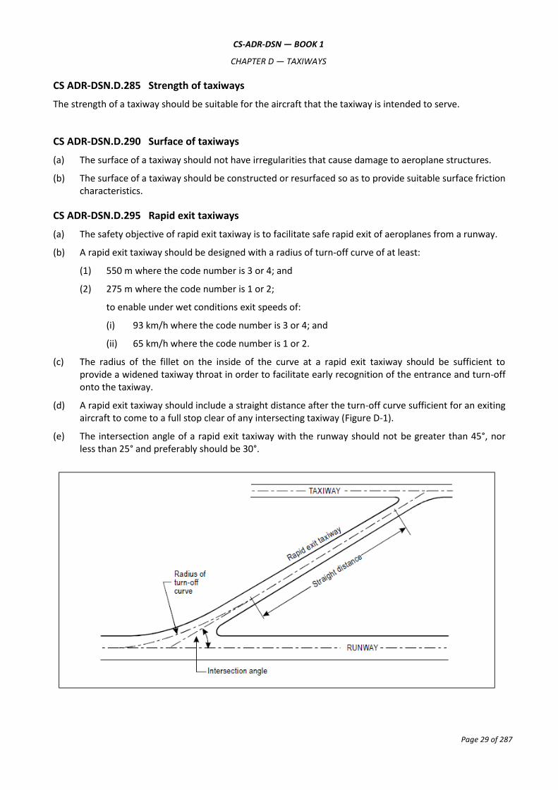
CS ADR-DSN.D.295 Rapid exit taxiways
(a) The safety objective of rapid exit taxiway is to facilitate safe rapid exit of aeroplanes from a runway.
(b) A rapid exit taxiway should be designed with a radius of turn-off curve of at least:
(1) 550 m where the code number is 3 or 4; and
(2) 275 m where the code number is 1 or 2;
to enable under wet conditions exit speeds of:
(i) 93 km/h where the code number is 3 or 4; and
(ii) 65 km/h where the code number is 1 or 2.
(c) The radius of the fillet on the inside of the curve at a rapid exit taxiway should be sufficient to provide a widened taxiway throat in order to facilitate early recognition of the entrance and turn-off onto the taxiway.
(d) A rapid exit taxiway should include a straight distance after the turn-off curve sufficient for an exiting aircraft to come to a full stop clear of any intersecting taxiway (Figure D-1).
(e) The intersection angle of a rapid exit taxiway with the runway should not be greater than 45°, nor less than 25° and preferably should be 30°.

CS-ADR-DSN — BOOK 1
CHAPTER D — TAXIWAYS
Page 30 of 287
Figure D-1. Rapid exit taxiway
CS ADR-DSN.D.300 Taxiways on bridges
(a) The width of that portion of a taxiway bridge capable of supporting aeroplanes, as measured perpendicularly to the taxiway centre line, should not be less than the width of the graded area of the strip provided for that taxiway unless a proven method of lateral restraint is provided which should not be hazardous for aeroplanes for which the taxiway is intended.
(b) Access should be provided to allow rescue and firefighting vehicles to intervene in both directions within the specified response time to the largest aeroplane for which the taxiway bridge is intended.
(c) A bridge should be constructed on a straight section of the taxiway with a straight section on both ends of the bridge to facilitate the alignment of aeroplanes approaching the bridge.
CS ADR-DSN.D.305 Taxiway shoulders
(a) Straight portions of a taxiway where the code letter is C, D, E, or F should be provided with shoulders which extend symmetrically on each side of the taxiway so that the overall width of the taxiway and its shoulders on straight portions is not less than:
(1) 60 m where the code letter is F;
(2) 44 m where the code letter is E;
(3) 38 m where the code letter is D; and
(4) 25 m where the code letter is C.
(b) On taxiway curves and on junctions or intersections where increased pavement is provided, the shoulder width should be not less than that on the adjacent straight portions of the taxiway.
(c) When a taxiway is intended to be used by turbine-engined aeroplanes, the surface of the taxiway shoulder should be prepared so as to resist erosion and the ingestion of the surface material by aeroplane engines.
CS ADR-DSN.D.310 Taxiway Strip
A taxiway, other than an aircraft stand taxilane, should be included in a strip.
CS ADR-DSN.D.315 Width of taxiway strips
(a) The safety objective of the width of taxiway strips is to allow safe use of taxiways in relation to adjacent objects.
(b) A taxiway strip should extend symmetrically on each side of the centre line of the taxiway throughout the length of the taxiway to at least the distance from the centre line given in Table D-1, column 11.
CS ADR-DSN.D.320 Objects on taxiway strips
The taxiway strip should provide an area clear of objects which may endanger taxiing aeroplanes.
CS ADR-DSN.D.325 Grading of taxiway strips
(a) The safety objective of the grading of a taxiway strip is to reduce the risk of damage to an aircraft accidentally running off the taxiway.

CS-ADR-DSN — BOOK 1
CHAPTER D — TAXIWAYS
Page 31 of 287
(b) The centre portion of a taxiway strip should provide a graded area to a distance from the centre line of the taxiway of at least:
(1) 11 m where the code letter is A;
(2) 12.5 m where the code letter is B or C;
(3) 19 m where the code letter is D;
(4) 22 m where the code letter is E; and
(5) 30 m where the code letter is F.
CS ADR-DSN.D.330 Slopes on taxiway strips
(a) The safety objective of limiting the longitudinal taxiway strip slopes and slope changes and of
minimum sight distances values is to reduce the probability of damage to an aircraft accidentally
running off the taxiway and to enable safe use of these areas by rescue and firefighting vehicles.
(b) The surface of the strip should be flush at the edge of the taxiway or shoulder if provided, and the graded portion should not have an upward transverse slope exceeding:
(1) 2.5 % for strips where the code letter is C, D, E, or F; and
(2) 3 % for strips of taxiways where the code letter is A or B;
the upward slope being measured with reference to the transverse slope of the adjacent taxiway surface and not the horizontal. The downward transverse slope should not exceed 5 % measured with reference to the horizontal.
(c) The transverse slopes on any portion of a taxiway strip beyond that to be graded should not exceed an upward or downward slope of 5 % as measured in the direction away from the taxiway.
CS ADR-DSN.D.335 Holding bays, runway-holding positions, intermediate holding positions, and road-holding positions
(a) Holding bay(s) or other bypasses of sufficient size and adequate construction should be provided where necessary, to make deviations in the departure sequence possible.
(b) A runway-holding position or positions should be established:
(1) on the taxiway, if the location or alignment of the taxiway is such that a taxiing aircraft or vehicle can infringe an obstacle limitation surface or interfere with the operation of radio navigation aids;
(2) on the taxiway, at the intersection of a taxiway and a runway; and
(3) at an intersection of a runway with another runway when the former runway is part of a standard taxi-route.
(c) An intermediate holding position should be established on a taxiway at any point other than a runway-holding position where it is desirable to define a specific holding limit.
(d) An emergency access road should be equipped with road-holding positions at all intersections with runways and taxiways.
(e) A road-holding position should be established at each intersection of a road with a runway.

CS-ADR-DSN — BOOK 1
CHAPTER D — TAXIWAYS
Page 32 of 287
CS ADR-DSN.D.340 Location of holding bays, runway-holding positions, intermediate holding positions, and road-holding positions
(a) The distance between a holding bay, runway-holding position established at a taxiway/runway intersection or road-holding position and the centre line of a runway should be in accordance with Table D-2 and such that a holding aircraft or vehicle should not interfere with the operation of radio navigation aids.
(b) At elevations greater than 700 m the distance of 90 m specified in Table D-2 for a precision approach runway code number 4 should be increased as follows:
(1) up to an elevation of 2 000 m; 1 m for every 100 m in excess of 700 m;
(2) elevation in excess of 2 000 m and up to 4 000 m; 13 m plus 1.5 m for every 100 m in excess of 2 000 m; and
(3) elevation in excess of 4 000 m and up to 5 000 m; 43 m plus 2 m for every 100 m in excess of 4 000 m.

CS-ADR-DSN — BOOK 1
CHAPTER D — TAXIWAYS
Page 33 of 287
Code numberd
Type of runway 1 2 3 4
Non-instrument 30 m 40 m 75 m 75 m
Non-precision approach 40 m 40 m 75 m 75 m
Precision approach category I 60 mb 60 mb 90 ma,b 90 ma,b,c
Precision approach categories II and III — — 90 ma,b 90 ma,b,c
Take-off runway 30 m 40 m 75 m 75 m
a. If a holding bay, runway-holding position, or road-holding position is at a lower elevation compared to the threshold, the distance may be decreased 5 m for every metre the bay or holding position is lower than the threshold, contingent upon not infringing the inner transitional surface.
b. This distance may need to be increased to avoid interference with radio navigation aids, particularly the glide path and localiser facilities (see CS ADR-DSN.D.340).
Note 1.— The distance of 90 m for code number 3 or 4 is based on an aircraft with a tail height of 20 m, a distance from the nose to the highest part of the tail of 52.7 m and a nose height of 10 m holding at an angle of 45° or more with respect to the runway centre line, being clear of the obstacle free zone and not accountable for the calculation of OCA/H.
Note 2.— The distance of 60 m for code number 2 is based on an aircraft with a tail height of 8 m, a distance from the nose to the highest part of the tail of 24.6 m and a nose height of 5.2 m holding at an angle of 45° or more with respect to the runway centre line, being clear of the obstacle free zone.
c. Where the code letter is F, this distance should be 107.5 m.
Note.— The distance of 107.5 m for code number 4 where the code letter is F is based on an aircraft with a tail height of 24 m, a distance from the nose to the highest part of the tail of 62.2 m and a nose height of 10 m holding at an angle of 45° or more with respect to the runway centre line, being clear of the obstacle free zone.
d. Elevation of taxiway should be taken into account for possible increase of the distances indicated in this table.
Table D-2 — Minimum distance from the runway centre line to a holding bay, runway-holding position, or road-holding position
CS-ADR-DSN — BOOK 1
CHAPTER E — APRONS
Page 34 of 287
CHAPTER E — APRONS
CS ADR-DSN.E.345 General
Aprons should be provided to permit the safe loading and off-loading of passengers, cargo, or mail as well as the servicing of aircraft without interfering with the aerodrome traffic.
CS ADR-DSN.E.350 Size of aprons
Intentionally blank
CS ADR-DSN.E.355 Strength of aprons
Each part of an apron should be capable of withstanding the traffic of the aircraft it is intended to serve, due consideration being given to the fact that some portions of the apron should be subjected to a higher density of traffic and, as a result of slow moving or stationary aircraft, to higher stresses than a runway.
CS ADR-DSN.E.360 Slopes on aprons
(a) Slopes on an apron should be sufficient to prevent accumulation of water on the surface of the apron but should be kept to the minimum required to facilitate effective drainage.
(b) On an aircraft stand the maximum slope should not exceed 1 % in any direction.
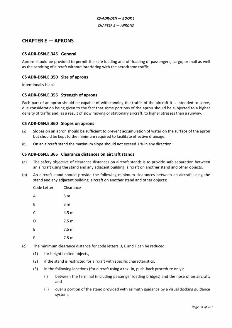
CS ADR-DSN.E.365 Clearance distances on aircraft stands
(a) The safety objective of clearance distances on aircraft stands is to provide safe separation between an aircraft using the stand and any adjacent building, aircraft on another stand and other objects.
(b) An aircraft stand should provide the following minimum clearances between an aircraft using the stand and any adjacent building, aircraft on another stand and other objects:
Code Letter Clearance
A 3 m
B 3 m
C 4.5 m
D 7.5 m
E 7.5 m
F 7.5 m
(c) The minimum clearance distance for code letters D, E and F can be reduced:
(1) for height limited objects,
(2) if the stand is restricted for aircraft with specific characteristics,
(3) in the following locations (for aircraft using a taxi-in, push-back procedure only):
(i) between the terminal (including passenger loading bridges) and the nose of an aircraft; and
(ii) over a portion of the stand provided with azimuth guidance by a visual docking guidance system.

CS-ADR-DSN — BOOK 1
CHAPTER F — ISOLATED AIRCRAFT PARKING POSITION
Page 35 of 287
CHAPTER F — ISOLATED AIRCRAFT PARKING POSITION
CS ADR-DSN.F.370 Isolated aircraft parking position
(a) The safety objective of the isolated aircraft parking position is to provide safe separation between aircraft that need isolation and other aerodrome activities.
(b) General
An isolated aircraft parking position should be designated by the aerodrome operator for parking of aircraft that needs isolation from normal aerodrome activities.
(c) Location
The isolated aircraft parking position should be located at the maximum distance practicable and in any case never less than 100 m from other parking positions, buildings, or public areas, etc.

CS-ADR-DSN — BOOK 1
CHAPTER G — DE-ICING/ANTI-ICING FACILITIES
Page 36 of 287
CHAPTER G — DE-ICING/ANTI-ICING FACILITIES
CS ADR-DSN.G.375 General
Aeroplane de-icing/anti-icing facilities should be provided at an aerodrome where icing conditions are expected to occur.
CS ADR-DSN.G.380 Location
(a) De-icing/anti-icing facilities should be provided either at aircraft stands or at specified remote areas.
(b) The de-icing/anti-icing facilities should be located to be clear of the obstacle limitation surfaces to not cause interference to the radio navigation aids and be clearly visible from the air traffic control tower for clearing the treated aeroplane.
CS ADR-DSN.G.385 Size of de-icing/anti-icing pads
(a) The safety objective of the de-icing/anti-icing pad dimensions is to allow safe positioning of aircraft for de-icing/anti-icing, including sufficient room for the safe movement of de-icing vehicles around the aircraft.
(b) The size of a de-icing/anti-icing pad should be equal to the parking area required by the most demanding aircraft in a given category with at least 3.8 m clear paved area all around the aeroplane for the movement of the de-icing/anti-icing vehicles.
CS ADR-DSN.G.390 Slopes on de-icing/anti-icing pads
The de-icing/anti-icing pads should be provided with suitable slopes:
(a) to ensure satisfactory drainage of the area;
(b) to permit collection of all excess de-icing/anti-icing fluid running off an aeroplane; and
(c) not to hinder the movement of aircraft on or off the pad.
CS ADR-DSN.G.395 Strength of de-icing/anti-icing pads
The de-icing/anti-icing pad should be capable of withstanding the traffic of the aircraft it is intended to serve.
CS ADR-DSN.G.400 Clearance distances on a de-icing/anti-icing pad
(a) The safety objective of the clearance distances on a de-icing/anti-icing pad is to provide safe separation between an aircraft using the stand and any adjacent building, aircraft on another stand and other objects.
(b) A de-icing/anti-icing pad should provide the following minimum clearances between an aircraft using the stand and any adjacent building, aircraft on another stand and other objects:
Code Letter Clearance
A 3.8 m
B 3.8 m
C 4.5 m
D 7.5 m

CS-ADR-DSN — BOOK 1
CHAPTER G — DE-ICING/ANTI-ICING FACILITIES
Page 37 of 287
E 7.5 m
F 7.5 m
(c) If the pad layout is such as to include bypass configuration, the minimum separation distances specified in Table D-1, column (13) should be provided.
(d) Where the de-icing/anti-icing facility is located adjoining a regular taxiway, the taxiway minimum separation distance specified in Table D-1, column (11) should be provided (see Figure G-1).
Figure G-1. Minimum separation distance on a de-icing/anti-icing facility
Minimum separation distance
(see CS-ADR.DSN.G.400 (d)
and Table D-1, column 11)

CS-ADR-DSN — BOOK 1
CHAPTER H — OBSTACLE LIMITATION SURFACES
Page 38 of 287
CHAPTER H — OBSTACLE LIMITATION SURFACES
CS ADR-DSN.H.405 Applicability
Applicability: The purpose of the obstacle limitation surfaces is to define the airspace around aerodromes to be maintained free from obstacles so as to permit the intended aeroplane operations at the aerodromes to be conducted safely.
CS ADR-DSN.H.410 Outer horizontal surface
Intentionally blank
CS ADR-DSN.H.415 Conical surface
(a) Applicability: The purpose of the conical surface is to facilitate safe visual manoeuvring in the vicinity of the aerodrome.
(b) Description: A surface sloping upwards and outwards from the periphery of the inner horizontal surface.
(c) Characteristics: The limits of the conical surface should comprise:
(1) a lower edge coincident with the periphery of the inner horizontal surface; and
(2) an upper edge located at a specified height above the inner horizontal surface.
(d) The slope of the conical surface should be measured in a vertical plane perpendicular to the
periphery of the inner horizontal surface.
CS ADR-DSN.H.420 Inner horizontal surface
(a) Applicability: The purpose of the inner horizontal surface is to protect airspace for visual manoeuvring prior to landing.
(b) Description: A surface located in a horizontal plane above an aerodrome and its environs.
(c) Characteristics: The outer limits of the inner horizontal surface are defined by circular arcs centred on the geometric centre of the runway, on the intersection of the extended RWY centre line with the end of the RWY strip joined tangentially by straight lines or points established for such purpose as in Figure H-1.
(d) The height of the inner horizontal surface should be measured above an established elevation datum. The elevation datum used for the height of the inner horizontal surface should be:
(1) the elevation of the highest point of the lowest threshold of the related runway; or
(2) the elevation of the highest point of the highest threshold of the related runway; or
(3) the elevation of the highest point of the runway; or
(4) the aerodrome elevation.
CS ADR-DSN.H.425 Approach surface
(a) Applicability: The purpose of the approach surface is to protect an aircraft during the final approach to the runway by defining the area that should be kept free from obstacles to protect an aeroplane in the final phase of the approach-to-land manoeuvre.
CS-ADR-DSN — BOOK 1
CHAPTER H — OBSTACLE LIMITATION SURFACES
Page 39 of 287
(b) Description: An inclined plane or combination of planes preceding the threshold.
(c) Characteristics. The limits of the approach surface should comprise:
(1) an inner edge of specified length, horizontal and perpendicular to the extended centre line of the runway, and located at a specified distance before the threshold;
(2) two sides originating at the ends of the inner edge and diverging uniformly at a specified rate from the extended centre line of the runway; and
(3) an outer edge parallel to the inner edge.
The above surfaces should be varied when lateral offset, offset or curved approaches are utilised, specifically, two sides originating at the ends of the inner edge and diverging uniformly at a specified rate from the extended centre line of the lateral offset, offset or curved ground track.
(d) The elevation of the inner edge should be equal to the elevation of the mid-point of the threshold.
(e) The slope(s) of the approach surface should be measured in the vertical plane containing the centre line of the runway and should continue containing the centre line of any lateral offset or curved ground track.
CS ADR-DSN.H.430 Transitional surface
(a) Applicability: The purpose of the transitional surface is to define the limit of the area available for buildings, other structures or natural obstructions, such as trees.
(b) Description: A complex surface along the side of the strip and part of the side of the approach surface that slopes upwards and outwards to the inner horizontal surface.
(c) Characteristics: The limits of a transitional surface should comprise:
(1) a lower edge beginning at the intersection of the side of the approach surface with the inner horizontal surface and extending down the side of the approach surface to the inner edge of the approach surface and from there along the length of the strip parallel to the runway centre line; and
(2) an upper edge located in the plane of the inner horizontal surface.
(d) The elevation of a point on the lower edge should be:
(1) along the side of the approach surface — equal to the elevation of the approach surface at that point; and
(2) along the strip — equal to the elevation of the nearest point on the centre line of the runway or its extension.
(e) The slope of the transitional surface should be measured in a vertical plane at right angles to the centre line of the runway.

CS-ADR-DSN — BOOK 1
CHAPTER H — OBSTACLE LIMITATION SURFACES
Page 40 of 287
Figure H-1. Inner horizontal surface where the runway is code 4

CS-ADR-DSN — BOOK 1
CHAPTER H — OBSTACLE LIMITATION SURFACES
Page 41 of 287
Figure H-2. Obstacle limitation surfaces
See Figure H-3. for inner approach, inner transitional, and balked landing obstacle
limitation surfaces
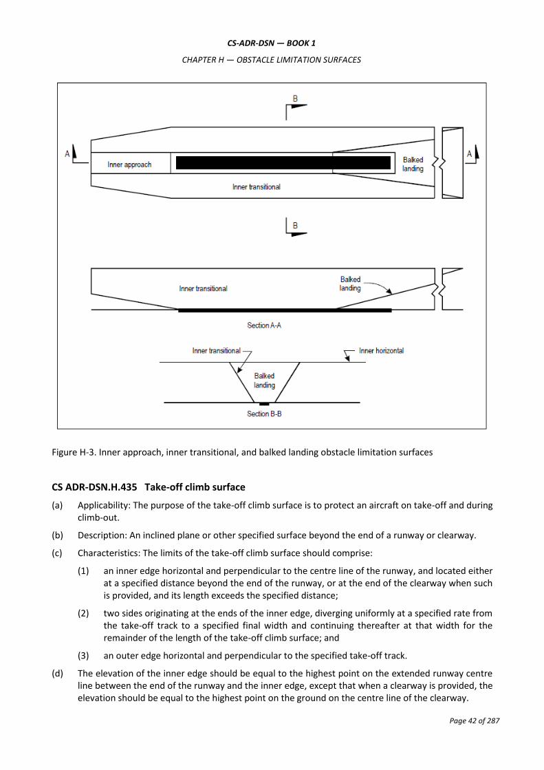
CS-ADR-DSN — BOOK 1
CHAPTER H — OBSTACLE LIMITATION SURFACES
Page 42 of 287
Figure H-3. Inner approach, inner transitional, and balked landing obstacle limitation surfaces
CS ADR-DSN.H.435 Take-off climb surface
(a) Applicability: The purpose of the take-off climb surface is to protect an aircraft on take-off and during climb-out.
(b) Description: An inclined plane or other specified surface beyond the end of a runway or clearway.
(c) Characteristics: The limits of the take-off climb surface should comprise:
(1) an inner edge horizontal and perpendicular to the centre line of the runway, and located either at a specified distance beyond the end of the runway, or at the end of the clearway when such is provided, and its length exceeds the specified distance;
(2) two sides originating at the ends of the inner edge, diverging uniformly at a specified rate from the take-off track to a specified final width and continuing thereafter at that width for the remainder of the length of the take-off climb surface; and
(3) an outer edge horizontal and perpendicular to the specified take-off track.
(d) The elevation of the inner edge should be equal to the highest point on the extended runway centre line between the end of the runway and the inner edge, except that when a clearway is provided, the elevation should be equal to the highest point on the ground on the centre line of the clearway.

CS-ADR-DSN — BOOK 1
CHAPTER H — OBSTACLE LIMITATION SURFACES
Page 43 of 287
(e) In the case of a straight take-off flight path, the slope of the take-off climb surface should be measured in the vertical plane containing the centre line of the runway.
(f) In the case of a take-off flight path involving a turn, the take-off climb surface should be a complex surface containing the horizontal normals to its centre line, and the slope of the centre line should be the same as that for a straight take-off flight path.
CS ADR-DSN.H.440 Slewed take-off climb surface
Intentionally blank
CS ADR-DSN.H.445 Obstacle Free Zone (OFZ)
(a) An OFZ is intended to protect aeroplanes from fixed and mobile obstacles during Category I, II, or III operations when approaches are continued below decision height, and during any subsequent missed approach or balked landing with all engines operating normally. It is not intended to supplant the requirement of other surfaces or areas where these are more demanding.
(b) The OFZ is made up of the following obstacle limitation surfaces:
(1) inner approach surface;
(2) inner transitional surfaces; and
(3) balked landing surface.
CS ADR-DSN.H.450 Inner approach surface
(a) Applicability: The purpose of the inner approach surface is to protect final precision approaches.
(b) Description: A rectangular portion of the approach surface immediately preceding the threshold.
(c) Characteristics: The limits of the inner approach surface should comprise:
(1) an inner edge coincident with the location of the inner edge of the approach surface but of its own specified length;
(2) two sides originating at the ends of the inner edge and extending parallel to the vertical plane containing the centre line of the runway; and
(3) an outer edge parallel to the inner edge.
CS ADR-DSN.H.455 Inner transitional surface
(a) Applicability: The purpose of the inner transitional surface is to protect aeroplanes during precision approaches and balked landing.
(b) Description: A surface similar to the transitional surface but closer to the runway.
(c) Characteristics: The limits of an inner transitional surface should comprise:
(1) a lower edge beginning at the end of the inner approach surface and extending down the side of the inner approach surface to the inner edge of that surface, from there along the strip parallel to the runway centre line to the inner edge of the balked landing surface, and from there up the side of the balked landing surface to the point where the side intersects the inner horizontal surface; and
(2) an upper edge located in the plane of the inner horizontal surface.
(d) The elevation of a point on the lower edge should be:
CS-ADR-DSN — BOOK 1
CHAPTER H — OBSTACLE LIMITATION SURFACES
Page 44 of 287
(1) along the side of the inner approach surface and balked landing surface — equal to the elevation of the particular surface at that point; and
(2) along the strip — equal to the elevation of the nearest point on the centre line of the runway or its extension.
(e) The slope of the inner transitional surface should be measured in a vertical plane at right angles to the centre line of the runway.
CS ADR-DSN.H.460 Balked landing surface
(a) Applicability: The purpose of the balked landing surface is to protect balked landing.
(b) Description: An inclined plane located at a specified distance after the threshold, extending between the inner transitional surfaces.
(c) Characteristics: The limits of the balked landing surface should comprise:
(1) an inner edge horizontal and perpendicular to the centre line of the runway and located at a specified distance after the threshold;
(2) two sides originating at the ends of the inner edge and diverging uniformly at a specified rate from the vertical plane containing the centre line of the runway; and
(3) an outer edge parallel to the inner edge and located in the plane of the inner horizontal surface.
(d) The elevation of the inner edge should be equal to the elevation of the runway centre line at the location of the inner edge.
(e) The slope of the balked landing surface should be measured in the vertical plane containing the centre line of the runway.
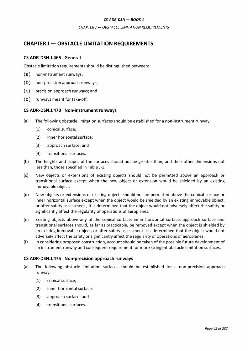
CS-ADR-DSN — BOOK 1
CHAPTER J — OBSTACLE LIMITATION REQUIREMENTS
Page 45 of 287
CHAPTER J — OBSTACLE LIMITATION REQUIREMENTS
CS ADR-DSN.J.465 General
Obstacle limitation requirements should be distinguished between:
(a) non-instrument runways;
(b) non-precision approach runways;
(c) precision approach runways; and
(d) runways meant for take-off.
CS ADR-DSN.J.470 Non-instrument runways
(a) The following obstacle limitation surfaces should be established for a non-instrument runway:
(1) conical surface;
(2) inner horizontal surface;
(3) approach surface; and
(4) transitional surfaces.
(b) The heights and slopes of the surfaces should not be greater than, and their other dimensions not less than, those specified in Table J-1.
(c) New objects or extensions of existing objects should not be permitted above an approach or transitional surface except when the new object or extension would be shielded by an existing immovable object.
(d) New objects or extensions of existing objects should not be permitted above the conical surface or inner horizontal surface except when the object would be shielded by an existing immovable object, or after safety assessment , it is determined that the object would not adversely affect the safety or significantly affect the regularity of operations of aeroplanes.
(e) Existing objects above any of the conical surface, inner horizontal surface, approach surface and transitional surfaces should, as far as practicable, be removed except when the object is shielded by an existing immovable object, or after safety assessment it is determined that the object would not adversely affect the safety or significantly affect the regularity of operations of aeroplanes.
(f) In considering proposed construction, account should be taken of the possible future development of an instrument runway and consequent requirement for more stringent obstacle limitation surfaces.
CS ADR-DSN.J.475 Non-precision approach runways
(a) The following obstacle limitation surfaces should be established for a non-precision approach runway:
(1) conical surface;
(2) inner horizontal surface;
(3) approach surface; and
(4) transitional surfaces.

CS-ADR-DSN — BOOK 1
CHAPTER J — OBSTACLE LIMITATION REQUIREMENTS
Page 46 of 287
(b) The heights and slopes of the surfaces should not be greater than, and their other dimensions not less than, those specified in Table J-1, except in the case of the horizontal section of the approach surface (see paragraph (c) below).
(c) The approach surface should be horizontal beyond the point at which the 2.5 % slope intersects:
(1) a horizontal plane 150 m above the threshold elevation; or
(2) the horizontal plane passing through the top of any object that governs the obstacle clearance altitude/height (OCA/H);
whichever is the higher.
(d) New objects or extensions of existing objects should not be permitted above an approach surface within 3 000 m of the inner edge or above a transitional surface except when the new object or extension would be shielded by an existing immovable object.
(e) New objects or extensions of existing objects should not be permitted above the approach surface beyond 3 000 m from the inner edge, the conical surface or inner horizontal surface except when the object would be shielded by an existing immovable object, or after an safety assessment , it is determined that the object would not adversely affect the safety or significantly affect the regularity of operations of aeroplanes.
(f) Existing objects above any of the surfaces required by paragraph (a) should as far as practicable be removed except when the object would be shielded by an existing immovable object, or after safety assessment , it is determined that the object would not adversely affect the safety or significantly affect the regularity of operations of aeroplanes.
CS ADR-DSN.J.480 Precision approach runways
(a) The following obstacle limitation surfaces should be established for a precision approach runway category I:
(1) conical surface;
(2) inner horizontal surface;
(3) approach surface; and
(4) transitional surfaces.
(b) The following obstacle limitation surfaces should be established for a precision approach runway category II or III:
(1) conical surface;
(2) inner horizontal surface;
(3) approach surface and inner approach surface;
(4) transitional surfaces and inner transitional surfaces; and
(5) balked landing surface.
(c) The heights and slopes of the surfaces should not be greater than, and their other dimensions not less than, those specified in Table J-1, except in the case of the horizontal section of the approach surface in paragraph (d) below.
(d) The approach surface should be horizontal beyond the point at which the 2.5 % slope intersects:
(1) a horizontal plane 150 m above the threshold elevation; or

CS-ADR-DSN — BOOK 1
CHAPTER J — OBSTACLE LIMITATION REQUIREMENTS
Page 47 of 287
(2) the horizontal plane passing through the top of any object that governs the obstacle clearance limit;
whichever is the higher.
(e) Fixed objects should not be permitted above the inner approach surface, the inner transitional surface or the balked landing surface, except for frangible objects which because of their function should be located on the strip. Mobile objects should not be permitted above these surfaces during the use of the runway for landing.
(f) New objects or extensions of existing objects should not be permitted above an approach surface or a transitional surface except when the new object or extension would be shielded by an existing immovable object.
(g) New objects or extensions of existing objects should not be permitted above the conical surface and the inner horizontal surface except when an object would be shielded by an existing immovable object, or after safety assessment , it is determined that the object would not adversely affect the safety or significantly affect the regularity of operations of aeroplanes.
(h) Existing objects above an approach surface, a transitional surface, the conical surface and inner horizontal surface should, as far as practicable, be removed except when an object would be shielded by an existing immovable object, or after safety assessment , it is determined that the object would not adversely affect the safety or significantly affect the regularity of operations of aeroplanes.
CS ADR-DSN.J.485 Runways meant for take-off
(a) The safety objective of the take-off climb surface slopes and dimensions is to allow safe take-off operations by defining the limits above which new obstacles should not be permitted unless shielded by an existing immoveable object.
(b) A take-off climb surface should be established for a runway meant for take-off.
(c) The dimensions of the surface should be not less than the dimensions specified in Table J-2, except that a lesser length may be adopted for the take-off climb surface where such lesser length would be consistent with procedural measures adopted to govern the outward flight of aeroplanes.
(d) New objects or extensions of existing objects should not be permitted above a take-off climb surface except when the new object or extension would be shielded by an existing immovable object.
(e) Existing objects that extend above a take-off climb surface should as far as practicable be removed except when an object is shielded by an existing immovable object, or after safety assessment it is determined that the object would not adversely affect the safety or significantly affect the regularity of operations of aeroplanes.
CS ADR-DSN.J.490 Other objects
(a) Objects which do not project through the approach surface but which would nevertheless adversely
affect the optimum siting or performance of visual or non-visual aids should, as far as practicable, be
removed.
(b) Anything which may, after safety assessment , endanger aeroplanes on the movement area or in the air within the limits of the inner horizontal and conical surfaces should be regarded as an obstacle and should be removed in so far as practicable.

CS-ADR-DSN — BOOK 1
CHAPTER J — OBSTACLE LIMITATION REQUIREMENTS
Page 48 of 287
APPROACH RUNWAYS
RUNWAY CLASSIFICATION
Non-instrument Code number
Non-precision approach Code number
Precision approach category
I
Code number
II or III Code
number
Surface and dimensions
a
1 2 3 4 1, 2 3 4 1, 2 3, 4 3, 4
(1) (2) (3) (4) (5) (6) (7) (8) (9) (10) (11)
CONICAL
Slope 5 % 5 % 5 % 5 % 5 % 5 % 5 % 5 % 5 % 5 %
Height 35 m 55 m 75 m 100 m 60 m 75 m 100 m 60 m 100 m 100 m
INNER HORIZONTAL
Height 45 m 45 m 45 m 45 m 45 m 45 m 45 m 45 m 45 m 45 m
Radius 2 000 m 2 500 m 4 000 m 4 000 m 3 500 m 4 000 m 4 000 m 3 500 m 4 000 m 4 000 m
INNER APPROACH
Width - - - - - - - 90 m 120 me 120 m
e
Distance from threshold
- - - - - - - 60 m 60 m 60 m
Length - - - - - - - 900 m 900 m 900 m
Slope - - - - - - - 2.5 % 2 % 2 %
APPROACH
Length of inner edge
60 m 80 m 150 m 150 m 150 m 300 m 300 m 150 m 300 m 300 m
Distance from threshold
30 m 60 m 60 m 60 m 60 m 60 m 60 m 60 m 60 m 60 m
Divergence (each side
10 % 10 % 10 % 10 % 15 % 15 % 15 % 15 % 15 % 15 %
First section
Length 1 600 m 2 500 m 3 000 m 3 000 m 2 500 m 3 000 m 3 000 m 3 000 m 3 000 m 3 000 m
Slope 5 % 4 % 3.33 % 2.5 % 3.33 % 2 % 2 % 2.5 % 2 % 2 %

CS-ADR-DSN — BOOK 1
CHAPTER J — OBSTACLE LIMITATION REQUIREMENTS
Page 49 of 287
Second section
Length - - - - - 3 600 mb 3 600 m
b 12 000 m 3 600 m
b 3 600 m
b
Slope - - - - - 2.5 % 2.5 % 3 % 2.5 % 2.5 %
Horizontal section
Length - - - - - 8 400 mb 8 400 m
b - 8 400 m
b 8 400 m
b
Total length - - - - - 15 000 m 15 000 m 15 000 m 15 000 m 15 000 m
TRANSITIONAL
Slope 20 % 20 % 14.3 % 14.3 % 20 % 14.3 % 14.3 % 14.3 % 14.3 % 14.3 %
INNER TRANSITIONAL
Slope - - - - - - - 40 % 33.3 % 33.3 %
BALKED LANDING SURFACE
Length of inner edge
- - - - - - - 90 m 120 me 120 m
e
Distance from threshold
- - - - - - - c 1 800 md 1 800 m
d
Divergence (each side)
- - - - - - - 10 % 10 % 10 %
Slope - - - - - - - 4 % 3.33 % 3.33 %
a. All dimensions are measured horizontally unless specified otherwise. b. Variable length (CS ADR-DSN.J.475 (c) or CS ADR-DSN.J.480 (d)). c. Distance to the end of strip. d. Or end of runway whichever is less.
e. Where the code letter is F (Column (3) of Table A-1), the width is increased to 155 m.
Table J-1. Dimensions and slopes of obstacle limitation surfaces — Approach runways

CS-ADR-DSN — BOOK 1
CHAPTER J — OBSTACLE LIMITATION REQUIREMENTS
Page 50 of 287
RUNWAYS MEANT FOR TAKE-OFF
Code number
Surface and dimensionsa 1 2 3 or 4
(1) (2) (3) (4)
TAKE-OFF CLIMB
Length of inner edge 60e m 80e m 180 m
Distance from runway endb 30 m 60 m 60 m
Divergence (each side) 10 % 10 % 12.5 %
Final width 380 m 580 m 1 200 m 1 800 mc
Length 1 600 m 2 500 m 15 000 m
Slope 5 % 4 % 2 %d
a. All dimensions are measured horizontally unless specified otherwise. b. The take-off climb surface starts at the end of the clearway if the clearway length exceeds the
specified distance. c. 1 800 m when the intended track includes changes of heading greater than 15° for operations
conducted in IMC, VMC by night. d. See CS ADR-DSN.J.485 (c) and (e). e. Where clearway is provided the length of the inner edge should be 150 m.
Table J-2 Dimensions and slopes of obstacle limitation surfaces — Runways meant for take-off

CS-ADR-DSN — BOOK 1
CHAPTER K — VISUAL AIDS FOR NAVIGATION (INDICATORS AND SIGNALLING DEVICES)
Page 51 of 287
CHAPTER K — VISUAL AIDS FOR NAVIGATION (INDICATORS AND SIGNALLING DEVICES)
CS ADR-DSN.K.490 Wind direction indicator
(a) An aerodrome should be equipped with a sufficient number of wind direction indicators in order to provide wind information to the pilot during approach and take-off.
(b) Location:
Each wind direction indicator should be located so that at least one wind direction indicator is visible from aircraft in flight, during approach or on the movement area before take-off, and in such a way as to be free from the effects of air disturbances caused by nearby objects.
(c) Characteristics:
(1) Each wind direction indicator should be in the form of a truncated cone made of fabric and should have a length of not less than 3.6 m and a diameter, at the larger end, of not less than 0.9 m.
(2) It should be constructed so that it gives a clear indication of the direction of the surface wind and a general indication of the wind speed.
(3) The colour or colours should be so selected as to make the wind direction indicator clearly visible and understandable from a height of at least 300 m. Having regard to background:
(i) where practicable, a single colour should be used; and
(ii) where a combination of two colours is required to give adequate conspicuity against changing backgrounds, they should preferably be orange and white, red and white, or black and white, and should be arranged in five alternate bands, the first and last bands being the darker colour.
(d) Night conditions:
Provision should be made for illuminating a sufficient number of wind indicators at an aerodrome intended for use at night.
CS ADR-DSN.K.495 Landing direction indicator
(a) Location: Where provided, a landing direction indicator should be located in a conspicuous place on the aerodrome.
(b) Characteristics:
(1) The landing direction indicator should be in the form of a ‘T’.
(2) The shape and minimum dimensions of a landing ‘T’ should be as shown in Figure K-1.
(3) The colour of the landing ‘T’ should be either white or orange, the choice being dependent on the colour that contrasts best with the background against which the indicator should be viewed.
(4) Where used at night, the landing ‘T’ should either be illuminated or outlined by white lights.

CS-ADR-DSN — BOOK 1
CHAPTER K — VISUAL AIDS FOR NAVIGATION (INDICATORS AND SIGNALLING DEVICES)
Page 52 of 287
Figure K-1. Landing direction indicator
CS ADR-DSN.K.500 Signalling lamp
(a) A signalling lamp should be provided at a controlled aerodrome in the aerodrome control tower.
(b) Characteristics:
(1) A signalling lamp should be capable of producing red, green and white signals, and of:
(i) being aimed manually at any target as required; and
(ii) giving a signal in any one colour followed by a signal in either of the two other colours.
(2) The beam spread should be not less than 1° or greater than 3°, with negligible light beyond 3°. When the signalling lamp is intended for use in the daytime, the intensity of the coloured light should be not less than 6 000 cd.
CS ADR-DSN.K.505 Signal panels and signal area
Intentionally blank
CS ADR-DSN.K.510 Location of signal panels and signal area
Intentionally blank
CS ADR-DSN.K.515 Characteristics of signal panels and signal area
Intentionally blank

CS-ADR-DSN — BOOK 1
CHAPTER L — VISUAL AIDS FOR NAVIGATION (MARKINGS)
Page 53 of 287
CHAPTER L — VISUAL AIDS FOR NAVIGATION (MARKINGS)
CS ADR-DSN.L.520 General — Colour and conspicuity
Markings should be of a conspicuous colour and contrast with the surface on which they are laid.
(a) Runway markings should be white.
(b) Markings for taxiways, runway turn pads, and aircraft stands should be yellow.
(c) Apron safety lines should be of a conspicuous colour which should contrast with that used for aircraft stand markings.
(d) When it is operationally necessary to apply temporary runway or taxiway markings, those markings should comply with the relevant CS.
CS ADR-DSN.L.525 Runway designation marking
(a) Applicability: A runway designation marking should be provided at the thresholds of a runway.
(b) Location and positioning: A runway designation marking should be located at a threshold as shown in Figure L-1 as appropriate.
(c) Characteristics:
(1) A runway designation marking should consist of a two-digit number and on parallel runways should be supplemented with a letter.
(i) On a single runway, dual parallel runways and triple parallel runways, the two-digit number should be the whole number nearest the one-tenth of the magnetic North when viewed from the direction of approach.
(ii) On four or more parallel runways, one set of adjacent runways should be numbered to the nearest one-tenth magnetic azimuth and the other set of adjacent runways numbered to the next nearest one-tenth of the magnetic azimuth.
(iii) When a runway designation marking consists of a single digit number, it should be preceded by a zero.
(2) In the case of parallel runways, each runway designation number should be supplemented by a letter as follows, in the order shown from left to right when viewed from the direction of approach:
(i) for two parallel runways: ‘L’ ‘R’;
(ii) for three parallel runways: ‘L’ ‘C’ ‘R’;
(iii) for four parallel runways: ‘L’ ‘R’ ‘L’ ‘R’;
(iv) for five parallel runways: ‘L’ ‘C’ ‘R’ ‘L’ R’ or
‘L’ ‘R’ ‘L’ ‘C’ ‘R’; and
(v) for six parallel runways: ‘L’ ‘C’ ‘R’ ‘L’ ‘C’ ‘R’.
(3) The numbers and letters should be in the form and proportion shown in Figure L-2. The dimensions should be not less than those shown in Figure L-2. Where the numbers are incorporated in the threshold marking, larger dimensions should be used in order to fill adequately the gap between the stripes of the threshold marking.

CS-ADR-DSN — BOOK 1
CHAPTER L — VISUAL AIDS FOR NAVIGATION (MARKINGS)
Page 54 of 287
Figure L-1 Runway designation, centre line and threshold markings

CS-ADR-DSN — BOOK 1
CHAPTER L — VISUAL AIDS FOR NAVIGATION (MARKINGS)
Page 55 of 287
Figure L-2. Form and proportions of numbers and letters for runway designation markings

CS-ADR-DSN — BOOK 1
CHAPTER L — VISUAL AIDS FOR NAVIGATION (MARKINGS)
Page 56 of 287
CS ADR-DSN.L.530 Runway centre line marking
(a) Applicability: A runway centre line marking should be provided on a paved runway.
(b) Location: A runway centre line marking should be located along the centre line of the runway between the runway designation marking as shown in Figure L-1, except when interrupted as given in CS ADR-DSN.L.560.
(c) Characteristics:
(1) A runway centre line marking should consist of a line of uniformly spaced stripes and gaps. The length of a stripe plus a gap should be not less than 50 m or more than 75 m. The length of each stripe should be at least equal to the length of the gap or 30 m, whichever is greater.
(2) The width of the stripes should be not less than:
(i) 0.90 m on precision approach category II and III runways;
(ii) 0.45 m on non-precision approach runways where the code number is 3 or 4, and precision approach category I runways; and
(iii) 0.30 m on non-precision approach runways where the code number is 1 or 2, and on non-instrument runways.
CS ADR-DSN.L.535 Threshold marking
(a) Applicability and location: A threshold marking should be provided at the threshold of a runway.
(b) Characteristics:
(1) The stripes of the threshold marking should commence 6 m from the threshold.
(2) A runway threshold marking should consist of a pattern of longitudinal stripes of uniform dimensions disposed symmetrically about the centre line of a runway as shown in Figure L-1(A) and L-1(B) for a runway width of 45 m. The number of stripes should be in accordance with the runway width as follows:
Runway width Number of stripes
18 m 4
23 m 6
30 m 8
45 m 12
60 m 16
except that on non-precision approach and non-instrument runways 45 m or greater in width, they may be as shown in Figure L-1(C).
(3) The stripes should extend laterally to within 3 m of the edge of a runway or to a distance of 27 m on either side of a runway centre line, whichever results in the smaller lateral distance.
(4) Where a runway designation marking is placed within a threshold marking, there should be a minimum of three stripes on each side of the centre line of the runway.
(5) Where a runway designation marking is placed above a threshold marking, the stripes should be continued across the runway. The stripes should be at least 30 m long and approximately 1.80 m wide with spacings of approximately 1.80 m between them. Where the stripes are continued across a runway, a double spacing should be used to separate the two stripes

CS-ADR-DSN — BOOK 1
CHAPTER L — VISUAL AIDS FOR NAVIGATION (MARKINGS)
Page 57 of 287
nearest the centre line of the runway, and in the case where the designation marking is included within the threshold marking, this spacing should be 22.5 m.
(c) Displaced threshold:
(1) Where a threshold is displaced from the extremity of a runway or where the extremity of a runway is not square with the runway centre line, a transverse stripe as shown in Figure L-3(B) should be added to the threshold marking.
(2) A transverse stripe should be not less than 1.80 m wide.
(3) Where a runway threshold is permanently displaced, arrows conforming to Figure L-3(B) should be provided on the portion of the runway before the displaced threshold.
(4) When a runway threshold is temporarily displaced from the normal position, it should be marked as shown in Figure L-3(A) or L-3(B), and all markings prior to the displaced threshold should be obscured except the runway centre line marking which should be converted to arrows.
Figure L-3. Displaced threshold markings
CS ADR-DSN.L.540 Aiming point marking
(a) Applicability:
(1) An aiming point marking should be provided at each approach end of an instrument runway where the code number is 2, 3, or 4.

CS-ADR-DSN — BOOK 1
CHAPTER L — VISUAL AIDS FOR NAVIGATION (MARKINGS)
Page 58 of 287
(2) An aiming point marking should be provided when additional conspicuity of the aiming point is required at each approach end of:
(i) a non-instrument runway where the code number is 3 or 4,
(ii) an instrument runway where the code number is 1.
(b) Characteristics. The aiming point marking should commence no closer to the threshold than the distance indicated in the appropriate column of Table L-1, except that, on a runway equipped with a PAPI system, the beginning of the marking should be coincident with the visual approach slope origin.
Landing distance available
Location and dimensions
Less than 800 m 800 m up to but not
including 1 200 m
1 200 m up to but not including 2 400
m 2 400 m and above
(1) (2) (3) (4) (5)
Distance from threshold to beginning of markinga
150 m 250 m 300 m 400 m
Length of stripeb
30-45 m 30-45 m 45-60 m 45-60 m
Width of stripe 4 m 6 m 6-10 mc 6-10 mc
Lateral spacing between inner sides of stripes
6 md 9 md 18-22.5 m 18-22.5 m
a Where a PAPI system is provided for the runway, the beginning of the marking should be coincident with the visual approach slope origin.
b Where greater dimensions of the specified ranges are intended to be used where increased conspicuity is required.
c Where lateral spacing may be varied within these limits to minimise the contamination of the marking by rubber deposits.
d These figures were deduced by reference to the outer main gear wheel span which is element 2 of the aerodrome reference code
Table L-1. Location and dimensions of aiming point marking (c) An aiming point marking should consist of two conspicuous stripes. The dimensions of the stripes and
the lateral spacing between their inner sides should be in accordance with the provisions of the appropriate column of Table L-1.
CS ADR-DSN.L.545 Touchdown zone marking
(a) Applicability:
(1) A touchdown zone marking should be provided in the touchdown zone of a paved precision approach runway where the code number is 2, 3, or 4.

CS-ADR-DSN — BOOK 1
CHAPTER L — VISUAL AIDS FOR NAVIGATION (MARKINGS)
Page 59 of 287
(2) A touchdown zone marking should be provided in the touchdown zone of a paved non-precision approach or non-instrument runway where the code number is 3 or 4 and additional conspicuity of the touchdown zone is desirable.
(b) Location: A touchdown zone marking should consist of pairs of rectangular markings symmetrically disposed about the runway centre line with the number of such pairs related to the landing distance available and, where the marking is to be displayed at both the approach directions of a runway, the distance between the thresholds, as follows:
Landing distance available or the distance between thresholds Pair(s) of markings
less than 900 m 1
900 m up to but not including 1 200 m 2
1 200 m up to but not including 1 500 m 3
1 500 m up to but not including 2 400 m 4
2 400 m or more 6
(c) Characteristics:
(1) A touchdown zone marking should conform to the patterns shown in Figure L-4. For the pattern shown in Figure L-4(A), the markings should be not less than 22.5 m long and 3 m wide. For the pattern shown in Figure L-4(B), each stripe of each marking should be not less than 22.5 m long and 1.8 m wide with spacing of 1.5 m between adjacent stripes.
(2) The lateral spacing between the inner sides of the rectangles should be equal to that of the aiming point marking where provided. Where an aiming point marking is not provided, the lateral spacing between the inner sides of the rectangles should correspond to the lateral spacing specified for the aiming point marking in Table L-1 (columns 2, 3, 4, or 5, as appropriate). The pairs of markings should be provided at longitudinal spacings of 150 m beginning from the threshold except that where pairs of touchdown zone markings are coincident with or located within 50 m of an aiming point, marking should be deleted from the pattern.
(3) On a non-precision approach runway where the code number is 2, an additional pair of touchdown zone marking stripes should be provided 150 m beyond the beginning of the aiming point marking.

CS-ADR-DSN — BOOK 1
CHAPTER L — VISUAL AIDS FOR NAVIGATION (MARKINGS)
Page 60 of 287
Figure L-4. Aiming point and touchdown zone markings (illustrated for a runway with a length of 2 400 m or more)
Aiming point marking
(see Table L-1 for
location and dimensions)

CS-ADR-DSN — BOOK 1
CHAPTER L — VISUAL AIDS FOR NAVIGATION (MARKINGS)
Page 61 of 287
CS ADR-DSN.L.550 Runway side stripe marking
(a) Applicability:
(1) A runway side stripe marking should be provided between the thresholds of a runway where there is a lack of contrast between the runway edges and the shoulders or the surrounding terrain.
(2) A runway side stripe marking should be provided on a precision approach runway irrespective of the contrast between the runway edges and the shoulders or the surrounding terrain.
(b) Location and characteristics:
(1) A runway side stripe marking should consist of two stripes, one placed along each edge of the runway with the outer edge of each stripe approximately on the edge of the runway, except that, where the runway is greater than 60 m in width, the stripes should be located 30 m from the runway centre line.
(2) Where a runway turn pad is provided, the runway side stripe marking should be continued between the runway and the runway turn pad.
(3) A runway side stripe should have an overall width of at least 0.9 m on runways 30 m or more in width and at least 0.45 m on narrower runways.
CS ADR-DSN.L.555 Taxiway centre line marking
(a) Applicability:
(1) Taxiway centre line marking should be provided on a taxiway, de-icing/anti-icing facility and apron in such a way as to provide continuous guidance between the runway centre line and aircraft stands.
(2) Taxiway centre line marking should be provided on a runway when the runway is part of a standard taxi-route and where the taxiway centre line is not coincident with the runway centre line.
(b) Characteristics:
(1) On a straight section of a taxiway, the taxiway centre line marking should be located along the taxiway centre line.
(2) On a taxiway curve, the marking should continue from the straight portion of the taxiway at a constant distance from the outside edge of the curve.
(3) At an intersection of a taxiway with a runway, where the taxiway serves as an exit from the runway, the taxiway centre line marking should be curved into the runway centre line marking as shown in Figure L-5. The taxiway centre line marking should be extended parallel to the runway centre line marking for a distance of at least 60 m beyond the point of tangency where the code number is 3 or 4, and for a distance of at least 30 m where the code number is 1 or 2.
(4) Where taxiway centre line marking is provided in accordance with (a) 2 above, the marking should be located on the centre line of the designated taxiway.
(5) A taxiway centre line marking should be at least 15 cm in width and continuous in length except where it intersects with a runway-holding position marking or an intermediate holding position marking as shown in Figure L-5. Taxiway markings (shown with basic runway markings).

CS-ADR-DSN — BOOK 1
CHAPTER L — VISUAL AIDS FOR NAVIGATION (MARKINGS)
Page 62 of 287
Figure L-5. Taxiway markings (shown with basic runway markings)
CS ADR-DSN.L.560 Interruption of runway markings
(a) At an intersection of two (or more) runways, the markings of the more important runway, except for the runway side stripe marking, should be displayed and the markings of the other runway(s) should
See CS-ADR-DSN.L.575 and
CS-ADR-DSN.D.335 (b)
See CS-ADR-DSN.L.575 and
CS-ADR-DSN.D.335 (b)

CS-ADR-DSN — BOOK 1
CHAPTER L — VISUAL AIDS FOR NAVIGATION (MARKINGS)
Page 63 of 287
be interrupted. The runway side stripe marking of the more important runway should be either continued across the intersection or interrupted.
(b) The order of importance of runways for the display of runway markings should be as follows:
(1) precision approach runway;
(2) non-precision approach runway; and
(3) non-instrument runway.
(c) At an intersection of a runway and taxiway the markings of the runway should be displayed and the markings of the taxiway interrupted, except that runway side stripe markings should be either continued across the intersection or interrupted.
CS ADR-DSN.L.565 Runway turn pad marking
(a) Applicability: Where a runway turn pad is provided, a runway turn pad marking should be provided for continuous guidance to enable an aeroplane to complete a 180-degree turn and align with the runway centre line.
(b) Characteristics:
(1) The runway turn pad marking should be curved from the runway centre line into the turn pad. The radius of the curve should be compatible with the manoeuvring capability and normal taxiing speeds of the aeroplanes for which the runway turn pad is intended.
(2) The intersection angle of the runway turn pad marking with the runway centre line should not be greater than 30 degrees.
(3) The runway turn pad marking should be extended parallel to the runway centre line marking for a distance of at least 60 m beyond the point of tangency where the code number is 3 or 4, and for a distance of at least 30 m where the code number is 1 or 2.
(4) A runway turn pad marking should guide the aeroplane in such a way as to allow a straight portion of taxiing before the point where a 180-degree turn is to be made. The straight portion of the runway turn pad marking should be parallel to the outer edge of the runway turn pad.
(5) The design of the curve allowing the aeroplane to negotiate a 180-degree turn should be based on a nose wheel steering angle not exceeding 45 degrees.
(6) The design of the turn pad marking should be such that when the cockpit of the aeroplane remains over the runway turn pad marking, the clearance distance between any wheel of the aeroplane landing gear and the edge of the runway turn pad should be not less than those specified in the following tabulation:
Code letter Clearance
A 1.5 m
B 2.25 m
C 3 m if the turn pad is intended to be used by aeroplanes with a wheel base less than 18 m
4.5 m if the turn pad is intended to be used by aeroplanes with a wheel base equal to or greater than 18 m
D 4.5 m
E 4.5 m

CS-ADR-DSN — BOOK 1
CHAPTER L — VISUAL AIDS FOR NAVIGATION (MARKINGS)
Page 64 of 287
F 4.5 m
(7) A runway turn pad marking should be at least 15 cm in width and continuous in length.
CS ADR-DSN.L.570 Enhanced taxiway centre line marking
(a) An enhanced taxiway centre line marking should extend from the runway holding position Pattern A (as defined in Figure L-5. Taxiway markings) to a distance of up to 47 m (a minimum of three (3) dashed lines) in the direction of travel away from the runway or to the next runway holding position if within 47 m distance.
(b) Characteristics: Enhanced taxiway centre line marking should be as shown in Figure L-6.
Figure L-6. Enhanced taxiway centre line marking
CS ADR-DSN.L.575 Runway-holding position marking
A runway-holding position marking should be displayed along a runway-holding position.
(a) Characteristics:
(1) At an intersection of a taxiway and a non-instrument, non-precision approach or take-off runway, the runway-holding position marking should be as shown in Figure L-5, pattern A.
47 m
See CS-ADR-
DSN.L.570

CS-ADR-DSN — BOOK 1
CHAPTER L — VISUAL AIDS FOR NAVIGATION (MARKINGS)
Page 65 of 287
(2) Where a single runway-holding position is provided at an intersection of a taxiway and a precision approach category I, II or III runway, the runway-holding position marking should be as shown in Figure L-5, pattern A.
(3) Where two or three runway-holding positions are provided at such an intersection, the runway-holding position marking closer (closest) to the runway should be as shown in Figure L-5, pattern A, and the markings farther from the runway should be as shown in Figure L-5, pattern B.
(4) The runway-holding position marking displayed at a runway-holding position established in accordance with CS ADR-DSN.D.335(b)(1) should be as shown in Figure L-5, pattern A.
(5) Where increased conspicuity of the runway-holding position is required, the runway-holding position marking should be as shown in Figure L-7, pattern A or pattern B, as appropriate.
(6) Where a pattern B runway-holding position marking is located on an area where it would exceed 60 m in length, the term ‘CAT II’ or ‘CAT III’ as appropriate should be marked on the surface at the ends of the runway-holding position marking and at equal intervals of 45 m maximum between successive marks. The letters should be not less than 1.8 m high and should be placed not more than 0.9 m beyond the holding position marking.
(7) The runway-holding position marking displayed at a runway/runway intersection should be perpendicular to the centre line of the runway forming part of the standard taxi-route. The pattern of the marking should be as shown in Figure L-7, pattern A.
Figure L-7. Runway-holding position markings

CS-ADR-DSN — BOOK 1
CHAPTER L — VISUAL AIDS FOR NAVIGATION (MARKINGS)
Page 66 of 287
CS ADR-DSN.L.580 Intermediate holding position marking
(a) Applicability:
(1) An intermediate holding position marking should be displayed along an intermediate holding position.
(2) An intermediate holding position marking should be displayed at the exit boundary of a remote de-icing/anti-icing facility adjoining a taxiway.
(b) Location:
(1) Where an intermediate holding position marking is displayed at an intersection of two taxiways, it should be located across the taxiway at sufficient distance from the near edge of the intersecting taxiway to ensure safe clearance between taxiing aircraft. It should be coincident with a stop bar or intermediate holding position lights where provided.
(2) The distance between an intermediate holding position marking at the exit boundary of a remote de-icing/anti-icing facility and the centre line of the adjoining taxiway should not be less than the dimension specified in the table below.
Code letter Distance (metres)
A 16.25
B 21.5
C 26
D 40.5
E 47.5
F 57.5
(c) Characteristics: An intermediate holding position marking should consist of a single broken line as shown in Figure L-5.
CS ADR-DSN.L.585 VOR aerodrome checkpoint marking
(a) When a VOR aerodrome check-point is established, it should be indicated by a VOR aerodrome check-point marking and sign.
(b) Location: A VOR aerodrome check-point marking should be centred on the spot at which an aircraft is to be parked to receive the correct VOR signal.
(c) Characteristics:
(1) A VOR aerodrome check-point marking should consist of a circle 6 m in diameter and have a line width of 15 cm (see Figure L-8(A)).
(2) When it is preferable for an aircraft to be aligned in a specific direction, a line should be provided that passes through the centre of the circle on the desired azimuth. The line should extend 6 m outside the circle in the desired direction of heading and terminate in an arrowhead. The width of the line should be 15 cm (see Figure L-8(B)).
(3) A VOR aerodrome check-point marking should differ from the colour used for the taxiway markings and when applicable from a contrasting viewpoint, be white in colour.
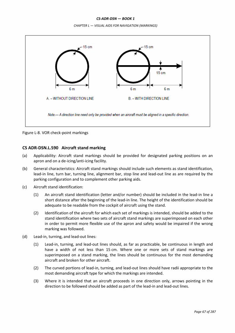
CS-ADR-DSN — BOOK 1
CHAPTER L — VISUAL AIDS FOR NAVIGATION (MARKINGS)
Page 67 of 287
Figure L-8. VOR check-point markings
CS ADR-DSN.L.590 Aircraft stand marking
(a) Applicability: Aircraft stand markings should be provided for designated parking positions on an apron and on a de-icing/anti-icing facility.
(b) General characteristics: Aircraft stand markings should include such elements as stand identification, lead-in line, turn bar, turning line, alignment bar, stop line and lead-out line as are required by the parking configuration and to complement other parking aids.
(c) Aircraft stand identification:
(1) An aircraft stand identification (letter and/or number) should be included in the lead-in line a short distance after the beginning of the lead-in line. The height of the identification should be adequate to be readable from the cockpit of aircraft using the stand.
(2) Identification of the aircraft for which each set of markings is intended, should be added to the stand identification where two sets of aircraft stand markings are superimposed on each other in order to permit more flexible use of the apron and safety would be impaired if the wrong marking was followed.
(d) Lead-in, turning, and lead-out lines:
(1) Lead-in, turning, and lead-out lines should, as far as practicable, be continuous in length and have a width of not less than 15 cm. Where one or more sets of stand markings are superimposed on a stand marking, the lines should be continuous for the most demanding aircraft and broken for other aircraft.
(2) The curved portions of lead-in, turning, and lead-out lines should have radii appropriate to the most demanding aircraft type for which the markings are intended.
(3) Where it is intended that an aircraft proceeds in one direction only, arrows pointing in the direction to be followed should be added as part of the lead-in and lead-out lines.
CS-ADR-DSN — BOOK 1
CHAPTER L — VISUAL AIDS FOR NAVIGATION (MARKINGS)
Page 68 of 287
(e) Alignment bar: An alignment bar should be placed so as to be coincident with the extended centre line of the aircraft in the specified parking position and visible to the pilot during the final part of the parking manoeuvre. It should have a width of not less than 15 cm.
(f) Turn bar and stop line:
(1) A turn bar should be located at right angles to the lead-in line, abeam the left pilot position at the point of initiation of any intended turn. It should have a length and width of not less than 6 m and 15 cm respectively, and include an arrowhead to indicate the direction of turn.
(2) A stop line should be located at right angles to the alignment bar, abeam the left pilot position at the intended point of stop. It should have a length and width of not less than 6 m and 15 cm respectively.
(3) If more than one turn bar and/or stop line is required, they should be designated for the appropriate aircraft types.
CS ADR-DSN.L.595 Apron safety lines
(a) Applicability: Apron safety lines should be provided on an apron as required by the parking configurations and ground facilities.
(b) Location: Apron safety lines should be located so as to define the areas intended for use by ground vehicles and other aircraft servicing equipment to provide safe separation from aircraft.
(c) Characteristics:
(1) Apron safety lines should include such elements as wing tip clearance lines and service road boundary lines as required by the parking configurations and ground facilities.
(2) Apron safety lines should be of a conspicuous colour which should contrast with that used for aircraft stand markings.
(3) An apron safety line should be continuous in length and at least 10 cm in width.
CS ADR-DSN.L.600 Road-holding position marking
(a) Applicability: A road-holding position marking should be provided at all road entrances to a runway.
(b) Location:
(1) The road-holding position marking should be located across the road at the holding position.
(2) Where a road intersects a taxiway, a road-holding position marking should be located across the road at the appropriate distance to ensure vehicles remain clear of the taxiway strip.
(c) Characteristics:
(1) The road-holding position marking should be in accordance with the local road traffic regulations.
(2) The road marking at the intersection of a road with a taxiway should be in accordance with the local road traffic regulations for a yield right of way.
CS ADR-DSN.L.605 Mandatory instruction marking
(a) Applicability:
(1) Where a mandatory instruction sign in accordance with CS ADR-DSN.N.780 is not installed, a mandatory instruction marking should be provided on the surface of the pavement.

CS-ADR-DSN — BOOK 1
CHAPTER L — VISUAL AIDS FOR NAVIGATION (MARKINGS)
Page 69 of 287
(2) On taxiways exceeding 60 m in width, or to assist in the prevention of a runway incursion, a mandatory instruction sign should be supplemented by a mandatory instruction marking.
(b) Location:
(1) The mandatory instruction marking on taxiways, where the code letter is A, B, C, or D, should be located across the taxiway equally placed about the taxiway centre line and on the holding side of the runway-holding position marking as shown in Figure L-9(A). The distance between the nearest edge of the marking and the runway-holding position marking or the taxiway centre line marking should be not less than 1 m.
(2) The mandatory instruction marking on taxiways where the code letter is E or F, should be located on the both sides of the taxiway centre line marking and on the holding side of the runway-holding position marking as shown in Figure L-9(B). The distance between the nearest edge of the marking and the runway-holding position marking, or the taxiway centre line marking should be not less than 1 m.
(c) Characteristics:
(1) A mandatory instruction marking should consist of an inscription in white on a red background. Except for a NO ENTRY marking, the inscription should provide information identical to that of the associated mandatory instruction sign.
(2) A NO ENTRY marking should consist of an inscription in white reading NO ENTRY on a red background.
(3) Where there is insufficient contrast between the marking and the pavement surface, the mandatory instruction marking should include an appropriate border, preferably white or black.
(4) The character height should be 4 m for inscriptions where the code letter is C, D, E, or F, and at least 2 m where the code letter is A or B. The inscription should be in the form and proportions shown in Figures L-10A to L-10E.
(5) The background should be rectangular and extend a minimum of 0.5 m laterally and vertically beyond the extremities of the inscription.
CS ADR-DSN.L.610 Information marking
(a) Applicability: Where an information sign in accordance with CS ADR-DSN.N.785 is not installed, an information marking should be displayed on the surface of the pavement.
(b) Characteristics:
(1) An information marking should consist of:
(i) an inscription in yellow upon a black background when it replaces or supplements a location sign; and
(ii) an inscription in black upon a yellow background when it replaces or supplements a direction or destination sign.
(2) Where there is insufficient contrast between the marking background and the pavement surface, the marking should include:
(i) a black border where the inscriptions are in black; and
(ii) a yellow border where the inscriptions are in yellow.
(3) The character height should be as for mandatory instruction markings.

CS-ADR-DSN — BOOK 1
CHAPTER L — VISUAL AIDS FOR NAVIGATION (MARKINGS)
Page 70 of 287
Figure L-9. Mandatory instruction marking

CS-ADR-DSN — BOOK 1
CHAPTER L — VISUAL AIDS FOR NAVIGATION (MARKINGS)
Page 71 of 287
Figure L-10A. Mandatory instruction marking inscription form and proportions

CS-ADR-DSN — BOOK 1
CHAPTER L — VISUAL AIDS FOR NAVIGATION (MARKINGS)
Page 72 of 287
Figure L-10B. Mandatory instruction marking inscription form and proportions

CS-ADR-DSN — BOOK 1
CHAPTER L — VISUAL AIDS FOR NAVIGATION (MARKINGS)
Page 73 of 287
Figure L-10C. Mandatory instruction marking inscription form and proportions

CS-ADR-DSN — BOOK 1
CHAPTER L — VISUAL AIDS FOR NAVIGATION (MARKINGS)
Page 74 of 287
Figure L-10D. Mandatory instruction marking inscription form and proportions

CS-ADR-DSN — BOOK 1
CHAPTER L — VISUAL AIDS FOR NAVIGATION (MARKINGS)
Page 75 of 287
Figure L-10E. Mandatory instruction marking inscription form and proportions

CS-ADR-DSN — BOOK 1
CHAPTER M — VISUAL AIDS FOR NAVIGATION (LIGHTS)
Page 76 of 287
CHAPTER M — VISUAL AIDS FOR NAVIGATION (LIGHTS)
CS ADR-DSN.M.615 General
(a) Elevated approach lights:
(1) Elevated approach lights and their supporting structures should be frangible except that, in that portion of the approach lighting system beyond 300 m from the threshold:
(i) where the height of a supporting structure exceeds 12 m, the frangibility requirement should apply to the top 12 m only; and
(ii) where a supporting structure is surrounded by non-frangible objects, only that part of the structure that extends above the surrounding objects should be frangible.
(2) When an approach light fixture or supporting structure is not in itself sufficiently conspicuous, it should be suitably marked.
(b) Elevated lights:
Elevated runway, stopway, and taxiway lights should be frangible. Their height should be sufficiently
low to preserve clearance for propellers and for the engine pods of jet aircraft.
(c) Surface lights:
(1) Light fixtures inset in the surface of runways, stopways, taxiways, and aprons should be so designed and fitted as to withstand being run over by the wheels of an aircraft without damage either to the aircraft or to the lights themselves.
(2) The temperature produced by conduction or radiation at the interface between an installed inset light and an aircraft tire should not exceed 160°C during a 10-minute period of exposure.
(d) Light intensity and control:
(1) The intensity of runway lighting should be adequate for the minimum conditions of visibility and ambient light in which use of the runway is intended, and compatible with that of the nearest section of the approach lighting system when provided.
(2) Where a high-intensity lighting system is provided, a suitable intensity control should be incorporated to allow for adjustment of the light intensity to meet the prevailing conditions. Separate intensity controls or other suitable methods should be provided to ensure that the following systems when installed, can be operated at compatible intensities:
(i) approach lighting system;
(ii) runway edge lights;
(iii) runway threshold lights;
(iv) runway end lights;
(v) runway centre line lights;
(vi) runway touchdown zone lights; and
(vii) taxiway centre line lights.
(3) On the perimeter of and within the ellipse defining the main beam in CS ADR-DSN.U.940, the maximum light intensity value should not be greater than three times the minimum light intensity value measured in accordance with CS ADR-DSN.U.940.
CS-ADR-DSN — BOOK 1
CHAPTER M — VISUAL AIDS FOR NAVIGATION (LIGHTS)
Page 77 of 287
On the perimeter of and within the rectangle defining the main beam in CS ADR-DSN.U.940, the maximum light intensity value should not be greater than three times the minimum light intensity value measured in accordance with CS ADR-DSN.U.940.
CS ADR-DSN.M.620 Aeronautical beacons
(a) General
(1) When operationally necessary an aerodrome beacon or identification beacon should be provided at each aerodrome intended for use at night.
(2) The operational requirement should be determined having regard to the requirements of the air traffic using the aerodrome, the conspicuity of the aerodrome features in relation to its surroundings, and the installation of other visual and non-visual aids useful in locating the aerodrome.
(b) Aerodrome beacon
(1) Applicability
An aerodrome beacon should be provided at an aerodrome intended for use at night if aircraft
navigate predominantly by visual means and one or more of the following conditions exist:
(i) reduced visibilities are frequent; or
(ii) it is difficult to locate the aerodrome from the air due to surrounding lights or terrain.
(2) Location
(i) The aerodrome beacon should be located on or adjacent to the aerodrome in an area of low ambient background lighting.
(ii) The location of the beacon should be such that the beacon is not shielded by objects in significant directions and does not dazzle a pilot approaching to land.
(3) Characteristics
(i) The aerodrome beacon should show either coloured flashes alternating with white flashes or white flashes only.
(ii) The frequency of total flashes should be from 20 to 30 per minute.
(iii) The light from the beacon should show at all angles of azimuth. The vertical light distribution should extend upwards from an elevation of not more than 1° to an elevation sufficient to provide guidance at the maximum elevation at which the beacon is intended to be used, and the effective intensity of the flash should be not less than 2 000 cd.
(iv) At locations where a high ambient background lighting level cannot be avoided, the effective intensity of the flash should be required to be increased by a factor up to a value of 10.
(c) Identification beacon
(1) Applicability
An identification beacon should be provided at an aerodrome which is intended for use at night and
cannot be easily identified from the air by other means.
(2) Location

CS-ADR-DSN — BOOK 1
CHAPTER M — VISUAL AIDS FOR NAVIGATION (LIGHTS)
Page 78 of 287
(i) The identification beacon should be located on the aerodrome in an area of low ambient background lighting.
(ii) The location of the beacon should be such that the beacon is not shielded by objects in significant directions and does not dazzle a pilot approaching to land.
(3) Characteristics
(i) An identification beacon at a land aerodrome should show at all angles of azimuth. The vertical light distribution should extend upwards from an elevation of not more than 1° to an elevation sufficient to provide guidance at the maximum elevation at which the beacon is intended to be used, and the effective intensity of the flash should be not less than 2 000 cd.
(ii) At locations where a high ambient background lighting level cannot be avoided, the effective intensity of the flash should be required to be increased by a factor up to a value of 10.
(iii) An identification beacon should show flashing-green.
(iv) The identification characters should be transmitted in the International Morse Code.
(v) The speed of transmission should be between six and eight words per minute, the corresponding range of duration of the Morse dots being from 0.15 to 0.2 seconds per dot.
SECTION 1 — APPROACH LIGHTING SYSTEMS
CS ADR-DSN.M.625 Approach lighting systems, general and applicability
(a) The safety objective of the approach lighting system is to provide visual guidance for alignment and roll, and limited distance-to-go information to enable safe approach to a runway.
(b) Non-instrument runway
Where physically practicable, a simple approach lighting system as specified in CS ADR-DSN.M.626 should be provided to serve a non-instrument runway where the code number is 3 or 4, and intended for use at night, except when the runway is used only in conditions of good visibility, and sufficient guidance is provided by other visual aids.
(c) Non-precision approach runway
Where physically practicable, a simple approach lighting system specified in CS ADR-DSN.M.626 should be provided to serve a non-precision approach runway, except when the runway is used only in conditions of good visibility or sufficient guidance is provided by other visual aids.
(d) Precision approach runway category I
Where physically practicable, a precision approach category I lighting system as specified in CS ADR-DSN.M.630 should be provided to serve a precision approach runway category I.
(e) Precision approach runway categories II and III
A precision approach category II and III lighting system as specified in CS ADR-DSN.M.635 should be provided to serve a precision approach runway category II or III.

CS-ADR-DSN — BOOK 1
CHAPTER M — VISUAL AIDS FOR NAVIGATION (LIGHTS)
Page 79 of 287
CS ADR-DSN.M.626 Simple approach lighting systems
(a) Location and composition:
(i) A simple approach lighting system should consist of a row of lights on the extended centre line of the runway extending whenever possible, over a distance of not less than 420 m from the threshold with a row of lights forming a crossbar 18 m or 30 m in length at a distance of 300 m from the threshold.
(ii) The certification specifications, as prescribed in Book 1 provide for the basic characteristics for simple approach lighting systems. For certain aspects of these systems, some latitude is permitted, for example, in the spacing between centre line lights and crossbars.
(b) Crossbar lights:
(1) The lights forming the crossbar should be as close as practicable in a horizontal straight line at right angles to, and bisected by, the line of the centre line lights.
(2) The lights of the crossbar should be spaced so as to produce a linear effect, except that, when a crossbar of 30 m is used, gaps may be left on each side of the centre line. These gaps should be kept to a minimum to meet local requirements, and each should not exceed 6 m.
(3) Spacing for the crossbar lights between 1 m and 4 m are in use. Gaps on each side of the centre line may improve directional guidance when approaches are made with a lateral error, and facilitate the movement of rescue and firefighting vehicles.
(c) Centre line lights:
(1) The lights forming the centre line should be placed at longitudinal intervals of 60 m, except that when it is desired to improve the guidance, an interval of 30 m may be used.
(2) The innermost light should be located either 60 m or 30 m from the threshold, depending on the longitudinal interval selected for the centre line lights. If it is not physically possible to provide a centre line extending for a distance of 420 m from the threshold, it should be extended to 300 m so as to include the crossbar. If this is not possible, the centre line lights should be extended as far as practicable, and each centre line light should then consist of a barrette at least 3 m in length. Subject to the approach system having a crossbar at 300 m from the threshold, an additional crossbar may be provided at 150 m from the threshold.
(3) The system should lie as nearly as practicable in the horizontal plane passing through the threshold, provided that:
(i) no object other than an ILS or MLS azimuth antenna should protrude through the plane of the approach lights within a distance of 60 m from the centre line of the system; and
(ii) no light other than a light located within the central part of a crossbar or a centre line barrette, excluding their extremities, should be screened from an approaching aircraft.
Any ILS or MLS azimuth antenna protruding through the plane of the lights should be treated as an obstacle, and marked and lighted accordingly as specified in the requirements for obstacle marking and lighting.
(d) Characteristics:
(1) The lights of a simple approach lighting system should be fixed lights and the colour of the lights should be such as to ensure that the system is readily distinguishable from other aeronautical ground lights, and from extraneous lighting if present, but should be preferably fixed lights showing variable white. Each centre line light should consist of either:

CS-ADR-DSN — BOOK 1
CHAPTER M — VISUAL AIDS FOR NAVIGATION (LIGHTS)
Page 80 of 287
(i) a single source; or
(ii) a barrette at least 3 m in length.
(e) Barrettes of 4 m in length should be so designed if it is anticipated that the simple approach lighting system should be developed into a precision approach lighting system.
(f) Where provided for a non-instrument runway, the lights should show at all angles in azimuth necessary to a pilot on base leg and final approach. The intensity of the lights should be adequate for all conditions of visibility and ambient light for which the system has been provided.
(g) Where provided for a non-precision approach runway, the lights should show at all angles in azimuth necessary to the pilot of an aircraft which on final approach does not deviate by an abnormal amount from the path defined by the non-visual aid. The lights should be designed to provide guidance during both day and night in the most adverse conditions of visibility and ambient light for which it is intended that the system should remain usable.

CS-ADR-DSN — BOOK 1
CHAPTER M — VISUAL AIDS FOR NAVIGATION (LIGHTS)
Page 81 of 287
Figure M-1. Simple approach lighting systems
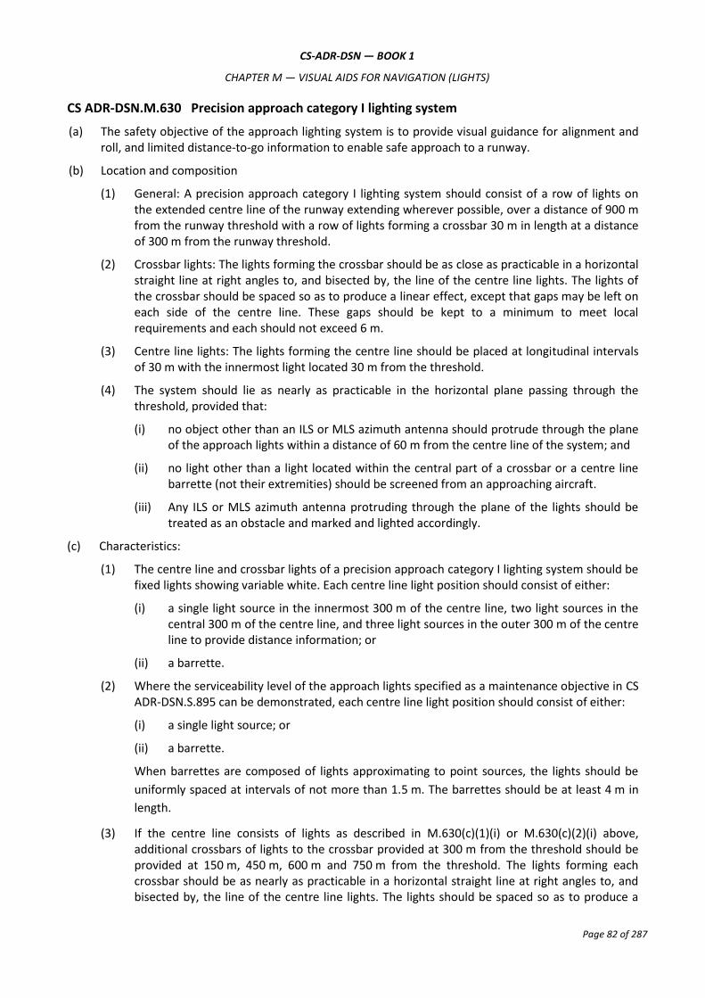
CS-ADR-DSN — BOOK 1
CHAPTER M — VISUAL AIDS FOR NAVIGATION (LIGHTS)
Page 82 of 287
CS ADR-DSN.M.630 Precision approach category I lighting system
(a) The safety objective of the approach lighting system is to provide visual guidance for alignment and roll, and limited distance-to-go information to enable safe approach to a runway.
(b) Location and composition
(1) General: A precision approach category I lighting system should consist of a row of lights on the extended centre line of the runway extending wherever possible, over a distance of 900 m from the runway threshold with a row of lights forming a crossbar 30 m in length at a distance of 300 m from the runway threshold.
(2) Crossbar lights: The lights forming the crossbar should be as close as practicable in a horizontal straight line at right angles to, and bisected by, the line of the centre line lights. The lights of the crossbar should be spaced so as to produce a linear effect, except that gaps may be left on each side of the centre line. These gaps should be kept to a minimum to meet local requirements and each should not exceed 6 m.
(3) Centre line lights: The lights forming the centre line should be placed at longitudinal intervals of 30 m with the innermost light located 30 m from the threshold.
(4) The system should lie as nearly as practicable in the horizontal plane passing through the threshold, provided that:
(i) no object other than an ILS or MLS azimuth antenna should protrude through the plane of the approach lights within a distance of 60 m from the centre line of the system; and
(ii) no light other than a light located within the central part of a crossbar or a centre line barrette (not their extremities) should be screened from an approaching aircraft.
(iii) Any ILS or MLS azimuth antenna protruding through the plane of the lights should be treated as an obstacle and marked and lighted accordingly.
(c) Characteristics:
(1) The centre line and crossbar lights of a precision approach category I lighting system should be fixed lights showing variable white. Each centre line light position should consist of either:
(i) a single light source in the innermost 300 m of the centre line, two light sources in the central 300 m of the centre line, and three light sources in the outer 300 m of the centre line to provide distance information; or
(ii) a barrette.
(2) Where the serviceability level of the approach lights specified as a maintenance objective in CS ADR-DSN.S.895 can be demonstrated, each centre line light position should consist of either:
(i) a single light source; or
(ii) a barrette.
When barrettes are composed of lights approximating to point sources, the lights should be
uniformly spaced at intervals of not more than 1.5 m. The barrettes should be at least 4 m in
length.
(3) If the centre line consists of lights as described in M.630(c)(1)(i) or M.630(c)(2)(i) above, additional crossbars of lights to the crossbar provided at 300 m from the threshold should be provided at 150 m, 450 m, 600 m and 750 m from the threshold. The lights forming each crossbar should be as nearly as practicable in a horizontal straight line at right angles to, and bisected by, the line of the centre line lights. The lights should be spaced so as to produce a

CS-ADR-DSN — BOOK 1
CHAPTER M — VISUAL AIDS FOR NAVIGATION (LIGHTS)
Page 83 of 287
linear effect, except that gaps may be left on each side of the centre line. These gaps should be kept to a minimum to meet local requirements and each should not exceed 6 m.
(4) Where the additional crossbars are incorporated in the system, the outer ends of the crossbars should lie on two straight lines that either are parallel to the line of the centre line lights or converge to meet the runway centre line 300 m upwind from threshold.
(5) The chromaticity and characteristics of lights should be in accordance with the specifications of CS ADR-DSN.U.930 and CS ADR-DSN.U.940.
(6) If the centre line consists of barrettes as described in M.630(c)(1)(ii) or M.630(c)(2)(ii), each barrette should be supplemented by a capacitor discharge light, except where such lighting is considered unnecessary taking into account the characteristics of the system, and the nature of the meteorological conditions.
(7) Each capacitor discharge light as described in M.630(c)(6) should be flashed twice a second in sequence, beginning with the outermost light and progressing toward the threshold to the innermost light of the system. The design of the electrical circuit should be such that these lights can be operated independently of the other lights of the approach lighting system.
Figure M-2. Precision approach category I lighting systems
CS ADR-DSN.M.635 Precision approach category II and III lighting system
(a) Location and composition:
(1) The approach lighting system should consist of a row of lights on the extended centre line of the runway, extending wherever possible, over a distance of 900 m from the runway threshold. In addition, the system should have two side rows of lights, extending 270 m from the threshold, and two crossbars, one at 150 m and one at 300 m from the threshold, all as shown in Figure M-3A. Where the serviceability level of the approach lights specified as

CS-ADR-DSN — BOOK 1
CHAPTER M — VISUAL AIDS FOR NAVIGATION (LIGHTS)
Page 84 of 287
maintenance objectives in CS ADR-DSN.S.895 can be demonstrated, the system may have two side rows of lights extending 240 m from the threshold, and two crossbars, one at 150 m, and one at 300 m from the threshold, all as shown in Figure M-3B.
(2) The lights forming the centre line should be placed at longitudinal intervals of 30 m with the innermost lights located 30 m from the threshold.
(3) The lights forming the side rows should be placed on each side of the centre line, at a longitudinal spacing equal to that of the centre line lights and with the first light located 30 m from the threshold. Where the serviceability level of the approach lights specified as maintenance objectives can be demonstrated, lights forming the side rows may be placed on each side of the centre line, at a longitudinal spacing of 60 m with the first light located 60 m from the threshold. The lateral spacing (or gauge) between the innermost lights of the side rows should be not less than 18 m nor more than 22.5 m, and preferably 18 m, but in any event should be equal to that of the touchdown zone lights.
(4) The crossbar provided at 150 m from the threshold should fill in the gaps between the centre line and side row lights.
(5) The crossbar provided at 300 m from the threshold should extend on both sides of the centre line lights to a distance of 15 m from the centre line.
(6) If the centre line beyond a distance of 300 m from the threshold consists of lights as described in M.635(b)(2)(ii) and M.635(b)(2)(ii) below, additional crossbars of lights should be provided at 450 m, 600 m and 750 m from the threshold. Where such additional crossbars are incorporated in the system, the outer ends of these crossbars should lie on two straight lines that either are parallel to the centre line or converge to meet the runway centre line 300 m from the threshold.
(7) The system should lie as nearly as practicable in the horizontal plane passing through the threshold, provided that:
(i) no object other than an ILS or MLS azimuth antenna should protrude through the plane of the approach lights within a distance of 60 m from the centre line of the system; and
(ii) no light other than a light located within the central part of a crossbar or a centre line barrette (not their extremities) should be screened from an approaching aircraft.
(iii) Any ILS or MLS azimuth antenna protruding through the plane of the lights should be treated as an obstacle and marked and lighted accordingly.
(b) Characteristics:
(1) The centre line of a precision approach category II and III lighting system for the first 300 m from the threshold should consist of barrettes showing variable white, except that where the threshold is displaced 300 m or more, the centre line may consist of single light sources showing variable white. Where the serviceability level of the approach lights specified in CS ADR.DSN.S.895 can be demonstrated, the centre line of a precision approach category II and III lighting system for the first 300 m from the threshold may consist of:
(1) barrettes where the centre line beyond 300 m from the threshold consists of barrettes as described in M.635(b)(3)(i); or
(2) alternate single light sources and barrettes, where the centre line beyond 300 m from the threshold consists of single light sources as described in M.635(b)(3)(ii) below, with the innermost single light source located 30 m and the innermost barrette located 60 m from the threshold; or

CS-ADR-DSN — BOOK 1
CHAPTER M — VISUAL AIDS FOR NAVIGATION (LIGHTS)
Page 85 of 287
(3) single light sources where the threshold is displaced 300 m or more;
all of which should show variable white.
(2) Beyond 300 m from the threshold each centre line light position should consist of either:
(i) a barrette as used on the inner 300 m; or
(ii) two light sources in the central 300 m of the centre line, and three light sources in the outer 300 m of the centre line;
all of which should show variable white.
(3) Where the serviceability level of the approach lights in CS ADR.DSN.S.895 as maintenance objectives can be demonstrated beyond 300 m from the threshold, each centre line light position may consist of either:
(i) a barrette; or
(ii) a single light source;
all of which should show variable white.
(4) The barrettes should be at least 4 m in length. When barrettes are composed of lights approximating to point sources, the lights should be uniformly spaced at intervals of not more than 1.5 m.
(5) If the centre line beyond 300 m from the threshold consists of barrettes as described in
M.635(b)(2)(i) and M.635(b)(3)(i), each barrette beyond 300 m should be supplemented by a
capacitor discharge light, except where such lighting is considered unnecessary taking into
account the characteristics of the system and the nature of the meteorological conditions.
(6) Each capacitor discharge light should be flashed twice a second in sequence, beginning with the outermost light and progressing toward the threshold to the innermost light of the system. The design of the electrical circuit should be such that these lights can be operated independently of the other lights of the approach lighting system.
(7) The side row should consist of barrettes showing red. The length of a side row barrette and the spacing of its lights should be equal to those of the touchdown zone light barrettes.
(8) The lights forming the crossbars should be fixed lights showing variable white. The lights should be uniformly spaced at intervals of not more than 2.7 m.
(9) The intensity of the red lights should be compatible with the intensity of the white lights.
(10) The lights should be in accordance with the specifications of CS ADR-DSN.U.940, Figures U-5 and U-6.

CS-ADR-DSN — BOOK 1
CHAPTER M — VISUAL AIDS FOR NAVIGATION (LIGHTS)
Page 86 of 287
Figure M-3A. Inner 300 m approach and runway lighting for precision approach runways, categories II and
III
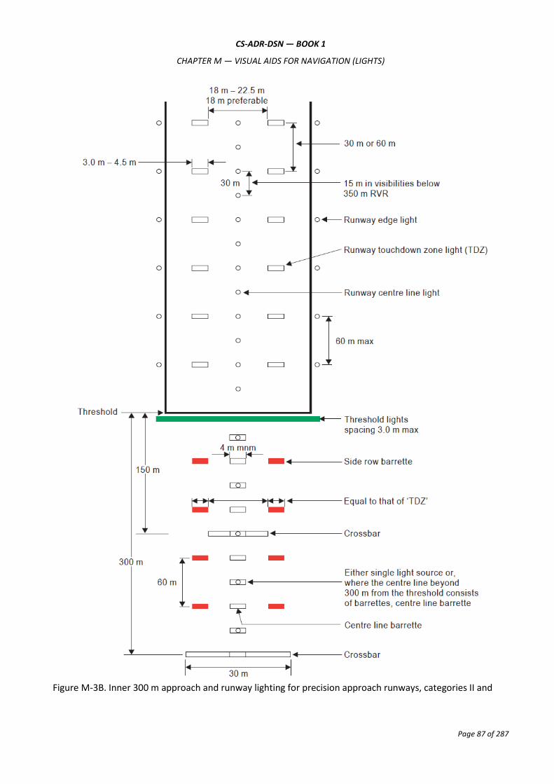
CS-ADR-DSN — BOOK 1
CHAPTER M — VISUAL AIDS FOR NAVIGATION (LIGHTS)
Page 87 of 287
Figure M-3B. Inner 300 m approach and runway lighting for precision approach runways, categories II and

CS-ADR-DSN — BOOK 1
CHAPTER M — VISUAL AIDS FOR NAVIGATION (LIGHTS)
Page 88 of 287
III where the serviceability levels of the lights specified as maintenance objectives in CS ADR-DSN.S.895 can
be demonstrated
SECTION 2 — VISUAL APPROACH SLOPE INDICATOR SYSTEMS
CS ADR-DSN.M.640 Visual approach slope indicator systems
The safety objective of visual approach slope indicators is to provide information on the approach angle
necessary to maintain a safe height over obstacles and threshold.
(a) A visual approach slope indicator system should be provided to serve the approach to a runway where one or more of the following conditions exist:
(1) the runway is used by turbojet or other aeroplanes with similar approach guidance requirements;
(2) the pilot of any type of aeroplane may have difficulty in judging the approach due to:
(i) inadequate visual guidance such as is experienced during an approach over water or featureless terrain by day or in the absence of sufficient extraneous lights in the approach area by night; or
(ii) misleading information such as is produced by deceptive surrounding terrain or runway slopes.
(3) the presence of objects in the approach area may involve serious hazard if an aeroplane descends below the normal approach path, particularly if there are no non-visual or other visual aids to give warning of such objects;
(4) physical conditions at either end of the runway present a serious hazard in the event of an aeroplane undershooting or overrunning the runway; and
(5) terrain or prevalent meteorological conditions are such that the aeroplane may be subjected to unusual turbulence during approach.
(b) The standard visual approach slope indicator systems should consist of PAPI and APAPI systems conforming to the specifications, as prescribed in CS ADR-DSN.M.645 to CS ADR-DSN.M.655.
(c) PAPI should be provided where the code number is 3 or 4 when one or more of the conditions specified in paragraph (a) above exist.
(d) PAPI or APAPI should be provided where the code number is 1 or 2 when one or more of the conditions specified in paragraph (a) above exist.
CS ADR-DSN.M.645 PAPI and APAPI
(a) A PAPI or APAPI should be provided as prescribed in Section 2 — Visual approach slope indicator
systems.
(b) Definition and positioning:
The PAPI system should consist of a wing bar of 4 sharp transition multi-lamp (or paired single lamp) units equally spaced and the APAPI system shall consist of a wing bar of 2 sharp transition multi-lamp (or paired single lamp) units. The system should be located on the left side of the runway unless it is physically impracticable to do so. Where a runway is used by aircraft requiring visual roll guidance

CS-ADR-DSN — BOOK 1
CHAPTER M — VISUAL AIDS FOR NAVIGATION (LIGHTS)
Page 89 of 287
which is not provided by other external means, then a second wing bar may be provided on the opposite side of the runway for PAPI or APAPI.
(1) The APAPI system should consist of a wing bar of 2 sharp transition multi-lamp (or paired single lamp) units. The system should be located on the left side of the runway unless it is physically impracticable to do so.
(2) The wing bar of a PAPI should be constructed and arranged in such a manner that a pilot making an approach should:
(i) when on or close to the approach slope, see the two units nearest the runway as red and the two units farthest from the runway as white;
(ii) when above the approach slope, see the one unit nearest the runway as red and the three units farthest from the runway as white; and when further above the approach slope, see all the units as white; and
(iii) when below the approach slope, see the three units nearest the runway as red and the unit farthest from the runway as white; and when further below the approach slope, see all the units as red.
(3) The wing bar of an APAPI should be constructed and arranged in such a manner that a pilot making an approach should:
(i) when on or close to the approach slope, see the unit nearer the runway as red and the unit farther from the runway as white;
(ii) when above the approach slope, see both the units as white; and
(iii) when below the approach slope, see both the units as red.
(4) The light units should be located as in the basic configuration illustrated in Figure M-4, subject to the installation tolerances given below. The units forming a wing bar should be mounted so as to appear to the pilot of an approaching aeroplane to be substantially in a horizontal line. The light units should be mounted as low as possible and should be frangible.
(c) Characteristics:
(1) The system should be suitable for both day and night operations.
(2) Colour:
(i) The colour transition from red to white in the vertical plane should be such as to appear to an observer, at a distance of not less than 300 m, to occur within a vertical angle of not more than 3´.
(ii) At full intensity the red light should have a Y coordinate not exceeding 0.320.
(3) Intensity:
(i) The light intensity distribution of the light units should be as shown in CS ADR-DSN.U.940.
(ii) Suitable intensity control should be provided so as to allow adjustment to meet the prevailing conditions and to avoid dazzling the pilot during approach and landing.
(4) Light orientation: Each light unit should be capable of adjustment in elevation so that the lower limit of the white part of the beam may be fixed at any desired angle of elevation between 1°30´and at least 4°30´above the horizontal.
(5) Other characteristics: The light units should be so designed that deposits of condensation, snow, ice, dirt, or other contaminants, on optically transmitting or reflecting surfaces should

CS-ADR-DSN — BOOK 1
CHAPTER M — VISUAL AIDS FOR NAVIGATION (LIGHTS)
Page 90 of 287
interfere to the least possible extent with the light signals and should not affect the contrast between the red and white signals and the elevation of the transition sector.
Figure M-4. Siting of PAPI and APAPI

CS-ADR-DSN — BOOK 1
CHAPTER M — VISUAL AIDS FOR NAVIGATION (LIGHTS)
Page 91 of 287
CS ADR-DSN.M.650 Approach slope and elevation setting of light units
(a) Approach slope:
(1) The approach slope as defined in Figure M-5, should be used by the aeroplanes in the approach.
(2) When the runway is equipped with an ILS and/or MLS, the siting and the angle of elevation of the light units should be such that the visual approach slope conforms as closely as possible with the glide path of the ILS and/or the minimum glide path of the MLS, as appropriate.
(b) Elevation setting of light units
(1) The angle of elevation settings of the light units in a PAPI wing bar should be such that, during an approach, the pilot of an aeroplane observing a signal of one white and three reds should clear all objects in the approach area by a safe margin (see Table M-1).
(2) The angle of elevation settings of the light units in an APAPI wing bar should be such that, during an approach, the pilot of an aeroplane observing the lowest on-slope signal, i.e. one white and one red, should clear all objects in the approach area by a safe margin (see Table M-1).
(3) The azimuth spread of the light beam should be suitably restricted where an object located outside the obstacle protection surface of the PAPI or APAPI system but within the lateral limits of its light beam, is found to extend above the plane of the obstacle protection surface and an safety assessment indicates that the object could adversely affect the safety of operations. The extent of the restriction should be such that the object remains outside the confines of the light beam.
(4) Where wing bars are installed on each side of the runway to provide roll guidance, corresponding units should be set at the same angle so that the signals of each wing bar change symmetrically at the same time.

CS-ADR-DSN — BOOK 1
CHAPTER M — VISUAL AIDS FOR NAVIGATION (LIGHTS)
Page 92 of 287
Figure M-5. Light beams and angle of elevation setting of PAPI and APAPI
CS ADR-DSN.M.655 Obstacle protection surface for PAPI and APAPI
(a) Applicability:
An obstacle protection surface should be established when it is intended to provide a visual approach slope indicator system.
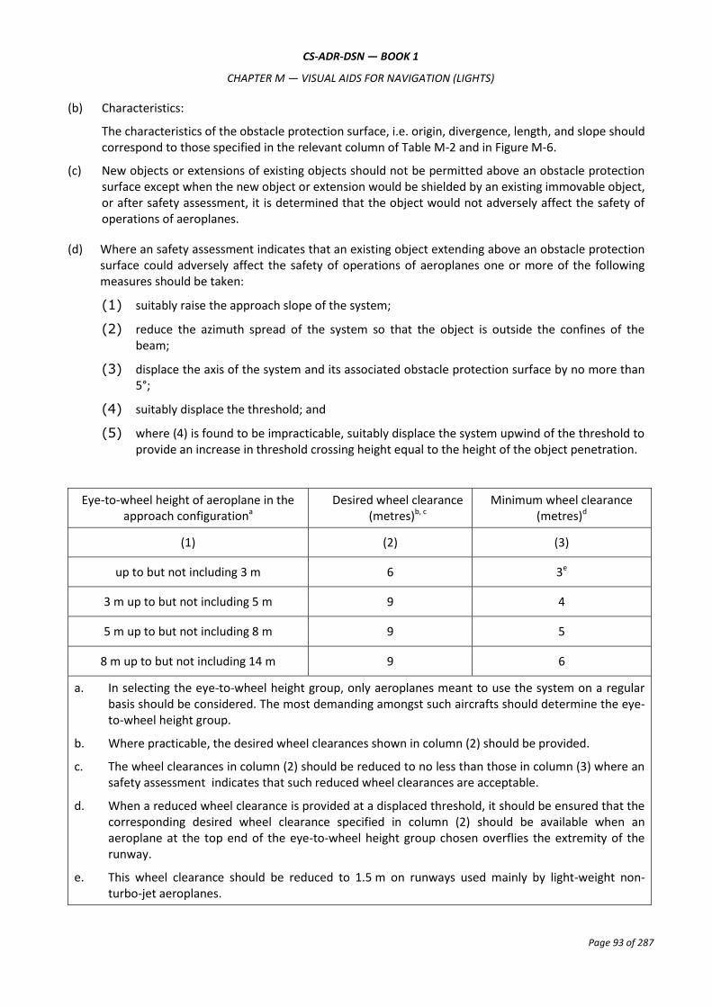
CS-ADR-DSN — BOOK 1
CHAPTER M — VISUAL AIDS FOR NAVIGATION (LIGHTS)
Page 93 of 287
(b) Characteristics:
The characteristics of the obstacle protection surface, i.e. origin, divergence, length, and slope should correspond to those specified in the relevant column of Table M-2 and in Figure M-6.
(c) New objects or extensions of existing objects should not be permitted above an obstacle protection surface except when the new object or extension would be shielded by an existing immovable object, or after safety assessment, it is determined that the object would not adversely affect the safety of operations of aeroplanes.
(d) Where an safety assessment indicates that an existing object extending above an obstacle protection surface could adversely affect the safety of operations of aeroplanes one or more of the following measures should be taken:
(1) suitably raise the approach slope of the system;
(2) reduce the azimuth spread of the system so that the object is outside the confines of the beam;
(3) displace the axis of the system and its associated obstacle protection surface by no more than 5°;
(4) suitably displace the threshold; and
(5) where (4) is found to be impracticable, suitably displace the system upwind of the threshold to provide an increase in threshold crossing height equal to the height of the object penetration.
Eye-to-wheel height of aeroplane in the approach configurationa
Desired wheel clearance (metres)b, c
Minimum wheel clearance (metres)d
(1) (2) (3)
up to but not including 3 m 6 3e
3 m up to but not including 5 m 9 4
5 m up to but not including 8 m 9 5
8 m up to but not including 14 m 9 6
a. In selecting the eye-to-wheel height group, only aeroplanes meant to use the system on a regular basis should be considered. The most demanding amongst such aircrafts should determine the eye-to-wheel height group.
b. Where practicable, the desired wheel clearances shown in column (2) should be provided.
c. The wheel clearances in column (2) should be reduced to no less than those in column (3) where an safety assessment indicates that such reduced wheel clearances are acceptable.
d. When a reduced wheel clearance is provided at a displaced threshold, it should be ensured that the corresponding desired wheel clearance specified in column (2) should be available when an aeroplane at the top end of the eye-to-wheel height group chosen overflies the extremity of the runway.
e. This wheel clearance should be reduced to 1.5 m on runways used mainly by light-weight non-turbo-jet aeroplanes.
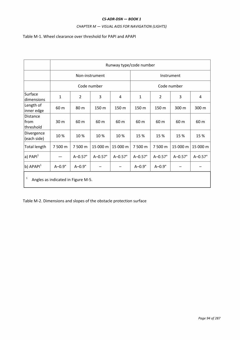
CS-ADR-DSN — BOOK 1
CHAPTER M — VISUAL AIDS FOR NAVIGATION (LIGHTS)
Page 94 of 287
Table M-1. Wheel clearance over threshold for PAPI and APAPI
Runway type/code number
Non-instrument Instrument
Code number Code number
Surface dimensions
1 2 3 4 1 2 3 4
Length of inner edge
60 m 80 m 150 m 150 m 150 m 150 m 300 m 300 m
Distance from threshold
30 m 60 m 60 m 60 m 60 m 60 m 60 m 60 m
Divergence (each side)
10 % 10 % 10 % 10 % 15 % 15 % 15 % 15 %
Total length 7 500 m 7 500 m 15 000 m 15 000 m 7 500 m 7 500 m 15 000 m 15 000 m
a) PAPI1 ― A–0.57° A–0.57° A–0.57° A–0.57° A–0.57° A–0.57° A–0.57°
b) APAPI1 A–0.9° A–0.9° – – A–0.9° A–0.9° – –
1 Angles as indicated in Figure M-5.
Table M-2. Dimensions and slopes of the obstacle protection surface

CS-ADR-DSN — BOOK 1
CHAPTER M — VISUAL AIDS FOR NAVIGATION (LIGHTS)
Page 95 of 287
Figure M-6. Obstacle protection surface for visual approach slope indicator systems
CS ADR-DSN.M.660 Circling guidance lights
(a) Applicability: Circling guidance lights should be provided when existing approach and runway lighting systems do not satisfactorily permit identification of the runway and/or approach area to a circling aircraft that are intending to carry out circling approaches.
(b) Location and positioning:
(1) The location and number of circling guidance lights should be adequate to enable a pilot, as appropriate, to:
(i) join the downwind leg or align and adjust the aircraft’s track to the runway at a required distance from it and to distinguish the threshold in passing; and
(ii) keep in sight the runway threshold and/or other features which should make it possible to judge the turn on to base leg and final approach, taking into account the guidance provided by other visual aids.
(2) Circling guidance lights should consist of:
(i) lights indicating the extended centre line of the runway and/or parts of any approach lighting system; or
(ii) lights indicating the position of the runway threshold; or
M-2)

CS-ADR-DSN — BOOK 1
CHAPTER M — VISUAL AIDS FOR NAVIGATION (LIGHTS)
Page 96 of 287
(iii) lights indicating the direction or location of the runway;
or a combination of such lights as is appropriate to the runway under consideration.
(c) Characteristics:
(1) Circling guidance lights should be fixed or flashing lights of an intensity and beam spread adequate for the conditions of visibility and ambient light in which it is intended to make visual circling approaches. The flashing lights should be white, and the steady lights either white or gaseous discharge lights.
(2) The lights should be designed and be installed in such a manner that they should not dazzle or confuse a pilot when approaching to land, taking off, or taxiing.
SECTION 3 — RUNWAY & TAXIWAY LIGHTS
CS ADR-DSN.M.665 Runway lead-in lighting systems
(a) Applicability: A runway lead-in lighting system should be provided to avoid hazardous terrain.
(b) Location and positioning
(1) A runway lead-in lighting system should consist of groups of lights positioned:
(i) so as to define the desired approach path. Runway lead-in lighting systems may be curved, straight, or a combination thereof; and
(ii) so that one group should be sighted from the preceding group.
(2) The interval between adjacent groups should not exceed approximately 1 600 m.
(3) A runway lead-in lighting system should extend from a determined point up to a point where the approach lighting system if provided, or the runway lighting system is in view.
(4) Each group of lights of a runway lead-in lighting system should consist of at least three flashing lights in a linear or cluster configuration. The system should be augmented by steady burning lights where such lights would assist in identifying the system.
(c) Characteristics: The flashing lights should be white, and the steady burning lights should be gaseous discharge lights.
CS ADR-DSN.M.670 Runway threshold identification lights
(a) Location and positioning: Where provided, runway threshold identification lights should be located symmetrically about the runway centre line, in line with the threshold and approximately 10 m outside each line of runway edge lights.
(b) Characteristics: The lights should be visible only in the direction of approach to the runway.

CS-ADR-DSN — BOOK 1
CHAPTER M — VISUAL AIDS FOR NAVIGATION (LIGHTS)
Page 97 of 287
CS ADR-DSN.M.675 Runway edge lights
(a) Applicability:
(1) Runway edge lights should be provided for a runway intended for use at night or for a precision approach runway intended for use by day or night.
(2) Runway edge lights should be provided on a runway intended for take-off with an operating minimum below an RVR of the order of 800 m by day.
(b) Location and positioning:
(1) Runway edge lights should be placed along the full length of the runway and should be in two parallel rows equidistant from the centre line.
(2) Runway edge lights should be placed along the edges of the area declared for use as the runway or outside the edges of the area at a distance of not more than 3 m.
(3) Where the width of the area which could be declared as runway, exceeds 60 m, the distance between the rows of lights should be determined taking into account the nature of the operations, the light distribution characteristics of the runway edge lights, and other visual aids serving the runway.
(4) The lights should be uniformly spaced in rows at intervals of not more than 60 m for an instrument runway, and at intervals of not more than 100 m for a non-instrument runway. The lights on opposite sides of the runway axis should be on lines at right angles to that axis. At intersections of runways, lights may be spaced irregularly or omitted, provided that adequate guidance remains available to the pilot.
(c) Characteristics:
(1) Runway edge lights should be fixed lights showing variable white, except that:
(i) in the case of a displaced threshold, the lights between the beginning of the runway and the displaced threshold should show red in the approach direction; and
(ii) a section of the lights 600 m or one-third of the runway length, whichever is the less, at the remote end of the runway from the end at which the take-off run is started, should show yellow.
(2) The runway edge lights should show at all angles in azimuth necessary to provide guidance to a pilot landing or taking off in either direction. When the runway edge lights are intended to provide circling guidance, they should show at all angles in azimuth.
(d) In all angles of azimuth, as prescribed in (c)(2) above, runway edge lights should show at angles up to 15° above the horizontal with intensity adequate for the conditions of visibility and ambient light in which use of the runway for take-off or landing is intended. In any case, the intensity should be at least 50 cd except that at an aerodrome without extraneous lighting the intensity of the lights may be reduced to not less than 25 cd to avoid dazzling the pilot.
(e) Runway edge lights on a precision approach runway should be in accordance with the specifications in CS ADR-DSN.U.940.

CS-ADR-DSN — BOOK 1
CHAPTER M — VISUAL AIDS FOR NAVIGATION (LIGHTS)
Page 98 of 287
CS ADR-DSN.M.680 Runway threshold and wing bar lights
(a) Applicability of runway threshold: Runway threshold lights should be provided for a runway equipped with runway edge lights, except on a non-instrument or non-precision approach runway where the threshold is displaced and wing bar lights are provided.
(b) Location and positioning of runway threshold:
(1) When a threshold is at the extremity of a runway, the threshold lights should be placed in a row at right angles to the runway axis as near to the extremity of the runway as possible and, in any case, not more than 3 m outside the extremity.
(2) When a threshold is displaced from the extremity of a runway, threshold lights should be placed in a row at right angles to the runway axis at the displaced threshold.
(3) Threshold lighting should consist of:
(i) on a non-instrument or non-precision approach runway, at least six lights;
(ii) on a precision approach runway category I, at least the number of lights that would be required if the lights were uniformly spaced at intervals of 3 m between the rows of runway edge lights; and
(iii) on a precision approach runway category II or III, lights uniformly spaced between the rows of runway edge lights at intervals of not more than 3 m.
(4) The lights prescribed in (b)(3) (i) and (ii) above should be either:
(i) equally spaced between the rows of runway edge lights, or
(ii) symmetrically disposed about the runway centre line in two groups, with the lights uniformly spaced in each group and with a gap between the groups equal to the gauge of the touchdown zone marking or lighting, where such is provided, or otherwise not more than half the distance between the rows of runway edge lights.
(c) Applicability of wing bar lights:
(1) Wing bar lights should be provided on a precision approach runway when additional conspicuity is considered desirable.
(2) Wing bar lights should be provided on a non-instrument or non-precision approach runway where the threshold is displaced and runway threshold lights are required, but are not provided.
(d) Location and positioning of wing bar lights: Wing bar lights should be symmetrically disposed about the runway centre line at the threshold in two groups, i.e. wing bars. Each wing bar should be formed by at least five lights extending at least 10 m outward from, and at right angles to, the line of the runway edge lights, with the innermost light of each wing bar in the line of the runway edge lights.
(e) Characteristics of runway threshold and wing bar lights:
(1) Runway threshold and wing bar lights should be fixed unidirectional lights showing green in the direction of approach to the runway. The intensity and beam spread of the lights should be adequate for the conditions of visibility and ambient light in which use of the runway is intended.
(2) Runway threshold lights on a precision approach runway should be in accordance with the specifications in CS ADR-DSN.U.940.

CS-ADR-DSN — BOOK 1
CHAPTER M — VISUAL AIDS FOR NAVIGATION (LIGHTS)
Page 99 of 287
(3) Threshold wing bar lights on a precision approach runway should be in accordance with the specifications in CS ADR-DSN.U.940.
CS ADR-DSN.M.685 Runway end lights
(a) Applicability: Runway end lights should be provided for a runway equipped with runway edge lights.
(b) Location and positioning:
(1) Runway end lights should be placed on a line at right angles to the runway axis as near to the end of the runway as possible and, in any case, not more than 3 m outside the end.
(2) Runway end lighting should consist of at least six lights. The lights should be either:
(i) equally spaced between the rows of runway edge lights; or
(ii) symmetrically disposed about the runway centre line in two groups with the lights uniformly spaced in each group and with a gap between the groups of not more than half the distance between the rows of runway edge lights.
(3) For a precision approach runway category III, the spacing between runway end lights, except between the two innermost lights if a gap is used, should not exceed 6 m.
(c) Characteristics: Runway end lights should be fixed unidirectional lights showing red in the direction of the runway. The intensity and beam spread of the lights should be adequate for the conditions of visibility and ambient light in which use of the runway is intended.
Runway end lights on a precision approach runway should be in accordance with the chromaticity and characteristics specifications in CS ADR-DSN.U.930 and CS ADR-DSN.U.940.

CS ADR DSN — BOOK 1
CHAPTER M — VISUAL AIDS FOR NAVIGATION (LIGHTS)
Page 100 of 287
Figure M-7. Arrangement of runway threshold and runway end lights
M.680(b)(2), (b)(3)(i), (b)(4); M.680(d)
M.680(b)(1), (b)(3)(i), (b)(4); M.685(b)(1), (b)(2)
M.685(b)(1), (b)(2)
M.680(b)(1), (b)(3)(ii), (b)(4), (d); M.685(b)(1), (b)(2)
M.680(b)(2), (b)(3)(ii), (b)(4), (d)
M.680(b)(1), (b)(3)(iii), (d); M.685(b)(1), (b)(2)
M.680(b)(2), (b)(3)(iii), (d)
M.680(b)(1), (b)(3)(iii), (d); M.685(b)(1), (b)(2)
M.680(b)(2), (b)(3)(iii), (d)
M.685(b)(1), (b)(2)
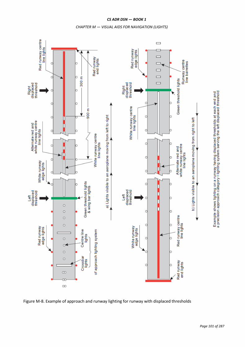
CS ADR DSN — BOOK 1
CHAPTER M — VISUAL AIDS FOR NAVIGATION (LIGHTS)
Page 101 of 287
Figure M-8. Example of approach and runway lighting for runway with displaced thresholds

CS ADR DSN — BOOK 1
CHAPTER M — VISUAL AIDS FOR NAVIGATION (LIGHTS)
Page 102 of 287
CS ADR-DSN.M.690 Runway centre line lights
(a) The safety objective of runway centre line lights is to facilitate safe take-off and landing in reduced visibility conditions.
(b) Applicability:
(1) Runway centre line lights should be provided on a precision approach runway category II or III.
(2) Runway centre line lights should be provided on a runway intended to be used for take-off with an operating minimum below an RVR of the order of 400 m.
(c) Location: Runway centre line lights should be located along the centre line of the runway, except that the lights may be uniformly offset to the same side of the runway centre line by not more than 60 cm where it is not practicable to locate them along the centre line. The lights should be located from the threshold to the end at longitudinal spacing of approximately 15 m. Where the serviceability level of the runway centre line lights specified as maintenance objectives in CS ADR.DSN.S.895 can be demonstrated, and the runway is intended for use in runway visual range conditions of 350 m or greater, the longitudinal spacing may be approximately 30 m.
(d) Characteristics:
(1) Runway centre line lights should be fixed lights showing variable white from the threshold to the point 900 m from the runway end; alternate red and variable white from 900 m to 300 m from the runway end; and red from 300 m to the runway end, except that for runways less than 1 800 m in length, the alternate red and variable white lights should extend from the midpoint of the runway usable for landing to 300 m from the runway end.
(2) Runway centre line lights should be in accordance with the specifications in CS ADR-DSN.U.930 and CS ADR-DSN.U.940.
(e) Centre line guidance for take-off from the beginning of a runway to a displaced threshold should be provided by:
(1) an approach lighting system if its characteristics and intensity settings afford the guidance required during take-off, and it does not dazzle the pilot of an aircraft taking off; or
(2) runway centre line lights; or
(3) barrettes of at least 3 m length, and spaced at uniform intervals of 30 m, as shown in Figure M-8, designed so that their photometric characteristics and intensity setting afford the guidance required during take-off without dazzling the pilot of an aircraft taking off.
Where necessary, provision should be made to extinguish those centre line lights, as prescribed in (2) above or reset the intensity of the approach lighting system or barrettes when the runway is being used for landing. In no case should only the single source runway centre line lights show from the beginning of the runway to a displaced threshold when the runway is being used for landing.
CS ADR-DSN.M.695 Runway touchdown zone lights
(a) Applicability: Touchdown zone lights should be provided in the touchdown zone of a precision approach runway category II or III.
(b) Location and positioning:
(1) Touchdown zone lights should extend from the threshold for a longitudinal distance of 900 m, except that, on runways less than 1 800 m in length, the system should be shortened so that it does not extend beyond the midpoint of the runway.

CS ADR DSN — BOOK 1
CHAPTER M — VISUAL AIDS FOR NAVIGATION (LIGHTS)
Page 103 of 287
(2) The pattern should be formed by pairs of barrettes symmetrically located about the runway centre line. The lateral spacing between the innermost lights of a pair of barrettes should be equal to the lateral spacing selected for the touchdown zone marking. The longitudinal spacing between pairs of barrettes should be either 30 m or 60 m.
(c) Characteristics:
(1) A barrette should be composed of at least three lights with spacing between the lights of not more than 1.5 m.
(2) A barrette should be not less than 3 m or more than 4.5 m in length.
(3) Touchdown zone lights should be fixed unidirectional lights showing variable white.
(4) Touchdown zone lights should be in accordance with the chromaticity and characteristics specifications in CS ADR-DSN.U.930 and CS ADR-DSN.U.940.
CS ADR-DSN.M.700 Rapid exit taxiway indicator lights
CS ADR-DSN.M.705 Stopway lights
(a) Applicability and purpose: Stopway lights should be provided for a stopway intended for use at night.
(b) Location: Stopway lights should be placed along the full length of the stopway and should be in two parallel rows that are equidistant from the centre line and coincident with the rows of the runway edge lights. Stopway lights should also be provided across the end of a stopway on a line at right angles to the stopway axis as near to the end of the stopway as possible and, in any case, not more than 3 m outside the end.
(c) Characteristics:
(1) Stopway lights should be fixed unidirectional lights showing red in the direction of the runway.
(2) Stopway lights should be in accordance with the specifications of CS ADR-DSN.U.940.
CS ADR-DSN.M.710 Taxiway centre line lights
(a) The safety objective of taxiway centre line lights is to provide guidance for the safe taxi of aircraft on a taxiway in reduced visibility conditions and at night.
(b) Applicability:
(1) Taxiway centre line lights should be provided on an exit taxiway, taxiway, de-icing/anti-icing facility, and apron intended for use in runway visual range conditions less than a value of 350 m in such a manner as to provide continuous guidance between the runway centre line and aircraft stands, except that these lights need not be provided where the traffic density is light and taxiway edge lights, and centre line marking provide adequate guidance.
(2) Taxiway centre line lights should be provided on a taxiway intended for use at night in runway visual range conditions of 350 m or greater, and particularly on complex taxiway intersections and exit taxiways, except that these lights need not be provided where the traffic density is light and taxiway edge lights, and centre line marking provide adequate guidance.
(3) Taxiway centre line lights should be provided on an exit taxiway, taxiway, de-icing/anti icing facility, and apron in all visibility conditions where specified as components of an advanced surface movement guidance and control system in such a manner as to provide continuous guidance between the runway centre line and aircraft stands.

CS ADR DSN — BOOK 1
CHAPTER M — VISUAL AIDS FOR NAVIGATION (LIGHTS)
Page 104 of 287
(4) Taxiway centre line lights should be provided on a runway forming part of a standard taxi-route and intended for taxiing in runway visual range conditions less than a value of 350 m, except that these lights need not be provided where the traffic density is light and taxiway edge lights, and centre line marking provide adequate guidance.
(5) Taxiway centre line lights should be provided in all visibility conditions on a runway forming part of a standard taxi-route where specified as components of an advanced surface movement guidance and control system.
(6) Where a runway forming part of a standard taxi route is provided with runway lighting and taxiway lighting, the lighting systems should be interlocked to preclude the possibility of simultaneous operation of both forms of lighting.
(c) Characteristics:
(1) Taxiway centre line lights on a taxiway other than an exit taxiway and on a runway forming part of a standard taxi-route should be fixed lights showing green with beam dimensions such that the light is visible only from aeroplanes on, or in the vicinity of the taxiway.
(2) Taxiway centre line lights on an exit taxiway should be fixed lights. Alternate taxiway centre line lights should show green and yellow from their beginning near the runway centre line to the perimeter of the ILS/MLS critical/sensitive area, or the lower edge of the inner transitional surface, whichever is farthest from the runway; and thereafter all lights should show green, as shown in Figure M-10. The light nearest to the perimeter should always show yellow.
Where aircraft follow the same centre line in both directions, the centre line lights should show green to aircraft approaching the runway.
(3) Taxiway centre line lights should be in accordance with the specifications of CS ADR-DSN.U.940, Figure U-16, U-17, or U-18, for taxiways intended for use in runway visual range conditions of less than a value of 350 m; Figure U-19 or U-20, for other taxiways.
(4) Where higher intensities are required, from an operational point of view, taxiway centre line lights on rapid exit taxiways intended for use in runway visual range conditions less than a value of 350 m should be in accordance with the specifications of CS ADR-DSN.U.940, Figure U-16. The number of levels of brilliancy settings for these lights should be the same as that for the runway centre line lights.
(5) Where taxiway centre line lights are specified as components of an advanced surface movement guidance and control system and where, from an operational point of view, higher intensities are required to maintain ground movements at a certain speed in very low visibilities or in bright daytime conditions, taxiway centre line lights should be in accordance with the specifications of CS ADR-DSN.U.940, Figure U-21, U-22, or U-23.
(6) High intensity centre line lights should only be used in case of an absolute necessity and following a specific study.
(d) Location and positioning:
(1) Taxiway centre line lights should normally be located on the taxiway centre line marking, except that they may be offset by not more than 30 cm where it is not practicable to locate them on the marking, as shown in Figure M-9.
(2) Taxiway centre line lights on taxiways, runways, rapid exit taxiways or on other exit taxiways should be positioned in accordance with CS ADR-DSN.M.715.

CS ADR DSN — BOOK 1
CHAPTER M — VISUAL AIDS FOR NAVIGATION (LIGHTS)
Page 105 of 287
CS ADR-DSN.M.715 Taxiway centre line lights on taxiways, runways, rapid exit taxiways, or on other exit taxiways
(a) The safety objective of taxiway centre line lights is to provide guidance for the safe taxi of aircraft on a taxiway de-icing/anti-icing facility, and apron in reduced visibility conditions and at night
(b) Taxiway centre line lights on taxiways:
(1) Taxiway centre line lights on a straight section of a taxiway should be spaced at longitudinal intervals of not more than 30 m, except that:
(i) intervals less than 30 m should be provided on short straight sections; and
(ii) on a taxiway intended for use in RVR conditions of less than a value of 350 m, the longitudinal spacing should not exceed 15 m.
(2) Taxiway centre line lights on a taxiway curve should continue from the straight portion of the taxiway at a constant distance from the outside edge of the taxiway curve. The lights should be spaced at intervals such that a clear indication of the curve is provided.
(3) On a taxiway intended for use in RVR conditions of less than a value of 350 m, the lights on a curve should not exceed spacing of 15 m, and on a curve of less than 400 m radius the lights should be spaced at intervals of not greater than 7.5 m. This spacing should extend for 60 m before and after the curve.
(c) Taxiway centre line lights on rapid exit taxiways:
(1) Taxiway centre line lights on a rapid exit taxiway should commence at a point at least 60 m before the beginning of the taxiway centre line curve, and continue beyond the end of the curve to a point on the centre line of the taxiway where an aeroplane can be expected to reach normal taxiing speed, as shown in Figure M-10. The lights on that portion parallel to the runway centre line should always be at least 60 cm from any row of runway centre line lights, as shown in Figure M-9.
(2) The lights should be spaced at longitudinal intervals of not more than 15 m. Where runway centre line lights are not provided, a greater interval not exceeding 30 m may be used.
(d) Taxiway centre line lights on other exit taxiways:
(1) Taxiway centre line lights on exit taxiways other than rapid exit taxiways should commence at the point where the taxiway centre line marking begins to curve from the runway centre line, and follow the curved taxiway centre line marking at least to the point where the marking leaves the runway. The first light should be at least 60 cm from any row of runway centre line lights, as shown in Figure M-9, Arrangement of runway threshold and runway end lights.
(2) The lights should be spaced at longitudinal intervals of not more than 7.5 m.
(e) Taxiway centre line lights on runways: Taxiway centre line lights on a runway forming part of a standard taxi-route, and intended for taxiing in runway visual range conditions less than a value of 350 m should be spaced at longitudinal intervals not exceeding 15 m.

CS ADR DSN — BOOK 1
CHAPTER M — VISUAL AIDS FOR NAVIGATION (LIGHTS)
Page 106 of 287
Figure M-9. Offset runway and taxiway centre line lights
(f) Positioning of taxiway centre line lights on taxiway:
(1) The spacing on a particular section of taxiway centre line lighting (straight or curved section) should be such that a clear indication of the taxiway centre line is provided, particularly on a curved section.
(2) Where a taxiway is only intended for use in RVR conditions of 350 m or greater, the spacing of taxiway centre line lights on curves should not exceed the table below:
Curve radius Light spacing
up to 400 m 7.5 m
401 m to 899 m 15 m
900 m or greater 30 m
(g) Taxiway centre line lights on straight sections of taxiways: Larger intervals not exceeding 60 m may be used where, because of the prevailing meteorological conditions, adequate guidance is provided by such spacing.

CS ADR DSN — BOOK 1
CHAPTER M — VISUAL AIDS FOR NAVIGATION (LIGHTS)
Page 107 of 287
Figure M-10. Taxiway lighting

CS ADR DSN — BOOK 1
CHAPTER M — VISUAL AIDS FOR NAVIGATION (LIGHTS)
Page 108 of 287
CS ADR-DSN.M.720 Taxiway edge lights
(a) Applicability:
(1) Taxiway edge lights should be provided at the edges of a runway turn pad, holding bay, de-icing/anti-icing facility, apron, etc. intended for use at night, and on a taxiway not provided with taxiway centre line lights and intended for use at night, except that taxiway edge lights need not be provided where, considering the nature of the operations, adequate guidance can be achieved by surface illumination or other means.
(2) Taxiway edge lights should be provided on a runway forming part of a standard taxi-route and intended for taxiing at night where the runway is not provided with taxiway centre line lights.
(3) Where a runway forming part of a standard taxi route is provided with runway lighting and taxiway lighting, the lighting systems should be interlocked to preclude the possibility of simultaneous operation of both forms of lighting.
(b) Location and positioning:
(1) Taxiway edge lights on a straight section of a taxiway and on a runway forming part of a standard taxi-route should be spaced at uniform longitudinal intervals of not more than 60 m. The lights on a curve should be spaced at intervals less than 60 m so that a clear indication of the curve is provided.
(2) Taxiway edge lights on a holding bay, de-icing/anti-icing facility, apron, etc. should be spaced at uniform longitudinal intervals of not more than 60 m.
(3) Taxiway edge lights on a runway turn pad should be spaced at uniform longitudinal intervals of not more than 30 m.
(4) The lights should be located as near as practicable to the edges of the taxiway, runway turn pad, holding bay, de-icing/anti-icing facility, apron or runway, etc., or outside the edges at a distance of not more than 3 m.
(c) Characteristics:
(1) Taxiway edge lights should be fixed lights showing blue.
(2) The lights should show up to at least 75° above the horizontal and at all angles in azimuth necessary to provide guidance to a pilot taxiing in either direction. At an intersection, exit, or curve the lights should be shielded as far as practicable so that they cannot be seen in angles of azimuth in which they may be confused with other lights.
(3) The intensity of taxiway edge lights should be at least 2 cd from 0° to 6° vertical, and 0.2 cd at any vertical angles between 6° and 75°.
CS ADR-DSN.M.725 Runway turn pad lights
(a) The safety objective of runway turn pad lights is to provide guidance on a runway turn pad intended for use in reduced visibility conditions and at night to enable an aeroplane to complete a safe 180-degree turn, and align with the runway centre line.
(b) Applicability:
(1) Runway turn pad lights should be provided for continuous guidance on a runway turn pad intended for use in runway visual range conditions less than a value of 350 m to enable an aeroplane to complete a 180-degree turn, and align with the runway centre line.
(2) Runway turn pad lights should be provided on a runway turn pad intended for use at night.

CS ADR DSN — BOOK 1
CHAPTER M — VISUAL AIDS FOR NAVIGATION (LIGHTS)
Page 109 of 287
(c) Location:
(1) Runway turn pad lights should normally be located on the runway turn pad marking, except that they should be offset by not more than 30 cm where it is not practicable to locate them on the marking.
(2) Runway turn pad lights on a straight section of the runway turn pad marking should be spaced at longitudinal intervals of not more than 15 m.
(3) Runway turn pad lights on a curved section of the runway turn pad marking should not exceed a spacing of 7.5 m.
(d) Characteristics:
(1) Runway turn pad lights should be unidirectional fixed lights showing green with beam dimensions such that the light is visible only from aeroplanes on or approaching the runway turn pad.
(2) Runway turn pad lights should be in accordance with the specifications of CS ADR-DSN.U.940, Figure U-17 and Figure U-18.
CS ADR-DSN.M.730 Stop bar lights
(a) Applicability:
(1) A stop bar should be provided at every runway-holding position serving a runway when it is intended that the runway should be used in runway visual range conditions less than a value of 550 m, except where:
(i) appropriate aids and procedures are available to assist in preventing inadvertent incursions of aircraft and vehicles onto the runway; or
(ii) operational procedures exist to limit, in runway visual range conditions less than a value of 550 m, the number of:
(A) aircraft on the manoeuvring area to one at a time; and
(B) vehicles on the manoeuvring area to the essential minimum.
(2) A stop bar should be provided at an intermediate holding position when it is desired to supplement markings with lights, and to provide traffic control by visual means.
(b) Location: Stop bars should be located across the taxiway at the point where it is desired that traffic stop.
(c) Characteristics:
(1) Stop bars should consist of lights spaced at intervals of 3 m across the taxiway, showing red in the intended direction(s) of approach to the intersection or runway-holding position.
(2) Stop bars installed at a runway-holding position should be unidirectional, and should show red in the direction of approach to the runway.
(3) Selectively switchable stop bars should be installed in conjunction with at least three taxiway centre line lights (extending for a distance of at least 90 m from the stop bar) in the direction that it is intended for an aircraft to proceed from the stop bar.
(4) The intensity in red light and beam spreads of stop bar lights should be in accordance with the specifications in CS ADR-DSN.U.940, Figures U-16 to U-20.

CS ADR DSN — BOOK 1
CHAPTER M — VISUAL AIDS FOR NAVIGATION (LIGHTS)
Page 110 of 287
(5) Where stop bars are specified as components of an advanced surface movement guidance and control system, and where, from an operational point of view, higher intensities are required to maintain ground movements at a certain speed in very low visibilities or in bright daytime conditions, the intensity in red light and beam spreads of stop bar lights should be in accordance with the specifications in CS ADR-DSN.U.940, Figure U-21, U-22 or U-23.
(6) High-intensity stop bars should only be used in case of an absolute necessity and following a specific study.
(7) Where a wide beam fixture is required, the intensity in red light and beam spreads of stop bar lights should be in accordance with the specifications in CS ADR-DSN.U.940, Figure U-21 or U-23.
(8) The lighting circuit should be designed so that:
(i) stop bars located across entrance taxiways are selectively switchable;
(ii) stop bars located across taxiways intended to be used only as exit taxiways are switchable selectively or in groups;
(iii) when a stop bar is illuminated, any taxiway centre line lights installed beyond the stop bar should be extinguished for a distance of at least 90 m; and
(iv) stop bars should be interlocked with the taxiway centre line lights so that when the centre line lights beyond the stop bar are illuminated, the stop bar is extinguished and vice versa.
CS ADR-DSN.M.735 Intermediate holding position lights
(a) Applicability:
(1) Except where a stop bar has been installed, intermediate holding position lights should be provided at an intermediate holding position intended for use in runway visual range conditions less than a value of 350 m.
(2) Intermediate holding position lights should be provided at an intermediate holding position where there is no need for stop-and-go signals as provided by a stop bar.
(b) Location: Intermediate holding position lights should be located along the intermediate holding position marking at a distance of 0.3 m prior to the marking.
(c) Characteristics: Intermediate holding position lights should consist of three fixed unidirectional lights showing yellow in the direction of approach to the intermediate holding position with a light distribution similar to taxiway centre line lights if provided. The lights should be disposed symmetrically about and at right angle to the taxiway centre line, with individual lights spaced 1.5 m apart.
CS ADR-DSN.M.740 De-icing/anti-icing facility exit lights
(a) Applicability: The purpose of the de-icing/anti-icing facility exit lights is to indicate the exit boundary of a remote de-icing/anti-icing facility adjoining a taxiway.
(b) Location: Where provided, de-icing/anti-icing facility exit lights should be located 0.3 m inward of the intermediate holding position marking displayed at the exit boundary of a remote de-icing/ anti-icing facility.

CS ADR DSN — BOOK 1
CHAPTER M — VISUAL AIDS FOR NAVIGATION (LIGHTS)
Page 111 of 287
(c) Characteristics: Where provided, de-icing/anti-icing facility exit lights should consist of in-pavement fixed unidirectional lights spaced at intervals of 6 m showing yellow in the direction of the approach to the exit boundary with a light distribution similar to taxiway centre line lights (see Figure G-1).
Figure M-11. Example of remote de-icing/anti-icing facility
CS ADR-DSN.M.745 Runway guard lights
(a) The purpose is to warn pilots and drivers of vehicles when they are operating on taxiways, that they are about to enter an active runway. There are two standard configurations of runway guard lights as illustrated in Figure M-12.
(b) Applicability:
(1) Runway guard lights, Configuration A, should be provided at each taxiway/runway intersection associated with a runway intended for use in:
(i) runway visual range conditions less than a value of 550 m regardless of whether or not a stop bar is installed; and
(ii) runway visual range conditions of values between 550 m and 1 200 m where the traffic density is heavy.
(2) Runway guard lights, Configuration A, Configuration B, or both, should be provided at each taxiway/runway intersection where enhanced conspicuity of the taxiway/runway intersection is needed, such as on a wide-throat taxiway, except that Configuration B should not be collocated with a stop bar.
(c) Location:
(1) Runway guard lights, Configuration A should be located at each side of the taxiway and at the same distance as the runway-holding position marking.
(2) Runway guard lights, Configuration B, should be located across the taxiway and at the same distance as the runway-holding position marking.
(d) Characteristics:
(1) Runway guard lights, Configuration A, should consist of two pairs of yellow lights.
Minimum separation distance
(see CS-ADR.DSN.G.400 (d)
and Table D-1, column 11)

CS ADR DSN — BOOK 1
CHAPTER M — VISUAL AIDS FOR NAVIGATION (LIGHTS)
Page 112 of 287
(2) Runway guard lights, Configuration B, should consist of yellow lights spaced at intervals of 3 m across the taxiway.
(3) The light beam should be unidirectional and aligned so as to be visible to the pilot of an aeroplane taxiing to the holding position.
(4) The intensity in yellow light and beam spreads of lights of Configuration A should be in accordance with the specifications in CS ADR-DSN.U.940, Figure U-27.
(5) Where runway guard lights are intended for use during the day, the intensity in yellow light and beam spreads of lights of Configuration A should be in accordance with the specifications in CS ADR-DSN.U.940, Figure U-28.
(6) Where runway guard lights are specified as components of an advanced surface movement guidance and control system where higher light intensities are required, the intensity in yellow light and beam spreads of lights of Configuration A should be in accordance with the specifications in CS ADR-DSN.U.940, Figure U-28.
(7) The intensity in yellow light and beam spreads of lights of Configuration B should be in accordance with the specifications in CS ADR-DSN.U.940, Figure U-28.
(8) Where runway guard lights are intended for use during the day, the intensity in yellow light and beam spreads of lights of Configuration B should be in accordance with the specifications in CS ADR-DSN.U.940, Figure U-24.
(9) Where runway guard lights are specified as components of an advanced surface movement guidance and control system where higher light intensities are required, the intensity in yellow light and beam spreads of lights of Configuration B should be in accordance with the specifications in CS ADR-DSN.U.940, Figure U-24.
(10) The lights in each unit of Configuration A should be illuminated alternately.
(11) For Configuration B, adjacent lights should be alternately illuminated and alternative lights should be illuminated in unison.
(12) The lights should be illuminated between 30 and 60 cycles per minute and the light suppression and illumination periods should be equal and opposite in each light.

CS ADR DSN — BOOK 1
CHAPTER M — VISUAL AIDS FOR NAVIGATION (LIGHTS)
Page 113 of 287
Figure M-12. Runway guard lights

CS ADR DSN — BOOK 1
CHAPTER M — VISUAL AIDS FOR NAVIGATION (LIGHTS)
Page 114 of 287
SECTION 4 — APRON LIGHTING
CS ADR-DSN.M.750 Apron floodlighting
(a) The purpose of apron floodlighting is to facilitate safe operations on an apron, on a de-icing/anti-icing facility, and on a designated isolated aircraft parking position intended to be used in reduced visibility conditions and at night.
(b) Applicability: Apron floodlighting should be provided on an apron, as necessary on a de-icing/anti-icing facility, and on a designated isolated aircraft parking position intended to be used at night. Aprons primarily used for recreational flying need not be illuminated.
(c) Location: Apron floodlights should be located so as to provide adequate illumination on all apron service areas, with a minimum of glare to pilots of aircraft in flight and on the ground, aerodrome and apron controllers, and personnel on the apron. The arrangement and aiming of floodlights should be such that an aircraft stand receives light from two or more directions to minimise shadows.
(d) Characteristics:
(1) The spectral distribution of apron floodlights should be such that the colours used for aircraft marking connected with routine servicing, and for surface and obstacle marking, can be correctly identified.
(2) The average illuminance should be at least the following:
(i) Aircraft stand:
(A) horizontal illuminance — 20 lux with a uniformity ratio (average to minimum) of not more than 4 to 1; and
(B) vertical illuminance — 20 lux at a height of 2 m above the apron in relevant directions.
(ii) Other apron areas: horizontal illuminance — 50 % of the average illuminance on the aircraft stands with a uniformity ratio (average to minimum) of not more than 4 to 1.
CS ADR-DSN.M.755 Visual docking guidance system
(a) Applicability: A visual docking guidance system should be provided when it is intended to indicate, by a visual aid, the precise positioning of an aircraft on an aircraft stand and other alternative means, such as marshallers, are not practicable.
(b) Characteristics:
(1) The system should provide both azimuth and stopping guidance.
(2) The azimuth guidance unit and the stopping position indicator should be adequate for use in all weather, visibility, background lighting, and pavement conditions for which the system is intended both by day and night but should not dazzle the pilot.
(3) The azimuth guidance unit and the stopping position indicator should be of a design such that:
(i) a clear indication of malfunction of either or both is available to the pilot; and
(ii) they can be turned off.

CS ADR DSN — BOOK 1
CHAPTER M — VISUAL AIDS FOR NAVIGATION (LIGHTS)
Page 115 of 287
(4) The accuracy of the system should be adequate for the type of loading bridge and fixed aircraft servicing installations with which it is to be used.
(5) The system should be usable by all types of aircraft for which the aircraft stand is intended, preferably without selective operation.
(6) If selective operation is required to prepare the system for use by a particular type of aircraft, then the system should provide an identification of the selected aircraft type to both the pilot and the system operator as a means of ensuring that the system has been set properly.
(c) Location:
(1) The azimuth guidance unit and the stopping position indicator should be located in such a way that there is continuity of guidance between the aircraft stand markings, the aircraft stand manoeuvring guidance lights if present, and the visual docking guidance system.
(2) The azimuth guidance unit should be located on or close to the extension of the stand centre
line ahead of the aircraft so that its signals are visible from the cockpit of an aircraft
throughout the docking manoeuvre, and aligned for use at least by the pilot occupying the left
seat, although it is preferable for it to be aligned for use by the pilots occupying both the left
and right seats.
(3) The azimuth guidance unit and the stopping position indicator should be positioned as prescribed below.
(i) The azimuth guidance unit should provide unambiguous left/right guidance which enables the pilot to acquire and maintain the lead-in line without over-controlling.
(ii) When azimuth guidance is indicated by colour change, green should be used to identify the centre line and red for deviations from the centre line.
(iii) The stopping position indicator should be located in conjunction with, or sufficiently close to, the azimuth guidance unit so that a pilot can observe both the azimuth and stop signals without turning the head.
(iv) The stopping position indicator should be usable at least by the pilot occupying the left seat, although it is preferable for it to be usable by the pilots occupying both the left and right seats.
(v) The stopping position information provided by the indicator for a particular aircraft type should account for the anticipated range of variations in pilot eye height and/or viewing angle.
(vi) The stopping position indicator should show the stopping position for the aircraft for which guidance is being provided and should provide closing rate information to enable the pilot to gradually decelerate the aircraft to a full stop at the intended stopping position.
(vii) The stopping position indicator should provide closing rate information over a distance of at least 10 m.
(viii) When stopping guidance is indicated by colour change, green should be used to show that the aircraft can proceed and red to show that the stop point has been reached ,except that for a short distance prior to the stop point a third colour may be used to warn that the stopping point is close.

CS ADR DSN — BOOK 1
CHAPTER M — VISUAL AIDS FOR NAVIGATION (LIGHTS)
Page 116 of 287
CS ADR-DSN.M.760 Advanced visual docking guidance system
(a) Application:
(1) Advanced visual docking guidance system should be provided where it is operationally desirable to confirm the correct aircraft type for which guidance is being provided, and/or to indicate the stand centre line in use, where more than one is provided for.
(2) The Advanced visual docking guidance system should be suitable for use by all types of aircraft for which the aircraft stand is intended.
(3) The Advanced visual docking guidance system should only be used in conditions in which its operational performance is specified.
(4) The docking guidance information provided by an advanced visual docking guidance system should not conflict with that provided by a conventional visual docking guidance system on an aircraft stand if both types are provided, and are in operational use. A method of indicating that the system is not in operational use or unserviceable should be provided.
(5) Location: The Advanced visual docking guidance system should be located such that unobstructed and unambiguous guidance is provided to the person responsible for, and persons assisting, the docking of the aircraft throughout the docking manoeuvre.
(b) Characteristics:
(1) The Advanced visual docking guidance system should provide, at minimum, the following guidance information at the appropriate stage of the docking manoeuvre:
(i) an emergency stop indication;
(ii) the aircraft type and model for which the guidance is provided;
(iii) an indication of the lateral displacement of the aircraft relative to the stand centre line;
(iv) the direction of azimuth correction needed to correct a displacement from the stand centre line;
(v) an indication of the distance to the stop position;
(vi) an indication when the aircraft has reached the correct stopping position; and
(vii) a warning indication if the aircraft goes beyond the appropriate stop position.
(2) The Advanced visual docking guidance system should be capable of providing docking guidance information for all aircraft taxi speeds encountered during the docking manoeuvre.
(3) The time taken from the determination of the lateral displacement to its display should not result in a deviation of the aircraft when operated in normal conditions, from the stand centre line greater than 1 m.
(4) The information on displacement of the aircraft relative to the stand centre line and distance to the stopping position, when displayed, should be provided with the accuracy specified in Table M-3. Symbols and graphics used to depict guidance information should be intuitively representative of the type of information provided.
(i) Information on the lateral displacement of the aircraft relative to the stand centre line should be provided at least 25 m prior to the stop position.
(ii) Continuous closure distance and closure rate should be provided from at least 15 m prior to the stop position.

CS ADR DSN — BOOK 1
CHAPTER M — VISUAL AIDS FOR NAVIGATION (LIGHTS)
Page 117 of 287
(iii) Where provided, closure distance displayed in numerals should be provided in metre integers to the stop position and displayed to 1 decimal place at least 3 m prior to the stop position.
(iv) Throughout the docking manoeuvre, an appropriate means should be provided on the Advanced visual docking guidance system to indicate the need to bring the aircraft to an immediate halt. In such an event which includes a failure of the system, no other information should be displayed.
(v) Provision to initiate an immediate halt to the docking procedure should be made available to personnel responsible for the operational safety of the stand.
(vi) The word ‘STOP’ in red characters should be displayed when an immediate cessation of the docking manoeuvre is required.
Guidance information
Maximum deviation at stop
position (stop area)
Maximum deviation at 9 m
from stop position
Maximum deviation at 15 m
from stop position
Maximum deviation at 25 m from stop position
Azimuth ±250 mm ±340 mm ±400 mm ±500 mm
Distance ±500 mm ±1000 mm ±1300 mm Not specified
Table M-3. A-VDGS recommended displacement accuracy
CS ADR-DSN.M.765 Aircraft stand manoeuvring guidance lights
(a) Applicability: Aircraft stand manoeuvring guidance lights should be provided to facilitate the positioning of an aircraft on an aircraft stand on a paved apron, or on a de-icing/anti-icing facility intended for use in poor visibility conditions unless adequate guidance is provided by other means.
(b) Location: Aircraft stand manoeuvring guidance lights should be collocated with the aircraft stand markings.
(c) Characteristics:
(1) Aircraft stand manoeuvring guidance lights, other than those indicating a stop position, should be fixed yellow lights, visible throughout the segments within which they are intended to provide guidance.
(2) The lights used to delineate lead-in, turning, and lead-out lines should be spaced at intervals of not more than 7.5 m on curves and 15 m on straight sections.
(3) The lights indicating a stop position should be fixed, unidirectional lights showing red.
(4) The intensity of the lights should be adequate for the condition of visibility and ambient light in which the use of the aircraft stand is intended.
(5) The lighting circuit should be designed so that the lights may be switched on to indicate that an aircraft stand is to be used, and switched off to indicate that it is not to be used.

CS ADR DSN — BOOK 1
CHAPTER M — VISUAL AIDS FOR NAVIGATION (LIGHTS)
Page 118 of 287
CS ADR-DSN.M.770 Road-holding position light
(a) Applicability: A road-holding position light should be provided at each road-holding position serving a runway when it is intended that the runway should be used in runway visual range conditions less than a value of 550 m.
(b) Location: A road-holding position light should be located adjacent to the holding position marking 1.5 m (±0.5 m) from one edge of the road, i.e. left or right as appropriate to the local road traffic regulations.
(c) Characteristics:
(1) The road-holding position light should comprise:
(i) a controllable red (stop)/green (go) traffic light; or
(ii) a flashing-red light
(2) Provisions for control of the lights in (1) (i) should be installed in the positions for the air traffic services.
(3) The road-holding position light beam should be unidirectional and aligned so as to be visible to the driver of a vehicle approaching the holding position.
(4) The intensity of the light beam should be adequate for the conditions of visibility and ambient light in which the use of the holding position is intended but should not dazzle the driver.
(5) The flash frequency of the flashing red light should be between 30 and 60 flashes per minute.
CS-ADR-DSN — BOOK 1
CHAPTER N — VISUAL AIDS FOR NAVIGATION (SIGNS)
Page 119 of 287
CHAPTER N — VISUAL AIDS FOR NAVIGATION (SIGNS)
CS ADR-DSN.N.775 General
(a) Signs should be either fixed message signs or variable message signs.
(b) Application:
(1) Signs should be provided to convey a mandatory instruction, information on a specific location, or destination on a movement area or to provide other information.
(2) A variable message sign should be provided where:
(i) the instruction or information displayed on the sign is relevant only during a certain period of time; and/or
(ii) there is a need for variable predetermined information to be displayed.
(c) Characteristics:
(1) Signs should be frangible. Those located near a runway or taxiway should be sufficiently low to preserve clearance for propellers and the engine pods of jet aircraft. The installed height of the sign should not exceed the dimension shown in the appropriate column of Table N-1.
(2) Signs should be rectangular, as shown in Figures N-4 and N-6 with the longer side horizontal.
(3) The only signs on the movement area utilising red should be mandatory instruction signs.
(4) The inscriptions on a sign should be in accordance with the provisions of Figures N-2A to N-2H and N-3.
(5) Signs should be illuminated when intended for use:
(i) in runway visual range conditions less than a value of 800 m; or
(ii) at night in association with instrument runways; or
(iii) at night in association with non-instrument runways where the code number is 3 or 4.
(6) Signs should be retroreflective and/or illuminated when intended for use at night in association with non-instrument runways where the code number is 1 or 2.
(7) Where variable pre-determined information is required, a variable sign should be provided.
(i) A variable message sign should show a blank face when not in use.
(ii) In case of failure, a variable message sign should not provide information that could lead to unsafe action from a pilot or a vehicle driver.
(iii) The time interval to change from one message to another on a variable message sign should be as short as practicable and should not exceed 5 seconds.
Sign height (mm) Perpendicular distance Perpendicular distance

CS-ADR-DSN — BOOK 1
CHAPTER N — VISUAL AIDS FOR NAVIGATION (SIGNS)
Page 120 of 287
Runway code
number
Legend Face (min) Installed (max)
from defined taxiway pavement edge to near
side of sign
from defined runway pavement edge to near
side of sign
1 or 2 200 400 700 5–11 m 3–10 m
1 or 2 300 600 900 5–11 m 3–10 m
3 or 4 300 600 900 11–21 m 8–15 m
3 or 4 400 800 1 100 11–21 m 8–15 m
Table N-1. Location distances for taxiing guidance signs including runway exit signs
(8) Inscription heights should conform to the Table N-2.
Table N-2. Minimum character height
(9) Where a taxiway location sign is installed in conjunction with a runway designation sign (see CS ADR-DSN.N.785(b)(9)), the character size should be that specified for mandatory instruction signs.
(i) Arrow dimensions should be as follows:
Legend height Stroke
200 mm 32 mm
300 mm 48 mm
400 mm 64 mm
(ii) Stroke width for single letter should be as follows:
Legend height Stroke
200 mm 32 mm
300 mm 48 mm
400 mm 64 mm

CS-ADR-DSN — BOOK 1
CHAPTER N — VISUAL AIDS FOR NAVIGATION (SIGNS)
Page 121 of 287
(10) Sign luminance should be as follows:
(i) Where operations are conducted in runway visual range conditions less than a value of
800 m, average sign luminance should be at least:
Red 30 cd/m2
Yellow 150 cd/m2
White 300 cd/m2
(ii) Where operations are conducted in accordance with CS ADR-DSN.N.775(c)(5)(ii) and (c)(6), average sign luminance should be at least:
Red 10 cd/m2
Yellow 50 cd/m2
White 100 cd/m2
(iii) In runway visual range conditions less than a value of 400 m, there should be some
degradation in the performance of signs.
(11) The luminance ratio between red and white elements of a mandatory instruction sign should
be between 1:5 and 1:10.
(12) The average luminance of the sign is calculated by establishing grid points as shown in Figure
N-1, and using the luminance values measured at all grid points located within the rectangle
representing the sign.
(13) The average value is the arithmetic average of the luminance values measured at all
considered grid points.
(14) The ratio between luminance values of adjacent grid points should not exceed 1.5:1. For areas
on the sign face where the grid spacing is 7.5 cm, the ratio between luminance values of
adjacent grid points should not exceed 1.25:1. The ratio between the maximum and minimum
luminance value over the whole sign face should not exceed 5:1.
(15) The forms of characters, i.e. letters, numbers, arrows, and symbols should conform to those
shown in Figures N-2A to N-2H. The width of characters and the space between individual
characters should be determined as indicated in Table N-3.
(16) The face height of signs should be as follows:
Legend height Face height (min)
200 mm 400 mm
300 mm 600 mm
400 mm 800 mm
(17) The face width of signs should be determined using Figure N-3 except that, where a mandatory
instruction sign is provided on one side of a taxiway only, the face width should not be less
than:
(i) 1.94 m where the code number is 3 or 4; and

CS-ADR-DSN — BOOK 1
CHAPTER N — VISUAL AIDS FOR NAVIGATION (SIGNS)
Page 122 of 287
(ii) 1.46 m where the code number is 1 or 2.
(18) Borders:
(i) The black vertical delineator between adjacent direction signs should have a width of
approximately 0.7 of the stroke width.
(ii) The yellow border on a stand-alone location sign should be approximately 0.5 stroke
width.
(19) The colours of signs should be in accordance with the appropriate specifications in
CHAPTER U — Colours for aeronautical ground lights, markings, signs and panels.
(20) If instruction or information during a certain period of time, and/or there is a need to display variable pre-determined information, a variable information sign should be provided.
(i) A variable message sign should show a blank face when not in use.
(ii) In case of failure, a variable message sign should not provide information that could lead to unsafe action from a pilot or a vehicle driver.
(iii) The time interval to change from one message to another on a variable message sign should be as short as practicable and should not exceed 5 seconds.
If the runway threshold is displaced from the extremity of the runway, a sign showing the designation of the runway may be provided for aeroplanes taking off.

CS-ADR-DSN — BOOK 1
CHAPTER N — VISUAL AIDS FOR NAVIGATION (SIGNS)
Page 123 of 287
Note 1.— The average luminance of a sign is calculated by establishing grid points on a sign face showing typical inscriptions and a background of the appropriate colour (red for mandatory instruction signs and yellow for direction and destination signs) as follows:
(a) Starting at the top left corner of the sign face, establish a reference grid point at 7.5 cm from the left edge and the top of the sign face.
(b) Create a grid of 15 cm spacing horizontally and vertically from the reference grid point. Grid points within 7.5 cm of the edge of the sign face should be excluded.
(c) Where the last point in a row/column of grid points is located between 22.5 cm and 15 cm from the edge of the sign face (but not inclusive), an additional point should be added 7.5 cm from this point.
(d) Where a grid point falls on the boundary of a character and the background, the grid point should be slightly shifted to be completely outside the character.
Note 2.— Additional grid points may be required to ensure that each character includes at least five evenly spaced grid points.
Note 3.— Where one unit includes two types of signs, a separate grid should be established for each type.
Figure N-1. Grid points for calculating average luminance of a sign

CS-ADR-DSN — BOOK 1
CHAPTER N — VISUAL AIDS FOR NAVIGATION (SIGNS)
Page 124 of 287
Figure N-2A. Forms of characters for signs

CS-ADR-DSN — BOOK 1
CHAPTER N — VISUAL AIDS FOR NAVIGATION (SIGNS)
Page 125 of 287
Figure N-2B. Forms of characters for signs

CS-ADR-DSN — BOOK 1
CHAPTER N — VISUAL AIDS FOR NAVIGATION (SIGNS)
Page 126 of 287
Figure N-2C. Forms of characters for signs

CS-ADR-DSN — BOOK 1
CHAPTER N — VISUAL AIDS FOR NAVIGATION (SIGNS)
Page 127 of 287
Figure N-2D. Forms of characters for signs

CS-ADR-DSN — BOOK 1
CHAPTER N — VISUAL AIDS FOR NAVIGATION (SIGNS)
Page 128 of 287
Figure N-2E. Forms of characters for signs

CS-ADR-DSN — BOOK 1
CHAPTER N — VISUAL AIDS FOR NAVIGATION (SIGNS)
Page 129 of 287
Figure N-2F. Runway vacated sign
Figure N-2G. No entry sign

CS-ADR-DSN — BOOK 1
CHAPTER N — VISUAL AIDS FOR NAVIGATION (SIGNS)
Page 130 of 287
Figure N-2H. Forms of characters for signs
Figure N-3. Sign dimensions
Note 1. — The arrow stroke width, diameter of the dot, and both
width and length of the dash should be proportioned to the character
stroke widths.
Note 2. — The dimensions of the arrow should remain constant for a
particular sign size, regardless of orientation.

CS-ADR-DSN — BOOK 1
CHAPTER N — VISUAL AIDS FOR NAVIGATION (SIGNS)
Page 131 of 287
Table N-3. Letter and numeral width and space between letters or numerals

CS-ADR-DSN — BOOK 1
CHAPTER N — VISUAL AIDS FOR NAVIGATION (SIGNS)
Page 132 of 287
CS ADR-DSN.N.780 Mandatory instruction signs
(a) Application:
(1) A mandatory instruction sign should be provided to identify a location beyond which an aircraft taxiing or vehicle should not proceed unless authorised by the aerodrome control tower.
(2) Mandatory instruction signs should include runway designation signs, category I, II, or III holding position signs, runway-holding position signs, road-holding position signs, and NO ENTRY signs.
(3) A pattern ‘A’ runway-holding position marking should be supplemented at a taxiway/runway intersection or a runway/runway intersection with a runway designation sign.
(4) A pattern ‘B’ runway-holding position marking should be supplemented with a category I, II, or III holding position sign.
(5) A pattern ‘A’ runway-holding position marking at a runway-holding position should be supplemented with a runway-holding position sign.
(6) A runway designation sign at a taxiway/runway intersection should be supplemented with a location sign in the outboard (farthest from the taxiway) position as appropriate.
(7) A road-holding position sign should be provided at all road entrances to a runway and may also be provided at road entrances to taxiways.
(8) A NO ENTRY sign should be provided when entry into an area is prohibited.
(b) Location:
(1) A runway designation sign at a taxiway/runway intersection or a runway/runway intersection should be located on each side of the runway-holding position marking facing the direction of approach to the runway.
(2) A category I, II, or III holding position sign should be located on each side of the runway-holding position marking facing the direction of the approach to the critical area.
(3) A NO ENTRY sign should be located at the beginning of the area to which entrance is prohibited on each side of the taxiway as viewed by the pilot.
(4) A runway-holding position sign should be located on each side of the runway-holding position facing the approach to the obstacle limitation surface or ILS/MLS critical/sensitive area as appropriate.
(c) Characteristics:
(1) A mandatory instruction sign should consist of an inscription in white on a red background. Where, owing to environmental or other factors, the conspicuity of the inscription on a mandatory instruction sign needs to be enhanced, the outside edge of the white inscription should be supplemented by a black outline measuring 10 mm in width for runway code numbers 1 and 2, and 20 mm in width for runway code numbers 3 and 4.
(2) The inscription on a runway designation sign should consist of the runway designations of the intersecting runway properly oriented with respect to the viewing position of the sign, except that a runway designation sign installed in the vicinity of a runway extremity may show the runway designation of the concerned runway extremity only.
(3) The inscription on a category I, II, III, or joint II/III holding position sign should consist of the runway designator followed by CAT I, CAT II, CAT III, or CAT II/III as appropriate.

CS-ADR-DSN — BOOK 1
CHAPTER N — VISUAL AIDS FOR NAVIGATION (SIGNS)
Page 133 of 287
(4) The inscription on a NO ENTRY sign should be in accordance with Figure N-4.
(5) The inscription on a runway-holding position sign at a runway-holding position should consist of the taxiway designation and a number.
(d) Where appropriate, the following inscriptions/symbol should be used:
Inscription/Symbol Use
Runway designation of runway
extremity
To indicate a runway holding position at a runway extremity
or
Runway designation of both extremities
of a runway
To indicate a runway holding position located at other taxiway/runway intersections or runway/runway intersections
25 CAT I (Example) To indicate a category I runway-holding position at the threshold of runway 25
25 CAT II (Example) To indicate a category II runway-holding position at the threshold of runway 25
25 CAT III (Example) To indicate a category III runway-holding position at the threshold of runway 25
25 CAT II/III (Example) To indicate a joint category II/III runway holding position at the threshold of runway 25
NO ENTRY symbol To indicate that entry to an area is prohibited
B2 (Example) To indicate a runway holding position established in accordance with the requirements for physical characteristics

CS-ADR-DSN — BOOK 1
CHAPTER N — VISUAL AIDS FOR NAVIGATION (SIGNS)
Page 134 of 287
Figure N-4. Mandatory instruction signs
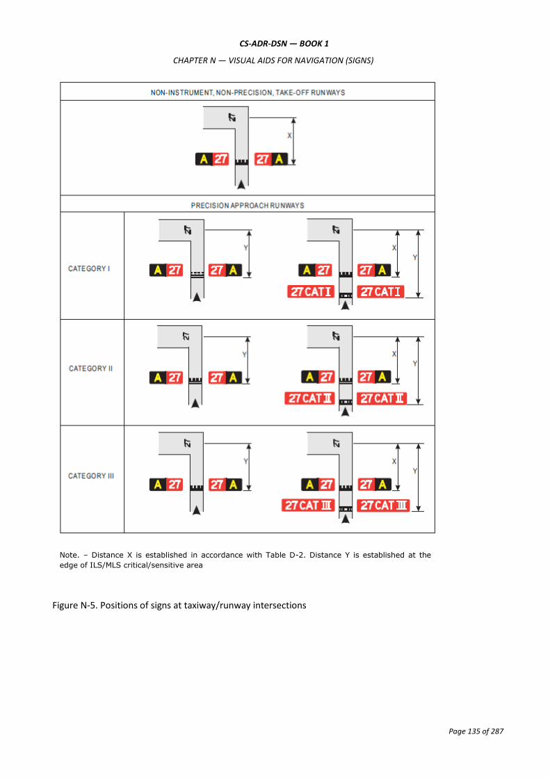
CS-ADR-DSN — BOOK 1
CHAPTER N — VISUAL AIDS FOR NAVIGATION (SIGNS)
Page 135 of 287
Figure N-5. Positions of signs at taxiway/runway intersections
Note. – Distance X is established in accordance with Table D-2. Distance Y is established at the
edge of ILS/MLS critical/sensitive area
CS-ADR-DSN — BOOK 1
CHAPTER N — VISUAL AIDS FOR NAVIGATION (SIGNS)
Page 136 of 287
CS ADR-DSN.N.785 Information signs
(a) Application:
(1) An information sign should be provided where there is an operational need to identify by a sign, a specific location, or routing (direction or destination) information.
(2) Information signs should include: direction signs, location signs, destination signs, runway exit signs, runway vacated signs, and intersection take-off signs.
(3) A runway exit sign should be provided where there is an operational need to identify a runway exit.
(4) A runway vacated sign should be provided where the exit taxiway is not provided with taxiway centre line lights and there is a need to indicate to a pilot leaving a runway the perimeter of the ILS/MLS critical/sensitive area, or the lower edge of the inner transitional surface whichever is farther from the runway centre line.
(5) At runways where intersection take-offs are conducted, an intersection take-off sign should be provided to indicate the remaining take-off run available (TORA) for such take-offs.
(6) Where necessary, a destination sign should be provided to indicate the direction to a specific destination on the aerodrome, such as cargo area, general aviation, etc.
(7) A combined location and direction sign should be provided when it is intended to indicate routing information prior to a taxiway intersection.
(8) A direction sign should be provided when there is an operational need to identify the designation and direction of taxiways at an intersection.
(9) A location sign should be provided at an intermediate holding position.
(10) A location sign should be provided in conjunction with a runway designation sign except at a runway/runway intersection.
(11) A location sign should be provided in conjunction with a direction sign, except that it may be omitted where an safety assessment indicates that it is not needed.
(12) Where necessary, a location sign should be provided to identify taxiways exiting an apron or taxiways beyond an intersection.
(13) Where a taxiway ends at an intersection such as a ‘T’ and it is necessary to identify this, a barricade, direction sign, and/or other appropriate visual aid should be used.
(b) Location:
(1) Except as specified in (3), information signs should wherever practicable, be located on the left-hand side of the taxiway in accordance with Table N-1.
(2) At a taxiway intersection, information signs should be located prior to the intersection and in line with the taxiway intersection marking. Where there is no taxiway intersection marking, the signs should be installed at least 60 m from the centre line of the intersecting taxiway where the code number is 3 or 4, and at least 40 m where the code number is 1 or 2.
(3) A runway exit sign should be located on the same side of the runway as the exit is located (i.e. left or right), and positioned in accordance with Table N-1.
(4) A runway exit sign should be located prior to the runway exit point in line with a position at least 60 m prior to the point of tangency where the code number is 3 or 4, and at least 30 m where the code number is 1 or 2.

CS-ADR-DSN — BOOK 1
CHAPTER N — VISUAL AIDS FOR NAVIGATION (SIGNS)
Page 137 of 287
(5) A runway vacated sign should be located at least on one side of the taxiway. The distance between the sign and the centre line of a runway should be not less than the greater of the following:
(i) the distance between the centre line of the runway and the perimeter of the ILS/MLS critical/sensitive area; or
(ii) the distance between the centre line of the runway and the lower edge of the inner transitional surface.
(6) Where provided in conjunction with a runway vacated sign, the taxiway location sign should be positioned outboard of the runway vacated sign.
(7) An intersection take-off sign should be located at the left-hand side of the entry taxiway. The distance between the sign and the centre line of the runway should be not less than 60 m where the code number is 3 or 4 and not less than 45 m where the code number is 1 or 2.
(8) A taxiway location sign installed in conjunction with a runway designation sign should be positioned outboard of the runway designation sign.
(9) A destination sign should not normally be collocated with a location or direction sign.
(10) An information sign other than a location sign should not be collocated with a mandatory instruction sign.
(c) Characteristics:
(1) An information sign other than a location sign should consist of an inscription in black on a yellow background.
(2) A location sign should consist of an inscription in yellow on a black background and where it is a stand-alone sign, should have a yellow border.
(3) The inscription on a runway exit sign should consist of the designator of the exit taxiway and an arrow indicating the direction to follow.
(4) The inscription on a runway vacated sign should depict the pattern A runway-holding position marking as shown in Figure N-6.
(5) The inscription on an intersection take-off sign should consist of a numerical message indicating the remaining take-off run available in metres, plus an arrow, appropriately located and oriented, indicating the direction of the take-off as shown in Figure N-6.
(6) The inscription on a destination sign should comprise an alpha, alphanumerical or numerical message identifying the destination, plus an arrow indicating the direction to proceed as shown in Figure N-6.
(7) The inscription on a direction sign should comprise an alpha or alphanumerical message identifying the taxiway(s), plus an arrow or arrows appropriately oriented as shown in Figure N-6.
(8) The inscription on a location sign should comprise the designation of the location taxiway, runway, or other pavement the aircraft is on or is entering, and should not contain arrows.
(9) Where it is necessary to identify each of a series of intermediate holding positions on the same taxiway, the location sign should consist of the taxiway designation and a progressive number.
(10) Where a location sign and direction signs are used in combination:
(i) all direction signs related to left turns should be placed on the left side of the location sign and all direction signs related to right turns should be placed on the right side of the

CS-ADR-DSN — BOOK 1
CHAPTER N — VISUAL AIDS FOR NAVIGATION (SIGNS)
Page 138 of 287
location sign, except that where the junction consists of one intersecting taxiway, the location sign may alternatively be placed on the left hand side;
(ii) the direction signs should be placed such that the direction of the arrows departs increasingly from the vertical with increasing deviation of the corresponding taxiway;
(iii) an appropriate direction sign should be placed next to the location sign where the direction of the location taxiway changes significantly beyond the intersection; and
(iv) adjacent direction signs should be delineated by a vertical black line as shown in Figure N-6.
(11) A taxiway should be identified by a designator comprising a letter, letters, or a combination of a letter or letters followed by a number.
(12) When designating taxiways, the use of the letters I, O, or X, and the use of words such as ‘inner’ and ‘outer’ should be avoided wherever possible, to avoid confusion with the numerals 1, 0, and closed marking.
(13) The use of numbers alone on the manoeuvring area should be reserved for the designation of runways, or to indicate the location of aircraft stands.

CS-ADR-DSN — BOOK 1
CHAPTER N — VISUAL AIDS FOR NAVIGATION (SIGNS)
Page 139 of 287
Figure N-6. Information signs

CS-ADR-DSN — BOOK 1
CHAPTER N — VISUAL AIDS FOR NAVIGATION (SIGNS)
Page 140 of 287
CS ADR-DSN.N.790 VOR aerodrome checkpoint sign
When a VOR aerodrome check-point is established, it should be indicated by a VOR aerodrome check-point marking and sign.
(a) Location: A VOR aerodrome check-point sign should be located as near as possible to the check-point and so that the inscriptions are visible from the cockpit of an aircraft properly positioned on the VOR aerodrome check-point marking.
(b) Characteristics:
(1) A VOR aerodrome check-point sign should consist of an inscription in black on a yellow background.
(2) The inscriptions on a VOR check-point sign should be in accordance with one of the alternatives shown in Figure N-7 in which:
VOR is an abbreviation identifying this as a VOR check-point;
116.3 is an example of the radio frequency of the VOR concerned;
147° is an example of the VOR bearing, to the nearest degree, which should be indicated at the VOR check-point; and
4.3 NM is an example of the distance in nautical miles to a DME collocated with the VOR concerned.
Figure N-7. VOR aerodrome check-point sign

CS-ADR-DSN — BOOK 1
CHAPTER N — VISUAL AIDS FOR NAVIGATION (SIGNS)
Page 141 of 287
CS ADR-DSN.N.795 Aircraft stand identification signs
(a) Application: An aircraft stand identification marking should be supplemented with an aircraft stand identification sign where feasible.
(b) Location: An aircraft stand identification sign should be located so as to be clearly visible from the cockpit of an aircraft prior to entering the aircraft stand.
(c) Characteristics: An aircraft stand identification sign should consist of an inscription in black on a yellow background.
CS ADR-DSN.N.800 Road-holding position sign
(a) Application: A road-holding position sign should be provided at all road entrances to a runway.
(b) Location: The road-holding position sign should be located 1.5 m from one edge of the road (left or right as appropriate to the local road traffic regulations) at the holding position.
(c) Where a road intersects a taxiway, a suitable sign may be located adjacent to the roadway/taxiway intersection marking 1.5 m from one edge of the road, i.e. left or right as appropriate to the local road traffic regulations.
(d) Characteristics:
(1) A road-holding position sign at an intersection of a road with a runway should consist of an inscription in white on a red background.
(2) The inscription on a road-holding position sign should be in the national language, be in conformity with the local road traffic regulations, and include the following:
(i) a requirement to stop; and
(ii) where appropriate:
(A) a requirement to obtain ATC clearance; and
(B) location designator.
(3) A road-holding position sign intended for night use should be retroreflective or illuminated.
(4) A road-holding position sign at the intersection of a road with a taxiway should be in accordance with the local road traffic regulations for a yield right of way sign or a stop sign.

CS-ADR-DSN — BOOK 1
CHAPTER P — VISUAL AIDS FOR NAVIGATION (MARKERS)
Page 142 of 287
CHAPTER P — VISUAL AIDS FOR NAVIGATION (MARKERS)
CS ADR-DSN.P.805 General
Markers should be frangible. Those located near a runway or taxiway should be sufficiently low to preserve clearance for propellers, and for the engine pods of jet aircraft.
CS ADR-DSN.P.810 Unpaved runway edge markers
(a) Applicability: Markers should be provided when the extent of an unpaved runway is not clearly indicated by the appearance of its surface compared with that of the surrounding ground.
(b) Characteristics:
(1) Where runway lights are provided, the markers should be incorporated in the light fixtures. Where there are no lights, markers of flat rectangular or conical shape should be placed so as to delimit the runway clearly.
(2) The flat rectangular markers should have a minimum size of 1 m by 3 m, and should be placed with their long dimension parallel to the runway centre line. The conical markers should have a height not exceeding 0.50 m.
CS ADR-DSN.P.815 Stopway edge markers
(a) Applicability: Stopway edge markers should be provided when the extent of a stopway is not clearly indicated by its appearance compared with that of the surrounding ground.
(b) Characteristics: The stopway edge markers should be sufficiently different from any runway edge markers used to ensure that the two types of markers cannot be confused.
CS ADR-DSN.P.820 Edge markers for snow-covered runways
(a) Applicability: Edge markers for snow-covered runways should be used to indicate the usable limits of a snow-covered runway when the limits are not otherwise indicated.
(b) Location: Edge markers for snow-covered runways should be placed along the sides of the runway at intervals of not more than 100 m, and should be located symmetrically about the runway centre line at such a distance from the centre line that there is adequate clearance for wing tips and powerplants. Sufficient markers should be placed across the threshold and end of the runway.
CS ADR-DSN.P.825 Taxiway edge markers
(a) Applicability: Taxiway edge markers should be provided on a taxiway where taxiway centre line or edge lights or taxiway centre line markers are not provided.
(b) Location: Taxiway edge markers should be installed at least at the same locations as would the taxiway edge lights, had they been used.
(c) Characteristics:
(1) A taxiway edge marker should be retroreflective blue.
(2) The marked surface as viewed by the pilot should be a rectangle and should have a minimum viewing area of 150 cm2.
(3) Taxiway edge markers should be frangible. Their height should be sufficiently low to preserve clearance for propellers and for the engine pods of jet aircraft.

CS-ADR-DSN — BOOK 1
CHAPTER P — VISUAL AIDS FOR NAVIGATION (MARKERS)
Page 143 of 287
CS ADR-DSN.P.830 Taxiway centre line markers
(a) Applicability:
(1) Taxiway centre line markers should be provided on a taxiway where taxiway centre line or edge lights or taxiway edge markers are not provided.
(2) Taxiway centre line markers should be provided on a taxiway where taxiway centre line lights are not provided if there is a need to improve the guidance provided by the taxiway centre line marking.
(b) Location
(1) Taxiway centre line markers should be installed at least at the same location as would taxiway centre line lights had they been used.
(2) Taxiway centre line markers should be located on the taxiway centre line marking except that they may be offset by not more than 0.3 m where it is not practicable to locate them on the marking.
(c) Characteristics:
(1) A taxiway centre line marker should be retroreflective green.
(2) The marked surface as viewed by the pilot should be a rectangle, and should have a minimum viewing area of 20 cm2.
(3) Taxiway centre line markers should be so designed and fitted as to withstand being run over by the wheels of an aircraft without damage either to the aircraft or to the markers themselves.
CS ADR-DSN.P.835 Unpaved taxiway edge markers
(a) Applicability: Where the extent of an unpaved taxiway is not clearly indicated by its appearance compared with that of the surrounding ground, markers should be provided.
(b) Characteristics:
(1) Where taxiway lights are provided, the markers should be incorporated in the light fixtures.
(2) Where there are no lights, suitable markers should be placed so as to clearly delineate the taxiway.

CS-ADR-DSN — BOOK 1
CHAPTER Q — VISUAL AIDS FOR DENOTING OBSTACLES
Page 144 of 287
CHAPTER Q — VISUAL AIDS FOR DENOTING OBSTACLES
CS ADR-DSN.Q.840 Objects to be marked and/or lighted
(a) The specifications below apply only to the area under control of the aerodrome operator.
(b) A fixed obstacle that extends above a take-off climb, approach or transitional surface within 3 000 m of the inner edge of the take-off climb or approach surface should be marked and if the runway is used at night, lighted, except that:
(1) such marking and lighting may be omitted when the obstacle is shielded by another fixed obstacle;
(2) the marking may be omitted when the obstacle is lighted by medium-intensity obstacle lights, Type A, by day, and its height above the level of the surrounding ground does not exceed 150 m;
(3) the marking may be omitted when the obstacle is lighted by high-intensity obstacle lights by day if medium intensity lights are deemed insufficient; and
(4) the lighting may be omitted where the obstacle is a lighthouse and an safety assessment indicates the lighthouse light to be sufficient.
(c) A fixed object, other than an obstacle, adjacent to a take-off climb, approach or transitional surface should be marked and if the runway is used at night, lighted, if such marking and lighting is considered necessary to ensure its avoidance, except that the marking may be omitted when:
(1) the object is lighted by medium-intensity obstacle lights, Type A, by day, and its height above the level of the surrounding ground does not exceed 150 m; or
(2) the object is lighted by high-intensity obstacle lights by day if medium intensity lights are deemed insufficient.
(d) A fixed obstacle above a horizontal surface should be marked and if the aerodrome is used at night, lighted, except that:
(1) such marking and lighting may be omitted when:
(i) the obstacle is shielded by another fixed obstacle; or
(ii) for a circuit extensively obstructed by immovable objects or terrain, procedures have been established to ensure safe vertical clearance below prescribed flight paths; or
(iii) an safety assessment shows the obstacle is not of operational significance.
(2) the marking may be omitted when the obstacle is lighted by medium-intensity obstacle lights, Type A, by day, and its height above the level of the surrounding ground does not exceed 150 m;
(3) the marking may be omitted when the obstacle is lighted by high-intensity obstacle lights by day if medium intensity lights are deemed insufficient.
(e) A fixed object that extends above an obstacle protection surface should be marked and, if the runway is used at night, lighted.
(f) Elevated aeronautical ground lights within the movement area should be marked so as to be conspicuous by day. Obstacle lights should not be installed on elevated ground lights or signs in the movement area.

CS-ADR-DSN — BOOK 1
CHAPTER Q — VISUAL AIDS FOR DENOTING OBSTACLES
Page 145 of 287
(g) All obstacles within the distance specified in Table D-1, from the centre line of a taxiway, an apron taxiway, or aircraft stand taxilane should be marked and if the taxiway, apron taxiway or aircraft stand taxilane is used at night, lighted.
CS ADR-DSN.Q.845 Marking of objects
(a) The specifications below apply only to the area under control of the aerodrome operator.
(b) All fixed objects to be marked should whenever practicable, be coloured but if this is not practicable, markers or flags should be displayed on or above them, except that objects that are sufficiently conspicuous by their shape, size, or colour need not be otherwise marked.
(c) Use of colours
(1) An object should be coloured to show a chequered pattern if it has essentially unbroken surfaces, and its projection on any vertical plane equals or exceeds 4.5 m in both dimensions. The pattern should consist of rectangles of not less than 1.5 m and not more than 3 m on a side, the corners being of the darker colour. The colours of the pattern should contrast with each other and with the background against which they should be seen.
(2) An object should be coloured to show alternating contrasting bands if:
(i) it has essentially unbroken surfaces, and has one dimension, horizontal or vertical, greater than 1.5 m, and the other dimension, horizontal or vertical, less than 4.5 m; or
(ii) it is of skeletal type with either a vertical or a horizontal dimension greater than 1.5 m.
(3) The bands should be perpendicular to the longest dimension and have a width approximately 1/7 of the longest dimension or 30 m, whichever is less. The colours of the bands should contrast with the background against which they should be seen. Orange and white should be used, except where such colours are not conspicuous when viewed against the background. The bands on the extremities of the object should be of the darker colour (see Figures Q-1 and Q-2). The dimensions of the marking band widths are shown in Table Q-3.
(4) An object should be coloured in a single conspicuous colour if its projection on any vertical plane has both dimensions less than 1.5 m. Orange or red should be used, except where such colours merge with the background.
(d) Use of markers:
(1) Markers displayed on or adjacent to objects should be located in conspicuous positions so as to retain the general definition of the object and should be recognisable in clear weather from a distance of at least 1 000 m for an object to be viewed from the air and 300 m for an object to be viewed from the ground in all directions in which an aircraft is likely to approach the object. The shape of markers should be distinctive to the extent necessary to ensure that they are not mistaken for markers employed to convey other information, and they should be such that the hazard presented by the object they mark is not increased.
(2) Marker displayed on an overhead wire, cable, etc., should be spherical and have a diameter of not less than 60 cm.
(3) The spacing between two consecutive markers, or between a marker and a supporting tower should be appropriate to the diameter of the marker. The spacing should normally not exceed:
(i) 30 m where the marker diameter is 60 cm, increasing progressively with increase of the marker diameter to:
(A) 35 m where the marker diameter is 80 cm; and

CS-ADR-DSN — BOOK 1
CHAPTER Q — VISUAL AIDS FOR DENOTING OBSTACLES
Page 146 of 287
(B) further progressive increases to a maximum of 40 m where the marker diameter is of at least 130 cm.
Where multiple wires, cables, etc., are involved, a marker should be located not lower than the
level of the highest wire at the point marked.
(4) A marker should be of one colour. When installed, white and red, or white and orange markers should be displayed alternately. The colour selected should contrast with the background against which it should be seen.
(e) Use of flags
(1) Flags used to mark objects should be displayed around, on top of, or around the highest edge of, the object. When flags are used to mark extensive objects or groups of closely spaced objects, they should be displayed at least every 15 m. Flags should not increase the hazard presented by the object they mark.
(2) Flags used to mark fixed objects should not be less than 0.6 m square.
(3) Flags used to mark fixed objects should be orange in colour or a combination of two triangular sections, one orange and the other white, or one red and the other white, except that where such colours merge with the background, other conspicuous colours should be used.
Figure Q-1. Basic marking patterns

CS-ADR-DSN — BOOK 1
CHAPTER Q — VISUAL AIDS FOR DENOTING OBSTACLES
Page 147 of 287
Figure Q-2. Examples of lighting and marking of tall structures
See
Q.850 (c) (2)
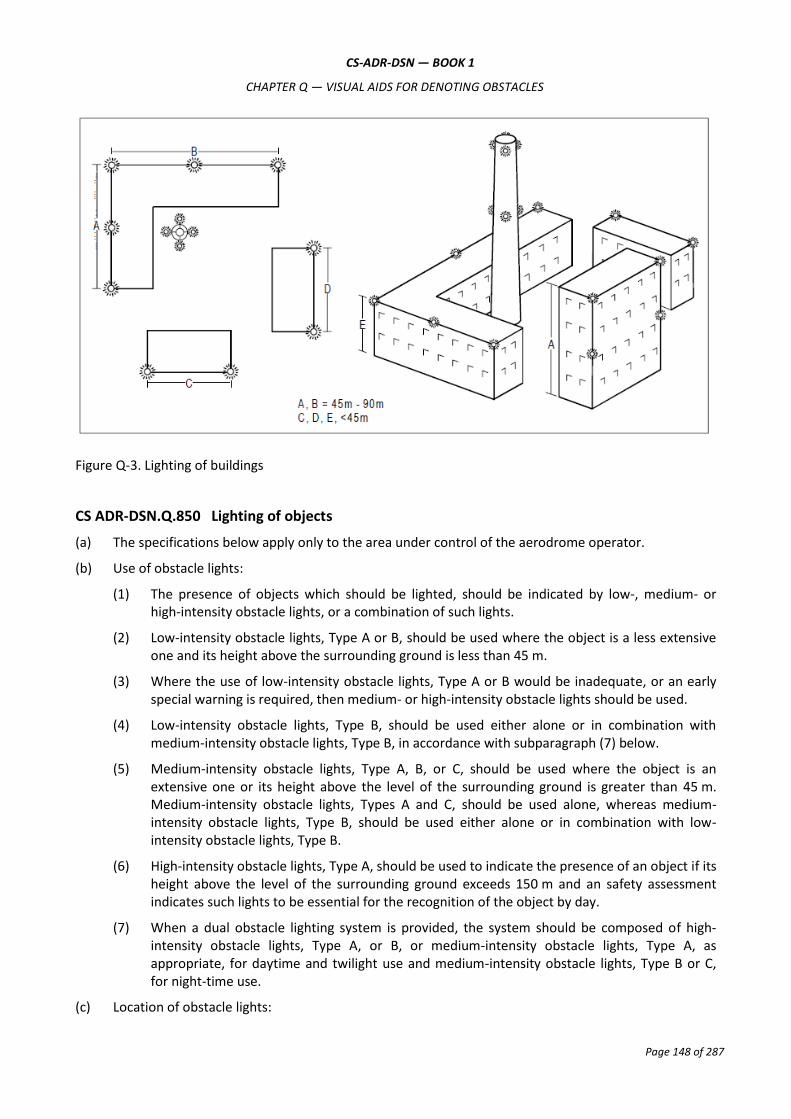
CS-ADR-DSN — BOOK 1
CHAPTER Q — VISUAL AIDS FOR DENOTING OBSTACLES
Page 148 of 287
Figure Q-3. Lighting of buildings
CS ADR-DSN.Q.850 Lighting of objects
(a) The specifications below apply only to the area under control of the aerodrome operator.
(b) Use of obstacle lights:
(1) The presence of objects which should be lighted, should be indicated by low-, medium- or high-intensity obstacle lights, or a combination of such lights.
(2) Low-intensity obstacle lights, Type A or B, should be used where the object is a less extensive one and its height above the surrounding ground is less than 45 m.
(3) Where the use of low-intensity obstacle lights, Type A or B would be inadequate, or an early special warning is required, then medium- or high-intensity obstacle lights should be used.
(4) Low-intensity obstacle lights, Type B, should be used either alone or in combination with medium-intensity obstacle lights, Type B, in accordance with subparagraph (7) below.
(5) Medium-intensity obstacle lights, Type A, B, or C, should be used where the object is an extensive one or its height above the level of the surrounding ground is greater than 45 m. Medium-intensity obstacle lights, Types A and C, should be used alone, whereas medium-intensity obstacle lights, Type B, should be used either alone or in combination with low-intensity obstacle lights, Type B.
(6) High-intensity obstacle lights, Type A, should be used to indicate the presence of an object if its height above the level of the surrounding ground exceeds 150 m and an safety assessment indicates such lights to be essential for the recognition of the object by day.
(7) When a dual obstacle lighting system is provided, the system should be composed of high-intensity obstacle lights, Type A, or B, or medium-intensity obstacle lights, Type A, as appropriate, for daytime and twilight use and medium-intensity obstacle lights, Type B or C, for night-time use.
(c) Location of obstacle lights:
CS-ADR-DSN — BOOK 1
CHAPTER Q — VISUAL AIDS FOR DENOTING OBSTACLES
Page 149 of 287
(1) One or more low-, medium- or high-intensity obstacle lights should be located as close as practicable to the top of the object. The top lights should be so arranged as to at least indicate the points or edges of the object highest in relation to the obstacle limitation surface.
(2) In the case of chimney or other structure of like function, the top lights should be placed sufficiently below the top so as to minimise contamination by smoke, etc. (see Figures Q-2 and Q-3).
(3) In the case of a tower or antenna structure indicated by high-intensity obstacle lights by day with an appurtenance, such as a rod or an antenna, greater than 12 m where it is not practicable to locate a high-intensity obstacle light on the top of the appurtenance, such a light should be located at the highest practicable point, and if practicable, a medium-intensity obstacle light, Type A, mounted on the top.
(4) In the case of an extensive object or of a group of closely spaced objects, top lights should be displayed at least on the points or edges of the objects highest in relation to the obstacle limitation surface so as to indicate the general definition and the extent of the objects. If two or more edges are of the same height, the edge nearest the landing area should be marked. Where low-intensity lights are used, they should be spaced at longitudinal intervals not exceeding 45 m. Where medium-intensity lights are used, they should be spaced at longitudinal intervals not exceeding 900 m.
(5) When the obstacle limitation surface concerned is sloping and the highest point above the obstacle limitation surface is not the highest point of the object, additional obstacle lights should be placed on the highest point of the object.
(6) Where an object is indicated by medium-intensity obstacle lights, Type A, and the top of the object is more than 105 m above the level of the surrounding ground, or the elevation of tops of nearby buildings (when the object to be marked is surrounded by buildings), additional lights should be provided at intermediate levels. These additional intermediate lights should be spaced as equally as practicable, between the top lights and ground level or the level of tops of nearby buildings as appropriate, with the spacing not exceeding 105 m (see subparagraph (b)(5) above).
(7) Where an object is indicated by medium-intensity obstacle lights, Type B, and the top of the object is more than 45 m above the level of the surrounding ground or the elevation of tops of nearby buildings (when the object to be marked is surrounded by buildings), additional lights should be provided at intermediate levels. These additional intermediate lights should be alternately low-intensity obstacle lights, Type B, and medium-intensity obstacle lights, Type B, and should be spaced as equally as practicable, between the top lights and ground level or the level of tops of nearby buildings as appropriate, with the spacing not exceeding 52 m.
(8) Where an object is indicated by medium-intensity obstacle lights, Type C, and the top of the object is more than 45 m above the level of the surrounding ground or the elevation of tops of nearby buildings (when the object to be marked is surrounded by buildings), additional lights should be provided at intermediate levels. These additional intermediate lights should be spaced as equally as practicable, between the top lights and ground level or the level of tops of nearby buildings as appropriate, with the spacing not exceeding 52 m.
(9) Where high-intensity obstacle lights, Type A, are used, they should be spaced at uniform intervals not exceeding 105 m between the ground level and the top light(s) specified in paragraph (c)(1) above, except that where an object to be marked is surrounded by buildings, the elevation of the tops of the buildings may be used as the equivalent of the ground level when determining the number of light levels.
(10) Where high-intensity obstacle lights, Type B, are used, they should be located at three levels:

CS-ADR-DSN — BOOK 1
CHAPTER Q — VISUAL AIDS FOR DENOTING OBSTACLES
Page 150 of 287
(i) at the top of the tower;
(ii) at the lowest level of the catenary of the wires or cables; and
(iii) at approximately midway between these two levels.
(11) The installation setting angles for high-intensity obstacle lights, Types A and B, should be in accordance with Table Q-1.
(12) The number and arrangement of low-, medium- or high-intensity obstacle lights at each level to be marked should be such that the object is indicated from every angle in azimuth. Where a light is shielded in any direction by another part of the object, or by an adjacent object, additional lights should be provided on that object in such a way as to retain the general definition of the object to be lighted. If the shielded light does not contribute to the definition of the object to be lighted, it may be omitted.
(d) Low-intensity obstacle lights — Characteristics:
(1) Low-intensity obstacle lights on fixed objects, Types A and B, should be fixed-red lights.
(2) Low-intensity obstacle lights, Types A and B, should be in accordance with the specifications in Table Q-2.
(3) Low-intensity obstacle lights, Type C, displayed on vehicles associated with emergency or security should be flashing-blue and those displayed on other vehicles should be flashing-yellow.
(4) Low-intensity obstacle lights, Type D, displayed on follow-me vehicles should be flashing-yellow.
(5) Low-intensity obstacle lights, Types C and D, should be in accordance with the specifications in Table Q-2.
(6) Low-intensity obstacle lights on objects with limited mobility such as aerobridges, should be fixed-red. The intensity of the lights should be sufficient to ensure conspicuity considering the intensity of the adjacent lights and the general levels of illumination against which they would normally be viewed.
(7) Low-intensity obstacle lights on objects with limited mobility should as a minimum be in accordance with the specifications for low-intensity obstacle lights, Type A, in Table Q-2.
(e) Medium-intensity obstacle lights — Characteristics:
(1) Medium-intensity obstacle lights, Type A, should be flashing-white lights, Type B should be flashing-red lights, and Type C should be fixed-red lights.
(2) Medium-intensity obstacle lights, Types A, B and C, should be in accordance with the specifications in Table Q-2.
(3) Medium-intensity obstacle lights, Types A and B, located on an object should flash simultaneously.
(f) High-intensity obstacle lights — Characteristics:
(1) High-intensity obstacle lights, Types A and B, should be flashing-white lights.
(2) High-intensity obstacle lights, Types A and B, should be in accordance with the specifications in Table Q-2.
(3) High-intensity obstacle lights, Type A, located on an object should flash simultaneously.

CS-ADR-DSN — BOOK 1
CHAPTER Q — VISUAL AIDS FOR DENOTING OBSTACLES
Page 151 of 287
(4) High-intensity obstacle lights, Type B, indicating the presence of a tower supporting overhead wires, cables, etc., should flash sequentially; first the middle light, second the top light, and last the bottom light. The intervals between flashes of the lights should approximate the following ratios:
Flash interval between Ratio of cycle time
Middle and top light 1:13
Top and bottom light 2:13
Bottom and middle light 10:13
Height of light unit above terrain Angle of the peak of the beam above the horizontal
Greater than 151 m AGL 0°
122 m to 151 m AGL 1°
92 m to 122 m AGL 2°
Less than 92 m AGL 3°
Table Q-1. Installation setting angles for high-intensity obstacle lights

CS-ADR-DSN — BOOK 1
CHAPTER Q — VISUAL AIDS FOR DENOTING OBSTACLES
Page 152 of 287
1 2 3 4 5 6 7 8 9 10 11 12
Light type Colour Signal type/flash rate
Peak intensity (cd) at given background luminance Vertical
beam spread
a
Intensity (cd) at given elevation angles when the light unit is levelled
d
Above 500 cd/m
2
50-500 cd/m2
Below 50 cd/m
2 -10°
e -1°
f ±0°
f +6° +10°
Low-intensity Type A (fixed obstacle)
Red Fixed N/A 10 mnm 10 mnm 10° ― ― ― 10 mnm g 10 mnm
g
Low-intensity Type B (fixed obstacle)
Red Fixed N/A 32 mnm 32 mnm 10° ― ― ― 32 mnm g 32 mnm
g
Low-intensity Type C (mobile obstacle)
Yellow/blue a
Flashing (60-90 fpm) N/A 40 mnm
b
400 max 40 mnm
b
400 max 12°
h ― ― ― ― ―
Low-intensity Type D (follow-me vehicle)
Yellow Flashing (60-90 fpm) N/A 200 mnm
b
400 max
200 mnm b
400 max 12°
i ― ― ― ― ―
Medium-intensity Type A White Flashing (20-60 fpm) 20 000
b
±25 % 20 000
b
±25 % 2 000
b
±25 % 3° mnm 3°% max
50 % mnm
75 % max
100 % mnm
― ―
Medium-intensity Type B Red Flashing (20-60 fpm) N/A N/A 2 000
b
±25% 3° mnm ― 50 % mnm
100 % mnm
― ―
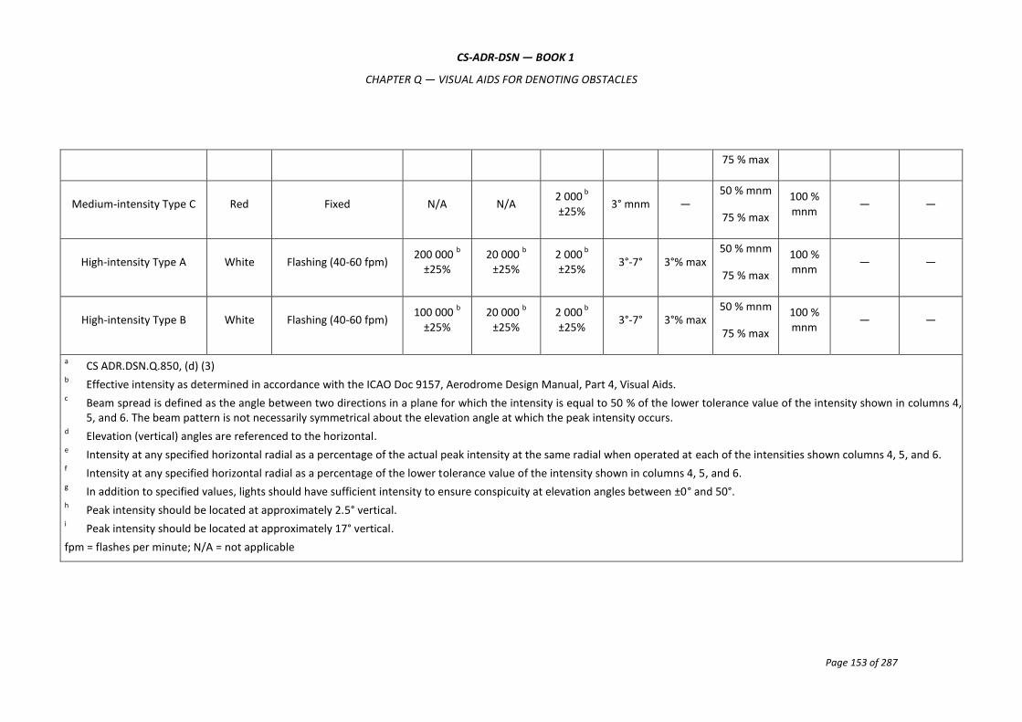
CS-ADR-DSN — BOOK 1
CHAPTER Q — VISUAL AIDS FOR DENOTING OBSTACLES
Page 153 of 287
75 % max
Medium-intensity Type C Red Fixed N/A N/A 2 000
b
±25% 3° mnm ―
50 % mnm
75 % max
100 % mnm
― ―
High-intensity Type A White Flashing (40-60 fpm) 200 000
b
±25% 20 000
b
±25% 2 000
b
±25% 3°-7° 3°% max
50 % mnm
75 % max
100 % mnm
― ―
High-intensity Type B White Flashing (40-60 fpm) 100 000
b
±25% 20 000
b
±25% 2 000
b
±25% 3°-7° 3°% max
50 % mnm
75 % max
100 % mnm
― ―
a CS ADR.DSN.Q.850, (d) (3)
b Effective intensity as determined in accordance with the ICAO Doc 9157, Aerodrome Design Manual, Part 4, Visual Aids.
c Beam spread is defined as the angle between two directions in a plane for which the intensity is equal to 50 % of the lower tolerance value of the intensity shown in columns 4,
5, and 6. The beam pattern is not necessarily symmetrical about the elevation angle at which the peak intensity occurs. d Elevation (vertical) angles are referenced to the horizontal.
e Intensity at any specified horizontal radial as a percentage of the actual peak intensity at the same radial when operated at each of the intensities shown columns 4, 5, and 6.
f Intensity at any specified horizontal radial as a percentage of the lower tolerance value of the intensity shown in columns 4, 5, and 6.
g In addition to specified values, lights should have sufficient intensity to ensure conspicuity at elevation angles between ±0° and 50°.
h Peak intensity should be located at approximately 2.5° vertical.
i Peak intensity should be located at approximately 17° vertical.
fpm = flashes per minute; N/A = not applicable

CS-ADR-DSN — BOOK 1
CHAPTER Q — VISUAL AIDS FOR DENOTING OBSTACLES
Page 154 of 287
Table Q-2. Characteristics of obstacle lights
Table Q-3. Obstacle marking band widths
CS-ADR-DSN — BOOK 1
CHAPTER R — VISUAL AIDS FOR DENOTING RESTRICTED USE AREAS
Page 155 of 287
CHAPTER R — VISUAL AIDS FOR DENOTING RESTRICTED USE AREAS
CS ADR-DSN.R.855 Closed runways and taxiways, or parts thereof
(a) Applicability of closed marking:
(1) A closed marking should be displayed on a runway, or taxiway, or portion thereof which is permanently closed to the use of all aircraft.
(2) A closed marking should be displayed on a temporarily closed runway, or taxiway, or portion thereof, except that such marking may be omitted when the closing is of short duration, and adequate warning by air traffic services is provided.
(b) Location of closed markings: On a runway, a closed marking should be placed at each end of the runway, or portion thereof, declared closed, and additional markings should be so placed that the maximum interval between markings does not exceed 300 m. On a taxiway a closed marking should be placed at least at each end of the taxiway or portion thereof closed.
(c) Characteristics of closed markings:
(1) The closed marking should be of the form and proportions as detailed in Figure R-1, Illustration (a), when displayed on a runway, and should be of the form and proportions as detailed in Figure R-1, Illustration (b), when displayed on a taxiway. The marking should be white when displayed on a runway and should be yellow when displayed on a taxiway.
(2) When a runway, or taxiway, or portion thereof is permanently closed, all normal runway and taxiway markings should be obliterated.
(d) Lighting on a closed runway, or taxiway, or portion thereof should not be operated, except as required for maintenance purposes.
(e) In addition to closed markings, when the runway, or taxiway, or portion thereof closed is intercepted by a usable runway or taxiway which is used at night, unserviceability lights should be placed across the entrance to the closed area at intervals not exceeding 3 m (see CS ADR-DSN.R.870 (c) (2)).

CS-ADR-DSN — BOOK 1
CHAPTER R — VISUAL AIDS FOR DENOTING RESTRICTED USE AREAS
Page 156 of 287
Figure R-1. Runway and taxiway closed markings
CS ADR-DSN.R.860 Non-load-bearing surfaces
(a) Shoulders for taxiways, runway turn pads, holding bays and aprons, and other non-load-bearing surfaces which cannot readily be distinguished from load-bearing surfaces and which, if used by aircraft, might result in damage to the aircraft, should have the boundary between such areas and the load-bearing surface marked by a taxi side stripe marking (specifications for markings are in CS ADR-DSN.L.550).
(b) A taxi side stripe marking should consist of a pair of solid lines, each 15 cm wide and spaced 15 cm apart, and the same colour as the taxiway centre line marking.
CS ADR-DSN.R.865 Pre-threshold area
(a) Applicability of Pre-threshold area: When the surface before a threshold is paved and exceeds 60 m in length, and is not suitable for normal use by aircraft, the entire length before the threshold should be marked with a chevron marking.
(b) Location: A chevron marking should point in the direction of the runway and be placed as shown in Figure R-2.
(c) Characteristics: A chevron marking should be of conspicuous colour and contrast with the colour used for the runway markings; it should preferably be yellow and should have an overall width of at least 0.9 m.
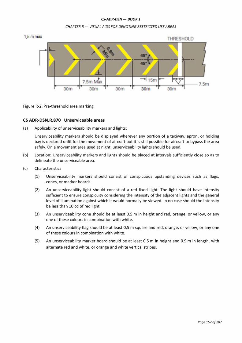
CS-ADR-DSN — BOOK 1
CHAPTER R — VISUAL AIDS FOR DENOTING RESTRICTED USE AREAS
Page 157 of 287
Figure R-2. Pre-threshold area marking
CS ADR-DSN.R.870 Unserviceable areas
(a) Applicability of unserviceability markers and lights:
Unserviceability markers should be displayed wherever any portion of a taxiway, apron, or holding bay is declared unfit for the movement of aircraft but it is still possible for aircraft to bypass the area safely. On a movement area used at night, unserviceability lights should be used.
(b) Location: Unserviceability markers and lights should be placed at intervals sufficiently close so as to delineate the unserviceable area.
(c) Characteristics
(1) Unserviceability markers should consist of conspicuous upstanding devices such as flags, cones, or marker boards.
(2) An unserviceability light should consist of a red fixed light. The light should have intensity sufficient to ensure conspicuity considering the intensity of the adjacent lights and the general level of illumination against which it would normally be viewed. In no case should the intensity be less than 10 cd of red light.
(3) An unserviceability cone should be at least 0.5 m in height and red, orange, or yellow, or any one of these colours in combination with white.
(4) An unserviceability flag should be at least 0.5 m square and red, orange, or yellow, or any one of these colours in combination with white.
(5) An unserviceability marker board should be at least 0.5 m in height and 0.9 m in length, with
alternate red and white, or orange and white vertical stripes.

CS-ADR-DSN — BOOK 1
CHAPTER S — ELECTRICAL SYSTEMS
Page 158 of 287
CHAPTER S — ELECTRICAL SYSTEMS
CS ADR-DSN.S.875 Electrical power supply systems for air navigation facilities
(a) Adequate primary power supply should be available at aerodromes for the safe functioning of air navigation facilities.
(b) The design and provision of electrical power systems for aerodrome visual and radio navigation aids should be such that an equipment failure should not leave the pilot with inadequate visual and non-visual guidance, or misleading information.
(c) Electric power supply connections to those facilities for which secondary power is required should be so arranged that the facilities are automatically connected to the secondary power supply on failure of the primary source of power.
(d) The time interval between failure of the primary source of power and the complete restoration of the services required by CS ADR-DSN.S.880(d) should be as short as practicable, except that for visual aids associated with non-precision, precision approach, or take-off runways the requirements of Table S-1 for maximum switch-over times should apply.
CS ADR-DSN.S.880 Electrical power supply systems for visual aids
(a) For a precision approach runway, a secondary power supply capable of meeting the requirements of Table S-1 for the appropriate category of precision approach runway should be provided. Electric power supply connections to those facilities for which secondary power is required should be so arranged that the facilities are automatically connected to the secondary power supply on failure of the primary source of power.
(b) For a runway meant for take-off in runway visual range conditions less than a value of 800 m, a secondary power supply capable of meeting the relevant requirements of Table S-1 should be provided.
(c) At an aerodrome where the primary runway is a non-precision approach runway, a secondary power supply capable of meeting the requirements of Table 1 should be provided except that a secondary power supply for visual aids need not be provided for more than one non-precision approach runway.
(d) The following aerodrome facilities should be provided with a secondary power supply capable of supplying power when there is a failure of the primary power supply:
(1) the signalling lamp and the minimum lighting necessary to enable air traffic services personnel to carry out their duties;
(2) obstacle lights which are essential to ensure the safe operation of aircraft;
(3) approach, runway and taxiway lighting as specified in CS ADR-DSN.M.625 to CS ADR-DSN.M.745;
(4) meteorological equipment;
(5) essential equipment and facilities for the parking position if provided, in accordance with CS ADR-DSN.M.750(a) and CS ADR-DSN.M.755(a); and
(6) illumination of apron areas over which passengers may walk.

CS-ADR-DSN — BOOK 1
CHAPTER S — ELECTRICAL SYSTEMS
Page 159 of 287
CS ADR-DSN.S.885 System design
(a) For a runway meant for use in runway visual range conditions less than a value of 550 m, the electrical systems for the power supply, lighting, and control of the lighting systems included in Table S-1 should be so designed that an equipment failure should not leave the pilot with inadequate visual guidance or misleading information.
(b) Where the secondary power supply of an aerodrome is provided by the use of duplicate feeders, such supplies should be physically and electrically separate so as to ensure the required level of availability and independence.
(c) Where a runway forming part of a standard taxi-route is provided with runway lighting and taxiway lighting, the lighting systems should be interlocked to preclude the possibility of simultaneous operation of both forms of lighting.
CS ADR-DSN.S.890 Monitoring
(a) A system of monitoring should be employed to indicate the operational status of the lighting systems.
(b) Where lighting systems are used for aircraft control purposes, such systems should be monitored automatically so as to provide an indication of any fault which may affect the control functions. This information should be automatically relayed to the air traffic service unit.
(c) Where a change in the operational status of lights has occurred, an indication should be provided within two seconds for a stop bar at a runway-holding position and within five seconds for all other types of visual aids.
(d) For a runway meant for use in runway visual range conditions less than a value of 550 m, the lighting systems detailed in Table S-1 should be monitored automatically so as to provide an indication when the serviceability level of any element falls below a minimum serviceability level specified in CS ADR-DSN.S.895. This information should be automatically relayed to the maintenance crew.
(e) For a runway meant for use in runway visual range conditions less than a value of 550 m, the lighting systems detailed in Table S-1 should be monitored automatically to provide an indication when the serviceability level of any element falls below a minimum level specified in CS ADR-DSN.S.895, below which operations should not continue. This information should be automatically relayed to the air traffic services unit and displayed in a prominent position.
CS ADR-DSN.S.895 Serviceability levels
(a) A light should be deemed to be unserviceable when the main beam average intensity is less than 50 % of the value specified in the appropriate Figure in CS ADR-DSN.U.940. For light units where the designed main beam average intensity is above the value shown in CS ADR-DSN.U.940, the 50 % value should be related to that design value.
(b) A system of preventive maintenance of visual aids should be employed to ensure lighting and marking system reliability.
(c) The system of preventive maintenance employed for a precision approach runway category II or III should have as its objective that, during any period of category II or III operations, all approach and runway lights are serviceable and that, in any event, at least:
(1) 95 % of the lights are serviceable in each of the following particular significant elements:
(i) precision approach category II and III lighting system, the inner 450 m;

CS-ADR-DSN — BOOK 1
CHAPTER S — ELECTRICAL SYSTEMS
Page 160 of 287
(ii) runway centre line lights;
(iii) runway threshold lights; and
(iv) runway edge lights.
(2) 90 % of the lights are serviceable in the touchdown zone lights;
(3) 85 % of the lights are serviceable in the approach lighting system beyond 450 m; and
(4) 75 % of the lights are serviceable in the runway end lights.
(5) In order to provide continuity of guidance, the allowable percentage of unserviceable lights
should not be permitted in such a way as to alter the basic pattern of the lighting system.
(6) Additionally, an unserviceable light should not be permitted adjacent to another unserviceable light, except in a barrette or a crossbar where two adjacent unserviceable lights may be permitted.
(d) The system of preventive maintenance employed for a stop bar provided at a runway-holding position used in conjunction with a runway intended for operations in runway visual range conditions less than a value of 550 m should have the following objectives:
(1) no more than two lights should remain unserviceable; and
(2) two adjacent lights should not remain unserviceable unless the light spacing is significantly less than that specified.
(e) The system of preventive maintenance employed for a taxiway intended for use in runway visual range conditions less than a value of 550 m should have as its objective that no two adjacent taxiway centre line lights be unserviceable.
(f) The system of preventive maintenance employed for a precision approach runway category I should have as its objective that, during any period of category I operations, all approach and runway lights are serviceable and that, in any event, at least 85 % of the lights are serviceable in each of the following:
(1) precision approach category I lighting system;
(2) runway threshold lights;
(3) runway edge lights; and
(4) runway end lights.
In order to provide continuity of guidance an unserviceable light should not be permitted adjacent to another unserviceable light unless the light spacing is significantly less than that specified.
(g) The system of preventive maintenance employed for a runway meant for take-off in runway visual range conditions less than a value of 550 m should have as its objective that, during any period of operations, all runway lights are serviceable, and that in any event:
(1) at least 95 % of the lights are serviceable in the runway centre line lights (where provided) and in the runway edge lights; and;
(2) at least 75 % of the lights are serviceable in the runway end lights.
In order to provide continuity of guidance, an unserviceable light should not be permitted adjacent to another unserviceable light.
(h) The system of preventive maintenance employed for a runway meant for take-off in runway visual range conditions of a value of 550 m or greater should have as its objective that, during any period of

CS-ADR-DSN — BOOK 1
CHAPTER S — ELECTRICAL SYSTEMS
Page 161 of 287
operations, all runway lights are serviceable, and that, in any event, at least 85 % of the lights are serviceable in the runway edge lights and runway end lights. In order to provide continuity of guidance, an unserviceable light should not be permitted adjacent to another unserviceable light.

CS-ADR-DSN — BOOK 1
CHAPTER S — ELECTRICAL SYSTEMS
Page 162 of 287
Runway Lighting aids requiring power Maximum switch-over
time
Non-instrument
Visual approach slope indicatorsa
Runway edgeb
Runway thresholdb
Runway endb
Obstaclea
See CS ADR-DSN.M.875(d) and CS ADR-DSN.M.880(d)
Non-precision approach
Approach lighting system
Visual approach slope indicatorsa, d
Runway edged
Runway thresholdd
Runway endd
Obstaclea
15 seconds
15 seconds
15 seconds
15 seconds
15 seconds
15 seconds
Precision approach category I
Approach lighting system
Runway edged
Visual approach slope indicatorsa, d
Runway thresholdd
Runway end
Essential taxiwaya
Obstaclea
15 seconds
15 seconds
15 seconds
15 seconds
15 seconds
15 seconds
15 seconds
Precision approach category II/III
Inner 300 m of the approach lighting system
Other parts of the approach lighting system
Obstaclea
Runway edge
Runway threshold
Runway end
Runway centre line
Runway touchdown zone
All stop bars
Essential taxiway
1 second
15 seconds
15 seconds
15 seconds
1 second
1 second
1 second
1 second
1 second
15 seconds
Runway meant for take-off in runway visual range conditions less than a value of 800 m
Runway edge
Runway end
Runway centre line
All stop bars
Essential taxiwaya
Obstaclea
15 seconds
1 second
1 second
1 second
15 seconds
15 seconds

CS-ADR-DSN — BOOK 1
CHAPTER S — ELECTRICAL SYSTEMS
Page 163 of 287
Table S-1. Secondary power supply requirements
a. Supplied with secondary power when their operation is essential to the safety of flight operation.
b. The use of emergency lighting should be in accordance with any procedures established.
c. One second where no runway centre line lights are provided.
d. One second where approaches are over hazardous or precipitous terrain.

CS-ADR-DSN — BOOK 1
CHAPTER S — ELECTRICAL SYSTEMS
Page 164 of 287
Light type CAT II/III Approach CAT I Approach RVR<550m take-off RVR>550m take-off
Approach inner 450 m
95 % 85 % - -
Approach outer 450 m
85 % 85 % - -
Runway threshold
95 % 85 % - -
Runway centre line
95 % 85 % 95 % 85 %
Runway edge
95 % 85 % 95 % 85 %
Runway end
75 % 85 % 75 % 85 %
Touchdown zone
90 % (85 %)a - -
Note (a): If touchdown zone lights are available.
Table S-2. Allowable percentages of serviceable lights

CS-ADR-DSN — BOOK 1
CHAPTER T — AERODROME OPERTIONAL SERVICES, EQUIPMENT AND INSTALLATION
Page 165 of 287
CHAPTER T — AERODROME OPERATIONAL SERVICES, EQUIPMENT AND INSTALLATION
CS ADR-DSN.T.900 Emergency access and service roads
Emergency access roads should be equipped with a road-holding position at all intersections with runway and taxiways.
CS ADR-DSN.T.905 Fire stations
(a) All rescue and firefighting vehicles should normally be housed in a fire station. Satellite fire stations should be provided whenever the response time cannot be achieved from a single fire station.
(b) The fire station should be located so that the access for rescue and firefighting vehicles into the runway area is direct and clear, requiring a minimum number of turns.
(c) The fire station, and any satellite fire stations, should be located outside taxiway and runway strips, and not infringe obstacle limitation surfaces.
CS ADR-DSN.T.910 Equipment frangibility requirements
Equipment and structures should be so designed to meet the appropriate frangibility characteristics, when required.
CS ADR-DSN.T.915 Siting of equipment and installations on operational areas
(a) Equipment and installations should be sited as far away from the runway and taxiway centre lines as practicable.
(b) Unless its function requires it to be there for air navigation or for aircraft safety purposes, no equipment or installation endangering an aircraft should be located:
(1) on a runway strip, a runway end safety area, a taxiway strip, or within the following distances:
Code Letter
Distance between taxiway, other than aircraft stand taxilane, centre line to object (metres)
A 15.5
B 20
C 26
D 37
E 43.5
F 51
if it would endanger an aircraft, or
(2) on a clearway if it would endanger an aircraft in the air.
(c) Any equipment or installation required for air navigation or for aircraft safety purposes which should be located:
(1) on that portion of a runway strip within:

CS-ADR-DSN — BOOK 1
CHAPTER T — AERODROME OPERTIONAL SERVICES, EQUIPMENT AND INSTALLATION
Page 166 of 287
(i) 75 m of the runway centre line where the code number is 3 or 4; or
(ii) 45 m of the runway centre line where the code number is 1 or 2; or
(2) on a runway end safety area, a taxiway strip, or within the distances specified in Table D-1; or
(3) on a clearway and which would endanger an aircraft in the air;
should be frangible and mounted as low as possible.
(d) Unless its function requires it to be there for air navigation or for aircraft safety purposes or after safety assessment it is determined that it would not adversely affect the safety or significantly affect the regularity of operations of aeroplanes, no equipment or installation should be located within 240 m from the end of the strip and within:
(1) 60 m of the extended centre line where the code number is 3 or 4; or
(2) 45 m of the extended centre line where the code number is 1 or 2;
of a precision approach runway category I, II or III.
(e) Any equipment or installation required for air navigation or for aircraft safety purposes which should be located on or near a strip of a precision approach runway category I, II, or III and which:
(1) is situated on that portion of the strip within 77.5 m of the runway centre line where the code number is 4 and the code letter is F; or
(2) is situated within 240 m from the end of the strip and within:
(i) 60 m of the extended runway centre line where the code number is 3 or 4; or
(ii) 45 m of the extended runway centre line where the code number is 1 or 2; or
(3) penetrates the inner approach surface, the inner transitional surface, or the balked landing surface;
should be frangible and mounted as low as possible.
(f) Any equipment or installation required for air navigation or for aircraft safety purposes that is an obstacle of operational significance in accordance with CS ADR-DSN.J.470 (d), CS ADR-DSN.J.475 (e), CS ADR-DSN.J.480 (g), or CS ADR-DSN.J.485 (e) should be frangible and mounted as low as possible.
(g) Any equipment or installation required for air navigation or for aircraft safety purposes which should be located on the non-graded portion of a runway strip should be regarded as an obstacle and should be frangible and mounted as low as possible.
CS ADR-DSN.T.920 Fencing
(a) The safety objective of fencing is to prevent animals or unauthorised persons that could be a safety risk to aircraft operations, to enter the aerodrome.
(b) Fencing should be sited as far away from the runway and taxiway centre lines as practicable.
(c) Suitable means of protection such as fence or other suitable barrier should be provided on an aerodrome to prevent the entrance to the aerodrome:
(1) by non-flying animals large enough to be a hazard to aircraft; and/or
(2) by an unauthorised person.
This includes the barring of sewers, ducts, tunnels, etc. where necessary to prevent access.

CS-ADR-DSN — BOOK 1
CHAPTER T — AERODROME OPERTIONAL SERVICES, EQUIPMENT AND INSTALLATION
Page 167 of 287
(d) Suitable means of protection should be provided to deter the inadvertent or premeditated access of
unauthorised persons into ground installations and facilities essential for the safety of civil aviation
located off the aerodrome.

CS-ADR-DSN — BOOK 1
CHAPTER U — COLOURS FOR AERONAUTICAL GROUND LIGHTS, MARKINGS, SIGNS AND PANELS
Page 168 of 287
CHAPTER U — COLOURS FOR AERONAUTICAL GROUND LIGHTS, MARKINGS, SIGNS AND PANELS
CS ADR-DSN.U.925 General
(a) The specifications in this Chapter define the chromaticity limits of colours to be used for aeronautical ground lights, markings, signs, and panels. The specifications are in accord with the specifications of the International Commission on Illumination (CIE).
(b) The chromaticities are expressed in terms of the standard observer and coordinate system adopted by the International Commission on Illumination (CIE).
CS ADR-DSN.U.930 Colours for aeronautical ground lights
(a) The chromaticities of aeronautical ground lights should be within the following boundaries:
CIE Equations (see Figure U-1):
(1) Red
Purple boundary y = 0.980 – x
Yellow boundary y = 0.335
(2) Yellow
Red boundary y = 0.382
White boundary y = 0.790 – 0.667x
Green boundary y = x – 0.120
(3) Green
Yellow boundary x = 0.360 – 0.080y
White boundary x = 0.650y
Blue boundary y = 0.390 – 0.171x
(4) Blue
Green boundary y = 0.805x + 0.065
White boundary y = 0.400 – x
Purple boundary x = 0.600y + 0.133
(5) White
Yellow boundary x = 0.500
Blue boundary x = 0.285
Green boundary y = 0.440
and y = 0.150 + 0.640x
Purple boundary y = 0.050 + 0.750x
and y = 0.382
(6) Variable white

CS-ADR-DSN — BOOK 1
CHAPTER U — COLOURS FOR AERONAUTICAL GROUND LIGHTS, MARKINGS, SIGNS AND PANELS
Page 169 of 287
Yellow boundary x = 0.255 + 0.750y
and x = 1.185 – 1.500y
Blue boundary x = 0.285
Green boundary y = 0.440
and y = 0.150 + 0.640x
Purple boundary y = 0.050 + 0.750x
and y = 0.382
(b) Where increased certainty of recognition is more important than maximum visual range, green signals should be within the following boundaries:
(1) Yellow boundary y = 0.726 – 0.726x
(2) White boundary x = 0.625y – 0.041
(3) Blue boundary y = 0.390 – 0.171x
(c) Discrimination between lights
(1) If there is a requirement to discriminate yellow and white from each other, they should be displayed in close proximity of time or space as, for example, by being flashed successively from the same beacon.
(2) If there is a requirement to discriminate yellow from green and/or white, as for example on exit taxiway centre line lights, the y coordinates of the yellow light should not exceed a value of 0.40. The limits of white have been based on the assumption that they should be used in situations in which the characteristics (colour temperature) of the light source should be substantially constant.
(3) The colour variable white is intended to be used only for lights that are to be varied in intensity, e.g. to avoid dazzling. If this colour is to be discriminated from yellow, the lights should be so designed and operated that:
(i) the x coordinate of the yellow is at least 0.050 greater than the x coordinate of the white; and
(ii) the disposition of the lights should be such that the yellow lights are displayed simultaneously and in close proximity to the white lights.
(4) The colour of aeronautical ground lights should be verified as being within the boundaries specified in Figure U-1 by measurement at five points within the area limited by the innermost isocandela curve in the isocandela diagrams in CS ADR-DSN.U.940, with operation at rated current or voltage. In the case of elliptical or circular isocandela curves, the colour measurements should be taken at the centre and at the horizontal and vertical limits. In the case of rectangular isocandela curves, the colour measurements should be taken at the centre and the limits of the diagonals (corners). In addition, the colour of the light should be checked at the outermost isocandela curve to ensure that there is no colour shift that might cause signal confusion to the pilot.
(5) For the outermost isocandela curve, a measurement of colour coordinates should be made and recorded for review and judgement of acceptability.
(6) If certain light units have application so that they may be viewed and used by pilots from directions beyond that of the outermost isocandela curve (e.g. stop bar lights at significantly wide runway-holding positions), then an assessment of the actual application should be
CS-ADR-DSN — BOOK 1
CHAPTER U — COLOURS FOR AERONAUTICAL GROUND LIGHTS, MARKINGS, SIGNS AND PANELS
Page 170 of 287
conducted, and if necessary, a check of colour shift at angular ranges beyond the outermost curve carried out.
(7) In the case of visual approach slope indicators and other light units having a colour transition sector, the colour should be measured at points in accordance with paragraph (4) above, except that the colour areas should be treated separately and no point should be within 0.5 degrees of the transition sector.
CS ADR-DSN.U.935 Colours for markings, signs and panels
(a) The specifications of surface colours given below apply only to freshly coloured surfaces. Colours used for markings, signs, and panels usually change with time and, therefore, require renewal.
(b) The specifications in paragraph (f) below for internally illuminated panels are interim in nature and are based on the CIE specifications for internally illuminated signs. It is intended that these specifications should be reviewed and updated as and when CIE develops specifications for internally illuminated panels.
(c) The chromaticities and luminance factors of ordinary colours, colours of retroreflective materials, and colours of internally illuminated (internally illuminated) signs and panels should be determined under the following standard conditions:
(1) angle of illumination: 45°;
(2) direction of view: perpendicular to surface; and
(3) illuminant: CIE standard illuminant D65.
(d) The chromaticity and luminance factors of ordinary colours for markings and externally illuminated signs and panels should be within the following boundaries when determined under standard conditions.
CIE Equations (see Figure U-2):
(1) Red
Purple boundary y = 0.345 – 0.051x
White boundary y = 0.910 – x
Orange boundary y = 0.314 + 0.047x
Luminance factor ß = 0.07 (minimum)
(2) Orange
Red boundary y = 0.285 + 0.100x
White boundary y = 0.940 – x
Yellow boundary y = 0.250 + 0.220x
Luminance factor ß = 0.20 (minimum)
(3) Yellow
Orange boundary y = 0.108 + 0.707x
White boundary y = 0.910 – x
Green boundary y = 1.35x – 0.093

CS-ADR-DSN — BOOK 1
CHAPTER U — COLOURS FOR AERONAUTICAL GROUND LIGHTS, MARKINGS, SIGNS AND PANELS
Page 171 of 287
Luminance factor ß = 0.45 (minimum)
(4) White
Purple boundary y = 0.010 + x
Blue boundary y = 0.610 – x
Green boundary y = 0.030 + x
Yellow boundary y = 0.710 – x
Luminance factor ß = 0.75 (minimum)
(5) Black
Purple boundary y = x – 0.030
Blue boundary y = 0.570 – x
Green boundary y = 0.050 + x
Yellow boundary y = 0.740 – x
Luminance factor ß = 0.03 (maximum)
(6) Yellowish green
Green boundary y = 1.317x + 0.4
White boundary y = 0.910 – x
Yellow boundary y = 0.867x + 0.4
(7) Green
Yellow boundary x = 0.313
White boundary y = 0.243 + 0.670x
Blue boundary y = 0.493 – 0.524x
Luminance factor β = 0.10 (minimum)
The small separation between surface red and surface orange is not sufficient to ensure the
distinction of these colours when seen separately.
(e) The chromaticity and luminance factors of colours of retroreflective materials for markings, signs, and panels should be within the following boundaries when determined under standard conditions.
CIE Equations (see Figure U-3):
(1) Red
Purple boundary y = 0.345 – 0.051x
White boundary y = 0.910 – x
Orange boundary y = 0.314 + 0.047x
Luminance factor ß = 0.03 (minimum)
(2) Orange
CS-ADR-DSN — BOOK 1
CHAPTER U — COLOURS FOR AERONAUTICAL GROUND LIGHTS, MARKINGS, SIGNS AND PANELS
Page 172 of 287
Red boundary y = 0.265 + 0.205x
White boundary y = 0.910 – x
Yellow boundary y = 0.207 + 0.390x
Luminance factor ß = 0.14 (minimum)
(3) Yellow
Orange boundary y = 0.160 + 0.540x
White boundary y = 0.910 – x
Green boundary y = 1.35x – 0.093
Luminance factor ß = 0.16 (minimum)
(4) White
Purple boundary y = x
Blue boundary y = 0.610 – x
Green boundary y = 0.040 + x
Yellow boundary y = 0.710 – x
Luminance factor ß = 0.27 (minimum)
(5) Blue
Green boundary y = 0.118 + 0.675x
White boundary y = 0.370 – x
Purple boundary y = 1.65x – 0.187
Luminance factor ß = 0.01 (minimum)
(6) Green
Yellow boundary y = 0.711 – 1.22x
White boundary y = 0.243 + 0.670x
Blue boundary y = 0.405 – 0.243x
Luminance factor ß = 0.03 (minimum)
(f) The chromaticity and luminance factors of colours for luminescent or internally illuminated signs and panels should be within the following boundaries when determined under standard conditions.
CIE Equations (see Figure U-4):
(1) Red
Purple boundary y = 0.345 – 0.051x
White boundary y = 0.910 – x
Orange boundary y = 0.314 + 0.047x
Luminance factor

CS-ADR-DSN — BOOK 1
CHAPTER U — COLOURS FOR AERONAUTICAL GROUND LIGHTS, MARKINGS, SIGNS AND PANELS
Page 173 of 287
(day condition) ß = 0.07 (minimum)
Relative luminance 5 % (minimum)
to white (night
condition) 20 % (max)
(2) Yellow
Orange boundary y = 0.108 + 0.707x
White boundary y = 0.910 – x
Green boundary y = 1.35x – 0.093
Luminance factor
(day condition) ß = 0.45 (minimum)
Relative luminance 30 % (minimum)
to white (night
condition) 80 % (max)
(3) White
Purple boundary y = 0.010 + x
Blue boundary y = 0.610 – x
Green boundary y = 0.030 + x
Yellow boundary y = 0.710 – x
Luminance factor
(day condition) ß = 0.75 (minimum)
Relative luminance
to white (night
conditions) 100 %
(4) Black
Purple boundary y = x – 0.030
Blue boundary y = 0.570 – x
Green boundary y = 0.050 + x
Yellow boundary y = 0.740 – x
Luminance factor
(day condition) ß = 0.03 (max)
Relative luminance
to white (night 0 % (minimum)

CS-ADR-DSN — BOOK 1
CHAPTER U — COLOURS FOR AERONAUTICAL GROUND LIGHTS, MARKINGS, SIGNS AND PANELS
Page 174 of 287
condition) 2 % (maximum)
(5) Green
Yellow boundary x = 0.313
White boundary y = 0.243 + 0.670x
Blue boundary y = 0.493 – 0.524x
Luminance factor
(day conditions) β = 0.10 minimum
Relative luminance 5 % (minimum)
to white (night
conditions) 30 % (maximum)

CS-ADR-DSN — BOOK 1
CHAPTER U — COLOURS FOR AERONAUTICAL GROUND LIGHTS, MARKINGS, SIGNS AND PANELS
Page 175 of 287
Figure U-1. Colours for aeronautical ground lights

CS-ADR-DSN — BOOK 1
CHAPTER U — COLOURS FOR AERONAUTICAL GROUND LIGHTS, MARKINGS, SIGNS AND PANELS
Page 176 of 287
Figure U-2. Ordinary colours for markings and externally illuminated signs and panels

CS-ADR-DSN — BOOK 1
CHAPTER U — COLOURS FOR AERONAUTICAL GROUND LIGHTS, MARKINGS, SIGNS AND PANELS
Page 177 of 287
Figure U-3. Colours of retroreflective materials for markings, signs and panels

CS-ADR-DSN — BOOK 1
CHAPTER U — COLOURS FOR AERONAUTICAL GROUND LIGHTS, MARKINGS, SIGNS AND PANELS
Page 178 of 287
Figure U-4. Colours of luminescent or internally illuminated signs and panels
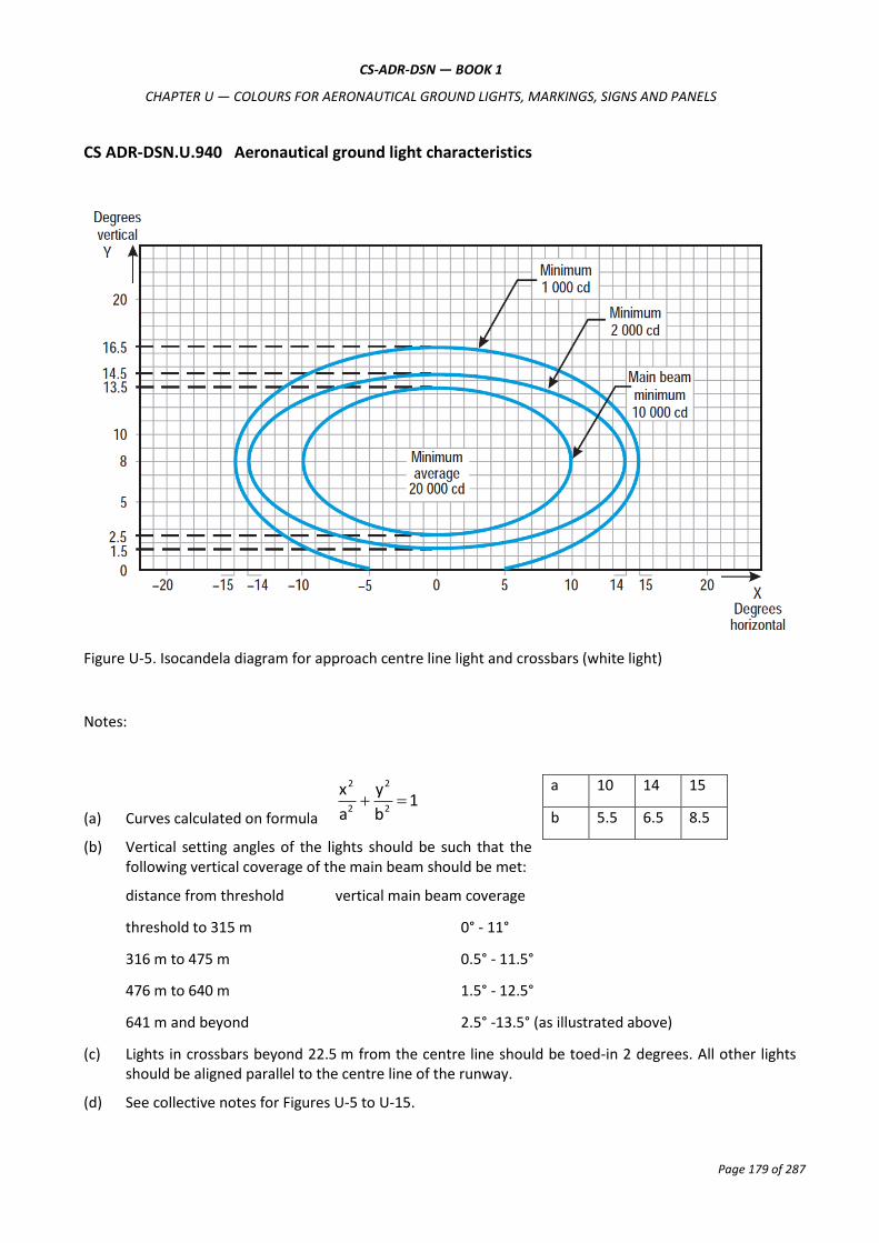
CS-ADR-DSN — BOOK 1
CHAPTER U — COLOURS FOR AERONAUTICAL GROUND LIGHTS, MARKINGS, SIGNS AND PANELS
Page 179 of 287
CS ADR-DSN.U.940 Aeronautical ground light characteristics
Figure U-5. Isocandela diagram for approach centre line light and crossbars (white light)
Notes:
(a) Curves calculated on formula 1
b
y
a
x2
2
2
2
(b) Vertical setting angles of the lights should be such that the following vertical coverage of the main beam should be met:
distance from threshold vertical main beam coverage
threshold to 315 m 0° - 11°
316 m to 475 m 0.5° - 11.5°
476 m to 640 m 1.5° - 12.5°
641 m and beyond 2.5° -13.5° (as illustrated above)
(c) Lights in crossbars beyond 22.5 m from the centre line should be toed-in 2 degrees. All other lights should be aligned parallel to the centre line of the runway.
(d) See collective notes for Figures U-5 to U-15.
a 10 14 15
b 5.5 6.5 8.5

CS-ADR-DSN — BOOK 1
CHAPTER U — COLOURS FOR AERONAUTICAL GROUND LIGHTS, MARKINGS, SIGNS AND PANELS
Page 180 of 287
Figure U-6. Isocandela diagram for approach side row light (red light)
Notes:
(a) Curves calculated on formula 1
b
y
a
x2
2
2
2
(b) Toe-in 2 degrees
(c) Vertical setting angles of the lights should be such that the following vertical coverage of the main beam should be met:
distance from threshold vertical main beam coverage
threshold to 115 m 0.5° - 10.5°
116 m to 215 m 1° - 11°
216 m and beyond 1.5° - 11.5° (as illustrated above)
(d) See collective notes for Figures U-5 to U-15.
a 7.0 11.5 16.5
b 5.0 6.0 8.0

CS-ADR-DSN — BOOK 1
CHAPTER U — COLOURS FOR AERONAUTICAL GROUND LIGHTS, MARKINGS, SIGNS AND PANELS
Page 181 of 287
Figure U-7. Isocandela diagram for threshold light (green light)
Notes:
(a) Curves calculated on formula 1
b
y
a
x2
2
2
2
(b) Toe-in 3.5 degrees
(c) See collective notes for Figures U-5 to U-15.
a 5.5 7.5 9.0
b 4.5 6.0 8.5

CS-ADR-DSN — BOOK 1
CHAPTER U — COLOURS FOR AERONAUTICAL GROUND LIGHTS, MARKINGS, SIGNS AND PANELS
Page 182 of 287
Figure U-8. Isocandela diagram for threshold wing bar light (green light)
Notes:
(a) Curves calculated on formula 1
b
y
a
x2
2
2
2
(b) Toe-in 2 degrees
(c) See collective notes for Figures U-5 to U-15.
a 7.0 11.5 16.5
b 5.0 6.0 8.0

CS-ADR-DSN — BOOK 1
CHAPTER U — COLOURS FOR AERONAUTICAL GROUND LIGHTS, MARKINGS, SIGNS AND PANELS
Page 183 of 287
Figure U-9. Isocandela diagram for touchdown zone light (white light)
Notes:
(a) Curves calculated on formula 1
b
y
a
x2
2
2
2
(b) Toe-in 4 degrees
(c) See collective notes for Figures U-5 to U-15.
a 5.0 7.0 8.5
b 3.5 6.0 8.5

CS-ADR-DSN — BOOK 1
CHAPTER U — COLOURS FOR AERONAUTICAL GROUND LIGHTS, MARKINGS, SIGNS AND PANELS
Page 184 of 287
Figure U-10. Isocandela diagram for runway centre line light with 30 m longitudinal spacing (white light) and rapid exit taxiway indicator light (yellow light)
Notes:
(a) Curves calculated on formula 1
b
y
a
x2
2
2
2
(b) For red light, multiply values by 0.15.
(c) For yellow light, multiply values by 0.40.
(d) See collective notes for Figures U-5 to U-15.
a 5.0 7.0 8.5
b 3.5 6.0 8.5

CS-ADR-DSN — BOOK 1
CHAPTER U — COLOURS FOR AERONAUTICAL GROUND LIGHTS, MARKINGS, SIGNS AND PANELS
Page 185 of 287
Figure U-11. Isocandela diagram for runway centre line light with 15 m longitudinal spacing (white light) and rapid exit taxiway indicator light (yellow light)
Notes:
(a) Curves calculated on formula 1
b
y
a
x2
2
2
2
(b) For red light, multiply values by 0.15.
(c) For yellow light, multiply values by 0.40.
(d) See collective notes for Figures U-5 to U-15.
a 5.0 7.0 8.5
b 4.5 8.5 10

CS-ADR-DSN — BOOK 1
CHAPTER U — COLOURS FOR AERONAUTICAL GROUND LIGHTS, MARKINGS, SIGNS AND PANELS
Page 186 of 287
Figure U-12. Isocandela diagram for runway end light (red light)
Notes:
(a) Curves calculated on formula 1
b
y
a
x2
2
2
2
(b) See collective notes for Figures U-5 to U-15.
a 6.0 7.5 9.0
b 2.25 5.0 6.5
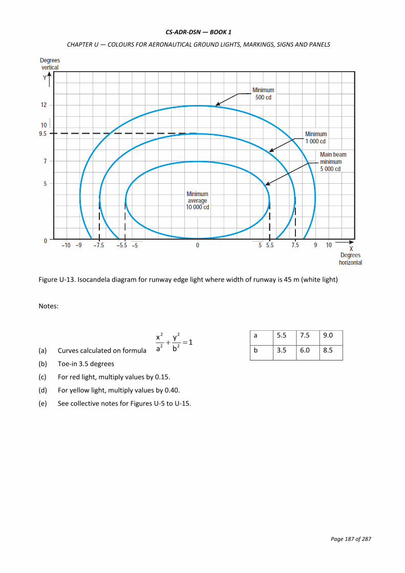
CS-ADR-DSN — BOOK 1
CHAPTER U — COLOURS FOR AERONAUTICAL GROUND LIGHTS, MARKINGS, SIGNS AND PANELS
Page 187 of 287
Figure U-13. Isocandela diagram for runway edge light where width of runway is 45 m (white light)
Notes:
(a) Curves calculated on formula 1
b
y
a
x2
2
2
2
(b) Toe-in 3.5 degrees
(c) For red light, multiply values by 0.15.
(d) For yellow light, multiply values by 0.40.
(e) See collective notes for Figures U-5 to U-15.
a 5.5 7.5 9.0
b 3.5 6.0 8.5

CS-ADR-DSN — BOOK 1
CHAPTER U — COLOURS FOR AERONAUTICAL GROUND LIGHTS, MARKINGS, SIGNS AND PANELS
Page 188 of 287
Figure U-14. Isocandela diagram for runway edge light where width of runway is 60 m (white light)
Notes:
(a) Curves calculated on formula 1
b
y
a
x2
2
2
2
(b) Toe-in 4.5 degrees
(c) For red light, multiply values by 0.15.
(d) For yellow light, multiply values by 0.40.
(e) See collective notes for Figures U-5 to U-15.
a 6.5 8.5 10.0
b 3.5 6.0 8.5
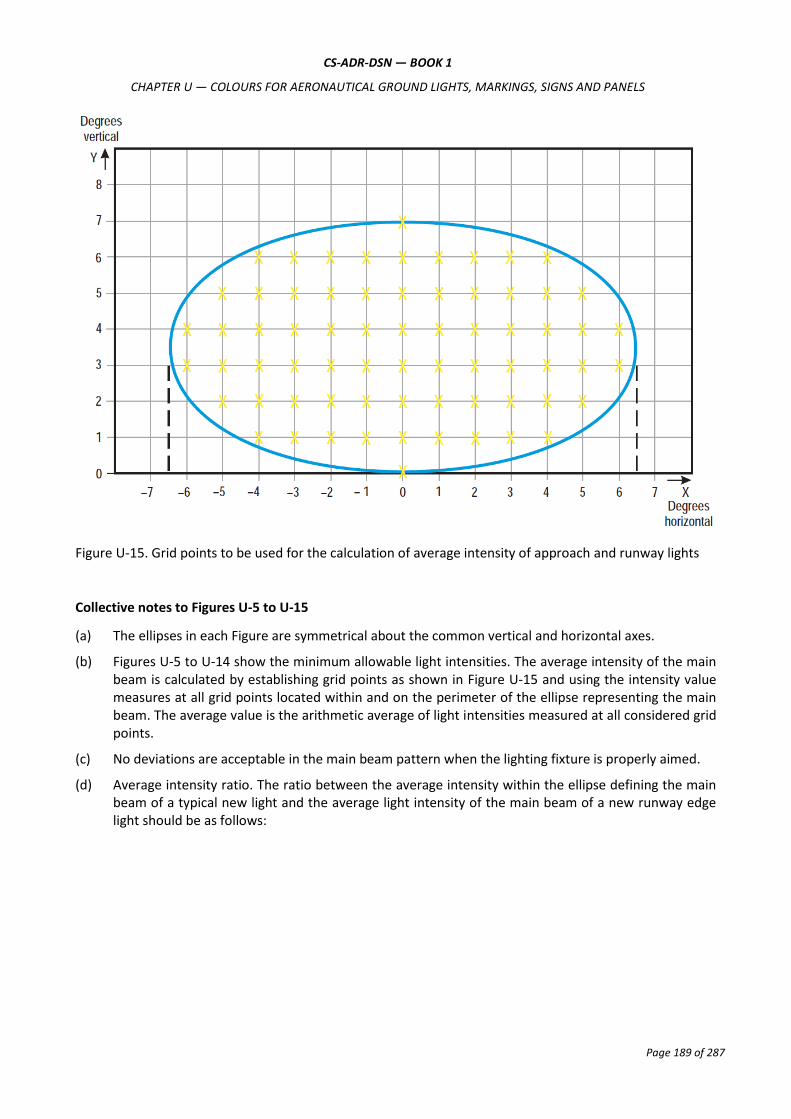
CS-ADR-DSN — BOOK 1
CHAPTER U — COLOURS FOR AERONAUTICAL GROUND LIGHTS, MARKINGS, SIGNS AND PANELS
Page 189 of 287
Figure U-15. Grid points to be used for the calculation of average intensity of approach and runway lights
Collective notes to Figures U-5 to U-15
(a) The ellipses in each Figure are symmetrical about the common vertical and horizontal axes.
(b) Figures U-5 to U-14 show the minimum allowable light intensities. The average intensity of the main beam is calculated by establishing grid points as shown in Figure U-15 and using the intensity value measures at all grid points located within and on the perimeter of the ellipse representing the main beam. The average value is the arithmetic average of light intensities measured at all considered grid points.
(c) No deviations are acceptable in the main beam pattern when the lighting fixture is properly aimed.
(d) Average intensity ratio. The ratio between the average intensity within the ellipse defining the main beam of a typical new light and the average light intensity of the main beam of a new runway edge light should be as follows:

CS-ADR-DSN — BOOK 1
CHAPTER U — COLOURS FOR AERONAUTICAL GROUND LIGHTS, MARKINGS, SIGNS AND PANELS
Page 190 of 287
Figure U-5 Approach centre line and
crossbars
1.5 to 2.0 (white light)
Figure U-6 Approach side row 0.5 to 1.0 (red light)
Figure U-7 Threshold 1.0 to 1.5 (green light)
Figure U-8 Threshold wing bar 1.0 to 1.5 (green light)
Figure U-9 Touchdown zone 0.5 to 1.0 (white light)
Figure U-10 Runway centre line
(longitudinal spacing 30
m)
0.5 to 1.0 (white light)
Figure U-11 Runway centre line
(longitudinal spacing 15
m)
0.5 to 1.0
for CAT III
(white light)
0.25 to 0.5
for CAT I, II
(white light)
Figure U-12 Runway end 0.25 to 0.5 (red light)
Figure U-13 Runway edge (45 m
runway width)
1.0 (white light)
Figure U-14 Runway edge (60 m
runway width)
1.0 (white light)
(e) The beam coverages in the Figures provide the necessary guidance for approaches down to an RVR of the order of 150 m and take-offs down to an RVR of the order of 100 m.
(f) Horizontal angles are measured with respect to the vertical plane through the runway centre line. For lights other than centre line lights, the direction towards the runway centre line is considered positive. Vertical angles are measured with respect to the horizontal plane.
(g) Where, for approach centre line lights and crossbars and for approach side row lights, inset lights are used in lieu of elevated lights, e.g. on a runway with a displaced threshold, the intensity requirements can be met by installing two or three fittings (lower intensity) at each position.
(h) The importance of adequate maintenance cannot be overemphasised. The average intensity should never fall to a value less than 50 % of the value shown in the Figures, and it should be the aim of aerodrome operator to maintain a level of light output close to the specified minimum average intensity.
(i) The light unit should be installed so that the main beam is aligned within one-half degree of the specified.

CS-ADR-DSN — BOOK 1
CHAPTER U — COLOURS FOR AERONAUTICAL GROUND LIGHTS, MARKINGS, SIGNS AND PANELS
Page 191 of 287
Figure U-16. Isocandela diagram for taxiway centre line (15 m spacing) and stop bar lights in straight sections intended for use in runway visual range conditions of less than a value of 350 m where large offsets can occur and for low-intensity runway guard lights, Configuration B
Notes:
(a) These beam coverages allow for displacement of the cockpit from the centre line up to distances of the order of 12 m and are intended for use before and after curves.
(b) See collective notes for Figures U-16 to U-25.
(c) Increased intensities for enhanced rapid exit taxiway centre line lights are four times the respective intensities in the figure (i.e. 800 cd for minimum average main beam).
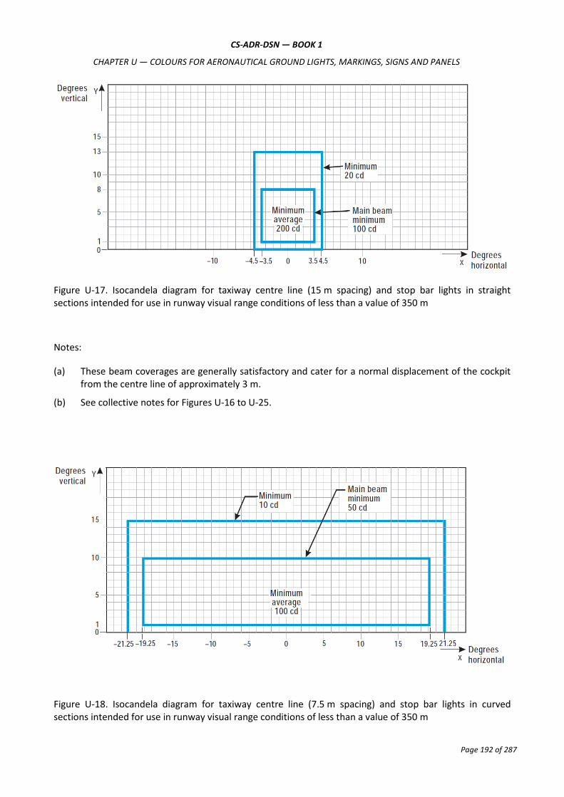
CS-ADR-DSN — BOOK 1
CHAPTER U — COLOURS FOR AERONAUTICAL GROUND LIGHTS, MARKINGS, SIGNS AND PANELS
Page 192 of 287
Figure U-17. Isocandela diagram for taxiway centre line (15 m spacing) and stop bar lights in straight sections intended for use in runway visual range conditions of less than a value of 350 m
Notes:
(a) These beam coverages are generally satisfactory and cater for a normal displacement of the cockpit from the centre line of approximately 3 m.
(b) See collective notes for Figures U-16 to U-25.
Figure U-18. Isocandela diagram for taxiway centre line (7.5 m spacing) and stop bar lights in curved sections intended for use in runway visual range conditions of less than a value of 350 m

CS-ADR-DSN — BOOK 1
CHAPTER U — COLOURS FOR AERONAUTICAL GROUND LIGHTS, MARKINGS, SIGNS AND PANELS
Page 193 of 287
Notes:
(a) Lights on curves to be toed-in 15.75 degrees with respect to the tangent of the curve.
(b) See collective notes for Figures U-16 to U-25.
Figure U-19. Isocandela diagram for taxiway centre line (30 m, 60 m spacing) and stop bar lights in straight sections intended for use in runway visual range conditions of 350 m or greater
Notes:
(a) At locations where high background luminance is usual, and where deterioration of light output resulting from dust, snow, and local contamination is a significant factor, the cd-values should be multiplied by 2.5.
(b) Where omnidirectional lights are used they should comply with the vertical beam requirements in this Figure.
(c) See collective notes for Figures U-16 to U-25.

CS-ADR-DSN — BOOK 1
CHAPTER U — COLOURS FOR AERONAUTICAL GROUND LIGHTS, MARKINGS, SIGNS AND PANELS
Page 194 of 287
Figure U-20. Isocandela diagram for taxiway centre line (7.5 m, 15 m, 30 m spacing) and stop bar lights in curved sections intended for use in runway visual range conditions of 350 m or greater
Notes:
(a) Lights on curves to be toed-in 15.75 degrees with respect to the tangent of the curve.
(b) At locations where high background luminance is usual and where deterioration of light output resulting from dust, snow and, local contamination is a significant factor, the cd-values should be multiplied by 2.5.
(c) These beam coverages allow for displacement of the cockpit from the centre line up to distances of the order of 12 m as could occur at the end of curves.
(d) See collective notes for Figures U-16 to U-25.

CS-ADR-DSN — BOOK 1
CHAPTER U — COLOURS FOR AERONAUTICAL GROUND LIGHTS, MARKINGS, SIGNS AND PANELS
Page 195 of 287
Curve a b c d e
Intensity (cd) 8 20 100 450 1800
Figure U-21. Isocandela diagram for high-intensity taxiway centre line (15 m spacing) and stop bar lights in straight sections intended for use in an advanced surface movement guidance, and control system where higher light intensities are required and where large offsets can occur.
Notes:
(a) These beam coverages are generally satisfactory and cater for a normal displacement of the cockpit corresponding to the outer main gear wheel on the taxiway edge.
(b) See collective notes for Figures U-16 to U-25.

CS-ADR-DSN — BOOK 1
CHAPTER U — COLOURS FOR AERONAUTICAL GROUND LIGHTS, MARKINGS, SIGNS AND PANELS
Page 196 of 287
Curve a b c d e
Intensity (cd) 8 20 100 450 1800
Figure U-22. Isocandela diagram for high-intensity taxiway centre line (15 m spacing) and stop bar lights in straight sections intended for use in an advanced surface movement guidance, and control system where higher light intensities are required
Notes:
(a) These beam coverages are generally satisfactory and cater for a normal displacement of the cockpit corresponding to the outer main gear wheel on the taxiway edge.
(b) See collective notes for Figures U-16 to U-25.

CS-ADR-DSN — BOOK 1
CHAPTER U — COLOURS FOR AERONAUTICAL GROUND LIGHTS, MARKINGS, SIGNS AND PANELS
Page 197 of 287
Curve a b c d
Intensity (cd) 8 100 200 400
Figure U-23. Isocandela diagram for high-intensity taxiway centre line (7.5 m spacing) and stop bar lights in curved sections intended for use in an advanced surface movement guidance, and control system where higher light intensities are required
Notes:
(a) Lights on curves to be toed-in 17 degrees with respect to the tangent of the curve.
(b) See collective notes for Figures U-16 to U-25.

CS-ADR-DSN — BOOK 1
CHAPTER U — COLOURS FOR AERONAUTICAL GROUND LIGHTS, MARKINGS, SIGNS AND PANELS
Page 198 of 287
Figure U-24. Isocandela diagram for high-intensity runway guard lights, Configuration B
Notes:
(a) Although the lights flash in normal operation, the light intensity is specified as if the lights were fixed for incandescent lamps.
(b) See collective notes for Figures U-16 to U-25.
Figure U-25. Grid points to be used for calculation of average intensity of taxiway centre line and stop bar lights
Collective notes to Figures U-16 to U-25:
(a) The intensities specified in Figures U-16 to U-24 are in green and yellow light for taxiway centre line lights, yellow light for runway guard lights, and red light for stop bar lights.

CS-ADR-DSN — BOOK 1
CHAPTER U — COLOURS FOR AERONAUTICAL GROUND LIGHTS, MARKINGS, SIGNS AND PANELS
Page 199 of 287
(b) Figures U-16 to U-24 show the minimum allowable light intensities. The average intensity of the main beam is calculated by establishing grid points as shown in Figure U-25, and using the intensity values measured at all grid points located within and on the perimeter of the rectangle representing the main beam. The average value is the arithmetic average of the light intensities measured at all considered grid points.
(c) No deviations are acceptable in the main beam or in the innermost beam as applicable, when the lighting fixture is properly aimed.
(d) Horizontal angles are measured with respect to the vertical plane through the taxiway centre line, except on curves where they are measured with respect to the tangent to the curve.
(e) Vertical angles are measured from the longitudinal slope of the taxiway surface.
(f) The importance of adequate maintenance cannot be overemphasised. The intensity, either average where applicable or as specified on the corresponding isocandela curves, should never fall to a value less than 50 % of the value shown in the figures, and it should be the aim of aerodrome operator to maintain a level of light output close to the specified minimum average intensity.
(g) The light unit should be installed so that the main beam or the innermost beam as applicable, is aligned within one-half degree of the specified requirement.
Figure U-26. Light intensity distribution of PAPI and APAPI
Notes:
(a) These curves are for minimum intensities in red light.
(b) The intensity value in the white sector of the beam is no less than 2 and may be as high as 6.5 times the corresponding intensity in the red sector.
(c) The intensity values shown in brackets are for APAPI.
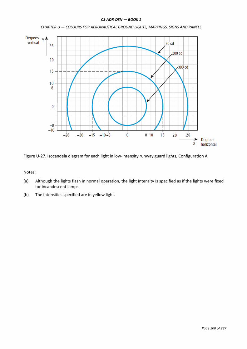
CS-ADR-DSN — BOOK 1
CHAPTER U — COLOURS FOR AERONAUTICAL GROUND LIGHTS, MARKINGS, SIGNS AND PANELS
Page 200 of 287
Figure U-27. Isocandela diagram for each light in low-intensity runway guard lights, Configuration A
Notes:
(a) Although the lights flash in normal operation, the light intensity is specified as if the lights were fixed for incandescent lamps.
(b) The intensities specified are in yellow light.

CS-ADR-DSN — BOOK 1
CHAPTER U — COLOURS FOR AERONAUTICAL GROUND LIGHTS, MARKINGS, SIGNS AND PANELS
Page 201 of 287
Figure U-28. Isocandela diagram for each light in high-intensity runway guard lights, Configuration A
Notes:
(a) Although the lights flash in normal operation, the light intensity is specified as if the lights were fixed for incandescent lamps.
(b) The intensities specified are in yellow light.

Page 202 of 287
CS-ADR-DSN
Book 2
Guidance Material
Aerodromes Design

CS-ADR-DSN — BOOK 2
CHAPTER A — GENERAL
Page 203 of 287
GUIDANCE MATERIAL FOR AERODROMES
CHAPTER A — GENERAL
GM1 ADR-DSN.A.001 Applicability
(a) The certification specifications of Book 1 and the related guidance material contained in Book 2 are
applicable to the aerodromes that fall in the scope of the Commission Regulation (EC) No 216/2008
(Basic Regulation).
(b) At an aerodrome, which falls in the scope of the Basic Regulation and has more than one runway, at
least one runway should meet the criteria contained in Article 4 of the Basic Regulation. However, for
other ‘types’ of runways at aerodrome, it is not compulsory that those runways meet the criteria of
Article 4 of Basic Regulation. Such runways may be Non instrument runways, unpaved runways,
shorten than 800 m runways, runways which are not open to public use or for commercial air
transport. The certification specifications of Book 1 and guidance material of Book 2 are applicable
also to those runways.
GM1 ADR-DSN.A.002 Definitions
Intentionally blank
GM1 ADR-DSN.A.005 Aerodrome Reference Code
(a) The intent of the reference code is to provide a simple method for interrelating the numerous specifications concerning the characteristics of aerodromes so as to provide a series of aerodrome facilities that are suitable for the aeroplanes that are intended to operate at the aerodrome. The code is not intended to be used for determining runway length or pavement strength requirements. The code is composed of two elements which are related to the aeroplane performance characteristics and dimensions.
(b) Element 1 is a number based on the aeroplane reference field length, and element 2 is a letter based on the aeroplane wingspan and outer main gear wheel span. A particular specification is related to the more appropriate of the two elements of the code, or to an appropriate combination of the two code elements. The code letter or number within an element selected for design purposes is related to the critical aeroplane characteristics for which the facility is provided. When applying CS-ADR-DSN text, the aeroplanes which the aerodrome is intended to serve, are first identified and then the two elements of the code.
(c) In addition to the reference code, other aircraft characteristics, such as aircraft length and tail height, may also have an impact on the design of an aerodrome. Additionally, some characteristics of a piece of infrastructure are directly related to one element of the code (wingspan or wheel span) but are not impacted by other. The art of the aerodrome designer should be to consider all the relationships between aircraft characteristics and aerodromes and piece of infrastructures characteristics.
(d) It is not intended that the specifications deriving from the aerodrome reference code limit or regulate the operation of an aircraft.
(e) It is recognised that not all areas of the aerodrome should need to correspond to the critical aircraft that determines the Aerodrome Reference Code. Elements of the aerodrome infrastructure that do

CS-ADR-DSN — BOOK 2
CHAPTER A — GENERAL
Page 204 of 287
not meet the requirements of the Aerodrome Reference Code for the design aircraft should be designated with an appropriate code letter for its dimensions. Limitations should be identified to a/c size permitted or operating limitations. ICAO, Annex 14 does not provide sufficient flexibility for infrastructure intended for different sizes of aircraft. It addresses only the ‘design aircraft’. This enables all areas of the aerodrome to reflect the aerodrome reference code.
GM1 ADR-DSN.A.010
Intentionally blank.

CS-ADR-DSN — BOOK 2
CHAPTER B — RUNWAYS
Page 205 of 287
CHAPTER B — RUNWAYS
GM1 ADR-DSN.B.015 Number, siting, and orientation of runways
(a) In practice the number and orientation of runways at an aerodrome should normally be such that the usability factor of the aerodrome would normally be not less than 95 % for the aeroplanes that the aerodrome is intended to serve.
(b) Many factors affect the determination of the orientation, siting, and number of runways:
(1) The wind distribution (to minimise crosswinds liable to affect runways);
(i) Wind statistics used for the calculation of the usability factor are normally available in ranges of speed and direction, and the accuracy of the results obtained depends, to a large extent, on the assumed distribution of observations within these ranges. In the absence of any sure information as to the true distribution, it is usual to assume a uniform distribution since, in relation to the most favourable runway orientations, this generally results in a slightly conservative usability factor.
(ii) The maximum mean crosswind components given in GM1 ADR-DSN.B.020, refer to normal circumstances. There are some factors which may require that a reduction of those maximum values be taken into account at a particular aerodrome. These include:
A. the wide variations which may exist, in handling characteristics and maximum permissible crosswind components, among diverse types of aeroplanes (including future types) within each of the three groups given in GM1 ADR-DSN.B.020;
B. prevalence and nature of gusts;
C. prevalence and nature of turbulence;
D. the availability of a secondary runway;
E. the width of runways;
F. the runway surface conditions — water, snow, and ice on the runway materially reduce the allowable crosswind component; and
G. the strength of the wind associated with the limiting crosswind component.
(2) The need to facilitate the provision of approaches conforming to the approach surface specifications, ensuring that obstacles in these areas or other factors should not restrict the operation of the aeroplanes for which the runway is intended. This may relate to individual obstacles or local geography (e.g. high ground).
(3) The need to minimise interference with areas approved for residential use and other noise-sensitive areas close to the aerodrome.
(4) The need to avoid the turbulence impacts of buildings on or close to the aerodrome.
(5) Type of operation. Attention should be paid in particular to whether the aerodrome is to be used in all meteorological conditions or only in visual meteorological conditions, and whether it is intended for use by day and night, or only by day.
(6) Topography of the aerodrome site, its approaches, and surroundings, particularly:
(i) compliance with the obstacle limitation surfaces;
CS-ADR-DSN — BOOK 2
CHAPTER B — RUNWAYS
Page 206 of 287
(ii) current and future land use. The orientation and layout should be selected so as to protect as far as possible, the particularly sensitive areas, such as residential, school and hospital zones, from the discomfort caused by aircraft noise. Detailed information on this topic is provided in the ICAO Doc 9184, Airport Planning Manual, Part 2, Land Use and Environmental Control and in ICAO Doc 9829, Guidance on the Balanced Approach to Aircraft Noise Management;
(iii) current and future runway lengths to be provided;
(iv) construction costs; and
(v) possibility of installing suitable non-visual and visual aids for approach-to-land.
(7) Air traffic in the vicinity of the aerodrome, particularly:
(i) proximity of other aerodromes or ATS routes;
(ii) traffic density; and
(iii) air traffic control and missed approach procedures.
(c) The number of runways to be provided in each direction depends on the number of aircraft movements to be catered for.
(d) Whatever the factors that determine the runway orientation, the siting, and orientation of runways at an aerodrome should where possible, be such that safety is optimised.
(e) One important factor is the usability factor, as determined by the wind distribution which is specified hereunder. Another important factor is the alignment of the runway to facilitate the provision of approaches conforming to the approach surface specifications of CS1 ADR-DSN.H.425. In ICAO Annex 14, Attachment A, Section 1, information is given concerning these and other factors. When a new instrument runway is being located, particular attention needs to be given to areas over which aeroplanes should be required to fly when following instrument approach and missed approach procedures so as to ensure that obstacles in these areas or other factors should not restrict the operation of the aeroplanes for which the runway is intended.
GM1 ADR-DSN.B.020 Choice of maximum permissible crosswind components
(a) In the application of GM1 ADR-DSN.B.015 (a) it should be assumed that landing or take-off of aeroplanes is, in normal circumstances, precluded when the crosswind component exceeds:
(1) 37 km/h (20 kt) in the case of aeroplanes whose reference field length is 1 500 m or over, except that when poor runway braking action owing to an insufficient longitudinal coefficient of friction is experienced with some frequency, a crosswind component not exceeding 24 km/h (13 kt) should be assumed;
(2) 24 km/h (13 kt) in the case of aeroplanes whose reference field length is 1 200 m or up to but not including 1 500 m; and
(3) 19 km/h (10 kt) in the case of aeroplanes whose reference field length is less than 1 200 m.
GM1 ADR-DSN.B.025 Data to be used
The selection of data to be used for the calculation of the usability factor should be based on reliable wind distribution statistics that extend over as long a period as possible, preferably of not less than five years. The observations used should be made at least eight times daily and spaced at equal intervals of time.

CS-ADR-DSN — BOOK 2
CHAPTER B — RUNWAYS
Page 207 of 287
GM1 ADR-DSN.B.030 Runway threshold
(a) Additional distance should be provided to meet the requirements of the runway end safety area as appropriate.
(b) Where this displacement is due to an unserviceable runway condition, a cleared and graded area of at least 60 m in length should be available between the unserviceable area and the displaced threshold.
(c) Guidance Material on the survey requirements for aerodromes is provided in the ICAO World Geodetic system – 1984 (WGS-84) Manual, notably in Section 5.3. However, this guidance does not accurately define the survey locations for the runway edge or the runway threshold because, in both cases, the measurement point is not the centre of the relevant paint marking.
(d) Location of threshold:
(1) The threshold is normally located at the extremity of a runway if there are no obstacles penetrating above the approach surface. In some cases, however, due to local conditions it may be desirable to displace the threshold permanently (see below). When studying the location of a threshold, consideration should also be given to the height of the ILS reference datum, and/or MLS approach reference datum, and the determination of the obstacle clearance limits. (Specifications concerning the height of the ILS reference datum and MLS approach reference datum are given in ICAO Annex 10, Volume I.)
(2) In determining that no obstacles penetrate above the approach surface, account should be taken of mobile objects (vehicles on roads, trains, etc.) at least within that portion of the approach area within 1 200 m longitudinally from the threshold and of an overall width of not less than 150 m.
(e) Displaced threshold:
(1) If an object extends above the approach surface and the object cannot be removed, consideration should be given to displacing the threshold permanently.
(2) To meet the obstacle limitation objectives of certification specifications, prescribed in Book 1, Chapter H, the threshold should ideally be displaced down the runway for the distance necessary to provide that the approach surface is cleared of obstacles.
(3) However, displacement of the threshold from the runway extremity should inevitably cause reduction of the landing distance available, and this may be of greater operational significance than penetration of the approach surface by marked and lighted obstacles. A decision to displace the threshold, and the extent of such displacement, should, therefore, have regard to an optimum balance between the considerations of clear approach surfaces and adequate landing distance. In deciding this question, account should need to be taken of the types of aeroplanes which the runway is intended to serve, the limiting visibility and cloud base conditions under which the runway should be used, the position of the obstacles in relation to the threshold and extended centre line, and, in the case of a precision approach runway, the significance of the obstacles to the determination of the obstacle clearance limit.
(4) Notwithstanding the consideration of landing distance available, the selected position for the threshold should not be such that the obstacle-free surface to the threshold is steeper than 3.3 % where the code number is 4 or steeper than 5 % where the code number is 3.
(5) In the event of a threshold being located according to the criteria for obstacle-free surfaces in the preceding paragraph, the obstacle marking requirements of Chapter 6 should continue to be met in relation to the displaced threshold.

CS-ADR-DSN — BOOK 2
CHAPTER B — RUNWAYS
Page 208 of 287
(6) Depending on the length of the displacement, the RVR at the threshold could differ from that at the beginning of the runway for take-offs. The use of red runway edge lights with photometric intensities lower than the nominal value of 10 000 cd for white lights increases that phenomenon.
GM1 ADR-DSN.B.035 Actual length of the runway and declared distances
(a) Length of the runway:
(1) This specification does not necessarily mean providing for operations by the critical aeroplane at its maximum mass.
(2) Both take-off and landing requirements need to be considered when determining the length of runway to be provided and the need for operations to be conducted in both directions of the runway.
(3) Local conditions that may need to be considered include elevation, temperature, runway slope, humidity, and the runway surface characteristics.
(4) When performance data on aeroplanes for which the runway is intended, are not known, guidance on the determination of the actual length of a primary runway by application of general correction factors is given in the ICAO Doc 9157, Aerodrome Design Manual, Part 1, Runways.
(5) Except as provided in GM1 ADR-DSN.B.040, the actual runway length to be provided for a runway should be adequate to meet the operational requirements of the aeroplanes for which the runway is intended, and should be not less than the longest length determined by applying the corrections for local conditions to the operations and performance characteristics of the relevant aeroplanes.

CS-ADR-DSN — BOOK 2
CHAPTER B — RUNWAYS
Page 209 of 287
Figure GM-B-1. Illustration of declared distances
GM1 ADR-DSN.B.040 Runways with stopways, or clearways
Where a runway is associated with a stopway or clearway, an actual runway length less than that resulting from application of GM1 ADR-DSN.B.035 as appropriate, may be considered satisfactory but, in such a case,

CS-ADR-DSN — BOOK 2
CHAPTER B — RUNWAYS
Page 210 of 287
any combination of runway, stopway, and clearway provided should permit compliance with the operational requirements for take-off and landing of the aeroplanes the runway is intended to serve.
GM1 ADR-DSN.B.045 Width of runways
(a) The combinations of code numbers and letters for which widths are specified have been developed for typical aeroplane characteristics.
(b) Factors affecting runway width are given in the ICAO Doc 9157, Aerodrome Design Manual, Part 1, Runways.
GM1 ADR-DSN.B.050 Minimum distance between parallel non-instrument runways
(a) Except that for independent parallel approaches, combinations of minimum distances and associated conditions other than those specified in the PANS-ATM (Doc 4444) may be applied when it is determined that such combinations would not adversely affect the safety of aircraft operations.
(b) Procedures for wake turbulence categorisation of aircraft and wake turbulence separation minima are contained in the Procedures for Air Navigation Services — Air Traffic Management (PANS-ATM), Doc 4444, Chapter 4, 4.9 and Chapter 5, 5.8, respectively.
GM1 ADR-DSN.B.055 Minimum distance between parallel instrument runways
Intentionally blank
GM1 ADR-DSN.B.060 Longitudinal slopes on runways
The slopes on a runway are intended to prevent the accumulation of water (or possible fluid contaminant) on the surface and to facilitate rapid drainage of surface water (or possible fluid contaminant). The water (or possible fluid contaminant) evacuation is facilitated by an adequate combination between longitudinal and transverse slopes, and may also be assisted by grooving the runway surface. Slopes should be so designed as to minimise impact on aircraft and so not to hamper the operation of aircraft. For precision approach runways, slopes in a specified area from the runway end, and including the touchdown area, should be designed so that they should correspond to the characteristics needed for such type of approach.
GM1 ADR-DSN.B.065 Longitudinal slopes changes on runways
(a) Slope changes are so designed as to reduce dynamic loads on the undercarriage system of the aeroplane. Minimising slope changes is especially important on runways where aircraft move at high speeds.
(b) For precision approach runways, slopes in a specified area from the runway end, and including the touchdown area, are so designed that they should correspond to the characteristics needed for such type of approach.
GM1 ADR-DSN.B.070 Sight distance
Runway longitudinal slopes and slopes changes are so designed that the pilot in the aircraft has an unobstructed line of sight over all or as much of the runway as possible, thereby enabling him to see aircraft or vehicles on the runway, and to be able to manoeuvre and take avoiding action.

CS-ADR-DSN — BOOK 2
CHAPTER B — RUNWAYS
Page 211 of 287
GM1 ADR-DSN.B.075 Distance between slope changes on runways
The following example illustrates how the distance between slope changes is to be determined (see Figure
GM-B-2):
D for a runway where the code number is 3 should be at least:
15 000 (│x – y│ + │y – z│) m
│x – y│ being the absolute numerical value of x – y
│y – z│ being the absolute numerical value of y – z
Assuming x = +0.01
Assuming y = –0.005
Assuming z = +0.005
then │x – y│ = 0.015
then │y – z│ = 0.01
To comply with the specifications, D should be not less than:
that is, 15 000 (0.015 + 0.01) m,
that is, 15 000 × 0.025 = 375 m
When a runway is planned that should combine the extreme values for the slopes and changes in slope permitted, as prescribed in CS ADR-DSN.B.060 to CS ADR-DSN.B.080, a study should be made to ensure that the resulting surface profile should not hamper the operation of aeroplanes.
Figure GM-B-2. Profile on centre line of runway
GM1 ADR-DSN.B.080 Transverse slopes on runways
Intentionally blank

CS-ADR-DSN — BOOK 2
CHAPTER B — RUNWAYS
Page 212 of 287
GM1 ADR-DSN.B.085 Runway strength
(a) Pavement forming part of the movement area needs to be of sufficient strength to allow aircraft to operate without risk of damage either to the pavement or to the aircraft. Pavements subject to overload conditions should deteriorate at an increasing rate depending upon the degree of overload. To control this, it is necessary to classify both pavement and aircraft under a system whereby the load-bearing capacity of the pavement and the loads imposed by the aircraft can be compared. The method used is the Aircraft Classification Number - Pavement Classification Number (ACN/PCN) method. The ACN/PCN method has been developed by ICAO as an international method of reporting the bearing strength of pavements.
(b) All pavements forming part of the movement area should be of adequate bearing strength for the types of aircraft expected to use the aerodrome. All pavements should be regularly examined by a suitably qualified person. Any pavements which have been subjected to overload conditions should be closely monitored by suitably qualified staff for a period of several weeks or until it is clear that no rapid deterioration of the pavement has been triggered.
(c) Reporting pavement bearing strength:
(1) The ACN/PCN method of classifying the bearing strength of pavements considers the load imposed on the pavement by the aircraft. In this respect, the load rating of the aircraft is most significantly affected by the subgrade support strength of the pavement. ACNs are, therefore, numbers giving a relative load rating of the aircraft on pavements for certain specified subgrade strengths. ACN values for most aeroplanes have been calculated by ICAO and are published in Aeronautical Information Publications. The PCN is also a number which represents the load-bearing strength of the pavement in terms of the highest ACN which can be accepted on the pavement for unrestricted use.
(2) A PCN can also be identified and reported without a technical evaluation of the pavement by means of an assessment of the results of aircraft using the pavement. Providing the type and subgrade support strength of the pavement are known, the ACN of the most demanding aircraft successfully using the pavement can be reported as the PCN.
(3) A PCN is reported in a five-part format. Apart from the numerical value, notification is also required of the pavement type (rigid or flexible) and the subgrade support category. Additionally, provision is made for the aerodrome operator to limit the maximum allowable tire pressure. A final indication is whether the assessment has been made by a technical evaluation or from past experience of aircraft using the pavement.
(d) Overload operations
(1) Overloading of pavements can result either from loads too large, or from a substantially increased application rate, or both. Loads larger than the defined (design or evaluation) load shorten the design life, whilst smaller loads extend it. With the exception of massive overloading, pavements in their structural behaviour are not subject to a particular limiting load above which they suddenly or catastrophically fail. Behaviour is such that a pavement can sustain a definable load for an expected number of repetitions during its design life. As a result, occasional minor overloading is acceptable, when expedient, with only limited loss in pavement life expectancy and relatively small acceleration of pavement deterioration. For those operations in which magnitude of overload and/or the frequency of use do not justify a detailed analysis, the following criteria are suggested:
(i) for flexible pavements, occasional movements by aircraft with ACN not exceeding 10 % above the reported PCN should not adversely affect the pavement;
(ii) for rigid or composite pavements in which a rigid pavement layer provides a primary

CS-ADR-DSN — BOOK 2
CHAPTER B — RUNWAYS
Page 213 of 287
element of the structure, occasional movements by aircraft with ACN not exceeding 5 % above the reported PCN should not adversely affect the pavement, and
(iii) if the pavement structure is unknown, the 5 % limitation should apply; and
(iv) the annual number of overload movements should not exceed approximately 5 % of the total annual aircraft movements.
(e) Such overload movements should not normally be permitted on pavements exhibiting signs of distress or failure. Furthermore, overloading should be avoided during any periods of thaw following frost penetration, or when the strength of the pavement or its subgrade could be weakened by water. Where overload operations are conducted, the relevant pavement condition should be reviewed regularly. Also the criteria for overload operations should be reviewed periodically since excessive repetition of overloads can cause severe shortening of pavement life or require major rehabilitation of pavement. Further information is contained in the ICAO Doc 9157, Aerodrome Design Manual, Part 3, Pavements.
GM1 ADR-DSN.B.090 Surface of runways
(a) In adopting tolerances for runway surface irregularities, a good engineering practice is that: except across the crown of a camber or across drainage channels, the finished surface of the wearing course is to be of such regularity that when tested with a 3 m straight-edge placed anywhere in any direction on the surface, there is no deviation greater than 3 mm between the bottom of the straight-edge and the surface of the pavement anywhere along the straight-edge.
(b) Caution should also be exercised when inserting runway lights or drainage grilles in runway surfaces to ensure that adequate smoothness of the surface is maintained.
SECTION 1 — RUNWAY TURN PADS
GM1 ADR-DSN.B.095 Runway turn pads
Where severe weather conditions and resultant lowering of surface friction characteristics prevail, a larger wheel-to-edge clearance of 6 m should be provided where the code letter is E or F
Figure GM B-3. Typical turn pad layout
CS-ADR-DSN — BOOK 2
CHAPTER B — RUNWAYS
Page 214 of 287
GM1 ADR-DSN.B.100 Slopes on runway turn pads
Slopes should be so designed as to minimise impact on aircraft and so not to hamper the operation of aircraft.
GM1 ADR-DSN.B.105 Strength of runway turn pads
Intentionally blank
GM1 ADR-DSN.B.110 Surface of runway turn pads
Intentionally blank
GM1 ADR-DSN.B.115 Width of shoulders for runway turn pads
As a minimum, the width of the shoulders would need to cover the outer engine of the most demanding aircraft and thus may be wider than the associated runway shoulders.
GM1 ADR-DSN.B.120 Strength of shoulders for runway turn pads
Intentionally blank

CS-ADR-DSN — BOOK 2
CHAPTER B — RUNWAYS
Page 215 of 287
SECTION 2 — RUNWAY SHOULDERS
GM1 ADR-DSN.B.125 Runway shoulders
(a) Runway shoulders should be so prepared as to be capable of supporting the aeroplanes using the runway without causing structural damage to those aeroplanes. They should also be capable of supporting vehicles such as firefighting appliances. In some cases, whilst the bearing strength of the natural ground may be sufficient, special preparation may be necessary to avoid erosion and the possible ingestion of debris by engines.
(b) Runway shoulders are required because strong crosswinds may result in significant deviation from the runway centre line. As a result, with some large aircraft the wing-mounted engines may overhang the runway edge and there is then a risk of jet blast eroding the surface adjacent to the runway. This can cause dust and the possible ingestion of debris by the engines.
(c) However, for runways where the code letter is D, there may be circumstances where the shoulder need not be paved. Where the runway is not used by 4-engined aircraft, it may be possible to contain the risk from erosion or the ingestion of debris in the absence of paved shoulders. In such cases:
(1) The ground should be prepared so that there is full grass coverage with no loose gravel or other material. This may include additional materials if the bearing strength and surface of the ground are not sufficient.
(2) A programme of inspections of the shoulders and runway may be implemented to confirm its continuing serviceability, and ensure that there is no deterioration that could create a risk of FOD, or otherwise hazard aircraft operations.
(3) A programme of sweeping may be required before and after movements, should debris be drawn onto the runway surface.
(4) If movements of 4-engined aircraft with a code letter D or larger take place, the need for full paved width shoulders should be assessed by local hazard analysis.
The runway shoulder width may be reduced if the width of the runway and the configuration of the aircraft so permit, and confirmed by safety assessment. Further guidance is given in ICAO Doc 9157, Aerodrome Design Manual, Part 1, Runways).
(d) Guidance on characteristics and treatment of runway shoulders:
(1) The shoulder of a runway or stopway should be prepared or constructed so as to support an aeroplane and minimise any hazard to an aeroplane running off the runway or stopway. Some guidance is given in the following paragraphs on certain special problems which may arise, and on the further question of measures to avoid the ingestion of loose stones or other objects by turbine engines.
(2) In some cases, the bearing strength of the natural ground in the strip may be sufficient, without special preparation, to meet the requirements for shoulders. Where special preparation is necessary, the method used should depend on local soil conditions and the mass of the aeroplanes the runway is intended to serve. Soil tests should help in determining the best method of improvement (e.g. drainage, stabilisation, surfacing and light paving).
(e) Attention should also be paid when designing shoulders to prevent the ingestion of stones or other objects by turbine engines. Similar considerations apply here to those which are discussed for the margins of taxiways both as to the special measures which may be necessary and as to the distance over which such special measures if required, should be taken. Further guidance is given in the ICAO

CS-ADR-DSN — BOOK 2
CHAPTER B — RUNWAYS
Page 216 of 287
Doc 9157, Aerodrome Design Manual, Part 1 Runways and Part 2, Taxiways, Aprons and Holding Bays.
(f) Where shoulders have been treated specially, either to provide the required bearing strength or to prevent the presence of stones or debris, difficulties may arise because of a lack of visual contrast between the runway surface and that of the adjacent strip. This difficulty can be overcome either by providing a good visual contrast in the surfacing of the runway or strip, or by providing a runway side stripe marking.
(g) Possible additional mitigation measures could be to provide the runway with inset runway edge lights (in lieu of elevated lights, to protect aeroplane from ingestion) and additional runway centre line guidance.
GM1 ADR-DSN.B.130 Slopes on runway shoulders
Intentionally blank
GM1 ADR-DSN.B.135 Width of runway shoulders
Intentionally blank
GM1 ADR-DSN.B.140 Strength of runway shoulders
Guidance on strength of runway shoulders is given in the ICAO, Doc 9157, Aerodrome Design Manual Part 1, Runways.
GM1 ADR-DSN.B.145 Surface of runway shoulders
(a) Where a runway shoulder is not paved, additional surface treatment or inspections may be necessary, especially for runways that accept operations by 4-engined aircraft with a code letter D or larger.
(b) Shoulders for runways where the code letter is E or F normally should be paved.
(c) For runways where the code letter is F, a reduced paved width of shoulder may be accepted if an safety assessment indicates that such reduction would not affect the safety of operations of aircraft. The minimum paved width should be 60 m. Where a reduced paved width of 60 m is accepted the outer unpaved 7.5 m of runway shoulder should be stabilised and the ground is prepared so that there is full grass coverage with no loose gravel or other material. This may include additional materials if the bearing strength and surface of the ground are not sufficient.
SECTION 3 — RUNWAY STRIP
GM1 ADR-DSN.B.150 Runway strip to be provided
Intentionally blank
GM1 ADR-DSN.B.155 Length of runway strip
Intentionally blank

CS-ADR-DSN — BOOK 2
CHAPTER B — RUNWAYS
Page 217 of 287
GM1 ADR-DSN.B.160 Width of runway strip
Intentionally blank

CS-ADR-DSN — BOOK 2
CHAPTER B — RUNWAYS
Page 218 of 287
GM1 ADR-DSN.B.165 Objects on runway strips
Within the general area of the strip adjacent to the runway, measures should be taken to prevent an aeroplane’s wheel when sinking into the ground, from striking a hard vertical face. Special problems may arise for runway light fittings or other objects mounted in the strip or at the intersection with a taxiway or another runway. In the case of construction, such as runways or taxiways, where the surface should also be flush with the strip surface, a vertical face can be eliminated by chamfering from the top of the construction to not less than 30 cm below the strip surface level. Other objects, the functions of which do not require them to be at surface level, should be buried to a depth of not less than 30 cm. Where this is not feasible, to eliminate a buried vertical surface, a slope should be provided which extends from the top of the construction to not less than 30 cm below ground level. The slope should be no greater than 1:10.
GM1 ADR-DSN.B.170
Intentionally blank
GM1 ADR-DSN.B.175 Grading of runway strips
For a precision approach runway, it may be desirable to adopt a greater width where the code number is 3 or 4. Figure GM B-4 shows the shape and dimensions of a wider strip that may be considered for such a runway. This strip has been designed using information on aircraft running off runways. The portion to be graded extends to a distance of 105 m from the centre line, except that the distance is gradually reduced to 75 m from the centre line at both ends of the strip, for a length of 150 m from the runway end.
Figure GM B-4. Graded portion of a strip including a precision approach runway where the code number is 3 or 4
GM1 ADR-DSN.B.180 Longitudinal Slopes on runway strips
Intentionally blank
GM1 ADR-DSN.B.185 Transverse slopes on runway strips
Intentionally blank

CS-ADR-DSN — BOOK 2
CHAPTER B — RUNWAYS
Page 219 of 287
GM1 ADR-DSN.B.190 Strength of runway strips
Since the graded portion of a strip is provided to minimise the hazard to an aircraft running off the runway, it should be graded in such a manner as to prevent the collapse of the landing gear of the aircraft. The surface should be prepared in such a manner as to provide drag to an aircraft and below the surface, it should have sufficient bearing strength to avoid damage to the aircraft. To meet these divergent needs, the following guidelines are provided for preparing the strip. It is noted, that a depth of 15 cm is a depth to which the nose gear may sink without collapsing. Therefore, it is recommended that the soil at a depth of 15 cm below the finished strip surface should be prepared to have a sufficient stability, demonstrated by bearing strength of California Bearing Ratio (CBR) value of 15 to 20. There are also other technical systems for soil investigation. In case of a deeper sinking than 15 cm, the maximum wheel sinking without collapsing should be examined by using different technical systems of soil investigation. The intention of this is to prevent the nose gear from damage. The top 15 cm may be of lesser strength which would facilitate deceleration of aircraft.
SECTION 4 — CLEARWAYS, STOPWAYS AND RADIO ALTIMETER OPERATING AREA
GM1 ADR-DSN.B.195 Clearways
(a) Because of transverse or longitudinal slopes on a runway, shoulder, or strip, in certain cases, the lower limit of the clearway plane specified above may be below the corresponding elevation of the runway, shoulder, or strip. It is not intended that these surfaces be graded to conform with the lower limit of the clearway plane, nor is it intended that terrain or objects which are above the clearway plane beyond the end of the strip, but below the level of the strip be removed unless it is considered that they may endanger aeroplanes.
(b) Abrupt upward changes in slope should be avoided when the slope on the ground in a clearway is relatively small or when the mean slope is upward. In such situations, in that portion of the clearway within a distance of 22.5 m or half the runway width whichever is greater, on each side of the extended centre line, the slopes, slope changes, and the transition from runway to clearway should generally conform with those of the runway with which the clearway is associated.
(c) The decision to provide a stopway and/or a clearway as an alternative to an increased length of runway should depend on the physical characteristics of the area beyond the runway end, and on the operating performance requirements of the prospective aeroplanes. The runway, stopway, and clearway lengths to be provided are determined by the aeroplane take-off performance but a check should also be made of the landing distance required by the aeroplanes using the runway to ensure that adequate runway length is provided for landing. The length of a clearway, however, cannot exceed half the length of take-off run available.
(d) The aeroplane performance operating limitations require a length which is enough to ensure that the aeroplane can, after starting a take-off, either be brought safely to a stop or complete the take-off safely. For the purpose of discussion, it is supposed that the runway, stopway and clearway lengths provided at the aerodrome are only just adequate for the aeroplane requiring the longest take-off and accelerate-stop distances, taking into account its take-off mass, runway characteristics, and ambient atmospheric conditions. Under these circumstances there is, for each take-off, a speed, called the decision speed; below this speed, the take-off should be abandoned if an engine fails while above it the take-off should be completed. A very long take-off run and take-off distance would be required to complete a take-off when an engine fails before the decision speed is reached because of the insufficient speed and the reduced power available. There would be no difficulty in stopping in the remaining accelerate-stop distance available provided action is taken immediately. In these circumstances the correct course of action would be to abandon the take-off.
CS-ADR-DSN — BOOK 2
CHAPTER B — RUNWAYS
Page 220 of 287
(e) On the other hand if an engine fails after the decision speed is reached, the aeroplane should have sufficient speed and power available to complete the take-off safely in the remaining take-off distance available. However, because of the high speed, there would be difficulty in stopping the aeroplane in the remaining accelerate-stop distance available.
(f) The decision speed is not a fixed speed for any aeroplane but can be selected by the pilot within limits to suit the accelerate-stop and take-off distance available, aeroplane take-off mass, runway characteristics, and ambient atmospheric conditions at the aerodrome. Normally, a higher decision speed is selected as the accelerate-stop distance available increases.
(g) A variety of combinations of accelerate-stop distances required and take-off distances required can be obtained to accommodate a particular aeroplane, taking into account the aeroplane take-off mass, runway characteristics, and ambient atmospheric conditions. Each combination requires its particular length of take-off run.
(h) The most familiar case is where the decision speed is such that the take-off distance required is equal to the accelerate-stop distance required; this value is known as the balanced field length. Where stopway and clearway are not provided, these distances are both equal to the runway length. However, if landing distance is for the moment ignored, runway is not essential for the whole of the balanced field length, as the take-off run required is, of course, less than the balanced field length. The balanced field length can, therefore, be provided by a runway supplemented by an equal length of clearway and stopway, instead of wholly as a runway. If the runway is used for take-off in both directions, an equal length of clearway and stopway has to be provided at each runway end. The saving in runway length is, therefore, bought at the cost of a greater overall length.
(i) In case economic considerations preclude the provision of stopway and, as a result, only runway and clearway are to be provided, the runway length (neglecting landing requirements) should be equal to the accelerate-stop distance required or the take-off run required whichever is greater. The take-off distance available should be the length of the runway plus the length of clearway.
(j) The minimum runway length and the maximum stopway or clearway length to be provided may be determined as follows, from the data in the aeroplane flight manual for the aeroplane considered to be critical from the viewpoint of runway length requirements:
(1) If a stopway is economically possible, the lengths to be provided are those for the balanced field length. The runway length is the take-off run required or the landing distance required whichever is greater. If the accelerate-stop distance required is greater than the runway length so determined, the excess may be provided as stopway, usually at each end of the runway. In addition, a clearway of the same length as the stopway should also be provided;
(2) If a stopway is not to be provided, the runway length is the landing distance required, or if it is greater, the accelerate-stop distance required, which corresponds to the lowest practical value of the decision speed. The excess of the take-off distance required over the runway length may be provided as clearway, usually at each end of the runway.
(k) In addition to the above consideration, the concept of clearways in certain circumstances can be applied to a situation where the take-off distance required for all engines operating exceeds that required for the engine failure case.
GM1 ADR-DSN.B.200 Stopways
(a) The transition from one slope to another should be accomplished by a curved surface with a rate of change not exceeding:
(1) 0.3 % per 30 m (minimum radius of curvature of 10 000 m) where the code number is 3 or 4; and
CS-ADR-DSN — BOOK 2
CHAPTER B — RUNWAYS
Page 221 of 287
(2) 0.4 % per 30 m (minimum radius of curvature of 7 500 m) where the code number is 1 or 2.
(b) The friction characteristics of an unpaved stopway should not be substantially less than that of the runway with which the stopway is associated.
(c) The economy of a stopway can be entirely lost if, after each usage, it should be regraded and compacted. Therefore, it should be designed to withstand at least a certain number of loadings of the aeroplane which the stopway is intended to serve without inducing structural damage to the aeroplane. Notwithstanding that a stopway may have a paved surface, it is not intended that PCN Figures need to be developed for a stopway. Further guidance may be found in ICAO Doc 4444, PANS-OPS.
GM1 ADR-DSN.B.205 Radio altimeter operating area
(a) In order to accommodate aeroplanes making auto-coupled approaches and automatic landings (irrespective of weather conditions), it is desirable that slope changes be avoided or kept to a minimum, on a rectangular area at least 300 m long before the threshold of a precision approach runway. The area should be symmetrical about the extended centre line, 120 m wide. When special circumstances so warrant, the width may be reduced to no less than 60 m if an safety assessment indicates that such reduction would not affect the safety of operations of aircraft. This is desirable because these aeroplanes are equipped with a radio altimeter for final height and flare guidance, and when the aeroplane is above the terrain immediately prior to the threshold, the radio altimeter should begin to provide information to the automatic pilot for auto-flare. Where slope changes cannot be avoided, the rate of change between two consecutive slopes should not exceed 2 % per 30 m.
(b) The inclusion of detailed specifications for radio altimeter operating area in this GM is not intended to imply that a radio altimeter operating area has to be provided.
(c) With a radio altimeter operating area in the pre-threshold area of a precision approach runway the margin to calculate the decision altitude should be smaller and the usability of the adjacent runway may be enhanced.
(d) Further guidance on radio altimeter operating area is given in Manual of All-Weather Operations, (ICAO, Doc 9365, Section 5.2). Guidance on the use of radio altimeter is given in the ICAO, PANS-OPS, Volume II, Part II, Section 1.

CS-ADR-DSN — BOOK 2
CHAPTER C — RUNWAY END SAFETY AREA
Page 222 of 287
CHAPTER C — RUNWAY END SAFETY AREA
GM1 ADR-DSN.C.210 Runway end safety areas
(a) General
(1) A runway end safety area should provide an area long and wide enough, and suitable to contain overruns and undershoots resulting from a reasonably probable combination of adverse operational factors. On a precision approach runway, the ILS localiser is normally the first upstanding obstacle, and the runway end safety area should extend up to this facility. In other circumstances and on a non-precision approach runway, the first upstanding obstacle may be a road, a railroad, or other constructed or natural feature. In such circumstances, the runway end safety area should extend as far as the obstacle.
(2) Whatever length of RESA is provided, it is important to ensure that likelihood of, and potential impacts arising from an overrun are minimised as far as reasonably practicable.
(3) It is recognised that achieving the recommended distance could present challenges. Therefore, the aim of this guidance is to identify the types of aerodrome activities that can be undertaken to reduce the likelihood and consequences of an overrun occurring, and to decide on appropriate actions and it is suggested that aerodrome operators assess their RESA provisions.
(4) The overrun is a complex risk to assess because there are a number of variables, such as prevailing weather, type of aeroplane, the landing aids available, runway characteristics and available distances, the surrounding environment, and human factors. Each of these can have a significant contribution to the overall hazard; furthermore, the nature of the hazard and level of risk should be different for each aerodrome and even for each runway direction at any one aerodrome. The aerodrome may address some, and these are included below. Additionally, aircraft operating procedures may impact but the aerodrome may have little ability to influence these. This should not prevent aerodromes from working with aircraft operators so that the operations are conducted so as to minimise the likelihood of an overrun occurring.
(5) Noting the requirement for a runway end safety area (RESA) consideration should be given to providing an area long enough to contain overruns and undershoots resulting from a reasonably probable combination of adverse operational factors. Therefore, aerodromes should try to maximise the length of RESA available on all applicable runways. When considering the RESA distance required for individual circumstances, aerodromes operators should take into account factors, such as:
(i) the runway length and slope, in particular the general operating lengths required for take-off and landing versus the runway distances available, including the excess of available length over that required;
(ii) current RESA provision (length & width – how much the RESA complies with the recommended distance) and options to increase or improve this;
(iii) the nature and location of any hazard beyond the runway end, including the topography and obstruction environment in and beyond the RESA and outside the runway strip;
(iv) the type of aeroplane and level of traffic at the aerodrome, and actual or proposed changes to either;
(v) aircraft performance limitations arising from runway and RESA length – high performance aircraft, operating at high loads and speeds have greater length requirements than smaller,

CS-ADR-DSN — BOOK 2
CHAPTER C — RUNWAY END SAFETY AREA
Page 223 of 287
low-performance aircraft, the relationship between required balanced field length and available distances;
(vi) navigation aids available (PBN, instrument or visual - if an ILS is only available on one runway direction, a downwind approach and landing may be necessary in poor weather) and the availability of vertical guidance ;
(vii) friction and drainage characteristics of the runway, which impact on runway susceptibility to surface contamination and aeroplane braking action;
(viii) traffic density, which may lead to increased pressure to vacate so increased speed;
(ix) aerodrome weather patterns, including wind shear;
(x) aerodrome overrun history; and
(xi) overrun/undershoot causal factors.
(b) Assessment of runway end safety areas
(1) The RESA assessment should help the aerodrome operator identify the hazards and appropriate actions to reduce the risk. A range of measures may be available, singly or in combination, to reduce the risks of an overrun occurring or becoming an accident. Measures aimed at reducing the likelihood of an overrun/undershoot include:
(i) improving runway surfaces and friction measurement, particularly when the runway is contaminated — know your runways and their condition and characteristics in precipitation;
(ii) ensuring that accurate and up-to-date information on weather, the runway state and characteristics, is notified and passed to flight crews in a timely way, particularly when flight crews need to make operational adjustments;
(iii) improving an aerodrome management’s knowledge, recording, prediction and dissemination of wind data, including wind shear, and any other relevant weather information, particularly when it is a significant feature of an aerodrome’s weather pattern;
(iv) upgrading visual and instrument landing aids to improve the accuracy of aeroplane delivery at the correct landing position on runways (including the provision of Instrument Landing PBN approach systems, location of aiming point and harmonisation with PAPIs);
(v) formulating, in consultation with aeroplane operators, adverse weather and any other relevant aerodrome operating procedures or restrictions, and promulgating such information appropriately; and
(vi) working with aircraft operators to optimise the operation.
(2) Combined with this, measures may be considered that would reduce the severity of the consequences should an event occur. Wherever practicable, aerodrome operators should seek to optimise the RESA. This may be achieved through a combination of:
(i) relocation, shifting or realignment of the runway — it may be possible to construct additional pavement at the start of take-off end to make more pavement available to retain the declared distances. The start and end of declared distances can be moved towards the downwind (start of take-off) end, thereby retaining the declared distance and creating space for a longer RESA, as shown in GM1 ADR-DSN.B.035;
(ii) in the case where undershoot RESA is limited and the runway has a displaced landing

CS-ADR-DSN — BOOK 2
CHAPTER C — RUNWAY END SAFETY AREA
Page 224 of 287
threshold, examine whether the threshold can be moved (downwind) to increase the RESA and/or runway length;
(iii) reducing runway declared distances in order to provide the necessary RESA may be a viable option where the existing runway length exceeds that required for the existing or projected design aircraft. If the take-off distance required for the critical aircraft operating at the aerodrome is less than the take-off distance available, there may be an opportunity to reduce the relevant runway declared distances;
(iv) increasing the length of a RESA, and/or minimising the obstruction environment in the area beyond the RESA. Means to increase the RESA provision include land acquisition, improvements to the grading, realigning fences or roads to provide additional area;
(v) installing suitably positioned and designed arresting systems, to supplement or as an alternative to a RESA where an equivalent level of safety is demonstrated;
(vi) improving the slopes in the RESA to minimise or remove downward slopes; and
(vii) providing paved RESA with known friction characteristics.
(3) A runway meant for take-off and landing in both directions should have 2 RESAs extending for the required distance beyond the end of the strip extending from the runway end. Depending of the position of the threshold on a runway, the RESA related to the reverse runway should protect aircraft undershooting the threshold. Assessments of overruns and undershoots have shown that the likelihood of an undershoot is approximately four times less than for an overrun. Additionally, the undershoot rate shows that the likelihood of an event is further reduced by the availability of precision approach aids, especially those with vertical guidance. Therefore, on a precision approach runway consideration may include whether to reduce the minimum length of RESA towards the length of the runway strip before the runway.
(4) It is recognised that improving RESAs is often difficult. However, it is important to note that incremental gains should be obtained wherever possible, as any gain is valuable. Therefore, whenever a runway project involves construction, consideration should also be given to improving the RESA.
(5) The above lists are not in any particular order, are not exhaustive, and should complement action by aeroplane operators, designers and aviation regulators.
(6) RESA provision should be considered by the Local Runway Safety Team.
(c) Arresting systems on runway end safety areas
(1) In recent years, recognising the difficulties associated with achieving a standard runway end safety area (RESA) at all aerodromes, research programmes have been undertaken on the use of various materials for arresting systems. Furthermore, research programmes have been undertaken to evaluate and develop arrestor systems using engineered materials (EMAS). This research was driven by the recognition that many runways where natural obstacles, local development, and/or environmental constraints inhibit the provision of RESA (as required by changes to ICAO SARPS in 1999) lead to limited dimension RESAs. Additionally, there had been accidents at some aerodromes where the ability to stop an overrunning aeroplane within the RESA would have prevented major damage to aeroplane and/or injuries to passengers.
(2) The research programmes, as well as evaluation of actual aeroplane overruns into an EMAS installation, have demonstrated that EMAS systems are effective in arresting aeroplane overruns.
(3) EMAS or other arresting system designs should be supported by a validated design method that can predict the performance of the system. The design method should be derived from

CS-ADR-DSN — BOOK 2
CHAPTER C — RUNWAY END SAFETY AREA
Page 225 of 287
field or laboratory tests. Testing may be based either on passage of an actual aircraft or an equivalent single wheel load through a test bed. The design should consider multiple aircraft parameters, including but not limited to allowable aircraft gear loads, gear configuration, tire contact pressure, aircraft centre of gravity, and aircraft speed. The model should calculate imposed aircraft gear loads, g-forces on aircraft occupants, deceleration rates, and stopping distances within the arresting system. Any rebound of the crushed material that may lessen its effectiveness, should also be considered.
(4) Demonstrated performance of an arresting system can be achieved by a validated design method which can predict the performance of the system. The design and performance should be based on the type of aircraft anticipated to use the associated runway that imposes the greatest demand upon the arresting system. The system design should be based on a critical (or design) aircraft which is defined as aircraft using the associated runway that imposes the greatest demand upon the arresting system. This is usually but not always, the heaviest/largest aircraft that regularly uses the runway. Arresting system performance is dependent not only on aircraft weight but landing gear configuration and tire pressure. All configurations should be considered in optimising the arresting system design. The aerodrome operator and arresting system manufacturer should consult regarding the selection of the design aircraft that should optimise the arresting system for a particular aerodrome.
(5) EASA considers that the FAA performance specifications and requirements which have been accepted by the ICAO Aerodromes Panel, provide suitable information for aerodromes considering the installation of EMAS. Therefore, attention is drawn to the documents listed below which give guidance on the requirements and evaluation process used by the FAA:
(i) FAA Advisory Circular 150/5300-13 — ‘Airport Design’;
(ii) FAA Advisory Circular 150/5220-22A — ‘Engineered Materials Arresting Systems (EMAS) for Aeroplane Overruns’;
(iii) FAA Order 5200.8 — ‘Runway Safety Area Program’;
(iv) FAA Order 5200.9 — ‘EMAS Financial Feasibility and Equivalency’.
(6) The presence of an arresting system should be published in the AIP entry and information/instructions promulgated to local runway safety teams and others to promote awareness in the pilot community.
(7) Additional information is given in the ICAO Doc 9157, Aerodrome Design Manual, Part 1, Runways.
GM1 ADR-DSN.C.215 Dimensions of runway end safety areas
It is accepted that many aerodromes were constructed before requirements for RESAs were introduced. For applicable runways where the RESA does not extend to the recommended distance, as part of their Safety Management System, aerodromes should assess the risk and implement appropriate and suitable mitigation measures as necessary.
GM1 ADR-DSN.C.220 Objects on runway end safety areas
Information regarding siting of equipment and installations on operational areas, including RESA, is detailed in CS ADR-DSN.T.915.

CS-ADR-DSN — BOOK 2
CHAPTER C — RUNWAY END SAFETY AREA
Page 226 of 287
GM1 ADR-DSN.C.225 Clearing and grading of runway end safety areas
(a) The surface of the runway end safety area should be prepared but does not need to be prepared to the same quality as the runway strip.
(b) Guidance on Clearing and grading of runway end safety areas is given in the ICAO Doc 9157, Aerodrome Design Manual, Part 1, Runways).
GM1 ADR-DSN.C.230 Slopes on runway end safety areas
Where clearway is provided, the slope on the RESA should be amended accordingly.
GM1 ADR-DSN.C.235 Strength of runway end safety areas
(a) A runway end safety area should be so prepared or constructed as to reduce the risk of damage to an aeroplane undershooting or overrunning the runway, enhance aeroplane deceleration, and facilitate the movement of rescue and firefighting vehicles.
(b) Guidance on the strength of a runway end safety area is given in the GM1 ADR-DSN.B.190 Strength of runway strips and in ICAO Doc 9157, Aerodrome Design Manual, Part 1, Runways).

CS-ADR-DSN — BOOK 2
CHAPTER D — TAXIWAYS
Page 227 of 287
CHAPTER D — TAXIWAYS
GM1 ADR-DSN.D.240 Taxiways general
(a) Taxiways should be provided to permit the safe and expeditious surface movement of aircraft. Sufficient entrance and exit taxiways for a runway should be provided to expedite the movement of aeroplanes to and from the runway and provision of rapid exit taxiways considered when traffic volumes are high.
(b) Design of runway and taxiway infrastructure that either prevents aircraft entering or crossing a runway or mitigates the risk of an aircraft runway incursion collision should be considered both in the development of any new infrastructure and as a retrospective enhancement to existing infrastructure especially in hot-spot areas (areas where risk appraisal or incident data demonstrates a higher risk). This guidance may be considered as part of a runway incursion prevention programme and to help ensure that runway incursion aspects are addressed in any new design proposal.
(c) The initial approach should be to reduce the number of available entrances to the runway, so that the potential for entry to the runway at an unintended location is minimised. Taxiway entry, crossing and runway exit taxiways should be clearly identified and promulgated, using taxiing guidance signs, lighting and pavement markings.
(d) Many aerodromes have more than one runway, notably paired parallel runways (two runways on one side of the terminal apron), which create a difficult problem in that either on arrival or departure an aircraft is required to cross a runway. The potential for runway crossings should be eliminated or at least be as low as reasonably practicable. This may be achieved by constructing a ‘perimeter taxiway’ to enable aircraft to get to the departure runway without either crossing a runway, or conflicting with an approaching or departing aircraft
(e) A perimeter taxiway is ideally designed according to the following criteria:
(1) Sufficient space is required between the landing threshold and the taxiway centreline where it crosses under the approach path, to enable the critical aircraft to pass under the approach without violating the approach surface.
(2) The extent of the jet blast impact of aircraft taking off is considered when determining the location of a perimeter taxiway.
(3) The requirement for RESA, as well as possible interference with the ILS is also taken into account: the perimeter taxiway is located behind the localiser antenna, not between the localiser antenna and the runway, due to the potential for severe ILS disturbance, noting that this is harder to achieve as the distance between the localiser and the runway increases. Likewise, perimeter roads are provided where possible.
(f) Taxiways crossing runways should be provided at low energy locations, preferably at the runway ends. Where runway crossings cannot be eliminated, they should only be done on taxiways at right angles to a runway. This will afford the flight crew an unobstructed view of the runway, in both directions, to confirm that the runway and approach is clear of conflicting traffic before proceeding across.
(g) The runway/taxiway configuration should be ‘regular’, for example with single taxiway entrances; this is especially important for taxiways across runways. Examples of good configuration include:
(h) The main design principles for entry and exit taxiways are :
(1) Taxiways should be perpendicular to the runway centreline if possible.
CS-ADR-DSN — BOOK 2
CHAPTER D — TAXIWAYS
Page 228 of 287
(2) The taxiway angle should be such that the crew of an aircraft at a taxiway holding position (if any) should be able to see an aircraft using or approaching the runway. Where the taxiway angle is such that this clear view, in both directions is not possible, consideration is given to provide a perpendicular portion of the taxiway immediately adjacent to the runway to allow for a full visual scan prior to entering (or crossing).
(3) Rapid exit taxiways are designed to be runway exits. Whilst it may be an operational practice at some airports to allow smaller aircraft the option of departing at a mid-point on the runway from one of these rapid exit taxiways, the geometry of the taxiway/runway intersection does not allow the crew to properly scan the runway in both directions to confirm that there is no conflicting traffic. This practice should thus be eliminated and from the design point of view, all signage and markings should deter any aircraft from using these rapid exit taxiways for any purpose other than what they are designed for (exiting the runway after landing). However, this may be mitigated by the addition of a fillet so that aircraft can manoeuvre to see down the approach. Note that aircraft on an angled taxiway may have a greater likelihood of causing ILS interference.
(4) Limiting the options available to pilots on each entrance or exit helps to avoid confusion. Therefore, avoid dual or multiple taxiway entrances at one location, as Y-shaped connectors present opportunities for runway incursions and for aircraft vacating the runway to enter the wrong taxiway. Limiting the options available to pilots on each entrance or exit helps to avoid confusion.
(5) Runway/taxiway separations should be sufficient to permit space for effective RETs.
(6) Avoid designs which include crossing a runway to access a taxiway.
(7) Provide clear separation between high speed (RET) and taxi speed runway exits; if RETs are provided have a series in a row without other entrances.
(8) Where the aerodrome has more than one runway, ensure that runway ends are not too close together; if this is not possible ensure that they are clearly identified as separated. This may be achieved through visual aids, taxiway design and the taxiway naming convention.
(9) Surface colour should not create confusion:
(i) Have different colours for runway and taxiways.
(ii) Avoid a mix of concrete & asphalt.
(10) Wide taxiway entrances onto runways should be broken up with islands or barriers or painting taxiway edges with continuous edge markings to indicate unusable pavement. Avoid long holding position lines and excess paved areas which reduce the effectiveness of signs and markings. Use standard taxiway widths, suitable for a wide range of aeroplane, including the largest type expected to use the aerodrome.
(11) Avoid multi-taxiway intersections and reduce the number of taxiways at any intersection as far as possible.
(12) As far as practicable, it is preferable to redesign rather than reconfigure or repaint where possible – design errors out and reduce potential for human error.
(13) Consistent design of runway entrances – same visual aids at each, both taxiways and service road accesses.
(14) It is always preferable for safety reasons to have a taxiway parallel to the runway all along the runway, even if capacity constraints do not make it necessary.

CS-ADR-DSN — BOOK 2
CHAPTER D — TAXIWAYS
Page 229 of 287
(i) Aerodrome infrastructure can also be used to support design, whether by the systems installed or by their operating characteristics. Examples include:
(1) Stopbars and runway guard lights should be provided at all entrances, and preferably illuminated H24 and in all weather conditions. Runway incursions do not happen only under restricted visibilities. In fact, more incursions happen when the weather is good.
(2) Avoid confusion between Cat 1 and Cat 3 holding positions. This may be achieved in some circumstances by combining both holding positions.
(j) Guidance on layout of taxiways is given in the ICAO Doc 9157, Aerodrome Design Manual, Part 2, Taxiways, Aprons and Holding Bays).
GM1 ADR-DSN.D.245 Width of taxiways
The width of the taxiway should be measured at the edge of the paved surface, or where the taxiway edge is marked, at the outside edge of the taxiway edge marking.
GM1 ADR-DSN.D.250 Taxiways curves
(a) The location of taxiway centre line markings and lights is specified in CS ADR-DSN.L.555 and CS ADR-DSN.M.710.
(b) Compound curves may reduce or eliminate the need for extra taxiway width.
(c) An example of widening taxiways to achieve the wheel clearance specified is illustrated in Figure GM-D-1. Guidance on the values of suitable dimensions is given in the ICAO Doc 9157, Aerodrome Design Manual, Part 2, Taxiways, Aprons and Holding Bays).

CS-ADR-DSN — BOOK 2
CHAPTER D — TAXIWAYS
Page 230 of 287
Figure GM-D-1 Taxiway curve
GM1 ADR-DSN.D.255 Junction and intersection of taxiways
Consideration should be given to the aeroplane datum length when designing fillets. Guidance on the design of fillets and the definition of the term aeroplane datum length are given in the ICAO Doc 9157, Aerodrome Design Manual, Part 2, Taxiways, Aprons and Holding Bays).
GM1 ADR-DSN.D.260 Taxiway minimum separation distance
(a) Guidance on factors which may be considered in the safety assessment, is given in the ICAO Doc 9157, Aerodrome Design Manual, Part 2, Taxiways, Aprons and Holding Bays.
(b) ILS and MLS installations may also influence the location of taxiways due to interferences to ILS and MLS signals by a taxiing or stopped aircraft. Information on critical and sensitive areas surrounding ILS and MLS installations is contained in ICAO, Annex 10, Volume I, Attachments C and G (respectively).
(c) The separation distances, as prescribed in Table D-1, column 10, do not necessarily provide the capability of making a normal turn from one taxiway to another parallel taxiway. Guidance for this condition is given in the ICAO Doc 9157, Aerodrome Design Manual, Part 2, Taxiways, Aprons and Holding Bays.
(d) The separation distance between the centre line of an aircraft stand taxilane and an object, as prescribed in Table D-1, column (13), may need to be increased when jet exhaust wake velocity may cause hazardous conditions for ground servicing.
Location of taxiway centre line
lights and markings (see
M.710(d)(1) and L.555(b)(1), (b)(2))
Taxiway
width,
(see
D.245(a))
Minimum wheel clearance
(see D.240(a))
The Figure shows an example of taxiway widening to achieve
the specified wheel clearance on taxiway curves (see
D.240(a)).

CS-ADR-DSN — BOOK 2
CHAPTER D — TAXIWAYS
Page 231 of 287
(e) It may be permissible to operate with lower separation distances at an existing aerodrome if a safety assessment indicates that such lower separation distances would not adversely affect the safety or significantly affect the regularity of operations of aeroplanes.
(f) The separation distances, as prescribed in Table D-1, may have to be increased on taxiway curves to accommodate the wing sweep of the critical aeroplane or on dual parallel taxiways when, as for example, used as bypass taxiways.
GM1 ADR-DSN.D.265 Longitudinal slopes on taxiways
Intentionally blank
GM1 ADR-DSN.D.270 Longitudinal slope changes on taxiways
Intentionally blank
GM1 ADR-DSN.D.275 Sight distance of taxiways
Intentionally blank
GM1 ADR-DSN.D.280 Transverse slopes on taxiways
The slopes on a taxiway are intended to prevent the accumulation of water (or possible fluid contaminant) on the surface and to facilitate rapid drainage of surface water (or possible fluid contaminant). Slopes should be so designed as to minimise impact on aircraft and so not to hamper the operation of aircraft.
GM1 ADR-DSN.D.285 Strength of taxiways
Information regarding pavement bearing strength, including the ACN/PCN classification system may be found in GM-ADR-DSN.B.085.
Due consideration being given to the fact that a taxiway should be subjected to a greater density of traffic and as a result of slow moving and stationary aeroplanes, to higher stresses than the runway it serves.
GM1 ADR-DSN.D.290 Surface of taxiways
Intentionally blank
GM1 ADR-DSN.D.295 Rapid exit taxiways
(a) The following guidance applies particularly to rapid exit taxiways. See Figure D-1. The general requirements for taxiways, as prescribed in Book 1 are also applicable to rapid exit taxiways. Guidance on the provision, location and design of rapid exit taxiways is included in the ICAO Doc 9157, Aerodrome Design Manual, Part 2, Taxiways, Aprons and Holding Bays).
(b) The locations of rapid exit taxiways along a runway are based on several criteria described in the ICAO Doc 9157, Aerodrome Design Manual, Part 2, Taxiways, Aprons and Holding Bays), in addition to different speed criteria.
GM1 ADR-DSN.D.300 Taxiways on bridges
If aeroplane engines overhang the bridge structure, protection of adjacent areas below the bridge from engine blast may be required.

CS-ADR-DSN — BOOK 2
CHAPTER D — TAXIWAYS
Page 232 of 287
GM1 ADR-DSN.D.305 Taxiway shoulders
Guidance on characteristics of taxiway shoulders and on shoulder treatment is given in the ICAO Doc 9157, Aerodrome Design Manual, Part 2, Taxiways, Aprons and Holding Bays).
GM1 ADR-DSN.D.310 Taxiway Strip
A taxiway strip should be so prepared or constructed as to minimise hazards arising from differences in load bearing capacity to aeroplanes which the taxiway is intended to serve in the event of an aeroplane accidentally running off the taxiway.
Guidance on characteristics of taxiway strips is given in the ICAO Doc 9157, Aerodrome Design Manual, Part 2, Taxiways, Aprons and Holding Bays).
GM1 ADR-DSN.D.315 Width of taxiway strips
Intentionally blank.
GM1 ADR-DSN.D.320 Objects on taxiway strips
(a) Consideration should be given to the location and design of drains on a taxiway strip to prevent damage to an aeroplane accidentally running off a taxiway. Suitably designed drain covers may be required.
(b) The detailed requirements for siting objects on taxiway strips are in CS ADR-DSN.T.915.
GM1 ADR-DSN.D.325 Grading of taxiway strips
Intentionally blank.
GM1 ADR-DSN.D.330 Slopes on taxiway strips
Intentionally blank.
GM1 ADR-DSN.D.335 Holding bays, runway-holding positions, intermediate holding positions, and road-holding positions
(a) At low levels of aerodrome activity (less than approximately 50 000 annual operations), there is normally little need to make deviations in the departure sequence. However, for higher activity levels, aerodromes with single taxiways and no holding bays or other bypasses provide aerodrome control units with no opportunity to change the sequence of departures once the aircraft have left the apron. In particular, at aerodromes with large apron areas, it is often difficult to arrange for aircraft to leave the apron in such a way that they should arrive at the end of the runway in the sequence required by air traffic services units.
(b) The provision of an adequate number of holding bay spaces or other bypasses, based upon an analysis of the current and near-term hourly aircraft departure demand, should allow a large degree of flexibility in generating the departure sequence.
(c) The space required for a holding bay depends on the number of aircraft positions to be provided, the size of the aircraft to be accommodated, and the frequency of their utilisation. The dimensions should allow for sufficient space between aircraft to enable them to manoeuvre independently.
CS-ADR-DSN — BOOK 2
CHAPTER D — TAXIWAYS
Page 233 of 287
(d) Emergency access roads are not intended for use for the functions of aerodrome service roads. However, they should be provided by different access controls which should be clearly visible for all service ground traffic.
(e) Further guidance is given in ICAO Doc 9157, Aerodrome Design Manual, Part 2, Taxiways, Aprons and Holding Bays) and Procedures for Air Navigation Services — Air Traffic Management (ICAO, Doc 4444).
GM1 ADR-DSN.D.340 Location of holding bays, runway-holding positions, intermediate holding positions, and road-holding positions
(a) Care should be taken so that propeller wash and jet blast from holding aircraft do not interfere with aircraft operations, cause damage to vehicles, or injure people.
(b) Generally, when used to allow flexible departure sequencing, the most advantageous location for a holding bay is adjacent to the taxiway serving the runway end. Other locations along the taxiway are satisfactory for aircraft performing pre-flight checks or engine run-ups, or as a holding point for aircraft awaiting departure clearance.
(c) An aircraft taxiing could endanger aircraft operations when the aircraft is too close to the runway during take-off and landings. It is so advised to check if the aircraft taking off or landing could be hinder. For this OLS and specially approach surfaces, take-off climb surfaces and OFZ are the first aspects to consider. An aircraft taxiing could also endanger aircraft operations when the aircraft location and orientation are so that the aircraft interfere with navaids. It is specific to instrument runways and especially important for precision approach runways. The non-penetration of critical/sensitive areas is the first check.
(d) For all runways, it should be verified that the distance between a holding bay, runway-holding position established at a taxiway/runway intersection or road-holding position and the centre line of a runway is so that a holding aircraft or vehicle should not infringe the approach surface and/or take-off climb surface.
(e) If the affected runway is used under precision approach procedures, it should be also verified that the distance between a holding bay, runway-holding position established at a taxiway/runway intersection or road-holding position and the centre line of a runway is so that a holding aircraft or vehicle should not infringe the obstacle-free zone and the critical/sensitive areas of precision approach navaids (e.g. ILS/MLS).
(f) If a holding bay, runway-holding position or road-holding position for a precision approach runway code number 4 is at a greater elevation compared to the threshold, the distance of 90 m or 107.5 m, as appropriate, specified in Table D-2 could be further increased 5 m for every metre the bay or position is higher than the threshold.
(g) An aircraft taxiing could also endanger aircraft operation when the aircraft is too close to other taxiing aircraft. For this, separation distances or margins between taxiing aircraft or taxiways should be considered.
(h) Further guidance is given in ICAO Doc 9157, Aerodrome Design Manual, Part 2, Taxiways, Aprons and Holding Bays).

CS-ADR-DSN — BOOK 2
CHAPTER D — TAXIWAYS
Page 234 of 287
CHAPTER E — APRONS
GM1 ADR-DSN.E.345 General
Intentionally blank
GM1 ADR-DSN.E.350 Size of aprons
(a) The total apron area should be adequate to permit safe and expeditious handling of aerodrome traffic at its maximum anticipated density.
(b) The amount of area required for a particular apron layout depends upon the following factors:
(1) the size and manoeuvrability characteristics of the aircraft using the apron;
(2) the volume of traffic using the apron;
(3) clearance requirements;
(4) type of ingress and egress to the aircraft stand;
(5) basic terminal layout or other aerodrome use;
(6) aircraft ground activity requirements; and
(7) taxiways and service roads.
(c) Passenger aircraft services that are carried out during the time the aircraft is parked in a stand position include: galley; toilet and potable water service; baggage handling; fuelling; provision of air conditioning, oxygen, electrical power supply and starting air; and aircraft towing. Most of these functions have a vehicle and/or equipment associated with them, or have some type of fixed installation established to conduct these services. (ICAO Doc 9157, Aerodrome Design Manual, Part 2, Taxiways, Aprons and Holding Bays, par. 3.4.6).
(d) Consideration should be given to providing sufficient area on the starboard side of the aircraft to support the level of activity that take place in the turnaround operation (ICAO Doc 9157, Aerodrome Design Manual, Part 2, Taxiways, Aprons and Holding Bays, par. 3.4.6).
GM1 ADR-DSN.E.355 Strength of aprons
(a) Apron pavement protection against fuel: On aircraft stands, pavement surface in bituminous concrete and joints between concrete slabs should be protected from fuel effects.
(b) Fuel on bituminous concrete provokes a disintegration of the concrete which becomes a kind of dark powder. On aircraft stands, it is not rare to have fuel on the pavement surface, due to leakage from aircraft or refuelling devices or due to a wrong move during refuelling. Therefore, if the aircraft stand pavement is in bituminous concrete, a specific protection is considered. Such protection is:
(1) a surface protection consisting in an overlay with a material inert against fuel; or
(2) a product incorporated in the mass of the bituminous concrete during its fabrication, protecting aggregates and binder.
(c) The first solution has the disadvantages to be fragile against stamping effects due to aircraft at the stand but is very useful for existing pavement protection.
(d) Taking into account the stamping due to aircraft at stands and the weakness of bituminous concrete against fuel, the aircraft stand pavements are often in cement concrete, which offers a much better

CS-ADR-DSN — BOOK 2
CHAPTER D — TAXIWAYS
Page 235 of 287
resistance to stamping and to fuel. Nevertheless, joints between cement concrete slabs could be also damaged by fuel. According to the location of such joints regarding aircraft location and refuelling devices location, it is preferable to manufacture such joints in a material resistant to the fuel.
GM1 ADR-DSN.E.360 Slopes on aprons
(a) The design of slopes should direct spilled fuel away from building and apron service areas. Where such slopes are unavoidable, special measures should be taken to reduce the fire hazard resulting from fuel spillage.
(b) Slopes on apron have the same purpose as other pavement slopes, meaning to prevent the accumulation of water (or possible fluid contaminant) on the surface and to facilitate rapid drainage of surface water (or possible fluid contaminant). Nevertheless, the design of the apron, especially for the parts containing airplane stands, should specifically take into account the impact of the slopes on the airplane during its braking at the stand and during its start for departure (with push-back or with its own engines). The aims are, on the one hand, to avoid that an airplane passes its stop point and goes on the service road or to the closest building and on the other hand, to save fuel and optimise the manoeuvrability of the airplane or of the push-back device.
(c) Where the slope limitation of 1 % on the stands cannot be achieved, the slope should be kept as shallow as possible and should be such that the operation of the aircraft and vehicles is not compromised.
GM1 ADR-DSN.E.365 Clearance distances on aircraft stands
(a) Reduced separation at the gate is possible where azimuth guidance by a visual docking guidance system is provided, in combination with additional mitigation measures, such as:
(1) good condition of marking and signage;
(2) maintenance of visual docking systems.
(b) Reduced clearance distances on aircraft stands
(1) On aircraft stands where reduced clearance distances exist, guidance by visual docking guidance system should be provided.
(2) All objects for which reduced clearances apply should be properly marked or lighted (Chapter Q Visual Aids for Denoting Obstacles).
(3) Aircraft stands where reduced clearance distances apply should be identified and the information published in the AIP.
(4) An aircraft stand equipped with a visual docking guidance system should provide the minimum clearance of 4.5 metres between an aircraft using the stand and any adjacent building, aircraft on another stand or other objects.

CS-ADR-DSN — BOOK 2
CHAPTER F — ISOLATED AIRCRAFT PARKING POSITION
Page 236 of 287
CHAPTER F — ISOLATED AIRCRAFT PARKING POSITION
GM1 ADR-DSN.F.370 Isolated aircraft parking position
Care should be taken to ensure that the position is not located over underground utilities, such as gas and aviation fuel and, to the extent feasible, electrical or communication cables. The aerodrome control tower should be advised of an area or areas suitable for the parking of an aircraft.

CS-ADR-DSN — BOOK 2
CHAPTER G — DE-ICING/ANTI-ICING FACILITIES
Page 237 of 287
CHAPTER G — DE-ICING/ANTI-ICING FACILITIES
GM1 ADR-DSN.G.375 General
Combinations of ice, snow and/or standing water may, especially when rain, rain and snow, or snow is falling, produce substances with specific gravities in excess of 0.8. These substances, due to their high water/ice content, should have a transparent rather than a cloudy appearance and, at the higher specific gravities, should be readily distinguishable from slush.
GM1 ADR-DSN.G.380 Location
(a) The de-icing/anti-icing facilities should be so located as to ensure that the holdover time of the anti-icing treatment is still in effect at the end of taxiing, and when take-off clearance of the treated aeroplane is given.
(b) To further maximise departure flow rates for all aeroplanes, the location and size of de-icing/anti-icing facilities should be such that they allow for bypass taxiing during de-icing/anti-icing operations. (ICAO, Doc 9640: — Manual of aircraft ground de-icing/anti-icing operations, paragraph 8.5(e).)
(c) Remote de-icing/anti-icing facilities located near departure runway ends or along taxiways are recommended when taxi times from terminals or off-terminal de-icing/anti-icing locations frequently exceed holdover times.
(d) Remote facilities compensate for changing weather conditions when icing conditions or blowing snow are expected to occur along the taxi-route taken by the aeroplane to the runway meant for take-off.
(e) The de-icing/anti-icing facilities should be so located as to provide for an expeditious traffic flow, perhaps with a bypass configuration, and not require unusual taxiing manoeuvre into and out of the pads.
(f) The jet blast effects caused by a moving aeroplane on other aeroplanes receiving the anti-icing treatment or taxiing behind should have to be taken into account to prevent degradation of the treatment.
GM1 ADR-DSN.G.385 Size of de-icing/anti-icing pads
(a) It is recommended that the aerodrome have facilities with a de-icing/anti-icing capability equivalent to the maximum peak hour departure rate that can be managed by the ATC units during de-icing/anti-icing operations. (ICAO, Doc 9640: Manual of aircraft ground de-icing/anti-icing operations, paragraph 8.3.)
(b) The number of de-icing/anti-icing pads required should be determined based on the meteorological conditions, the type of aeroplanes to be treated, the method of application of de-icing/anti-icing fluid, the type and capacity of the dispensing equipment used, and the volume of traffic and departure flow rates.
(c) An aeroplane de-icing/anti-icing pad consists of:
(1) an inner area for parking of an aeroplane to be treated; and
(2) an outer area for movement of two or more mobile de-icing/anti-icing equipment.
(d) Where more than one de-icing/anti-icing pad is provided, consideration should be given to providing de-icing/anti-icing vehicle movement areas of adjacent pads that do not overlap but are exclusive for

CS-ADR-DSN — BOOK 2
CHAPTER G — DE-ICING/ANTI-ICING FACILITIES
Page 238 of 287
each pad. Consideration should also be given to bypassing of the area by other aeroplanes with the clearances specified in CS ADR-DSN.G.400.
GM1 -ADR-DSN.G.390 Slopes on de-icing/anti-icing pads
It is recommended that the drainage arrangements for the collection and safe disposal of excess de-icing/anti-icing fluids prevent ground water contamination.
GM1 ADR-DSN.G.395 Strength of de-icing/anti-icing pads
Consideration should be given to the fact that the de-icing/anti-icing pad (in common with an apron) should be subjected to a higher density of traffic and, as a result of slow-moving or stationary aircraft, to higher stresses than a runway.
GM1 ADR-DSN.G.400 Clearance distances on a de-icing/anti-icing pad
(a) The separation criteria should take into account the need for individual de-icing/anti-icing pads to provide sufficient maneuvering area around the airplane to allow simultaneous treatment by two or more mobile de-icing/anti-icing vehicles and sufficient non-overlapping space for a vehicle safety zone between adjacent de-icing pads and for other de-icing/anti-icing pads.
(b) The minimum clearance distance of 3.8 m is necessary for the movement of de-icing/anti-icing vehicles round the aircraft.
(c) Where the de-icing/anti-icing facility is located in a non-movement area, the minimum clearance distance can be reduced.

CS-ADR-DSN — BOOK 2
CHAPTER H —OBSTACLE LIMITATIONS SURFACES
Page 239 of 287
CHAPTER H — OBSTACLE LIMITATION SURFACES
GM1 ADR-DSN.H.405 Applicability
(a) The obstacle limitation surfaces define the limits to which objects may project into the airspace. Each surface is related to one or more phases of a flight, and provides protection to aircraft during that phase.
(b) The OLS also help to prevent the aerodromes from becoming unusable by the growth of obstacles around the aerodromes.
(c) The effective utilisation of an aerodrome may be considerably influenced by natural features and man-made constructions outside its boundary. These may result in limitations on the distance available for take-off and landing and on the range of meteorological conditions in which take-off and landing can be undertaken. For these reasons, certain areas of the local airspace should be regarded as integral parts of the aerodrome environment.
(d) Objects which penetrate the obstacle limitation surfaces may in certain circumstances cause an increase in the obstacle clearance altitude/height for an instrument approach procedure or any associated visual circling procedure or have other operational impact on flight procedure design. Criteria for flight procedure design are contained in the Procedures for Air Navigation Services — Aircraft Operations (ICAO, PANS-OPS, Doc 8168).
(e) In ideal circumstances all the surfaces should be free from obstacles but when a surface is infringed, any safety measures required should have regard to:
(1) the nature of the obstacle and its location relative to the surface origin, to the extended centre line of the runway or normal approach and departure paths, and to existing obstructions;
(2) the amount by which the surface is infringed;
(3) the gradient presented by the obstacle to the surface origin;
(4) the type of air traffic at the aerodrome; and
(5) the instrument approach procedures published for the aerodrome.
(f) Safety measures could be as follows:
(1) promulgation in the AIP of appropriate information;
(2) marking and/or lighting of the obstacle;
(3) variation of the runway distances declared as available;
(4) limitation of the use of the runway to visual approaches only;
(5) restrictions on the type of traffic.
(g) In addition to the requirements described in Book 1, Chapter H, it may be necessary to call for other restrictions to development and construction on and in the vicinity of the aerodrome in order to protect the performance of visual and electronic aids to navigation and to ensure that such development does not adversely affect instrument approach procedures and the associated obstacle clearance limits.
GM1 ADR-DSN.H.410 Outer horizontal surface
(a) The outer horizontal surface should extend from the periphery of the conical surface as shown in Figure GM-H-1. An outer horizontal surface is a specified portion of a horizontal plane around an
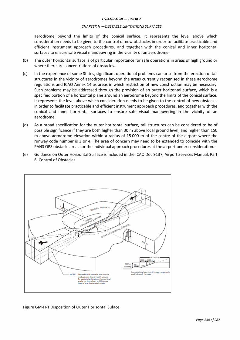
CS-ADR-DSN — BOOK 2
CHAPTER H —OBSTACLE LIMITATIONS SURFACES
Page 240 of 287
aerodrome beyond the limits of the conical surface. It represents the level above which consideration needs to be given to the control of new obstacles in order to facilitate practicable and efficient instrument approach procedures, and together with the conical and inner horizontal surfaces to ensure safe visual manoeuvring in the vicinity of an aerodrome.
(b) The outer horizontal surface is of particular importance for safe operations in areas of high ground or where there are concentrations of obstacles.
(c) In the experience of some States, significant operational problems can arise from the erection of tall structures in the vicinity of aerodromes beyond the areas currently recognised in these aerodrome regulations and ICAO Annex 14 as areas in which restriction of new construction may be necessary. Such problems may be addressed through the provision of an outer horizontal surface, which is a specified portion of a horizontal plane around an aerodrome beyond the limits of the conical surface. It represents the level above which consideration needs to be given to the control of new obstacles in order to facilitate practicable and efficient instrument approach procedures, and together with the conical and inner horizontal surfaces to ensure safe visual maneuvering in the vicinity of an aerodrome.
(d) As a broad specification for the outer horizontal surface, tall structures can be considered to be of possible significance if they are both higher than 30 m above local ground level, and higher than 150 m above aerodrome elevation within a radius of 15 000 m of the centre of the airport where the runway code number is 3 or 4. The area of concern may need to be extended to coincide with the PANS OPS obstacle areas for the individual approach procedures at the airport under consideration.
(e) Guidance on Outer Horizontal Surface is included in the ICAO Doc 9137, Airport Services Manual, Part 6, Control of Obstacles
Figure GM-H-1 Disposition of Outer Horisontal Suface

CS-ADR-DSN — BOOK 2
CHAPTER H —OBSTACLE LIMITATIONS SURFACES
Page 241 of 287
GM1 ADR-DSN.H.415 Conical surface
Intentionally blank
GM1 ADR-DSN.H.420 Inner horizontal surface
(a) The shape of the inner horizontal surface need not necessarily be circular. Guidance on determining the extent of the inner horizontal surface is contained in the ICAO Doc 9137, Airport Services Manual, Part 6, Control of Obstacles.
(b) The limits of the inner horizontal surface for longer runways (1 800 m or more in length) are defined as circles of radius 4 000 m centred on the strip ends of the runway. These circles are joined by common tangents parallel to the runway centre line to form a racetrack pattern. The boundary of this pattern is the boundary of the inner horizontal surface.
(c) For runways less than 1 800 m in length, the inner horizontal surface is defined as a circle centred on the midpoint of the runway.
(d) To protect two or more runways, a more complex pattern could become necessary. In this situation, all the circles are joined tangentially by straight lines: illustrated at the Figure GM-H-2.
(e) For more complex inner horizontal surfaces, with runways on different levels or runways where the thresholds differ more than 6 m, a common elevation is not essential but where surfaces overlap, the lower surface should be regarded as dominant.
(f) Further guidance is contained in the ICAO Doc 9137, Airport Services Manual, Part 6, Control of Obstacles.

CS-ADR-DSN — BOOK 2
CHAPTER H —OBSTACLE LIMITATIONS SURFACES
Page 242 of 287
Figure GM-H-2. Composite inner horizontal surface for two parallel runways (where the runway code is 4)
GM1 ADR-DSN.H.425 Approach surface
Intentionally blank
GM1 ADR-DSN.H.430 Transitional surface
When the elevation of a point on the lower edge is along the strip and equal to the elevation of the nearest point on the centre line of the runway or its extension as a result the transitional surface along the strip should be curved if the runway profile is curved, or a plane if the runway profile is a straight line. The intersection of the transitional surface with the inner horizontal surface should also be a curved or a straight line depending on the runway profile.
GM1 ADR-DSN.H.435 Take-off climb surface
Intentionally blank
GM1 ADR-DSN.H.440 Slewed Take-off climb surface
The edge of a Take-off climb surface may be slewed in the direction of a turn away from the extended runway centre line up to a maximum of 15° splay. The portion of Take-off climb surface encompassing the

CS-ADR-DSN — BOOK 2
CHAPTER H —OBSTACLE LIMITATIONS SURFACES
Page 243 of 287
new departure track should be the same shape and dimensions as the original Take-off climb surface measured relative to the new departure track. The opposite edge of the Take-off climb surface should remain unchanged unless there is another turning departure towards that side as well, in which case, the edge may be slewed in that direction too.
GM1 ADR-DSN.H.445 Obstacle-free zone
Intentionally blank
GM1 ADR-DSN.H.450 Inner approach surface
Intentionally blank
GM1 ADR-DSN.H.455 Inner transitional surface
(a) It is intended that the inner transitional surface be the controlling obstacle limitation surface for navigation aids, aircraft, and other vehicles that should be near the runway, and which is not to be penetrated except for frangible objects. The transitional surface is intended to remain as the controlling obstacle limitation surface for buildings, etc.
(b) The inner transitional surface along the strip should be curved if the runway profile is curved or a plane if the runway profile is a straight line. The intersection of the inner transitional surface with the inner horizontal surface should also be a curved or straight line depending on the runway profile.
GM1 ADR-DSN.H.460 Balked landing surface
Intentionally blank

CS-ADR-DSN — BOOK 2
CHAPTER J —OBSTACLE LIMITATION REQUIREMENTS
Page 244 of 287
CHAPTER J — OBSTACLE LIMITATION REQUIREMENTS
GM1 ADR-DSN.J.465 General
The requirements for obstacle limitation surfaces are specified on the basis of the intended use of a runway, i.e. take-off or landing, and type of approach, and are intended to be applied when such use of the runway is made. In cases where operations are conducted to or from both directions of a runway, the function of certain surfaces may be nullified because of more stringent requirements of another lower surface.
GM1 ADR-DSN.J.470 Non-instrument runways
(a) Circumstances in which the shielding principle may reasonably be applied are described in the ICAO Doc 9137, Airport Services Manual, Part 6, Control of Obstacles.
(b) Because of transverse or longitudinal slopes on a strip, in certain cases the inner edge or portions of the inner edge of the approach surface may be below the corresponding elevation of the strip. It is not intended that the strip be graded to conform with the inner edge of the approach surface, nor is it intended that terrain or objects which are above the approach surface beyond the end of the strip, but below the level of the strip be removed unless it is considered that they may endanger aeroplanes.
GM1 ADR-DSN.J.475 Non-precision approach runways
(a) If it is of particular importance for safe operation on circuits, arrival routes towards the aerodrome or on departure or missed approach climb-paths, an outer horizontal surface for non-precision approach runways should be established.
(b) Circumstances in which the shielding principle may reasonably be applied are described in the ICAO Doc 9137, Airport Services Manual, Part 6, Control of Obstacles.
(c) Because of transverse or longitudinal slopes on a strip, in certain cases the inner edge or portions of the inner edge of the approach surface may be below the corresponding elevation of the strip. It is not intended that the strip be graded to conform with the inner edge of the approach surface, nor is it intended that terrain or objects which are above the approach surface beyond the end of the strip, but below the level of the strip be removed unless it is considered they may endanger aeroplanes.
GM1 ADR-DSN.J.480 Precision approach runways
(a) The following obstacle limitation surfaces should be established for a precision approach runway category I:
(1) inner approach surface;
(2) inner transitional surfaces; and
(3) balked landing surface.
(b) See CS ADR-DSN.T.915 for information regarding siting of equipment and installations on operational areas.
(c) Guidance on obstacle limitation surfaces for precision approach runways is given in the ICAO Doc 9137, Airport Services Manual, Part 6, Control of Obstacles.
CS-ADR-DSN — BOOK 2
CHAPTER J —OBSTACLE LIMITATION REQUIREMENTS
Page 245 of 287
(d) Circumstances in which the shielding principle may reasonably be applied are described in the ICAO Doc 9137, Airport Services Manual, Part 6, Control of Obstacles.
(e) Because of transverse or longitudinal slopes on a strip, in certain cases the inner edge or portions of the inner edge of the approach surface may be below the corresponding elevation of the strip. It is not intended that the strip be graded to conform with the inner edge of the approach surface, nor is it intended that terrain or objects which are above the approach surface beyond the end of the strip, but below the level of the strip, be removed unless it is considered that they may endanger aeroplanes.
(f) For information on code letter F aeroplanes equipped with digital avionics that provide steering commands to maintain an established track during the go-around manoeuvre, see ICAO Circular 301 — New Larger Aeroplanes — Infringement of the Obstacle Free Zone.
GM1 ADR-DSN.J.485 Runways meant for take-off
(a) If no object reaches the 2 % (1:50) take- off climb surface, an obstacle-free surface of 1.6 % (1:62.5) should be established.
(b) When local conditions differ widely from sea level standard atmospheric conditions, it may be advisable for the slope specified in Table J-2 to be reduced. The degree of this reduction depends on the divergence between local conditions and sea level standard atmospheric conditions, and on the performance characteristics and operational requirements of the aeroplanes for which the runway is intended.
(c) Circumstances in which the shielding principle may reasonably be applied are described in the ICAO Doc 9137, Airport Services Manual, Part 6, Control of Obstacles.
(d) Because of transverse slopes on a strip or clearway, in certain cases portions of the inner edge of the take-off climb surface may be below the corresponding elevation of the strip or clearway. It is not intended that the strip or clearway be graded to conform with the inner edge of the take-off climb surface, nor is it intended that terrain or objects which are above the take-off climb surface beyond the end of the strip or clearway, but below the level of the strip or clearway be removed unless it is considered that they may endanger aeroplanes. Similar considerations apply at the junction of a clearway and strip where differences in transverse slopes exist.
(e) The operational characteristics of aeroplanes for which the runway is intended should be examined to see if it is desirable to reduce the slope specified in Table J-2 when critical operating conditions are to be catered to. If the specified slope is reduced, corresponding adjustment in the length of the take-off climb surface should be made so as to provide protection to a height of 300 m.
GM1 ADR-DSN.J.490 Other objects
Intentionally blank

CS-ADR-DSN — BOOK 2
CHAPTER K —VISUAL AIDS FOR NAVIGATION (INDICATORS AND SIGNALLING DEVICES)
Page 246 of 287
CHAPTER K — VISUAL AIDS FOR NAVIGATION (INDICATORS AND SIGNALLING DEVICES)
GM1 ADR-DSN.K.490 Wind direction indicator
(a) Wind direction indicators are important visual aids for all runway ends. Large wind direction indicators are particularly important at aerodromes where landing information is not available through radio communications. On the other hand, landing direction indicators are seldom used due to the necessity and, consequently, responsibility, of changing their direction as wind direction shifts. Visual ground signals for runway and taxiway serviceability are contained in Annex 2. See also ICAO Doc 9157, Aerodrome Design Manual, Part 4, Visual Aids, Chapter 3).
(b) A fabric wind cone is generally the type preferred by pilots because it provides a general indication of wind speed. Cones that extend fully at wind speeds of about 15 kt are most useful since this is the maximum crosswind landing component for small aircraft.
(c) It may be possible to improve the perception by the pilot of the location of the wind direction indicator by several means notably by circular marking around this indicator. The location of at least one wind direction indicator should be marked by a circular band 15 m in diameter and 1.2 m wide. The band should be centred about the wind direction indicator support, and should be in a colour chosen to give adequate conspicuity, preferably white.
(d) The usefulness of any visual aid is determined largely by its size, conspicuity, and location. Given conditions of good atmospheric visibility, the maximum distance at which the information available from an illuminated wind sleeve can be usefully interpreted is 1 km. Thus, in order that a pilot may make use of this information whilst on approach, the wind sleeve should be sited no farther from the runway threshold than 600 m. Obstacle criteria excluded, the ideal location is 300 m along the runway from the threshold and laterally displaced at 80 m from the runway centre line.
(e) This means, in effect, that only those aerodromes where the thresholds are less than 1 200 m apart can meet the minimum requirement with a single unit. Most code 3 and 4 aerodromes should require two or more units suitably sited in order to provide the best possible coverage.
(f) The final choice of unit numbers and location should depend on a number of factors which should vary from aerodrome to aerodrome. However, when deciding on the most appropriate location, account should be taken to ensure that the wind direction indicator is:
(1) outside the Cleared and Graded Area of the runway and taxiway strips;
(2) clear of the OFZ and ILS critical/sensitive areas where appropriate;
(3) preferably not more than 200 m lateral displacement from the runway edge;
(4) preferably between 300 m and 600 m from the runway threshold measured along the runway;
(5) in an area with low background levels of illumination;
(6) visible from the approach and take-off positions of all runways; and
(7) free from the effects of air disturbance caused by nearby objects.

CS-ADR-DSN — BOOK 2
CHAPTER K —VISUAL AIDS FOR NAVIGATION (INDICATORS AND SIGNALLING DEVICES)
Page 247 of 287
GM1 ADR-DSN.K.495 Landing direction indicator
The landing ‘T’ may be constructed of wood or other light material and its dimensions may correspond to those shown in Figure K-1. It may be painted white or orange. The landing ‘T’ should be mounted on a cement concrete pedestal adequately reinforced with steel bars to avoid cracks resulting from unequal settlement. The surface of the pedestal should be finished smooth with a steel trowel and coated with paint of appropriate colour. The colour of the pedestal should be chosen to contrast with the colour of the landing ‘T’. Before fastening the landing ‘T’ base to the concrete pedestal, the mounting bolts should be checked for correct spacing. The landing ‘T’ should be assembled and mounted in accordance with the manufacturer’s installation instructions. It should be free to move about a vertical axis so that it can be set in any direction. Where required for use at night, the landing ‘T’ should either be illuminated or outlined by white lights.
GM1 ADR-DSN.K.500 Signalling lamp
When selecting the green light, use should be made of the restricted boundary of green as specified in GM1 ADR-DSN.U.930(a).
GM1 ADR-DSN.K.505 Signal panels and signal area
(a) A signal panels and signal area should be provided when visual ground signals are used to communicate with aircraft in flight.
(b) A signal panel and signal area may be needed when the aerodrome does not have an aerodrome control tower or an aerodrome flight information service unit, or when the aerodrome is used by aeroplanes not equipped with radio. Visual ground signals may also be useful in the case of failure of two-way radio communication with aircraft. It should be recognised, however, that the type of information which may be conveyed by visual ground signals should normally be available in AIP or NOTAM. The potential need for visual ground signals should, therefore, be evaluated before deciding to provide a signal area.
(c) ICAO Annex 2, Appendix 1, specifies the shape, colour and use of visual ground signals.
GM1 ADR-DSN.K.510 Location of signal panels and signal area
A signal area should be located so as to be visible for all angles of azimuth above an angle of 10° above the horizontal when viewed from a height of 300 m.
GM1 ADR-DSN.K.515 Characteristics of signal panels and signal area
(a) The signal area should be an even horizontal surface at least 9 m square.
(b) The signal area should be constructed of cement concrete reinforced with an adequate quantity of steel to avoid cracks resulting from unequal settlement. The top surface should be finished smooth with a steel trowel and coated with paint of appropriate colour. The colour of the signal area should be chosen to contrast with the colours of the signal panels to be displayed thereon. (More guidance could be find in ICAO Doc 9157, Aerodrome Design Manual Part 4, Visual Aids, Chapter 3).
(c) The colour of the signal area should be chosen to contrast with the colours of the signal panels used, and it should be surrounded by a white border not less than 0.3 m wide.
CS-ADR-DSN — BOOK 2
CHAPTER L —VISUAL AIDS FOR NAVIGATION (MARKINGS)
Page 248 of 287
CHAPTER L — VISUAL AIDS FOR NAVIGATION (MARKINGS)
GM1 ADR-DSN.L.520 General – Colour and conspicuity
(a) Where there is insufficient contrast between the marking and the pavement surface, the marking should include an appropriate border.
(1) This border should be white or black;
(2) It is preferable that the risk of uneven friction characteristics on markings be reduced in so far as practicable by the use of a suitable kind of paint; and
(3) Markings should consist of solid areas or a series of longitudinal stripes providing an effect equivalent to the solid areas.
(4) Guidance on reflective materials is given in the ICAO, Doc 9157, Aerodrome Design Manual, Part 4, Visual Aids.
(b) At aerodromes where operations take place at night, pavement markings should be made with reflective materials designed to enhance the visibility of the markings.
(c) Circumstances may occur when it is not practicable to install permanent markings, for example during runway resurfacing. So as to provide sufficient visual guidance to aircraft, the following markings should be considered:
(1) runway centre line – required for operations below PA Category I;
(2) taxiway centre line lead on/off;
(3) runway edge line;
(4) runway threshold; and
(5) touchdown zone and aiming point markings.
(d) Centre line and edge markings widths can be replaced by reduced width temporary markings and can reduce from 0.9 m to 0.6 m if required.
(e) Touchdown zone and aiming point markings need not be repainted during the same shift as the asphalting but should be done as soon as practicable.
(f) Threshold markings should be returned as soon as possible initially in temporary materials, then permanent materials.
GM1 ADR-DSN.L.525 Runway designation marking
Intentionally blank
GM1 ADR-DSN.L.530 Runway centre line marking
For the centre line marking the 30 m length of and gap between stripes may be adjusted to take into consideration the runway thresholds locations.
GM1 ADR-DSN.L.535 Threshold marking
Intentionally blank

CS-ADR-DSN — BOOK 2
CHAPTER L —VISUAL AIDS FOR NAVIGATION (MARKINGS)
Page 249 of 287
GM1 ADR-DSN.L.540 Aiming point marking
Intentionally blank
GM1 ADR-DSN.L.545 Touchdown zone marking
(a) In order to give information regarding the overall extension of a distance coding touchdown marking, as specified in CS ADR-DSN.L.545, the last pair of markings after the threshold should consist of two single stripes, and the other pairs should correspond to the patterns shown in Figure L-4.
(b) Such sequential layout gives intuitive information about the extension of the touchdown zone and, as a consequence, of the LDA or of the distance between thresholds.
GM1 ADR-DSN.L.550 Runway side stripe marking
When turn pads are not available at the end of a runway for back-track manoeuvres and threshold is displaced, in order to better identify full-strength bearing surface, it may be useful to display specific dashed markings as showed by Figure GM-L-1 and with dimensions described in Table GM-L-1.
GM1 ADR-DSN.L.555 Taxiway centre line marking
The term ‘continuous guidance’ is not intended to require that taxiway centre line markings are provided onto aircraft stands. Instead, it is intended that the centre line marking be provided on taxiways leading to aircraft stands or other apron areas, from which visual cues or other means exist, such as lead-in arrows and stand number indicators, to enable aircrew to manoeuvre the aircraft onto a stand or other parking area.

CS-ADR-DSN — BOOK 2
CHAPTER L —VISUAL AIDS FOR NAVIGATION (MARKINGS)
Page 250 of 287
Figure GM-L-1. Dashed runway side stripe marking
Runway width (m) Single dash dimensions
Length (minimum m) Width (m)
60 15 0.45
45 15 0.45
30 10 0.45
23 6 0.25
18 4 0.25
Table GM-L-1. Runway dashed markings
GM1 ADR-DSN.L.560 Interruption of runway markings
Intentionally blank

CS-ADR-DSN — BOOK 2
CHAPTER L —VISUAL AIDS FOR NAVIGATION (MARKINGS)
Page 251 of 287
GM1 ADR-DSN.L.565 Runway turn pad marking
Intentionally blank
GM1 ADR-DSN.L.570 Enhanced taxiway centre line marking
(a) Enhanced taxiway centre line marking may be provided to denote the proximity of a runway-holding position. The provision of enhanced taxiway centre line marking may form part of runway incursion prevention measures.
(b) Enhanced taxiway centre line marking may be installed at taxiway/runway intersections at that aerodrome as determined by the aerodrome operator/runway safety team as part of the aerodrome’s runway incursion prevention programme.
(c) Those locations where enhanced taxiway centre lines are installed, should be promulgated to AIS and included on the aerodrome chart if required.
GM1 ADR-DSN.L.575 Runway-holding position marking
When the Runway-holding position marking is supplemented with the term ‘CAT II’ or ‘CAT III’ on the areas
or taxiways exceeding 60 m in accordance with CS ADR-DSN.L.575 (a)(6) and should be placed along with
the Mandatory instruction marking in accordance with CS ADR-DSN.L.605 both markings should be equally
and symmetrically placed one next to another.
GM1 ADR-DSN.L.580 Intermediate holding position marking
Intentionally blank
GM1 ADR-DSN.L.585 VOR aerodrome checkpoint marking
Intentionally blank
GM1 ADR-DSN.L.590 Aircraft stand marking
(a) The distances to be maintained between the stop line and the lead-in line may vary according to different aircraft types, taking into account the pilot’s field of view.
(b) Apron markings are installed to support the safe operation of aircraft on stands and apron areas. Where appropriate procedures are employed, markings may not be required, giving flexibility of operations. Examples would include situations where aircraft marshallers are used or where aircraft are required to self-park on an open apron where different combinations of aircraft preclude dedicated markings. Specific markings/stands are normally more applicable for larger aircraft.
GM1 ADR-DSN.L.595 Apron safety lines
Intentionally blank
GM1 ADR-DSN.L.600 Road-holding position marking
(a) Where a road that accesses a runway is unpaved, it may not be possible to install markings. In such cases, a road-holding position signs and/or lights should be installed, combined with appropriate instructions on how the driver of a vehicle should proceed.

CS-ADR-DSN — BOOK 2
CHAPTER L —VISUAL AIDS FOR NAVIGATION (MARKINGS)
Page 252 of 287
(b) Where it is possible to install markings, they should conform to national regulations for traffic sings and markings.
GM1 ADR-DSN.L.605 Mandatory instruction marking
Except where operationally required, a mandatory instruction marking should not be located on a runway.
GM1 ADR-DSN.L.610 Information marking
(a) Applicability: Where operationally required information sign should be supplemented by a marking on the pavement surface.
(b) Location:
(1) An information (location/direction) marking should be displayed prior to and following complex taxiway intersections, and where operational experience has indicated the addition of a taxiway location marking could assist flight crew ground navigation, and on the pavement surface at regular intervals along taxiways of great length.
(2) The information marking should be displayed across the surface of the taxiway or apron where necessary, and positioned so as to be legible from the cockpit of an approaching aircraft.

CS-ADR-DSN — BOOK 2
CHAPTER M —VISUAL AIDS FOR NAVIGATION (LIGHTS)
Page 253 of 287
CHAPTER M — VISUAL AIDS FOR NAVIGATION (LIGHTS)
GM1 ADR-DSN.M.615 General
(a) Aeronautical ground lights near navigable waters should be taken into consideration to ensure that the lights do not cause confusion to mariners.
(b) In dusk or poor visibility conditions by day, lighting can be more effective than marking. For lights to be effective in such conditions or in poor visibility by night, they should be of adequate intensity. To obtain the required intensity, it should usually be necessary to make the light directional, in which case the arcs over which the light shows should be adequate and so orientated as to meet the operational requirements. The runway lighting system should be considered as a whole, to ensure that the relative light intensities are suitably matched to the same end.
(c) While the lights of an approach lighting system may be of higher intensity than the runway lighting, it is good practice to avoid abrupt changes in intensity as these could give a pilot a false impression that the visibility is changing during approach.
(d) The conspicuity of a light depends on the impression received of contrast between the light and its background. If a light is to be useful to a pilot by day when on approach, it should have an intensity of at least 2 000 or 3 000 cd, and in the case of approach lights an intensity of the order of 20 000 cd is desirable. In conditions of very bright daylight fog it may not be possible to provide lights of sufficient intensity to be effective.
(e) On the other hand, in clear weather on a dark night, an intensity of the order of 100 cd for approach lights and 50 cd for the runway edge lights may be found suitable. Even then, owing to the closer range at which they are viewed, pilots have sometimes complained that the runway edge lights seemed unduly bright.
(f) In fog the amount of light scattered is high. At night this scattered light increases the brightness of the fog over the approach area and runway to the extent that little increase in the visual range of the lights can be obtained by increasing their intensity beyond 2 000 or 3 000 cd. In an endeavour to increase the range at which lights would first be sighted at night, their intensity should not be raised to an extent that a pilot might find excessively dazzling at diminished range.
(g) From the foregoing should be evident the importance of adjusting the intensity of the lights of an aerodrome lighting system according to the prevailing conditions, so as to obtain the best results without excessive dazzle that would disconcert the pilot. The appropriate intensity setting on any particular occasion should depend both on the conditions of background brightness and the visibility.
(h) Assessment on dazzle in the aerodrome vicinity:
(1) Human vision is a complex mechanism using both eye and brain. Even though this mechanism is quite handled for eye, there is still a lack of knowledge on the interpretation of it by the brain. Thus, vision varies from one human being to another.
(2) The field of view is defined by the area perceived by eyes. The perception of details is based on the luminance ratio between elements of the scene, taking into account spatial distribution. Luminance and contrast are key elements of vision mechanism.
(3) Four sectors can be identified in the field of view (FOV):
(i) sensation field, corresponding to the absolute boundaries of FOV; it opens up to approximately 90° on each side of the eye direction;

CS-ADR-DSN — BOOK 2
CHAPTER M —VISUAL AIDS FOR NAVIGATION (LIGHTS)
Page 254 of 287
(ii) visibility field, which is narrower and enables the perception of an object; it opens up to 60°;
(iii) conspicuity field, which enables the recognition, it opens up to 30°;
(iv) working conspicuity field, which is further tightly centred on the eye direction (1 to 2°); it enables the identification and is the working area of the vision.
It is reminded that the retina is composed in its centre by cone cells (that see colours and
details) and at the periphery by rod cells (that perceive movements and change of state).
(i) A safety assessment is conducted in order to identify situations where the risk of dazzling becomes unacceptable. Thus, it is noted that dazzle represents such a risk in the following situations:
(1) during approach, especially after the aircraft has descended below the decision height: the pilot should not lose any visual cue;
(2) at touchdown the pilot should not be surprised by a flash;
(3) during rolling (landing or take-off), the pilot should be able to perceive his environment and detect any deviation from the centre line: the pilot should not lose any visual cue.
(4) Thus:
(i) prejudicial dazzle due to veiling luminance should not occur during approach (slightly before the decision height) and rolling; and
(ii) surprise effect should not occur at touchdown.
(j) Regarding air traffic controllers, it has been considered that dazzle induced by veiling effect should not reduce the visual perception of aircraft operations on, and close to the runway.
(k) The elements here above can be applied to solar panels. The following assumptions can be made:
(1) solar panels are inclined so as to efficiently capture the sunlight, conducting to a range of cross section surfaces;
(2) the maximum acceptable luminance value has been fixed to 20 000 cd/m2; and
(3) the surfaces varied from 100 m2 to several hectares.
(l) It is assumed that the aircraft maintains precisely its trajectory whereas in reality the approach is conducted into a conical envelop around the expected trajectory.
GM1 ADR-DSN.M.620 Aeronautical beacons
Intentionally blank

CS-ADR-DSN — BOOK 2
CHAPTER M —VISUAL AIDS FOR NAVIGATION (LIGHTS)
Page 255 of 287
SECTION 1 — APPROACH LIGHTING SYSTEMS
GM1 ADR-DSN.M.625 Approach lighting systems, general and applicability
(a) Types and characteristics
(1) The approach lighting patterns that have been generally adopted are shown in Figures M-1 and M-2. A diagram of the inner 300 m of the precision approach category II and III lighting system is shown in Figures M-3A and M-3B.
(2) The approach lighting configuration is to be provided irrespective of the location of the threshold, i.e. whether the threshold is at the extremity of the runway or displaced from the runway extremity. In both cases, the approach lighting system should extend up to the threshold. However, in the case of a displaced threshold, inset lights are used from the runway extremity up to the threshold to obtain the specified configuration. These inset lights are designed to satisfy the structural requirements specified in CS ADR.DSN.M.615(c)(2) and the chromaticity and characteristics specified in CS ADR-DSN.U.930 and CS ADR-DSN.U.940.
(3) Examples of flight path envelopes used in designing the lighting are shown in Figure GM-M-2.
(b) Horizontal installation tolerances:
(1) The dimensional tolerances are shown in Figure M-1 and M-2.
(2) The centre line of an approach lighting system should be as coincident as possible with the extended centre line of the runway with a maximum tolerance of ±15′.
(3) The longitudinal spacing of the centre line lights should be such that one light (or group of lights) is located in the centre of each crossbar, and the intervening centre line lights are spaced as evenly as practicable, between two crossbars or a crossbar and a threshold.
(4) The crossbars and barrettes should be at right angles to the centre line of the approach lighting system with a tolerance of ±30′ if the pattern in Figure M-2(A) is adopted or ± 2° if Figure M-2(B) is adopted.
(5) When a crossbar has to be displaced from its standard position, any adjacent crossbar should where possible, be displaced by appropriate amounts in order to reduce the differences in the crossbar spacing.
(6) When a crossbar in the system shown in Figure M-2(A) is displaced from its standard position, its overall length should be adjusted so that it remains one-twentieth of the actual distance of the crossbar from the point of origin. It is not necessary, however, to adjust the standard 2.7 m spacing between the crossbar lights but the crossbars should be kept symmetrical about the centre line of the approach lighting.
(c) Vertical installation tolerances:
(1) The ideal arrangement is to mount all the approach lights in the horizontal plane passing through the threshold as shown in Figure GM-M-1, and this should be the general aim as far as local conditions permit. However, buildings, trees, etc. should not obscure the lights from the view of a pilot who is assumed to be 1° below the electronic glide path in the vicinity of the outer marker.
(2) Within a stopway or clearway, and within 150 m of the end of a runway, the lights should be mounted as near to the ground as local conditions permit in order to minimise risk of damage to aeroplanes in the event of an overrun or undershoot. Beyond the stopway and clearway, it

CS-ADR-DSN — BOOK 2
CHAPTER M —VISUAL AIDS FOR NAVIGATION (LIGHTS)
Page 256 of 287
is not so necessary for the lights to be mounted close to the ground, and, therefore, undulations in the ground contours can be compensated for by mounting the lights on poles of appropriate height.
(3) It is desirable that the lights be mounted so that as far as possible, no object within a distance of 60 m on each side of the centre line protrudes through the plane of the approach lighting system. Where a tall object exists within 60 m of the centre line and within 1 350 m from the threshold for a precision approach lighting system, or 900 m for a simple approach lighting system, it may be advisable to install the lights so that the plane of the outer half of the pattern clears the top of the object.
(4) In order to avoid giving a misleading impression of the plane of the ground, the lights should not be mounted below a gradient of 1 in 66 downwards from the threshold to a point 300 m out, and below a gradient of 1 in 40 beyond the 300 m point. For a precision approach category II and III lighting system, more stringent criteria may be necessary, e.g. negative slopes not permitted within 450 m of the threshold.
(i) Centre line. The gradients of the centre line in any section (including a stopway or clearway) should be as small as practicable, and the changes in gradients should be as few and small as can be arranged, and should not exceed 1 in 60. Experience has shown that as one proceeds outwards from the runway, rising gradients in any section of up to 1 in 66, and falling gradients of down to 1 in 40, are acceptable.
(ii) Crossbars. The crossbar lights should be so arranged as to lie on a straight line passing through the associated centre line lights, and wherever possible, this line should be horizontal. It is permissible, however, to mount the lights on a transverse gradient not more than 1 in 80 if this enables crossbar lights within a stopway or clearway to be mounted nearer to the ground on sites where there is a cross-fall.
(5) When the barrette is composed of lights approximating to point sources, a spacing of 1.5 m between adjacent lights in the barrette has been found satisfactory.
(6) At locations where identification of the simple approach lighting system is difficult at night due to surrounding lights, sequence flashing lights installed in the outer portion of the system may resolve this problem.
(d) Clearance of obstacles:
(1) An area, hereinafter referred to as the light plane, has been established for obstacle clearance purposes, and all lights of the system are in this plane. This plane is rectangular in shape and symmetrically located about the approach lighting system’s centre line. It starts at the threshold and extends 60 m beyond the approach end of the system, and is 120 m wide.
(2) No objects are permitted to exist within the boundaries of the light plane which are higher than the light plane except as designated herein. All roads and highways are considered as obstacles extending 4.8 m above the crown of the road, except aerodrome service roads where all vehicular traffic is under control of the aerodrome operator and coordinated with the aerodrome air traffic control. Railroads, regardless of the amount of traffic, are considered as obstacles extending 5.4 m above the top of the rails.
(3) It is recognised that some components of electronic landing aids systems, such as reflectors, antennas, monitors, etc. should be installed above the light plane. Every effort should be made to relocate such components outside the boundaries of the light plane. In the case of reflectors and monitors, this can be done in many instances.
(4) Where an ILS localiser is installed within the light plane boundaries, it is recognised that the localiser, or screen if used, should extend above the light plane. In such cases, the height of

CS-ADR-DSN — BOOK 2
CHAPTER M —VISUAL AIDS FOR NAVIGATION (LIGHTS)
Page 257 of 287
these structures should be held to a minimum and they should be located as far from the threshold as possible. In general, the rule regarding permissible heights is 15 cm for each 30 m the structure is located from the threshold. As an example, if the localiser is located 300 m from the threshold, the screen should be permitted to extend above the plane of the approach lighting system by 10 × 15 = 150 cm maximum but preferably should be kept as low as possible, consistent with proper operation of the ILS.
(5) In locating an MLS azimuth antenna the guidance contained in ICAO Annex 10, Volume I, Attachment G, should be followed. This material which also provides guidance on collocating an MLS azimuth antenna with an ILS localiser antenna, suggests that the MLS azimuth antenna may be sited within the light plane boundaries where it is not possible or practical to locate it beyond the outer end of the approach lighting for the opposite direction of approach. If the MLS azimuth antenna is located on the extended centre line of the runway, it should be as far as possible from the closest light position to the MLS azimuth antenna in the direction of the runway end. Furthermore, the MLS azimuth antenna phase centre should be at least 0.3 m above the light centre of the light position closest to the MLS azimuth antenna in the direction of the runway end. (This could be relaxed to 0.15 m if the site is otherwise free of significant multipath problems.)
(6) Compliance with this requirement which is intended to ensure that the MLS signal quality is not affected by the approach lighting system, could result in the partial obstruction of the lighting system by the MLS azimuth antenna. To ensure that the resulting obstruction does not degrade visual guidance beyond an acceptable level, the MLS azimuth antenna should not be located closer to the runway end than 300 m and the preferred location is 25 m beyond the 300 m crossbar (this would place the antenna 5 m behind the light position 330 m from the runway end). Where an MLS azimuth antenna is so located, a central part of the 300 m crossbar of the approach lighting system would alone be partially obstructed. Nevertheless, it is important to ensure that the unobstructed lights of the crossbar remain serviceable all the time.
(7) Objects existing within the boundaries of the light plane, requiring the light plane to be raised in order to meet the criteria contained herein, should be removed, lowered, or relocated where this can be accomplished more economically than raising the light plane.
(8) In some instances objects may exist which cannot be removed, lowered, or relocated economically. These objects may be located so close to the threshold that they cannot be cleared by the 2 % slope. Where such conditions exist and no alternative is possible, the 2 % slope may be exceeded or a ‘stair step’ resorted to in order to keep the approach lights above the objects. Such ‘step’ or increased gradients should be resorted to only when it is impracticable to follow standard slope criteria, and they should be held to the absolute minimum. Under this criterion no negative slope is permitted in the outermost portion of the system.
(e) Consideration of the effects of reduced lengths:
(1) The need for an adequate approach lighting system to support precision approaches where the pilot is required to acquire visual references prior to landing, cannot be stressed too strongly. The safety and regularity of such operations is dependent on this visual acquisition. The height above runway threshold at which the pilot decides there are sufficient visual cues to continue the precision approach and land, should vary, depending on the type of approach being conducted and other factors such as meteorological conditions, ground and airborne equipment, etc. The required length of approach lighting system which should support all the variations of such approaches is 900 m, and this should always be provided whenever possible.

CS-ADR-DSN — BOOK 2
CHAPTER M —VISUAL AIDS FOR NAVIGATION (LIGHTS)
Page 258 of 287
(2) However, there are some runway locations where it is impossible to provide the 900 m length of approach lighting system to support precision approaches.
(3) In such cases, every effort should be made to provide as much approach lighting system as possible. Restrictions on operations could be imposed on runways equipped with reduced lengths of approach lighting. There are many factors which determine at what height the pilot should have decided to continue the approach to land or execute a missed approach. It should be understood that the pilot does not make an instantaneous judgement upon reaching a specified height. The actual decision to continue the approach and landing sequence is an accumulative process which is only concluded at the specified height. Unless lights are available prior to reaching the decision point, the visual assessment process is impaired and the likelihood of missed approaches should increase substantially. There are many operational considerations which should be taken into account in deciding if any restrictions are necessary to any precision approach and these are detailed in ICAO Annex 6 – Operation of Aircrafts.
(f) For Non precision approach runways it is advisable to give consideration to the installation of a precision approach category I lighting system or to the addition of a runway lead-in lighting system.
Figure GM-M-1. Vertical installation tolerances

CS-ADR-DSN — BOOK 2
CHAPTER M —VISUAL AIDS FOR NAVIGATION (LIGHTS)
Page 259 of 287
Figure GM-M-2. Flight path envelope examples for lighting design for category I, II and III operations - Centre line lights
GM1 ADR-DSN.M.626 Simple approach lighting systems
Intentionally blank

CS-ADR-DSN — BOOK 2
CHAPTER M —VISUAL AIDS FOR NAVIGATION (LIGHTS)
Page 260 of 287
GM1 ADR-DSN.M.630 Precision approach category I lighting system
(a) The installation of an approach lighting system of less than 900 m in length may result in operational limitations on the use of the runway.
(b) Spacings for the crossbar lights between 1 m and 4 m are in use. Gaps on each side of the centre line may improve directional guidance when approaches are made with a lateral error, and facilitate the movement of rescue and firefighting vehicles.
GM1 ADR-DSN.M.635 Precision approach category II and III lighting system
The length of 900 m is based on providing guidance for operations under category I, II and III conditions. Reduced lengths may support category II and III operations but may impose limitations on category I operations. See ICAO Annex 14, Attachment A, Section 11.

CS-ADR-DSN — BOOK 2
CHAPTER M —VISUAL AIDS FOR NAVIGATION (LIGHTS)
Page 261 of 287
SECTION 2 — VISUAL APPROACH SLOPE INDICATOR SYSTEMS
GM1 ADR-DSN.M.640 Visual approach slope indicator systems
(a) Factors that should be considered when making a decision on which runway on an aerodrome should receive first priority for the installation of a visual approach slope indicator system are:
(1) frequency of use;
(2) seriousness of the hazard;
(3) presence of other visual and non-visual aids;
(4) type of aeroplanes using the runway; and
(5) frequency and type of adverse weather conditions under which the runway should be used.
(b) With respect to the seriousness of the hazard, the order given in the CS ADR-DSN.M.640 may be used as a general guide. These may be summarised as:
(1) inadequate visual guidance because of:
(i) approaches over water or featureless terrain, or absence of sufficient extraneous light in the approach area by night;
(ii) deceptive surrounding terrain.
(2) serious hazard in approach;
(3) serious hazard if aeroplanes undershoot or overrun; and
(4) unusual turbulence.
(c) The presence of other visual or non-visual aids is a very important factor. Runways equipped with ILS or MLS would generally receive the lowest priority for a visual approach slope indicator system installation. It should be remembered, though, that visual approach slope indicator systems are visual approach aids in their own right and can supplement electronic aids. When serious hazards exist and/or a substantial number of aeroplanes not equipped for ILS or MLS use a runway, priority might be given to installing a visual approach slope indicator on this runway.
(d) Priority may be given to runways used by turbojet aeroplanes.
(e) Where a runway threshold is temporarily displaced from the normal position and one or more of the
conditions specified in paragraph (a) above exist, a PAPI should be provided except that where the
code number is 1 or 2 either an APAPI may be provided.
GM1 ADR-DSN.M.645 PAPI and APAPI
Intentionally blank

CS-ADR-DSN — BOOK 2
CHAPTER M —VISUAL AIDS FOR NAVIGATION (LIGHTS)
Page 262 of 287
GM1 ADR-DSN.M.650 Approach slope and elevation setting of light units (for PAPI and APAPI)
Intentionally blank
GM1 ADR-DSN.M.655 Obstacle protection surface for PAPI and APAPI
Intentionally blank
GM1 ADR-DSN.M.660 Circling guidance lights
Intentionally blank
SECTION 3 — RUNWAY & TAXIWAY LIGHTS
Intentionally blank
GM1 ADR-DSN.M.665 Runway lead-in lighting systems
(a) Applicability: A runway lead-in lighting system may be provided for purposes of noise abatement
routing.
(b) Characteristics:
(1) Where practicable, the flashing lights in each group should flash in sequence towards the runway.
(2) The path of the system may be segmented, straight, or a combination thereof, as required.
(3) The starting point of the path may be at a point within easy visual range of a final approach fix.
GM1 ADR-DSN.M.670 Runway threshold identification lights
(a) Applicability: Runway threshold identification lights should be installed:
(1) at the threshold of a non-precision approach runway when additional threshold conspicuity is necessary or where it is not practicable to provide other approach lighting aids; and
(2) where a runway threshold is permanently displaced from the runway extremity or temporarily displaced from the normal position and additional threshold conspicuity is necessary.
(b) Characteristics: Runway threshold identification lights should be flashing white lights with a flash frequency between 60 and 120 per minute.
GM1 ADR-DSN.M.675 Runway edge lights
Intentionally blank
GM1 ADR-DSN.M.680 Runway threshold and wing bar lights
Intentionally blank
GM1 ADR-DSN.M.685 Runway end lights
When the threshold is at the runway extremity, fittings serving as threshold lights may be used as runway end lights.

CS-ADR-DSN — BOOK 2
CHAPTER M —VISUAL AIDS FOR NAVIGATION (LIGHTS)
Page 263 of 287
GM1 ADR-DSN.M.690 Runway centre line lights
(a) Runway centre line lights should be provided on a precision approach runway category I when the runway is used by aircraft with high landing speeds or where the width between the runway edge lights is greater than 50 m.
(b) Runway centre line lights should be provided on a runway intended to be used for take-off with an operating minimum of an RVR of the order of 400 m or higher when used by aeroplanes with a very high take-off speed where the width between the runway edge lights is greater than 50 m.
GM1 ADR-DSN.M.695 Runway touchdown zone lights
To allow for operations at lower visibility minima, it may be advisable to use a 30 m longitudinal spacing between barrettes.
GM1 ADR-DSN.M.700 Rapid exit taxiway indicator lights
(a) The purpose of a rapid exit taxiway indicator lights (RETILs) is to provide pilots of a landing aeroplane in the direction of approach to the runway with additional distance-to-go information to the nearest rapid exit taxiway on the runway, to enhance situational awareness in low visibility conditions, and to enable pilots to apply braking action for safe and more efficient roll-out and runway exit speeds.
(b) Applicability:
(1) In low visibility conditions, rapid exit taxiway indicator lights provide useful situational awareness cues while allowing the pilot to concentrate on keeping the aircraft on the runway centre line.
(2) Rapid exit taxiway indicator lights should be considered on a runway intended for use in runway visual range conditions less than a value of 350 m where the traffic density is heavy.
(3) Rapid exit taxiway indicator lights should not be displayed in the event of any lamp failure or other failure that prevents the display of the light pattern depicted in Figure GM-M-3 in full.
(c) Location:
(1) Where provided a set of rapid exit taxiway indicator lights should be located on the runway on the same side of the runway centre line as the associated rapid exit taxiway, in the configuration shown in Figure GM-M-3. In each set, the lights should be located 2 m apart and the light nearest to the runway centre line should be displaced 2 m from the runway centre line.
(2) Where more than one rapid exit taxiway exists on a runway, the set of rapid exit taxiway indicator lights for each exit should not overlap when displayed.
(d) Characteristics:
(1) Rapid exit taxiway indicator lights are fixed lights and comprise a set of yellow unidirectional lights installed in the runway adjacent to the centre line. The lights are positioned in a 3-2-1 sequence at 100 m intervals prior to the point of tangency of the rapid exit taxiway centre line.
(2) Rapid exit taxiway indicator lights should be supplied with power on a separate circuit to other
runway lighting so that they may be used when other lighting is switched off.
(3) Following a landing, runway occupancy time has a significant effect on achievable runway capacity. Rapid exit taxiway indicator lights allow pilots to maintain a good roll-out speed until it is necessary to decelerate to an appropriate speed for the turn into a rapid exit turn-off. A

CS-ADR-DSN — BOOK 2
CHAPTER M —VISUAL AIDS FOR NAVIGATION (LIGHTS)
Page 264 of 287
roll-out speed of 60 kt until the first RETIL (three-light barrette) is reached is seen as the optimum.
(4) Rapid exit taxiway indicator lights should be in accordance with the specifications in Chapter U, as appropriate.
Figure GM-M-3. Rapid exit taxiway indicator lights (RETILs)
GM1 ADR-DSN.M.705 Stopway lights
Intentionally blank
GM1 ADR-DSN.M.710 Taxiway centre line lights
(a) In the case where taxiway centre line lights are provided and where there may be a need to delineate the edges of a taxiway, e.g. on a rapid exit taxiway, narrow taxiway, or in snow conditions, this may be done with taxiway edge lights or markers. Care is necessary to limit the light distribution of green lights on or near a runway so as to avoid possible confusion with threshold lights.
GM1 ADR-DSN.M.715 Taxiway centre line lights on taxiways, runways, rapid exit taxiways, or on other exit taxiways
Intentionally blank

CS-ADR-DSN — BOOK 2
CHAPTER M —VISUAL AIDS FOR NAVIGATION (LIGHTS)
Page 265 of 287
GM1 ADR-DSN.M.720 Taxiway edge lights
Intentionally blank
GM1 ADR-DSN.M.725 Runway turn pad lights
Intentionally blank
GM1 ADR-DSN.M.730 Stop bar lights
(a) Where the normal stop bar lights might be obscured from a pilot’s view, for example, by snow or
rain, or where a pilot may be required to stop the aircraft in a position so close to the lights that they
are blocked from view by the structure of the aircraft, then a pair of elevated lights should be added
to each end of the stop bar.
(b) Where the additional lights specified in (a) above are provided, these lights should be located not
less than 3 m from the taxiway edge.
(c) Where the additional lights specified in (a) above are provided, these lights should have the same
characteristics as the lights in the stop bar but should be visible to approaching aircraft up to the stop
bar position.
GM1 ADR-DSN.M.735 Intermediate holding position lights
Intentionally blank
GM1 ADR-DSN.M.740 De-icing/anti-icing facility exit lights
Intentionally blank
GM1 ADR-DSN.M.745 Runway guard lights
(a) Some other device or design, e.g. specially designed optics, may be used in lieu of the visor.
(b) Higher light intensities may be required to maintain ground movement at a certain speed in low visibilities
(c) The optimum flash rate is dependent on the rise and fall times of the lamps used. Runway guard lights, Configuration A, installed on 6.6 ampere series circuits have been found to look best when operated at 45 to 50 flashes per minute per lamp. Runway guard lights, Configuration B, installed on 6.6 ampere series circuits have been found to look best when operated at 30 to 32 flashes per minute per lamp.
(d) Where there is a need to enhance the contrast between the on- and off-state of runway guard lights, Configuration A, intended for use during the day, a visor of sufficient size to prevent sunlight from entering the lens without interfering with the function of the fixture should be located above each lamp.
SECTION 4 — APRON LIGHTING
CS-ADR-DSN — BOOK 2
CHAPTER M —VISUAL AIDS FOR NAVIGATION (LIGHTS)
Page 266 of 287
GM1 ADR-DSN.M.750 Apron floodlighting
Where a de-icing/anti-icing facility is located in close proximity to the runway and permanent floodlighting could be confusing to pilots, other means of illumination of the facility may be required.
GM1 ADR-DSN.M.755 Visual docking guidance system
(a) The factors to be considered in evaluating the need for a visual docking guidance system are in particular: the number and type(s) of aircraft using the aircraft stand, weather conditions, space available on the apron, and the precision required for manoeuvring into the parking position due to aircraft servicing installation, passenger loading bridges, etc.
(b) Care is required in both the design and on-site installation of the system to ensure that reflection of sunlight, or other light in the vicinity, does not degrade the clarity and conspicuity of the visual cues provided by the system.
GM1 ADR-DSN.M.760 Advanced visual docking guidance system
(a) Advanced visual docking guidance systems should include those systems that, in addition to basic
and passive azimuth, and stop position information, provide pilots with active (usually sensor-based)
guidance information, such as aircraft type indication, distance-to-go information, and closing speed.
Docking guidance information is usually provided in a single display unit.
(b) Advanced visual docking guidance systems should include those systems that, in addition to basic
and passive azimuth, and stop position information, provide pilots with active (usually sensor-based)
guidance information, such as aircraft type indication, distance-to-go information, and closing speed.
Docking guidance information is usually provided in a single display unit.
(c) The use of the Advanced visual docking guidance systems in conditions such as weather, visibility, and background lighting both by day and night would need to be specified.
(d) Care is required in both the design and on-site installation of the system to ensure that glare,
reflection of sunlight, or other light in the vicinity, does not degrade the clarity and conspicuity of the
visual cues provided by the system.
(e) The use of colour needs to be appropriate and should follow signal convention, i.e. red, yellow and
green mean hazard, caution and normal/correct conditions respectively. The effects of colour
contrasts also need to be considered.
(f) The indication of the distance of the aircraft from the stop position may be colour-coded and
presented at a rate and distance proportional to the actual closure rate, and distance of the aircraft
approaching the stop point.
GM1 ADR-DSN.M.765 Aircraft stand manoeuvring guidance lights
Intentionally blank
GM1 ADR-DSN.M.770 Road-holding position light
Where a road intersects a taxiway where operationally required, a suitable holding position light may be
located adjacent to the roadway/taxiway intersection marking 1.5 m (±0.5 m) from one edge of the road,
i.e. left or right as appropriate to the local road traffic regulations.

CS-ADR-DSN — BOOK 2
CHAPTER N —VISUAL AIDS FOR NAVIGATION (SIGNS)
Page 267 of 287
CHAPTER N — VISUAL AIDS FOR NAVIGATION (SIGNS)
GM1 ADR-DSN.N.775 General
(a) Signs may need to be orientated to improve readability.
(b) If the runway threshold is displaced from the extremity of the runway, a sign showing the designation of the runway may be provided for aeroplanes taking off.
(c) Guidance on signs is contained in the ICAO Doc 9157, Aerodrome Design Manual, Part 4, Visual Aids, Chapter 11.
(d) Guidance on frangibility is contained in the ICAO Doc 9157, Aerodrome Design Manual, Part 6, Frangibility.
(e) Guidance on measuring the average luminance of a sign is contained in the ICAO Doc 9157,
Aerodrome Design Manual, Part 4, Visual Aids.
GM1 ADR-DSN.N.780 Mandatory instruction signs
Intentionally blank
GM1 ADR-DSN.N.785 Information signs
Intentionally blank
GM1 ADR-DSN.N.790 VOR aerodrome checkpoint sign
Intentionally blank
GM1 ADR-DSN.N.795 Aircraft stand identification signs
Intentionally blank
GM1 ADR-DSN.N.800 Road-holding position sign
Intentionally blank

CS-ADR-DSN — BOOK 2
CHAPTER P —VISUAL AIDS FOR NAVIGATION (MARKERS)
Page 268 of 287
CHAPTER P — VISUAL AIDS FOR NAVIGATION (MARKERS)
GM1 ADR-DSN.P.805 General
Intentionally blank
GM1 ADR-DSN.P.810 Unpaved runway edge markers
Intentionally blank
GM1 ADR-DSN.P.815 Stopway edge markers
Intentionally blank
GM1 ADR-DSN.P.820 Edge markers for snow-covered runways
(a) Characteristics: Runway lights could be used to indicate the limits.
GM1 ADR-DSN.P.825 Taxiway edge markers
(a) At small aerodromes, taxiway edge markers may be used, in lieu of taxiway edge lights, to delineate the edges of taxiways, particularly at night (ICAO Doc 9157, Aerodrome Design Manual, Part 4, Visual Aids, Chapter 2, par. 2.4.1).
(b) On a straight section of a taxiway, taxiway edge markers should be spaced at uniform longitudinal intervals of not more than 60 m. On a curve the markers should be spaced at intervals less than 60 m so that a clear indication of the curve is provided. The markers should be located as near as practicable to the edges of the taxiway, or outside the edges at a distance of not more than 3 m (ICAO Doc 9157, Aerodrome Design Manual, Part 4, Visual Aids, Chapter 2, par. 2.4.2).
(c) The markers commonly used are cylindrical in shape. Ideally, the design of the marker should be such that when installed properly, no portion should exceed 35 cm total height above the mounting surface. However, where significant snow heights are possible, markers exceeding 35 cm in height may be used but their total height should be sufficiently low to preserve clearance for propellers, and for the engine pods of jet aircraft (ICAO Doc 9157, Aerodrome Design Manual, Part 4, Visual Aids, Chapter 2, par. 2.4.4).
(d) A taxiway edge marker should be lightweight and frangible. One type of marker meeting these requirements is detailed in Figure 2-10. The post is made up of flexible PVC and its colour is blue. The sleeve which is retro-reflective, is also blue. Note that the area of the marked surface is 150 cm2 (ICAO Doc 9157, Aerodrome Design Manual, Part 4, Visual Aids, Chapter 2, par. 2.4.5).

CS-ADR-DSN — BOOK 2
CHAPTER P —VISUAL AIDS FOR NAVIGATION (MARKERS)
Page 269 of 287
Figure GM-P-1. Taxiway edge marker
GM1 ADR-DSN.P.830 Taxiway centre line markers
Intentionally blank
GM1 ADR-DSN.P.835 Unpaved taxiway edge markers
Intentionally blank

CS-ADR-DSN — BOOK 2
CHAPTER Q —VISUAL AIDS FOR DENOTING OBSTACLES
Page 270 of 287
CHAPTER Q — VISUAL AIDS FOR DENOTING OBSTACLES
GM1 ADR-DSN.Q.840 Objects to be marked and/or lighted
The marking and/or lighting of obstacles is intended to reduce hazards to aircraft by indicating the presence of the obstacles. It does not necessarily reduce operating limitations which may be imposed by an obstacle.
GM1 ADR-DSN.Q.845 Marking of objects
(a) Orange and white or alternatively red and white are preferably used, except where such colours merge with the background.
(b) Table Q-3 shows a formula for determining band widths, and for having an odd number of bands, thus permitting both the top and bottom bands to be of the darker colour.
(c) Against some backgrounds it may be found necessary to use a different colour from orange or red to obtain sufficient contrast.
(d) A single colour, preferably red or yellowish green for emergency vehicles and yellow for service vehicles, is generally used.
(e) Alternative spacing may be suitable; priority is to highlight the location and definition of the object.
GM1 ADR-DSN.Q.850 Lighting of objects
(a) High-intensity obstacle lights are intended for day use as well as night use. Care is needed to ensure that these lights do not create disconcerting dazzle or environmental concerns. Guidance on the design, location, and operation of high-intensity obstacle lights is given in the ICAO Doc 9157, Aerodrome Design Manual, Part 4, Visual Aids.
(b) Low-intensity obstacle lights may be used, Type A or B for obstacles higher than 45 m if it is determined to be sufficient.
(c) A group of trees or buildings is regarded as an extensive object.
Note.— In some cases, this may require locating the lights off the tower.
(d) Guidance Material on how a combination of low, medium, and/or high-intensity lights on obstacles should be displayed is given in the following Figures:

CS-ADR-DSN — BOOK 2
CHAPTER Q —VISUAL AIDS FOR DENOTING OBSTACLES
Page 271 of 287
Figure GM-Q-1.Medium-intensity flashing-white obstacle lighting system, Type A

CS-ADR-DSN — BOOK 2
CHAPTER Q —VISUAL AIDS FOR DENOTING OBSTACLES
Page 272 of 287
Figure GM-Q-2. Medium-intensity flashing-red obstacle lighting system, Type B

CS-ADR-DSN — BOOK 2
CHAPTER Q —VISUAL AIDS FOR DENOTING OBSTACLES
Page 273 of 287
Figure GM-Q-3. Medium-intensity fixed-red obstacle lighting system, Type c

CS-ADR-DSN — BOOK 2
CHAPTER Q —VISUAL AIDS FOR DENOTING OBSTACLES
Page 274 of 287
Figure GM-Q-4. Medium-intensity dual obstacle lighting system, Type A/Type B

CS-ADR-DSN — BOOK 2
CHAPTER Q —VISUAL AIDS FOR DENOTING OBSTACLES
Page 275 of 287
Figure GM-Q-5. Medium-intensity dual obstacle lighting system, Type A/Type C

CS-ADR-DSN — BOOK 2
CHAPTER Q —VISUAL AIDS FOR DENOTING OBSTACLES
Page 276 of 287
Figure GM-Q-6. High-intensity flashing-white obstacle lighting system, Type A

CS-ADR-DSN — BOOK 2
CHAPTER Q —VISUAL AIDS FOR DENOTING OBSTACLES
Page 277 of 287
Figure GM-Q-7. High-/medium-intensity dual obstacle lighting system, Type A/Type B

CS-ADR-DSN — BOOK 2
CHAPTER Q —VISUAL AIDS FOR DENOTING OBSTACLES
Page 278 of 287
Figure GM-Q-8. High-/medium-intensity dual obstacle lighting system, Type A/Type C
In the cases as stated in CS ADR-DSN.Q.850(c)(7) and (c)(8), normally the spacing would not exceed 52 m.

CS-ADR-DSN — BOOK 2
CHAPTER R —VISUAL AIDS FOR DENOTING RESTRICTED USE AREAS
Page 279 of 287
CHAPTER R — VISUAL AIDS FOR DENOTING RESTRICTED USE AREAS
GM1 ADR-DSN.R.855 Closed runways and taxiways, or parts thereof
Intentionally blank
GM1 ADR-DSN.R.860 Non-load-bearing surfaces
The marking characteristics of runway sides is specified in CS ADR-DSN.L.550.
A taxi side stripe marking could also be placed along the edge of the load-bearing pavement to emphasise the location of the taxiway edge, with the outer edge of the marking approximately on the edge of the load-bearing pavement.
At intersections of taxiways and on other areas where, due to turning, the possibility for confusion between the side stripe markings and centre line markings may exist, or where the pilot may not be sure on which side of the edge marking the non-load bearing pavement is, the additional provision of transverse stripes on the non-load bearing surface has been found to be of assistance.
As shown in Figure GM-R-1, the transverse stripes should be placed perpendicular to the side stripe marking.
On curves, a stripe should be placed at each point of tangency of the curve and at intermediate points along the curve so that the interval between stripes does not exceed 15 m. If deemed desirable to place transverse stripes on small straight sections, the spacing should not exceed 30 m.
The width of the marks should be 0.9 m, and they should extend to within 1.5 m of the outside edge of the stabilised paving or be 7.5 m long whichever is shorter. The colour of the transverse stripes should be the same as that of the edge stripes, i.e. yellow.

CS-ADR-DSN — BOOK 2
CHAPTER R —VISUAL AIDS FOR DENOTING RESTRICTED USE AREAS
Page 280 of 287
Figure GM-R-1. Marking of non-load bearing paved taxiway surface
More guidance on providing additional transverse stripes at an intersection or a small area on the apron is given in the ICAO Doc 9157, Aerodrome Design Manual, Part 4, Visual Aids).
GM1 ADR-DSN.R.865 Pre-threshold area
For pre-threshold areas shorter than 60 m, markings may be modified or reduced in size so as to present the correct picture to aircrew.
GM1 ADR-DSN.R.870 Unserviceable areas
(a) Unserviceability markers and lights are used for such purposes as warning pilots of a hole in a taxiway, or apron pavement, or outlining a portion of pavement, such as on an apron, that is under repair. They are not suitable for use when a portion of a runway becomes unserviceable, nor on a taxiway when a major portion of the width becomes unserviceable. In such instances, the runway or taxiway is normally closed.
(b) The spacing required for marking and lights should take into account visibility conditions, geometric configurations of the area, potential height differences of terrain so that the limits of unserviceable area is readily visible to pilot.

CS-ADR-DSN — BOOK 2
CHAPTER R —VISUAL AIDS FOR DENOTING RESTRICTED USE AREAS
Page 281 of 287
(c) Where a temporarily unserviceable area exists, it may be marked with fixed-red lights. These lights mark the most potentially dangerous extremities of the area.
(d) A minimum of four such lights may be used, except where the area is triangular in shape, in which case a minimum of three lights may be used.
(e) The number of lights may be increased when the area is large or of unusual configuration. At least one light should be installed for each 7.5 m of peripheral distance of the area.
(f) If the lights are directional, they should be orientated so that as far as possible, their beams are aligned in the direction from which aircraft or vehicles should approach.
(g) Where aircraft or vehicles should normally approach from several directions, consideration should be given to adding extra lights or using omnidirectional lights to show the area from these directions.
(h) Unserviceable area lights should be frangible. Their height should be sufficiently low to preserve clearance for propellers and for engine pods of jet aircraft.

CS-ADR-DSN — BOOK 2
CHAPTER S —ELECTRICAL SYSTEMS
Page 282 of 287
CHAPTER S — ELECTRICAL SYSTEMS
GM1 ADR-DSN.S.875 Electrical power supply systems for air navigation facilities
(a) The safety of operations at aerodromes depends on the quality of the supplied power. The total electrical power supply system may include connections to one or more external sources of electric power supply, one or more local generating facilities, and to a distribution network including transformers and switchgear. Many other aerodrome facilities supplied from the same system need to be taken into account while planning the electrical power system at aerodromes.
(b) The design and installation of the electrical systems need to take into consideration factors that can lead to malfunction, such as electromagnetic disturbances, line losses, power quality, etc. Additional guidance is given in the ICAO Doc 9157, Aerodrome Design Manual, Part 5, Electrical Systems).
(c) Switchover time is the time required for the actual intensity of a light measured in a given direction to fall from 50 % and recover to 50 % during a power supply changeover, when the light is being operated at intensities of 25 % or above.
GM1 ADR-DSN.S.880 Electrical power supply for visual aids
(a) Specifications for secondary power supply for radio navigation aids and ground elements of communications systems are given in ICAO Annex 10, Volume I, Chapter 2.
(b) Requirements for a secondary power supply should be met by either of the following:
(1) independent public power which is a source of power supplying the aerodrome service from a substation other than the normal substation through a transmission line following a route different from the normal power supply route and such that the possibility of a simultaneous failure of the normal and independent public power supplies is extremely remote; or
(2) standby power unit(s) which are engine generators, batteries, etc. from which electric power can be obtained.
(c) Guidance on electrical systems is included in the ICAO Doc 9157, Aerodrome Design Manual, Part 5, Electrical Systems.
(d) The requirement for minimum lighting may be met by other than electrical means.
GM1 ADR-DSN.S.885 System design
Guidance on means of providing this protection is given in the ICAO Doc 9157, Aerodrome Design Manual, Part 5, Electrical Systems.
GM1 ADR-DSN.S.890 Monitoring
Guidance on this subject and on air traffic control interface and visual aids monitoring is included in the
ICAO Doc 9157, Aerodrome Design Manual, Part 5, Electrical Systems.
GM1 ADR-DSN.S.895 Serviceability levels
(a) Serviceability levels are intended to define the maintenance performance level objectives. They are not intended to define whether the lighting system is operationally out of service.

CS-ADR-DSN — BOOK 2
CHAPTER S —ELECTRICAL SYSTEMS
Page 283 of 287
(b) Guidance on preventive maintenance of visual aids is given in the, ICAO Doc 9137, Airport Services Manual, Part 6, Airport Maintenance Practices.
(c) With respect to barrettes, crossbars and runway edge lights, lights are considered to be adjacent if located consecutively and:
(1) laterally: in the same barrette or crossbar; or
(2) longitudinally: in the same row of edge lights or barrettes.
(d) In barrettes and crossbars, guidance is not lost by having two adjacent unserviceable lights.

CS-ADR-DSN — BOOK 2
CHAPTER T — AERODROME OPERATIONAL SERVICES, EQUIPMENT AND INSTALLATION
Page 284 of 287
CHAPTER T — AERODROME OPERATIONAL SERVICES, EQUIPMENT AND INSTALLATION
GM1 ADR-DSN.T.900 Emergency and service access roads
(a) Air side service roads are installed to support all apron processes. Furthermore, service roads can be used as aerodrome perimeter service roads, providing access to navigation aids, as temporary roads for construction vehicles, etc.
(b) Some general considerations in the planning of roads are described as follows:
(1) Every effort should be made to plan air side service roads so that they do not cross runways and taxiways.
(2) The planning of the aerodrome road layout should take into account the need to provide emergency access roads for use by rescue and firefighting vehicles to various areas on the aerodrome, and, in particular, to the approach areas. Service roads to navigation aids should be planned in such a manner as to present minimal interference to the function of the aids. If it is necessary for an service road to cross an approach area, the road should be located so that vehicles travelling on it are not obstacles to aircraft operations.
(3) The air side service road system should be designed to account for local security measures. Access points to the system should, thus, need to be restricted. Should ground vehicle movements affect surface movement of aircraft on runways and taxiways, it should be required that the ground vehicle movements be coordinated by the appropriate aerodrome control. Control is normally exercised by means of two-way radio communication although visual signals, such as signal lamps, are adequate when traffic at the aerodrome is light. Signs or signals may also be employed to aid control at intersections.
(4) At intersections with runways consideration should be given to providing runway guard lights or road-holding position lights as part of the aerodrome’s runway incursion prevention programme. Runway guard lights should conform to the specifications provided in CS ADR-DSN.M.745.
(5) Roads should be designed and constructed to prevent FOD transfer to the runway and taxiways.
(6) Roads within 90 m of a runway centre line generally should be surfaced to prevent surface erosion, and the transfer of debris to the runway and taxiways.
(7) To facilitate the control and maintenance of the fencing, a perimeter service road should be constructed inside the aerodrome fencing.
(8) Perimeter service road is also used by security patrols.
(9) Where a fence is provided, the need for convenient access to outside areas should be taken into account. These access points should be of a suitable size to accommodate the passage of the largest RFFS vehicle in the aerodrome’s fleet.
(10) When greater security is thought necessary, a cleared area should be provided on both sides of the fence or barrier to facilitate the work of patrols, and to make trespassing more difficult.
(11) Special measures should be required to prevent the access of an unauthorised person to runways or taxiways which overpass public roads.
(c) Emergency access roads should be considered on an aerodrome so as to facilitate achieving

CS-ADR-DSN — BOOK 2
CHAPTER T — AERODROME OPERATIONAL SERVICES, EQUIPMENT AND INSTALLATION
Page 285 of 287
minimum response times for RFF vehicles.
(d) Particular attention should be given to the provision of ready access to approach areas up to 1 000 m from the threshold, or at least within the aerodrome boundary.
(e) Emergency access roads are not intended for use for the functions of aerodrome service roads. Therefore, it is possible to provide different access control which should be clearly visible for all service ground traffic. Road-holding position markings, lights, or runway guard lights are not necessary if the access to an emergency access road is ensured for RFF only.
(f) Aerodrome service roads may serve as emergency access roads when they are suitably located and constructed.
(g) Emergency access roads should be capable of supporting the heaviest vehicles which should use them, and be usable in all weather conditions. Roads within 90 m of a runway centre line should be surfaced to prevent surface erosion and the transfer of debris to the runway. Sufficient vertical clearance should be provided from overhead obstructions for the largest vehicles.
(h) When the surface of the road is indistinguishable from the surrounding area, or in areas where snow may obscure the location of the roads, edge markers should be placed at intervals of about 10 m.
GM1 ADR-DSN.T.905 Fire stations
Intentionally blank
GM1 ADR-DSN.T.910 Equipment frangibility requirements
(a) Equipment and supports required to be frangible should be designed and constructed so that they
should break, distort, or yield in the event that they are accidentally impacted by an aircraft. The
design materials selected should preclude any tendency for the components, including the electrical
conductors, etc., to ‘wrap around’ the colliding aircraft or any part of it.
(b) Frangible structures should be designed to withstand the static and operational wind or jet blast
loads with a suitable factor of safety but should break, distort, or yield readily when subjected to the
sudden collision forces of a 3 000 kg aircraft airborne and travelling at 140 km/h (75 kt), or moving on
the ground at 50 km/h (27 kt).
(c) Guidance on design for frangibility is contained in the ICAO Doc 9157, Aerodrome Design Manual,
Part 6, Frangibility.
GM1 ADR-DSN.T.915 Siting of equipment and installations on operational areas
(a) The design of light fixtures and their supporting structures, light units of visual approach slope indicators, signs and markers is specified in CS ADR-DSN.M.615, CS ADR-DSN.M.640, CS ADR-DSN.N.775, and Book 1 Chapter P respectively.
(b) Guidance on siting of equipment and installations on operational areas is given in ICAO Doc 9157, Aerodrome Design Manuals, Part 2, Taxiways, Aprons and Holding Bays and Part 6, Frangibility).
(c) Guidance on the frangible design of visual and non-visual aids for navigation is given in the ICAO doc 9157, Aerodrome Design Manual, Part 6, Electrical Systems).
(d) Requirements for obstacle limitation surfaces are specified in Book 1, Chapter J.

CS-ADR-DSN — BOOK 2
CHAPTER T — AERODROME OPERATIONAL SERVICES, EQUIPMENT AND INSTALLATION
Page 286 of 287
GM1 ADR-DSN.T.920 Fencing
(a) The fence or barrier should be located so as to separate the movement area and other facilities or zones on the aerodrome vital to the safe operation of aircraft from areas open to public access.
(b) Consideration should be given to the provision of a perimeter road inside the aerodrome fencing for the use of both maintenance personnel and security patrols.
(c) Special measures may be required to prevent the access of an unauthorised person to runways or taxiways which overpass public roads.
(d) Fencing can vary in design, height, and type depending on local needs. Generally, it is recommended
that the fencing be galvanized steel, chain link fabric installed to a height of 2,5 m, and topped with a
three-strand barbed wire overhang. The latter should have a minimum 15 cm separation between
strands and extend outward at 45-degree angle from the horizontal. Fence posts should be installed
at no greater than 3 m intervals and be located within 5 cm of any wall or structure forming part of
the perimeter. Gates should be constructed with material of comparable strength and durability, and
open to an angle of at least 90 degrees. Hinges should be such as to preclude unauthorised removal.
(e) Top and bottom selvages of the fence having a twisted and barbed finish. The bottom of the fence
installed to within 5 cm of hard surfacing or stabilised soil. However, in areas where unstable soil
conditions are prevalent, the fabric installed to extend at least 5 cm below the surface or imbedded
in concrete curbing. All fencing should be grounded. Care should be taken that metallic fencing is not
installed when it should interface with the operation of navigation aids. The fence itself is low
maintenance, provides clear visibility.
(f) The number of gates should be limited to the minimum required for the safe and efficient operation
of the facility. Access points should need to be made in the fence to allow the passage of authorised
vehicles and persons. While the number of access points should be kept to a minimum, adequate
access points should be planned for routine operations, maintenance and emergency operations.

CS-ADR-DSN — BOOK 2
CHAPTER U — COLOURS FOR AERONAUTICAL GROUND LIGHTS, MARKINGS, SIGNS AND PANELS (APPENDIX 1)
Page 287 of 287
CHAPTER U — COLOURS FOR AERONAUTICAL GROUND LIGHTS, MARKINGS, SIGNS AND PANELS (APPENDIX 1)
GM1 ADR-DSN.U.925 General
It is not possible to establish specifications for colours such that there is no possibility of confusion. For
reasonably certain recognition, it is important that the eye illumination be well above the threshold of
perception, that the colour not be greatly modified by selective atmospheric attenuations and that the
observer’s colour vision be adequate. There is also a risk of confusion of colour at an extremely high level of
eye illumination such as may be obtained from a high-intensity source at very close range. Experience
indicates that satisfactory recognition can be achieved if due attention is given to these factors.
GM1 ADR-DSN.U.930 Colours for aeronautical ground lights
(a) Where dimming is not required, or where observers with defective colour vision should be able to determine the colour of the light, green signals should be within the following boundaries:
(1) Yellow boundary y = 0.726 – 0.726x
(2) White boundary x = 0.650y
(3) Blue boundary y = 0.390 – 0.171x
GM1 ADR-DSN.U.935 Colours for markings, signs and panels
Intentionally blank
GM1 ADR-DSN.U.940 Aeronautical ground light characteristics
Intentionally blank