chapter 8 door systemsdownloads.transportation.org/nextgenequipmentcomm/c21/c21...door systems have...
TRANSCRIPT

Copyright 2010 California Department of Transportation All rights reserved
Standardized Technical Specification
Bi-Level Passenger Rail Cars for
Intercity Corridor Service
Chapter 8
Door Systems
Revision E

Table of Contents 8-1
C21 Corridor Car Technical Specification Rev. E
Copyright 2010 California Department of Transportation All rights reserved
Table of Contents 8.0 Door Systems ............................................................................................................ 8-4
8.1 Overview ............................................................................................................... 8-4 8.2 General Requirements ........................................................................................... 8-4
8.2.1 Design Objectives ............................................................................................ 8-4 8.2.2 Design Requirements ....................................................................................... 8-4
8.3 Powered Side Entrance Doors ............................................................................... 8-5 8.3.1 Side Door Controls and Operation ................................................................... 8-6 8.3.2 Side Door Operator and Linkage ...................................................................... 8-7 8.3.3 Door Panel Construction ................................................................................. 8-8 8.3.4 Door Windows ................................................................................................. 8-9 8.3.5 Sensitive Edge ................................................................................................. 8-9 8.3.6 Overhead Door Track ....................................................................................... 8-9 8.3.7 Bottom Door Guides and Thresholds ............................................................... 8-9 8.3.8 Weather Seal ................................................................................................. 8-10 8.3.9 Door Leaf Wiring............................................................................................ 8-10 8.3.10 Emergency Releases ...................................................................................... 8-10 8.3.11 Door Control Panel ........................................................................................ 8-11 8.3.12 Door Control Panel-Local ............................................................................... 8-11 8.3.13 Conductor's Single-Leaf Momentary Control Switch ....................................... 8-12 8.3.14 Exterior Crew Key Switches ........................................................................... 8-12 8.3.15 Door Cutout and Mechanical Lock ................................................................. 8-12 8.3.16 Door Status Indicators and Alarms ................................................................ 8-13 8.3.17 Design Safety Validation ................................................................................ 8-14 8.3.18 Tests ............................................................................................................. 8-14 8.3.19 Door Pocket ................................................................................................... 8-14 8.3.20 Door Markings ............................................................................................... 8-14
8.4 Powered Body End Frame Doors ......................................................................... 8-15 8.4.1 Body End Door Controls and Operation ......................................................... 8-15 8.4.2 Door Operator and Linkage ........................................................................... 8-15 8.4.3 Door Panel Construction ............................................................................... 8-16 8.4.4 Push and Kick Plates ..................................................................................... 8-17 8.4.5 Sensitive Edge ............................................................................................... 8-17 8.4.6 Overhead Door Track ..................................................................................... 8-17 8.4.7 Bottom Door Guides and Thresholds ............................................................. 8-18 8.4.8 Weather Seal ................................................................................................. 8-18 8.4.9 Door Leaf Wiring............................................................................................ 8-18 8.4.10 Inside and Outside Door Control Switches ..................................................... 8-18 8.4.11 Positive Mechanical Door Lock....................................................................... 8-19 8.4.12 Tests ............................................................................................................. 8-19 8.4.13 Door Pocket ................................................................................................... 8-19 8.4.14 Door Markings ............................................................................................... 8-19

Table of Contents 8-2
C21 Corridor Car Technical Specification Rev. E
Copyright 2010 California Department of Transportation All rights reserved
8.5 F-End Frame Door .............................................................................................. 8-19 8.5.1 Door Panel..................................................................................................... 8-19
Revision Status 8-3
C21 Corridor Car Technical Specification Rev. E
Copyright 2010 California Department of Transportation All rights reserved
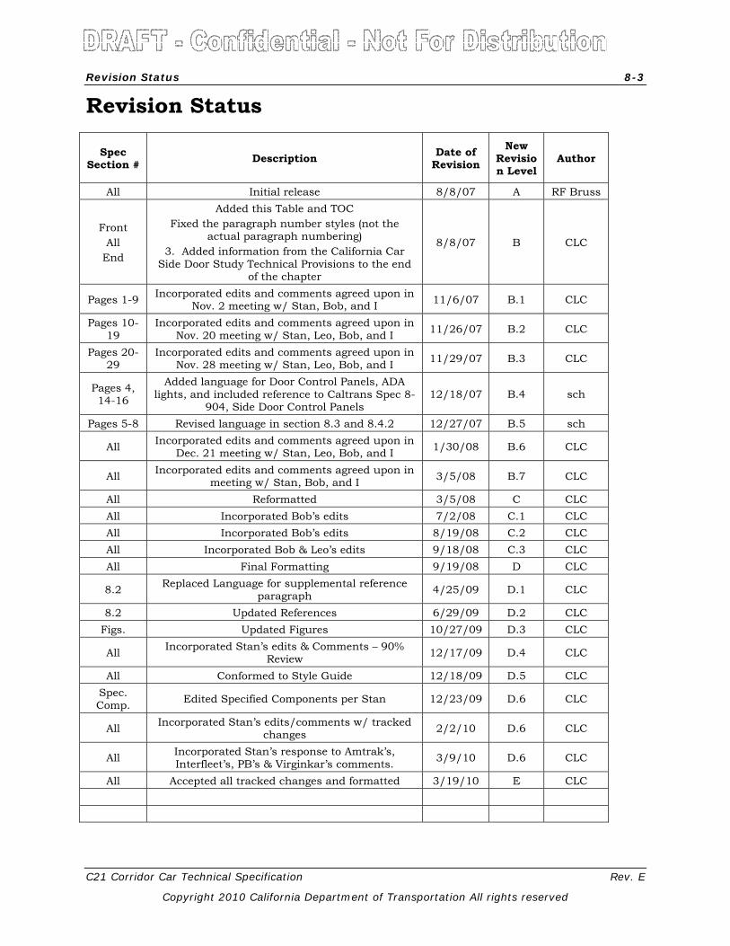
Revision Status
Spec Section # Description Date of
Revision New
Revision Level
Author
All Initial release 8/8/07 A RF Bruss
Front All
End
Added this Table and TOC Fixed the paragraph number styles (not the
actual paragraph numbering) 3. Added information from the California Car
Side Door Study Technical Provisions to the end of the chapter
8/8/07 B CLC
Pages 1-9 Incorporated edits and comments agreed upon in Nov. 2 meeting w/ Stan, Bob, and I 11/6/07 B.1 CLC
Pages 10-19
Incorporated edits and comments agreed upon in Nov. 20 meeting w/ Stan, Leo, Bob, and I 11/26/07 B.2 CLC
Pages 20-29
Incorporated edits and comments agreed upon in Nov. 28 meeting w/ Stan, Leo, Bob, and I 11/29/07 B.3 CLC
Pages 4, 14-16
Added language for Door Control Panels, ADA lights, and included reference to Caltrans Spec 8-
904, Side Door Control Panels 12/18/07 B.4 sch
Pages 5-8 Revised language in section 8.3 and 8.4.2 12/27/07 B.5 sch
All Incorporated edits and comments agreed upon in Dec. 21 meeting w/ Stan, Leo, Bob, and I 1/30/08 B.6 CLC
All Incorporated edits and comments agreed upon in meeting w/ Stan, Bob, and I 3/5/08 B.7 CLC
All Reformatted 3/5/08 C CLC All Incorporated Bob’s edits 7/2/08 C.1 CLC All Incorporated Bob’s edits 8/19/08 C.2 CLC All Incorporated Bob & Leo’s edits 9/18/08 C.3 CLC All Final Formatting 9/19/08 D CLC
8.2 Replaced Language for supplemental reference paragraph 4/25/09 D.1 CLC
8.2 Updated References 6/29/09 D.2 CLC Figs. Updated Figures 10/27/09 D.3 CLC
All Incorporated Stan’s edits & Comments – 90% Review 12/17/09 D.4 CLC
All Conformed to Style Guide 12/18/09 D.5 CLC Spec. Comp. Edited Specified Components per Stan 12/23/09 D.6 CLC
All Incorporated Stan’s edits/comments w/ tracked changes 2/2/10 D.6 CLC
All Incorporated Stan’s response to Amtrak’s, Interfleet’s, PB’s & Virginkar’s comments. 3/9/10 D.6 CLC
All Accepted all tracked changes and formatted 3/19/10 E CLC
Door Systems 8-4
C21 Corridor Car Technical Specification Rev. E
Copyright 2010 California Department of Transportation All rights reserved
8.0 Door Systems
8.1 Overview
Each car shall be equipped with four sets of electrically controlled, power operated side entrance doors located on the lower level that can be operated either from a local door control panel or via trainline OPEN or CLOSE commands from another location of the train. The side doors in the A-end vestibule of the café/lounge car shall be controlled only from a local door control panel. The F-end side doors on the cab/baggage cars will be controlled from a local door control panel, or from a trainline command, as selected by the crew by use of a trainline/local or local only selector switch. The side door system shall have a safety interlock that prevents the locomotive from developing traction effort if any side door is not fully closed and latched, or mechanically locked and isolated.
Each car shall also be equipped with two body end pocket doors located on the upper level (except cab/baggage cars which shall have a manually operated hinged door on the upper level at the F-end).
8.2 General Requirements
8.2.1 Design Objectives
Door systems have a demonstrated history of complexity and inconsistent performance that can affect the operation of passenger service and hinder maintenance and repairs. In order to maximize safety, system functionality and equipment availability, while minimizing the potential for degraded service or system performance, the side and end door systems shall be specified, designed and manufactured with an emphasis on addressing the following areas of concern:
• Unsafe conditions for passengers or crewmembers; • Train delays from malfunctioning side door equipment; • Poor system reliability in adverse operational and environmental conditions; • Accumulation of dust and dirt that affects system performance and cause failures; • System complexity that increases the time and effort required for troubleshooting and
repairs; and • Requirement for frequent adjustment and component replacement.
The door system shall be designed with great attention to details so that it is safe, very reliable, requires little maintenance, is easy to service, has support parts available and will have a long service life.
8.2.2 Design Requirements
The door system shall meet the requirements of Caltrans Specification 8-108 and APTA Standard SS-C&S-012-02, unless specified otherwise. The side door system shall be designed and constructed so that no single point malfunction of door system components shall create an unsafe condition. Door system failures shall be detectable through the following means:
• Failure to complete the door closed summary circuit and therefore prevent the locomotive from developing traction power (when a door panel is not fully closed and latched, or mechanically locked in the closed position and isolated electronically);
• Use of indicator lights that signal when a door is not confirmed closed and latched; and
Door Systems 8-5
C21 Corridor Car Technical Specification Rev. E
Copyright 2010 California Department of Transportation All rights reserved
• An indicator that signals when a door has been locked manually and isolated electrically.
All controls, locks and latches identified in this section shall use the standard Amtrak coach key (coach key), per Amtrak Drawing B-144 (J.L. Howard Part No. 2555).
When closed, the doors shall provide a weatherproof seal under all car operating conditions. Neither drafts, nor air noises shall be detectable from the closed door over the full range of operating speeds of the vehicle, on all specified classes of track. The doors shall operate as specified over the entire range of all operational, climatic and track climatic conditions identified in Caltrans Specification 1-106. None of the electrical components, such as limit switches, shall be directly exposed to the weather, even with the door open. Climatic and environmental conditions, such as dust, snow or heat, shall not be a cause of door system failures.
Door control relays and associated panels shall meet Amtrak Specification 528.
The door equipment mounting and internal fasteners shall be such that once adjustments are made and locked, they will not need to be disturbed until equipment overhaul or replacement. Fasteners shall be standard U.S. hardware. Jam nuts, lock washers, nylock nuts or equivalent fasteners shall be used to secure door equipment. Deformed nuts and fastening aids, such as Loctite or equivalent products, shall not be permitted, unless specifically approved by the Customer.
All door mechanisms, including but not limited to tracks, operators, wiring to door panels, stops, limit switches and controls shall be accessible by opening hinged access panels on the inside of the car. No special tools will be required to open such panels, nor will any equipment have to be disconnected or removed to gain access. Access shall be provided from inside the car to all points necessary for inspection, service, installation or removal. All door system equipment shall be installed in such a manner so as to be readily accessible to maintenance personnel with minimal effort. Adjustments shall be readily available from the exposed side of the door operator.
All door equipment of like function and the same hand shall be interchangeable without requiring modification. To this end, all component mounting holes for all door hardware shall be jig-drilled by the manufacturer. Likewise, mounting holes on the car shall also be jig-drilled. Door operators, door tracks and thresholds shall have their mounting positions controlled through suitable jigs/fixtures so as to ensure the correct physical relationship between carbody, door track, door pocket and operator.
All door operators, tracks, hangers, linkages, brackets, obstruction sensing and electrical fittings shall be manufactured or supplied by one subcontractor.
8.3 Powered Side Entrance Doors
Trainline-controlled, power operated bi-parting stainless steel side entrance plug or pocket doors (with fixed windows) shall be installed at the quarter points on each side of the car. Door control panels shall be installed on both sides of the B-end entrance of all cars, and in addition, a door control panel-local shall be installed in the A/F-end entrance of the café/lounge and cab/baggage car types. Refer to Figure 8-1.
Cars will be equipped with a wheelchair lift that will have an interlock with the side door system; refer to Chapter 4 for details.
The clear door opening shall be a minimum of 52 in. in width and a minimum of 76 in. in height.

Door Systems 8-6
C21 Corridor Car Technical Specification Rev. E
Copyright 2010 California Department of Transportation All rights reserved
Major door system components: door panels, door operator and door control panels shall include vendor identification, which includes (but is not limited to) the following information:
• Vendor name • Vendor part number • Serial number • Customer part number (if applicable) • Date of manufacture • Revision level
8.3.1 Side Door Controls and Operation
The side door controls shall include the following features:
• Trainline control at 74 Volts Direct Current (VDC) via 27 point communication trainline cable, in compliance with Amtrak Drawing A-63-7676-1.
• Relay-based logic and discrete trainlines for the issuing of control commands to the doors. Discrete trainlines shall also be used to monitor the door closed and locked status of all doors in the train, and for providing the required indications to the train crew.
• The door control system shall incorporate fail-safe logic so that no unsafe condition will be created through normal operation of the door system, or due to a failure of door system equipment or components.
• Door control panels shall be located adjacent to side doors 3 and 5 in the B-end lower level vestibule of all cars.
• A door control panel-local shall be located adjacent to door 7 in the A/F-end lower level vestibule on cab/baggage and café/lounge cars.
• Each door leaf shall be provided with a position sensor to detect that the door is fully closed and that it is mechanically latched.
• Redundant zero-speed protection from wheel slide control unit on each car including all of the following: • Door control panel system deactivation if not at zero-speed. • Removal of power from door open function of door operator if not at zero speed. • Door CLOSE command automatically issued in both directions on left and right door
close trainlines when car motion is detected. • Zero-speed signal supplied by the wheelslide control unit shall be required in order to
issue an OPEN command to the side doors. Conversely, the absence of a zero speed signal shall prohibit the issuance of an OPEN command to the side doors.
• Sensitive edge on each door leaf meeting ADA requirements. • Weatherproof crew key switch outside doors 3 and 6, adjacent to the B-end vestibule of
all cars, as well as outside doors 2 and 7, adjacent to the A/F-end of the café/lounge and cab/baggage cars, which allows crew to open or close a single door (both panels) to enter or exit the car.
• Manual emergency release for each door leaf from inside the car, with frangible cover. • Exterior emergency release for each door leaf, fully enclosed behind a weatherproof
cover. • Mechanical lock which can be engaged manually with a coach key from inside the car
which allows the on-board crew to secure the door leaf closed and isolate the door operator electrically.

Door Systems 8-7
C21 Corridor Car Technical Specification Rev. E
Copyright 2010 California Department of Transportation All rights reserved
• Door control system which can tolerate two separate grounds anywhere in the train in the door circuits and not have an unintended door opening.
• Control system design shall be fault tolerant to prevent unintended door openings. • Yellow Light Emitting Diode (LED) door status indicator above each door panel, which
shall be illuminated when that door panel is open, extinguished when that panel is closed and latched and flashing when the panel is mechanically locked.
• A red exterior LED-type door open indication shall be provided (see Chapter 11). • A blue ADA exterior LED indicator, located on each side of the car adjacent to each door
opening (excluding the service entrance doors at the A-end of the café/lounge and the F-end baggage area access doors on the cab/baggage cars) that flashes at 1 Hertz (Hz) while the doors at that opening are open, and that flash at 2 Hz when a CLOSE command has been given to that door opening (see Chapter 11).
• Audible signal, on or near the door header at each side door opening that pulses at the same rate as the blue ADA indicator light. Tone and volume of audible signal to be submitted to the Customer for approval during design review. DR
• Traction interlock with the door closed indication so that traction cannot be applied unless the doors are closed and latched, or mechanically closed and locked and electrically isolated. (There is no interlock between the door closed summary circuit and the brake system.)
• Interlock with the car-borne wheelchair lifts at doors 3/4 and 5/6 that prevent the doors from closing when the wheelchair lift is deployed at that door opening.
8.3.2 Side Door Operator and Linkage
The side doors shall employ electric or electro-pneumatic operators, one per door leaf. Doors shall be operated from the nominal 74VDC car battery system, but shall operate normally over the full voltage range from normal Head End Power (HEP) to load drop (from 45-86VDC) without damage and without affecting the reliability and serviceable life of the operator. The Contractor shall provide an engineering analysis to verify door operators will reliably operate over this voltage range without damage to components.
The operator shall include an over-center or equivalent locking mechanism so that a door which is closed will remain closed and latched upon loss of electrical or pneumatic power, regardless of car vibration.
The operator and linkage for each panel shall be arranged so the maximum force required to manually move a door panel shall not exceed 30 pounds of force (lbf) at mid-point of travel.
The drive mechanism shall be designed to minimize torque applied to door panels during operation. The door operator shall decelerate the door leaves at each extremity, to preclude slamming or rebound, and bring them to rest gently at the extremity of door leaf travel. The door motion shall be smooth and free of shock and impact. Damping shall be provided at the ends of travel of the door panel in both the opening and closing directions.
Operator design shall be such that a mechanical or electrical failure shall not result in subsequent damage to other equipment.
All limit switches and proximity sensors used in the operator shall be hermetically sealed and shall be easily replaceable. All limit switches and proximity sensors shall be precision units that are positively and precisely located so they may be replaced without the need for mechanism adjustment.
Door leaf travel shall be easily adjustable, with provisions, to set open and close positions.
Door opening and closing times shall be independently adjustable and shall be initially set with Direct Current (DC) bus voltage with HEP on, at:

Door Systems 8-8
C21 Corridor Car Technical Specification Rev. E
Copyright 2010 California Department of Transportation All rights reserved
Opening 2 (± 0.5) seconds
Closing 2 (± 0.5) seconds
With reduced voltage the door opening/closing times shall be a maximum of 6 seconds. Contractor to supply the method of adjusting times and a demonstration of compliance along with an analysis of operation in reduced power scenario, down to the specified minimum voltage.
The doors shall open or close successfully with no greater than a 60 lbf applied perpendicular to the interior door surface at a height of 56 in. above the floor, throughout the entire opening and closing cycle.
Stall protection will be provided to prevent operator or control damage or degradation should a leaf be immobilized. When the problem is corrected, the operator will not require a manual reset to return to operation.
If the door operator uses a lead screw drive system, the screw shall not require any lubrication. The door motion shall be smooth and free of shock and impact. Damping shall be provided at the ends of travel of the door panel in both the opening and closing directions.
The operator shall be capable of holding the door, without oscillation, in either an open or closed position with the car on all configurations of track as specified in Caltrans Specification 1-106.
The door operators shall include a local cutout switch which allows the on-board crew to deactivate and isolate a door operator by locking the door with a mechanical mortise lock.
The door operator shall be designed so that it requires adjustments no more frequently than once per year. The door motor and operator assembly shall be suitable for operation without component replacement between heavy overhaul periods of at least eight years. All door operator motors shall be interchangeable from one door position to another. The door motor shall be suitably protected from the surrounding environment and be of a sealed design.
8.3.3 Door Panel Construction
Side entrance doors shall be constructed of stainless steel and have a honeycomb core. Doors shall be of an adequate thickness for the intended service, which means they shall be resistant to damage from impacts with roadside debris such as rocks, as well as resist being bent from misuse, attempted operation with the door stuck, or a mechanical malfunction. In addition, the door leaf shall sustain when supported at both ends, a concentrated load of 250 lbs applied over 4 in.2, 90° to the plane of the panel at the center of the front face without deflecting more than 0.25 in., nor shall the panel take a permanent set.
All door panel joints and edges shall be sealed against moisture. Stainless steel reinforcements shall be provided at attachment points. Structure used to secure the door leaf to the door hanger shall last the life of the car, without fatigue cracks or similar failure, even if the door operator malfunctions and slams the door leaf repeatedly. Epoxy used in door panel construction shall be waterproof.
All internal door leaf wiring and sensitive edge tubing shall be run through internally routed conduit.
The exterior surface of the door panel shall match that of the exterior of the car body.
The sensitive edge and door mounted weather seals shall be part of the door panel assembly.
Door panels shall be insulated against thermal and sound transmission.
Door panels shall be welded in accordance with all applicable AWS requirements.
Door Systems 8-9
C21 Corridor Car Technical Specification Rev. E
Copyright 2010 California Department of Transportation All rights reserved
8.3.4 Door Windows
Each door panel shall have window openings formed to accept FRA Part 223 compliant glazing. The door window frame shall be an integral part of the door structure and shall be capable of retaining the window in the door opening when subjected to the impact applicable to the window location described in 49CFR Part 223. The window and its glazing shall not extend beyond the outer surface of the door.
Side door windows shall be tinted to match side window specification.
All door windows shall be retained in the door frame by use of a rubber extrusion and zip strip combination which will allow installation/removal of the glazing from inside of the door.
8.3.5 Sensitive Edge
The leading edge of side door leaves shall be equipped with a mechanical sensitive edge. Should the door close against an obstruction, activation of the sensor shall immediately initiate the door opening cycle. The force required to activate the sensor shall not exceed 20 lbf. The sensitivity of the obstruction detection system shall conform to APTA Standard SS-C&S-012-02.
Design of the sensitive edge and controls shall not allow the door to oscillate if no obstruction is present. The sensitive edge shall form an interlocking weatherproof seal with the sensitive edge on the adjacent door panel.
8.3.6 Overhead Door Track
Door leaves shall be suspended from an overhead door track. The track and door hanger assembly shall have minimum service life of 25 years. The load bearing surface of the door track shall be convex, so as to be self-cleaning from buildup of dust. The door track shall employ rollers with sealed, permanently lubricated bearings or other roller design that does not require lubrication. The overhead door track and rollers shall not be affected by environmental conditions, including the accumulation of dust. The door hanger and door track shall be able to resist, without damage or permanent deformation, a force of 200 lbf applied perpendicularly at the center of the door panel, both in inward and outward directions.
The rollers shall be secured to the hanger assembly with a mechanism, both to adjust for level as well as control vertical free-play between the hanger assembly and door track. Door leaf adjustment shall allow the space between the nosing seal to be made constant from the top to the bottom of the leaf. The amount of track-to-roller free-play shall prevent the trailing edge roller from lifting on the track if the door leaf strikes an obstruction down low while closing. Adjustment of free-play clearances shall be easily done using standard tools.
The track itself and mounting to carbody (not the door-to-hanger connection) shall be adjustable to accommodate both carbody and door leaf tolerances, including both height and plumb.
The door track/hanger shall not require lubrication over its life.
8.3.7 Bottom Door Guides and Thresholds
A door guide with corresponding threshold shall be provided at the bottom of the door. Adjustable wear strips, if provided, shall be easily replaceable without removing or readjusting the door panel. The bottom guide arrangement shall be designed not to collect dirt and debris and to ensure a low friction operation with no binding or rattling. The thresholds shall be compliant with ADA requirements. The door guide/threshold shall form part of the door weather seal and shall incorporate drain holes to carry off water to the underside of the car. The threshold and drain and their sealing to the carbody shall ensure that water or other fluids

Door Systems 8-10
C21 Corridor Car Technical Specification Rev. E
Copyright 2010 California Department of Transportation All rights reserved
do not seep underneath and cause deterioration of flooring, its substructure or insulation. Easy access shall be provided to the door guide/threshold for cleaning and maintenance. The guide shall be adjustable to accommodate both carbody and door leaf tolerances. Any part of the door guide system subject to wear shall be easily replaceable without removing the door panels. The bottom guide shall require adjustments no more frequently than every 460 days.
The threshold shall incorporate a freeze protection heater in accordance with Chapter 10.
8.3.8 Weather Seal
The leading edge of the door panel shall interlock with the adjacent door panel to form a weatherproof seal. The door opening, including the interior and exterior sides and top, shall be equipped with a flexible weather seal. The rear edge of the leaf shall be equipped with a batten that positively engages the door seal when the door is fully closed, including the radius at the top of the door opening. This combination shall create a dust and weatherproof seal. The seal shall be attached to the door frame with sufficient clearance so as to prevent chafing against the leaf as it moves, yet ensure every door leaf seals on every car, despite the combination of all manufacturing tolerances. The top of the opening shall also be equipped with a weather seal. The interface between the bottom of the door and the threshold shall form a weather seal. Seal design shall also limit the entrance of dust and snow into the door pocket when the door is open. Adjustments to keep the seal system weather tight shall not be required more often than annually. The weather stripping shall be easily replaceable and maintain a hardness index of 60 to 70 durometer (if rubber) at -30°F. The entire door seal arrangement shall be demonstrated to provide an effective door seal under all operating conditions. DR
8.3.9 Door Leaf Wiring
Wiring and air tubing within the door leaf shall be configured to allow individual door elements (sensitive edge, mechanical lock, etc) to be easily replaced.
Wiring or air tubing connecting the door leaf to the carbody shall be designed to avoid snagging, abrasion or other damage regardless of car/door motion. The door leaf wiring shall be a sealed design and suitably protected from the surrounding environment. The door panel shall be grounded per APTA Standard SS-E-005-98. Cable and/or air tubing carried with the operator linkage to the door leaf shall be secured, so that any motion imparted to the cable by car motion will not result in cable snagging, abrasion or other damage. Access shall be provided to easily replace and terminate the cable.
8.3.10 Emergency Releases
Manual interior and exterior emergency releases shall be provided to allow each side door panel to be opened manually in emergency situations. The emergency release handle shall be red and be simple for individuals to understand and operate. Activating the emergency release handle shall: remove power from the door motor, release the door mechanical lock (if locked) and disengage the door over-center locking mechanism and separate the door panels by at least one inch so that the door leaf may be manually opened. Using the emergency release, the force to disengage the door operator and to move the door leaf shall not exceed 30 lbf external per APTA Standard SS-C&S-012-02.
The exterior emergency release handle shall be located on the car side, near the door it releases, behind a weatherproof cover. At least one release shall be provided for each door opening that permits the opening of both door leaves. The cover shall allow access in an emergency and be able to be sealed and locked for securing car when not occupied. Operating instructions shall be provided on or near the cover.
An interior emergency release handle shall be located adjacent to each door leaf, behind an easily replaceable, transparent frangible weatherproof cover. To allow crew access to the

Door Systems 8-11
C21 Corridor Car Technical Specification Rev. E
Copyright 2010 California Department of Transportation All rights reserved
release emergency release without breaking the frangible material, such as when the car has no power, the cover frame shall be hinged and equipped with a coach key release. Opening the frame will also allow the frangible material to be easily replaced. The inside handle, once actuated, shall remain in the actuated position. Operating instructions for the emergency door release mechanism shall be installed near the emergency release, per the location and illumination requirements of 49CFR Part 238.
It shall be possible for emergency personnel to manually open the side doors from outside the car with the car resting on its side, by using only tools normally carried by such personnel. This shall be demonstrated with an exterior door and frame assembly in the horizontal position, using actual production components. It shall be assumed that no damage exists to the door, door frame or operating mechanism.
If a cable system is employed between the external release handle and door operator, it shall be run within a conduit to allow it to be replaced easily, without major car disassembly.
Appropriate labels shall be provided with operating instructions at convenient locations, consistent with APTA Standard SS-PS-002-98.
8.3.11 Door Control Panel
A door control panel shall be provided on both sides of each car to provide train crew control of all side doors on its respective side of the train. The panel shall be located in accordance with Figure 8-1. The panel shall be activated with a coach key, with the key removable only in the OFF position. Indicator lights on the panel shall employ socket-mounted LED technology.
The design, function and operation of the door control panels shall be in accordance with Caltrans Specification 8-104.
8.3.12 Door Control Panel-Local
The cab/baggage and café/lounge car types shall be equipped with a door control panel-local in the A/F-end lower level service vestibule to allow control of the A/F-end side doors.
The design, function and operation of the door control panel-local shall be in accordance with Caltrans Specification 8-104.
The side doors in the lower-level service vestibule of the café/lounge and cab/baggage cars shall be subject to the same redundant zero speed protection logic as identified above, and shall be incorporated into the trainline door close summary circuit.
In addition, the cab/baggage car shall be equipped with a trainline/local coach key switch panel which allows the crew to select whether the baggage area doors open in response to trainline OPEN commands, or only on a local basis (as may be used when baggage is checked). Positions shall be labeled TRAINLINE/LOCAL (9 o'clock position) and LOCAL ONLY (6 o'clock position). The coach key is removable from either position. With the switch in the LOCAL ONLY position, the connection from the door open trainline is interrupted, so that the baggage area doors only open upon an OPEN command from the door control panel-local or the crew access switch adjacent to those doors, and shall not open in response to a trainline OPEN command from another door control panel. When in the TRAINLINE/LOCAL position, the side doors at this location shall open either upon a trainline OPEN command from another door control panel, or from the adjacent door control panel-local or exterior crew access switch. In either position, the doors will close upon a CLOSE command from the door control panel-local, or from a trainline CLOSE command.
Both panel types shall be weatherproof so no damage will occur nor the system be disabled by a door being left open and the station getting wet, such as in going through a carwash. The switches themselves shall be weatherproof.
Door Systems 8-12
C21 Corridor Car Technical Specification Rev. E
Copyright 2010 California Department of Transportation All rights reserved
8.3.13 Conductor's Single-Leaf Momentary Control Switch
The door leaf adjacent to each door control panel shall be equipped with a momentary crew switch located in the hand hold adjacent to that door leaf, to permit that door leaf to be opened by the crew as the train is arriving or departing at a station. This conductor's single-leaf momentary control switch shall operate when all the following conditions are met:
• It shall be activated only when the adjacent door control panel is keyed on; • It shall be activated only when car speed is below 20 mph, as measured by the wheel
slide control unit; and • It shall fully open the adjacent door leaf when the momentary switch is closed and held
closed by the crewmember. Releasing the momentary switch shall close the door leaf.
When the above conditions are met, pressing the momentary conductor’s door switch, located in the interior grab handle adjacent to the door control panel, will result in the adjacent door leaf opening. Should any condition no longer exist, the door leaf will close. The switch itself shall be weatherproof. Opening the door leaf with the momentary control switch shall not break the door closed summary circuit as long as the adjacent door control panel is keyed on.
8.3.14 Exterior Crew Key Switches
A weather proof coach key switch, Vapor p/n 58540688-10, complete with seal over key opening and detent latch, shall be provided adjacent to doors 3and 6 on each side of all cars which allows crew to open or close the adjacent door leaves to enter or exit the car. The cab/baggage and café/lounge car types shall also be equipped with an additional crew key switch on each side of the car on the A/F-end of the car, adjacent to doors 2 and 7, which allows crew to open or close the adjacent door to enter or exit the car. See Figure 8-1.
The switch shall be three-position, spring return to center, with key capture in open and closed positions. Rotating the key to the left shall open the doors, and to the right shall close the doors.
The crew key switch shall be arranged so that when the key is removed, the door shall remain in the last position commanded. Trainline commands shall take precedence over local commands. If a door is opened with the local crew key switch, it shall be possible to close it by trainline control. Switches within the assembly shall be weatherproof.
8.3.15 Door Cutout and Mechanical Lock
A positive mechanical lock function shall be provided for each passenger side door leaf, to deactivate power from that door operator and to secure the leaf in the fully closed position. This lock shall be operated from inside the car only, by a coach key, and shall engage the door leaf directly. When closed and locked in this manner, the door latched sensing switch shall be bypassed. The door latched sensor shall only be bypassed when the door leaf is fully closed and the mechanical lock fully engaged.
The emergency release function shall still be available for a locked out door, but if the release is used, the door panel locked sensing function shall be reactivated. If the emergency release has been activated while the mechanical lock was in the locked out position, the design of the keeper shall allow the lock bolt to re-engage automatically when the door leaf is again closed (so as to not ram the edge of the keeper with the bolt).
Engagement of the lock bolt shall be 0.375 in. minimum. It shall not be possible to withdraw the key unless the lock bolt is fully engaged or fully unlocked.

Door Systems 8-13
C21 Corridor Car Technical Specification Rev. E
Copyright 2010 California Department of Transportation All rights reserved
8.3.16 Door Status Indicators and Alarms
Audible and visual warnings that comply with the requirements of 49CFR Parts 37 and 38 shall be provided at each doorway and shall be activated prior to door closing. Activation of the warnings shall precede the initiation of door closing by approximately 3 seconds. The warnings shall alert passengers inside and outside the car on the side of the car at which the doors are open.
8.3.16.1 Exterior Door Open Indicators
A red exterior LED type door open indication shall be provided on each side of the car at each entrance doorway (4 per car) (see Chapter 11). Both lights adjacent to an individual vestibule shall be extinguished when all doors at that entrance vestibule (both sides of car) are closed and locked. The indicator shall be Dialight p/n 556-0001-805 or 556-0003-802.
8.3.16.2 Exterior ADA Indicators
A blue ADA LED indicator shall be provided outside each side entrance door as follows (see Chapter 11):
• Coach car: all door openings (4 per car) • Cab/baggage and café/lounge cars: B-end door openings only (2 per car)
The ADA indicators shall be triggered via the door controls to provide a flashing indication at 1 Hz while the doors at that location are open, and shall flash at 2 Hz from the time that a CLOSE command is issued to those doors until the doors are closed and locked (see Chapter 11).
8.3.16.3 Interior ADA Door Closing Indicators and Alarms
Red, LED interior door closing warning lights shall be provided in the door header at each side entrance door.
These lights shall be triggered via the door controls to provide a flashing indication, upon initiation of the door “close” command, and continue to flash until the door begins to close. This is to warn hearing impaired passengers that the doors are about to close. The flashing rate of the indicator shall be approximately 2.0 Hz. The indicators shall be Vapor p/n 59621431, including the connector.
Interior door closing warning audio alarm shall be provided in the door header at each side entrance door as follows:
• Coach: all door openings (4 per car) • Cab/baggage and café/lounge: B-end door openings only (2 per car)
These audio alarms shall be triggered via the door controls to provide a pulsing audio, upon initiation of the door CLOSE command, and continue to sound until the door begins to close, to warn passengers that the doors are about to close. Sound level shall be 88 +/-2 decibels (dB) at 5 ft 6 in. above the center of the door threshold, with a frequency of 3000 Hz. The audio alarms shall be Vapor p/n 57511603-03.
An interior door closing interlock with Public Address (PA) system to initiate “doors closing” message shall be provided. See Chapter 12.
When the door closed trainline is activated, a 3 second warning of the above visual and audio devices will be given at each entrance area before the doors begin to close.
Door Systems 8-14
C21 Corridor Car Technical Specification Rev. E
Copyright 2010 California Department of Transportation All rights reserved
8.3.16.4 Interior Door Status Indicators
Each door leaf shall be equipped with a yellow LED indicator light mounted in the ceiling panel over each door leaf. This indicator shall display the status of the door leaf:
• On continuously: Door leaf is open, or is not confirmed closed and latched. • Flashing (1 Hz): Door leaf is locked manually with the mortise lock and isolated from
the door control circuit and the door closed summary circuit. • Off: Door panel is confirmed closed and latched, but not locked with the mortise lock.
8.3.17 Design Safety Validation
The Contractor shall conduct a hazard analysis and a Failure Mode and Effects Criticality Analysis (FMECA) for hardware and a Fault Tree Analysis (FTA) for the entire side door system as necessary to demonstrate that the safety requirements of the system are met under all operating conditions. This shall include: logic, interlocks, mechanical mechanisms, indicators, bypasses, cutouts and controls. The analysis shall be presented to the Customer for approval during design review.
8.3.18 Tests
The doors and their operating equipment shall be tested and adjusted on all cars to assure smooth functioning, attainment of the required speed of operation, and proper functioning of all associated controls, signals and interlocks.
The obstruction detection features shall be checked for proper operation and adjusted, if necessary prior to the start of the cycling test. This feature shall operate properly, without the need for adjustment, at the end of the cycling tests.
See Chapter 19 for the door system testing requirements.
8.3.19 Door Pocket
If pocket doors are provided, the door pocket will accommodate the door leaf while the door is open. Since the bottom of the door pocket is a wet area, it shall be lined with corrosion resistant material to prevent deterioration of car structure and flooring. This pan shall be designed to drain water out of the pocket area through a tube to the underside of the car. It shall be designed to ensure that water does not seep underneath and cause deterioration of flooring, its substructure or insulation. The drain shall be easily accessible for cleaning, and shall be equipped with a backflow preventer to keep dust and moisture from blowing into the pocket.
8.3.20 Door Markings
Door positions (# 1 - 8) shall be numbered in accordance with Caltrans Drawing A-8-902. In addition, they shall be labeled for emergency egress in accordance with APTA Standard SS-PS-002-98, Rev. 2.
Signage shall be installed on each door leaf that describes the procedure for opening the doors in the event of an emergency. This signage shall conform to the requirements of APTA Standard SS-PS-002-98 and 49CFR Part 238.
Signage shall also be provided above each door leaf or pair of door leaves, adjacent to the yellow door status LED indicator, that states that the door leaf is inoperative or out of service when the yellow light is flashing.
A sign shall be installed on the exterior of the A-end vestibule doors on the café/lounge car that states NO PASSENGER ENTRANCE.

Door Systems 8-15
C21 Corridor Car Technical Specification Rev. E
Copyright 2010 California Department of Transportation All rights reserved
The proposed artwork, material, color, size, location and adhesive for these signs shall be submitted for Customer approval during the design review.
8.4 Powered Body End Frame Doors
Electrically operated, stainless steel, single leaf body end frame doors, with fixed windows, shall be provided at each end of the car except the cab end of the cab/baggage car. A minimum 32 in. "clear passage" shall be provided through the doorway when the door is fully opened.
Refer to Figure 8-2.
Major door system components: door panel, door hanger assembly and door operator shall include a stainless steel vendor nameplate, which includes the following information:
• Vendor name • Vendor part number • Serial number • Date of manufacture • Revision level
8.4.1 Body End Door Controls and Operation
Body end door controls shall include the following features:
• Push and kick plates labeled PRESS (hand and foot height) on both sides of the door for activation. Plates on the exterior side of door to be weatherproof.
• Timed opening sequence in which the door responds to the push plate and remains open for 15 seconds (over a range ± 5 seconds) before closing.
• Detent which will hold the door closed upon loss of power. • Hold-open feature, so that door will not oscillate during the open interval when the car
leans toward the door closing direction. • Mechanical sensitive edge (air bladder type). • 3-position switch inside and outside the door with red switch guard. • Removable emergency egress panel in the door leaf, in accordance with 49CFR Section
238.235 (e).
8.4.2 Door Operator and Linkage
The door operator and controls shall operate from nominal 7VDC car battery system, but operate normally over the entire voltage range of charging down to load shed without damage and without affecting the reliability and serviceable life of the operator.
The drive mechanism shall be designed to minimize torque applied to the door panel during operation. The door operator shall preclude slamming or rebound, and bring it to rest gently at the extremity of door leaf travel. The door motion shall be smooth and free of shock and impact. Damping shall be provided at the ends of travel of the door panel in both the opening and closing directions. In the opening direction damping shall preclude the door leaf from contacting the mechanical door stop.
Operator design shall be such that a mechanical or electrical failure shall not result in subsequent damage to other equipment. For example, if the operator linkage to the leaf comes loose, it shall not be possible for the operator to damage itself from over-travel of the mechanism. The door operator and drive motor shall be protected from damage created by in-service conditions.

Door Systems 8-16
C21 Corridor Car Technical Specification Rev. E
Copyright 2010 California Department of Transportation All rights reserved
All limit switches and proximity sensors used in the operator shall be hermetically sealed and easily replaceable. All limit switches and proximity sensors shall be precision units that are positively and precisely located so they may be replaced without the need for mechanism adjustment.
Door leaf travel shall be easily adjustable through a single adjustment point to set open and close positions.
Door opening and closing times shall be independently adjustable and shall be initially set with DC bus voltage with HEP on, at:
Opening 2.5 (± 0.5) seconds
Closing 3.0 (± 0.5) seconds
The door shall open or close successfully with no more than a 60 lbf applied perpendicular to the interior door surface at a height of 56 in., throughout the entire opening and closing cycle.
Stall protection will be provided to prevent operator or control damage or degradation should a leaf be immobilized. When the problem is corrected, the operator will return to full functionality without a manual reset. Thermal cutouts shall not be used for motor protection. The door motion shall be smooth and free of shock and impact. Damping shall be provided at the ends of travel of the door panel in both the opening and closing directions.
The operator shall be capable of holding the door, without oscillation, in either an open or closed position with the car in service. Also, the operator shall include an over-center mechanism so that a door will remain in the open or closed position upon loss of power. The operator and linkage for the doors shall be arranged so the maximum force required to manually move a door panel with power removed shall not exceed 20 lbs.
Door motor control and timing function shall be incorporated on the operator unit.
The door operator shall require adjustments no more frequently than every 460 days. The door motor and operator assembly shall be suitable for operation without component replacement between heavy overhaul periods of at least eight years. All door operator motors shall be interchangeable from one door position to another. The door motor shall be a sealed design and suitably protected from the surrounding environment.
8.4.3 Door Panel Construction
Body end doors shall be constructed of stainless steel and have a honeycomb core. In addition, the door leaf shall sustain, when supported at both ends, a concentrated load of 250 lbs applied over 4 in.2, 90° to the plane of the panel at the center of the front face without deflecting more than 0.25 in. nor shall the panel take a permanent set.
All door panel joints and edges shall be sealed against moisture. Stainless steel reinforcements shall be provided at attachment points. Structure used to secure the door leaf to the door hanger shall ensure it lasts the life of the car, without fatigue cracks or similar failure, even if the door operator malfunctions and slams the door leaf repeatedly.
The lower portion of the door shall be equipped with an emergency egress knock-out panel, in accordance with 49CFR Section 238.235 (e). The panel shall be clearly labeled and simple to use. The panel and the method of securing it shall not extend beyond the face of the door leaf on either side. The panel shall meet the required release forces, but be securely attached to the main body of the door leaf so as to not vibrate, squeak, whistle or leak water. The panel shall only be removable without tools from the inside. It shall be possible to easily non-destructively test the knock-out function and then reinstall the panel without damage or marring of either part.
A hand-hold recess shall be provided on both sides of the door panel to allow manual opening of the door from the inside and outside, with the operator deactivated.
Door Systems 8-17
C21 Corridor Car Technical Specification Rev. E
Copyright 2010 California Department of Transportation All rights reserved
Cutouts shall be provided on the inside and outside panels for the two push and kick plates and associated wiring. All internal door leaf wiring and sensitive edge tubing shall be run through internally routed conduit.
Each door panel shall have window openings formed to accept FRA Part 223 Type I compliant glazing. The door window frame shall be an integral part of the door structure and shall be capable of retaining the window in the door opening when subjected to the impact applicable to the window location described in 49CFR Part 223. The glazing and its mounting system shall not extend beyond the outer surface of the door.
Door panels shall be fully insulated against thermal and sound transmission and grounded per APTA Standard SS-E-005-98. Door panels shall not rattle or vibrate.
8.4.4 Push and Kick Plates
The right hand side of the door leaf (as viewed from inside of the passenger seating area of the car) shall be equipped with a pair of push and kick plates, operable from both sides of the panel, for door activation. Plates shall be embossed and labeled in white text PRESS, and shall be weatherproof both within themselves and also to the exterior face of the door panel. The push plates shall be recessed and be flush with the surface of the door. They shall not interfere with the operation of the door as it travels in and out of the pocket. The internal micro-switch shall be a weatherproof design.
The Contractor may propose alternative designs to control the opening of the end doors, to be reviewed and approved by the Customer as part of the door system design review. DR
8.4.5 Sensitive Edge
The leading edge of the door leaf shall be equipped with an air bladder-type mechanical sensitive edge. Should the door close against an obstruction, activation of the sensor shall immediately initiate the door opening cycle. The force required to activate the sensor shall not exceed 20 lbf. The sensitivity of the obstruction detection system shall conform to APTA Standard SS-C&S-012-02.
Design of the sensitive edge and controls shall not allow the door to oscillate if no obstruction is present. The sensitive edge shall form an interlocking weatherproof seal with the adjacent door frame seal.
8.4.6 Overhead Door Track
Door leaves shall be suspended from an overhead door track. The track and door hanger assembly shall have minimum service life of 25 years. The track shall be convex with the curve on top, so as to be self-cleaning from buildup of dust. The door track shall employ concave rollers, with sealed, permanently lubricated bearings. The overhead door track and rollers shall not be affected by environmental conditions, including the accumulation of dust. The door hanger and track shall be able to resist without damage or permanent deformation a force of 200-lbf applied perpendicular at the center of the door panel both in either the inward or outward directions.
The rollers shall be secured to the hanger assembly with a mechanism, both to adjust for level as well as control vertical free-play between the hanger assembly and door track. Door leaf adjustment shall allow the space between the nosing seal to be made constant from the top to the bottom of the leaf. The amount of track-to-roller free-play shall prevent the trailing edge roller from lifting on the track if the door leaf strikes an obstruction down low while closing. Adjustment of free-play clearances shall be easily done using standard tools.
The track itself and mounting to carbody (not the door-to-hanger connection) shall be adjustable to accommodate both carbody and door leaf tolerances, including both height and

Door Systems 8-18
C21 Corridor Car Technical Specification Rev. E
Copyright 2010 California Department of Transportation All rights reserved
plumb.
The door track and hanger shall not require lubrication over its life.
8.4.7 Bottom Door Guides and Thresholds
A door guide with corresponding threshold shall be provided at the bottom of the door. Wear strips, if provided, shall be easily replaceable without removing or readjusting the door panel. The bottom guide arrangement shall ensure operation with no binding or rattling. The door guide/threshold shall form part of the door weather seal and shall incorporate drain holes to carry off water to the underside the car. The threshold and drain and their sealing to the carbody shall ensure water or other fluids do not enter the equipment room, nor do they seep underneath and cause deterioration of flooring, its substructure or insulation. Easy access shall be provided to the door guide/threshold for cleaning and maintenance. The guide shall be adjustable to accommodate both carbody and door leaf tolerances. The bottom guide shall not require adjustments more often than every 460 days.
8.4.8 Weather Seal
The leading edge of the door panel shall interlock with the door frame to form a weatherproof seal. The interior and exterior of the door opening, including any curves at the top, shall be equipped with a flexible weather seal. The rear edge of the leaf shall be equipped with a batten that positively engages the door seal when the door is fully closed, including any radius at the top of the door opening. This combination shall affect a dust- and weatherproof seal. The seal shall be attached to the door frame with sufficient clearance so as to prevent chafing against the leaf as it moves, yet ensure every door leaf seals on every car, despite the combination of all manufacturing tolerances. The interface between the bottom of the door and the threshold shall form a weatherproof seal. When door is manually locked a seal shall prevent air infiltration. Seal design shall also limit the entrance of dust and snow into the door pocket when the door is open. The entire door seal arrangement shall be demonstrated during the design review process to provide an effective door seal under all operating conditions and is subject to Customer approval. DR
8.4.9 Door Leaf Wiring
Wiring and air tubing within the door leaf shall be configured to allow individual door elements (push plates, sensitive edge, mechanical lock, etc) to be easily replaced.
Wiring connecting the door leaf to the carbody shall be designed to avoid snagging, abrasion or other damage regardless of car/door motion. The door leaf wiring shall be a sealed design and suitably protected from the surrounding environment. The door panel shall be grounded per APTA Standard SS-E-005-98. Cable carried with the operator linkage to the door leaf shall be secured, so that any motion imparted to the cable by car motion will not result in cable snagging, abrasion or other damage. Access shall be provided to easily replace and terminate the cable.
8.4.10 Inside and Outside Door Control Switches
Each end door shall be equipped with a three-position door cutout switch on the inside and outside of the door opening. The switches shall be located on the right side of the door opening, when inside the car facing outward. The switches shall be clearly distinguished from the emergency fan switches, located nearby. The switch shall have three positions, with two positions maintained (MANUAL and NORMAL), and the third position shall be momentary contact (OPEN). The switch and plate shall be keyed so switch cannot be mounted backwards. A red switch guard shall be provided, which closes fully only when the switch is in NORMAL position. The switch plate will be labeled from the bottom upward, OPEN, NORMAL and MANUAL.

Door Systems 8-19
C21 Corridor Car Technical Specification Rev. E
Copyright 2010 California Department of Transportation All rights reserved
This switch allows a door to be deactivated when in MANUAL mode. It also allows a five minute open duration when placed in the momentary OPEN position, after which the door operation goes back to normal. Timeout can be cancelled by moving the switch briefly to MANUAL, than back to NORMAL. The switch can also be used to allow the door to be opened manually in an emergency.
See Figure 8-2 for switch location.
8.4.11 Positive Mechanical Door Lock
A positive mechanical door lock, operable with a coach key from either side of the door, shall be provided to positively secure the door panels in the closed position at the ends of the train. The lock shall incorporate a weatherproof switch which deactivates the push plates and door operator when the door is locked. The key opening shall be equipped with a self-closing dust flap; the lock itself shall be sealed against dust.
The door system shall be designed so that no damage shall result to any system components should the door be activated when it is locked or otherwise prevented from operating, and so that no open command is issued to the door operator when the door panel is locked.
8.4.12 Tests
The doors and their operating equipment shall be tested and adjusted on all cars to assure smooth functioning, attainment of the required speed of operation, and proper functioning of all associated controls, signals and interlocks.
See Chapter 19 for the door system testing requirements.
8.4.13 Door Pocket
The door pocket will accommodate the door leaf while the door is open. Since the bottom of the door pocket is a wet area, it shall be lined with corrosion resistant material to prevent deterioration of car structure and flooring. This pan shall be designed to drain water out of the pocket area through a tube to the underside of the car. It shall be designed to ensure that water does not seep underneath and cause deterioration of flooring, its substructure or insulation, nor does not it freeze in the drain. The drain shall be easily accessible for cleaning, and shall be equipped with a backflow preventer to keep dust and moisture from blowing into the pocket.
8.4.14 Door Markings
The doors shall be labeled for emergency egress in accordance with APTA Standard SS-PS-002-98. It shall also include the car number in 2 in. tall digits near the top center of the door on both inside and outside. Artwork to be provided for Customer approval at the design review. DR
8.5 F-End Frame Door
8.5.1 Door Panel
A manually operated, hinged collision post door shall be provided at the F-end of the cab/baggage car between the collision posts. The door shall be constructed from stainless steel with a stainless steel honeycomb core and shall be equipped with an FRA Type 1 windshield. The door shall be of an adequate thickness for the intended service, which means they shall be resistant to minor wayside impact damage, as well as resist being bent from misuse. In addition, the door shall sustain, when supported at both ends, a concentrated load of 200 lbs applied over 4 in.2, 90° to the plane of the panel at the center of the front face without deflecting more than 0.25 in. nor shall the panel take a permanent set. The door shall
Door Systems 8-20
C21 Corridor Car Technical Specification Rev. E
Copyright 2010 California Department of Transportation All rights reserved
be recessed from the front surface of the vehicle, so as to shield it from possible impacts. The door shall be designed to swing 100° into the car. See Chapter 16 for additional requirements.

Door Systems 8-21
C21 Corridor Car Technical Specification Rev. E
Copyright 2010 California Department of Transportation All rights reserved
Figure 8-1: Drawing A-8-902, Sheet 1

Door Systems 8-22
C21 Corridor Car Technical Specification Rev. E
Copyright 2010 California Department of Transportation All rights reserved
Figure 8-2: Drawing A-8-902, Sheet 2
Door Systems 8-23
C21 Corridor Car Technical Specification Rev. E
Copyright 2010 California Department of Transportation All rights reserved
* End of Chapter 8 *