chapter 7 signal encoding techniques - ulisboa · pdf filereasons for choosing encoding...
TRANSCRIPT

Wireless Communication
Networks and Systems 1st edition
Cory Beard, William Stallings
© 2016 Pearson Higher
Education, Inc.
These slides are made available to faculty in PowerPoint form.
Slides can be freely added, modified, and deleted to suit student
needs. They represent substantial work on the part of the authors;
therefore, we request the following.
If these slides are used in a class setting or posted on an internal or
external www site, please mention the source textbook and note
our copyright of this material.
All material copyright 2016
Cory Beard and William Stallings, All Rights Reserved
CHAPTER 7
SIGNAL ENCODING
TECHNIQUES
Signal Encoding Techniques 7-1
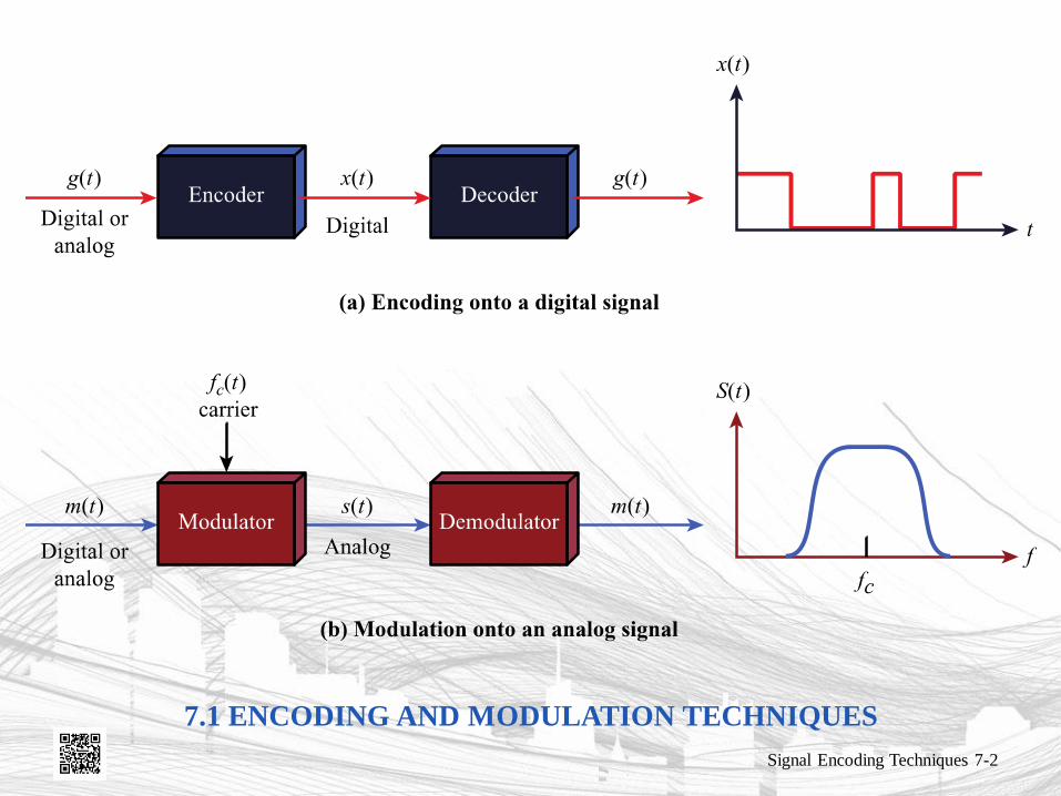
REASONS FOR CHOOSING
ENCODING TECHNIQUES
• Digital data, digital signal
– Equipment less complex and expensive than
digital-to-analog modulation equipment
• Analog data, digital signal
– Permits use of modern digital transmission and
switching equipment
Signal Encoding Techniques 7-3
REASONS FOR CHOOSING
ENCODING TECHNIQUES
• Digital data, analog signal
– Some transmission media will only propagate analog signals
– E.g., optical fiber and unguided media
• Analog data, analog signal
– Analog data in electrical form can be transmitted easily and cheaply
– Done with voice transmission over voice-grade lines
Signal Encoding Techniques 7-4
SIGNAL ENCODING CRITERIA
• What determines how successful a receiver will be in interpreting an incoming signal?
– Signal-to-noise ratio
– Data rate
– Bandwidth
• An increase in data rate increases bit error rate
• An increase in SNR decreases bit error rate
• An increase in bandwidth allows an increase in data rate
Signal Encoding Techniques 7-5
FACTORS USED TO COMPARE
ENCODING SCHEMES
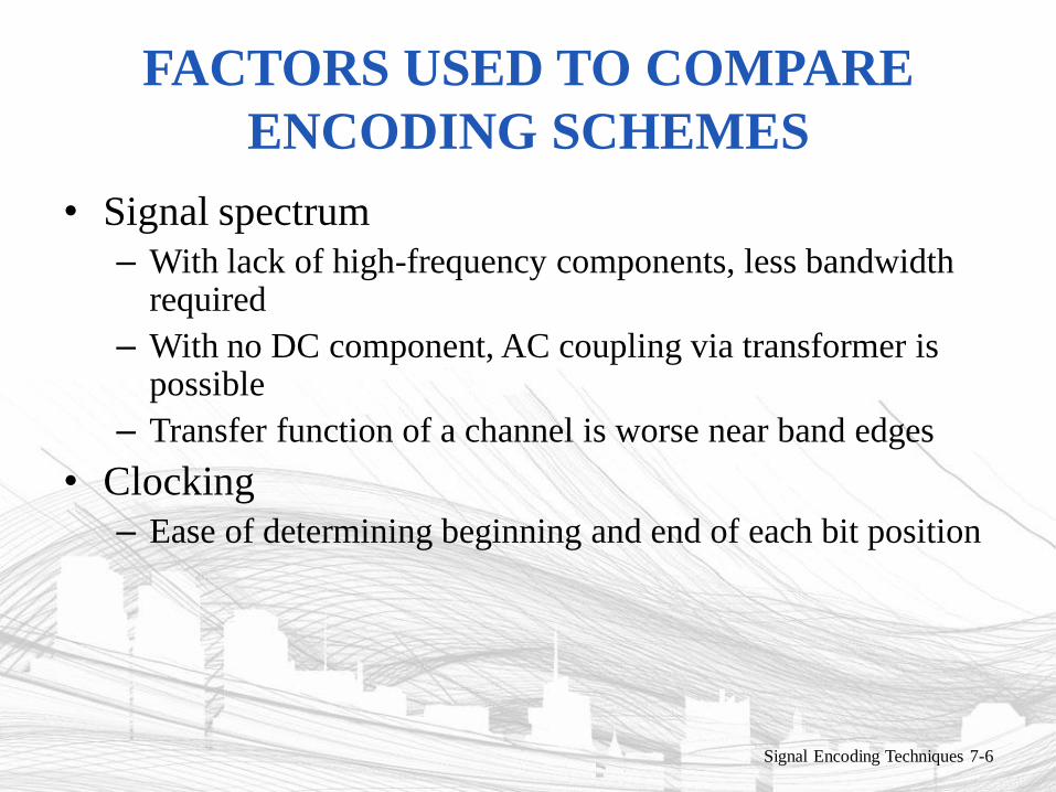
• Signal spectrum
– With lack of high-frequency components, less bandwidth required
– With no DC component, AC coupling via transformer is possible
– Transfer function of a channel is worse near band edges
• Clocking
– Ease of determining beginning and end of each bit position
Signal Encoding Techniques 7-6
FACTORS USED TO COMPARE
ENCODING SCHEMES
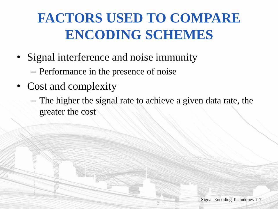
• Signal interference and noise immunity
– Performance in the presence of noise
• Cost and complexity
– The higher the signal rate to achieve a given data rate, the
greater the cost
Signal Encoding Techniques 7-7
BASIC ENCODING TECHNIQUES
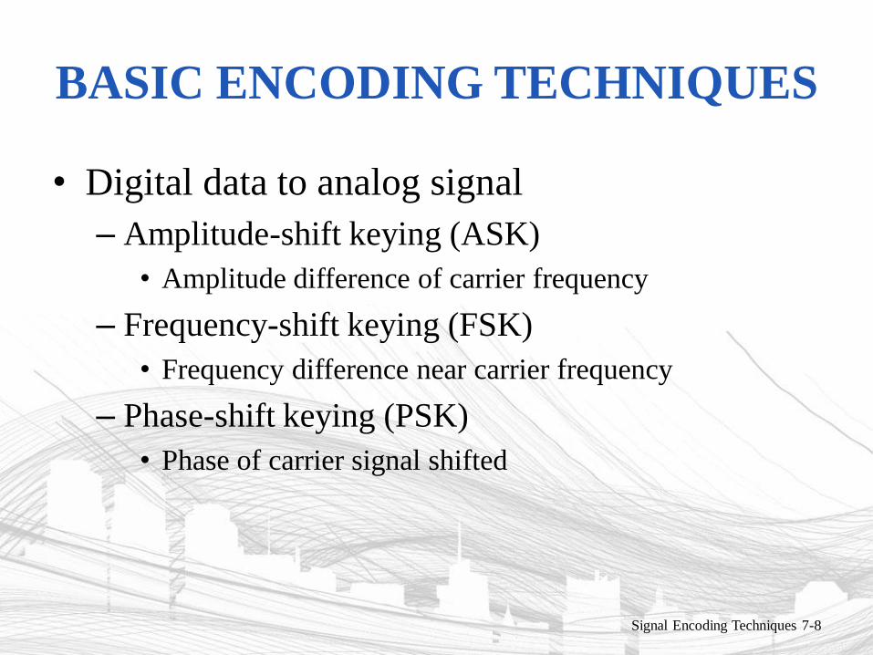
• Digital data to analog signal
– Amplitude-shift keying (ASK)
• Amplitude difference of carrier frequency
– Frequency-shift keying (FSK)
• Frequency difference near carrier frequency
– Phase-shift keying (PSK)
• Phase of carrier signal shifted
Signal Encoding Techniques 7-8
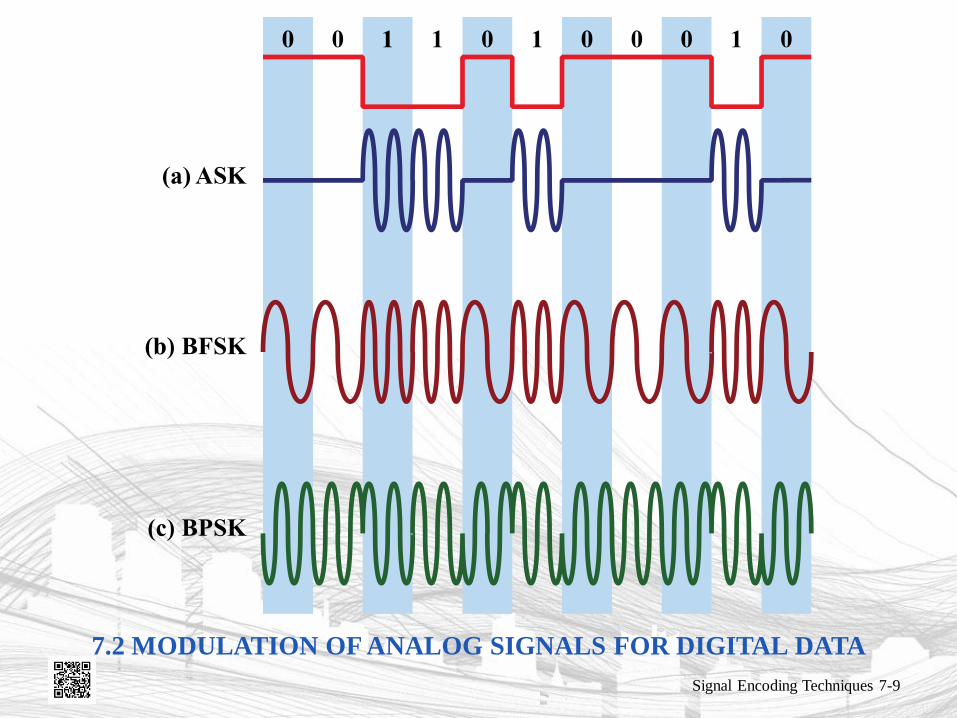
7.2 MODULATION OF ANALOG SIGNALS FOR DIGITAL DATA
Signal Encoding Techniques 7-9
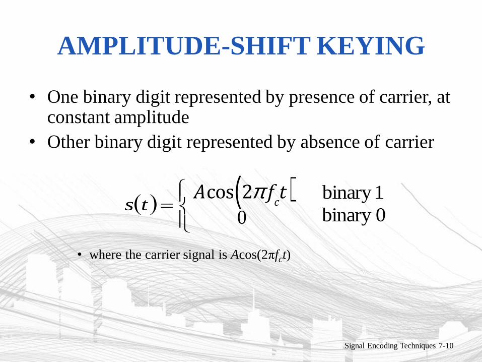
AMPLITUDE-SHIFT KEYING
• One binary digit represented by presence of carrier, at constant amplitude
• Other binary digit represented by absence of carrier
• where the carrier signal is Acos(2πfct)
Signal Encoding Techniques 7-10
ts Acos 2p f
ct( )
0
1binary
0binary
AMPLITUDE-SHIFT KEYING
• Susceptible to sudden gain changes
• Inefficient modulation technique
• Used to transmit digital data over optical fiber
Signal Encoding Techniques 7-11
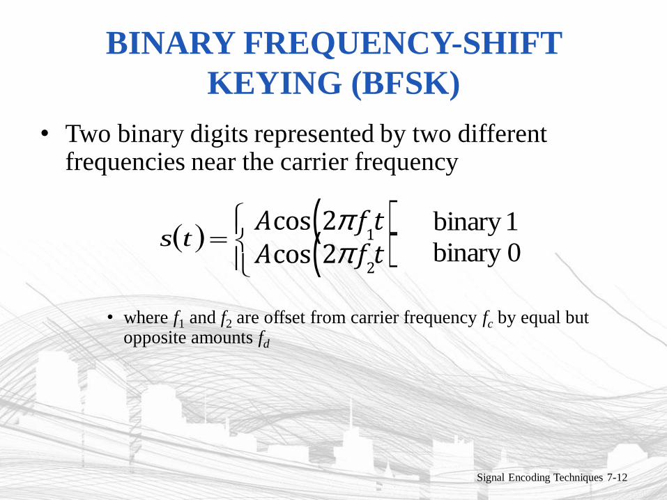
BINARY FREQUENCY-SHIFT
KEYING (BFSK)
• Two binary digits represented by two different frequencies near the carrier frequency
• where f1 and f2 are offset from carrier frequency fc by equal but opposite amounts fd
Signal Encoding Techniques 7-12
ts Acos 2p f
1t( )
Acos 2p f
2t( )
1binary
0binary
BINARY FREQUENCY-SHIFT
KEYING (BFSK)
• Less susceptible to error than ASK
• Used for high-frequency (3 to 30 MHz) radio
transmission
• Can be used at higher frequencies on LANs
that use coaxial cable
Signal Encoding Techniques 7-13
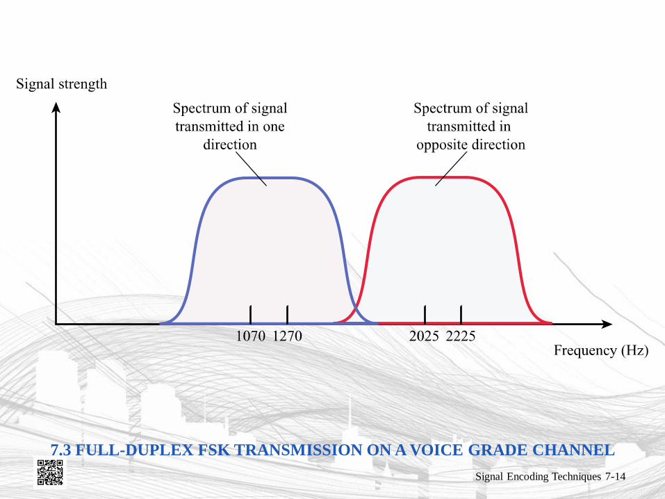
7.3 FULL-DUPLEX FSK TRANSMISSION ON A VOICE GRADE CHANNEL
Signal Encoding Techniques 7-14
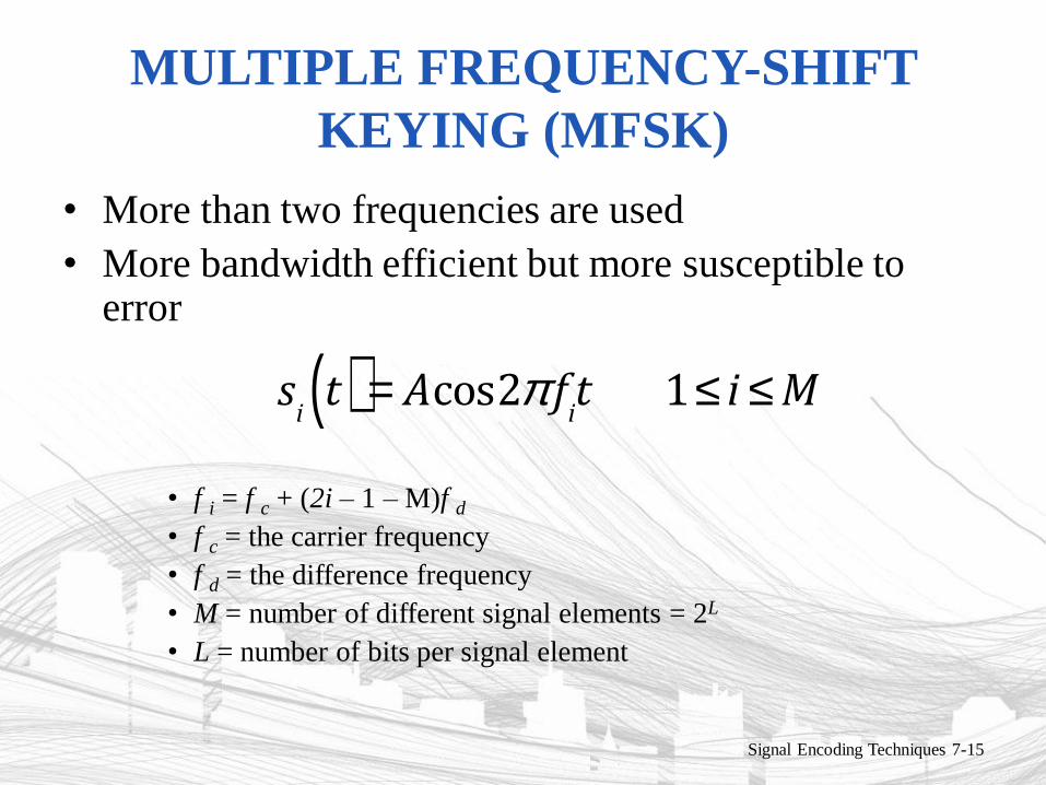
MULTIPLE FREQUENCY-SHIFT
KEYING (MFSK)
• More than two frequencies are used
• More bandwidth efficient but more susceptible to error
• f i = f c + (2i – 1 – M)f d
• f c = the carrier frequency
• f d = the difference frequency
• M = number of different signal elements = 2L
• L = number of bits per signal element
Signal Encoding Techniques 7-15
s
it( ) = Acos2p f
it 1£ i £ M
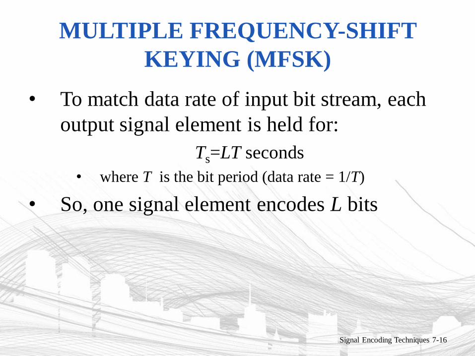
MULTIPLE FREQUENCY-SHIFT
KEYING (MFSK)
• To match data rate of input bit stream, each
output signal element is held for:
Ts=LT seconds
• where T is the bit period (data rate = 1/T)
• So, one signal element encodes L bits
Signal Encoding Techniques 7-16
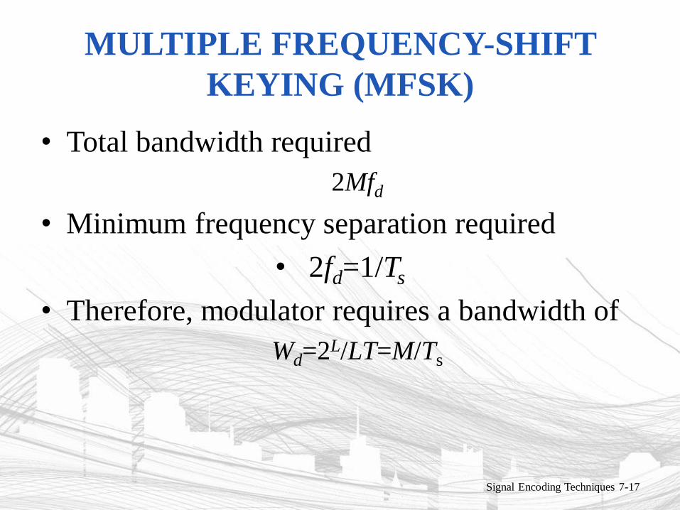
MULTIPLE FREQUENCY-SHIFT
KEYING (MFSK)
• Total bandwidth required
2Mfd
• Minimum frequency separation required
• 2fd=1/Ts
• Therefore, modulator requires a bandwidth of
Wd=2L/LT=M/Ts
Signal Encoding Techniques 7-17
PHASE-SHIFT KEYING (PSK)
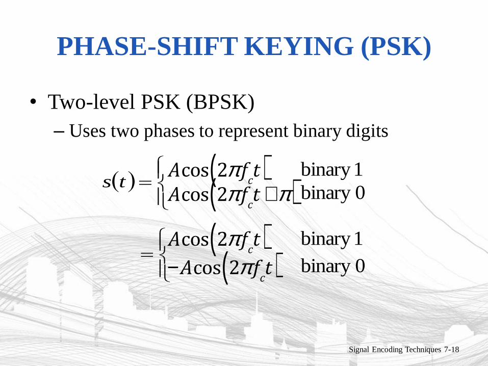
• Two-level PSK (BPSK)
– Uses two phases to represent binary digits
Signal Encoding Techniques 7-18
ts Acos 2p f
ct( )
Acos 2p f
ct +p( )
1binary
0binary
Acos 2p f
ct( )
-Acos 2p f
ct( )
1binary
0binary
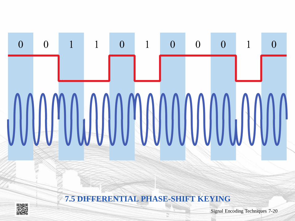
PHASE-SHIFT KEYING (PSK)
• Differential PSK (DPSK)
– Phase shift with reference to previous bit
• Binary 0 – signal burst of same phase as previous signal
burst
• Binary 1 – signal burst of opposite phase to previous
signal burst
Signal Encoding Techniques 7-19
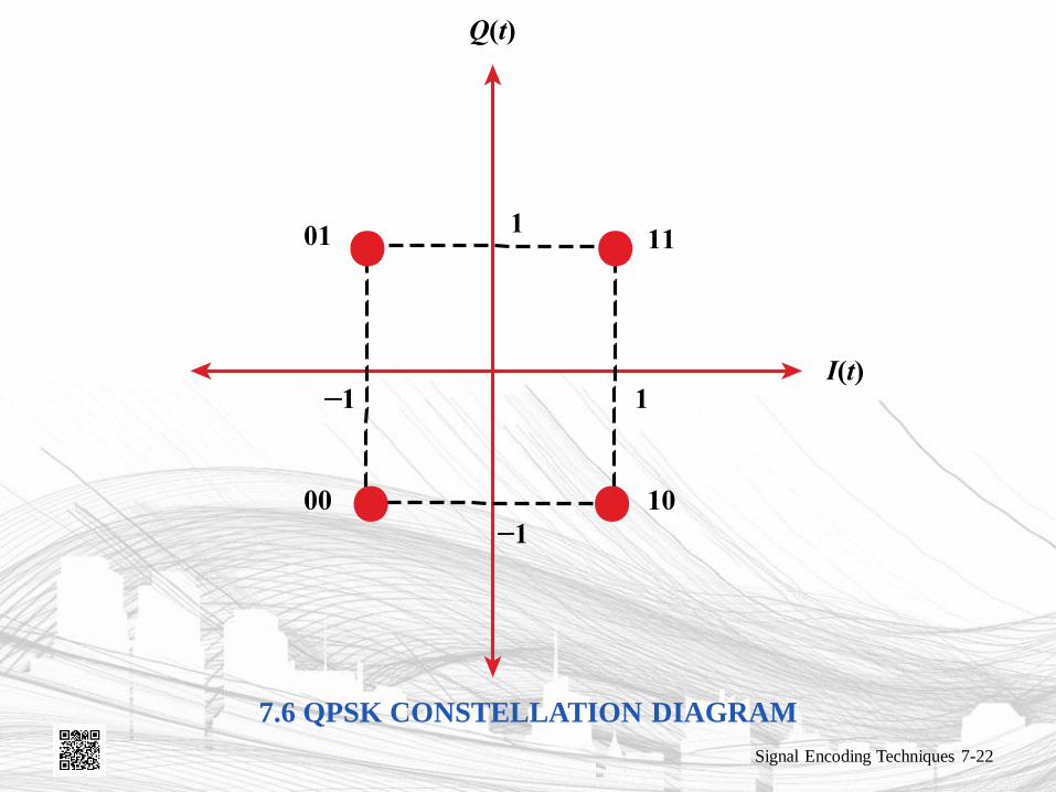
QUADRATURE PHASE-SHIFT
KEYING (PSK)
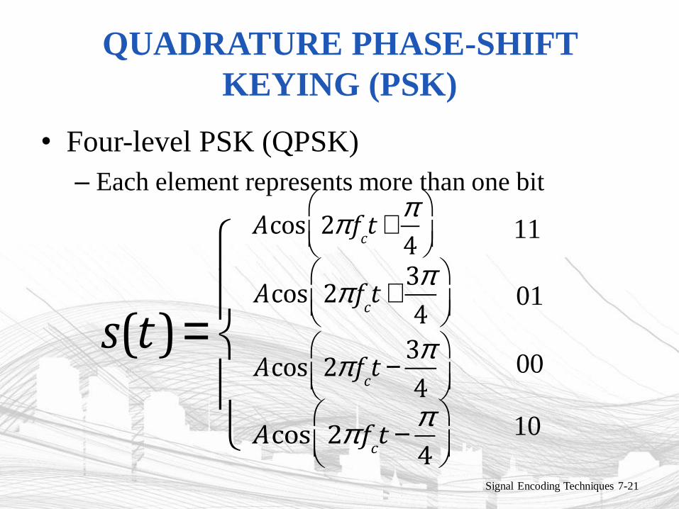
• Four-level PSK (QPSK)
– Each element represents more than one bit
Signal Encoding Techniques 7-21
s(t)=
ì
íï
îï
Acos 2p fct +
p
4
æ
èçö
ø÷11
Acos 2p fct +
3p
4
æ
èçö
ø÷
Acos 2p fct -
3p
4
æ
èçö
ø÷
Acos 2p fct -
p
4
æ
èçö
ø÷
01
00
10

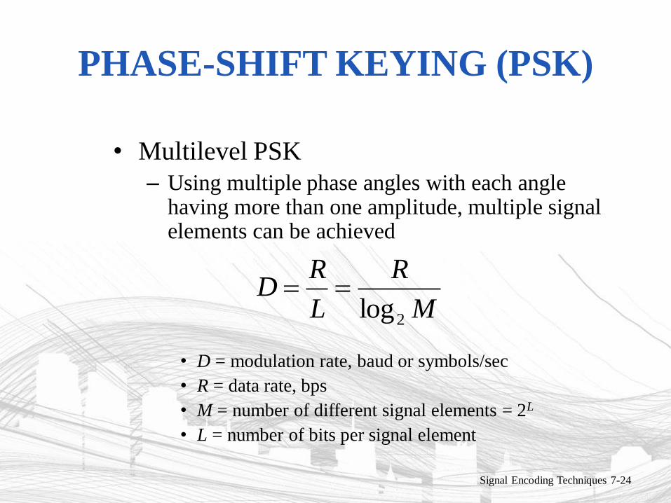
PHASE-SHIFT KEYING (PSK)
• Multilevel PSK
– Using multiple phase angles with each angle having more than one amplitude, multiple signal elements can be achieved
• D = modulation rate, baud or symbols/sec
• R = data rate, bps
• M = number of different signal elements = 2L
• L = number of bits per signal element
Signal Encoding Techniques 7-24
M
R
L
RD
2log
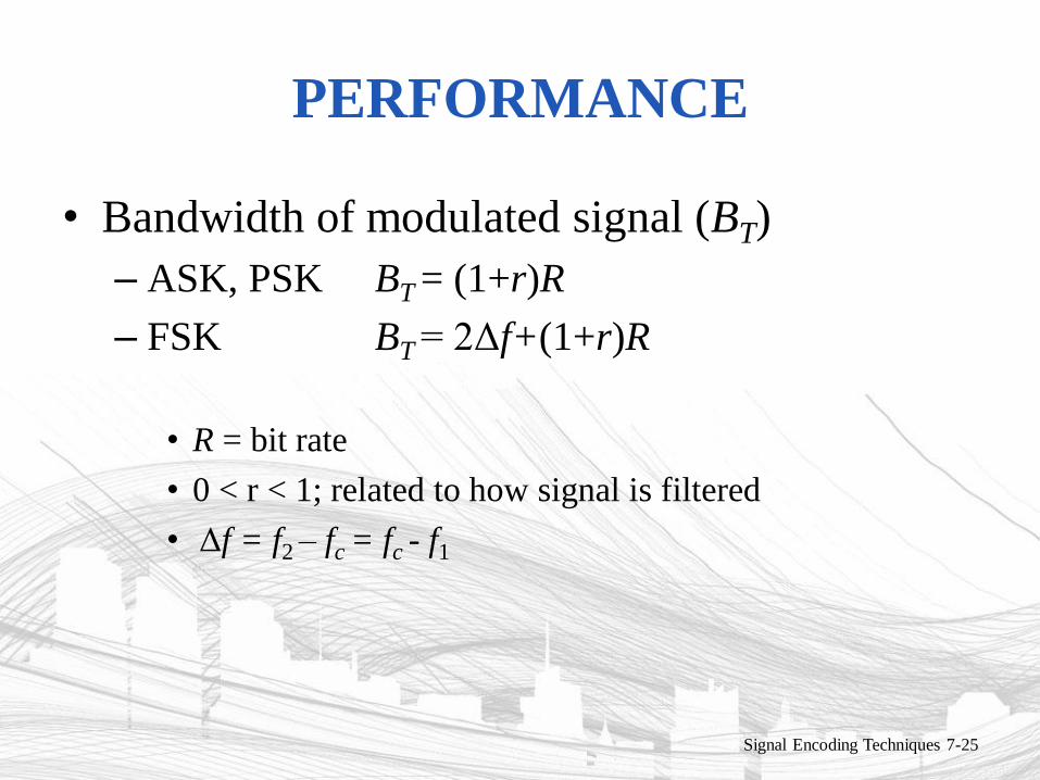
PERFORMANCE
• Bandwidth of modulated signal (BT)
– ASK, PSK BT = (1+r)R
– FSK BT = 2Δf+(1+r)R
• R = bit rate
• 0 < r < 1; related to how signal is filtered
• Δf = f2 – fc = fc - f1
Signal Encoding Techniques 7-25
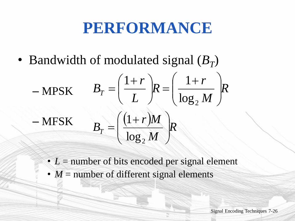
PERFORMANCE
• Bandwidth of modulated signal (BT)
– MPSK
– MFSK
• L = number of bits encoded per signal element
• M = number of different signal elements
Signal Encoding Techniques 7-26
RM
rR
L
rBT
2log
11
R
M
MrBT
2log
1
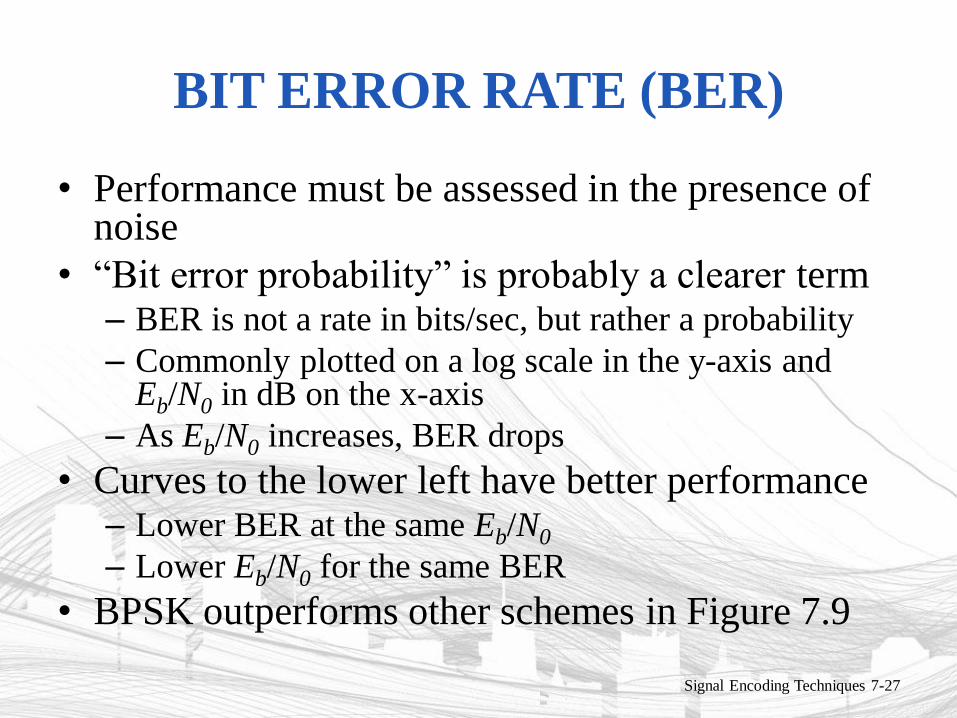
BIT ERROR RATE (BER)
• Performance must be assessed in the presence of noise
• “Bit error probability” is probably a clearer term – BER is not a rate in bits/sec, but rather a probability
– Commonly plotted on a log scale in the y-axis and Eb/N0 in dB on the x-axis
– As Eb/N0 increases, BER drops
• Curves to the lower left have better performance – Lower BER at the same Eb/N0
– Lower Eb/N0 for the same BER
• BPSK outperforms other schemes in Figure 7.9
Signal Encoding Techniques 7-27
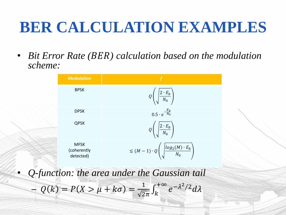
BER CALCULATION EXAMPLES
• Bit Error Rate (𝐵𝐸𝑅) calculation based on the modulation scheme:
• Q-function: the area under the Gaussian tail
– 𝑄 𝑘 = 𝑃 𝑋 > 𝜇 + 𝑘𝜎 =1
2𝜋 𝑒−𝜆
2/2𝑑𝜆+∞
𝑘
Modulation 𝒇
BPSK
𝑄2 ∙ 𝐸𝑏𝑁0
DPSK 0.5 ∙ 𝑒
−𝐸𝑏𝑁0
QPSK
𝑄2 ∙ 𝐸𝑏𝑁0
MFSK (coherently detected)
≤ (𝑀 − 1) ∙ 𝑄𝑙𝑜𝑔2(𝑀) ∙ 𝐸𝑏
𝑁0
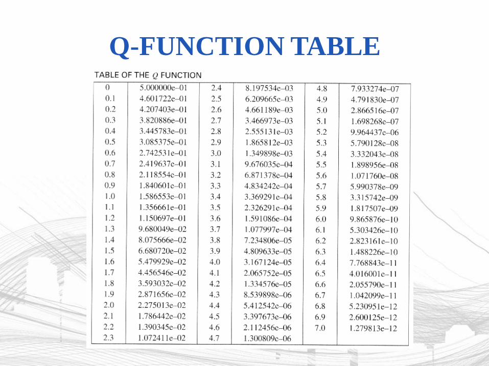
Q-FUNCTION TABLE
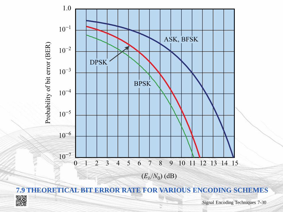
7.9 THEORETICAL BIT ERROR RATE FOR VARIOUS ENCODING SCHEMES
Signal Encoding Techniques 7-30
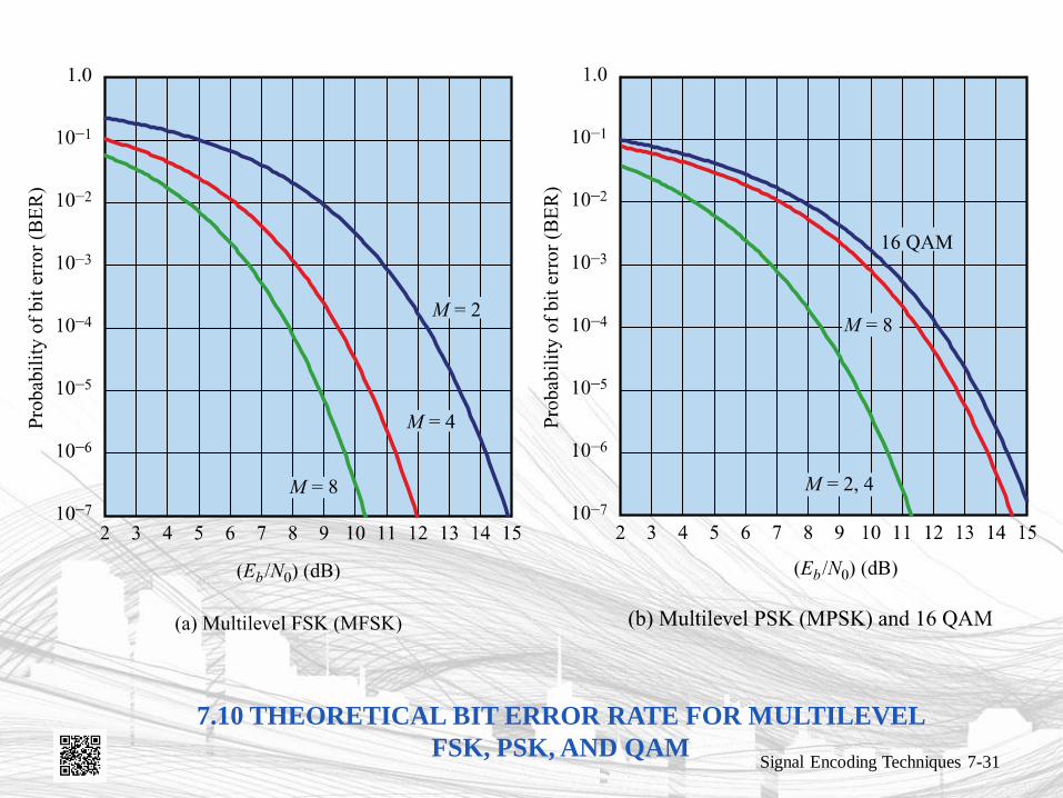
7.10 THEORETICAL BIT ERROR RATE FOR MULTILEVEL
FSK, PSK, AND QAM Signal Encoding Techniques 7-31
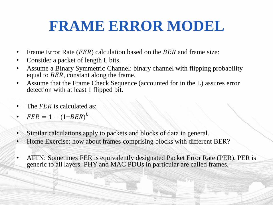
FRAME ERROR MODEL
• Frame Error Rate (𝐹𝐸𝑅) calculation based on the 𝐵𝐸𝑅 and frame size:
• Consider a packet of length L bits.
• Assume a Binary Symmetric Channel: binary channel with flipping probability equal to 𝐵𝐸𝑅, constant along the frame.
• Assume that the Frame Check Sequence (accounted for in the L) assures error detection with at least 1 flipped bit.
• The 𝐹𝐸𝑅 is calculated as:
• 𝐹𝐸𝑅 = 1 − (1−𝐵𝐸𝑅)𝐿
• Similar calculations apply to packets and blocks of data in general.
• Home Exercise: how about frames comprising blocks with different BER?
• ATTN: Sometimes FER is equivalently designated Packet Error Rate (PER). PER is generic to all layers. PHY and MAC PDUs in particular are called frames.
RECEIVER SENSITIVITY
• The minimum RF signal power level required at the input of a receiver for certain performance (e.g. BER or FER)
• E.g., IEEE 802.11 standard considers a maximum acceptable FER < 1% for 20-octet Physical layer Service Data Units (PSDUs), without interference.
• In order to simplify system analysis, it is considered that reception power below the receiver sensitivity does not allow communication.
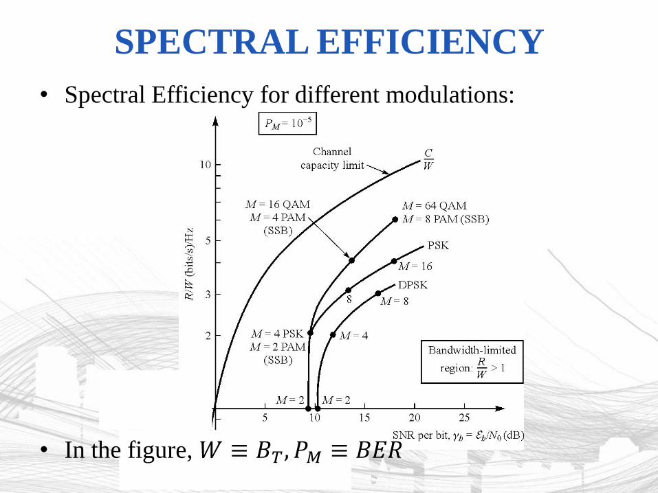
• Spectral Efficiency for different modulations:
• In the figure, 𝑊 ≡ 𝐵𝑇, 𝑃𝑀 ≡ 𝐵𝐸𝑅
SPECTRAL EFFICIENCY
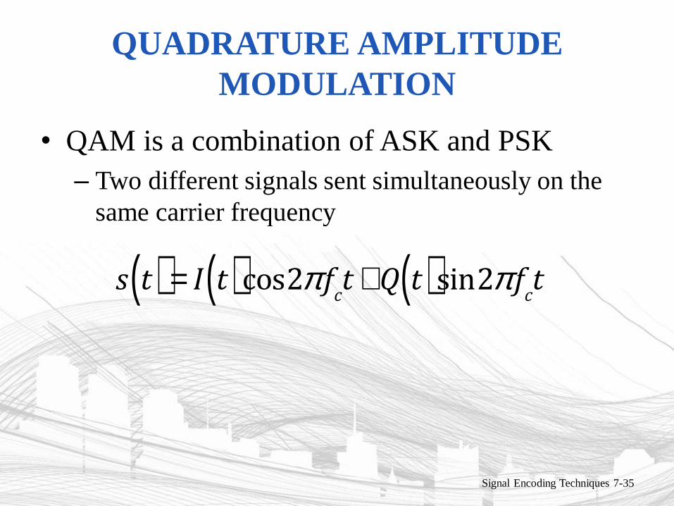
QUADRATURE AMPLITUDE
MODULATION
• QAM is a combination of ASK and PSK
– Two different signals sent simultaneously on the
same carrier frequency
Signal Encoding Techniques 7-35
s t( ) = I t( )cos2p f
ct +Q t( )sin2p f
ct
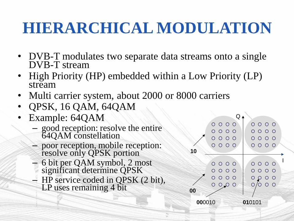
HIERARCHICAL MODULATION
• DVB-T modulates two separate data streams onto a single DVB-T stream
• High Priority (HP) embedded within a Low Priority (LP) stream
• Multi carrier system, about 2000 or 8000 carriers • QPSK, 16 QAM, 64QAM • Example: 64QAM
– good reception: resolve the entire 64QAM constellation
– poor reception, mobile reception: resolve only QPSK portion
– 6 bit per QAM symbol, 2 most significant determine QPSK
– HP service coded in QPSK (2 bit), LP uses remaining 4 bit
Q
I
00
10
000010 010101
REASONS FOR ANALOG
MODULATION
• Modulation of digital signals
– When only analog transmission facilities are available, digital to analog conversion required
• Modulation of analog signals
– A higher frequency may be needed for effective transmission
– Modulation permits frequency division multiplexing
Signal Encoding Techniques 7-39
BASIC ENCODING TECHNIQUES
• Analog data to analog signal
– Amplitude modulation (AM)
– Angle modulation
• Frequency modulation (FM)
• Phase modulation (PM)
Signal Encoding Techniques 7-40