chapter 7 farm - usda · chapter 7 farm distribution components contents ... possible without...
TRANSCRIPT

Chapter 7 Farm Distribution Components
Contents: FL652.0700 General FL7-1
FL652.0701 Pipelines FL7-1 (a) Typical pipe installation and materials for irrigation systems FL7-2 (i) Culverts FL7-2 (ii) Gravity pipelines FL7-2 (iii) Pumped pressure pipelines FL7-2 (b) Specific applications FL7-2 (c) Pipeline design considerations FL7-3 (i) Water hammer FL7-3 (ii) Safety devices FL7-3 (iii) Accessories FL7-6
FL652.0702 Open ditches FL7-6 (a) Unlined ditches FL7-6 (b) Seepage losses FL7-7
FL652.0703 Water control structures FL7-7 (a) Related structures for open ditches FL7-7 (i) Flumes FL7-7 (ii) Siphons FL7-8 (iii) Inverted siphons FL7-8 (iv) Culverts FL7-8 (v) Grade control structures FL7-8 (vi) Distribution structures and devices FL7-9 (b) Related structures for gravity pipelines FL7-9 (c) Related structures for pumped pipelines FL7-9 (d) Thrust block requirements for thermoplastic irrigation FL7-10 (i) Definition FL7-10 (ii) Conditions where thrust blocks apply FL7-10 (iii) Location FL7-10 (iv) Design criteria FL7-10 (v) Construction requirements FL7-11
FL652.0704 Water measurement FL7-14 (a) Planning and design considerations FL7-14 (i) Open ditch flow FL7-14 (ii) Pipe flow FL7-15
(210-vi-NEH, Amendment FL-13, May 2007) FL7-i

Chapter 7 Farm Distribution Components Part 652 Irrigation Guide
FL652.0705 Irrigation runoff, tailwater recovery and reuse FL7-16 (a) Planning and design considerations FL7-16 (i) Storage FL7-16 (ii) Pumps FL7-18 (iii) Sizing for runoff FL7-18
FL652.0706 Irrigation system automation FL7-21 (a) Planning and design considerations for automation FL7-21 (i) Automatic systems FL7-21 (ii) Semiautomatic systems FL7-21 (iii) Communications FL7-22 (iv) Surface irrigation system automation FL7-22 (v) Sprinkler and micro irrigation systems FL7-22
FL652.0707 Pumping plants FL7-23
FL652.0708 Drainage systems FL7-27 (a) Precipitation runoff FL7-28 (b) Irrigation runoff (tailwater) FL7-28 (c) Subsurface drainage FL7-28 (i) Interceptor drains FL7-29 (ii) Relief drains FL7-29 (iii) Pumped drains FL7-29 (d) Environmental factors FL7-29 (i) Wetlands FL7-29 (ii) Water quality FL7-29
FL652.0709 Chemigation FL7-29 (a) Advantages FL7-30 (b) Disadvantages FL7-30 (c) Planning and design considerations FL7-30 (i) Chemical injection equipment FL7-31 (ii) Safety equipment FL7-34 (iii) Fertilizer application FL7-38
Tables FL7-1 Allowable soil bearing pressure FL7-11
FL7-2 Expected recovery from runoff FL7-19
FL7-3 Tailwater pit sizing for intermittent pumpback facility FL7-20
FL7-4 Overall efficiencies obtainable by using tailwater recovery and reuse facility
FL7-20
FL7-ii (210-vi-NEH, Amendment FL-13, May 2007)

Chapter 7 Farm Distribution Components Part 652 Irrigation Guide
FL7-5 Liquid fertilizers (solutions) for sprinkler application FL7-39
FL7-6 Dry fertilizers for sprinkler application FL7-40
FL7-7 Comparison of typical analysis of clear suspension-type liquid fertilizers
FL7-41
Figures FL7-1 Illustration of valve locations FL7-5
FL7-2 Cross-section of trench wall FL7-12
FL7-3 Location of thrust blocks FL7-13
FL7-4 Typical tailwater collection and reuse facility for quick-cycling pump and reservoir
FL7-17
FL7-5 Filtration operation FL7-25 FL7-6 Backwash operation FL7-25 FL7-7 Screen filter with interior flow FL7-25 FL7-8 Screen filter with exterior flow FL7-26 FL7-9 Through flush screen filter cleaning FL7-26
FL7-10 Backwash screen filter cleaning FL7-26
FL7-11 Gravity flow from storage tank FL7-31
FL7-12 Injection on suction side of pump FL7-32
FL7-13 Venturi principle of injection FL7-33
FL7-14 Pitot tube injection FL7-33
FL7-15 Pressure metering pump injection FL7-34
FL7-16 Single anti-siphon device assembly FL7-36
FL7-17 Double anti-siphon device assembly FL7-36
FL7-18 Safety devices for injection of chemicals into pressurized irrigation systems using electric power
FL7-37
FL7-19 Safety devices for injection of chemicals into pressurized irrigation systems using internal combustion engine power
FL7-38
(210-vi-NEH, Amendment FL-13, May 2007) FL7-iii

Chapter 7 Farm Distribution Components Part 652 Irrigation Guide
FL652.0700 General
Irrigation water should be made available to each part of the farm irrigation system at a rate and elevation or pressure that permits proper operation of irrigation application devices or facilities. Irrigation water should be conveyed as economically, efficiently, and safely as possible without excessive losses or erosion. Water should be delivered to the plant at a suitable quality for the planned purpose. All components of a farm irrigation water delivery system must be sized to furnish adequate irrigation water to meet planned crop use. Plans should provide for future needs and expansion.
Sizing an irrigation system to meet peak (or planned) period crop water use requires careful consideration of many alternatives and compromises. They involve ditch and pipe size, pump size, labor considerations, capital investment, operating costs, available water capacity of soils, crop rotations, plant stress risk levels, and overall management of the farm enterprise. Providing water, along with irrigation water management, to meet crop needs 80 percent or even 50 percent of the time can be more economical than providing full irrigation for all conditions.
Water delivery should be adaptable to meet specific crop water needs for each irrigation system used. Basic components of distribution systems include pipelines, unlined and lined open ditches, water control structures, water measurement devices, tailwater recovery and reuse facilities, system automation, pumping plants, surface drainage systems, and chemical storage, injection and transport facilities.
Farm distribution components (facilities) include all necessary appurtenances, such as water control structures, slide gates, trash racks, screening devices, water measuring devices, flow control valves, air release valves, vacuum relief valves, pressure regulating or relief valves, controllable flow turnouts and drains, plus other components necessary for the long-term operation and maintenance of the system. All facilities should be located so they interfere as little as possible with farming operations.
Components of the distribution system should be readily accessible for operation and maintenance. An operation and maintenance plan should be provided as part of the system plan or design.
Design criteria, procedures, friction loss tables and charts, and design examples are provided in Natural Resources Conservation Service (NRCS) references including National Engineering Handbook (NEH) Part 634 (Section 3), Hydraulics; NEH Part 623 (Section 15), Irrigation; National Engineering Field Handbook, Chapters 3, Hydraulics, and 15, Irrigation; and several design notes and technical releases. Several computer programs have been developed for Florida to assist in the design of pipelines, the evaluation of center pivot and microirrigation systems, and in the preparation of irrigation water management plans. These programs are available for use and can be downloaded from the Florida NRCS website, http://www.fl.nrcs.usda.gov/technical/program.html. Other references, tools, and programs commonly used are included in Chapter 15, Resource Planning and Evaluation Tools and Worksheets.
FL652.0701 Pipelines
Pipeline delivery systems can be pumped or gravity flow and consist of buried pipe, surface installed pipe, or both. A buried pipe can extend from a water source to the farm and to individual fields with surface pipe used for distribution within the field. Buried pipe can also extend into fields as a field main (or submain) and have risers and valves appropriately spaced to deliver water to surface ditches, portable water conveyance pipelines, gated pipe, or sprinkler laterals.
(210-vi-NEH, Amendment FL-13, May 2007) FL7-1

Chapter 7 Farm Distribution Components Part 652 Irrigation Guide (a) Typical pipe installation and materials for an irrigation system:
(i) Culverts Culverts are generally short pipe sections where partial pipe flow conditions exist. Typical use includes: • Equipment crossings in open channels
(canals, laterals, ditches). • Water control structures with flow control
gate installation. • Water measuring.
Materials are generally galvanized steel or aluminum corrugated metal pipe; PVC plastic pipe; corrugated polyethylene (regular or smooth bore) plastic pipe; and reinforced or non-reinforced concrete pipe.
(ii) Gravity pipelines Generally gravity pressure pipelines are longer pipe sections where full pipe flow, partial pipe flow, or a combination of both conditions exist. They rely on elevation drop to provide sufficient hydraulic gradient for flow to occur. Gravity pipelines are used to transport water in a conveyance or distribution system, or from a source to point of use, as buried or surface, permanent or portable pipes. Typical use includes:
• Water conveyance pipelines to reduce seepage and evaporation losses, prevent erosion, or provide control of water delivery.
• Inverted siphons to replace flumes or to cross low areas including gullies.
• Gated pipe to distribute water into furrows. • Pipelines to provide gravity pressure for
sprinkler or micro irrigation systems.
Materials are generally plastic, welded steel, galvanized steel, reinforced or non-reinforced concrete, reinforced fiber glass, or aluminum.
(iii) Pumped pressure pipelines Pumped pressure pipelines can be buried or surface installed. Generally longer sections are used where full pipe flow conditions exist and shorter sections where water is pumped from a source (pond, canal, stream, and/or well) to an open ditch that is close. A pump is used to provide adequate pressure head to overcome
elevation and pipe and fitting friction losses. Pipelines can be permanent or portable. They are used to transport water in a conveyance and distribution system or from source to point of use. Typical use includes:
• Pipe within a pumping plant system that lifts water from source to open ditch or field.
• Conveyance and distribution system. • Pipelines to contain pressurized flows for use
in sprinkler, subsurface and micro irrigation systems.
Materials are generally welded steel, galvanized steel, aluminum, or plastic.
(b) Specific applications
Gated pipe is a surface portable pipe (generally PVC or aluminum) used to distribute controlled flows to furrows at very low pressure head (< 1 to 2 lb/in2). Disposable, thin wall (7 or 10 mil), lay-flat PE pipe is also available. Its use is generally limited to 1 or 2 years. With the pipeline filled with water, a hand punch mounted on a handle, approximately 2 feet long, is moved in an arc to create holes (or gates) at each furrow. Hole sizes are selected to discharge predetermined amounts of water at each furrow, based on head available in the pipeline. Pipeline grades can be established where only two or three hole sizes are necessary in a quarter-mile pipeline. Maximum head (pressure) in lay-flat PE pipe must be less than 10 feet (4 psi).
Gated pipe can be used in place of an open head ditch at the upper end of a field. It is also well suited to use in place of an intermediate temporary head ditch on fields too long to be irrigated in one length of run. Socks or other devices attached to each gate help to reduce exit velocities; thereby minimizing erosion at the head of furrows. The degree the gates are opened accurately regulates water flow to each furrow. Where water source to the gated pipe is from open ditches, screening for debris removal may be necessary to prevent plugging of gate openings. Gated pipe is used in cablegation and surge systems. Once gated pipe is installed at the head of the fields for the duration of the
FL7-2 (210-vi-NEH, Amendment FL-13, May 2007)

Chapter 7 Farm Distribution Components Part 652 Irrigation Guide
irrigation season and the gates are adjusted, additional labor is rarely necessary.
The most common problem with gated pipe is having excess pressure head. Excess pressure head accelerates pipeline leakage at the joints and furrow erosion immediately downstream of gates. Easy to install devices are available to reduce pressure head. These can be installed inside the pipe as controllable low head gates or outside the pipe as flow-through stands or boxes.
When disposable PE pipe is used, the pipeline is laid out, filled with water, and predetermined sized holes punched for each irrigated furrow. When reinforced PVC lay-flat pipe is used, adjustable gates can be inserted in the holes. Typically two or more hole sizes are required across the field to deliver a design flow rate to each furrow (or border strip). Very low pressure head is used in the pipelines, thus friction loss and elevation differences become critical.
(c) Pipeline design considerations
This section is to provide guidance for the planning and design of distribution pipelines used in irrigation systems.
(i) Water hammer One of the most detrimental factors contributing to pipe failures in distribution pipelines is water hammer or surge. In a pipe containing a column of moving liquid, energy is stored in the fluid due to its mass and velocity. When a valve is quickly closed, the velocity is suddenly stopped. Since liquids are nearly incompressible, this energy cannot be absorbed and the momentum of the fluid causes a shock called water hammer. This may cause excessively high water momentary pressures. The shutting down and restarting of a pump before the system comes to rest is also a cause of excessive surge pressure. The four factors that determine water hammer are the length of pipeline (the longer the pipeline, the greater the shock), velocity, the closing time of valves, and the diameter of pipe.
Since velocity is the primary factor contributing to excessive water hammer, velocity of pipeline should be limited to 5 ft/sec. Irrigators should also be advised against quick closing of valves
and restarting pumps before the system returns to static rest.
(ii) Safety devices There are many safety devices available that enhance the water delivery process and protect the pipeline investment. The relative location of each of these devices is important and alteration of their location should be reviewed carefully. Refer to Figure FL7-1 for an illustration of valve locations.
Manual valves are primarily used to isolate sections of an irrigation system for repair. In order to keep friction to a minimum, the valves should be gate valves. Generally, cross handles are preferred as the access to gate valves is through valve sleeves. A sprinkler control valve key is used to open them. Non-rising stems are often required. A gate valve is occasionally used as flow control, but its use is limited to hydraulically simple systems.
Check valves are used to limit water flow to one direction. Check valves are utilized at the pump discharge to prevent backflow water into the well and are required to prevent chemicals from flowing back into the ground water when chemical injection is used.
Check valves can be swing check, spring-loaded, or float. The primary use of check valves is to keep water in sloped pipelines from draining out the low head on the section. By blocking the lowest exit, the water remains in the pipe and a flooding condition around the low head is prevented. Also, by keeping water in the lines of a block system, trapped air is minimized which then minimizes the potential for hydraulic ram when section valves are opened.
Pressure reducing valves provide control over the downstream flow rate and/or pressure. These control valves are often used to prevent rapid build up of line pressures during pump start-up.
Anti-siphon or backflow prevention units are specifically for the protection of domestic water when irrigation lines use domestic water as a source.
An atmospheric vacuum-breaker uses a float principal to seal against water backflow with
(210-vi-NEH, Amendment FL-13, May 2007) FL7-3

Chapter 7 Farm Distribution Components Part 652 Irrigation Guide backflow directed to atmosphere. Since most municipal building codes require one of these units downstream of each sprinkler control valve, it is not possible to place sprinklers or pipe higher than the anti-siphon device as water in the line would drain out every time the sprinklers were turned off.
Pressure vacuum breakers are spring-loaded, anti-siphon devices that require pressure to open and are vented to the atmosphere. Although most building codes allow one of these units prior to any sprinkler control valve, water can drain back through the device if the pipe is higher than the device. The size is usually limited to an inside diameter of 2-inches (2-inch I.P.S.).
Double-check valve assemblies with or without gate valves on each end and a pressure type vacuum breaker are sometimes used when the supply line is too large for the pressure vacuum breaker to be in line, either singularly or parallel.
The only method of backflow prevention that can be used when the supply line of the unit is lower than the pipe or sprinklers is the reduced pressure backflow preventer. This is used when cross connections with contaminated water are required. It is generally recommended to seek an alternative method of supplying water to the site rather than require a reduced pressure backflow preventer. This can be done by gravity flowing water into a reservoir and pumping from the reservoir into the irrigation system.
Drain valves can either be manual or automatic and are only used on systems in freezing climates to drain the water from the pipelines to prevent the lines from bursting. Manual drain valves are usually used on distribution lines that are continually under pressure. When the system is winterized, the valve is opened and water drained from the pipes. Pressurized air is also often introduced at other points of the system to clear out any pockets of water caused by low pipelines. Manual drain valves are normally located at lower points of the system and should be an angle valve which incorporates a flexible and replaceable seat.
Automatic drain valves are typically a spring and ball combination and are used in lateral lines
that are under pressure only when sprinklers are operating. When the water pressure in the pipe reduces, the spring is relieved of the pressure contracting it; it expands, pushing the ball off the seat to allow water to flow through it to the atmosphere.
Pressure regulating valves are used when water pressure exceeds that desired. In areas where the topography varies greatly, the pressure build-up can be in excess of what is needed for proper operation of an irrigation system. Pressure regulators are used to reduce the pressure.
The pressure regulator has a fluctuating passage which can induce a pressure loss. The greater the demand for water, the less pressure loss is induced as there is a natural pressure loss in the piping prior to the pressure regulator. Under low demands, the regulator induces a greater pressure loss. Most pressure regulators have a range of pressures for setting the pressure.
Pressure release valves act to protect the pipeline from excessive pressure. It is installed between the pump discharge and the pipeline if excessive pressure can build up when all valves are closed. Pressure release valves shall be installed on the discharge side of the check valve where a reversal of flow may occur and at the end of the pipeline if needed to relieve surge at the end of the line.
Air valves are for liquid systems and not for air or gas systems. An air-release valve will automatically release accumulated small pockets of air from high points in a system while that system is in operation and under pressure.
Naturally, some of the air entrained in a system will settle out of the liquid being pumped and collect at high points within that system. If no provision is made to remove this air from the high points, a small pocket of air will expand as additional pockets of air accumulate. This action will progressively reduce the effective area available to the flow of liquid and create a throttling effect as would a partially closed valve.
In many instances, the liquid flow velocity will be sufficient to partially break up an expanding pocket of air and send a portion of it downstream to lodge at another high point. This
FL7-4 (210-vi-NEH, Amendment FL-13, May 2007)

Chapter 7 Farm Distribution Components Part 652 Irrigation Guide
ability of the flow velocity to reduce the size of an air pocket as it expands may prevent the flow rate from being drastically reduced. However, as a result of the throttling effect caused by the presence of this remaining air, the flow rate will always be less than intended and power consumption will increase. This type of problem is difficult to detect and if left uncorrected, constitutes a constant drain on system efficiency and will therefore increase operating costs.
In more extreme cases it is actually possible for an expanding air pocket collecting at a high point or series of high points within a system, to create a restriction to such a degree that the flow of liquid is virtually stopped or greatly reduced. In this case, the installation of air release valves at high points in the system should be taken as a corrective measure to remove the restrictive pockets of air and restore system efficiency.
An air-release valve is intended to release pockets of air as they accumulate at high points during system operation. Air-release valves should always be installed on the discharge side of the pump having a suction lift and should be as close to the pump check valve as possible.
An air-and-vacuum valve (also referred to as air-vacuum-release and air-vent-and-vacuum-
release) is a float operated device, having a large discharge orifice equal in size to its inlet port,
which allows a large volume of air to be exhausted from or admitted into a system. Air-and-vacuum valves are installed wherever there is a high point or change in grade in the pipeline.
Combination air valves combine the operating features of an air-and-vacuum valve and air-release valve. It is utilized at high points within a system where it has been determined that the functions of air-and-vacuum and air-release valves are needed to properly vent and protect a pipeline.
The valve is available as a single housing combination or a custom built combination. The single housing combination air valve is utilized when size is an issue or when the potential for tampering exists due to accessibility of the installation. The custom built combination air valve is a standard air-release valve piped with a shut off valve to a standard air-and-vacuum valve. It has more versatility than the single housing style because many different model air-release valves with a wide range of orifice sizes can be utilized.
When there is question as to whether an air-and-vacuum valve or a combination air valve is needed at a particular location, it is recommended to use the combination air valve to provide maximum protection.
Figure FL7-1 Illustration of valve locations
(210-vi-NEH, Amendment FL-13, May 2007) FL7-5

Chapter 7 Farm Distribution Components Part 652 Irrigation Guide (iii) Accessories The booster pump can be used in a large irrigation system where compensations are necessary for pressure losses due to elevation. Booster pumps are usually centrifugal and produce pressure by forcing movement of water. If the pressure at a certain point in a system is 30 psi at 20 gpm and the system requires 50 psi at 20 gpm at that point, a booster pump rated at 20 psi at 20 gpm can be installed in the line.
Pneumatic pressure tanks are often used where there is a wide range of volume requirements. The pressure tank will relieve the pump from starting up for a short period of time when a low volume demand is made. The tank acts as a pressurized reservoir of water with expanding air forcing water out of the tank to fulfill low and infrequent water demands.
FL652.0702 Open ditches
Open ditches or open channels are geometric cross sections used to convey irrigation water to its point of use. These ditches should be of adequate size and installed on non-erosive grades. Small, inadequate ditches that do not have proper water control structures and maintenance probably are the source of more trouble and consume more time in operating a surface irrigation system than any other cause.
Open channels that convey irrigation water from a source to one or more farms are typically referred to as canals and laterals; and are generally permanent installations. Field or farm ditches convey and distribute water from the source of supply (either surface or groundwater) to the irrigation system, or from the field to the sink or where the runoff is deposited. Most are permanent installations except where they are used within a long field to shorten length of runs, where excessive sediment is in irrigation water, or where crop rotations require differing field layouts. In these cases they are installed at planting time and removed before or following harvest.
Head ditches are used to distribute water across the high end of a field for surface irrigation,
typically perpendicular to the direction of irrigation. They provide water for all surface irrigation systems including furrow. The water surface in head ditches should be high enough above the field surface to allow design discharge from outlet devices under all conditions. Outlets installed too high can cause soil erosion, which in turn requires correction.
Outlet devices may be siphon tubes, notches or cutouts, gated ports or pipes (spiles), or gated structures. Notches or cutouts require less head to operate than siphon tubes; however, variation in flow caused by water surface elevation change can be greater. Siphon tubes require at least 4 to 6 inches head difference between the water level in the ditch and field, with 8 to 10 inches recommended. If possible, head ditches should be nearly level so that water can be checked for maximum distances, thus requiring fewer check dams and less labor. Acceptable workable grades are 0.05 to 0.2 foot per 100 feet.
Open ditches, laterals, and canals can provide good habitat for a variety of wildlife. Keeping ditches clear of vegetation requires less overall maintenance, but limits wildlife cover and food. Herbicides are sometimes not friendly to wildlife and their food supply. Well vegetated ditchbanks can help prevent soil erosion and at the same time provide good habitat for several varieties of upland game birds.
(a) Unlined ditches
Field ditches work best and require less maintenance when constructed in medium to fine textured soils. Seepage is typically low, and banks are more stable and are easier to build and maintain. Vegetation and burrowing animals can cause problems with any soil. Open ditches take up valuable space and can hinder farm operations. Maintenance requirements are much higher than those for pipelines.
Seepage is generally not a problem in medium to fine textured soils; however, erosion and downstream sediment deposition can occur if soils are erosive. In coarse textured soils, seepage can be a significant problem. Delivery and field ditches are generally installed and cleaned with a V-ditcher mounted on or pulled
FL7-6 (210-vi-NEH, Amendment FL-13, May 2007)

Chapter 7 Farm Distribution Components Part 652 Irrigation Guide
by a farm tractor. Larger ditches can be constructed and maintained using backhoe type equipment or small front-end loaders.
Water measuring and control using unlined ditches is less convenient and sometimes difficult. Portable plastic or canvas dams are generally used to raise the water elevation for diversion onto a field. Typically portable plastic or canvas dams have a useful life of 1 year.
(b) Seepage losses
Methods used to determine conveyance efficiency and estimate seepage losses from open ditches include:
• Measuring inflow and outflow in specific reaches using existing or portable measuring devices, such as weirs, flumes, or current meters.
• Using controlled ponding and measuring the rate of water level drop.
• Using seepage meters, such as a portable constant-head permeameter.
• Estimating losses based on characteristics of the base material.
Controlled ponding is one of the most accurate methods, but must be done during a non-operation period. It requires installation of small dams to isolate the study area. Ponding must begin above the normal water surface elevation and continue below the normal elevation of operation. At the normal water surface, the volume of water lost (usually cubic feet) can be converted to a rate per hour (or minute) per square foot of wetted ditch perimeter.
Accuracy of the inflow-outflow method depends on accuracy of flow measuring devices and is generally limited to longer reaches. However, seepage can be measured during operation periods.
Estimating seepage losses in the delivery system is described in more detail in NEH, Part 623 (Section 15), Chapter 2, Irrigation Water Requirements. A range of expected seepage losses, depending on the base material in the ditch, lateral or canal, is provided. The range is dependent on the amount of fines in the soil.
FL652.0703 Water control structures
Water control structures are an integral part of the farm distribution system for open ditches. These structures are typically constructed to help assure proper delivery and distribution of water supply, to prevent erosion, and to keep water losses to a minimum. Adequate water control structures also reduce labor. They include water measuring devices, an essential part of efficient water application and use. The type of structures and materials adaptable are dependent on climate, site conditions, water delivery system, irrigation system used, and cost of installation and maintenance. Water control structures are described in more detail in NEH, Part 623 (Section 15), Chapter 3, Planning Farm Irrigation Systems and National Engineering Field Handbook, Chapter 15.
(a) Related structures for open ditches
Where open ditches are used to deliver water to sprinkler, surface, or subirrigation systems, structures are typically needed to screen and remove trash and debris, settle and remove sediment, measure flow, divide water, control grade for erosion protection at gated flow turnouts and ports, for spill and overflow, ditch checks, and pipeline inlets and outlets. A structure may be needed to convey water across depressions or drains and under roadways or other obstructions. Flumes, inverted siphons (sag pipes), and culverts are the most commonly used structures for these purposes.
(i) Flumes Flumes are channels constructed from metal, wood, concrete, or plastic. They are used to:
• Control water through a short channel reach; i.e., water measuring flume ditch check.
• Transport water across landscape depressions.
• Transport water across high seepage or unstable areas.
Flumes can be supported directly on earth or by a concrete, metal, or wood substructure. Flume capacity is usually determined by the flow capacity of the ditch. The foundation and
(210-vi-NEH, Amendment FL-13, May 2007) FL7-7

Chapter 7 Farm Distribution Components Part 652 Irrigation Guide substructure are designed to support full flume conditions even though normal flow rates are less. Flume channels can be any shape, but are typically rectangular, half round, or full diameter pipe. Hydraulically, all operate as open channels. Properly designed welded steel and corrugated metal pipe can be used to span short distances instead of providing a continuous substructure.
(ii) Siphons Siphons are used to carry water over low rises on the landscape or other obstructions. For flow to occur the net hydraulic gradient must be positive, including entrance head, pipeline friction, and outlet head losses. Maximum allowable rise is determined by location of the site above mean sea level. In all practicality, elevation differences should be no more than 5 to 10 feet, with both ends of the siphon either covered by water or controlled with a valve.
A vacuum pump can be used to prime the siphon and exhaust accumulated air during operation, thus maintaining siphon capacity. Air must be exhausted, but not allowed to enter the conduit. Siphon design water velocities should be 2 to 3 feet per second.
Slow velocities can be a problem in siphons. Negative pressures cause dissolved air to release and collect at the high point of the siphon. The increased size of the air bubble causes reduction in flow by reducing the effective cross sectional area of the pipe. Ultimately, the siphon may cease operation. High velocities help carry dissolved air through the siphon or at least give less residence time in the negative pressure zone. Multiple individually controlled pipelines that are small in diameter may be desirable rather than one larger pipeline. Operating as few pipelines in the group as possible is suggested where flows are low. This helps maintain higher pipeline velocities.
Available alternatives to using a siphon should be seriously considered because construction requirements are high and continuous high maintenance is required. If energy is available, high volume propeller or axial flow pumps are generally preferred.
(iii) Inverted siphons Inverted siphons (sometimes called sag pipes) are closed conduits used to carry water across depressions in the landscape. They can be installed on multiple foundations above the ground surface or can be buried. Inverted siphons can also be used to cross under roadways, pipelines, and other obstructions. For flow to occur the net hydraulic gradient must be positive, including entrance head, pipeline friction, and outlet head losses. To prevent freezing damage in cold climates, drainage of the conduit during winter months should be considered. Inverted siphons differ from flumes in that some part of the siphon operates under a pressure head.
(iv) Culverts Culverts are conduits installed at or slightly below ditch grade and are commonly used to carry water under farm roads or field access points. They are typically corrugated metal pipe (CMP), welded steel pipe, concrete pipe, or plastic pipe. Either full or partial pipe flow conditions occur, depending on design and installation. To increase flow area at shallow depths, a larger circular pipe installed below grade may be more desirable than a pipe of elliptical (pipe arch) cross section or multiple pipes on grade. Where pipeline velocities are greater than 2 feet per second, the full pipe diameter can be considered as the effective hydraulic cross section. Where pipeline velocities are less than 2 feet per second, or to be more conservative, assume the below grade portion of the pipe is silted full.
(v) Grade control structures Where the ditch grade is such that the design flow would result in an erosive velocity, some protective structure, such as a chute spillway, drop spillway, or pipe drop (or canal lining), is necessary. These structures control velocity in the ditch by dropping the water abruptly from a higher elevation to a lower elevation in a short protected distance. They can also serve as a ditch crossing (if designed as such) or water measuring device. With grades exceeding 2 to 3 percent, such alternatives as a pipeline or lined ditch should be considered. In all cases unstable
FL7-8 (210-vi-NEH, Amendment FL-13, May 2007)

Chapter 7 Farm Distribution Components Part 652 Irrigation Guide
flows (including hydraulic jumps) must occur within the structure.
(vi) Distribution structures and devices Distribution control structures are necessary for easy and accurate division of irrigation water to fields on a farm or to various parts of a field. These structures may consist of:
• Division boxes to direct flow of water to two or more pipelines or ditches.
• Check structures that raise the elevation of the water surface upstream so that water can be diverted from the ditch onto a field.
• Turnout structures to divert part or the entire irrigation stream to a selected part of the irrigated area.
Each water division structure should provide flow measurement on every outlet. Calibrated flow cross sections or standard water measuring weirs and flumes can be used. Little cost increase is incurred where the measuring device is designed and installed as a part of the initial structure.
Various devices are used for controlling and discharging water into each furrow, basin, or border. For basin and border systems, outlet control devices are generally flashboard structures, gated structures, short gated pipe, or large diameter siphon tubes. Where large flows are used, erosion protection at the structure outlet is generally needed. Where water velocities within the structure are appropriate to prevent sedimentation, outlets can be installed below field grade. Excess energy is absorbed as water rises with the structure (apron or pipeline).
For furrow systems, near equal flow should be delivered to each furrow. The most commonly used outlets are siphon tubes or gated spiles or pipe. To change flow, only the slides on gates need to be adjusted or the water level can be raised or lowered at the upstream or downstream end of the siphon tube. Flow rate in siphon tubes results from head (elevation) difference in upstream and downstream water levels. Where the outlet end of a siphon tube is above the water surface in the furrow, the pipe centerline elevation of the tube outlet becomes the downstream water level. Two smaller diameter siphon tubes are frequently used for each
furrow. This allows one to be removed to cutback or reduce flow in a furrow where the advance rate is excessive (such as wheel compacted or hard furrows).
Cutback flows can also be achieved by raising the outlet end of the siphon tube (generally by inundating a larger part of the siphon tube), thereby reducing the available head on the tube. However, the irrigation head or ditch flow must be reduced, the additional water must be bypassed, or additional siphon tubes must be set. When additional tubes are set, a new irrigation set start time and end time are established. They then need to be cut back, and the extra water reset, and so forth.
(b) Related structures for gravity pipelines
Where gravity flow pipelines are used to distribute water to surface or subsurface irrigation systems or to help pressurize sprinkler irrigation systems, structures are typically needed for:
• Trash and debris removal, and perhaps water screening (or filtering).
• Pipeline inlet and outlet. • Flow measurement. • Miscellaneous valves, such as flow control,
air release, vacuum relief, pressure regulation, and surge control.
• Head control for gated pipe, cablegation, and surge systems.
• Drains.
(c) Related structures for pumped pipelines
Where pumped pipelines are used to distribute water to surface, sprinkler, microirrigation, and subirrigation systems, structures are typically needed for pumping plant inlets (including trash and debris removal), water screening (filtering), flow measurement, drains, surge blocks, and valves, such as pressure regulation, air release, vacuum relief, and flow control.
Standard drawings for water control structures should be used whenever and wherever possible. Materials used in water control structures include cast in place concrete, concrete or cinder block masonry, grouted rock riprap, steel (painted, galvanized, glass coated), aluminum,
(210-vi-NEH, Amendment FL-13, May 2007) FL7-9

Chapter 7 Farm Distribution Components Part 652 Irrigation Guide treated or non-treated wood, and plastic. Nonstructural concrete or cinder block masonry structures can be installed without mortar if every hole is filled with mortar and a #3 reinforcing bar is used to help maintain vertical alignment. Horizontal reinforcement (i.e., K web) with mortar is provided every 16 to 24 inches of height. An extended reinforced concrete structure floor provides footings (foundation) for stacked blocks. Number three (3) or larger reinforcing bars extend out of the foundation into the first two or three layers of blocks. For aesthetics, exposed areas can be plastered with mortar.
Durability, installation and maintenance costs, aesthetics and environmental compatibility, ease of use, farm labor skills, and availability of materials are all necessary considerations for designing these related structures. Many standard drawings are available for water control structures. See Florida NRCS website, www.fl.nrcs.usda.gov/technical/drawing.html for standard drawings.
(d) Thrust block requirements for thermoplastic irrigation pipeline
Thrust blocking prevents movement of the pipeline due to hydrostatic forces produced when the pipeline is in operation. This movement can result in pipe leaks due to cracks or separation at pipe joints. (i) Definition Thrust blocks are anchors placed between the pipe or fittings and the solid trench wall to prevent movement of the pipeline. Unequal forces due to water pressure at changes in pipeline alignment or cross-sectional area result in thrust loads that can move the pipeline. The thrust block transfers this load from the pipe to a wider load bearing surface. Thrust blocks must be large enough to withstand the forces tending to move the pipe, including those of momentum and pressure as well as forces due to expansion and contraction. Velocity alone is not the determining factor in thrust block selection.
(ii) Conditions where thrust blocks apply Thrust blocks shall be installed for the following size, types and conditions of pipelines: • All gasketed pipe regardless of pipe
diameter or operating pressure. • All solvent welded pipelines < 4-inches in
diameter where the operating pressure is > 50% of the pressure rating of the pipe.
• All solvent welded pipelines > 4-inches in diameter where the operating pressure is > 50 psi.
• All solvent welded pipelines greater than 8-inches in diameter where the velocity is > 7 fps.
(iii) Location The location of thrust blocks are as follows: • Where the pipe makes a change in the
direction of water flow (i.e., elbows, crosses, wyes and tees).
• Where the pipe size reduces (i.e., reducers, reducing tees and crosses).
• At the end of the pipeline (i.e., caps and plugs).
• Where there is an in-line control valve.
(iv) Design criteria The size and type of thrust blocking depends on: • Maximum system pressure. • Pipe size. • Type of fitting. • Degree of bend. • Line profile (e.g., horizontal or vertical
bends). • Soil type. • Depth of cover. The pipe manufacturer’s recommendations for thrust control shall be followed. In absence of the pipe manufacturer’s requirements, the following formula must be used in designing thrust blocks:
FL7-10 (210-vi-NEH, Amendment FL-13, May 2007)
Chapter 7 Farm Distribution Components Part 652 Irrigation Guide
A = ( 98 HD2 ) sin [ a/2 ]
B
Where: A = Area in sq. ft. of thrust block required to
make contact with the undisturbed trench wall
H = Maximum working pressure in feet
D = Inside diameter of pipe in feet B = Allowable passive pressure of the soil in
lb/ft2
a = Deflection angle of pipe bend
Area of thrust blocks for dead ends and tees shall be a minimum 0.7 times the area of block required for a 90 degree deflection angle of pipe bend.
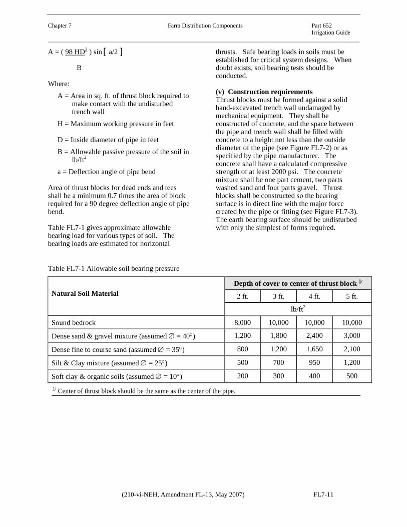
Table FL7-1 gives approximate allowable bearing load for various types of soil. The bearing loads are estimated for horizontal
thrusts. Safe bearing loads in soils must be established for critical system designs. When doubt exists, soil bearing tests should be conducted.
(v) Construction requirements Thrust blocks must be formed against a solid hand-excavated trench wall undamaged by mechanical equipment. They shall be constructed of concrete, and the space between the pipe and trench wall shall be filled with concrete to a height not less than the outside diameter of the pipe (see Figure FL7-2) or as specified by the pipe manufacturer. The concrete shall have a calculated compressive strength of at least 2000 psi. The concrete mixture shall be one part cement, two parts washed sand and four parts gravel. Thrust blocks shall be constructed so the bearing surface is in direct line with the major force created by the pipe or fitting (see Figure FL7-3). The earth bearing surface should be undisturbed with only the simplest of forms required.
Table FL7-1 Allowable soil bearing pressure
Depth of cover to center of thrust block 1/
2 ft. 3 ft. 4 ft. 5 ft. Natural Soil Material
lb/ft2
Sound bedrock 8,000 10,000 10,000 10,000
Dense sand & gravel mixture (assumed ∅ = 40°) 1,200 1,800 2,400 3,000
Dense fine to course sand (assumed ∅ = 35°) 800 1,200 1,650 2,100
Silt & Clay mixture (assumed ∅ = 25°) 500 700 950 1,200
Soft clay & organic soils (assumed ∅ = 10°) 200 300 400 500 1/ Center of thrust block should be the same as the center of the pipe.
(210-vi-NEH, Amendment FL-13, May 2007) FL7-11

Chapter 7 Farm Distribution Components Part 652 Irrigation Guide Figure FL7-2 Cross-section of trench wall
A, Area of Concrete Thrust Block
A
A
Trench Wall
Pipe
SECT. A - A
Center of Thrust
Concrete Thrust Block
D
Thrust
FL7-12 (210-vi-NEH, Amendment FL-13, May 2007)

Chapter 7 Farm Distribution Components Part 652 Irrigation Guide
Figure FL7-3 Location of thrust blocks
Thru line connection, teeThru line connection, cross used as teeChange line size, cross used as reducerChange line size, reducerDirection change, tee used as elbowDirection change, cross used as elbowDirection changeThru line connection, wyeDirection varies, cross usedDirection change, 90 degree elbow usedDirection change, 45 degree elbow usedValveDirection change vertical, bend anchor
1.2.3.4.5.6.7.8.9.
10.11.12.13.
ARROWS INDICATE DIRECTION OF ANTICIPATED THRUSTIf thrusts due to high pressure are expected, anchor valve as shown in . At vertical bends, anchor to resist outward thrusts as shown in .
12
3
65
4
78
9
1211
10
13
1312
(210-vi-NEH, Amendment FL-13, May 2007) FL7-13

Chapter 7 Farm Distribution Components Part 652 Irrigation Guide
FL652.0704 Water measurement
A method of measuring water flow onto a field is an important part of every irrigation system. As the demand for water and energy increases, the need for more efficient use of water increases. Water measurement is essential for equitable distribution of the water supply and for efficient use on the farm. Knowing how much water is applied is essential for proper irrigation water management. Flow measurement has other uses; for example, they can indicate when a pump impeller is becoming worn and inefficient or when well discharge becomes reduced. Flow changes can also indicate clogged screens or partly closed or plugged valves. Consumptive use requirements increasingly specify that measuring devices be installed.
The most common methods of water measurement and the equipment or structures are described in greater detail in NEH, Part 623 (Section 15), Chapter 9, Measurement of Irrigation Water; the ASABE publication Flow Measuring Flumes for Open Channel Systems written by Bos, Replogle, Clemmens in 1991; and the U.S. Bureau of Reclamation’s interagency 1997 publication of the Water Measurement Manual. USDA NRCS and Agricultural Research Service provided input to this publication to make it state-of-art in flow measurement. Publication is late 1997.
Common measuring devices are further described in chapter 9 of this guide. Units of flow rate and flow volume commonly used are cubic feet per second (ft3/sec), gallons per minute (gal/min), gallons per hour (gal/hr), million gallons per day, acre-inches per day, acre-feet per day, miners inches, head of water, acres of water, feet of water, shares, acre feet, acre inches, and inches of water. Head or depth units commonly used are feet, tenths and hundredths of feet; and inches and tenths of inches.
Irrigation consultants must acquaint themselves with terms and flow units used locally and must
be able to convert to units commonly used in tables, graphs, charts, and computer programs.
(a) Planning and design considerations
To accurately measure irrigation water use, water measurement devices must be installed according to requirements specific to that device. In addition, they must be operated under the conditions for which they are designed. Maintenance must be performed as with any other part of an irrigation system. Re-calibration of some devices may be necessary to assure long-term continuing accuracy.
Many types of devices can be used for flow measurement. The best suited device depends on accuracy desired, ease of use, durability, availability, maintenance required, hydraulic characteristics, ease of construction, and installation cost. In some areas state and local requirements dictate. The following methods or devices each have their own flow equation or calibration process.
(i) Open ditch flow Volumetric flow measurements are made by measuring time required to fill a known volume.
Sharp edged orifices of various shapes and sizes can be used as submerged orifices. Head differential of water surface upstream and downstream causes flow through the orifice. Flow is calculated using standard orifice flow equations. The orifice flow “Coefficient” for many types of orifices has been determined experimentally.
Weirs consist of either sharp crested (Cipolletti, 90° V-notch, rectangular) or broad crested (Replogle). Flow depth (head) is measured upstream of crest. Crest width (opening width) can be either standard to fit previously prepared tables or measured. Flow is calculated using standard equations. Sharp crested weirs must meet criteria for the specific type (typically 1/8 inch). Tables are readily available for standard crest widths. Head loss across sharp crested
FL7-14 (210-vi-NEH, Amendment FL-13, May 2007)

Chapter 7 Farm Distribution Components Part 652 Irrigation Guide
weirs is high, often several inches or feet. Where installation and operation meet standard, accuracy can be within 5 percent of actual.
The broad crested weir (sometimes called a Replogle flume) is the easiest to install of any weir or flume and can accurately measure water with as little as 1 inch of head loss. There is only one critical surface and it is level in all directions. However, a short section of lined ditch or flume is required (plus or minus 10 ft). With a stilling well, accuracy can be within 2 percent of actual. Well designed and constructed shaft gauges are typically within 5 percent of actual. Only one flow measurement depth is required.
Flumes consist of Parshall, WSC, cutthroat, or V-notch. Head is measured, crest width is standard or measurable, and flow is calculated using standard equations. Tables are readily available for standard widths. Measurement is fairly accurate at near submerged flow condition; however, measurement of flow depth both upstream and downstream of the control section is required. Accuracy can be within 5 percent of actual. Because of the numerous critical surfaces, these flumes can be difficult to construct. Since flow measuring accuracy is no better (and often worse) these flumes are no longer recommended. The Replogle flume should be used.
When using a current meter, the actual flow velocity at various points and depths within the flow cross-section is measured. Flow is calculated based on . AVQ =
Two methods, the two-point and six-tenths method are typically used to determine mean velocities in a vertical line with a current meter. The two-point method consists of measuring the velocity at 0.2 and then at 0.8 of the depth from the water surface and using the average of the two measurements. High accuracy is obtainable with this method, and its use is recommended. However, the method should not be used where the depth is less than 2 ft.
The six-tenths-depth method consists of measuring the velocity at 0.6 of the depth from
the water surface and is generally used for shallow flows where the two-point method is not applicable. The method gives satisfactory results.
Repeated measurements are typically taken at each measuring location. Technique and practice are important to keep accuracy within 10 percent of actual.
The velocity head rod (jump stick) is used to measure the rise in water surface elevation when a standard rod is placed in the water flow path with the narrow side and then the flat side facing upstream. The difference in water surface level represents velocity head. Velocity (V) is calculated from:
21
)2( ghV =
Flow is then calculated using Q=AV, wherein A is the flow area represented by each velocity and segments are accumulated to present the total flow.
When using the float method, surface flow velocity and flow cross-section are measured, then flow rate is calculated using:
CAVQ =
Where:
C = coefficient of discharge calibrated for site conditions, typically 0.80 to 0.95
When using rated sections, a staff gage is provided to indicate flow depths. Velocity at various depths is measured using a current meter. Flow is calculated using Q = AV. A depth versus flow rate curve is developed for each specific cross section; thereafter, only flow depth is measured. Accuracy depends on technique and consistency of the technician taking readings.
(ii) Pipe flow Flow meters (propeller, impeller) are volumetrically calibrated at the factory for various pipe diameters. Accuracy can be within 5 percent of actual if meter is well maintained and calibrated periodically. Annual maintenance is required. Debris and moss collect quite easily on the point and shaft of the
(210-vi-NEH, Amendment FL-13, May 2007) FL7-15

Chapter 7 Farm Distribution Components Part 652 Irrigation Guide impeller causing malfunction. Therefore, some degree of screening for debris and moss removal may be necessary. Information from flow meters should determine the duration of pumping for many systems. A flow meter is indispensable in order to have efficient and economical irrigation operations. It often reflects water supply problems from wells or other sources and provides data that will indicate repairs and maintenance needs in water supply equipment.
Differential head meters include pitot tube, shunt flow meters, and low head venturi meters. Pressure differential across an obstruction is measured, thus providing velocity head. Flow is calculated using Q = AV. Coefficients provide for improved accuracy.
When using orifice plates, pressure head upstream and downstream of an orifice of known cross section is measured. Flow is calculated using Q = AV. Coefficients provide for improved accuracy.
Ultrasonic meters measure changes in sound transmission across the diameter of the pipe caused by the flowing liquid. They are generally high cost and are most often used only in permanent installations. Some types work well only with turbid water (doppler). Others (transit time) work best in clean water. Portable sonic meters are available, but require a high degree of technology to operate them satisfactorily on different pipe diameters and materials. Frequent calibration can be required.
Pressure gauges are desirable to have in a system so that the operator can operate the system in accordance with the system design. The system efficiency is often dependent upon proper operating pressures.
Information from flow meters should determine the duration of pumping for many systems. A flow meter is indispensable in order to have efficient and economical irrigation operations. It often reflects water supply problems from wells or other sources and provides data that will indicate repairs and maintenance needs in water supply equipment.
FL652.0705 Irrigation runoff, tailwater recovery and reuse
Tailwater recovery and reuse (pumpback) facilities collect irrigation runoff and return it to the same, adjacent, or lower fields for irrigation use. Such facilities can be classified according to the method of handling runoff or tailwater. If the water is returned to a field lying at a higher elevation, it is referred to as a return-flow or pumpback facility. If the water is applied to adjacent or lower-lying field, it is termed sequence use. In all cases runoff is temporarily stored until sufficient volume has accumulated to optimize application efficiency on each succeeding irrigation set.
Components consist of tailwater ditches to collect the runoff, drainage ways, waterways, or pipelines to convey water to a central collection area, a sump or reservoir for water storage, a pump and power unit, and a pipeline or ditch to convey water for redistribution. Under certain conditions where gravity flow can be used, neither a pump nor pipeline is necessary.
(a) Planning and design considerations
(i) Storage A tailwater collection, storage, and return flow facility must provide for temporary storage of a given volume of water. It includes the required pumping equipment and pipeline or ditch to deliver water at the appropriate rate to the application system. A sequence system should have storage, a pump, and only enough pipe to convey water to the head ditch of the next adjacent or downslope field. It may be possible to plan the facility so there is enough elevation difference between fields to apply runoff water to a lower field by gravity without pumping. Only the lowest field(s) requires pumpback or has tailwater runoff.
Recovery facilities may also be classified according to whether or not they accumulate and store runoff water. Facilities storing precipitation and irrigation runoff water are referred to as reservoir systems. Reservoirs can be located either at the lower end of the field or at the upper end. Facilities that return the runoff
FL7-16 (210-vi-NEH, Amendment FL-13, May 2007)

Chapter 7 Farm Distribution Components Part 652 Irrigation Guide
water for direct irrigation require the least storage capacity. They have automatically cycled pumping and are termed cycling-sump facilities.
One or more types of recovery systems may be applicable to a given farm. A sump is used where land value is high, water cannot be retained in a reservoir, or water ponding is
undesirable. Reservoirs are more common and most easily adapted to storage and planned recovery of irrigation tailwater. Hydraulically, only tailwater runoff from one irrigation set needs to be stored. Storing water from a maximum of two irrigation sets improves management flexibility. Figure FL7–4 displays a typical plan for tailwater recovery facility involving a pumpback system.
Figure FL7–4 Typical tailwater collection and reuse facility for quick-cycling pump and reservoir
Cycling-sump facilities require more intensive water management. When cycling begins, the furrow advance phase should begin, otherwise additional furrows must be started. One option is to reduce the incoming water supply by the amount equivalent to the return rate being added.
Reservoir facilities tend to increase irrigation efficiency while decreasing management intensity requirement. Reservoir tailwater reuse facilities collect enough water to use as an independent supply or as a supplement to the
original supply. Thus they have the most flexibility. The reservoir size depends on whether collected water is handled as an independent supply and, if not, on the rate water is pumped for reuse.
Tailwater reuse reservoirs should be at least 8 feet deep, preferably 10 feet deep, to discourage growth of aquatic weeds. For weed control, side slopes of 2 or 2.5 feet horizontal to 1 foot vertical are recommended. Some soils require flatter slopes to maintain stability. A centrally located ramp with a slope of five to one (5:1) or
Head Ditch
Inlet
Sump Pump
Collector Ditch
Return Pipeline
RegulatingReservoir
Water Supply
(210-vi-NEH, Amendment FL-13, May 2007) FL7-17

Chapter 7 Farm Distribution Components Part 652 Irrigation Guide flatter should be provided for wildlife, either as access or for exiting after accidentally falling in. At least 2 feet of water depth should remain in the reservoir to provide pump intake submergence, protect the reservoir bottom seal, and provide water for wildlife. Tailwater inflow must enter the reservoir at or near the pump intake. Most suspended sediments return to the upper end of the field instead of settling in the reservoir.
(ii) Pumps Cycling-sump facilities consist of a sump and pump large enough to handle the expected rate of runoff. The sump is generally a vertical concrete or steel conduit with a concrete bottom. The conduit is about 6 to 10 feet deep when placed on end. Pump operation is controlled automatically by a float-operated or electrode-actuated switch. Some storage can be provided in the collecting ditch or pipeline upstream of the sump.
The size, capacity, location, and selection of equipment for these facilities are functions of the selected irrigation system, topography, layout of the field and the water user’s irrigation management and desires.
Many different low head pumps are used with tailwater reuse facilities. Pumps include single stage turbine, horizontal centrifugal (permanent or tractor driven), submerged vertical centrifugal, and propeller or axial flow pumps. Pumping heads are generally low, consequently energy requirements are low (5 to 10 hp), even for reasonably high flow rates. Tractor driven pumps are typically overpowered.
Caution should be used when selecting pump and power unit size. For example, in a cycling-sump facility the lowest continuous pumping rate that will maintain the design flow rate should be used. For reservoir type facilities where water is delivered from a tailwater sump directly to the head ditch, it is better to pump at a high rate for the first part of an irrigation set (to decrease irrigation advance time). Pumping efficiencies can be in the range of 20 to 75 percent, depending upon the type and size of pump selected, the power unit used, and pump inlet and outlet conditions. Some degree of screening at the pump inlet is generally required. In all cases, irrigation water management should optimize use of water, labor, and energy.
(iii) Sizing for runoff Runoff (RO) flows must be measured or estimated to properly size tailwater reuse sumps, reservoirs, and pumping facilities. Table FL7–2 displays expected recovery in gallons per minute based on irrigation head or inflow and expected runoff. Expected recovery and return to the head of the irrigation system is based on 65 percent of the runoff. Seepage, evaporation, overflow, and miscellaneous losses occur in a recovery, storage, and pumpback system. An irrigation system evaluation should be used to determine runoff. An example of a tailwater recovery and pumpback facility follows:
Furrow flow analysis gives runoff RO = 35% Irrigation head (inflow) Qi = 1,000 gpm Expected recovery at peak runoff Qr = 228 gpm
FL7-18 (210-vi-NEH, Amendment FL-13, May 2007)

Chapter 7 Farm Distribution Components Part 652 Irrigation Guide
Table FL7–2 Expected recovery from runoff 1/
Estimated runoff, Qr (gpm) Inflow
Qi (gpm) 20% 25% 30% 35% 40% 45% 50% 150 20 24 29 34 39 44 49 200 26 33 39 46 52 59 65 300 39 49 59 68 78 88 98 400 52 65 78 91 104 117 130 500 65 81 98 114 130 146 163 600 78 98 117 137 156 175 195 700 91 114 137 159 182 205 228 800 104 130 156 182 208 234 260 900 117 146 176 205 234 263 293
1,000 130 163 195 228 260 293 325 1,200 156 195 234 273 312 351 390 1,400 182 228 273 319 364 410 455 1,600 208 260 312 364 416 468 520 1,800 234 293 351 410 468 527 585 2,000 260 325 390 455 520 585 650 2,200 286 358 429 501 572 644 715 2,400 312 390 468 546 624 702 780 2,600 338 423 508 592 676 671 845 2,800 364 455 546 637 728 819 910 3,000 390 488 585 683 780 878 975
1/ Note: Estimated runoff is that amount of water that normally runs off the end of the furrows or borders. This flow rate can be arrived at by field measurement or from judgment based on soil or field intake characteristics, inflow rates, field slope, length of run, method of irrigation, and irrigator’s ability. Irrigation inflow is the amount of irrigation water (or head) used for the irrigation set.
Use this recovery flow to size conveyance and storage facilities. In addition, capacity should be provided to handle concurrent peak runoff events from both precipitation and tailwater, unexpected interruption of power, and other uncertainties. Where a reservoir or recovery pit is used, it should have the capacity to store the runoff from one complete irrigation set.
Pump capacity will be dependent on the method or schedule of reuse planned. Table FL7–3 provides data for sizing tailwater reservoirs and sumps based on desired pump peak flow and desired set time. Overall irrigation efficiencies obtainable by using tailwater recovery facilities are listed in Table FL7–4.
(210-vi-NEH, Amendment FL-13, May 2007) FL7-19

Chapter 7 Farm Distribution Components Part 652 Irrigation Guide Table FL7–3 Tailwater pit sizing for intermittent pumpback facility 1/
Length of set 6-hour 8-hour 12-hour 24 hour
Pumpback Flow (gpm)
ft3
100 200 267 400 800 200 400 533 800 1,600 300 600 800 1,200 2,400 400 800 1,067 1,600 3,200 500 1,000 1,333 2,000 4,000 600 1,200 1,600 2,400 4,800 700 1,400 1,867 2,800 5,600 800 1,600 2,133 3,200 6,400 900 1,800 2,400 3,600 7,200
1,000 2,000 2,667 4,000 8,000 1,100 2,200 2,933 4,400 8,800
1/ This includes a 10 percent safety factor. Table FL7–4 Overall efficiencies obtainable by using tailwater recovery and reuse facility
First reuse Second reuse Third reuse Fourth reuse Original app. eff.
%
% of water reused
% of orig. water used
Effect use - % of orig
Accum effect
%
% of orig. water used
Effect use - % of orig
Accum effect
%
% of orig. water used
Effect use - % of orig
Accum effect
%
% of orig. water used
Effect use - % of orig
Accum effect
%
40 16 9.6 69.6 2.6 1.5 71.1 1.1 0.7 71.8 0.2 0.1 71.9 60 24 14.4 74.4 5.8 3.5 77.9 1.4 0.8 78.7 0.4 0.2 78.9 60 80 32 19.2 79.2 10.2 6.1 85.3 3.3 2 87.3 1 0.6 87.9 40 20 10 60 4 2 62 0.8 0.4 62.4 0.2 0.1 62.5 60 30 15 65 9 4.5 69.5 2.7 1.4 70.9 0.8 0.4 71.3 50 80 40 20 70 16 8 78 6.4 3.2 81.2 2.6 1.3 82.5 40 24 9.6 49.6 5.8 2.3 52.9 1.4 0.6 53.5 0.3 0.1 53.6 60 36 14.4 54.4 13 5.2 59.6 4.7 1.9 61.5 1.7 0.7 62.2 40 80 48 19.2 59.2 23 9.2 68.4 11 4.4 72.8 5.3 2.1 74.9 40 28 8.4 38.4 7.8 2.4 40.8 2.2 0.7 41.5 0.6 0.2 41.7 60 42 12.6 42.6 17.8 5.3 49.9 7.5 2.3 52.2 3.1 0.9 53.1 30 80 56 16.8 46.8 31.4 9.4 56.2 17.6 5.3 61.5 9.8 3 64.5 40 32 6.4 26.4 10.2 2.1 28.5 3.2 0.7 29.2 1 0.2 29.4 60 48 9.6 29.6 23 4.6 34.2 11 2.2 36.4 5.3 1.1 37.5 20 80 64 12.8 32.8 41 8.2 41 26.2 5.3 46.3 17.5 3.5 49.8
Where irrigation tailwater cannot enter at or near the pump, a small collection basin installed at the inlet to the storage reservoir is more desirable than allowing sediment to collect in the reservoir. The basin can be cleaned easily with available farm machinery, while a large pit requires cleaning with commercial size
equipment. Either way, sediment storage must be provided. Generally when an irrigator sees how much sediment accumulates, erosion reduction measures are taken. They readily relate to costs involved in removal.
FL7-20 (210-vi-NEH, Amendment FL-13, May 2007)

Chapter 7 Farm Distribution Components Part 652 Irrigation Guide
Examples of determining recovery volume and storage capacity for tailwater recovery and reuse systems using Tables FL7–2 and FL7–3 follow:
Given: Inflow = 1,000 gpm @ 12 hour set time Outflow = 40 %
Solution: From Table FL7–2: Recovery = 260 gpm.
This would be the expected flow for a continuously operating pumpback facility.
Given: Inflow = 1,000 gpm @ 12 hour set time
Desired pumpback flow 500 gpm @ 12 hour set
Solution: From Table FL7–3: Volume of storage = 2,000 ft3.
This would be the expected storage needed for an intermittent pumpback facility.
FL652.0706 Irrigation system automation
Automated irrigation systems reduce labor, energy, and water input while maintaining or increasing irrigation efficiency. Automation is the use of mechanical gates, valves, structures, controllers, and other devices to automatically divert water into an operating irrigation system to satisfy the water requirement of a growing crop.
Research and development by ARS, state experiment Stations, and industry have produced structures, controls, computer software, and other devices to automatically control irrigation water. However, automated irrigation (with the exception of microirrigation and solid set sprinkler) use is limited. New technology, including automation, is adopted only when the irrigator views the real (or perceived) risk as being equal to or less than the current procedure being used. Commercially produced systems and components are currently available.
The increasing cost of power for pumping and irrigation labor is increasing irrigator’s interest in ways of reducing costs. Automation of surface and sprinkler systems is one consideration. Many irrigators who consider switching from surface irrigation to sprinkler irrigation have continued with surface methods
to reduce or eliminate pumping costs. All irrigation systems that apply water by surface, sprinkler, subsurface, and micro irrigation methods can presently be automated to some degree. A high potential exists to increase irrigation efficiencies through improved irrigation water management using existing irrigation systems. Reduced labor and increased production are added benefits.
(a) Planning and design considerations for automation
Automated irrigation systems and their associated components are classified as either automatic or semiautomatic.
(i) Automatic systems Fully automated irrigation systems normally operate without operator attention except for calibration, periodic inspections, and routine maintenance. The irrigator determines when or how long to irrigate and then turns water into the system and starts programmed controllers to initiate the automated functions.
Fully automated systems typically use either soil moisture sensors or computer processed climatic data to activate electric or pneumatic controlled switches and valves. Soil moisture sensors send a signal to a central controller when soil water has been depleted to predetermined levels. Daily climatic data can also be used to signal a controller to apply irrigations.
Once irrigation has been started, water is diverted into the farm distribution system and irrigation is completed without operator intervention. Irrigation duration can be controlled by programmed timers, soil moisture sensors, or surface water sensors. Fully automated systems require a water supply available essentially on demand, such as from irrigation district canals, private wells or reservoirs.
(ii) Semiautomatic systems Semiautomatic systems and controls require attention during each irrigation event and are usually simpler and less costly than automatic systems. Most semiautomated systems use mechanical or electronic timers to activate
(210-vi-NEH, Amendment FL-13, May 2007) FL7-21

Chapter 7 Farm Distribution Components Part 652 Irrigation Guide control structures at predetermined times. The irrigator generally determines the beginning time and duration, then manually resets or returns the devices to their original position. Some devices can be moved from one location to another before the next irrigation. Parts of a given system may be automatic, while other parts are semiautomatic or manually operated. Often automation of one irrigation set change (during the night or offsite working hours) has nearly the same benefits as a fully automated system and at considerably less cost and risk.
(iii) Communications Most automated and some semiautomated system components can be remotely controlled by centrally located controllers. Such systems require communication between the controller and system components located in the field. Communication may be by direct interconnecting electrical wires, hydraulic or pneumatic conduits, radio or infrared telemetry, or a combination of these. Spurious signals and interference is sometimes a problem when telemetry is used.
(iv) Surface irrigation system automation Technology is available to automate most surface irrigation systems; however, automation use is limited. New technology adoption by a user must have a real or perceived risk equal to or less than the method or system currently in use. If an irrigator cannot sleep until he or she personally checks to see if a valve or gate changed during the night, automation is of no benefit.
Level basin and level furrow surface irrigation systems are perhaps the easiest to automate. Where irrigation inflows are known, application volume can be controlled by time. With graded furrow and graded border surface irrigation systems, succeeding irrigation set changes can be initiated by the presence of free water on the soil surface at a predetermined location down the field.
Drop-open or drop-close gates in a short flume or lined ditch can be used to control water surface elevation and location in open ditches. Gravity plus the pressure of water in the ditch operates each gate. Typically, irrigation water
discharge from a supply ditch onto a field is controlled by water surface elevation in the ditch and the number of openings onto the field. Ditches must be installed on a predetermined grade and elevation so that water will be applied uniformly to borders or to the correct number of furrows at a proper design rate. Set time is provided to allow a full or planned irrigation to occur.
Simple electronic or windup timers can control gate operation. A 12 volt battery (or 120 volt AC) with a solenoid can move a slide bolt initiating gate movement. Some batteries are kept charged by solar panels. Both drop-open and drop-close gates are actuated and sealed by the energy from water moving in the supply ditch. With drop-open gates, irrigation progresses downstream. Drop-close gates require that irrigation proceed upstream. A 12 volt battery (or 120 volt AC) can be used (either directly or to power a pump) for electric, hydraulic, and pneumatic opening and closing motors and cylinders. Each irrigation head can be semiautomatic with two gate opening (closing) assemblies. While the second assembly is operating, the first or previous assembly is moved ahead and adjusted for the next irrigation set.
Gates, ports, spiles, notches, or longitudinal overflow weirs can direct water onto a field. Adequate erosion control is always a consideration.
Gated pipe systems, including surge and cablegation, can be automated using electric or wind-up timer controlled valves to initiate the irrigation cycle. There after, the surge or cablegation controller operates the irrigation set. Some field cross slope or fall in the gated pipeline is necessary. ARS Publication 21, Cablegation Systems for Irrigation: Description, Design, Installation and Performance (ARS 1985), should be referenced for cablegation design. NRCS publication Surge Flow Irrigation Field Guide (USDA 1986), should be referenced for surge design.
(v) Sprinkler and microirrigation systems Several methods of automating sprinkler and microirrigation systems are available. Center
FL7-22 (210-vi-NEH, Amendment FL-13, May 2007)

Chapter 7 Farm Distribution Components Part 652 Irrigation Guide
pivot manufacturers presently have fully automatic devices including monitoring of climate for determining crop ET, soil moisture monitoring, and system on-off controllers, all controlled with an onboard computer. Automatic systems are available with fully automatic controllers including moisture sensors or time clock operation for solid set sprinkler, micro, and greenhouse irrigation systems.
Periodic move irrigation systems, such as side roll and handmove systems, generally are not automated. However, a simple form of automation is timer controlled lateral shutdown and turn-on. With two laterals the dry lateral can be moved at a time more convenient to the irrigator. This allows the irrigator to have some flexibility when water is changed. Although not necessary, this method works best when water is available on demand.
FL652.0707 Pumping plants
As power and equipment costs increase, designing and maintaining efficient pumping plants becomes more important. Designing an efficient, cost effective pump requires close attention to detail and knowledge of basic hydraulic principles of pump design. The designer must consider the pump, delivery system, and irrigation system as a whole. An annual economic analysis may be needed to determine the least costly alternative. See Chapter 11 of this guide for economic analysis procedures.
Every commercially manufactured pump has a known and published relationship between head (pressure) and volume (capacity) produced. This relationship is generally plotted as a curve called the pump characteristic curve, pump performance curve, or pump head-capacity curve. Multiple curves are used to show characteristics of different impeller diameters and impeller rotation speeds used in the same size and model pump. Pump characteristic curves are available from pump dealers and manufacturers free of charge to designers and pump owners. Every pumping plant evaluation should include a review of the pump
characteristic curves for the pumps being used. Pump specific characteristic curves are essential for designing or evaluating pumps operating in series or parallel.
Variables contributing to the head-capacity relationship include:
• Pump make, model number, and discharge size.
• Impeller type, diameter, and speed of rotation.
• Number of impellers (or pumps) operating in series.
• Net input energy required (usually expressed in brake horsepower).
• Net positive suction head (in feet). • Impeller efficiency.
Net Positive Suction Head (NPSH) is the elevation water can be raised at sea level by the suction side of a specific pump impeller. Unless the pump is self priming, the pump impeller must first be filled with water. If the allowable NPSH for a specific pump is exceeded, the pump will lose prime.
Every pump installation has an optimum operating efficiency. The designer should strive to select pump operation at or near that efficiency. It is very unlikely that a used (or even new) pump at a bargain price can be obtained that fully meets the system needs without first checking the specific Head-Capacity Curve for that specific make, model, and size of pump. Horsepower alone is an inadequate specification for selecting a pump. Flow capacity (Q) and Total Dynamic Head (TDH) are required for pump selection. At high elevations an adjustment factor for elevation may be needed. Manufacturers use different factors to convert brake horsepower to recommended motor or engine horsepower of the drive unit.
Detailed examples of pump design are in NEH, Part 623 (Section 15), Chapter 8, Irrigation Pumping Plants, and NEH, Part 624 (Section 16), Chapter 7, Drainage Pumping. In addition, pump manufacturers’ catalogs and computer programs have information and design assistance on pump design and pump head-capacity characteristics. Chapter 15 of this
(210-vi-NEH, Amendment FL-13, May 2007) FL7-23

Chapter 7 Farm Distribution Components Part 652 Irrigation Guide guide gives information on interpreting pump characteristic curves, and Chapter 11 has information about cost analysis for irrigation systems.
Filters are a necessary component of irrigation systems when the water source is not clean enough to allow for proper operation of the system. Filters are usually needed for microirrigation systems or when pumping from a channel or reservoir.
When water is supplied from a reservoir, ditch or lake, a series of box screens should surround the intake of the water line to prevent debris, plants, and fish from entering the irrigation system. Slotted PVC pipe can often be used as a pump intake screen. The type of filter chosen needs to provide the required capacity and allow for head loss through the filtering process. Pressure gauges installed prior to filtering and following filtering are vital to determine pressure losses and when backwashing is necessary. Refer to manufacturer’s recommendations.
Sand filters are classified in many ways, but generally have the following features: The enclosure houses the filtration media(s) and reservoirs the raw water until it is passed through the filtration media(s); the raw water distributor dispenses raw water over the filtration media; the filtration media is a material used to trap the particulate material in the raw water; the underdrain collects filter water and retains filtration media in the enclosure; and, the clean out port allows for removal of filtration media from the enclosure.
Filtration Operation: Raw water enters the filter through the backwash valve, over the water distributor, through the sand bed, where deposition of particulate material occurs, and the filtered water is collected through the stainless steel underdrain and discharged out the bottom.
Refer to Figure FL7-5 for an illustration of filtration operation.
Backwash Operation: The backwash is initiated by screwing the backwash handle forward. This shuts off the incoming raw water and opens the backwash port to a near atmospheric condition. The pressurized filter water from the adjacent filter(s) is forced through the stainless steel underdrain, upward through the gravel pack, expanding the sand bed and forcing the lighter particulate material out the backwash port and down the backwash line. Screwing the backwash handle in the reverse direction puts the sand filter back into the filtration operation. Refer to Figure FL7-6 for an illustration of backwash operation.
Screen filters have many different configurations but are usually classified as interior flow or exterior flow. In the first case, raw water enters the interior of the screen cartridge and filtered water exits along the housing body as shown in Figure FL7-7. The support structure for the screen material is the inside of some type of cylinder or the cylinder itself is the screen.
Exterior flow screen filters allow raw water to enter along the housing body and through the exterior screen cartridge as shown in Figure FL7-8. Filtered water exits through the interior of the screen and out of the bottom of the housing. The support structure for the screen material is the outside of some type of cylinder or the cylinder itself is the screen.
Screen filters may be cleaned manually by removing the screen element and physically cleaning it, through flushing by using raw water to clean the screen surface as shown in Figure FL7-9, or backwashing by using filtered water and forcing it back through the screen toward the raw water side as shown in Figure FL7-10.
FL7-24 (210-vi-NEH, Amendment FL-13, May 2007)

Chapter 7 Farm Distribution Components Part 652 Irrigation Guide
Figure FL7-5 Filtration operation
Figure FL7-6 Backwash operation
Figure FL7-7 Screen filter with interior flow
(210-vi-NEH, Amendment FL-13, May 2007) FL7-25
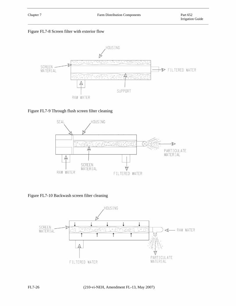
Chapter 7 Farm Distribution Components Part 652 Irrigation Guide Figure FL7-8 Screen filter with exterior flow
Figure FL7-9 Through flush screen filter cleaning
Figure FL7-10 Backwash screen filter cleaning
FL7-26 (210-vi-NEH, Amendment FL-13, May 2007)

Chapter 7 Farm Distribution Components Part 652 Irrigation Guide
FL652.0708 Drainage systems
Purposes of agricultural drainage of irrigated land are to control and manage soil moisture in the crop root zone, provide for improved soil conditions, and improve plant root development. Soil used for growing turf, landscaping, and agricultural crops must have free drainage. In some cases soils are naturally well drained; however, many soils need surface and subsurface drainage systems installed to provide proper soil moisture management flexibility. The greater the management flexibility, the greater the potential for proper water and nutrient management. Thus, to improve water quality, management flexibility must improve. Where water tables are in or near the plant root zone, water table control is an essential component of irrigation water management.
Capacity of drainage improvements must be based on an analysis of the area irrigated, the anticipated irrigation application efficiency, and the proportion of runoff and deep percolation anticipated as runoff.
Subsurface drainage installation on irrigated land is not a substitute for proper irrigation water management. However, adequate drainage of the crop root zone is essential for long-term production. Only when proper irrigation water management is practiced should subsurface drainage installation be considered as an additional water management practice. Also, subsurface drainage is a part of, not a substitute for, proper salinity, sodicity, nutrient, and pesticide management.
Irrigation with saline or sodic water can inhibit crop growth and degrade the soil resource. See chapters 2 and 13 of this guide for information on irrigation water and soil salinity or sodicity. Good water management along with properly designed and managed subsurface drainage systems can help maintain a level of salinity or sodicity in the plant root zone that allows sustained agricultural production.
Provisions to remove excess precipitation and soil seepage water promptly and safely from irrigated land must be maintained as part of farm
irrigation water management. Without proper water removal, soil, water, plant and animal resources can be degraded. In some cases discontinuation of improperly managed irrigation may be the only possible alternative.
Properly installed subsurface drainage systems can be used successfully in water limited areas as a supplemental source of irrigation water, if it is of reasonably good quality. The water may be used on the field that was drained or on other crops in a different field.
Increasing the plant root zone (available soil-water storage) is a recommended water conservation practice. In high saline or sodic areas, subsurface drainage water may be used on salt-tolerant crops that are specifically grown to dispose of drainage water. Special disposal methods, such as use of the effluent for irrigation of agroforestry plots, for constructed wetlands, or in evaporation ponds, may be necessary for poor quality water that cannot be disposed of in public water bodies. Caution must be exercised, however, to know if toxic elements are in the drainage effluent and, if so, the concentration. Because ponded water attracts waterfowl, any negative impacts on wildlife need to be known and avoided.
In high water table soils, subsurface drainage improves soil condition and the potential plant root zone depth for most crops. This increased soil volume increases plant-water availability when precipitation is less than adequate, and improves plant nutrient availability. Improved soil condition increases soil micro-organism activity, thus less fertilizer is generally needed, plus the potential for leaching of nutrients below the plant root zone is decreased.
Laws, regulations, and public perception may increasingly limit new subsurface drainage developments and methods used to dispose of drainage water. Most drainage issues will involve maintaining or rehabilitating existing drainage systems. The irrigation/drainage planning technician must be thoroughly familiar with Federal, state, and local laws and regulations governing drainage.
(210-vi-NEH, Amendment FL-13, May 2007) FL7-27

Chapter 7 Farm Distribution Components Part 652 Irrigation Guide (a) Precipitation runoff
High volume storm water runoff should be safely stored, diverted around, or carried through the irrigation system to protect the land, irrigation system, and crop. This may require special erosion control measures or modifications in the design or layout of an irrigation system.
Standard NRCS procedures, as illustrated in the Florida Supplement to the Engineering Field Handbook, Part 650, Chapter 2, Estimating Runoff, are available to determine the volume and rate of runoff from precipitation. Runoff from precipitation can leave the land through natural watercourses or constructed ditches and channels. Tailwater or wastewater ditches are generally needed at the lower end of irrigation runs to collect runoff from rainfall and irrigation. Storm runoff peaks generally govern capacity requirements. Where storage and tailwater recovery facilities are provided for irrigation, storm runoff containing a large sediment volume should bypass or be trapped before entering the storage reservoir to prevent rapid loss of storage capacity.
(b) Irrigation runoff (tailwater)
Surface irrigation systems cannot place 100 percent of applied water in the plant root zone. However, level basin, border, and furrow surface irrigation systems operated with good water management including planned deficit irrigation in all or part of the field can approach 100 percent water use. Using tailwater reuse on surface irrigation systems along with good water management practices can be efficient. Planned irrigation deficit in all or part of the field, surge, cutback, blocked ends and tailwater reuse are techniques or modifications that, when properly used, can improve irrigation uniformity while reducing field or farm runoff.
To make a near uniform application of water with a graded surface irrigation system without using some of the above techniques or modifications, some irrigation runoff must result, typically 30 to 50 percent. Often runoff water is reduced or eliminated by reducing inflow streams or blocking the ends of furrows and borders. This practice without an
appropriate change in water management and system layout often trades runoff water for deep percolation (non-uniformity), which cannot be seen.
Theoretically, sprinkle irrigation systems should not have runoff. In reality, even with proper water and soil management, local translocation, and perhaps some field runoff can occur because of the variable conditions including soils, topography, and crop interference. If field runoff is anticipated, runoff facilities and management must be a part of every irrigation system plan. Tailwater from irrigation must be recovered and reused, or it must be disposed of without damage to downstream lands and water supplies.
(c) Subsurface drainage
Excess percolation of precipitation and irrigation water and nearly impermeable soil layers can cause high water tables. High water tables can restrict crop root development and promote saline or sodic soil conditions. Seepage from upslope areas, canals, reservoirs, and sumps may also waterlog adjacent downslope lands. Excess water that enters the soil profile often percolates below the crop root zone. Unless the underlying material is sufficiently permeable to allow continued flow, a water table can form and encroach into the potential plant root zone. The water table must be held below the crop root zone to provide aerobic soil conditions for plant root development and function.
Subsurface drains are normally designed to control the water table at least 4 feet below the ground surface. Significant quantities of water can be provided from a water table for plant use. Desirable depth to water table is somewhat dependent on soil type. See information on upflux rate in Chapter 6, Subirrigation. Subsurface drainage systems may consist of interceptor drains, relief drains, or pumped drains. Subsurface drains may also be needed to reduce or eliminate toxic materials from moving to deeper aquifers that contain high quality water.
Design of subsurface drains should be according to procedures for arid land as described in NEH,
FL7-28 (210-vi-NEH, Amendment FL-13, May 2007)

Chapter 7 Farm Distribution Components Part 652 Irrigation Guide
Part 624 (Section 16), Drainage of Agricultural Lands, Chapters 4 and 5.
(i) Interceptor drains Interceptor drains are used in sloping areas that have a high water table gradient. They are generally oriented perpendicular to the direction of ground water flow. Subsurface drains are commonly used because the drain must be located according to soil and ground water conditions, which may not correspond to field boundaries, fences, or property lines.
(ii) Relief drains Relief drains are generally used in level to gently sloping areas that have a low water table gradient (slow water movement through the soil). These drains generally are planned as a series of parallel drain conduits in a grid or herringbone pattern in which each lateral is connected to a submain or main that leads to an open channel or sump pump.
(iii) Pumped drains Pumped drains are used when soils are underlain by porous sand or gravel with aquifers that can be lowered by pumping or where insufficient fall exists for a gravity outlet. Detailed subsurface and ground water studies are required to determine the feasibility of lowering the water table by pumping, on a large enough area to be economical.
Pumped drains are also used where a layering of the groundwater table is for a short period of time, i.e., during harvest for improved soil trafficability, in the early part of the growing season for plant establishment, and following periods of excess precipitation.
(d) Environmental factors
Drainage planning requires careful consideration of environmental factors including wetlands, wildlife habitat, and water quality. An environmental assessment of impacts on soil, water, air, plant, and animal resources is important when dealing with drainage. Drainage related environmental issues and laws are complex and subject to varying interpretation, which complicates planning. It frequently takes
considerable effort to resolve or to even determine the status of these issues.
(i) Wetlands A certified wetland determination is necessary where drainage is planned and wetland conditions are suspected or evident. Wetlands created by irrigation water seepage or runoff may be subject to Federal, state, or local laws; although they are exempted as artificial wetlands under the Food Security Act.
Surface and subsurface drainage water can sometimes be used to create or enhance wetland areas. Quality of drainage discharges is an important consideration for the creation or enhancement of wetlands used by wildlife.
(ii) Water quality National and State laws require that drains discharging into State watercourses meet certain water quality standards. Currently irrigation runoff is classified as a nonpoint source. As such, discharge permits are not required. However, if a downstream water user files a complaint, water quality restrictions may be placed on discharges from irrigated land. Permits are required for discharges from point sources, such as feedlots, and can be required for subsurface drain outlets.
FL652.0709 Chemigation
Chemigation is the application of chemicals via an irrigation application system. Included are fertilizers, soil amendments (gypsum or sulfur), herbicides, insecticides, fungicides, nematicides. Specific forms of chemigation are sometimes called fertigation, herbigation, or insectigation; however the most commonly used term that covers everything is chemigation.
Chemigation is accomplished by injecting the chemical into a flowing water supply. Most chemigation is applied by sprinkler systems (linear or center pivots) or microirrigation systems. Soil amendments are typically applied in surface systems. Unless uniformity is high, applying agricultural chemicals through irrigation systems is not recommended. Always
(210-vi-NEH, Amendment FL-13, May 2007) FL7-29

Chapter 7 Farm Distribution Components Part 652 Irrigation Guide follow instructions on the chemical label to determine suitability and methodology of chemigation.
Properly managed chemigation requires injecting chemicals into the water in carefully measured amounts. Care must be taken to prevent backflow of chemically laden water into any water source. Backflow prevention devices are required where chemicals are injected into any pressurized irrigation system. Distribution of water on the field must be uniform, carefully managed, and controlled. This requires the proper equipment and careful attention to detail. Only chemicals labeled for chemigation (usually sprinkler system) application should be used.
Water quality laws are strict concerning handling of chemicals applied through irrigation systems. In Florida, the irrigation system must comply with Florida Statute – 487.064, Anti-siphon requirements for irrigation systems.
(a) Advantages
The advantages of using chemigation include:
• Cost of chemigation versus aerial or ground application can be less.
• A chemical can be applied when it is needed without waiting for the proper weather conditions, the supplier or labor availability. The procedure can reduce total labor.
• Application can be more uniform than by other methods under certain conditions.
• With soil incorporated herbicides, the appropriate amount of water can be applied to incorporate the herbicide to the depth desired and to activate it immediately.
• Soil compaction is reduced because it is not necessary to pass field equipment over the field to apply chemicals.
• Mechanical damage to crops is less than with mechanical surface application methods.
• The hazards to operators are fewer. • Less fertilizer may be required, particularly
under micro irrigation. • Losses from wind drift can be reduced or
eliminated depending on the method of irrigation. This can reduce one cause of chemical loss and pollution.
• Chemigation techniques are compatible with no-till soil management systems.
(b) Disadvantages
The disadvantages of using chemigation are:
• Some chemicals are corrosive to irrigation equipment, especially immediately downstream of the injection point. In most cases the chemicals are diluted further downstream to the point that corrosion is not a serious problem. Injection equipment must be designed to handle concentrated chemicals.
• Combining chemicals can be dangerous and expensive if not done with full knowledge of the potential, sometimes violent, reactions. Chemicals can also produce precipitates, which can clog equipment, or produce toxic vapors.
• Losses because of volatilization can occur, particularly under sprinkler irrigation.
• Chemicals that can be used successfully under chemigation are limited. Many chemicals are either not registered for chemigation application or are specifically prohibited from being used.
• Excess water application or rainfall during chemigation can cause the loss of chemicals or make them ineffective through deep percolation or runoff. Lost chemicals can contribute to water pollution.
• Special injection equipment and irrigation system safety equipment are required. This adds to the expense of the operation.
• A potential hazard to water supplies is always present particularly with pesticides and herbicides.
• Much is still not known about the best and safest ways to handle chemigation. The technique is relatively new.
• A high degree of management and irrigation uniformity are required.
(c) Planning and design considerations
The following information is intended to give NRCS personnel a general understanding of chemigation on pressure type systems. Detailed design of such systems must be done by a qualified irrigation designer that understands the
FL7-30 (210-vi-NEH, Amendment FL-13, May 2007)

Chapter 7 Farm Distribution Components Part 652 Irrigation Guide
state and local laws, rules and regulations regarding anti-siphon requirements for irrigation systems used to apply chemicals and fertilizers. The irrigation designer shall state on the engineering plans that the anti-siphon design meets all state and local laws, rules, and regulations. The operation and maintenance requirements of the anti-siphon system must be included with the irrigation system design.
(i) Chemical injection equipment Chemical compounds to be applied through injection equipment must be in one of the following forms:
• Miscible or emulsible liquid • Soluble, dry powder (crystal) • Insoluble, wettable, dispersible powder.
Some equipment is manufactured for specific material (i.e., type of chemical, chemical concentration, viscosity), so the appropriate types of chemicals and equipment should be chosen. The equipment must have adequate capacity. The common methods of injecting chemicals are illustrated in figures FL7–11 to FL7–15. Pumps can be powered by electric drives, engine drives, or water motors. Equipment can be categorized by the way the inflow rate of the chemical is controlled. The
four categories are gravity flow, educator, metering pump, and proportioner system.
A chemical injector injects a metered amount of liquid chemical (fertilizer, herbicides, pesticides, etc.) into the irrigation system. Pressure differential, venturi vacuum, and metering pumps are used in the injection of fertilizers and chemicals into irrigation systems. Injectors should be installed in the system ahead of the filter so that any insoluble chemicals will be filtered out before entering the lines. An injector pump will not contribute any system pressure losses if it pumps chemicals from a tank into the system. However, when considering an injector, it is necessary to size it so it will inject at a higher pressure than the main pump.
Gravity flow from chemical storage tanks (Figure FL7–11) is the crudest category of chemical injection. Control of injection rate is accomplished by adjusting a valve that approximately regulates chemical flow into the irrigation water. Chemical flow is either into the suction end of a pump or into an open gravity flow system. This type injection is generally used in surface systems, particularly to add soil additives, such as sulfur compounds. It requires careful operator attention.
Figure FL7–11 Gravity flow from storage tank
(210-vi-NEH, Amendment FL-13, May 2007) FL7-31

Chapter 7 Farm Distribution Components Part 652 Irrigation Guide
Using an educator is the simplest way of introducing chemicals into the system. Methods used for this category are:
• Injection on suction side of pump (Figure FL7–12)
• Venturi principle injection (Figure FL7–13) • Pitot tube injection (Figure FL7–14)
The chemical injection rate is approximately proportional to water flow. The method requires some operating attention. It can handle liquids and water soluble or dry material. The educator equipment should be used where water flow is nearly constant.
Figure FL7–12 Injection on suction side of pump 1/
1/ Note: Check local regulations before using this method of chemical injection.
FL7-32 (210-vi-NEH, Amendment FL-13, May 2007)

Chapter 7 Farm Distribution Components Part 652 Irrigation Guide
Figure FL7–13 Venturi principle of injection
Figure FL7–14 Pitot tube injection
(210-vi-NEH, Amendment FL-13, May 2007) FL7-33

Chapter 7 Farm Distribution Components Part 652 Irrigation Guide Using a metering pump (Figure FL7–15) accurately meters the chemical into the irrigation water at a predetermined rate. The chemical inflow rate is constant with respect to time and allows the operator to make changes in the
application rate. It should be used where the rate of water flow is nearly constant. The method of injection used is the injection pump. It can only inject liquids.
Figure FL7–15 Pressure metering pump injection
The proportioner system is the method of injection which accurately proportions chemicals to irrigation water flow. It consists of a sensor that determines the water flow rate, a chemical flow control module, and an injector pump that injects the chemical. This category of injection equipment should be used where the irrigation flow rate varies. It is automatic and requires little operator attention.
(ii) Safety equipment If the injection system is not carefully designed and safely managed, there is a possibility of contaminating the water supply when chemicals are injected into irrigation systems. In Florida, the irrigation supply is also the drinking water supply for most of the State’s inhabitants. The Florida irrigator has the responsibility of protecting water quality. Water contaminated by chemicals could affect the health of other users of the water supply. If not properly utilized,
chemigation exposes an irrigator to possible liability. Safety equipment exists which will protect both the water supply and the chemical purity in the storage tank. The possible dangers in chemigation include backflow of chemicals into the water source and water backflow into the chemical storage tank. Backflow to the water source will cause contamination. Backflow to the storage tank can rupture the tank or cause overflow, contaminating the area around the tank, and perhaps indirectly contaminating the water source. Once these potential problems are addressed and solved, the risk of liability in chemigation is no greater than the liability that arises from the field use of agricultural chemicals utilizing other modes of application. For technical reasons such as reduced wind drift, rapid movement into the soil, and high dilution rates, chemigation could result in less liability risk than traditional methods of
FL7-34 (210-vi-NEH, Amendment FL-13, May 2007)

Chapter 7 Farm Distribution Components Part 652 Irrigation Guide
chemical application if proper backflow preventers are used.
Technology is available to make the safety aspects of chemigation acceptable. However, any time mechanical devices are being used there is always the possibility of failure, malfunction, or accidents. Successful and safe chemigation requires safety devices be installed on the chemigation system. These devices are designed to eliminate three possible pollution problems:
• Backflow of undiluted chemicals to the nurse tanks or water source
• Spill of chemicals on the surface • Backflow of water mixed with chemicals
from the irrigation system.
American Society of Agricultural Engineering Standard ASABE EP409 covers safety standards for chemigation equipment and operation. The rules governing the installation of backflow prevention devices are found in Section 487.055 of the Florida Statute. The rules relating to backflow protection were designed to protect the surface and groundwater resources of the state. The Environmental Protection Agency provides stringent requirements for safety equipment and procedures when applying certain agricultural chemicals through pressurized irrigation systems. Chemicals approved for chemigation have specific verbatim statements on the label. They include:
• The system must contain a functional check valve, vacuum relief valve, and low pressure drain appropriately located on the irrigation pipeline to prevent water source contamination.
• The pesticide injection pipeline must contain a functional, automatic, quick-closing check valve to prevent flow of fluid back toward the injection pump.
• The pesticide injection pipeline must also contain a functional, normally closed, solenoid- operated valve located on the intake side of the injection pump and connected to the system interlock to prevent fluid from being withdrawn from the supply
tank when the irrigation system is either automatically or manually shut down.
• The system must contain functional interlocking controls to automatically shut off the pesticide injection pump when the water pump motor/engine stops.
• The irrigation line or water pump must include a functional pressure switch which will stop the water pump motor when the water pressure decreases to the point where pesticide distribution is adversely affected.
• Systems must use a metering pump, such as a positive displacement injection pump (i.e., a diaphragm pump) effectively designed and constructed of materials that are compatible with pesticides and capable of being fitted with a system interlock.
• Do not apply pesticides when wind speed favors drift beyond the area intended for treatment.
Safety devices are described in the following paragraphs.
The interlock connects the irrigation pumping plant and the chemical injection pump. If the irrigation pump stops (line pressure drops), the injection pump stops.
An automatic low pressure drain should be placed on the bottom of the irrigation pipeline. If the mainline check valve leaks, the solution will drain away from, rather than flow into the water source.
Backflow prevention valve is used to keep water or a mixture of water and chemicals from draining or siphoning back into the water source.
The single anti-siphon device assembly required for backflow prevention when non-toxic chemicals are injected is illustrated in Figure FL7–16. The double anti-siphon device assembly required for backflow prevention when toxic chemicals are injected is illustrated in Figure FL7-17. Toxic chemicals are defined as those whose labels bear the signal words “Danger” or “Poison”.
(210-vi-NEH, Amendment FL-13, May 2007) FL7-35

Chapter 7 Farm Distribution Components Part 652 Irrigation Guide Figure FL7–16 Single anti-siphon device assembly
Figure FL7-17 Double anti-siphon device assembly
FL7-36 (210-vi-NEH, Amendment FL-13, May 2007)

Chapter 7 Farm Distribution Components Part 652 Irrigation Guide
Inspection port - Located between the pump discharge and the mainline check valve, the port allows for a visual inspection to determine if the check valve leaks. The vacuum relief valve connection can serve as an inspection port.
Chemical injection line check valve - This device stops flow of water from the irrigation system into the chemical supply tank and, if the
opening pressure is large enough, can prevent gravity flow from the chemical supply tank into the irrigation pipeline following an unexpected shutdown.
Safety features recommended for internal combustion and electric irrigation pumping plants are shown in Figures FL7-18 and FL7-19.
Figure FL7–18 Safety devices for injection of chemicals into pressurized irrigation systems using electric
power
(210-vi-NEH, Amendment FL-13, May 2007) FL7-37

Chapter 7 Farm Distribution Components Part 652 Irrigation Guide Figure FL7–19 Safety devices for injection of chemicals into pressurized irrigation systems using internal
combustion engine power
Chemical suction line strainer is the strainer necessary to prevent clogging or fouling of the injection pump, check valve, or other equipment.
Additional protection can be provided by installation of a normally closed solenoid valve so that it is electrically interlocked with the engine or motor driving the injection pump. The valve provides a positive shutoff on the chemical injection line. If any portion of the downstream irrigation system is lower than the chemical tank, the solenoid valve can prevent the chemical from being siphoned out of the tank.
Chemical resistant hose clamps and fittings are all components that are in contact with the chemical or chemical mixture, from the strainer to the point of injection on the irrigation pipeline, should be made of chemically resistant materials.
Check valves are used in a pipeline to allow flow in one direction only.
(iii) Fertilizer application The great variety of fertilizer products available allow several choices to be considered in selecting a fertilizer for a particular situation. The three categories of fertilizers used are clear liquid, dry, and suspension liquid.
Clear liquid fertilizers are flowable products containing nutrients in solution. This makes them convenient to handle with pump injectors, venturi-tubes, and gravity flow from gravity storage tanks. Liquid fertilizers contain a single nutrient or combinations of nitrogen (N), phosphate (P), and potash (K). The most common liquid fertilizers used are listed in Table FL7–5.
FL7-38 (210-vi-NEH, Amendment FL-13, May 2007)

Chapter 7 Farm Distribution Components Part 652 Irrigation Guide
Table FL7–5 Liquid fertilizers (solutions) for sprinkler application 1/
Approximate pounds of
product for 1 pound of nutrient
Solution product Total Nitrogen
% N
Available phosphoric
acid % P
Water solublepotash % K
Total sulfur % S
N P K S Ammonium nitrate 20 5 Ammonium phosphate
8 24 12 4
Potassium ammonium phosphate
15 15 10 7 7 10
10 10 10 10 10 10 (N-P-K liquid mixes) 15 8 4 7 12.5 25 Urea (low biuret) 23 4.4 Urea - ammonium nitrate
32 3.1
Phosphoric acid 52-54 1.8-1.9 Calcium ammonium nitrate
17 6
1/ Source: National Fertilizer Development Center, Tennessee Valley Authority, Muscle Shoals, Alabama, 1965.
A wide variety of soluble dry fertilizers are used for injection into irrigation systems. The dry fertilizer may be dissolved by mixing with water in a separate open tank and then injected into the irrigation stream, or they can be placed in a pressurized container through which is bypassed
a portion of the sprinkler stream. In the later case the bypassed stream continuously dissolves the solid fertilizer until it has been applied. Typical dry fertilizers are shown in Table FL7–6.
(210-vi-NEH, Amendment FL-13, May 2007) FL7-39

Chapter 7 Farm Distribution Components Part 652 Irrigation Guide Table FL7–6 Dry fertilizers for sprinkler application 1/
Approximate pounds of
product for 1 pound of nutrient
Dry product Total Nitrogen
% N
Available phosphoric
acid % P2O4
Water soluble potash % K2O
Total sulfur % S
N P2O4 K2O S Ammonium nitrate
33.5 3
Calcium ammonium nitrate
26 4
(Mono) ammonium phosphate
11 48 2.6 9 2 40
Ammonium phosphate sulfate
13 39 7 8 2.5 14
Ammonium phosphate sulfate
16 20 15.4 6 5 7
Ammonium phosphate nitrate
24 20 4 5
Ammonium phosphate nitrate
27 14 4 7
Diammonium phosphate
21 53 5 2
Ammonium chloride
25 4
Ammonium sulfate
20-21 24 5 4
Calcium nitrate 15.5 6 Sodium nitrate 16 6 Potassium nitrate 13 44 8 2.3 Urea 45-46 2.2 Double or treble super phosphate
42-46 10 2.3 10
Potassium chloride
60-62 1.7
Potassium sulfate 50-53 18 2 5.5 Sulfate potash magnesia
26 15 4 7
Nitrate soda potash
15 14 7 7
1/ Source: National Fertilizer Development Center, Tennessee Valley Authority, Muscle Shoals, Alabama, 1965.
FL7-40 (210-vi-NEH, Amendment FL-13, May 2007)

Chapter 7 Farm Distribution Components Part 652 Irrigation Guide
Suspension liquid fertilizers produce higher analysis grades than clear grades given the same ratio of N, P, and K. Table FL7–7 shows a comparison of typical analysis of clear and suspension liquid fertilizers. The suspension mixtures contain 110 to 133 percent more plant nutrients than corresponding clear liquids. Because of their higher nutrient content, suspensions generally are manufactured, handled, and applied at less cost than clear liquids. Another advantage is that they can hold large quantities of micronutrients. Table FL7–7 Comparison of typical analysis of
clear suspension-type liquid fertilizers 1/
Ratio N-P-K
Grade clear
Suspension
3:1:0 24-8-0 27-9-0 2:1:0 22-11-0 26-13-0 1:1:0 19-19-0 21-21-0 1:2:2 8-8-8 15-15-15 1:3:1 5-10-10 10-20-20 1:3:2 5-15-10 9-27-18 1:3:3 3-9-9 7-21-21
1/ Source: National Fertilizer Development Center, Tennessee Valley Authority, Muscle Shoals, Alabama, 1965.
A few herbicides are applied by sprinkler systems. Most treatments involve combinations of herbicides in suspension. Only herbicides registered for application with irrigation water can be used. Most application is done with soil applied herbicides before crop germination. Applying irrigation water at low enough rates to use foliage type herbicides is difficult.
Application of pesticides by sprinkler systems is limited. Only pesticides for grasshoppers and corn borers are registered for application by irrigation. Water application must be less than 0.5 inch per hour.
When irrigators apply chemicals through an irrigation system, consideration needs to be given to travel time to the field area being irrigated. The time it takes for a chemical to travel from the point of injection (usually at the pump) to the area being irrigated must be known to calculate when to close the valve or shut down the pump, thus being assured that all the chemical is applied. Volume of clean water following chemical application can be reduced.
(210-vi-NEH, Amendment FL-13, May 2007) FL7-41