chapter 7 - farm distribution component
TRANSCRIPT
NATIONAL ENGINEERING HANDBOOK - PART 652 - IRRIGATION GUIDE
CHAPTER 7 - FARM DISTRIBUTION COMPONENT
(210-vi-NEH, Part 652, Amend. AL1, April 2010) AL7-29(i)
STATE SUPPLEMENTS INDEX PAGE 652.0707 - State Supplement .......................................................................................................... AL7-29(i) General ............................................................................................................................................. AL7-29(1) Pumping Plant .................................................................................................................................. AL7-29(1) Pumps ........................................................................................................................................ AL7-29(1) Centrifugal Pumps ............................................................................................................... AL7-29(1) Turbine Pumps .................................................................................................................... AL7-29(1) Propeller Pumps .................................................................................................................. AL7-29(2) Axial Flow Pumps ................................................................................................................ AL7-29(2) Mixed Flow Pumps .............................................................................................................. AL7-29(2) Pump Characteristic Curves ...................................................................................................... AL7-29(2) Total Dynamic Head v. Discharge ....................................................................................... AL7-29(2) Efficiency v. Discharge ........................................................................................................ AL7-29(3) Input Power v. Discharge .................................................................................................... AL7-29(3) Net Positive Suction Head v. Discharge ............................................................................. AL7-29(3) Power Units ................................................................................................................................ AL7-29(3) Pumping Plant Head .................................................................................................................. AL7-29(4) Distribution Pipelines ........................................................................................................................ AL7-29(5) Selection .................................................................................................................................... AL7-29(5) Design Considerations ............................................................................................................... AL7-29(5) Water Hammer .................................................................................................................... AL7-29(5) Safety Devices .................................................................................................................... AL7-29(5) Manual Valves .............................................................................................................. AL7-29(5) Check Valves ................................................................................................................ AL7-29(5) Pressure Reducing Valve ............................................................................................. AL7-29(5) Anti-Syphon or Backflow Prevention Units ................................................................... AL7-29(6) Drain Valves .................................................................................................................. AL7-29(6) Pressure Regulating Valves ......................................................................................... AL7-29(6) Pressure Release Valves ............................................................................................. AL7-29(6) Air Release Valves ....................................................................................................... AL7-29(6) Air and Vacuum Valves ................................................................................................ AL7-29(6) Combination Air Valves ................................................................................................ AL7-29(6) Thrust Blocks ................................................................................................................ AL7-29(7) Accessories ...................................................................................................................................... AL7-29(7) Booster Pumps .......................................................................................................................... AL7-29(7) Pressure Tanks .......................................................................................................................... AL7-29(7) Pressure Gauges ....................................................................................................................... AL7-29(7) Flow Meters ............................................................................................................................... AL7-29(8) Chemical Injectors ..................................................................................................................... AL7-29(8) Chlorine Injection ....................................................................................................................... AL7-29(9) Filters ........................................................................................................................................ AL7-29(9) Automation ....................................................................................................................................... AL7-29(9) Automatic Valves and Controllers .................................................................................................... AL7-29(9) Automatic System with a Master Valve ..................................................................................... AL7-29(10)

NATIONAL ENGINEERING HANDBOOK - PART 652 - IRRIGATION GUIDE Chapter 7 – Farm Distribution Components
(210-vi-NEH, Part 652, Amend. AL1, April 2010) AL7-29(ii)
STATE SUPPLEMENTS INDEX (con’t)
TABLES
Table AL7-1. Advantages and Disadvantages of Commonly Used Irrigation Pumps. .................... AL7-29(11) Table AL7-2. Advantages and Disadvantages of Various Power Units. ......................................... AL7-29(12)
FIGURES
Figure AL7-1. Horizontal Centrifugal Pump for Surface or Pit Installation. ................................... AL7-29(13) Figure AL7-2. Deep-Well Turbine Pump. ...................................................................................... AL7-29(14) Figure AL7-3. Submersible Pump. ................................................................................................ AL7-29(15) Figure AL7-4. Propeller Pumps. .................................................................................................... AL7-29(16) Figure AL7-5. Typical Pump Performance Curve. ........................................................................ AL7-29(17) Figure AL7-6 Illustration of Valve Location. ................................................................................. AL7-29(17) Figure AL7-7. Typical System Using a Deep-Well Pump with a Pneumatic Pressure Tank. ....... AL7-29(18) Figure AL7-8. Chemigation Safety Equipment for Internal Combustion Engine Irrigation ............ AL7-29(18) Pumping Plant. Figure AL7-9. Chemigation Safety Equipment for Electric Motor Irrigation Pumping Plant. ........... AL7-29(19) Figure AL7-10. Automatic System with a Master Valve.

NATIONAL ENGINEERING HANDBOOK - PART 652 - IRRIGATION GUIDE Chapter 7 – Farm Distribution Components
(210-vi-NEH, Part 652, Amend. AL1, April 2010) AL7-29(1)
652.0707 - State Supplement GENERAL In order for an irrigation system to operate as designed and function effectively, consideration of many irrigation components is necessary. This supplement will identify and briefly discuss the important components. PUMPING PLANT
The pumping plant selected must be capable of delivering the required capacity at the designed operating pressure and with optimum efficiency. It is often necessary to contact manufacturer’s representatives to ensure that the pumping plant selected can perform as required. A pump will operate most satisfactorily when the actual field conditions approximate the conditions predicted during design. The operating or field conditions should, therefore, be determined as accurately as possible. If there is a variation in operating head, both the maximum and minimum variation should be determined and furnished to the manufacturer to permit selection of the most satisfactory pump. With the use of accurate data, the system planner can select the most suitable pump and associated equipment and; thereby, ensure satisfactory performance of the system. Pumps Centrifugal, turbine, and propeller pumps are commonly used for irrigation. Each type of pump is adapted to a certain set of conditions under which it will give efficient service. Centrifugal Pumps. Centrifugal pumps are built in two types; the horizontal centrifugal and the vertical centrifugal. The horizontal type has a vertical impeller connected to a horizontal shaft. The vertical centrifugal pump has a horizontal impeller connected to a vertical shaft. Both types of centrifugal pumps draw water into their impellers, so they must be set relatively close to the water surface. In this respect, the vertical type has an advantage in that it can be lowered to the depth required to pump water and the vertical shaft extended to the surface where power is applied. The centrifugal pump is limited to pumping from reservoirs, lakes, streams, and shallow wells where the total suction lift is less than 20 feet. The horizontal centrifugal pump (See Figure AL7-1), is the most commonly used in irrigation. It costs less, is easier to install, and is more accessible for
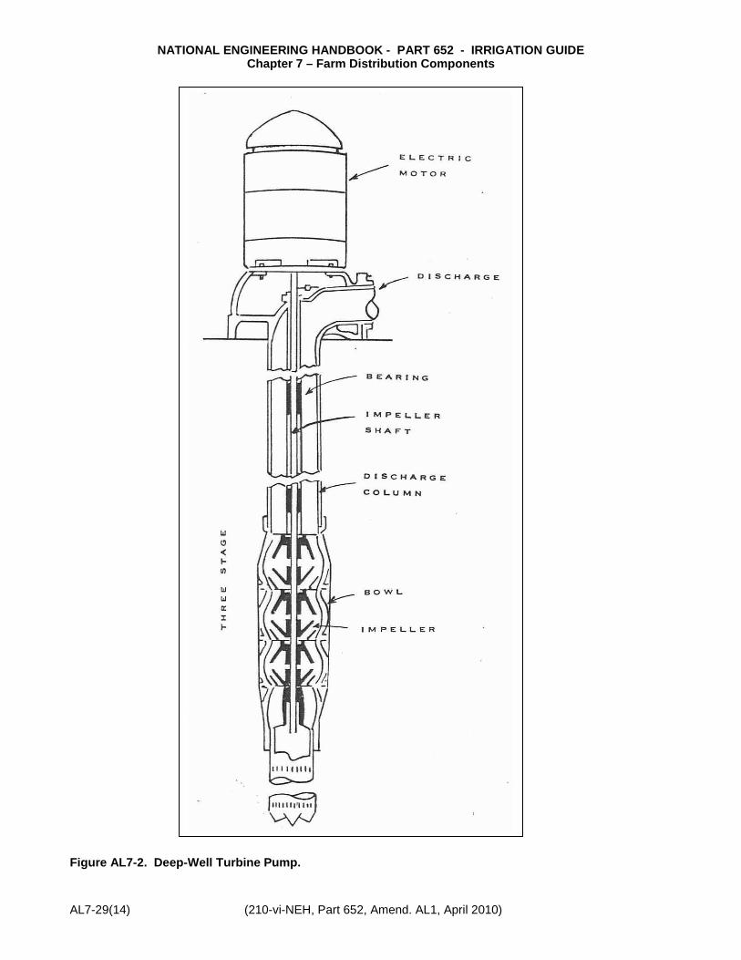
inspection and maintenance; however, it requires more space than the vertical type. The vertical centrifugal pump may be submerged or exposed. The exposed pump is set in a watertight sump at an elevation that will accommodate the suction lift. The submerged pump is set so the impeller and suction entrance are under water at all times; thus, it does not require priming. However, because the pump is not easily accessible, the shaft bearings do not usually get proper attention, causing high maintenance costs. Pumps of this kind usually are restricted to pumping heads of about 50 feet. Turbine Pumps. The deep-well turbine pump is adapted for use in cased wells, or where the water surface is below the practical limits of a centrifugal pump. To insure the proper selection of a turbine pump the following must be known: 1. Depth of well 2. Inside diameter or casing 3. Depth of static water level 4. Drawdown/yield relationship curve 5. Depth-to-screen section 6. Pump capacity requirements All this is essential in selecting a pump that will fit inside the well, deliver the required amount of water at the desired pressure, and assure that the bowls are submerged during operation. Turbine pumps are equipped with impellers that fit inside a series of bowl-shaped cases. Each case is known as a stage. Stages are added to develop additional head. The number of stages needed for a pump installation are determined by the amount of water required and the pressure at which it is to be delivered. Turbine pumps may be either oil lubricated or water lubricated. If there is any fine sand being pumped, the oil lubricated pump should be used because it will keep the sand out of the bearings. If the water is for domestic use, it must be free of oil; consequently, the water lubricated pump should be used. Turbine pumps are available with either semi-open or enclosed impellers. The semi-open impeller will tolerate more sand than the enclosed impeller, and it can be adjusted. The enclosed impeller is supposed to retain high efficiency without adjustment. (Figure AL7-2) shows a typical deep-well turbine pump.)

NATIONAL ENGINEERING HANDBOOK - PART 652 - IRRIGATION GUIDE Chapter 7 – Farm Distribution Components
AL7-29(2) (210-vi-NEH, Part 652, Amend. AL1, April 2010)
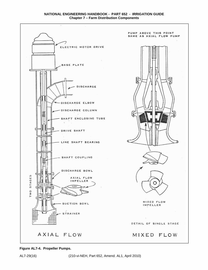
The submersible pump is simply a turbine pump that is close-coupled to a submersible electric motor attached to the lower side of the turbine. Both pump and motor are suspended in the water; thereby, eliminating the long-line shaft and bearing retainers that are normally required for a conventional deep-well turbine pump. Operating characteristics are the same as for deep-well turbine pumps. (Figure AL7-3 shows a typical submersible pump.) Propeller Pumps. Propeller pumps are chiefly used for low-lift, high discharge conditions. There are two types of propeller pumps; the axial flow or screw type, and the mixed flow. The major difference between the axial flow and the mixed flow propeller pumps is the type of impeller (See Figure AL7-4). The principal parts of a propeller pump are similar to the deep-well turbine pump and include a head, an impeller, and a discharge column. A shaft extends from the head down the center of the column to drive the impeller. Some manufacturers design their pumps for multi-stage operation by adding additional impellers where requirements demand higher heads than obtainable with single stage pumps. Where propeller pumps are adapted, they have the advantage of low, first-cost and the capacity to deliver more water than the centrifugal pump, for a given size impeller. Also, for a given change in pumping lift, the propeller pump will provide a more nearly constant flow than a centrifugal pump. Their disadvantage is that they are limited to low head operations. Axial Flow Pumps. The axial flow single stage propeller pumps are limited to pumping against heads of about 10 feet. By adding additional stages, heads of 30 to 40 feet are obtainable. These pumps are available in sizes ranging from 8 to 48 inches. Mixed Flow Pumps. The mixed flow propeller pump is designed especially for large capacities with moderate heads. The smaller single-stage pumps will operate efficiently at low heads of 6 to 26 feet. The multiple stage and large size pumps will handle heads up to approximately 125 feet. They are generally built in sizes ranging from 10 to 30 inches. The mixed flow pump uses an open-vane, curved-blade impeller which combines the screw and centrifugal principles in building up the pressure head. They have a capacity range of from 1,000 gpm to approximately 50,000 gpm, depending on size, stages, and heads. The mixed flow pump operates more efficiently against higher heads than
the axial flow propeller pump. (Table AL7-1) lists the advantages and disadvantages of commonly used irrigation pumps.) Pump Characteristic Curves The importance of pumping efficiency cannot be over emphasized. Anyone buying a pump should insist on seeing the pump curves before making a decision. There are four different characteristic curves that are most commonly provided by the manufacturer. Some manufacturers use tables, but the most common approach is to use graphs. The four types of curves are illustrated in Figure AL7-5. Total Dynamic Head v. Discharge. This curve is often referred to as the TDH-Q curve and relates the head produced by the pump as a function of the discharge. Generally these curves will dip downward to the right, although there are some pumps which will have multiple humps. The most common curves for irrigation pumps have a shape similar to the one in Figure AL7-5. The curve usually shows the head for only one stage for multi-stage pumps. It is usually necessary to use more than one stage to create the required pumping head with one-stage impeller discharging directly into another. The head produced by such a pump is directly proportional to the number of stages; that is, for a given capacity, a two-stage pump will produce twice the head of a single-stage pump, etc. If a pump is operated against a closed valve, the head generated is referred to as the shut-off head (See Figure AL7-5). Note that the efficiency of the pump at this point is zero because the pump still requires energy to drive it. For turbine or centrifugal pumps it is necessary to know the shut-off head. The pipe on the discharge side must be capable of withstanding the shut-off head in case a valve is accidently closed on the discharge side. For a turbine pump, the manufacturer’s reported efficiency is for a specific number of stages. If for a specific application the number of stages differs, then it is necessary to adjust the reported efficiencies upward or downward, depending on the number of stages. Figure AL7-5 indicates that efficiency values, as graphed, must be lowered 1.8 percentage points for a single stage pump, lowered 1.2 percentage points for a 2-stage pump, lowered 0.6 percentage point for a 3-stage pump, and would remain unchanged for more than 3 stages.

NATIONAL ENGINEERING HANDBOOK - PART 652 - IRRIGATION GUIDE Chapter 7 – Farm Distribution Components
(210-vi-NEH, Part 652, Amend. AL1, April 2010) AL7-29(3)
Efficiency v. Discharge. The efficiency discharge relationship is drawn as a series of envelope curves upon the TDH-Q curve in Figure AL7-5. There is generally only one peak efficiency which is related to a specific discharge. If the pump can be operated at this discharge, then for a given amount of energy input to the pump, the output work will be maximized. Efficiencies vary between types of pumps, manufacturers, and models. Generally the larger pumps have higher efficiencies. The efficiency also is related to types of materials used in construction, the finish on the castings or machining, and the type and number of bearings used. For example, enameled impellers, which are smoother than bronze or steel, will result in higher efficiency. Efficiency is defined as the output work divided by the input work. Input Power v. Discharge. The input power is referred to as the brake horsepower (BHP) required to drive the pump. The curve is commonly called BHP-Q curve. It should be noted that even at zero discharge, when the pump is operating against the shut-off head, an input of energy is needed. The shape of the BHP-Q curve can take several different forms. The most common form for irrigation pumps is similar to the curve in Figure AL7-5. In other instances the BHP-Q curve will have the highest horsepower demand at the lower discharge rate, and the required input power will continue to decline as Q increases. The shape of the BHP-Q curve is a function of the TDH-Q and efficiency curves. Net Positive Suction Head v. Discharge. The fourth characteristic curve is the net positive suction head required, NPSHR, versus discharge relation. The NPSHR is the amount of energy required to move the water into the eye of the impeller and is a function of the pump design. This characteristic also varies for different types of pumps, manufacturers, and models. Its value is determined by the manufacturer from laboratory tests. The NPSHR is a function of pump speed, impeller shape, liquid properties, and discharge rate. If sufficient energy is not present in the liquid on the intake side of the pump to move the fluid into the eye of the impeller, then the liquid will vaporize and pump cavitation will occur. Theoretically, if a pump could be designed to produce a perfect vacuum at its center and it was being operated at sea level, atmospheric pressure of about 14.7 psi acting downward on the surface would force water up the suction line to the pump a
distance of 34 feet (14.7 psi x 2.31 ft/psi). In practice, this is impossible. First, because a perfect vacuum cannot be created at the center of the impeller and second, because there are losses due to friction created by the flow through the suction line, and losses due to turbulence at the entrance to the suction line and at the entrance to the impeller. To assure that the required energy is available, an analysis must be made to determine the net positive suction head available NPSHA. The available head can be calculated for all installations. If the NPSHA does not exceed the NPSHR, then the pump will cavitate. The equation for computing NPSHA is as follows: NPSHA = 144 Pa - Pv - hf + z w Where: Pa = pressure, psia, on a free water
surface, atmospheric Pv = vapor pressure, psia, of the water
at its pumping temperature hf = friction loss in the suction line,
ft of water z = elevation difference, ft (suction lift)
between pump centerline and water surface. If the suction water surface is below the pump centerline, z is negative.
w = unit weight of water, lb/ft3 There are many pump manufacturers and many pump models; therefore, if the first pump investigated does not fit the needs, then the designer should investigate other pumps. Since pumps do not maintain their peak efficiency over the years, select a pump capable of filling the demands at a little less than its peak design efficiency. Power Units The power required to pump water depends on (1) the quantity of water, (2) the total head or pressure against which it is pumped, and (3) the efficiency of the pump. Farm tractors are not built for continuous operation, such as that needed to power an irrigation pump. If a tractor is used, it should be large enough so that it is not necessary to operate the engine at full throttle. Also, the motor should be equipped with safety devices.

NATIONAL ENGINEERING HANDBOOK - PART 652 - IRRIGATION GUIDE Chapter 7 – Farm Distribution Components
AL7-29(4) (210-vi-NEH, Part 652, Amend. AL1, April 2010)
Electricity is usually the most satisfactory source of power for irrigation pumping. Electric motors offer high efficiency, reliability, compactness, and low maintenance cost which makes them especially desirable for operating pumping plants. Internal combustion engines are widely used when electric power is not available or when it is too expensive. These include gasoline and diesel engines. Gasoline engines may be adapted to burn natural gas, kerosene, or distillates. Gasoline engines cost less initially than diesel engines and are better adapted to smaller loads and shorter operating hours. Diesel engines are best for heavy duty operations and generally give longer service. Proper cooling is very important when internal combustion engines are used for irrigation pumping. Table AL7-2 lists some of the advantages and disadvantages of various types of power units. Irrigation pumping plants often operate for long periods without attention. Therefore, power units should be equipped with safety devices to shut them off when changes in operating conditions occur that might cause damage. Such changes include when (1) oil pressure drops, (2) coolant temperature becomes excessive, (3) the pump loses its prime, or (4) the discharge pressure head drops. Pumping Plant Head For proper pump and power unit selection, the total dynamic head (TDH) must be computed. A knowledge of certain terms is necessary to compute the TDH and to discuss pumping plant head requirements. Pressure - Pressure is usually measured with a gauge. When water in a container is at rest, the pressure at any point consists of the weight of water above that point (water weighs 62.4 lbs/cu ft or 0.433 psi/ft of head). The imaginary column of water above the point is referred to as head and is expressed in feet. Head can be converted directly to pressure in evaluating systems by multiplying head by 0.433. Conversely, pressure can be converted to head by multiplying pressure by 2.31. Dynamic Head - An operating sprinkler system has water flowing through the pipes. Thus, the head under which the system is operating is dynamic. Dynamic head is made up of several components: 1. Static Head - The vertical distance measured
from the water surface through which the pump must raise the water.
2. Pressure Head - Sprinkler operating pressure converted to head. The sprinkler converts pressure head to velocity head which carries the water out into its trajectory.
3. Friction Head - The loss of pressure caused by
friction from water flowing through a pipe. Friction head is a function of pipe size, type, condition, length, and water velocity. Similar losses are incurred by water flowing through pipe fittings. Losses through specific fittings are often stated as an equivalent length of pipe of the same diameter. The pump must overcome the losses caused by friction head.
Losses in fittings and valves can also be computed by the formula: hf = K v2 2g Where: hf = friction head loss in feet K = resistance coefficient for the fitting
or valve v2 = velocity head in feet for a given 2g discharge and diameter 4. Velocity Head - Flowing water represents energy, and work must be done by the pump to impart motion to the water. The resistance to movement by the water is similar to friction. Velocity head is computed by squaring the velocity and dividing by two times acceleration due to gravity or: Hv = v2 2g Velocity if measured in ft/sec and can be
computed from: v = 0.408 x gpm D2 Where gpm is discharged in gallons per minute
and D is inside diameter of the pipe in inches. Hv values are small and usually negligible unless large volumes are pumped through small diameter pipes.
Total Dynamic Head (TDH) - To determine the TDH, calculate the components discussed in the preceding paragraphs and add them together. Thus, TDH = hs + hp + hf + hv TDH = total static head + pressure head + friction head + velocity head

NATIONAL ENGINEERING HANDBOOK - PART 652 - IRRIGATION GUIDE Chapter 7 – Farm Distribution Components
(210-vi-NEH, Part 652, Amend. AL1, April 2010) AL7-29(5)
DISTRIBUTION PIPELINES Selection When selecting the distribution pipeline, both the annual installation cost and the annual operating cost should be considered. The installation cost of smaller diameter pipelines is less, but the operating cost (pumping power cost to overcome pipeline friction) will be more than for larger diameter pipelines. The most economical size would be the one with the smallest sum of the annualized installation and operating costs. This requires the comparison of the sum of installation and operating costs of the various pipeline sizes being considered. The annualized installation cost is computed by multiplying the initial installed cost by the appropriate amortization factor. The amortization factor can be found in NEH Part 652, Irrigation Guide, Chapter 11, Table 11-2 Use the same life expectancy and interest rate that will be used in the economic evaluation. The annual operating cost of a pipeline essentially consists of only the fuel cost to overcome friction losses since the total static head and pressure head remain constant when comparing pipeline sizes, only the friction and velocity heads change. The annual fuel cost can be found by using the following formulas: Fuel cost/yr = bhp x hr/hr x cost/unit of fuel bhp-hr/unit of fuel Where: bhp = TDH x Q 3690 x pump eff. x drive eff. bhp = brake (dynamometer) horsepower TDH = total dynamic head, feet Q = capacity in gpm The annual operating cost should be computed for each pipeline size evaluated in order to determine which has the lowest annual operating cost. Design Considerations Water Hammer Possibly the most detrimental factor contributing to failures in distribution pipelines is water hammer or surge. When a valve is quickly closed, the velocity of the moving column of water is suddenly stopped. Since liquids are nearly incompressible, this energy cannot be absorbed and the momentum of the fluid causes a shock called “water hammer.” This may represent excessively high momentary pressures. Stopping a pump and then restarting it before the
system comes to rest is also a cause of excessive surge pressure. There are four factors that determine water hammer: 1. Length of pipeline (the longer the line, the
greater the shock) 2. Velocity 3. Closing time of valves 4. Diameter of Pipe Since velocity of the primary factor contributing to excessive water hammer, the velocity of water in pipelines should be limited to 5 ft/sec. Also, the irrigator should be advised against quick closing of valves and restarting pumps before the system returns to a static condition. Safety Devices Figure AL7-6 illustrates many of the devices that enhance the water delivery process and protect the pipeline investment. The relative location of each of these devices is important and alteration of their location should be reviewed carefully. Manual Valves. Manual valves are principally used to isolate sections of a system for irrigation, for purpose of repair, and for manual drain valves. The valves should be gate valves rather than globe valves to keep friction loss to a minimum. Generally, cross handles are preferred since the access to gate valves is through valve sleeves. A sprinkler control valve key is used to open them. Non-rising stems are often required. Occasionally a gate valve is used as a flow control, but its use is limited to hydraulically simple systems. Check Valves. Check valves are used to ensure the flow of water in only one direction. Check valves are placed at the discharge side of a pump to prevent the backflow of water into the well. They are required to prevent chemicals from flowing back into the ground water formation when chemical injection is used. Check valves can be of the swing-check variety (which depends on its own weight to close against backflow), spring loaded variety (which is closed against a backflow by a retracting spring), or the float variety (in which a float is pushed out of the way by regular water flow but pressed into the upstream opening by backflow). Pressure Reducing Valve. The pressure reducing valve provides control over the downstream flow rate and/or pressure. These control valves are often used to prevent rapid buildup of line pressures during pump start-up.

NATIONAL ENGINEERING HANDBOOK - PART 652 - IRRIGATION GUIDE Chapter 7 – Farm Distribution Components
AL7-29(6) (210-vi-NEH, Part 652, Amend. AL1, April 2010)
Anti-Syphon or Backflow Prevention Units. These units are specifically for the protection of domestic water when an irrigation system uses a domestic water source. The atmospheric type, also called an atmospheric vacuum-breaker, uses a float principal to seal against water backflow, with backflow directed to the atmosphere. Because most municipal building codes require one of these units downstream of each sprinkler control valve, it is not possible to place sprinklers or pipe higher than the anti-siphon device, as water in the line would drain out the device every time the sprinklers were turned off. Pressure vacuum breakers are spring loaded anti-siphon devices which require pressure to open and are vented to the atmosphere. Although most codes allow one of these units prior to any sprinkler control valve, water can drain back through the device if the pipe is higher than the device. Usually the size is limited to 2 inches I.P.S. Double-check valve assemblies, with or without gate valves on each end, and a pressure type vacuum breaker are sometimes used when the supply line is too large for the pressure vacuum breaker to be in line, either singularly or in parallel. The only method of backflow prevention, which can be used when the supply line of the unit is lower than the pipe or sprinklers, is the Reduced Pressure Backflow Preventer; an intricate and expensive piece of equipment. These are used when cross connections with contaminated water are required. Generally, it is wise to seek an alternate method of supplying water to the site rather than require the Reduced Pressure Backflow Preventer. This can be done by gravity flowing water into a reservoir and pumping from the reservoir into the irrigation system. Drain Valves. Drain valves are located as low points in the line so that the entire line can be drained. Draining the lines is necessary during freezing weather to prevent pipes from bursting. Drain valves can be either manual or automatic. Manual drain valves are usually used on distribution lines which are continually under pressure. When the system is winterized, the valve is opened and the water is drained out of the pipes. Automatic drain valves are usually a spring and ball combination and are used in lateral lines which are under pressure only when the sprinklers are operating. Pressure Regulating Valves. The pressure regulating valve is used when water pressure
exceeds that desired. In hilly terrain especially, the pressure build-up can be excessive. In addition, excessive pressure can occur when an irrigation water supply reservoir is located at a higher elevation than the irrigation system. In either case, a regulator can be used to prevent excess pressure. Most regulators have a range through which they may be set. There are various ranges to suit most applications. Pressure Release Valves. The pressure release valve acts to protect the pipeline from excessive pressure. It is installed between the pump discharge and the pipeline where excessive pressure can build up when all valves are closed. Pressure release valves should be installed on the discharge side of the check valve where a reversal of flow may occur, and at the end of the pipeline, if needed, to relieve surge at the end of the line. Air Release Valves. An air release valve can be described as a device which will automatically release accumulated small pockets of air from the highest elevated points in a system while the system is in operation and is under pressure. It should be noted that an air release valve is intended to release pockets of air as they accumulate at high points during system operation. It will not provide vacuum protection nor will it vent large quantities of air quickly when filling the pipeline; air and vacuum valves are designed and used for that purpose. Air release valves should be installed on the discharge side of the pump having a suction lift and should be as close to the pump check valve as possible. Air and Vacuum Valves. An air and vacuum valve (also referred to as air vacuum release and air vent and vacuum release) can be described as a float operated device, having a large discharge orifice equal in size to its inlet port. It will automatically allow a great volume of air to be exhausted from or admitted into a system, as circumstances dictate. It is intended to exhaust air during pipeline fill and to admit air during pipeline drain. It will not open and vent air as it accumulates at high points during system operation; air release valves are designed and used for that purpose. Combination Air Valves. As the name implies, this valve combines the operating feature of an air and vacuum valve and air release valve. It is utilized at high points within a system where it has been

NATIONAL ENGINEERING HANDBOOK - PART 652 - IRRIGATION GUIDE Chapter 7 – Farm Distribution Components
(210-vi-NEH, Part 652, Amend. AL1, April 2010) AL7-29(7)
determined that the functions of air and vacuum and air release valves are needed to properly vent and protect a pipeline. The valve is available in two body styles, the single housing combination and the custom-built combination. The single house combination air valve is utilized when compactness is preferred, or when the potential for tampering exists due to accessibility of the installation. This style is most popular in the 1-, 2-, 3-in. sizes, with the 4- and 6-in. sizes being used to a lesser degree. The custom built combination air valve is a standard air valve piped with a shut-off valve to a standard air and vacuum valve. It has greater versatility than the single housing style because many different model air release valves with a wide range of orifice sizes can be utilized. This style is most commonly used in sizes 4 through 16 inches. When there is doubt as to whether an air and vacuum valve or a combination air valve is needed at a particular location, it is recommended that the combination air valve be selected to provide maximum protection. Thrust Blocks. Thrust blocks are important components of irrigation water conveyance system. They are required at abrupt changes in pipeline grade or alignment, or changes in size to protect certain type pipelines from failure due to axial thrust of the pipeline. The thrust block should be designed in accordance with instructions contained in the appropriate Alabama NRCS Conservation Practice Standard, Irrigation Water Conveyance, Code 430.
ACCESSORIES
Booster Pumps The booster pump can be used in large irrigation system where compensations are necessary for pressure losses due to elevation. Booster pumps usually are of the centrifugal type which produces pressure by forcing movement of water. A booster does as its name implies, it boosts the pressure. If the pressure at a certain point in a system is 30 psi at 20 gpm and the system requires 50 psi at 20 gpm at that point, a booster pump rated at 20 psi at 20 gpm can be installed in the line.
Pressure Tanks Pneumatic pressure tanks are often used when a wide variance of gallonage requirements exist. The pressure tank will relieve the pump from kicking on for a short period of time when a low gallonage demand is made. The tank acts as a pressurized reservoir of water when expanding air forcing water out of the tank to fulfill low and infrequent water demands. A small “jockey” pump is often used to replenish the tank if low demands exist for a period longer than that for which the tank can provide. An example for the above case would be to have the “jockey” pump activate, by way of a pressure switch, at 120 psi. it would continue to run until the pressure tank is replenished to 140 psi. If the demand was greater than the jockey pump, the pressure would continue to decrease until it reached the low limit of the pressure switch of the main supply pump. At that point, the main pump would activate. If more than one main pump is used, they would be activated in turn as the pressure continued to drop. If the pressure tank is too small for low gallonage demands it will cause frequent and repetitive start-up of the pumps. This can also happen if the tank becomes waterlogged. (The air absorbed in the water causing a loss of the volume of air.) An alternative for a pressure tank, in a system where the demand varies widely, is recirculation using a “dump” valve. Recirculation means to take the water supplied by the pump in excess of the water demanded of the system and dump it back into the supply. The dumping should be back into the reservoir as repiping it back to the inlet can cause severe heating of the water when the demand is small, making the recirculated water volume large. A pressure relief valve is used to control the amount of water to be recirculated. Pressure tanks and the related equipment necessary for proper operation can become a maintenance headache and should be designed by an expert in the field of pumps and tanks. (Figure AL7-7 shows a typical system using a deep-well pump with a pneumatic pressure tank.) Pressure Gauges Pressure gauges are desirable to have in a system so that the operator can operate the system in accordance with the system design. The system efficiency is often dependent upon proper operating pressures.
NATIONAL ENGINEERING HANDBOOK - PART 652 - IRRIGATION GUIDE Chapter 7 – Farm Distribution Components
AL7-29(8) (210-vi-NEH, Part 652, Amend. AL1, April 2010)
Flow Meters Information from flow meters should decide the duration of pumping for many systems. A flow meter is indispensable to have efficient and economical irrigation operations. It will often reflect water supply problems from wells and other sources and provide data that will indicate repairs and maintenance needs in water supply equipment. Chemical Injectors A chemical injector is a device which injects a metered amount of liquid chemical (fertilizer, herbicides, pesticides, etc.) into the irrigation system. Three principal methods used in the injection of fertilizers and chemicals into irrigation systems are pressure differential, venturi vacuum, and metering pumps. Injectors are available to match most systems needs and should be installed in the system ahead of the filter so that undissolved chemicals will be filtered out before they enter the lines. If the injector is a pump which pumps chemicals from a tank into the system, it will not contribute any system pressure losses; however, when considering an injector, it is necessary to size it so that it will inject at a higher pressure than the main pump. The possible dangers in chemigation include backflow of chemicals into the water source and water backflow into the chemical storage tank. Backflow to the water source will obviously contaminate the source. Backflow to the storage tank can rupture the tank or cause overflow which can contaminate the area around the tank and perhaps indirectly contaminate the water source. Safety equipment exists which will protect both the water supply and the chemical purity in the chemical storage tank. With proper safety equipment installed, the risk of liability in chemigation is not substantially greater than the liability which arises from the field use of agricultural chemicals utilizing other modes of application. For technical reasons, such as reduced wind drift, rapid movement into the soil, and high dilution rates, chemigation could result in less risk of liability than the traditional methods of chemical application if proper backflow preventers are used. Safety features recommended for internal combustion and electric irrigation pumping plants are shown in Figures AL7-8 and AL7-9. The safety equipment package consists of the following items which should be in good operating order before chemigation of any type. 1. A check valve must be installed between the pump and the chemical injection point on the
irrigation pipe. This will prevent water from flowing from a higher elevation in the irrigation system back into the well or surface water supply. Thus, water contaminated with chemicals will not flow back into the water source.
2. A vacuum breaker must be installed on the irrigation pipe between the pump and the check valve. This will allow air to enter the pipe when pumping stops so that the water flowing back to the pump will not create a suction, pulling additional water and chemicals with it.
3. A low pressure drain should be provided to allow the irrigation pipe to empty without flowing back into the water source.
4. If chemical injector pumps are used, power supplies must be interconnected so that the injector pump cannot operate unless the irrigation pump is also operating. If the injector pump is mechanically driven, such as by a belt from the drive shaft of an internal combustion engine (Figure AL7-8), this is not a problem. In this case, the power supplies are interconnected and, when the internal combustion engine stops, the injector pump will also stop. If however, the chemical injector pump is electrically driven (Figure AL7-9), its electrical circuit must be interconnected with the irrigation pump circuit to assure that it stops when the irrigation pump stops. This precaution will assure that the chemical injector pump does not continue to inject into an empty irrigation pipeline, or worse, backwards into the water supply.
5. If chemical injector pumps are used, a check valve on the chemical injection line must be used to prevent water flow backwards from the irrigation system through the chemical injector pump and into the chemical storage tank. This will prevent dilution of the chemical by the irrigation water. It will also prevent possible rupture or overflow of the chemical storage tank and pollution of the surrounding area.
Chemical injector line check valves are typically spring-loaded and require a large pressure to allow fluid to flow through them. These valves permit flow only when that flow is a result of the high pressure generated by a chemical injector pump. When the injector pump is not operating, chemicals will not leak due to the small static pressures created by the chemical level in the storage tank.
6. A valve must be provided for positive shut-off of the chemical supply when the injection system is not in use. This may be a manual gate valve, ball valve, or a “normally off” solenoid valve. This valve must be installed near the bulk chemical storage tank. It must be open only when the injector pump is operating. It must be constructed of materials resistant to chemical erosion. A disadvantage of the solenoid valve is that corrosive chemicals may
NATIONAL ENGINEERING HANDBOOK - PART 652 - IRRIGATION GUIDE Chapter 7 – Farm Distribution Components
(210-vi-NEH, Part 652, Amend. AL1, April 2010) AL7-29(9)
cause the valve to fail to operate after only a short period of time. A PVC ball valve will be less affected by corrosion; however, it will require manual operation.
7. Chemical storage tanks must be located away from the well site or surface water supply. Tanks should be located at a site sufficiently remote and sloped so that contamination of the water supply will not occur if the tank ruptures or if a spill occurs while it is being filled.
Chlorine Injection
Chlorine injection into trickle systems is the most effective and inexpensive treatment for bacterial slimes. Chlorine can be introduced at low concentration, 1 ppm, or as slug treatments, at internals as necessary at concentrations of 10 to 20 ppm for only a few minutes at a time. Slug treatments are generally favored. Sodium hypochlorite or chlorine gas may be used. Sodium hypochlorite is usually more economical and safer to use.
Filters
Filters are a necessary component of irrigation systems when the water source is not clean enough to allow for proper operation of the system. Filters are usually needed for pumping from channel or reservoirs and for trickle systems.
When water is supplied from a reservoir, ditch, or lake a series of box screens should surround the intake of the water line to prevent debris, plants, and even fish from ending up in the irrigation system. Slotted PVC pipe can often be used as a pump intake screen. The type filter chosen for system design should provide the needed capacity and provide for head loss through the filtering process. Manufacturer’s information is vital in this design aspect. Pressure gauges installed prior to and following filtering are vital to determine pressure losses, and when back washing is needed. Refer to the manufacturer’s recommendations.
AUTOMATION
Automation is a term applied to processes which reduce or eliminate human labor. A fully automated irrigation system would be one that would sense the crop’s need for irrigation, turn on and operate the system, and turn it off after the proper amount of water has been applied. Few systems are fully automated, but solid-set and self-propelled big gun, boom, lateral-move and center-pivot sprinkler systems, and trickle irrigation systems have reduced human labor requirements for irrigation. Most are manually turned on and operated. Mechanical or electronic controllers can be used to activate automatic valves for automatic operation of
the system. The controllers are usually programmed by the irrigator. Moisture sensing equipment that will signal controllers to start and stop irrigation is still in the development stage.
AUTOMATIC VALVES AND CONTROLLERS
This type system provides advantages for many irrigation systems and greatly facilitates proper system management. The system’s operational sequences are programmed into the controller. The controller directs the opening and closing of automatic valves as needed to accomplish the operational sequences. The controller can be mechanical or electrical. The possibility of failure from weather, etc., makes it necessary to have manually operable arrangements, as well to have means for quick repairs. Valves are hydraulically or electrically operated.
Desirable features on controllers include:
1. Infinite time adjustments on each station. (For precise control of watering time.)
2. No time lag between stations. (To eliminate wasted watering time.)
3. Weather-resistant locking cabinet. (To prevent weather and vandal damage.)
4. Program dial for up to 14 days is desirable. (To allow the maximum in programming flexibility.)
5. Easily set day and hour programming. (To allow the maximum in programming to be made quickly and simply.)
6. Sufficient stations on the controller for the area being covered. (Usually a minimum of 11 stations to avoid the requirement of too many controllers.)
7. Pump Circuit. (To enable a controller to kick on the pump starter circuit when the controller begins its watering cycle.)
8. Readability of controls. (To enable the manager to understand and decipher what he needs to know.)
9. Freeze resistency in hydraulic controllers. (To prevent damage due to freezing in areas where the controller must remain functional even though nighttime temperatures drop below freezing.
10. U.L. listing. (To qualify for specification on federal, state, and municipal projects.)
11. Manual override switch. (To allow checking of system without disturbing watering program.)
12. Off master switch. (To manually cancel the automatic watering program without disturbing program settings.)

NATIONAL ENGINEERING HANDBOOK - PART 652 - IRRIGATION GUIDE Chapter 7 – Farm Distribution Components
AL7-29(10) (210-vi-NEH, Part 652, Amend. AL1, April 2010)
13. Fused protection of the timing mechanism and, in electric controllers, the transformer. (To protect against damage to the timing mechanism and transformer in the event of a circuit short.)
14. Easily removable timing mechanism. (So non-field repairs can be made on controller.)
15. Manual operating capability of timing mechanism is removed. (To have continuous operations if timing mechanism is removed for repair.)
16. Filtered supply line on hydraulic controllers. (To protect the pilot valve from plugging.)
Desirable features on valves include:
1. Low friction loss. (To allow pressure to be used in the pipes and sprinklers.
2. Smooth opening. (To avoid hydraulic ram conditions.)
3. Smooth closing. (To avoid water hammer conditions.)
4. High pressure rating. (To avoid equipment failure at high pressures.)
5. Non-metallic seat. (To prevent corrosion and malfunctions due to sticking.)
6. Flow control. (To reduce high pressure to the proper operating pressure for the sprinklers.)
7. Manual shut-off. (To shut-off a section for repair without altering the watering program.)
8. Serviceability ease. (To enable repairs to be made quickly and easily.)
9. Low wattage solenoids on electric valves. (To enable wire sizing to be minimized.
10. Water-proof solenoids on electric valves. (To prevent shorting of coils in solenoids.)
Automatic System With a Master Valve
The purpose of the automatic valve is to allow pressurized water to be in the automatic irrigation system’s main lines only while the system is in operation. In case the main breaks while the system is not operating, the master valve is closed so water cannot flow unchecked through the break.
The master valve is normally a closed valve. It opens when the watering cycle begins and closes at the end of the watering cycle. It has to be wired into the controller so it will know when the watering cycles begin and cease. (See Figure AL7-10 showing automatic system with a master valve.)

NATIONAL ENGINEERING HANDBOOK - PART 652 - IRRIGATION GUIDE Chapter 7 – Farm Distribution Components
(210-vi-NEH, Part 652, Amend. AL1, April 2010) AL7-29(11)
Table AL7-1. Advantages and Disadvantages of Commonly Used Irrigation Pumps.
HORIZONTAL CENTRIFUGAL PUMPS
Advantages Disadvantages
High efficiency is obtainable.
Efficiency remains high over a range of operating conditions.
Adaptable to a range of operating conditions.
Simple and economical.
Easy to install.
Does not overload with increased head.
Produces a smooth even flow.
Suction lift is limited, should be within 20 ft of water surface.
Requires priming.
Loss of prime can damage pump.
May overload if head is decreased.
Available head per stage is limited.
VERTICAL CENTRIFUGAL PUMPS
Advantages Disadvantages
May be exposed or submerged.
Submerged pump does not require priming.
Maintenance costs may be high to the shaft and bearings.
Usually restricted to pump heads of no more than 50 feet.
May overload if head is decreased.
More expensive than horizontal centrifugal.
TURBINE PUMPS
Advantages Disadvantages
Adapted for use in wells.
Adapted for use where water surface fluctuates.
Can be adapted for high heads and large discharges.
Small chance of losing prime.
Higher initial cost than centrifugal.
Requires closer setting than centrifugal pumps.
Efficient over narrower range of operating conditions than centrifugal pumps.
Not adaptable to change in speed.
Requires additional stages for larger heads.
Difficult to install and repair.
PROPELLER PONDS
Advantages Disadvantages
Simple construction.
Adaptable to high flow against low heads (0-25 feet for axial-flow pump) (6-45 feet for mixed flow pump)
Efficient at variable speeds.
Can pump some sand with water.
Needs no priming.
Not suitable for suction lift.
Requires proper clearances between walls and bottom of pump.

NATIONAL ENGINEERING HANDBOOK - PART 652 - IRRIGATION GUIDE Chapter 7 – Farm Distribution Components
AL7-29(12) (210-vi-NEH, Part 652, Amend. AL1, April 2010)
Table AL7-2. Advantages and Disadvantages of Various Power Units.
DIESEL
Advantages Disadvantages
Variable speed allows variation of pumping rate and horsepower.
Moderate depreciation rate.
Can be moved from site to site.
Fuel costs are usually lower than gasoline or LP.
Service may be a problem.
High initial cost.
GASOLINE
Advantages Disadvantages
Variable speed allows variation of pumping rate and horsepower.
Parts and service are usually available locally on short notice.
Can be moved from site to site.
High depreciation rate.
High maintenance cost.
Fuel costs may be high.
Fuel pilferage may be a problem.
NATURAL GAS
Advantages Disadvantages
Variable speed allows variation of pumping rate and horsepower.
Moderate depreciation rate.
Low energy costs if gas is available at favorable rates.
Requires natural gas pipeline.
Not easily moved from site to site.
LP GAS
Advantages Disadvantages
Variable speed allows variation of pumping rate and horsepower.
Parts and service are usually available locally on short notice.
Moderate depreciation rate.
Special fuel storage must be provided.
Not easily moved from site to site because of fuel storage.
Fuel costs may be high.
ELECTRIC MOTOR
Advantages Disadvantages
Long life, low depreciation.
Low maintenance.
Easily adapted to automatic controls.
High operating efficiency.
Easy to operate.
Requires no fuel storage.
Constant speed, pumping rate can be reduced only by increasing head on system.
Requires three-phase power or phase converter.
Not easily moved from site to site because of the necessary electric service.
Electrical storms may disrupt service, sometimes many miles from the site.

NATIONAL ENGINEERING HANDBOOK - PART 652 - IRRIGATION GUIDE Chapter 7 – Farm Distribution Components
(210-vi-NEH, Part 652, Amend. AL1, April 2010) AL7-29(13)
Figure AL7-1. Horizontal Centrifugal Pump for Surface or Pit Installation.
NATIONAL ENGINEERING HANDBOOK - PART 652 - IRRIGATION GUIDE Chapter 7 – Farm Distribution Components
AL7-29(14) (210-vi-NEH, Part 652, Amend. AL1, April 2010)
Figure AL7-2. Deep-Well Turbine Pump.

NATIONAL ENGINEERING HANDBOOK - PART 652 - IRRIGATION GUIDE Chapter 7 – Farm Distribution Components
(210-vi-NEH, Part 652, Amend. AL1, April 2010) AL7-29(15)
Figure 7-3. Submersible Pump.
NATIONAL ENGINEERING HANDBOOK - PART 652 - IRRIGATION GUIDE Chapter 7 – Farm Distribution Components
AL7-29(16) (210-vi-NEH, Part 652, Amend. AL1, April 2010)
Figure AL7-4. Propeller Pumps.

NATIONAL ENGINEERING HANDBOOK - PART 652 - IRRIGATION GUIDE Chapter 7 – Farm Distribution Components
(210-vi-NEH, Part 652, Amend. AL1, April 2010) AL7-29(17)
Figure AL7-5. Typical Pump Performance Curve.
Figure AL7-6. Illustration of Valve Location.

NATIONAL ENGINEERING HANDBOOK - PART 652 - IRRIGATION GUIDE Chapter 7 – Farm Distribution Components
AL7-29(18) (210-vi-NEH, Part 652, Amend. AL1, April 2010)
Figure AL7-7. Typical System Using a Deep-Well Pump with a Pneumatic Pressure Tank.
Figure AL7-8. Chemigation Safety Equipment for Internal Combustion Engine Irrigation Pumping Plant.

NATIONAL ENGINEERING HANDBOOK - PART 652 - IRRIGATION GUIDE Chapter 7 – Farm Distribution Components
(210-vi-NEH, Part 652, Amend. AL1, April 2010) AL7-29(19)
Figure AL7-9. Chemigation Safety Equipment for Electric Motor Irrigation Pumping Plant.
Figure AL7-10. Automatic System with a Master Valve.