chapter 6. manipulator dynamics 11-3-14 quiz on nov. 11 on ...chapter 6. manipulator dynamics...
TRANSCRIPT
`
Chapter 6. Manipulator Dynamics
11-3-14
Quiz on Nov. 11 on Homework #8
Homework #8. Not collected.
Solve 6.1 (Answer partially given in the textbook). 6.12 (Answer given). 6.16.
Show how (6.32) is derived from (6.15) and (5.45).
Trace the steps taken to derive (6.36) from (6.12).
Verify the formulation of (6.42).
See the Example in Section 6.7 – Two link robot arm with simplifying assumptions.
Check the vector cross multiplications at several places in the solution.
Acceleration of Rigid Body – Definition:
Acceleration of linear velocity vector VQ in frame {B}
t
tVttVV
dt
dsV
Q
B
Q
B
tQ
B
Q
B
)()(lim
0
(6.1)
Acceleration of angular velocity vector Q in frame {B}
t
ttt
dt
d Q
A
Q
A
tQ
A
Q
A
)()(lim
0
(6.2)
Linear Acceleration:
From (5.12),
QRVRQRdt
dV BA
BB
A
Q
BA
B
BA
BQ
A )( (6.5)
Differentiating (6.5) and a term for linear acceleration of the origin of {B},
)()( QRdt
dQRVR
dt
dV BA
BB
ABA
BB
A
Q
BA
BQ
A (6.7)
)()( QRVRQRVRVR BA
BB
A
Q
BA
BB
ABA
BB
A
Q
BA
BB
A
Q
BA
B (6.8)
With the linear acceleration of {B}Orig
)(2 QRQRVRVRVRVV BA
BB
A
B
ABA
BB
A
Q
BA
BQ
BA
BB
A
Q
BA
BB
A
rgBO
A
Q
A (6.10)
When BQ is constant,
)( QRQRVRVV BA
BB
A
B
ABA
BB
A
Q
BA
BrgBO
A
Q
A (6.12)
`
Angular Acceleration:
To find the angular acceleration of {C} w.r.t. {A}, differentiate
C
BA
BB
A
C
A R (6.13)
C
BA
BB
A
C
BA
BB
A
C
BA
BB
A
C
A RRRdt
d )( (6.15)
Rigid Body Mass Distribution
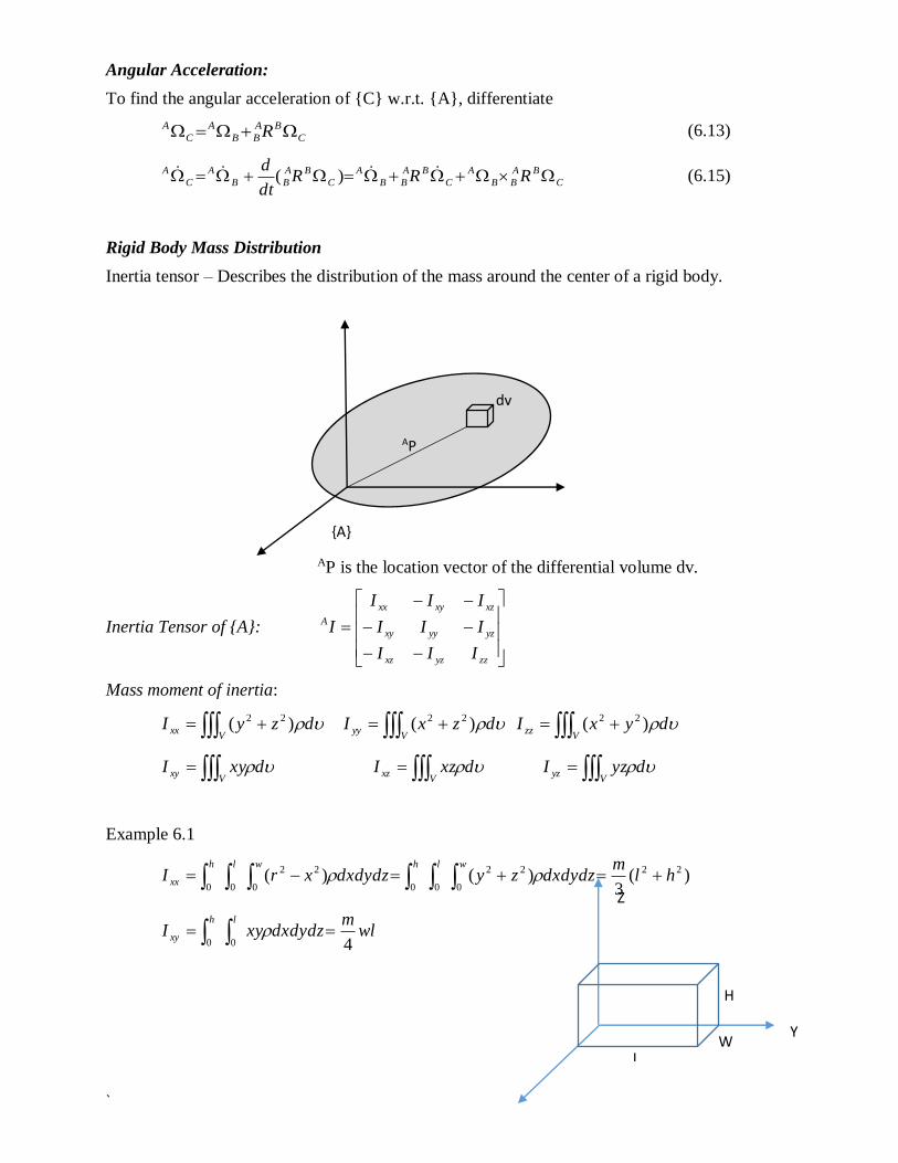
Inertia tensor – Describes the distribution of the mass around the center of a rigid body.
AP is the location vector of the differential volume dv.
Inertia Tensor of {A}:
zzyzxz
yzyyxy
xzxyxx
A
III
III
III
I
Mass moment of inertia:
V
xx dzyI )( 22
Vyy dzxI )( 22
V
zz dyxI )( 22
V
xy dxyI V
xz dxzI V
yz dyzI
Example 6.1
)(3
)()( 22
0
22
000
22
00hl
mdxdydzzydxdydzxrI
wlhwlh
xx
wlm
dxdydzxyIlh
xy400
L W
H
Y
Z
{A}
AP
dv
`
Parallel Axis Theorem:
The moment of inertia at the center of the mass is at the minimum quantity along the axis of
rotation. The moment of inertia of any axis parallel to the axis of rotation is given by
2
czz
C
zz
A rmII
where rc = the distance from the axis in {A} to the center of the mass in {C} and m = the point
mass at the center.
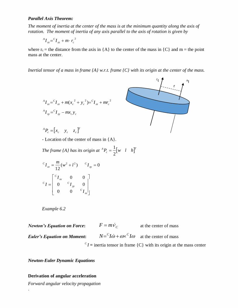
Inertial tensor of a mass in frame {A} w.r.t. frame {C} with its origin at the center of the mass.
222)( czz
C
cczz
C
zz
A mrIyxmII
ccxy
C
xy
A ymxII
Tcccc
A zyxP
- Location of the center of mass in {A}.
The frame {A} has its origin at Tc
A hlwP2
1
)(12
22 lwm
I zz
C 0xy
C I
zz
C
yy
C
xx
C
C
I
I
I
I
00
00
00
Example 6.2
Newton’s Equation on Force: CmF at the center of mass
Euler’s Equation on Moment: IIN CC at the center of mass
IC= inertia tensor in frame {C} with its origin at the mass center
Newton-Euler Dynamic Equations
Derivation of angular acceleration
Forward angular velocity propagation
CI
CI
c
AI
c r

`
1
1
1
1
1
1 ˆ
i
i
ii
ii
ii
i ZR from (5.45)
C
BA
BB
A
C
BA
BB
A
C
A RR from (6.15)
Equating {B} to {A},
C
AA
AA
A
C
AA
AA
A
C
A RR (6.15’)
Rotating {A} w.r.t. {C}
C
AC
AC
A
A
AC
AA
AC
AC
AC
A RRRR )( (6.15’’)
C
C
C
C
A
AC
AA
AC
AC
C RR
Settting {C}={i+1} and 1
1
11
1 ˆ
i
i
ii
i Z from (5.45)
1
1
11
1
1
11
1
1 ˆˆ
i
i
ii
i
ii
ii
ii
ii
ii
i ZZRR (6.32)
For prismatic joints, 0 ii
i , so
i
ii
ii
i R 1
1
1
Derivation of linear acceleration
From (6.12) and by taking similar steps to derive the angular acceleration,
QRVRQRdt
dV BA
BB
A
Q
BA
B
BA
BQ
A )(
)( QRQRVRVV BA
BB
A
B
ABA
BB
A
Q
BA
BrgBO
A
Q
A
Setting {A}={i+1} and {B}={i} and factoring out Ri
i
1 ,
)]([ 11
111
i
i
i
i
i
i
i
i
i
i
i
ii
i
i PPRi (6.34)
For prismatic joints, add two more terms to (6.34) per (6.10)
)]([ 11
1 1
1
i
i
i
i
i
i
i
i
i
i
i
i
i
i PPRi
i 1
1
11
1
11
1 ˆˆ2
i
i
ii
i
ii
i ZdZd (6.35)
Linear acceleration of the center of mass, from (6.12)
Trace the steps taken in applying (6.12),
by setting {A}={B}={i} in (6.12) and iViOrg=0,
)( QRQRVRVV BA
BB
A
B
ABA
BB
A
Q
BA
BrgBO
A
Q
A
i
i
Ci
i
i
i
i
i
Ci
i
i
i
Ci
i vPP )( (6.36)
The inertial force and torque acting at the center of the mass:
From (6.32) and (6.36)
Follow the derivation of (6.32) from (6.15) and (5.45)

`
i
C
ii
C
i
i
IIN
mF
ii
iC
(6.37)
where 3x3 IiC is the inertia tensor in {C} at the center of the body.
H7Backward Iteration for Joint Forces and Torque
Force and torque balance equations at the center of mass of link i:
1
1
1
i
ii
ii
i
i
i fRfF (6.38)
111 )()( i
i
Ci
i
i
i
i
i
Ci
i
i
i
i
i
i
i
i
i fPPfPPnnN (6.39)
0i
i P
Rearranging the equations and adding rotations;
i
i
i
ii
ii
i FfRf
1
1
1 (6.41)
1
1
111
1
1
i
ii
ii
i
i
i
Ci
i
i
ii
ii
i
i
i fRPFPnRNn (6.42)
Finally, the joint torque is the Z component of the vector representing the inertial torque:
i
iT
i
i
i Zn ˆ (6.43)
For prismatic joints, using τ to denote force:
i
iT
i
i
i Zf ˆ (6.44)
{ i+1}
{ C}
{ i} N
F
𝑑𝑉c
dω
ω
`
Forward and backward iterations: Eq (6.45)-(6.53)
Forward - Link velocities and accelerations via the Newton-Euler (6.31)-(6.37).
1
1
1
1
1
1 ˆ
i
i
ii
ii
ii
i ZR (6.45)
1
1
11
1
1
11
1
1 ˆˆ
i
i
ii
i
ii
ii
ii
ii
ii
i ZZRR (6.46)
)]([ 11
111
i
i
i
i
i
i
i
i
i
i
i
ii
i
i PPRi (6.47)
1
1
1
1
1
1
1
1
1
11 )(1
i
i
i
i
i
i
i
i
i
i
i
i
C
i PPi (6.48)
1
1
1
1
1
1
1
1
11
1
1
1
11
1
1
11
1
1
1
1
i
i
i
i
i
i
i
i
i
C
i
i
i
i
i
C
i
i
C
i
ii
i
IIN
IN
mF
i
i
i
(6.49, 6.50)
Backward - Find joint forces and torques via (6.38)-(6.44).
ii
ii
i
i
i
i FfRIf
1
1
1 (6.51)
1
1
111
1
1
i
ii
ii
i
i
i
i
i
i
ii
ii
i
i
i fRPFPnRNn (6.52)
i
iT
i
i
i Zn ˆ (6.53)
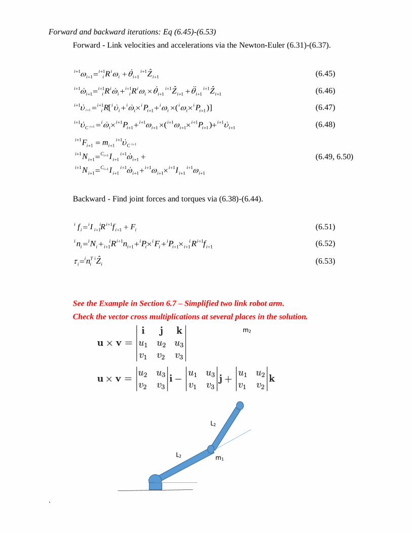
See the Example in Section 6.7 – Simplified two link robot arm.
Check the vector cross multiplications at several places in the solution.
L2
L2
m1
m2
`
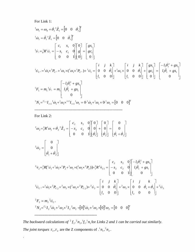
For Link 1:
TZ 11
1
101
1 00ˆ
TZ 11
1
11
1 00ˆ
00
0
100
0
0
1
1
11
11
1
0
11 gc
gs
gcs
sc
R i
i
0000
00
00
00)( 111
1
2
11
1
1
1
11
1
1
11
11
1
1
1
11
1
11111 gsl
gsl
gc
gs
l
kji
l
kji
PP CCC
Ti
i
i
CIIN
gsl
gsl
mmF
i 00000
0
1
1
1
1
1
1
1
1
1
1
1
1
1
1
11
1
111
1
2
11
1
1
11
1
1
1
---------------------------------------------------------------------
For Link 2:
2121
22
22
2
2
21
12
12
2 0
0
0
0
0
0
100
0
0
ˆ
cs
sc
ZR
21
2
2 0
0
0100
0
0
)]([ 111
1
2
11
22
22
1
22
12
2
1
1
1
1
2
1
1
1
1
12
12
2 gsl
gsl
cs
sc
vRPPRv C
2
2
2
212
2
2
12
2
2
2
2
2
2
2
2
2
1
12
00
00
00
00)(2
l
kji
l
kji
PP CCC
TC
C
IIN
mF
00000 2
2
2
2
2
2
2
2
2
2
2
2
2
2
22
2
2
22
2
2
2
-------------------------------------------------
The backward calculations of 1
1
1
1
2
2
2
2 .,. nfnf for Links 2 and 1 can be carried out similarly.
The joint torques 21 , are the Z components of 2
2
1
1 ,. nn .
`
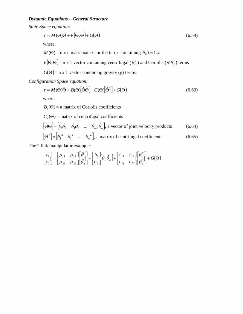
Dynamic Equations – General Structure
State Space equation:
GVM ,)( (6.59)
where,
)(M = n x n mass matrix for the terms containing nii ..1,
,V = n x 1 vector containing centrifugal ( 2
i ) and Coriolis (
ji ) terms
G = n x 1 vector containing gravity (g) terms.
Configuration Space equation:
GCBM 2)()()( (6.63)
where,
)(xB = a matrix of Coriolis coefficients
)(xC = matrix of centrifugal coefficients
nn 13121 ... , a vector of joint velocity products (6.64)
22
1
2
1
2 ... n , a matrix of centrifugal coefficients (6.65)
The 2 link manipulator example:
G
cc
cc
b
b2
2
2
1
2212
1211
21
2
1
2
1
2221
1211
2
1
`
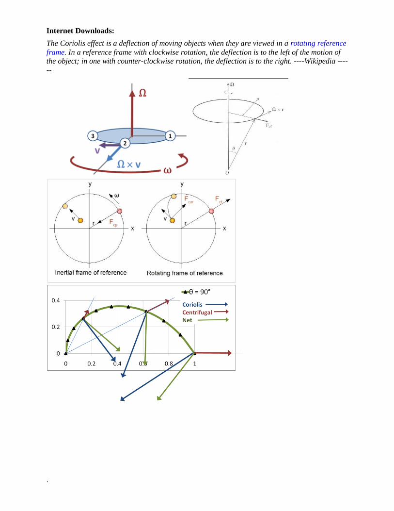
Internet Downloads:
The Coriolis effect is a deflection of moving objects when they are viewed in a rotating reference
frame. In a reference frame with clockwise rotation, the deflection is to the left of the motion of
the object; in one with counter-clockwise rotation, the deflection is to the right. ----Wikipedia ----
--

`
Lagrangian Dynamic Formulation
Quadratic form of manipulator kinetic energy, analogous to k = ½ mv2
Kinetic energy: ii
CiT
iCi
T
Ciii Imk 2
1
2
1 (6.69)
ikk
)(2
1),( Mk T in vector form (6.71)
Potential energy: irefCi
o
ii uPgTmu 0 (6.73)
iuu
Lagrangian The difference between the kinetic energy and the potential energy of a body:
)(),(),( ukL (6.75)
Lagrangian Equation of Motion (as applied to robot arms) derived from Newton’s Law,
LL
dt
d
(6.77)
ukk
dt
d
Example application of Lagrangian equation – Pendulum
Kinetic energy 2)(2
1lmK
Potential energy )cos1( mglU
Lagrangian )cos1()(2
1 2 mgllmUKL
sinmgl
L
2mlL
2ml
L
dt
d
Lagrangian equation:
sin2 mglml
LL
dt
d = 0
g
L
m
θ
`
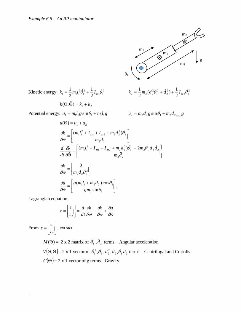
Example 6.5 – An RP manipulator
Kinetic energy: 2
11
2
1
2
1112
1
2
1
zzIlmk 2
12
2
2
2
1
2
2222
1)(
2
1
zzIddmk
21),( kkk
Potential energy: glmglmu 111111 sin gdmgdmumax221222 sin
21)( uuu
22
1
2
2221
2
11 )(
dm
dmIIlmk zzzz
22
22121
2
2221
2
11 2)(
dm
ddmdmIIlmk
dt
d zzzz
2
122
0
dm
k
12
12211
sin
cos)(
gm
dmlmgu,
Lagrangian equation:
ukk
dt
d
2
1
From
2
1
, extract
)(M 2 x 2 matrix of 21 , d terms – Angular acceleration
,V = 2 x 1 vector of 212
2
21
2
1 ,,,, ddd terms – Centrifugal and Coriolis
G = 2 x 1 vector of g terms - Gravity
θ1
m1
m2
m1
m2 g
`
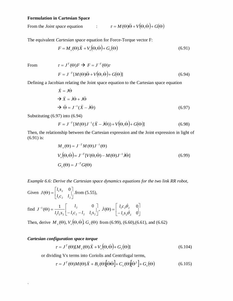
Formulation in Cartesian Space
From the Joint space equation : GVM ,)(
The equivalent Cartesian space equation for Force-Torque vector F:
xxx GVXMF ,)( (6.91)
From FJ T )( )( TJF
],)([ GVMJF T (6.94)
Defining a Jacobian relating the Joint space equation to the Cartesian space equation
JX
JJX
)(1 JXJ (6.97)
Substituting (6.97) into (6.94)
],))()([ 1 GVJXJMJF T (6.98)
Then, the relationship between the Cartesian expression and the Joint expression in light of
(6.91) is:
)()()( 1 JMJM T
x
])(),([, 1 JJMVJV T
x (6.99)
)()( GJG T
x
Example 6.6: Derive the Cartesian space dynamics equations for the two link RR robot,
Given
221
21 0)(
lcl
slJ .from (5.55),
find
21221
2
221
101
)(sllcl
l
sllJ ,
0
0)(
221
221
sl
clJ
Then, derive ),(xM ,, xV )(xG from (6.99), (6.60),(6.61), and (6.62)
Cartesian configuration space torque
],)()[( xxx
T GVXMJ (6.104)
or dividing Vx terms into Coriolis and Centrifugal terms,
xxx
T GCBXMJ 2)()()()( (6.105)
`
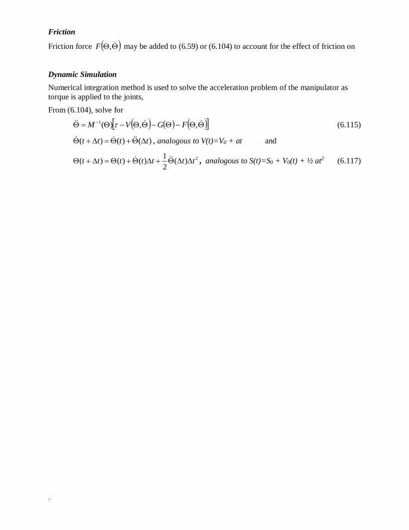
Friction
Friction force ,F may be added to (6.59) or (6.104) to account for the effect of friction on
Dynamic Simulation
Numerical integration method is used to solve the acceleration problem of the manipulator as
torque is applied to the joints,
From (6.104), solve for
,,)(1 FGVM (6.115)
)()()( tttt , analogous to V(t)=V0 + at and
2)(2
1)()()( ttttttt , analogous to S(t)=S0 + V0(t) + ½ at2 (6.117)