chapter 6 detector plan - oregon...movement (i.e. ola in the above example would be assigned to...
TRANSCRIPT

2017 Traffic Signal Design Manual
Oregon Department of Transportation 6-1 June 2017 Traffic Standards and Asset Management Unit Chapter 6 – Detector Plan
Chapter 6 DETECTOR PLAN
Contents
6 Detector plan ................................................................................................................................. 6-3 6.1 Detection Type .............................................................................................................................. 6-3 6.2 Detection Basics ............................................................................................................................ 6-3 6.3 Beyond Basic Detection ................................................................................................................ 6-6
6.3.1 Interchange Ramps ........................................................................................................................... 6-6 6.3.2 Overlap Phase Detection .................................................................................................................. 6-6 6.3.3 Bike Detection .................................................................................................................................. 6-7 6.3.4 Dump Detection ............................................................................................................................... 6-7 6.3.5 Count Detection................................................................................................................................ 6-7 6.3.6 Adaptive Signal Timing Detection ..................................................................................................... 6-7 6.3.7 Other Advanced 2070 Voyage Software Detection .......................................................................... 6-8 6.3.8 Railroad Detection ............................................................................................................................ 6-8
6.4 Standard Detection Layout (Info for all types of detection) ......................................................... 6-9 6.4.1 Mainline Posted Speeds ................................................................................................................... 6-9 6.4.2 Advance Stop Bars ............................................................................................................................ 6-9
6.5 Modifications to Standard Detection Placement ....................................................................... 6-10 6.5.1 Bridge Decks ................................................................................................................................... 6-11 6.5.2 Wide Corner Radius ........................................................................................................................ 6-12 6.5.3 Accesses: Driveways, Streets, and Alleys ........................................................................................ 6-12 6.5.4 Short Minor Street/Driveway Signalized Approaches .................................................................... 6-16
6.6 Detection Input File .................................................................................................................... 6-17 6.6.1 332S Cabinet: 2070 Controller with a C11 Connector .................................................................... 6-19 6.6.2 332 Cabinet: 2070 Controller without a C11 Connector ................................................................ 6-20 6.6.3 332 Cabinet: 170 Controller ........................................................................................................... 6-22 6.6.4 336 Cabinet: 2070 & 170 Controller ............................................................................................... 6-23
6.7 Induction Loop Detection ........................................................................................................... 6-25 6.7.1 Shape/Dimension of the Loops ...................................................................................................... 6-25 6.7.2 Standard Loop Detection Layout .................................................................................................... 6-25 6.7.3 Numbering of the Loops ................................................................................................................. 6-28 6.7.4 When to Re-number Loops ............................................................................................................. 6-32 6.7.5 When and Where to Wire Loops in Series ...................................................................................... 6-35 6.7.6 Loop Wiring Diagram ...................................................................................................................... 6-36 6.7.7 Junction Boxes ................................................................................................................................ 6-40 6.7.8 Number of Loop Wire Turns ........................................................................................................... 6-43 6.7.9 Loop Wire Entrance ........................................................................................................................ 6-46 6.7.10 Loop Feeder Cable .......................................................................................................................... 6-47 6.7.11 Loop Feeder Cable for Retro-Fits .................................................................................................... 6-48 6.7.12 Conduit ........................................................................................................................................... 6-48
6.8 Video Detection .......................................................................................................................... 6-50 6.8.1 Camera Placement and Labeling .................................................................................................... 6-51 6.8.2 Conduit System ............................................................................................................................... 6-52 6.8.3 Standard Video Detection Zone Layout .......................................................................................... 6-52 6.8.4 Wiring Diagram for Video Detection .............................................................................................. 6-55
6.9 Preformed Loops ......................................................................................................................... 6-61 6.10 Radar Detection .......................................................................................................................... 6-62

2017 Traffic Signal Design Manual
Oregon Department of Transportation 6-2 June 2017 Traffic Standards and Asset Management Unit Chapter 6 – Detector Plan
6.10.1 Radar Unit Placement and Labeling................................................................................................ 6-62 6.10.2 Conduit System ............................................................................................................................... 6-64 6.10.3 Standard Radar Detection Zone Layout .......................................................................................... 6-64 6.10.4 Wiring Diagram for Radar Detection .............................................................................................. 6-66
6.11 Microwave Detection .................................................................................................................. 6-69 6.12 Use of Multiple Detection Technologies at a Single Intersection ............................................... 6-69

2017 Traffic Signal Design Manual
Oregon Department of Transportation 6-3 June 2017 Traffic Standards and Asset Management Unit Chapter 6 – Detector Plan
6 DETECTOR PLAN This chapter will discuss all the design elements that are shown on a detector plan sheet, in order of the recommended process for designing a new traffic signal. Design of the detection system typically begins after the signal design. Detection is required for all vehicle phases except when the vehicle phases are recalled in a fixed time cycle (e.g. intersections in a central business district one-way grid system).
6.1 Detection Type ODOT’s default standard detection type is inductive loops based on their high degree of reliability (when installed and maintained properly). Other technologies are available for use and there might be circumstances where alternate vehicle detection is a more logical choice. Alternate detection includes, but is not limited to:
o Video detection o Preformed induction loops o Microwave detection o Radar detection
In order to use alternate detection, concurrence from the ODOT Region Signal Operations Engineer and the ODOT Region Electrical Manager/Supervisor is required. This concurrence should be documented in an e-mail or brief interoffice memo.
Alternate detection devices used on the project must be listed on the approved traffic signal product lists (Green Sheets and/or Blue Sheets). Devices not listed on the Green and Blue sheets require approval from the Traffic Signal Engineer. Note that Microloops are no longer an alternate detection option on state highways (this is a non-invasive conduit system installed by boring under the pavement, whereby sensors are positioned beneath the travel lanes).
6.2 Detection Basics Detection allows the signal controller to service signal phases and provide variable amounts of green time based on the demand for the vehicle phase. Detection needs are determined by the desired signal operation; therefore it is important to have a basic understanding of the signal operation standards that dictate the standards for vehicle detection design.

2017 Traffic Signal Design Manual
Oregon Department of Transportation 6-4 June 2017 Traffic Standards and Asset Management Unit Chapter 6 – Detector Plan
Each signalized intersection is the result of side street (typically City or County road) intersecting with a mainline (state highway). In the case where a state highway intersects with another state highway one route must be designated the mainline and the other route will be the side street. This is usually easy to determine based on traffic volumes, posted speeds and the presence of stop/yield control at the intersection prior to signalization. There cannot be two mainlines or two side streets, there must be one of each designated for each intersection. This fundamental principle results in signal operations that will meet driver expectation; drivers DO NOT expect to stop on a mainline roadway and DO expect to stop on a side street. This designation will be shown in the operational approval based on how the phases are labeled (phases 2 and 6 are mainline through phases and phases 4 and 8 are side street through phases). Figure 6-1 and the following bulleted list show the basic differences in detection used for the mainline, side street, and left turn phases.
Figure 6-1 | Detection Basics – Presence Detection vs. Advanced Detection

2017 Traffic Signal Design Manual
Oregon Department of Transportation 6-5 June 2017 Traffic Standards and Asset Management Unit Chapter 6 – Detector Plan
• For the mainline through phases, the detection is designed to extend green time and protect the dilemma zone (where a vehicle is too close to properly stop at the intersection and too far away to properly get thru the intersection before the yellow terminates). This allows variable green time based on vehicle demand and speed. In order to accomplish this, detection is only placed in advance of the stop bar (often called Advance Detection or Volume-Density Detection). Each vehicle actuation during the mainline green phase will extend the green time such that the vehicle may continue thru the intersection at the posted speed without stopping. This also decreases the chance of a vehicle being within the dilemma zone when the mainline phase turns yellow. There is no need to place detection at the stop line for a mainline through phase because the standard for signal timing is to always recall this phase (e.g. a vehicle actuation is NOT required to bring up the mainline through phases). When only the mainline phases are recalled the signal will “rest” in green on the mainline when there are no vehicle actuations.
• For protected and protected/permissive left turn phases on the mainline, the detection
is treated exactly the same as detection for a side street phase.
• For permissive left turn phases on the mainline, there are two different options based on the lane use:
a. for a left turn only lane, the detection is treated exactly the same as detection for a side street phase. See Figure 6-2.
b. for a shared left-through option lane, the detection is a combination of the mainline through phases and the side street phases; the advance detection used for mainline plus stop bar detection. See Figure 6-3.
Figure 6-2 | Mainline Permissive Left Turn: Option A Figure 6-3 | Mainline Permissive Left Turn:
Option B

2017 Traffic Signal Design Manual
Oregon Department of Transportation 6-6 June 2017 Traffic Standards and Asset Management Unit Chapter 6 – Detector Plan
• For right turn lanes on the mainline, the detection is treated similar to detection for a mainline through phase with the only difference being the spacing of the advance detection.
• For all side street phases, the detection is designed to place a call into the signal
controller when a vehicle approaches on a red indication and extend the green time based on vehicle demand when a vehicle approaches on a green indication. Side street phases are NOT recalled like the mainline through phases, and therefore will not turn green unless there is vehicle demand. Side street phases are also not designed to extend the green time for vehicles traveling at posted speed. Presence detection is placed at the stop bar and just slightly in advance of the stop bar for each lane. Detection for the side street does not allow the same degree of dilemma zone protection as the mainline through phases because of the fundamental difference between driver expectations on a mainline verses a side street.
6.3 Beyond Basic Detection Depending on the location, desired signal operation and other unique circumstances at the intersection, additional detection beyond the basics may need to be considered.
6.3.1 Interchange Ramps For interchange ramps, the detection is treated similar to the detection for a side street phase. The only exception is additional advance detection is also used, based on the higher prevailing speed of a vehicle that has just exited the freeway. Also, “dump” detection may be desired. See section 6.3.4 below for more information on dump detection.
6.3.2 Overlap Phase Detection Overlap phase detection must be assigned to one of the parent phases, as the signal timing software requires that each detection input is assigned to a numbered phase. For example, if a right turn overlap phase “A” has parent phases 1 and 8, the plans cannot just show “OLA” as the phase assignment in the wiring/layout diagrams; the plans must show the detection for OLA as either phase 1 or phase 8.
Typically the overlap phase is assigned to the parent phase that is adjacent to the movement (i.e. OLA in the above example would be assigned to phase 8, not phase 1). However, there may be cases where it is beneficial to assign the overlap detection to the non-adjacent, complementary movement (i.e. OLA could be assigned to phase 1 if this movement had a lot more volume than phase 8). Unique coding can also be done to ensure that the overlap phasing detection functions appropriately. Verify which parent phase should be assigned to the overlap phase detection with the Region Signal Timer.

2017 Traffic Signal Design Manual
Oregon Department of Transportation 6-7 June 2017 Traffic Standards and Asset Management Unit Chapter 6 – Detector Plan
6.3.3 Bike Detection Bike detection should be installed at an intersection where bike lanes are present. If no bike lanes are present, but there is a high volume of bike riders, bike detection may be considered on the shoulder if engineering judgment determines a need. Bike detection for the mainline and for the side street is treated the same as vehicle detection for the main line and side street discussed in Section 6.2. Documentation from the ODOT Region Signal Operations Engineer (such as an operational approval or an e-mail) is required for bike detection installed outside of a bike lane.
6.3.4 Dump Detection Dump detection may be necessary for an interchange ramp to prevent ramp queues from backing up onto the freeway by allowing the signal controller to give priority and extended green time to the ramp phase if the queue reaches a certain point for a certain period of time. Of course, it is always preferable to have the ramp alignment be designed to accommodate the calculated design life 95 percentile queue length, which would eliminate the need for dump detection. However, this is not always feasible. An operational analysis is always required to determine if dump detection is needed and to determine the optimal placement of the detection. Documentation from the ODOT Region Signal Operations Engineer (such as an operational approval or e-mail) is required for use of dump detection.
6.3.5 Count Detection The ability to count actuations provides critical volume data to the signal timer developing the appropriate signal timing parameters throughout the life of the traffic signal. Most detection locations that are placed according to Section 6.2 (for reasons other than counting) can also effectively be used to count traffic. However, there are cases where detection is desired ONLY for count purposes, such as for non-signal controlled right turn slip lanes or for fixed-timed recalled signals in a central business district. The Region Signal Timing staff will provide direction for the use and placement of count detection.
6.3.6 Adaptive Signal Timing Detection Adaptive signal timing detection works much differently than the standard detection discussed in Section 6.2. Typically more detection is needed for adaptive to work properly, as the adaptive software collects more data to use in determining how to operate the signal. When designing a detection system that will be using adaptive signal timing, it is important to follow the software manufacturer’s recommendations for detection placement.
Region Traffic Engineer Approval is required for use of Adaptive Signal Timing.

2017 Traffic Signal Design Manual
Oregon Department of Transportation 6-8 June 2017 Traffic Standards and Asset Management Unit Chapter 6 – Detector Plan
6.3.7 Other Advanced 2070 Voyage Software Detection The 2070 Voyage Software has several features that may require additional detection or modification to the standard detection layout to function properly. The Region Signal Timing staff will provide direction for the use and placement of detection needed to operate the advanced software features. Documentation from the ODOT Region Signal Operations Engineer (such as an operational approval or an e-mail) is recommended for use of advanced 2070 Voyage Software features that require detection modification.
6.3.8 Railroad Detection Depending on the location of the railroad crossing, the intended signal operation, and rail crossing order requirements, additional detection may be necessary. See Chapter 16 for more information on railroad related signal design.
Modifications to the standard detection layout should be documented.

2017 Traffic Signal Design Manual
Oregon Department of Transportation 6-9 June 2017 Traffic Standards and Asset Management Unit Chapter 6 – Detector Plan
6.4 Standard Detection Layout (Info for all types of detection) Standard detection layouts for each type of detection (loop, video, and radar) are shown in in each respective section of this chapter. These values should be used as an initial starting point, but keep in mind that certain site specifics and the type of detection may require some adjustments to these values in order to operate as intended (see Section 6.5 for more info on modifying placement of detection). Always verify the detection layout with Region Signal Timer.
6.4.1 Mainline Posted Speeds The mainline detection is located according to the posted speed. Detection should be based off of the posted speed. The Region Traffic Engineer may approve the use of a speed other than the posted (i.e. design speed, 85th percentile, etc.) if an engineering study determines that the use of a speed other than the posted speed is necessary. If the posted speed is not used, the detector plan sheet should note what speed the detection is based on and reference the engineering study; for example, “Mainline detection based on 85th percentile speed of 40 mph as per Region Traffic Engineer approval dated 1-1-14.” Oftentimes, the location where a speed zone starts or ends is also located at a cross street due to the cross street being an easy reference point. If the project has a speed zone change located at the signalized intersection (or within the influence area of signalized intersection), such that detection placement would be different for each mainline approach, it is recommended to move the starting (or ending) point of the speed zone to just outside the influence area of the intersection. This is recommended for a couple of reasons:
• The detection placement on the mainline is designed for vehicles traveling at uniform speeds. Speed zone changes near a signalized intersection produce inconsistent speeds (either heavy accelerating or decelerating). The signal timing parameters associated with detection cannot account for vehicle acceleration or deceleration.
• The speed zone signing is more likely to be seen and obeyed if it is located separately from the traffic signal. Separating out driving tasks (change of speed followed by obeying the traffic signal) so that the motorist is not overloaded with information is always beneficial.
Coordinate with the Region Traffic Unit if a speed zone change should be considered on the project.
6.4.2 Advance Stop Bars If a crosswalk is present, the near side of the crosswalk bar functions as the stop line for vehicles. Separate, advance stop bars prior to a crosswalk are only used when the geometry of the intersection cannot accommodate the design vehicle’s turning path without them. That said, advance stop bars should not be used in lieu of proper geometric design; the roadway should be designed to accommodate the design vehicle

2017 Traffic Signal Design Manual
Oregon Department of Transportation 6-10 June 2017 Traffic Standards and Asset Management Unit Chapter 6 – Detector Plan
without use of advance stop bars whenever feasible. If an advance stop bar is used, detection should never be placed between the advance stop bar and the crosswalk marking.
6.5 Modifications to Standard Detection Placement There are several site specific issues that need to be considered when placing detection to ensure it can even be installed and that it functions optimally. The following sections discuss common situations where standard detection placement or signal timing parameters (or both) may require modification. Always discuss any site specific considerations with the Region Signal Timing staff to ensure the concern can be properly addressed, but keep in mind that sometimes the occurrence of the event in question may not happen frequently enough to warrant any signal timing or detection placement modification. Always document the reason for any non-standard detection placement. If the standard spacing of any detector location requires modification, the unique spacing value should be noted on the plan as, “Non-standard spacing is intentional” so that other experienced personnel reading the plans know that the value shown is not a typo.

2017 Traffic Signal Design Manual
Oregon Department of Transportation 6-11 June 2017 Traffic Standards and Asset Management Unit Chapter 6 – Detector Plan
6.5.1 Bridge Decks There are only two types of detection that can be used on a bridge deck; preformed loops, which are installed on top of the bridge rebar prior to the deck pour, and non-invasive forms of detection (e.g. video, radar, etc.). The non-invasive forms of detection are the only viable solution for existing bridge decks. If preformed loops are installed on a new bridge, the signal designer will need to coordinate with the bridge designer.
The other option when dealing with detection on a bridge deck is to avoid the bridge deck if possible. If the detection placement can be shifted a small distance without harming the intended signal operations (approx. 30 feet or less), this may be a reasonable solution if non-invasive detection cannot be used. Work with the Region Signal Timer. Figure 6-4 | Detection Placement Considerations: Bridge Decks
Options for Detection on a Bridge Deck: • Use a non-invasive form of detection
(Video or Radar) • Use pre-formed loops that can be
installed prior to the deck pour • Move the detection closer to the stop
bar (and avoid the bridge deck)

2017 Traffic Signal Design Manual
Oregon Department of Transportation 6-12 June 2017 Traffic Standards and Asset Management Unit Chapter 6 – Detector Plan
6.5.2 Wide Corner Radius An intersection with wide radii (typically rural locations that do not have a bike lane), may need additional stop bar detection to accommodate vehicles and bikes that traverse this area. These additional loops should still be located within the lane line striping (never outside the lane line in the shoulder).
Figure 6-5 | Detection Placement Considerations: Wide Radius
6.5.3 Accesses: Driveways, Streets, and Alleys Vehicles accessing driveways streets or alleys near signal detection may result in unintentional actuations that adversely affect the efficiency of the intended signal operation. This can lead to motorist frustration, longer queue lengths, and more traffic congestion. One of the best solutions to improve signal operations and overall safety is to remove or restrict certain movements of any access that is within the influence area of the signalized intersection. Coordinate with the Region Traffic and Access Management Staff to discuss the possibility of removal or restriction of movements. If removal or restriction is not an option, the alternative options presented in the following bulleted items (for the most common issues) should be considered.
Extra stop bar detection for wide radius
2017 Traffic Signal Design Manual
Oregon Department of Transportation 6-13 June 2017 Traffic Standards and Asset Management Unit Chapter 6 – Detector Plan
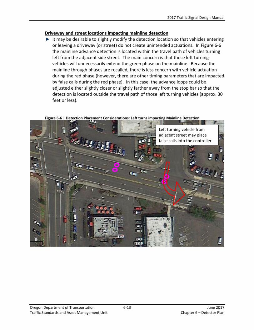
Driveway and street locations impacting mainline detection It may be desirable to slightly modify the detection location so that vehicles entering
or leaving a driveway (or street) do not create unintended actuations. In Figure 6-6 the mainline advance detection is located within the travel path of vehicles turning left from the adjacent side street. The main concern is that these left turning vehicles will unnecessarily extend the green phase on the mainline. Because the mainline through phases are recalled, there is less concern with vehicle actuation during the red phase (however, there are other timing parameters that are impacted by false calls during the red phase). In this case, the advance loops could be adjusted either slightly closer or slightly farther away from the stop bar so that the detection is located outside the travel path of those left turning vehicles (approx. 30 feet or less).
Figure 6-6 | Detection Placement Considerations: Left turns impacting Mainline Detection
Left turning vehicle from adjacent street may place false calls into the controller

2017 Traffic Signal Design Manual
Oregon Department of Transportation 6-14 June 2017 Traffic Standards and Asset Management Unit Chapter 6 – Detector Plan
Similar to the above example, except the mainline advance detection is located within the travel path of vehicles turning right onto the adjacent side street. Again, the main concern is that these right turning vehicles will unnecessarily extend the green phase on the mainline. In this case, the advance loops could be adjusted slightly closer to the stop bar so that the detection is located outside the travel path of those right turning vehicles (approx. 30 feet or less).
Figure 6-7 | Detection Placement Considerations: Right Turns Impacting Mainline Detection
Right turning vehicle into adjacent street may place false calls into the controller

2017 Traffic Signal Design Manual
Oregon Department of Transportation 6-15 June 2017 Traffic Standards and Asset Management Unit Chapter 6 – Detector Plan
Driveway and street locations impacting left turn detection Accesses located within the left turn lane storage area may also cause some issues
with unintended actuations. In Figure 6-8 the mainline left turn phase detection is located within the travel path of vehicles turning left from the driveway access onto the mainline. There are two main concerns; these vehicles turning left into the driveway will either unnecessarily service the left turn phase of the traffic signal or unnecessarily extend the green time of the left turn phase. In this case, the detection placement could be modified to avoid the travel path or the detection (so that both concerns are addressed) or the detectors could be programmed with a delay (so that the more critical concern is unnecessarily serving the phase is addressed).
Figure 6-8 | Detection Placement Considerations: Left Turns Impacting Left Turn Detection

2017 Traffic Signal Design Manual
Oregon Department of Transportation 6-16 June 2017 Traffic Standards and Asset Management Unit Chapter 6 – Detector Plan
6.5.4 Short Minor Street/Driveway Signalized Approaches The standard placement for detection of the minor street is 75 feet, 15 feet and 5 feet. However, if the minor phase approach is short in distance (i.e. to a driveway) or the pavement doesn’t extend very far past the radius, the detection located at 75 feet and 15 feet may be omitted as necessary. See Figure 6-9.
Figure 6-9 | Detection Placement Considerations: Short Minor Street/Driveway Signalized Approaches
Standard minor street detection on a short approach won’t work well. Omit detection at 75’ and possibly at 15’.

2017 Traffic Signal Design Manual
Oregon Department of Transportation 6-17 June 2017 Traffic Standards and Asset Management Unit Chapter 6 – Detector Plan
6.6 Detection Input File It is important to have an understanding of the detection input file because the detector plan sheet shows and details where the detection field wiring is terminated in the detection input file (located in the signal controller cabinet). The following information in this section discusses the default configuration for the detection wiring, which is a good starting point for design. However, each intersection is unique and the signal timer may wish to deviate from the default. The Region Signal Timing staff will provide direction to the signal designer for the appropriate location to terminate the detection wiring. Figure 6-10 thru Figure 6-11 show the location and termination details of the detector input file for the 332 and 332S signal controller cabinet. The detector input file is broken into two files, the “I” file and the “J” file, with each file having either 9 or 10 slots, and each slot having two channels (the “Upper” and the “Lower”). The standard nomenclature for expressing the correct location to terminate the detection is shown as file/slot/channel. For example, if a loop feeder cable is terminated on the terminal block for the “I” file, slot 2, upper channel, it is shown as “I2U”. The following signal timing functions are associated with the input file channels:
• Extend (E) – this function is only active during the green phase of the associated signal phase. It allows the green time to be extended based on the parameters within the signal timing.
• Call (C) – this function is only active during the red phase of the associated signal phase. It allows the signal controller to service the associated signal phase within the parameters of the normal phase rotation; signal phases other than the mainline through phase are only serviced if there is demand.
• Carryover (CO) – also known as “stretch”, this function is only active during the green phase of the associated signal phase. It allows the input of a detector to remain “ON” for a pre-defined amount of time after the actual vehicle actuation; effectively elongating the size of the detection zone.
• Delay (D) – this function is only active during the red phase of the associated signal phase. It allows the input of a detector to remain “OFF” for a pre-defined amount of time during the actual vehicle actuation; reducing the chance of unnecessarily serving a phase from unintended actuations (e.g. vehicles turning right on red).
• Count – this function simply counts the number of actuations. The count feature provides data that is essential to developing appropriate signal timing.
Note: The input file does NOT contain any standard slots for overlap phases. The detection for overlap phases should be assigned to one of the parent phases.

2017 Traffic Signal Design Manual
Oregon Department of Transportation 6-18 June 2017 Traffic Standards and Asset Management Unit Chapter 6 – Detector Plan
Figure 6-10 | 332 and 336 Signal Controller Cabinet Detection Input File Location
Detector Amplifier (used for loop detection)
Detector Amplifier (used for loop detection)
336 Cabinet
332 Cabinet

2017 Traffic Signal Design Manual
Oregon Department of Transportation 6-19 June 2017 Traffic Standards and Asset Management Unit Chapter 6 – Detector Plan
6.6.1 332S Cabinet: 2070 Controller with a C11 Connector In 332S cabinets with a C11 connector, there are no connection limitations for the input file. There is also an additional slot (10) that is available for use. This results in a total of 40 inputs. Thirty two of the inputs have full signal timing functionality (E, C, CO, D and count). Eight of the inputs have limited functionality (E, C, and count only). The default phasing for each channel as shown in Figure 6-11, is based on the ring and barrier diagram layout for easy troubleshooting. Each odd phase has a total of four inputs and each even phase has a total of 6 inputs. This should meet the needs of the majority of intersections without having to reassign any default phases in the software. However, if the default phases do need to be modified, the plans should only show the new, correct phase (do not show or reference the default phase).
Figure 6-11 | 332S Detection Input File Details for 2070 Controller with a C11 Connector
14 1 21 9 16 3 23 11 18 X
X 5 30 X X 7 32 X 20 X
13 2 22 10 15 4 24 12 17 X
X 6 31 X X 8 SP7 X 19 X
Slot Number * VD # has limited functionalities (Call, Extend, & Count only)# SCATS Det # Each VD # without an astericks has full functionality (Extend,
Slot Function Call, Carryover, Delay, & Count)
C1 Pin #Voyage Detector # Definitions: SCATS Function SCATS=Sydney Coordinated Adaptive Traffic System
7 8 9 10
"I"
File
Upp
er
1 2 3 4 5 6
Ph 3 Ph 4 Ph 4 Ph 4Ph 1 Ph 1 Ph 2 Ph 2 Ph 2 Ph 3
C11-18 C1-41 C1-65 C1-49C1-56 C11-16 C1-39 C1-63 C1-47 C1-58
VD 32 VD 14 VD 16 VD 18VD 1 VD 29 VD 9 VD 11 VD 13 VD 3
Ph 2 Ph 3 Ph 3 Ph 4 Ph 4 Ph 4
Low
er
Ph 1 Ph 1 Ph 2 Ph 2C11-22 C1-45 C1-78 C11-12C1-60 C11-20 C1-43 C1-76 C11-10 C1-62
VD 33* VD 15 VD 17 VD 34*VD 2 VD 30 VD 10 VD 12 VD 31 VD 4
PB6 PB6PB6 PB6 PB6 PB6 PB6 PB6
5 6 7 8 9 10
"J"
File U
pper
1 2 3 4
C1-59 C11-19 C1-44 C1-77
Ph 7 Ph 8 Ph 8 Ph 8Ph 5 Ph 5 Ph 6 Ph 6 Ph 6 Ph 7C1-66 C1-50C1-55 C11-15 C1-40 C1-64 C1-48 C1-57 C11-17 C1-42
VD 28VD 5 VD 35* VD 19 VD 21 VD 23 VD 7 VD 38* VD 24 VD 26
C1-46 C1-79 C11-13
Ph 8 Ph 8
Low
er Ph 5 Ph 5 Ph 6 Ph 6 Ph 6 Ph 7 Ph 7 Ph 8
PB6
VD 39* VD 25 VD 27 VD 40*
PB6
VD 6 VD 36* VD 20 VD 22 VD 37* VD 8
C11-11 C1-61 C11-21
VD #XXX
#
Fn
C1-##
SP7 PB6PB7 PB6 PB6

2017 Traffic Signal Design Manual
Oregon Department of Transportation 6-20 June 2017 Traffic Standards and Asset Management Unit Chapter 6 – Detector Plan
6.6.2 332 Cabinet: 2070 Controller without a C11 Connector With controller cabinets that do not have a C11 connector there are some connection limitations which result in a total of 8 slots (I1, I4, I5, I8, J1, J4, J5, and J8) where the upper and lower channel provide only a single input to the controller (rather than the normal two inputs per slot). See Figure 6-12. For example if one detector is wired to I1U and a different detector is wired to I1L, the controller will only receive one input and cannot differentiate between which detector is generating the input. This results in these two detectors essentially operating as one single detection zone. While theoretically it doesn’t matter which channel a single detector is wired to for these 8 slots (both the upper and lower channel produce the same single input to the controller), the channel location still needs to be defined on the plan sheet to provide direction to the contractor and consistency. Typically, a single detector wired to one of these 8 slots will be shown as terminating on the upper channel. There are a total of 28 detector inputs available, each with full signal timing functionality (E, C, CO, D, and Count). Each input is associated with a signal phase. The standard default phasing for each channel is shown in Figure 6-12, but the phases and signal timing functions for each channel can very easily be assigned as necessary in the current Voyage software. The voyage detector numbers and C1 pin numbers are constant and do not change. If the standard default phases need to be modified, the plans should only show the new, correct phase (do not show or reference the default phase).

2017 Traffic Signal Design Manual
Oregon Department of Transportation 6-21 June 2017 Traffic Standards and Asset Management Unit Chapter 6 – Detector Plan
Figure 6-12 | 332 Detection Input File Details for 2070 Controller without a C11 Connector
14 1 21 9 16 3 23 11 18
5 30 7 32 20
13 2 22 10 15 4 24 12 17
6 31 8 SP7 19
Slot Number Each VD # has full functionality (Extend, # SCATS Det # Call, Carryover, Delay, & Count)
Slot Function
C1 Pin #Voyage Detector # Definitions: SCATS Function SCATS=Sydney Coordinated Adaptive Traffic System
Fn
C1-##VD #XXX
SP7
#
VD 22 VD 25 VD 27 VD 8
PB7
Low
er Ph 6 Ph 6 Ph 8 Ph 8 Ph 7C1-44 C1-77 C1-46 C1-79 C1-61
VD 20
Ph 7 Ph 8C1-66 C1-50 C1-59
VD 5 VD 19 VD 21 VD 23 VD 7 VD 24 VD 26 VD 28 VD 6
PB8
Ph 8 Ph 8 Ph 5
"J"
File U
pper
1 2 3 4
VD 17 VD 4
5 6 7 8 9
C1-55 C1-40 C1-64 C1-48 C1-57 C1-42
Ph 5 Ph 6 Ph 6 Ph 6
Ph 3C1-43 C1-76 C1-45 C1-78 C1-62
VD 10 VD 12 VD 15Low
er
Ph 2 Ph 2 Ph 4 Ph 4
PB6
VD 1 VD 9 VD 11 VD 13 VD 3 VD 14 VD 16 VD 18 VD 2
C1-56 C1-39 C1-63 C1-47 C1-58 C1-41 C1-65 C1-49 C1-60
Ph 1 Ph 2 Ph 2 Ph 2 Ph 3 Ph 4 Ph 4 Ph 4 Ph 1
"I"
File
Upp
er1 2 3 4 5 6 7 8 9

2017 Traffic Signal Design Manual
Oregon Department of Transportation 6-22 June 2017 Traffic Standards and Asset Management Unit Chapter 6 – Detector Plan
6.6.3 332 Cabinet: 170 Controller The available signal timing functions of each channel are very limited. For instance, only certain channels have the ability to count and some channels only have a couple of function. See Figure 6-13. This creates the need for software input transfers and additional internal logic for the detection to operate properly, especially at large intersections with a large number of loops. If the project involves older existing controller and software (170 signal controller with Wapiti software) information on input transfers, if needed, will be shown on the detector plan sheet. However, all 170 controllers should be upgraded to the current standard if possible. Figure 6-13 | 332 Detection Input File Details for 170 Controller
14 1 21 9 16 3 23 11 18
5 30 7 32 20
13 2 22 10 15 4 24 12 17
6 31 8 SP7 19
Slot Number * Input has limited functionalities# SCATS Det #
Slot Function Definitions:
C1 Pin # SCATS=Sydney Coordinated Adaptive Traffic SystemTiming Functions E = extend CO = CarryoverSCATS Function C = Call D = Delay
ct. = Count
D, ct. D, ct. CO,D
D, ct. D, ct.
D, ct.
CO,D CO,D
CO,D
Fn
C1-##Fn
E,CO E,C,
Ph 4 Ph 3
CO,D
D, ct. CO,D
D, ct.
D, ct.
D, ct. D, ct. CO,D
XXX
CO,DD, ct.D, ct.
SP7
C1-46 C1-79 C1-61
C1-66 C1-50 C1-59
5 6 7 8 9
#
E,C,CO, E,CO E,C,
PB7
Ph 8 Ph 7C1-44 C1-77
Low
er
Ph 6 Ph 6
E,C, C, D E,C,
E,C,CO, E,CO
Ph 8
C1-40 C1-64 C1-48 C1-57 C1-42
Ph 5 Ph 6 Ph 6 Ph 6 Ph 7 Ph 8
PB8
"J"
File
Upp
er
1 2 3 4
Low
er
E,C,CO, E,C,CO, E,C, C, D E,C,CO, E,C,CO,
Ph 8 Ph 8 Ph 5C1-55
PB6
C1-78 C1-62
E,C,CO, E,CO E,C,CO,
C1-43 C1-76 C1-45
Ph 2 Ph 2 Ph 4
E,C,CO, E,C,CO, E,C, C, D E,C,CO, E,C,CO, E,C, C, D E,C,
C1-56 C1-39 C1-63 C1-47 C1-58 C1-41 C1-65 C1-49 C1-60
Ph 1 Ph 2 Ph 2 Ph 2 Ph 3 Ph 4 Ph 4 Ph 4 Ph 1
"I"
File
Upp
er
1 2 3 4 5 6 7 8 9

2017 Traffic Signal Design Manual
Oregon Department of Transportation 6-23 June 2017 Traffic Standards and Asset Management Unit Chapter 6 – Detector Plan
6.6.4 336 Cabinet: 2070 & 170 Controller Figure 6-14 shows the details of the detector input file for the 336 signal controller cabinet with a 2070 controller. There is only one input file in a 336 cabinet with 10 slots and 20 channels, for a total of 20 detector inputs. Each input has full signal timing functionality (E, C, CO, D, & Count). The standard nomenclature for expressing the correct location to terminate is slot/channel, for example “2U”. The 336 cabinet with a 170 controller is the same as a 336 cabinet with a 2070 controller, with one exception: eight of the inputs do not have the count function. See Figure 6-15. All 170 controllers should be upgraded to the current standard (2070 controller and Voyage software) if possible. Figure 6-14 | 336 Detection Input File Details for 2070 Controller
14 1 16 3 13 2 15 4 21 23
18 5 20 7 17 6 19 8 22 24
Slot Number Each VD # has full functionality (Extend, # SCATS Det # Call, Carryover, Delay, & Count)
Slot Function
C1 Pin # Definitions: Voyage Detector # SCATS=Sydney Coordinated Adaptive Traffic System
C1-##VD#
#
VD 21 VD 26
Fn
Ph 6 Ph 8C1-60 C1-43 C1-62 C1-45 C1-59 C1-44 C1-61 C1-46 C1-64 C1-66
Low
er
Ph 1 Ph 2 Ph 3 Ph 4 Ph 5 Ph 6 Ph 7 Ph 8
VD 2 VD 10 VD 4 VD 15 VD 6 VD 20 VD 8 VD 25
C1-65
VD 1 VD 9 VD 3 VD 14 VD 5 VD 19 VD 7 VD 24 VD 11 VD 16
C1-56 C1-39 C1-58 C1-41 C1-55 C1-40 C1-57 C1-42 C1-63
Ph 4Ph 1 Ph 2 Ph 3 Ph 4 Ph 5 Ph 6 Ph 7 Ph 8 Ph 2
Upp
er
1 2 3 4 5 6 7 8 9 10

2017 Traffic Signal Design Manual
Oregon Department of Transportation 6-24 June 2017 Traffic Standards and Asset Management Unit Chapter 6 – Detector Plan
Figure 6-15 | 336 Detection Input File Details for 170 Controller
14 1 16 3 13 2 15 4 21 23
18 5 20 7 17 6 19 8 22 24
Slot Number * Input has limited functionalities (has all functions, except# SCATS Det # the count function)
Slot Function
C1 Pin # Definitions: SCATS=Sydney Coordinated Adaptive Traffic System
#
Fn
C1-##
Ph 6 Ph 8C1-60 C1-43 C1-62 C1-45 C1-59 C1-44 C1-61 C1-46 C1-64 C1-66
Low
er
Ph 1 Ph 2 Ph 3 Ph 4 Ph 5 Ph 6 Ph 7 Ph 8
C1-65C1-56 C1-39 C1-58 C1-41 C1-55 C1-40 C1-57 C1-42 C1-63
Ph 4Ph 1 Ph 2 Ph 3 Ph 4 Ph 5 Ph 6 Ph 7 Ph 8 Ph 2
Upp
er1 2 3 4 5 6 7 8 9 10

2017 Traffic Signal Design Manual
Oregon Department of Transportation 6-25 June 2017 Traffic Standards and Asset Management Unit Chapter 6 – Detector Plan
6.7 Induction Loop Detection Loop detection technology has been around since the 1960’s and still remains a popular choice for detection despite the growing technology of other detection systems. Loop detection is the ODOT standard for several reasons:
• Precise and predictable area can be defined for the detection zone • Independent of environment (weather, lighting, and sound) • Most accurate and reliable technology when installed properly • Cost effective • Simple maintenance
Loop detection works using induction. When the loop wire is coiled and a current is applied to the coil, a magnetic field is produced. A vehicle entering the magnetic field causes the inductance of the loop to decrease. This change in inductance is measured and used to provide an input into the signal controller, indicating the presence of a vehicle.
6.7.1 Shape/Dimension of the Loops The standard dimension and shape of a vehicle loop is either a 6 foot round or a 4 foot diamond, contractor choice. A Bicycle loop is a 2½ foot diamond.
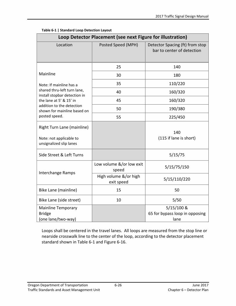
6.7.2 Standard Loop Detection Layout The standard loop detection layout has been developed by the Traffic Signal Operations Unit and is shown below in Table 6-1 and Figure 6-16. This standard is based on desired signal operation and economy. Prior to non-invasive technologies (such as video and radar which do not require embedment into the pavement), invasive technologies (such as loops which are cut into the pavement) dictated the need to balance the number (and size) of detection zones installed with the desired signal operation. There were also a limited number of inputs into the signal controller and those inputs were further limited to certain functions in the old Wapiti signal software. Because of these limitations, very specific standards were developed for detection layout and termination in the controller cabinet.
Many of these constraints are no longer an issue with the current signal controllers, software, and alternate detection technologies which allows much more flexibility in how the detection can function. While these constraints have eased the burden of detection layout and allow many workable options, the standard for detector layout has remained largely unchanged due to the many years of cost effective and acceptable performance we have experienced.
2017 Traffic Signal Design Manual
Oregon Department of Transportation 6-26 June 2017 Traffic Standards and Asset Management Unit Chapter 6 – Detector Plan
Table 6-1 | Standard Loop Detection Layout
Loops shall be centered in the travel lanes. All loops are measured from the stop line or nearside crosswalk line to the center of the loop, according to the detector placement standard shown in Table 6-1 and Figure 6-16.
Loop Detector Placement (see next Figure for illustration) Location Posted Speed (MPH) Detector Spacing (ft) from stop
bar to center of detection
Mainline Note: If mainline has a shared thru-left turn lane, install stopbar detection in the lane at 5’ & 15’ in addition to the detection shown for mainline based on posted speed.
25 140
30 180
35 110/220
40 160/320
45 160/320
50 190/380
55 225/450
Right Turn Lane (mainline) Note: not applicable to unsignalized slip lanes
140 (115 if lane is short)
Side Street & Left Turns 5/15/75
Interchange Ramps
Low volume &/or low exit speed 5/15/75/150
High volume &/or high exit speed 5/15/110/220
Bike Lane (mainline) 15 50
Bike Lane (side street) 10 5/50
Mainline Temporary Bridge (one lane/two-way)
5/15/100 &
65 for bypass loop in opposing lane

2017 Traffic Signal Design Manual
Oregon Department of Transportation 6-27 June 2017 Traffic Standards and Asset Management Unit Chapter 6 – Detector Plan
Figure 6-16 | Standard Loop Detection layout illustration

2017 Traffic Signal Design Manual
Oregon Department of Transportation 6-28 June 2017 Traffic Standards and Asset Management Unit Chapter 6 – Detector Plan
6.7.3 Numbering of the Loops Loops are numbered in a specific way to aid in creating the loop wiring diagram and for ease of reading the plans. It is important to follow the standard numbering convention whenever possible. There are cases where it may be OK to deviate from the standard numbering convention. See Section 6.7.4 for more information on deviating from standard numbering convention. Number the loops starting from the back loop (in the outside lane, loop #1) for Phase 2. Use the following rules to label the remaining loops:
• If the mainline through phase has more than one loop per lane, label all back loops first, then label all the front loops.
• Mainline through loops are numbered before the adjacent left-turn phase. • Mainline right turn lanes are typically wired to the adjacent through phase
(in Figure 6-19, this would be phase 2) and as such, should be numbered before the adjacent left-turn phase.
• Bicycle loops associated with the through phase are numbered after the through phase vehicle loops, (and before the left turn phase loops).
• After labeling the mainline (phase 2) approach, continue clockwise to next approach.
• On the side street approaches, start labeling from the back loop (in the outside lane, regardless of phase)
• Label the back loops first, and the stop bar loops second for each phase. • Side street through phase loops are numbered before the adjacent left-turn
phase. • Loops to be wired in series shall be numbered sequentially to simplify the
loop wiring diagram. See Section 6.7.5 on when to wire loops in series. Figure 6-17 through Figure 6-19 show the basic approach for numbering mainline loop detection. Figure 6-20 through Figure 6-22 show the basic approach for numbering side street loop detection.
Figure 6-17 | Loop Numbering – Mainline example 1

2017 Traffic Signal Design Manual
Oregon Department of Transportation 6-29 June 2017 Traffic Standards and Asset Management Unit Chapter 6 – Detector Plan
Figure 6-18 | Loop Numbering – Mainline example 2
Figure 6-19 | Loop Numbering – Mainline example 3

2017 Traffic Signal Design Manual
Oregon Department of Transportation 6-30 June 2017 Traffic Standards and Asset Management Unit Chapter 6 – Detector Plan
Figure 6-20 | Loop Numbering – Side Street example 1
Figure 6-21 | Loop Numbering – Side Street example 2

2017 Traffic Signal Design Manual
Oregon Department of Transportation 6-31 June 2017 Traffic Standards and Asset Management Unit Chapter 6 – Detector Plan
Figure 6-22 | Loop Numbering – Side Street Example 3
2017 Traffic Signal Design Manual
Oregon Department of Transportation 6-32 June 2017 Traffic Standards and Asset Management Unit Chapter 6 – Detector Plan
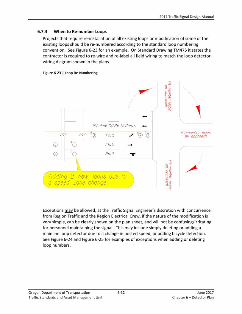
6.7.4 When to Re-number Loops Projects that require re-installation of all existing loops or modification of some of the existing loops should be re-numbered according to the standard loop numbering convention. See Figure 6-23 for an example. On Standard Drawing TM475 it states the contractor is required to re-wire and re-label all field wiring to match the loop detector wiring diagram shown in the plans.
Figure 6-23 | Loop Re-Numbering
Exceptions may be allowed, at the Traffic Signal Engineer’s discretion with concurrence from Region Traffic and the Region Electrical Crew, if the nature of the modification is very simple, can be clearly shown on the plan sheet, and will not be confusing/irritating for personnel maintaining the signal. This may include simply deleting or adding a mainline loop detector due to a change in posted speed, or adding bicycle detection. See Figure 6-24 and Figure 6-25 for examples of exceptions when adding or deleting loop numbers.

2017 Traffic Signal Design Manual
Oregon Department of Transportation 6-33 June 2017 Traffic Standards and Asset Management Unit Chapter 6 – Detector Plan
Figure 6-24 | Loop Re-Numbering Exception – Adding Loops
Figure 6-25 | Loop Re-Numbering Exception – Deleting Loops

2017 Traffic Signal Design Manual
Oregon Department of Transportation 6-34 June 2017 Traffic Standards and Asset Management Unit Chapter 6 – Detector Plan
If a new loop should be wired in series to any existing loops, this will require re-numbering as loops wired in series shall be sequentially numbered in all cases. Under no circumstances should letters be added on to the loop number, such as “11A”, to work around the sequential number requirement for loops wired in series. Figure 6-26 | Loop Re-Numbering – Loops in Series

2017 Traffic Signal Design Manual
Oregon Department of Transportation 6-35 June 2017 Traffic Standards and Asset Management Unit Chapter 6 – Detector Plan
6.7.5 When and Where to Wire Loops in Series Depending on the location and the intended function of the loop, it may provide an individual input to the signal controller or it may be wired in series with one or more loops (combined with other loops to produce a single input to the signal controller). Except as discussed below, all loops should provide an individual input if possible. No more than 3 loops should be wired in series due to the reduction in sensitivity of the loops.
The following loops should be wired in series:
The two loops located at 5 feet and 15 feet from the stop bar The two bike loops located at 5 feet and 50 feet from the stop bar (on the
side street) The following loops are typically wired in series:
The two (or more) loops for the mainline through phase that are nearest the stop line when multiple through lanes are present. See Figure 6-27.
Additional stop line loops. See Figure 6-28. Figure 6-27 | Loops Typically wired in Series: Example 1
Figure 6-28 | Loops Typically Wired in Series: Example 2

2017 Traffic Signal Design Manual
Oregon Department of Transportation 6-36 June 2017 Traffic Standards and Asset Management Unit Chapter 6 – Detector Plan
Loops are usually wired in series for the following reasons: a lack of inputs (20 inputs for a 336 cabinet, 28 inputs for 332 cabinet
without a C11 connector, and 40 inputs for a 332L cabinet with a C11 connector),
the limited functionality of input channel (this applies mainly to 170 signal controllers using Wapiti software), and/or
no operational advantage to have separate inputs. there is also an issue of economy; typically less loop feeder cable is needed
when loops are wired in series which may result in a smaller diameter conduit and less loop detector amplifiers in the controller cabinet. However, the issue of economy should NOT carry much weight when compared to the need for the most efficient signal operation.
When loops are wired in series, there are two locations where this can occur:
In the junction box nearest the loop entrance (standard location). This allows the use of a single loop feeder cable from the junction box to the signal controller cabinet for the most economical installation. Use this option unless directed otherwise.
In the signal controller cabinet (only used in special cases). This requires two (or more) loop feeder cables from junction box to the signal controller cabinet. The only advantage this option has over the standard location is that it provides the flexibility to easily separate the loops wired in series in the future (without having to pull an additional loop feeder cable). The region signal timer will provide direction if having this future capability is necessary.
6.7.6 Loop Wiring Diagram The loop wiring diagram traces each loop by number back to the signal controller cabinet and shows the input location for each loop in the detector input file. This chart is also used to show how many loops need to be installed (bike and vehicular), which loops are wired in series, the location where the loops are wired in series, and where they are located. See Figure 6-29 for a complete example of a loop wiring diagram, with the components discussed below. The loop wiring diagram shows the loop that is served in the left-most column, in sequential order. The next column to the right shows distance in feet from the stop bar to the center of that loop. The rectangle shown in the loop wiring diagram represents the controller cabinet. When loops are wired in series in the junction box, the lines (i.e. loop feeder cables) are shown “joined” together on the outside of the rectangle. When loops are wired in series in the controller cabinet, the lines are shown joined together inside of the rectangle. See Figure 6-30 for how to show loops wired in series in the controller

2017 Traffic Signal Design Manual
Oregon Department of Transportation 6-37 June 2017 Traffic Standards and Asset Management Unit Chapter 6 – Detector Plan
cabinet. Also see Section 6.7.5 for information on when and where to wire loops in series. Bike loops are specified on the loop wiring diagram for added emphasis, as they are physically smaller than vehicular loops. Phase, slot, and voyage detector number are all shown inside of the rectangle. The phase column shows the phase each loop(s) is serving. If the default phase for the slot is to be reassigned to another phase, only show the reassigned phase (do NOT include the default phase, which was the standard practice in the past). See Figure 6-31 for how to show a reassigned phase. The slot column shows where the loop feeder cable will terminate in the signal controller cabinet. The voyage detector number is a unique number that is assigned to each channel in the detector input file for software purposes. The voyage detector number always directly correlates to the slot location and never changes. See Section 6.6 for more info on the detection input file. Figure 6-29 | Loop Wiring Diagram Example

2017 Traffic Signal Design Manual
Oregon Department of Transportation 6-38 June 2017 Traffic Standards and Asset Management Unit Chapter 6 – Detector Plan
Figure 6-30 | Loop Wiring Diagram: Loops wired in series in the Controller Cabinet
Figure 6-31 | Loop Wiring Diagram: Reassigned Phases
If the project has existing 170 controllers with Wapiti software, input call transfers may be necessary for the detection system to function properly. Input call transfers are designated to the right of the rectangle and are a function of the signal controller software. The Region Signal Timer will provide direction for the correct transfers. See Figure 6-32 for how to show input transfers. Note that the voyage number column is deleted as it is not applicable to Wapiti software. If the project is using a 2070 controller, input call transfers are not needed due to the flexibility of functions and phase assignment in the Voyage software.
Figure 6-32 | Loop Wiring Diagram: Input Transfers for 170 Controllers

2017 Traffic Signal Design Manual
Oregon Department of Transportation 6-39 June 2017 Traffic Standards and Asset Management Unit Chapter 6 – Detector Plan
The loop wiring diagram is typically shown on the detector plan sheet in its entirety, even if the project involves work on only a certain number of the loops and not all the loops are graphically shown on the plan sheet. While this isn’t necessary for the contract work, it is extremely helpful to the signal timer, maintenance staff, and future designer using the as-built plans so that multiple past plan sheets (from multiple past projects) are not needed to determine the total number of loops and their termination. Loops that are to be retained and protected are labeled as “NO WORK” on the left side of the loop wiring diagram, either bracketed if space allows or directly next to the loop number. See Figure 6-33 for how to show no work areas. Figure 6-33 | Loop Wiring Diagram: No Work Areas
If an exception for re-numbering loops has been granted and existing loops are being deleted (see Section 6.7.4 for more information on re-numbering loops), the loop wiring diagram will need to indicate that those old loop numbers are out-of-service to avoid confusion in the future. See Figure 6-34 for how to show out-of-service loop numbers. Figure 6-34 | Loop Wiring Diagram: Loop Re-Numbering Exception

2017 Traffic Signal Design Manual
Oregon Department of Transportation 6-40 June 2017 Traffic Standards and Asset Management Unit Chapter 6 – Detector Plan
6.7.7 Junction Boxes In addition to the information on conduits in Chapter 5, the following information on junction boxes pertains only to the detection system. Each approach to the intersection that will be served by loop detection will need junction boxes.
Loop wires will only be spliced to the intended loop feeders in the first junction box that they enter from the street. No other signal wires shall be spliced at any point. For loop detection located within 50 feet of the stop line, the junction boxes placed in the signal plan for the wiring of the signal poles should be used. The minimum size junction box is a JB-2 for all quadrants without a signal controller cabinet, and a JB-3T for the quadrant with the signal control cabinet. Note in the Figure 6-35 that the junction boxes in each quadrant are placed around the radius closest to where the loop detectors are located on the approach (as opposed to being located on the other end of the radius). This allows for the most economical installation.
Figure 6-35 | Junction Box Location for Loop Detection – Loops within 50 feet of the Stop Line

2017 Traffic Signal Design Manual
Oregon Department of Transportation 6-41 June 2017 Traffic Standards and Asset Management Unit Chapter 6 – Detector Plan
For loop detection located beyond 50 feet from the stop line, junction boxes should be placed near the same station as where the loop is located. Normally these can be a JB-1. Loops that are located within 50 feet of each other may use the same junction box, with the junction box located at a station between the loops. See Figure 6-36
Figure 6-36 | Junction Box Location for Loop Detection - Loops 50 feet Beyond the Stop Line

2017 Traffic Signal Design Manual
Oregon Department of Transportation 6-42 June 2017 Traffic Standards and Asset Management Unit Chapter 6 – Detector Plan
If the project involves modifying the existing loop detector location, such as to accommodate a speed zone change, the location of the existing junction boxes must also be considered. Generally, the length of the sawcut for the loop wires to the junction box should be held to a minimum, as this particular part of the loop installation is very vulnerable to damage. New junction boxes should be placed if the station of the new loop location is more than 50 feet from the station of the existing junction box. See Figure 6-37.
Figure 6-37 | Junction Box Location for Loop Detection – Modifying Existing Loop Location
Cast Iron Junction Boxes (JB-4 through JB-8) Cast iron junction boxes are used when a junction box must be placed on a bridge. They should not be used in any other circumstance. When bringing loops into cast iron junction boxes via saw cuts through the side, the following recommendations should be followed (see Standard Detail DET4434):
• 2 twisted pair of loop wires in 4-inch deep box in one saw slot • 4 twisted pair of loop wires in 6-inch deep box in one saw slot • 8 twisted pair of loop wires in 8-inch deep box in one saw slot • Non-street box: Multiple cuts in same box require 2-inch spacing away from edges and
2-inch spacing between cuts • Street box: Multiple cuts in same box require 1-inch spacing away from edges and 1-inch
spacing between cuts ( two cuts max per side for a total of 4 twisted pair of loop wires per side)

2017 Traffic Signal Design Manual
Oregon Department of Transportation 6-43 June 2017 Traffic Standards and Asset Management Unit Chapter 6 – Detector Plan
6.7.8 Number of Loop Wire Turns The standard number of turns of loop wire is five as per standard drawing TM475 shown in Figure 6-38. Five turns of wire is typically adequate to provide the proper change in inductance for any loop(s) placed according to the standard detection layout discussed in Section 0. There are cases where additional turns of wire may be required to create an acceptable change in inductance (typically this applies to ramp meter and temporary one-lane, two-way installations due to the long distance of the loop lead-in wire). In other cases less turns of wire may be adequate for proper loop function; but for consistency and less probability of installation errors, the standard five turns of loops should be used. Figure 6-38 | Standard Number of Turns: Std. Dwg. TM475
The standard five turns of loop wire should be used for all loops unless ADDITIONAL turns are required for proper functioning. If additional turns are required, the plan sheets should specifically note which loop(s) and how many turns are required. Check to make sure pavement thickness can accommodate the additional turns of wire.

2017 Traffic Signal Design Manual
Oregon Department of Transportation 6-44 June 2017 Traffic Standards and Asset Management Unit Chapter 6 – Detector Plan
As stated in previous sections, loop detection works due to a change in inductance. The total inductance seen at the detector amplifier (located inside the controller cabinet) is the combination of the inductance of the loop(s) itself and the inductance of the loop lead in wire and loop feeder cable (from the perimeter of the loop to controller cabinet). The design objective of a properly designed loop system is for the detector amplifier to see the greatest amount of inductance change in the loop itself. This is accomplished by always ensuring the inductance of the loop(s) is greater than or equal to the lead-in wire inductance. When the length of the lead-in wire is short, the lead-in wire inductance is so small that it is not a factor. However, when the lead-in wire is long, the inductance of the lead-in wire can become very significant. Therefore both the inductance of the loop(s) and the inductance of the loop lead-in wire need to be calculated and compared. The inductance of the loop is calculated as: L = P/4 x (t2 +t) L = Inductance (micro henries) P = Perimeter of the loop (feet) t = Number of turns This formula can be simplified to L = P x K by substituting a constant K for (t2 +t)/4. Based on the typical 6’ diameter loop used for vehicle detection, the perimeter equals 18.8’. Table 6-2 below lists the K values and inductance for a 6’ diameter loop ranging from 1 to 8 turns. Table 6-2 | Loop Inductance
Number of Turns (t)
K (Constant) = (t2 +t)/4 Inductance (micro henries) = P x K
1 0.5 9.42 2 1.5 28.26 3 3.0 56.52 4 5.0 94.2 5 7.5 141.3 6 10.5 197.82 7 14 263.76 8 18 339.12
The inductance of multiple loops wired together in series, such as loop number 4 and 5 in Figure 6-39, is the sum of the individual loops. For example, if loop numbers 4 and 5 are 6’ diameter with 5 turns of wire each, the total inductance of those two loops is 282.6 micro henries (141.3 + 141.3 from Table 6-2).
The loop lead-in wire distance is calculated from the perimeter of the loop to the controller cabinet. Don’t forget that by specification, an additional 6 feet of wire is

2017 Traffic Signal Design Manual
Oregon Department of Transportation 6-45 June 2017 Traffic Standards and Asset Management Unit Chapter 6 – Detector Plan
required in the controller cabinet, 6 feet of wire in the junction box nearest the signal controller, and 2 feet of wire in all other junction boxes. See Figure 6-39. Once the distance is known, the approximate inductance is a simple calculation, using 0.22 micro henries/foot. In Figure 6-39, loop No. 1’s approximate lead-in inductance is 101.20 micro henries (460’x 0.22 micro henries/foot). Figure 6-39 | Calculating Loop Lead-In Wire
The inductance of the loop(s) should be greater than or equal to the lead-in wire inductance for proper functioning. The comparison for loop numbers 1 through 5 is shown in Figure 6-39.
Loop Number
Inductance of the 6’ diameter loop(s) w/5
turns of wire (micro henries)
Lead-in wire inductance
(micro henries)
Is loop designed appropriately? (loop inductance > lead-in wire inductance)
1 141.3 101.2 YES 2 141.3 66.0 YES 3 141.3 68.0 YES
4 & 5 (in series)
282.6 32.6* YES
*use the longest lead-in wire value for loops wired in series (in this case, loop No. 4 at 148 feet)

2017 Traffic Signal Design Manual
Oregon Department of Transportation 6-46 June 2017 Traffic Standards and Asset Management Unit Chapter 6 – Detector Plan
Note that if loop no. 1 was placed an additional 185 feet from the stop bar (a total of 645 feet of lead-in wire distance), the lead-in wire inductance would be approximately 142 micro henries (645 feet x 0.22 micro henries/foot). This would require loop no. 1 to have one additional turn of wire (total of 6 turns with an inductance of 197.82 micro henries) to increase the inductance of the loop such that it is greater than the lead-in wire inductance.
6.7.9 Loop Wire Entrance The sand pocket or PVC stub-out installation, as shown in standard drawing TM480, are the two options for providing sawn-in loop wire access into junction boxes that are behind a curb or outside the edge of pavement. Use of the street box option is required when the loop entrance point is located on a bridge. Standard Detail 4434 shows this installation. However, this practice should be avoided if possible.
NOTE: The ODOT standard is to use sand pockets for loop entrances in Regions 1, 2, 3, and 5. PVC loop entrances are to be used in Region 4.
Figure 6-40 | Sand Pocket Loop Entrances

2017 Traffic Signal Design Manual
Oregon Department of Transportation 6-47 June 2017 Traffic Standards and Asset Management Unit Chapter 6 – Detector Plan
The stub-out conduit size (for either the sand pocket or PVC) is based on the number of loop wires contained within the conduit. Minimum conduit size for loop wire access is 2 inches. The conduit should be increased to 2½ inches if more than 4 loops (a total of 8 or more loop wires in the conduit) are accessing the stub-out. No more than 8 loops (or 16 loop wires) can be installed in the same stub-out. If more than 8 loops will access a single junction box, additional loop wire entrance stub-out installation must be used, as shown in Figure 6-41. Figure 6-41 | Multiple Loop Wire Entrances for a Single Junction Box
6.7.10 Loop Feeder Cable Loop feeder cable is used to connect the loop wires to the signal controller cabinet. It consists of a polyethylene jacketed shielded twisted pair of No. 14 AWG wire. A smaller gauge loop feeder cable is also available for use in retro-fits when the existing conduit cannot accommodate the standard size cable. See Section 6.7.11 for more information. All loop wire is spliced to loop feeder cable in the junction box (not in a street box, PVC sleeve or sand pocket). Loop feeder cables are continuous from the junction box all the way to the signal controller cabinet. The loop wires for an individual loop are spliced to a single loop feeder cable in the junction box. The loop wires for loops wired in series are typically spliced together to a single loop feeder cable in the junction box. In the rare case where loops are wired in series in the controller cabinet, each loop will be spliced to an individual loop feeder

2017 Traffic Signal Design Manual
Oregon Department of Transportation 6-48 June 2017 Traffic Standards and Asset Management Unit Chapter 6 – Detector Plan
cable in the junction box. Those individual loop feeder cables go all the way to the controller cabinet and are then spliced together in the controller cabinet. Once the following design items are known, the number of loop feeder cables in each conduit can be determined (See Figure 6-42):
• location of the junction boxes • location of the conduit • which loops are to be wired in series
Figure 6-42 | Determining Loop Feeder (LF) Cable Requirements
6.7.11 Loop Feeder Cable for Retro-Fits If the project involves installing new loop feeder cable in existing detector conduits (for example: adding new loops due to a speed zone change), the option to use No. 18 AWG loop feeder cable may be considered if the existing conduit size is too small to accommodate additional standard size (No. 14 AWG) loop feeder cable.
6.7.12 Conduit The conduit system for the detection system is separate from the signal conduit system, but they may both occupy the same trench.

2017 Traffic Signal Design Manual
Oregon Department of Transportation 6-49 June 2017 Traffic Standards and Asset Management Unit Chapter 6 – Detector Plan
After the number of loop feeder cable has been determined for each run of detector conduit, the conduit sizes can be calculated. ODOT’s minimum conduit size for all signal installations is 1½ inches. However, each region may elect to use a larger minimum than the statewide standard (i.e. the minimum size used in Region 4 is two inches). Verify with Region Traffic and the Region Electrical Crew. Table 6-3 shows the number of loop feeders allowed in each conduit size. See Figure 6-43 for an example. Table 6-3 | Loop Feeders Allowed in Conduit
Number of Loop Feeders Min. Conduit Size
1-5 1 ½” 6-9 2” 10-13 2 ½” 14-21 3”
Figure 6-43 | Determining Minimum Conduit Sizes
NOTE: Mainline crossings for conduits shall be a minimum 2” diameter.
A spare 2” conduit (with capped ends and a poly pull line) for detection shall be installed from each signal pole to the first junction box in the same quadrant. This spare conduit will allow for easy installation of alternate detection systems in the future.

2017 Traffic Signal Design Manual
Oregon Department of Transportation 6-50 June 2017 Traffic Standards and Asset Management Unit Chapter 6 – Detector Plan
6.8 Video Detection Benefits of video cameras include:
o Incident monitoring. o Detection zones can easily be created or modified anywhere in the field of view. This is
especially useful in staged construction. o They are non-destructive to the roadway surface and can cut traffic control costs when
replacement is needed. o Future pavement preservation projects (inlays) won’t require detection replacement
and the signal can operate with detection during construction. Shortcomings of video cameras include:
o Sun angle, shadows, rain, fog, dust, and power spikes can all cause problems resulting in false or missed calls.
o Advance detection zones located hundreds of feet from the intersection are less reliable.
o Certain roadway geometries can limit good placement of cameras or cause occlusion. Critical elements for a successful installation:
o Camera placement is the primary factor for successful operation. Cameras should be mounted on as stable a fixture as possible. For most state highways, cameras should be able to view 450 ft. if mounted at 45 ft. Typical mounting is on a luminaire arm. Accurate vehicle detection is optimized by placing the camera directly over the lane(s) it will be monitoring. Otherwise, occlusion may cause false or missed calls.
o Each detection zone should be adequately illuminated for detection at night. o Be sure the maintaining agency can reach the camera with a bucket truck.

2017 Traffic Signal Design Manual
Oregon Department of Transportation 6-51 June 2017 Traffic Standards and Asset Management Unit Chapter 6 – Detector Plan
6.8.1 Camera Placement and Labeling Typically, one camera is used per approach to enable the best placement of the camera. Depending on the intersection geometry and/or detection zone distance needed for advance detection on the mainline, some intersections may require use of multiple cameras for single phases. It can be a good strategy to use one camera mounted on the mast arm for the detection zone close to the intersection (for example detection zones for phase 5, phase 2 bike, and phase 2 zones closest to the intersection) and a separate camera mounted higher on the luminaire arm for detection farther from the intersection (phase 2 advance detection zones). The cameras should be labeled starting from the pole in the lower left hand corner, using letters A through Z, moving clockwise around the intersection. Each intersection on the project starts with Camera “A”. See Figure 6-44.
Figure 6-44 | Camera Labeling

2017 Traffic Signal Design Manual
Oregon Department of Transportation 6-52 June 2017 Traffic Standards and Asset Management Unit Chapter 6 – Detector Plan
6.8.2 Conduit System The conduit system for the video detection equipment is separate from the signal conduit system, but it follows the same route as the signal system conduit if the cameras are mounted on the mast arm or luminaire arm of the signal pole. See Figure 6-45. In retro-fit situations, the video detection cables may be contained within the same conduit as the signal system if the maximum wire fill rate is not exceeded.
Figure 6-45 | Video Detection Conduit System
6.8.3 Standard Video Detection Zone Layout The standard video detection layout is shown below in Table 6-4 and Figure 6-46. Note in Figure 6-46, that each zone shown is associated with only one detection input (i.e. for the mainline thru phases, one zone covers both approach lanes).
The distance from where the detection zone is located in relation to the stop bar is shown graphically on the plan view and listed in the video detection wiring diagram. Because the exact placement and shape of the detection zone is done entirely in the software according to the view displayed from a properly installed/adjusted camera by the Region Signal Timer, there is no need to specify the micro details of the detection zone in the plan sheet (such as size and shape).

2017 Traffic Signal Design Manual
Oregon Department of Transportation 6-53 June 2017 Traffic Standards and Asset Management Unit Chapter 6 – Detector Plan
Table 6-4 | Standard Video Detection Layout
*Detection length is approximate and used to provide a basic illustration of zone location and associated detector input on the plan sheet. Actual detection zone dimensions are determined in the field by Region Signal Timer.
Video Detection Placement (see Figure 6-46 for illustration) Location Posted Speed
(MPH) Detection zone location (ft.) from stop bar to near edge.
(Zone length in parenthesis*)
Mainline Note: If mainline has a shared thru-left turn lane, install stopbar detection in the lane 0’ from stopbar (15’ in length) in addition to the detection shown for mainline based on posted speed.
25 140 (6’ in length)
30 180 (6’ in length)
35 110 & 220 (each 6’ in length)
40 160 & 320 (each 6’ in length)
45 160 & 320 (each 6’ in length)
50 190 & 380 (each 6’ in length)
55 225 & 450 (each 6’ in length)
Right Turn Lane (mainline) Note: not applicable to unsignalized slip lanes
140 -or-
115 if lane is short (6’ in length)
Side Street & Left Turns 0 (75’ in length)
Interchange Ramps
Low volume &/or low exit speed
0’ (75’ in length) &
150 (6’ in length)
High volume &/or high exit speed
0 (110’ in length) &
210 (6’ in length)
Bike Lane (mainline) 15 0 (50’ in length)
Bike Lane (side street) 10 0 (50’ in length)
Mainline Temporary Bridge (one lane/two-way)
0 (100’ in length) &
Bypass detection in opposing lane: 0 (65’ in length).
See Chapter 11 for more info. Count Detection (all approach lanes)
0 (3’ in length)

2017 Traffic Signal Design Manual
Oregon Department of Transportation 6‐54 June 2017 Traffic Standards and Asset Management Unit Chapter 6 – Detector Plan
Figure 6‐46 | Standard Video Detection layout illustration

2017 Traffic Signal Design Manual
Oregon Department of Transportation 6-55 June 2017 Traffic Standards and Asset Management Unit Chapter 6 – Detector Plan
6.8.4 Wiring Diagram for Video Detection The wiring diagram for video detection differs from the loop detector wiring diagram in that the installation and configurable details for video are all located within the input file in the controller cabinet. Therefore a wiring diagram showing the input file is used for video. The first row of the diagram lists the file slot number. The device needed in the file slot is detailed in the second row of the diagram and will consist of either a video image processor or an input/output module. Each camera in the field must be connected (either directly or indirectly) to a video image processor (VIP) module. It is common to use one VIP module for each camera at the intersection (typically one camera per approach), but VIP modules can also be specified to run up to two cameras which is advantageous when multiple cameras are used for detection zones on the same phase. The VIP module fits into the standard “I” and “J” input file, spanning 2 slots and provides 4 inputs. If additional inputs (detection zones) are needed beyond what is provided by the VIP module(s), then additional input/output (I/0) modules can be used. These I/0 modules are manufactured either as a 2 I/0 (fitting one slot with 2 inputs) or a 4 I/0 (spanning two slots with 4 inputs).

2017 Traffic Signal Design Manual
Oregon Department of Transportation 6-56 June 2017 Traffic Standards and Asset Management Unit Chapter 6 – Detector Plan
332 Cabinet: 2070 controller without a C11 connector The standard input file layout for video detection shown in Figure 6-47. Note that the default signal phasing standard for video is slightly differently than default signal phasing standard shown in Section 6.6, Figure 6-12. The video default standard phasing was developed to enable a more efficient layout for daisy chaining the video modules together. Unique intersection phasing may require modifications to the default standard. The Region Signal Timing staff will provide direction if modifications are needed.
Figure 6-47 | 332 Cabinet, 2070 Controller without a C11 Connector: Video Detection Wiring Diagram

2017 Traffic Signal Design Manual
Oregon Department of Transportation 6-57 June 2017 Traffic Standards and Asset Management Unit Chapter 6 – Detector Plan
332S Cabinet: 2070 controller with a C11 connector The standard input file layout for video detection devices and signal phasing is shown in Figure 6-48. Unique intersection phasing may require modifications to the default standard. The Region Signal Timing staff will provide direction if modifications are needed.
Figure 6-48 | 332S Cabinet, 2070 Controller with C11 Connector: Video Detection Wiring Diagram

2017 Traffic Signal Design Manual
Oregon Department of Transportation 6-58 June 2017 Traffic Standards and Asset Management Unit Chapter 6 – Detector Plan
Connecting VIP and I/O Modules Each I/0 module must be connected to a VIP module, either directly or indirectly via a “daisy chain”. In Figure 6-49 there are four VIP modules (one for each camera: A, B, C, and D). Each camera has two 2 I/0 modules that need to be connected to their respective VIP module. This is done by connecting cables (represented by the colored dashed lines) from terminal points on the front of the modules. For Camera A, which covers phases 2 and 5, the I/0 in slot I5 is directly connected to the I/0 in slot J1. The I/0 in slot J1 is then directly connected to the VIP module for camera A in slots I3 and I4. This allows slots I3, I4, I5, and J1 to work for Camera A, with a total of 8 inputs (detection zones). Additional I/0 slots can be daisy chained together to connect back to the VIP module in same fashion. The daisy chaining details are not shown or specified on the plan sheets, but are discussed here to provide a basic understanding of the equipment which is needed to properly fill out video detection layout diagram.
Figure 6-49 | VIP to I/0 Connection (332S Cabinet, 2070 Controller with C11 Connector Shown)

2017 Traffic Signal Design Manual
Oregon Department of Transportation 6-59 June 2017 Traffic Standards and Asset Management Unit Chapter 6 – Detector Plan
VIP Module with 2 Cameras If two cameras are using a single VIP module or I/0 module, the additional camera is added to the diagram as shown below. Note that in the example, the only I/0 modules that may be connected to the VIP module must be from either camera B or G.
Figure 6-50 | Multiple Camera VIP and I/0 Modules (332S Cabinet, 2070 Controller with C11 Connector Shown)

2017 Traffic Signal Design Manual
Oregon Department of Transportation 6-60 June 2017 Traffic Standards and Asset Management Unit Chapter 6 – Detector Plan
Video Remote Communication Module (i.e. Viewcom and EdgeConnect) The video remote communication module (VRCM) allows transmission of data via Ethernet, compression of images, streaming video and remote monitoring of the video detection system. If this device is requested by Region Traffic, the signal designer shows the device in the video detection layout diagram. The VRCM is two slots wide. In a 332 cabinet without a C11 connector, the VRCM is located in I10 & I11. In a 332S cabinet with a C11 connector, the VRCM is located in slots I11 & I12. The remainder of the communication installation (communication from the controller cabinet back to the remote location) is the responsibility of the ITS Unit. See Chapter 7 for more information on traffic signal communication design and responsibilities.
NOTE: If a VRCM is used in a 336 cabinet (for temporary installations), the input file requires custom wiring. Contact TSSU for assistance in locating the VRCM and wiring details. Indicate on the plan sheet that custom wiring for the VRCM is required.

2017 Traffic Signal Design Manual
Oregon Department of Transportation 6-61 June 2017 Traffic Standards and Asset Management Unit Chapter 6 – Detector Plan
6.9 Preformed Loops Preformed loops are just a more durable type of inductance loops. Because of this, preformed loops are generally only used in areas where a saw cut would not be suitable, such as a bridge deck or cracked or broken roadway surfaces. Preformed loop wire returns enter directly into the back-of-curb box (junction box) without a sand pocket/street box/stub-out combination. See Figure 6-51 and Standard Detail DET4434 & 4435 for more information.
Figure 6-51 | Preformed Loop Entrance Details

2017 Traffic Signal Design Manual
Oregon Department of Transportation 6-62 June 2017 Traffic Standards and Asset Management Unit Chapter 6 – Detector Plan
6.10 Radar Detection Benefits of radar detection include:
o Resistant to problems that result from poor weather and poor lighting conditions. o Detection zones can easily be created or modified anywhere in the field of view. This is
especially useful in staged construction. o They are non-destructive to the roadway surface and can cut traffic control costs when
replacement is needed. o Future pavement preservation projects (inlays) won’t require detection replacement
and the signal can operate with detection during construction. Shortcomings of radar detection include:
o Typically requires multiple radar units to provide the necessary detection functionality as each type (far-range, near-range, and side-fire) has been designed for a specific use.
o Certain roadway geometries can limit good placement of cameras or cause occlusion. Critical elements for a successful installation:
o Radar unit placement is the primary factor for successful operation. Radar units should be mounted on as stable a fixture as possible. Typical mounting is on a mast arm or the vertical pole. See manufacturer’s recommended mounting locations for optimum detection.
o Be sure the maintaining agency can reach the camera with a bucket truck.
6.10.1 Radar Unit Placement and Labeling The type of radar unit and the detection zone area will determine the best mounting location for the unit. A few general rules of thumb for the different types of radar units:
• Near-range radar units – typically used for stopbar presence detection, it has an arc shaped detection area that extends 140’ from the device. This can provide detection inputs for multiple phases and can separate detection inputs for adjacent lanes/phases. It is recommended for counting at low speeds (less than 35 mph); it is not as accurate at higher speeds, but still performs adequately with an accuracy of around 95%. The backside of the mast arm is the recommended location – the manufacturer also allows other locations.
• Far-range radar units – typically only used for the mainline, recalled thru phase, it has a long cigar shaped detection area that extends 600’ (an extended range radar unit can provide a range of up to 900’). Each unit can only be used for a single phase and it cannot provide separate detection inputs for adjacent lanes (i.e. one big zone configuration will cover all the phase 2 or phase 6 approach lanes). It is NOT recommended for counting. The unit may be mounted in several different locations, as per the manufacturer.
• Side-fire radar units – generally not used for signalized intersections as the near-side and far-side type of units typically meets the detection needs. Also, these

2017 Traffic Signal Design Manual
Oregon Department of Transportation 6-63 June 2017 Traffic Standards and Asset Management Unit Chapter 6 – Detector Plan
units require additional equipment in the traffic signal cabinet. As such, they shall only be used if approved by the Traffic Standards Unit. The unit is aimed perpendicular to traffic with the detection zone spanning the entire approach. This device is accurate at counting all vehicles, even at high speeds (greater than or equal to 35 mph). This unit should be mounted according the manufacturer’s recommendations according to the offset/height requirements.
The radar units should be labeled starting from the pole in the lower left hand corner, using letters A through Z, moving clockwise around the intersection. Each intersection on the project starts with Radar “A”. See Figure 6-52.
Figure 6-52 | Camera Labeling

2017 Traffic Signal Design Manual
Oregon Department of Transportation 6-64 June 2017 Traffic Standards and Asset Management Unit Chapter 6 – Detector Plan
6.10.2 Conduit System The conduit system for the radar detection equipment is separate from the signal conduit system, but it follows the same route as the signal system conduit if the radar units are mounted on the mast arm or luminaire arm of the signal pole. See Figure 6-53. In retro-fit situations, the radar detection cables may be contained within the same conduit as the signal system if the maximum wire fill rate is not exceeded.
Figure 6-53 | Radar Detection Conduit System
6.10.3 Standard Radar Detection Zone Layout The standard Radar detection layout is shown below in Table 6-5 and Figure 6-54. Note in Figure 6-54 and Figure 6-46, that each zone shown is associated with only one detection input (i.e. for the mainline thru phases, one zone covers both approach lanes).
The distance from where the detection zone is located in relation to the stop bar is shown graphically on the plan view and listed in the video detection wiring diagram. Because the exact placement and shape of the detection zone is done entirely in the software according to the view displayed from a properly installed/adjusted radar unit by the Region Signal Timer, there is no need to specify the micro details of the detection zone in the plan sheet (such as size and shape).

2017 Traffic Signal Design Manual
Oregon Department of Transportation 6-65 June 2017 Traffic Standards and Asset Management Unit Chapter 6 – Detector Plan
Table 6-5 | Standard Radar Detection Layout
*Detection length is approximate and used to provide a basic illustration of zone location and associated detector input on the plan sheet. Actual detection zone dimensions are determined in the field by Region Signal Timer.
Radar Detection Placement (see Figure 6-54 for illustration) Location Posted Speed
(MPH) Detection zone location (ft.) from stop
bar to near edge. (Zone length in parenthesis*)
Mainline Note: If mainline has a shared thru-left turn lane, install stopbar detection in the lane 0’ from stopbar (15’ in length) in addition to the detection shown for mainline based on posted speed.
25
Vendor configuration (only one zone for all approach lanes):
Continuous zone from 150’ from the device to 600’ from the device. Up to
900’ can be achieved if necessary.
30
35
40
45
50
55
Right Turn Lane (mainline) Note: not applicable to unsignalized slip lanes
140 -or-
115 if lane is short (6’ in length)
Side Street & Left Turns 0 (75’ in length)
Interchange Ramps
Low volume &/or low exit speed
0’ (75’ in length) &
150 (6’ in length)
High volume &/or high exit speed
0 (110’ in length) &
210 (6’ in length)
Bike Lane (mainline) 15 0 (50’ in length)
Bike Lane (side street) 10 0 (50’ in length)
Mainline Temporary Bridge (one lane/two-way)
0 (100’ in length) &
Bypass detection in opposing lane: 0 (65’ in length).
See Chapter 11 for more info. Count Detection (all approach lane)
0 (3’ in length)

2017 Traffic Signal Design Manual
Oregon Department of Transportation 6‐66 June 2017 Traffic Standards and Asset Management Unit Chapter 6 – Detector Plan
Figure 6‐54 | Standard Radar Detection layout illustration
6.10.4 Wiring Diagram for Radar Detection
The wiring diagram for radar detection is very similar to the wiring diagram used for video detection, in that the installation and configurable details for radar are all located within the input file in the controller cabinet. Therefore a wiring diagram showing the input file is used for radar. The first row of the diagram lists the file slot number. The device needed in the file slot is detailed in the second row of the diagram and will consist of a radar unit rack card. The typical radar unit rack card fits into the standard “I” and “J” input file, spanning 1 slot and provides 2 inputs. Rack cards spanning 2 slots, providing 4 inputs are also available. All of the rack cards are daisy chained together (this is not shown on the plans).

2017 Traffic Signal Design Manual
Oregon Department of Transportation 6-67 June 2017 Traffic Standards and Asset Management Unit Chapter 6 – Detector Plan
The standard input file layout for radar detection devices and signal phasing is shown in Figure 6-55. Unique intersection phasing may require modifications to the default standard. The Region Signal Timing staff will provide direction if modifications are needed.
Figure 6-55 | 332S Cabinet, 2070 Controller with C11 Connector: Radar Detection Wiring Diagram

2017 Traffic Signal Design Manual
Oregon Department of Transportation 6-68 June 2017 Traffic Standards and Asset Management Unit Chapter 6 – Detector Plan
The following wiring information is not shown on the plan sheets, but is discussed here to provide a basic understanding of the equipment. The radar unit rack cards (installed in the input file of the controller cabinet) are connected to a “cabinet interface device” (Wavetronix Click 600 or 650) that is installed on a shelf above the controller. Each radar unit in the field can be connected to multiple rack cards in the input file, with one rack card connected to the Cabinet Interface Device and any other rack cards daisy chained to each other. See Figure 6-56 which shows 6 different radar units and how they are connected.
Figure 6-56 | 332S Cabinet, 2070 Controller with C11 Connector: Radar Detection Wiring Diagram with Cabinet Interface Device

2017 Traffic Signal Design Manual
Oregon Department of Transportation 6-69 June 2017 Traffic Standards and Asset Management Unit Chapter 6 – Detector Plan
6.11 Microwave Detection Microwave detection has only been used a few times on the state highway system. The detector plan sheets should detail the equipment to be used, the mounting, the wiring, and any necessary detailing inside the controller cabinet (detector input file, etc.) Refer to the Green Sheets to find acceptable products and learn how they function and contact the Traffic Signal Engineer for more information. Plan sheet layout and bubble note structure microwave would be very similar to the video or radar detection layout.
6.12 Use of Multiple Detection Technologies at a Single Intersection It is becoming more common to use multiple detection technologies at a single intersection to handle the various challenges of proper detection placement. However, this should be limited to 2 different technologies (video and loops, or radar and loops, or video and radar) to simplify maintenance. If multiple detection technologies are used on the project (typically this will be inductance loops and video detection), the two distinct ways we detail each technology will need to be combined into one plan sheet. For video and loops, this will require a loop wiring diagram AND a video detection wiring diagram. See Figure 6-57 (332 cabinet, 2070 controller with C11 connector shown).

2017 Traffic Signal Design Manual
Oregon Department of Transportation 6‐70 June 2017 Traffic Standards and Asset Management Unit Chapter 6 – Detector Plan
Figure 6‐57 | Use of Inductance Loops and Video Detection at the Same Intersection (332S Cabinet, 2070 Controller with C11 Connector Shown)