chapter 5 – constructed stormwater wetlands€¦ · table of contents vdot bmp design manual of...
TRANSCRIPT

VDOT BMP Design Manual of Practice i
Chapter 5 – Constructed Stormwater Wetlands
Chapter 5 – Constructed Stormwater Wetlands
TABLE OF CONTENTS
5.1 Overview of Practice ............................................................................................................... 1
5.2 Site Constraints and Siting of the Facility ............................................................................... 4
5.2.1 Minimum Drainage Area ............................................................................................................4
5.2.2 Maximum Drainage Area ...........................................................................................................4
5.2.3 Separation Distances .................................................................................................................4
5.2.4 Site Slopes .................................................................................................................................4
5.2.5 Site Soils ....................................................................................................................................4
5.2.6 Rock ...........................................................................................................................................5
5.2.7 Existing Utilities ..........................................................................................................................5
5.2.8 Karst ...........................................................................................................................................5
5.2.9 Existing Wetlands .......................................................................................................................5
5.2.10 Upstream Sediment Considerations ..........................................................................................6
5.2.11 Location ......................................................................................................................................6
5.2.12 Hydrology ...................................................................................................................................6
5.3 General Design Guidelines...................................................................................................... 7
5.3.1 Foundation and Embankment Material ......................................................................................7
5.3.2 Embankment Geometry .............................................................................................................7
5.3.3 Embankment Height ...................................................................................................................7
5.3.4 Principal Spillway Design ...........................................................................................................8
5.3.5 Outfall Piping ..............................................................................................................................8
5.3.6 Prevention of Short-Circuiting (Wetland Geometry) ...................................................................8
5.3.7 Volume .......................................................................................................................................9
5.3.8 Surface Area ..............................................................................................................................9
5.3.9 Ponded Depth ............................................................................................................................9
5.3.10 Maximum Flood Control Ponded Depth .....................................................................................9
5.3.11 Fencing .....................................................................................................................................10
5.3.12 Sediment Forebays ..................................................................................................................10
5.3.13 Discharge Flows .......................................................................................................................10
5.4 Design Process ..................................................................................................................... 11
Step 1. Compute the Required Water Quality Volume .........................................................................11
Step 2. Sizing the Marsh Area Zones ...................................................................................................12

Table of Contents
VDOT BMP Design Manual of Practice
ii
Chapter 5 – Constructed Stormwater Wetlands
Step 2B. Compute the Minimum Marsh Surface Area ............................................................................13
Step 2C. Size the Zones of Varying Depth .............................................................................................13
Step 3. Construct Elevation – Storage Relationship ............................................................................15
Step 4. Evaluate Impact of the 10-Year Runoff Producing Event ........................................................16
Step 5. Design of the Submerged Release Outlet ...............................................................................19
Step 6. Water Balance Calculation .......................................................................................................22
Step 6A. 45-Day Drought Condition ........................................................................................................22
Step 6B. Period of Greatest Evaporation (in Average Year) ..................................................................24
Step 7. Landscaping .............................................................................................................................25

Table of Contents
VDOT BMP Design Manual of Practice
iii
Chapter 5 – Constructed Stormwater Wetlands
LIST OF TABLES Table 5.1. Recommended Allocation of Surface Area and Treatment Volume for
Various Depth Zones ..................................................................................................... 9 Table 5.2. Hydrologic Characteristics of Example Project Site .................................................... 11 Table 5.3. Peak Rates of Runoff (cfs) .......................................................................................... 11 Table 5.4. Surface Area Summary of Varying Depth Zones ........................................................ 14 Table 5.5. Volume Summary of Varying Depth Zones ................................................................. 15 Table 5.6. Deep Pool Volume Allocation ...................................................................................... 15 Table 5.7. Stage – Storage Relationship ...................................................................................... 15 Table 5.8. Stage – Discharge Relationship .................................................................................. 18 Table 5.9. Potential Evaporation Rates (Inches) ............................ Error! Bookmark not defined.
LIST OF FIGURES Figure 5.1. Constructed Stormwater Wetlands (Plan View) ........................................................... 2 Figure 5.2. Varying Wetland Depth Zones (Profile) ........................................................................ 2 Figure 5.3. Offline Wetland Configuration ...................................................................................... 3 Figure 5.4. VDOT SWM-1 Plan and Section ................................................................................ 16 Figure 5.5. Schematic Wetland Orientation .................................................................................. 17 Figure 5.6. Stage – Storage Relationship ..................................................................................... 18 Figure 5.7. Routing of 10-Year Modified Rational Hydrograph Through Wetland ........................ 19 Figure 5.8. Planting Zones for Stormwater BMPs ........................................................................ 25 Figure 5.9. USDA Plant Hardiness Zones .................................................................................... 26


5.1 - Overview of Practice
VDOT BMP Design Manual of Practice
1 of 27
Chapter 5 – Constructed Stormwater Wetlands
5.1 Overview of Practice Constructed stormwater wetlands fall into a structural BMP category having the capacity to improve the quality of stormwater runoff in much the same manner as retention and enhanced extended detention basins. Like these impounding facilities, stormwater wetlands are seeded with a diverse mix of aquatic and emergent vegetation, which plays an integral role in the pollutant removal efficiency of the practice. Wetland BMPs improve the quality of runoff by physical, chemical, and biological means. The physical treatment of runoff occurs as a result of decreased flow velocities in the wetland, thus leading to evaporation, sedimentation, adsorption, and/or filtration. Chemical treatment arises in the form of chelation (bonding of heavy metal ions), precipitation, and chemical adsorption. The biological treatment processes occurring in wetlands include decomposition, plant uptake and removal of nutrients, and biological transformation and degradation. (FHWA, 1996) Constructed stormwater wetlands should not be confused with naturally occurring wetlands. When proper pre-treatment measures are implemented, naturally occurring wetlands are sometimes capable of receiving runoff from development projects; however, constructed wetlands serve the primary function of receiving stormwater runoff, and generally exhibit less biodiversity than naturally occurring wetlands both in terms of plant and animal life (Yu, 2004). Similarly, constructed wetlands differ from created wetlands, which are intended to replace and mimic naturally occurring wetlands for mitigation purposes. Constructed stormwater wetlands should, generally, not be used for flood control or downstream channel control. When a BMP is employed as a quantity control practice, there is an inherent expectation of rapidly fluctuating water levels in the practice following runoff producing events. Rapid fluctuations in water level subject emergent wetland and upland vegetation to enormous stress, and many wetland species cannot survive such conditions. In addition to producing large surges of stormwater runoff, land use conversion resulting in a loss of pervious cover will often result in a decrease of perennial baseflow from a watershed. The decrease or absence of such baseflow is problematic for the establishment of a diverse and healthy mix of wetland vegetation. Figures 5.1, 5.2, and 5.3 present various schematic views of constructed stormwater wetlands.

5.1 - Overview of Practice
VDOT BMP Design Manual of Practice
2 of 27
Chapter 5 – Constructed Stormwater Wetlands
Figure 5.1. Constructed Stormwater Wetlands (Plan View) (Virginia Stormwater Management Handbook, 1999, Et seq.)
Figure 5.2. Varying Wetland Depth Zones (Profile) (Virginia Stormwater Management Handbook, 1999, Et seq.)

5.1 - Overview of Practice
VDOT BMP Design Manual of Practice
3 of 27
Chapter 5 – Constructed Stormwater Wetlands
Figure 5.3. Offline Wetland Configuration (Virginia Stormwater Management Handbook, 1999, Et seq.)
As evidenced in Figure 5.1, the wetland is comprised of three distinct zones – “low marsh,” “high marsh,” and “deep pool.” These varying-depth zones introduce microtopography to the basin floor. Detailed surface area and depth requirements of the various marsh zones are discussed later in this section.

5.2 - Site Constraints and Siting of the Facility
VDOT BMP Design Manual of Practice
4 of 27
Chapter 5 – Constructed Stormwater Wetlands
5.2 Site Constraints and Siting of the Facility The engineer must consider a number of site constraints in addition to site impervious area when the implementation of constructed stormwater wetlands is proposed. 5.2.1 Minimum Drainage Area Constructed stormwater wetlands should generally not be considered when contributing drainage area is less than 10 acres. Of critical concern is the presence of adequate baseflow to the facility. Many species of wetland vegetation cannot survive extreme drought conditions. Additionally, insufficient baseflow and the subsequent stagnation of wetland marsh areas can lead to the emergence of undesirable odors from the wetland. Regardless of drainage area, all proposed wetlands should be subjected to a low flow analysis to ensure that an adequate marsh volume is retained even during periods of dry weather when evaporation and/or infiltration are occurring at a high rate. The anticipated baseflow from a fixed drainage area can exhibit great variability, and insufficient baseflow may require consideration of alternate BMP measures. When infiltration losses from the wetland are excessive, a clay liner or geosynthetic membrane may be considered. Such a liner should meet the approval and specifications of the Materials Division. The presence of a shallow groundwater table, as common in the Tidewater region of the state, may allow for the implementation of a constructed wetland whose contributing drainage area is very small. These circumstances are site-specific, and the groundwater elevation must be monitored closely to establish the design elevation of the permanent pool. 5.2.2 Maximum Drainage Area The maximum drainage area to a constructed stormwater wetland is not explicitly restricted. However, the designer must consider that, due to the needs of aquatic plant species, storage volume in the form of excessive pool depth (vertical storage) is typically not possible. Therefore, the land area required for constructed wetland may be two to three times the site area required of alternative BMPs. (MWCOG, 1992) The minimum surface area of the wetland marsh area is two percent of the contributing drainage area. 5.2.3 Separation Distances Constructed stormwater wetlands should be located a minimum of 20 feet from any permanent structure or property line, and a minimum of 100 feet from any septic tank or drainfield. 5.2.4 Site Slopes Stormwater wetlands should, generally, not be constructed within 50 feet of any slope steeper than 10 percent. When this is unavoidable, or when the facility is located at the toe of a slope greater than 10 percent, a geotechnical report should be performed to address the potential impact of the facility in the vicinity of such a slope. 5.2.5 Site Soils The implementation of constructed stormwater wetlands can be successfully accomplished in the presence of a variety of soil types. However, when such a facility is proposed, a subsurface analysis and permeability test is required. The required subsurface analysis should investigate soil characteristics to a depth of no less than three feet below the proposed bottom of the wetland. Data from the subsurface investigation should be provided to the Materials Division

5.2 - Site Constraints and Siting of the Facility
VDOT BMP Design Manual of Practice
5 of 27
Chapter 5 – Constructed Stormwater Wetlands
early in the project planning stages to evaluate the feasibility of such a facility on native site soils. To ensure the long-term success of a constructed wetland, it is essential that water inflows (baseflow, surface runoff, and groundwater) be greater than losses to evaporation and infiltration. This requires the designer to calculate a monthly water budget. Due to excessive infiltration losses, soils exhibiting high infiltration rates are not suited for the construction of stormwater wetlands. Often, soils of moderate permeability (on the order of 1x10⁻⁶ cm/sec) are capable of supporting the shallow marsh areas of a stormwater wetland. However, the hydraulic head (pressure) generated from deeper regions, such as the wetland micro-pool, may increase the effective infiltration rate rendering similar soils unsuitable for wetland construction. Mechanical compaction of existing subsoils, a clay liner, geosynthetic membrane, or other material (as approved by the Materials Division) may be employed to combat excessively high infiltration rates. The wetland embankment material must meet the specifications detailed later in this section and/or be approved by the Materials Division. 5.2.6 Rock The presence of rock within the proposed construction envelope of a stormwater wetland should be examined during the aforementioned subsurface investigation. When blasting of rock is necessary to obtain the desired storage volume, a liner (of material approved by the Materials Division) should be used to eliminate unwanted losses through seams in the underlying rock. 5.2.7 Existing Utilities Generally, wetlands should not be constructed over existing utility rights-of-way or easements. When this situation is unavoidable, permission to impound water over these easements must be obtained from the utility owner prior to design of the basin. When it is proposed to relocate existing utility lines, the costs associated with their relocation should be included in the overall basin construction cost. 5.2.8 Karst The presence of Karst topography places even greater importance on the subsurface investigation. Construction of stormwater wetlands in Karst regions may greatly impact the design and cost of the facility, and must be evaluated early in the planning phases of a project. Construction of stormwater management facilities within a sinkhole is prohibited. When the construction of such facilities is planned along the periphery of a sinkhole, the facility design must comply with the guidelines found in Instructional and Informational Memorandum IIM-LD-228 on “Sinkholes” and DCR Technical Bulletin #2 “Hydrologic Modeling and Design in Karst.” 5.2.9 Existing Wetlands When the construction of stormwater wetlands is planned in the vicinity of naturally occurring wetlands, the designer must coordinate with the appropriate local, state, and federal agencies to identify existing wetland boundaries, their protected status, and the feasibility of BMP construction in their vicinity. In Virginia, the Department of Environmental Quality (DEQ) and the U.S. Army Corps of Engineers (USACOE) should be contacted when such a facility is proposed in the vicinity of known wetlands.

5.2 - Site Constraints and Siting of the Facility
VDOT BMP Design Manual of Practice
6 of 27
Chapter 5 – Constructed Stormwater Wetlands
5.2.10 Upstream Sediment Considerations Close examination should be given to the flow velocity at all points discharging concentrated runoff to the wetland. When entering flows exhibit erosive velocities, they have the potential to greatly increase maintenance requirements by depositing large amounts of sediment within the wetland. Regardless of entering flow velocities, a highly disturbed contributing drainage area can hinder the wetland pollutant removal performance through the deposition of excessive sediment. Constructed wetlands are extremely vulnerable to sediment loading, as excessive sediment loading has the potential to greatly alter the microtopography of the marsh floor. The negative impacts associated with excessive sediment loading reinforce the need for sediment forebays as discussed in Section 5.3. 5.2.11 Location When properly designed, landscaped, and maintained, constructed wetlands may be suitable for high visibility locations. However, when a constructed wetland is proposed in a high visibility location, ongoing maintenance of the facility is critical to its acceptance by neighboring landowners. Additionally, early in the project planning stages, careful attention should be given to the general characteristics of neighboring land uses. The landscape of a constructed wetland exhibits natural and sometimes rapid growth and vegetative colonization. This may be undesirable in the vicinity of an otherwise manicured landscape. The designer must also be aware of the significant land area requirements of a constructed stormwater wetland. 5.2.12 Hydrology To achieve the pollutant removal efficiencies expressed in Table 1.1, the marsh area of a constructed wetland must support aquatic and emergent plant species. While a quantified volumetric flow rate is not explicitly required, the wetland’s contributing watershed should supply enough runoff to ensure that the marsh pools of varying depth are maintained as intended.

5.3 - General Design Guidelines
VDOT BMP Design Manual of Practice
7 of 27
Chapter 5 – Constructed Stormwater Wetlands
5.3 General Design Guidelines The following presents a collection of issues to be considered when designing a constructed stormwater wetland. 5.3.1 Foundation and Embankment Material Foundation data for the dam must be secured by the Materials Division to determine whether or not the native material is capable of supporting the dam while not allowing water to seep under the dam. Per Instructional and Informational Memorandum IIM-LD-195 under “Post Development Stormwater Management”, Section 12.1.1:
“The foundation material under the dam and the material used for the embankment of the dam should be an AASHTO Type A-4 or finer and/or meet the approval of the Materials Division. If the native material is not adequate, the foundation of the dam is to be excavated and backfilled a minimum of 4 feet or the amount recommended by the VDOT Materials Division. The backfill and embankment material must meet the soil classification requirements identified herein or the design of the dam may incorporate a trench lined with a membrane (such as bentonite penetrated fabric or an HDPE or LDPE liner). Such designs shall be reviewed and approved by the VDOT Materials Division before use.”
If the basin embankment height exceeds 15’, or if the basin includes a permanent pool (excluding the shallow marsh area), the design of the dam should employ a homogenous embankment with seepage controls or zoned embankments. During the initial subsurface investigation, additional borings should be made near the center of the proposed basin when:
o Excavation from the basin will be used to construct the embankment o The likelihood of encountering rock during excavation is high o A high or seasonally high water table, generally two feet or less, is suspected
5.3.2 Embankment Geometry The top width of the embankment should be a minimum of 10’ in width to provide ease of construction and maintenance. Positive drainage should be provided along the embankment top. The embankment slopes should be no steeper than 3H:1V to permit mowing and other maintenance. The designer is referenced to section 11.3.6 of the VDOT Drainage Manual for additional embankment details and specifications. 5.3.3 Embankment Height An embankment may be regulated under the Virginia Dam Safety Act, Article 2, Chapter 6, Title 10.1 (10.1-604 et seq.) of the Code of Virginia and Dam Safety Regulations established by the Virginia Soil and Water Conservation Board (VS&WCB). A detention basin embankment may be excluded from regulation if it meets any of the following criteria:

5.3 - General Design Guidelines
VDOT BMP Design Manual of Practice
8 of 27
Chapter 5 – Constructed Stormwater Wetlands
o is less than six feet in height o has a capacity of less than 50 acre-feet and is less than 25 feet in height o has a capacity of less than 15 acre-feet and is more than 25 feet in height o will be owned or licensed by the Federal Government
When an embankment is not regulated by the Virginia Dam Regulations, it must still be evaluated for structural integrity when subjected to the 100-year flood event. 5.3.4 Principal Spillway Design When a riser outlet is employed, it should be designed in accordance with Minimum Standard 3.02 of the Virginia Stormwater Management Handbook, (DCR, 1999, Et seq.). The primary control structure (riser or weir) should be designed to operate in weir flow conditions for the full range of design flows. If this is not possible, and orifice flow regimes are anticipated, the outlet must be equipped with an anti-vortex device, consistent with that described in Minimum Standard 3.02. The primary outlet of a constructed stormwater wetland should be a weir if at all possible. Weirs can be configured to convey large volumetric flow rates with relatively low head. Minimization of ponding depth in a wetland helps to avoid unnecessarily stressing the sensitive vegetative species. 5.3.5 Outfall Piping The pipe culvert under or through the embankment shall be reinforced concrete equipped with rubber gaskets. Pipe: Specifications Section 232 (AASHTO M170), Gasket: Specification Section 212 (ASTM C443). A concrete cradle shall be used under the pipe to prevent seepage through the dam. The cradle shall begin at the riser or inlet end of the pipe, and extend the pipe’s full length. 5.3.6 Prevention of Short-Circuiting (Wetland Geometry) Short-circuiting occurs when entering flows pass rapidly through the wetland without achieving effective hydraulic residence times. Short-circuiting of flow negatively impacts the observed water quality benefit of the wetland. While site conditions will ultimately dictate the geometric configuration of a constructed wetland, it is preferable to construct the facility such that the dry length-to-width ratio is 2:1 or greater, and the wet length-to-width ratio is at least 1:1. The dry length-to-width ratio is computed by dividing the dry weather flow path length (from entrance point to primary outlet) by the wetland’s average width. The wet length-to-width ratio is calculated by dividing the straight line distance (from entrance point to primary outlet) by the wetlands average width. The dry weather length-to-width ratio is easily increased through the creative use of microtopography, such as situating high marsh berms perpendicular to straight line flow paths. This reduces the likelihood of short-circuiting by creating meandering flow paths rather than straight line paths from stormwater entrance points to the principal spillway.

5.3 - General Design Guidelines
VDOT BMP Design Manual of Practice
9 of 27
Chapter 5 – Constructed Stormwater Wetlands
5.3.7 Volume The pollutant removal efficiency of a constructed stormwater wetland (expressed in Table 1.1) is based on a permanent pool/marsh volume of twice the computed water quality volume (2xWQV) from the contributing drainage area. 5.3.8 Surface Area The surface area of the wetland permanent marsh should, at a minimum, be two percent of the area contributing runoff to the wetland. A permanent pool surface area of three percent (or greater) of the wetland’s contributing drainage area is optimal. 5.3.9 Ponded Depth The depth of the wetland marsh affects the planting species selected for the wetland as well as the types of aquatic and wildlife species that will inhabit the wetland and its surrounding areas. Additionally, the depth allocation of the permanent pool has a significant impact on the pollutant removal performance of the wetland. Table 5.1 presents the recommended surface area and volume allocation for the various permanent pool depth zones. The characteristics of each zone are discussed later in the context of a design example.
Depth Zone Surface Area (% of Total Surface Area)
Treatment Volume (% of Total Treatment Volume)
Deep Water (1.5 – 6 feet deep) 10 20
Low Marsh (0.5 – 1.5 feet deep) 40 *
High Marsh (0 – 0.5 feet deep) 50 *
Table 5.1. Recommended Allocation of Surface Area and Treatment Volume for Various
Depth Zones (Virginia Stormwater Management Handbook, 1999, Et seq.) * The combined marsh areas should sum to approximately 80 percent of the total treatment volume. If the surface area criteria conflict with volume allocations, the surface area allocations are considered more critical to an effective design. (DCR, 1999, Et seq.) 5.3.10 Maximum Flood Control Ponded Depth The use of constructed stormwater wetlands for flood control is strongly discouraged. Offline configurations, such as that shown in Figure 5.3, can provide effective water quality improvement while not subjecting the wetland to the extreme water fluctuations typically associated with flood control facilities. When a proposed wetland will be subjected to storm inflows beyond the water quality volume, it is critical to restrict the vertical ponding depth to as shallow as practically possible. Outlet structures must be sized to pass the 10-year return frequency storm with a maximum ponded depth of 2 feet above the wetland marsh pool. (DCR, 1999, Et seq.)

5.3 - General Design Guidelines
VDOT BMP Design Manual of Practice
10 of 27
Chapter 5 – Constructed Stormwater Wetlands
5.3.11 Fencing Per Instructional and Informational Memorandum IIM-LD-195 under “Post Development Stormwater Management,”, Section 13.1.1, fencing is typically not required or recommended on most VDOT detention facilities. However, exceptions do arise, and the fencing of a dry extended detention facility may be needed. Such situations include:
o Ponded depths greater than 3’ and/or excessively steep embankment slopes
o The basin is situated in close proximity to schools or playgrounds, or other areas where children are expected to frequent
o It is recommended by the VDOT Field Inspection Review Team, the VDOT Residency
Administrator, or a representative of the City or County who will take over maintenance of the facility
“No Trespassing” signs should be considered for inclusion on all detention facilities, whether fenced or unfenced. 5.3.12 Sediment Forebays Each stormwater inflow point should be equipped with a sediment forebay. Individual forebay volumes should range between 0.1 and 0.25 inches over the individual outfall’s contributing impervious area, with the sum of all forebay volumes not less than 10 percent of the total WQV. When properly constructed, the forebay volumes can be considered a portion of the deep pool zone volume requirement. 5.3.13 Discharge Flows All concentrated basin outfalls must discharge into an adequate receiving channel per the most current Virginia Erosion and Sediment Control (ESC) laws and regulations. Existing natural channels conveying pre-development flows may be considered receiving channels if they satisfactorily meet the standards outlined in the VESCH MS-19. Unless unique site conditions mandate otherwise, receiving channels should be analyzed for overtopping during conveyance of the 10-year runoff producing event and for erosive potential under the 2-year event.

5.4 - Design Process
VDOT BMP Design Manual of Practice 11 of 27
Chapter 5 – Constructed Stormwater Wetlands
5.4 Design Process This section presents the steps in the design process as it pertains to constructed stormwater wetlands serving as water quality BMPs. The pre and post-development runoff characteristics are intended to replicate stormwater management needs routinely encountered during linear development projects. The hydrologic calculations and assumptions presented in this section serve only as input data for the detailed BMP design steps. Full hydrologic discussion is beyond the scope of this report, and the user is referred to Chapter 4 of the Virginia Stormwater Management Handbook (DCR, 1999, Et seq.) for expanded hydrologic methodology. The following design example is founded on the development scenario described in Chapter Two – Dry Extended Detention Basin. The project entails the construction of a section of two lane divided highway situated in Montgomery County. The total project site, including right-of-way and all permanent easements, consists of 17.4 acres. Pre and post-development hydrologic characteristics are summarized below in Tables 5.2 and 5.3. Peak rates of runoff for both pre and post-development conditions were computed by the Rational Method and the regional NOAA NW-14 factors recommended in the VDOT Drainage Manual. Initial geotechnical investigations reveal a soil infiltration rate of 0.02 inches per hour.
Pre-Development Post-Development Project Area (acres) 17.4 17.4 Land Cover Unimproved Grass Cover 4.8 acres impervious cover Rational Runoff Coefficient 0.30 0.50* Time of Concentration (min) 45 10
*Represents a weighted runoff coefficient reflecting undisturbed site area and impervious cover.
Table 5.2. Hydrologic Characteristics of Example Project Site Pre-Development Post-Development 2-Year Return Frequency 7.97 15.7 10-Year Return Frequency 11.37 21.0
Table 5.3. Peak Rates of Runoff (cfs)
Step 1. Compute the Required Water Quality Volume The project site water quality volume is a function of the developed impervious area. This basic water quality volume is computed as follows:
ft
in
inIAWQV
12
2
1
IA= Impervious Area (square feet)

5.4 - Design Process
VDOT BMP Design Manual of Practice 12 of 27
Chapter 5 – Constructed Stormwater Wetlands
The demonstration project site has a total drainage area of 17.4 acres. The total impervious area within the project site is 4.75 acres. Therefore, the water quality volume is computed as follows:
3
2
712,812
2
1560,438.4
ft
ft
in
inac
ftac
WQV
The permanent marsh area of the wetlands will be sized to provide twice this volume (17,424 ft3). Step 2. Sizing the Marsh Area Zones The marsh area of a constructed wetlands is comprised of four distinct zones. The surface area and storage volume allocated to each of the zones is very specific in an effort to provide maximum water quality benefit within the wetlands. The four zones are described as follows. The Deep Pool Zone ranges in depth from 1.5 to 6 feet, and may be comprised of the following three categories:
o sediment forebays o micro pools o deep water channels
A sediment forebay must be provided at any point in the wetland that receives concentrated discharge from a pipe, open channel, or other means of stormwater conveyance. The inclusion of a sediment forebay in these locations assists maintenance efforts by isolating the bulk of sediment deposition in well-defined, easily accessible locations. The volume of storage provided at each forebay should range between 0.1 and 0.25 inches of runoff over the individual inlet’s contributing impervious area, with the sum of all forebay volumes not less than 10 percent of the total water quality volume. Micro-pools provide open water areas which promote plant and wildlife diversity. When the wetland is equipped with a riser structure, a micro-pool should be provided near the riser. When a baseflow conveyance pipe is provided, it should be constructed on a negative slope that extends to an approximate depth of 18 inches below the normal surface of the micro-pool. Deep water channels may be employed to lengthen the flow path from pond inflow points to the principal spillway. The sum of all forebay, micro-pool, and deep channel volumes should be 10 percent of the marsh surface area and provide approximately 20 percent of the water quality volume (reference Table 5.1). Low Marsh Zones are those regions of the marsh ranging in depth between 6 and 18 inches. The sum of all low marsh zones should equal 40 percent of the total marsh surface area.

5.4 - Design Process
VDOT BMP Design Manual of Practice
13 of 27
Chapter 5 – Constructed Stormwater Wetlands
High Marsh Zones are those regions of the marsh ranging in depth from 0 to 6 inches. The high marsh zone is capable of supporting the most diverse mix of vegetation. The sum of all high marsh zones should comprise 50 percent of the total marsh surface area. Semi-Wet Zones are those regions of the marsh that are situated above the permanent marsh pool. During non runoff-producing periods, the semi-wet zone is generally dry. This zone becomes inundated during runoff-producing events. When designing the marsh area of a constructed stormwater wetlands, both surface area and volume guidelines must be considered. The following steps illustrate this process for the example project site. As indicated earlier, the example site is a section of two lane divided highway in Montgomery County. Step 2B. Compute the Minimum Marsh Surface Area The summation of all “wet” marsh zone surface areas must not be less than two percent of the wetland’s total contributing drainage area. The minimum marsh surface area is therefore computed as:
22
159,1502.0560,434.17 ftac
ftac =××
This minimum area must be distributed across the three “wet” marsh zones as shown in Table 5.1. The total volume provided by this distribution should yield the computed treatment volume of 17,424 ft3. If the surface area criteria conflict with storage volume requirements, the surface area allocations are considered more critical to an effective wetland design. (DCR, 1999, Et seq.) Consequently, it is considered essential to attain the surface area distributions shown in Table 5.1. The following steps illustrate a procedure for meeting the surface area allocation targets while also achieving the desired water quality volume. Step 2C. Size the Zones of Varying Depth 50 percent of the total surface area of the marsh should be dedicated to the high marsh zone (depths ranging between zero and 6 inches). The low marsh zone (depths ranging between 6 and 18 inches) should comprise an additional 40 percent of the total marsh surface area. The remaining 10 percent of the marsh surface area should be made up of the deep water zone (ranging in depth from 1.5 to 6 feet). The total surface area of the marsh is designated as A. Following this convention, the surface area of each depth zone can be expressed as follows:
AAAAAA
10.040.050.0
3
2
1
===
Because of its shallow depth, the side slopes of the high marsh zone can be considered negligible, and the effective depth of the zone is assumed to be the maximum depth of 0.5 feet.

5.4 - Design Process
VDOT BMP Design Manual of Practice
14 of 27
Chapter 5 – Constructed Stormwater Wetlands
This effective depth can be employed for purposes of volume calculations. Therefore, the total volume encompassed by the marsh’s shallowest pool zone is approximated as follows:
( )( )( )AftAftV 50.05.05.0 11 =×= The effective depth of the low marsh zone is computed as its average depth:
ftinininDe 1122186
==+
=
With the total volume encompassed by the low marsh zone approximated as follows:
( )( )( )AftAftV 40.011 22 =×= For this example, the deep water zone of the marsh (sediment forebays and micro pool) will be designed at an average depth of 4 feet. Therefore, the effective depth is 2 feet and the volume is expressed as:
( )( )( )AftAftV 10.022 33 =×= The sum of all incremental marsh volumes should equal or exceed 0.40 acre-feet. Therefore, the basin surface area, A, is approximated as follows:
( )( )( ) ( )( )( ) ( )( )( )AftAftAftVftV
1.0240.0150.05.0424,17 3
++==
Rearranging and solving for surface area, A:
2
3
499,20424,1785.0ftA
ftA=
=
This value exceeds the minimum allowable surface area of 15,159 ft2 and is therefore acceptable. The computed surface area is 2.7 percent of the wetland contributing drainage area of 17.4 acres. Tables 5.4 and 5.5 summarize the surface area and approximate volume of each marsh depth zone.
Zone / Depth Surface Area (ft2)
Percentage of Total Surface Area (%)
High Marsh (0 - 6") 10,250 50 Low Marsh (6 - 18") 8,199 40 Deep (0 - 4') 2,050 10
Total 20,499 100
Table 5.4. Surface Area Summary of Varying Depth Zones

5.4 - Design Process
VDOT BMP Design Manual of Practice
15 of 27
Chapter 5 – Constructed Stormwater Wetlands
Zone / Depth Approximate Volume
(ft3) Percentage of Total
Treatment Volume (%) High Marsh (0 - 6") 5,125 30 Low Marsh (6 - 18") 8,199 47 Deep (0 - 4') 4,100* 23
Total 17,424 100
Table 5.5. Volume Summary of Varying Depth Zones
*Includes sediment forebay and micro pool volumes It is noted that the treatment volume provided in the deep water zone is 23 percent of the total treatment volume. This slightly exceeds the target of 20 percent. However, as previously stated, attainment of surface area allocation targets is of greater importance than volume distribution. The computed deep pool surface area must be distributed among two sediment forebays and the outlet micro-pool. Obtained from Chapter Two – Extended Dry Detention Basin, Table 5.6 presents the respective storage volume of each sediment forebay.
Basin Location Volume (ft3) Forebay 1 817 Forebay 2 908
Table 5.6. Deep Pool Volume Allocation
The total forebay volume is 1,725 ft3. The remaining deep pool volume (2,375 ft3) is allocated to the micro-pool located at the wetland outlet. Step 3. Construct Elevation – Storage Relationship Having determined the required surface area and storage volume for each of the three “wet” marsh zones, the next step is to construct a stage – storage relationship. This step is required in order to perform final flood routing for selected storms, thereby testing the final grading plan and outlet structure design for adequacy. The reader is referred to Step 6 of Chapter Two – Dry Extended Detention Basin for detailed flood routing procedure. Each site is unique, both in terms of constraints and required storage volume. Because of this, the development of a proposed grading plan may be an iterative process. The reader is referred to Chapter Four – Retention Basin for detailed embankment design procedures. Table 5.7 presents the stage – storage relationship for the computed marsh area. The wetland floor elevation is assumed to be 2000 ft MSL.

5.4 - Design Process
VDOT BMP Design Manual of Practice
16 of 27
Chapter 5 – Constructed Stormwater Wetlands
Elevation Incremental Volume (ft3) Total Volume (ft3)
2100 0 0 2100.5 512.5 512.5 2101 512.5 1025
2101.5 512.5 1537.5 2102 512.5 2050
2102.5 512.5 2,562.5 2103 3245.5 5,808
2103.5 3245.5 9,053.5 2104 8,370.5 17,424
Table 5.7. Stage – Storage Relationship
Step 4. Evaluate Impact of the 10-Year Runoff Producing Event The use of constructed stormwater wetlands for flood control is strongly discouraged. Offline configurations, such as that shown in Figure 5.3, can provide effective water quality improvement while not subjecting the wetland to the extreme water fluctuations typically associated with a flood control facility. When a proposed wetland will be subjected to storm inflows beyond the water quality volume, it is critical to restrict the vertical ponding depth to as shallow as practically possible. Outlet structures must be sized to pass up to the 10-year return frequency storm with a maximum ponded depth of 2 feet above the surface of the wetland marsh. (DCR, 1999, Et seq.) The following steps illustrate a procedure for ensuring that the 10-year return frequency storm is routed through the example wetland facility without inducing a ponded depth of more than two feet above the marsh surface. The reader is referred to Chapter Two – Dry Extended Detention Basin for detailed routing and principal spillway design steps. This design example will employ a riser consistent with the SWM-1 structure detailed in the Virginia Department of Transportation’s Road and Bridge Standards. A detail of this type of inlet top is shown in Figure 5.4.
Figure 5.4. VDOT SWM-1 Plan and Section VDOT Road and Bridge Standards

5.4 - Design Process
VDOT BMP Design Manual of Practice
17 of 27
Chapter 5 – Constructed Stormwater Wetlands
Obtained from Chapter Two – Extended Dry Detention Basin the effective weir length and flow area of the SWM-1 grate top is: Effective flow perimeter (weir length): 16 ft Effective flow area: 16 ft2
The crest of the grate will be set at an elevation just above the surface of the wetland permanent pool – 2004.1. This will minimize the depth of ponding observed during runoff producing events. The next step is to estimate the volume of storage provided above the permanent marsh in the wetland semi-dry zone. In this example, we will consider a wetland of rectangular orientation, with a 2.5:1 length-to-width ratio. The demonstrated methodology can be adapted to wetlands exhibiting different geometry.
Figure 5.5. Schematic Wetland Orientation
The dimensions of the basin permanent pool can be approximated by solving the following expression:
ftLftW
ftWW
5.2266.90
499,205.2 3
==
=×
Considering side slopes of 4H:1V, at a depth of two feet above the permanent pool the wetland area is computed as:
( )( )( )( )( )( )
( )( ) 2851,255.2426.1065.242242165.226
6.1062426.90
ftftftAftL
ftW
==
=++==+=
The storage volume provided between the surface of the permanent marsh and a depth of 2 feet above the marsh is computed by the trapezoidal rule as follows:

5.4 - Design Process
VDOT BMP Design Manual of Practice
18 of 27
Chapter 5 – Constructed Stormwater Wetlands
322
350,4622
851,25499,20 ftftftftV =×
+=
Using the procedures described at length in Chapter Two – Dry Extended Detention Basin, we can develop elevation – discharge and elevation – storage relationships. The permanent marsh pool is assumed to be present in the basin at the onset of the 10-year runoff producing event. Therefore, only storage above the marsh surface elevation is considered. The discharge – elevation relationship is for a VDOT SWM-1 riser structure as shown in Figure 5.4. This relationship is shown in Table 5.8 and Figure 5.6.
Wetland Water Elevation (ft)
Basin Outflow (cfs)
2104.00 0.00 2104.50 12.55 2105.00 42.35 2105.50 82.16 2106.00 106.19
Table 5.8. Stage – Discharge Relationship
Figure 5.6. Stage – Storage Relationship
Next, we utilize the 10-year return frequency Modified Rational hydrograph from Chapter Two – Dry Extended Detention Basin and route it through the wetland. While this Modified Rational hydrograph does not exhibit the maximum volumetric runoff rate from the project site, it does reflect the storm event which generates the greatest volume of required storage. It is this event

5.4 - Design Process
VDOT BMP Design Manual of Practice
19 of 27
Chapter 5 – Constructed Stormwater Wetlands
which yields the greatest ponding depth in the wetland, and therefore it must be evaluated. The results of this routing are shown in Figure 5.7.
Figure 5.7. Routing of 10-Year Modified Rational Hydrograph Through Wetland
Figure 5.7 shows the maximum water surface in the wetland as 2004.64. Therefore, the 10-year runoff producing event is conveyed through the wetland with a maximum depth of 0.64 feet above the surface of the wetland marsh. This value is less than the 2.0 feet allowable, and therefore is acceptable. Step 5. Design of the Submerged Release Outlet Generally, a constructed wetland facility must be equipped with a means by which baseflow can pass through the wetland without continually accumulating. This conveyance is typically accomplished by a submerged, inverted pipe (see detail in Chapter Four – Retention Basin. The submerged outlet pipe should extend into the outlet micro-pool to a depth of approximately 18 inches in order to reduce the likelihood of clogging by debris and floating plant matter. The first step in computing the required outlet size is to establish the maximum anticipated baseflow which must be conveyed through the wetland once the permanent marsh/pool volume is present. This maximum baseflow arises during the month exhibiting the highest average precipitation. The Virginia State Climatology Office maintains an online database with monthly climate information from various stations across the state. This information can be obtained at: http://climate.virginia.edu/online_data.htm#monthly Examining this data for the Montgomery County (Blacksburg) station reveals the month exhibiting the highest average precipitation total as May, with 4.00 inches.

5.4 - Design Process
VDOT BMP Design Manual of Practice
20 of 27
Chapter 5 – Constructed Stormwater Wetlands
This precipitation total must now be converted into a runoff rate. This is accomplished by employing the NRCS/SCS runoff depth equation. The post-development site is comprised of a total of 17.4 acres, 4.75 acres of which is impervious and 12.65 acres of which is unimproved grass cover. Appendix 6H-3 and 6H-4 of the VDOT Drainage Manual contain runoff curve numbers for various land covers and Hydrologic Soil Groups. The site’s Hydrologic Soil Group is B. Estimating the site’s pervious cover as grass in fair condition, the runoff curve number taken from Appendix 6H-3 is 69. The curve number for the site’s impervious fraction is 98. Next, the 2-year 24-hour precipitation depth must be obtained. This information can be obtained from the National Weather Service at: http://hdsc.nws.noaa.gov/hdsc/pfds/orb/va_pfds.html Examining this data for the Blacksburg station reveals the 2-year 24-hour precipitation depth, P, to be 2.76 inches. Next, the SCS runoff depth equations are employed to determine the 2-year 24-hour runoff depth for the post-developed site:
Pervious Fraction
( )( )
( )( )( )( )( )( ) inches
SPSPQ
CNS
55.049.48.076.2
49.42.076.28.0
2.0
49.41069
1000101000
22
=+−
=+−
=
=−=−=
Impervious Fraction
( )( )
( )( )( )( )( )( ) inches
SPSPQ
CNS
53.220.08.076.2
20.02.076.28.0
2.0
20.01098
1000101000
22
=+−
=+−
=
=−=−=
The total depth of runoff over the entire developed site is then computed as:
( )( ) ( )( ) inchesacres
acresinchesacresinches 09.14.17
75.453.265.1255.0=
+
The Efficiency of Runoff, E, is computed as the ratio of runoff depth to the total depth of precipitation for the 2-year event:
39.076.209.1
==ininE

5.4 - Design Process
VDOT BMP Design Manual of Practice
21 of 27
Chapter 5 – Constructed Stormwater Wetlands
Employing this efficiency ratio, the estimated average runoff volume for the month of May is computed as:
32
533,98560,434.1712139.000.4 ft
acftac
inftinches =××××
The baseflow rate is then computed as:
cfshourhourday
daysft 04.0
sec600,31
241
31533,98 3
=××
The elevation at which the baseflow bypass outlet begins to discharge from the wetland must be set equal to the elevation corresponding to the surface of the wetland marsh. This ensures that the permanent pool volume is maintained in the wetland at all times, while perennial baseflow is passed through the principal spillway and does not accumulate. Referencing Figure 5.4, we see that the permanent pool volume occurs at elevation 2004. The crest of the baseflow bypass outlet is therefore set at 2004 and sized as follows: We will initially try a 3-inch diameter orifice, and restrict the maximum head to that occurring just as the outlet becomes submerged. Employing the orifice equation:
ghCaQ 2=
Q = discharge (cfs) C = orifice coefficient (0.6) a = orifice area (ft2) g = gravitational acceleration (32.2 ft/sec2) h = head (ft)
2
2
2 049.012
23
ft
ftin
inra =
×== ππ
The head is measured from the centerline of the orifice. The head when the orifice has just become submerged by a small increment, 0.01 ft, is expressed as:
ftftinftinchesh 135.001.0
1215.1 =+×=
Discharge is now computed as:
( )( ) ( )( )( ) cfsQ 09.0135.02.322049.06.0 ==
5.4 - Design Process
VDOT BMP Design Manual of Practice
22 of 27
Chapter 5 – Constructed Stormwater Wetlands
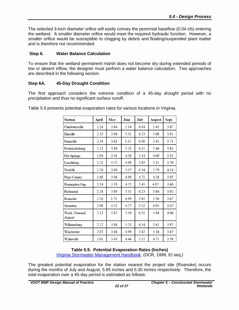
The selected 3-inch diameter orifice will easily convey the perennial baseflow (0.04 cfs) entering the wetland. A smaller diameter orifice would meet the required hydraulic function. However, a smaller orifice would be susceptible to clogging by debris and floating/suspended plant matter and is therefore not recommended. Step 6. Water Balance Calculation To ensure that the wetland permanent marsh does not become dry during extended periods of low or absent inflow, the designer must perform a water balance calculation. Two approaches are described in the following section. Step 6A. 45-Day Drought Condition The first approach considers the extreme condition of a 45-day drought period with no precipitation and thus no significant surface runoff. Table 5.9 presents potential evaporation rates for various locations in Virginia.
Table 5.9. Potential Evaporation Rates (Inches) Virginia Stormwater Management Handbook, (DCR, 1999, Et seq.)
The greatest potential evaporation for the station nearest the project site (Roanoke) occurs during the months of July and August, 5.85 inches and 5.30 inches respectively. Therefore, the total evaporation over a 45-day period is estimated as follows:

5.4 - Design Process
VDOT BMP Design Manual of Practice
23 of 27
Chapter 5 – Constructed Stormwater Wetlands
Average evaporation per month = ininin 58.52
30.585.5=
+
Average evaporation per day = dayin
monthdaymonth
in
18.031
58.5=
The evaporation loss over a 45-day period is calculated as follows.
ftindayinX 68.01.8.180 days 54 ==
The total surface area of the marsh is 20,499 ft2. Therefore, the total volume of water potentially lost to evaporation is estimated as:
32 939,1368.0499,20 ftftft =× The volume of water lost to evaporation must be added to that lost to infiltration. As previously stated, the initial geotechnical tests revealed site soil infiltration rates to be 0.02 inches per hour. The infiltration is assumed to occur over the entire marsh, whose surface area is 15,160 ft2. The volume of water lost to infiltration is estimated as:
32 898,36452412102.0499,20 ftdays
dayhr
inft
hrinft =××××
The total volume of water lost to evaporation and infiltration over the 45-day drought period is therefore computed as:
333 837,50898,36939,13 ftftft =+ This value exceeds the total marsh volume of 17,424 ft3, implying that a 45-day drought period will leave the marsh area in a completely dry state. Over time, it is quite likely that the infiltration rate of the basin soil will decrease considerably due to clogging of the soil pores. However, the aquatic and wetland plant species will likely not survive an extended period of drought that occurs prior to this clogging. Therefore, at this point in the design, it would be recommended to install a clay or synthetic basin liner as approved by the Materials Division. A typical infiltration rate for synthetic liner may be on the order of 3x10⁻⁷ in/sec. The calculation is repeated for this rate of infiltration.
372 993,14524sec600,3121
sec103499,20 ftdays
dayhr
hrinftinxft =××××× −
The recalculated volume of water lost to evaporation and infiltration over the 45 day drought period is therefore computed as:

5.4 - Design Process
VDOT BMP Design Manual of Practice
24 of 27
Chapter 5 – Constructed Stormwater Wetlands
333 932,15993,1939,13 ftftft =+ While the extended drought period does impact the marsh area significantly, a minimal volume of water is retained in the marsh. The volume of runoff necessary to replenish the depleted marsh volume is computed as follows: Total contributing drainage area = 17.4 acres Stored volume lost to evaporation and infiltration = 15,932 ft3
Inches -Watershed 0.24 Feet-Watershed
acftac
ft==
×02.0
560,434.17
932,152
3
A precipitation event yielding a total runoff of 0.24 inches or more across the contributing watershed will replenish the depleted marsh volume. Step 6B. Period of Greatest Evaporation (in Average Year) The second water balance calculation examines impacts on the marsh during the one-month period of greatest evaporation during an average year. This calculation reflects an anticipated marsh drawdown during the summer months. In contrast, the first calculation method reflects an extreme infrequent drought event. From Table 5.9, the greatest monthly evaporation total for the station nearest the project site is 5.85 inches in July. The Virginia State Climatology Office reports an average July rainfall for the Blacksburg station as 3.99 inches (reference Step 5 for link to data). Applying the previously computed runoff efficiency ratio for the basin watershed, the average July inflow to the basin is computed as:
32
286,98560,434.1712139.099.3 ft
acftac
inftinches =××××
Evaporation losses are computed as the product of total monthly evaporation and the surface area of the permanent pool:
32 993,9499,2012185.5 ftft
inftinches =××
Infiltration losses (with synthetic liner) over the entire month of July are estimated as:
372 373,13124sec600,3121
sec103499,20 ftdays
dayhr
hrinftinxft =××××× −
The water balance expression and total monthly loss/gains are computed as follows:
Monthly loss/gain = Inflow – Evaporation – Infiltration

5.4 - Design Process
VDOT BMP Design Manual of Practice
25 of 27
Chapter 5 – Constructed Stormwater Wetlands
3333 920,86373,1993,9286,98 ftftftft =−−= The monthly climate data and site land cover characteristics indicate that the wetland marsh will not experience drawdown during the average period of highest evaporation. Step 7. Landscaping Generally, the non-marsh regions of constructed stormwater wetlands (i.e. the semi wet zone) can be landscaped in much the same manner as a typical stormwater impounding facility. However, careful attention must be given to the types of vegetation selected for the wetland marsh areas. For these regions, the vegetative species must be selected based on their inundation tolerance and the anticipated frequency and depth of inundation. If appropriate vegetative species are selected, the entire marsh area should be colonized within three years. Because of this rapid colonization, only one-half of the total low and high marsh zone areas need to be seeded initially. A total of five to seven different emergent species should be planted in the wetland marsh areas. Both the high and low marsh areas should each be seeded with a minimum of two differing species. The regions of varying depth within the wetland are broadly categorized by zone as shown in Figure 5.8.
Figure 5.8. Planting Zones for Stormwater BMPs Virginia Stormwater Management Handbook (DCR, 1999, Et seq.)
Suitable planting species for each of the zones identified in Figure 5.9 are recommended in Chapter 3-05 of the Virginia Stormwater Management Handbook, (DCR, 1999, Et seq.). Ultimately, the choice of planting species should be largely based on the project site’s physiographic zone classification. Additionally, the selection of plant species should match the

5.4 - Design Process
VDOT BMP Design Manual of Practice
26 of 27
Chapter 5 – Constructed Stormwater Wetlands
native plant species as closely as possible. Surveying a project site’s native vegetation will reveal which plants have adapted to the prevailing hydrology, climate, soil, and other geographically-determined factors. Figure 3.05-4 of the Virginia Stormwater Management Handbook provides guidance in plant selection based on project location. Generally, stormwater management facilities should be permanently seeded within 7 days of attaining final grade. This seeding should comply with Minimum Standard 3.32, Permanent Seeding, of the Virginia Erosion and Sediment Control Handbook, (DCR, 1992, Et seq.). It must be noted, however, that permanent seeding is prohibited in Zones one through four of Figure 5.9. The use of conventional permanent seeding in these zones will result in the grasses competing with the requisite wetland emergent species. When erosion of basin soil prior to the establishment of mature stand of wetland vegetation is a concern, Temporary Seeding (Minimum Standard 3.31) of the Virginia Erosion and Sediment Control Handbook, (DCR, 1992, Et seq.) may be considered. However, the application rates specified should be reduced to as low as practically possible to minimize the threat of the Temporary Seeding species competing with the chosen emergent wetland species. All chosen plant species should conform to the American Standard for Nursery Stock, current issue, and be suited for USDA Plant Hardiness Zones 6 or 7, see Figure 5.9.
Figure 5.9. USDA Plant Hardiness Zones

5.4 - Design Process
VDOT BMP Design Manual of Practice
27 of 27
Chapter 5 – Constructed Stormwater Wetlands
If the wetland is equipped with an impounding embankment, under no circumstances should trees or shrubs be planted on the basin embankment. The large root structure may compromise the structural integrity of the embankment.