chapter 46 manual of construction specifications and
TRANSCRIPT

CHAPTER 46
Manual of
Construction Specifications and
Details for Roads, Open Space and Utilities
Town of Middletown

TABLE OF CONTENTS
Chapter 46-1 Streets
Chapter 46-2 Sanitary Sewer
Chapter 46-3 Water
Chapter 46-4 Open Space/Recreation
Supplemental Tracer Wire Specification
Chapter 46-5 Construction Details
Section D – Storm Drainage Details
D-1 Straight Headwall
D-2 Standard Headwall (48”, 54”, & 60” Pipe)
D-3 45° Standard Headwall (66” to 84” Pipe)
D-4 Straight Headwall (Horizontal Elliptical Concrete Pipe)
D-5 Straight Headwall (Metal Arch Pipe)
D-6 “L” Headwall
D-7 “L” Headwall (Metal Arch Pipe)
Section R – Road Details
R-1 Pavement Tie-In Section
R-2 Sidewalk
R-3 Residential Entrance (with Grass Strip)
R-4 Residential Entrance (without Grass Strip)
R-5 Residential Driveway Section (Concrete)
R-6 Residential Driveway Section (Asphalt)
R-7 Tmeporary Roadway Patch
R-8 Permanent Roadway Patch
R-9 Forestry Lane
Section S – Sanitary Sewer Details
S-1 Pipe Bedding & Trench Detail
S-2 Standard 48” Precast Concrete Manhole
S-3 Standard 60” Precast Concrete Manhole
S-4 Inside Drop Manhole Connection
S-5 Standard Manhole Frame and Cover
S-6 Sanitary Sewer Manhole Steps
S-7 Water Main Clearance
S-8 4” and 6” Drop House Connection (New Construction)
S-9 Typical Cannelization of Mainline Sewer Manholes
S-10 Concrete Encasement and Cradle
S-11 Concrete Encasement at Utility Crossings

S-12 Concrete Manhole Collar (Paved Areas)
S-13 Concrete Manhole Collar (Non-Paved Areas)
S-14 Manhole Frame Replacement
S-15 Riser Ring Detail
S-16 Typical Cleanout
S-17 Sewer House Connection (New Construction)
S-18 Standard House Connection (Existing Sewer Main)
Section W – Water Details
W-1 Standard Service Connection with Curb Box
W-2 Water Main Crossing Storm & Sanitary Sewer
W-3 Pipe Bedding & Trench Detail
W-4 Standard Fire Hydrant Installation
W-5 Thrust Blocks for Horizontal Bends
W-6 Thrust Blocks for Tees & Tapping Sleeves
W-7 Thrust Blocks for Plugs & Caps
W-8 Anchorage for 1/32, 1/16, & 1/8 Upper Vertical Bends
W-9 Thrust Blocks for 1/32, 1/16, & 1/8 Lower Vertical Bends
W-10 Standard Flushing Hydrant
W-11 Temporary Cap & Blow-off
W-12 Meter Pit Setter (1”, ½” & 2”)
W-13 Typical Detector Check Valve for Fire Service and ¾” to 2” Max.
Domestic Meter (In Pit)
W-14 Combined Compact Fire & Domestic Service Water Meter Assemblies
(Reduced Size Meter Pit)
W-15 Concrete Collar for Water Main Valves

CHAPTER 46-1
STREETS

46-1-2
INTENT
The intent of this article is to outline the requirements for the construction of streets within the
Town of Middletown. Unless specifically stated herewith, all materials, equipment, design,
details and construction methods associated with the construction of streets within the Town of
Middletown shall conform to the latest editions of the manuals, specifications and guidelines of
the Delaware Department of Transportation.
BITUMINOUS PAVEMENT
Description
A. The paving of all streets and entrances to driveways and parking areas within
the Town of Middletown right-of-way shall be constructed as shown on the final
approved plan and in accordance with the following standards.
Minimum Slope Requirements
A. The minimum lateral cross slope for all streets shall be 2.0% as measured from
the centerline of the street to the edge of pavement. The minimum longitudinal
slope, as measured along the centerline of the street, shall be 0.50%.
Soils Investigation Requirements
A. In the event the Town of Middletown determines a soil investigation is
necessary, a geotechnical engineer registered in the State of Delaware with
experience in pavement engineering shall perform the soils investigation. The
Developer shall be responsible for the cost of the soil investigation. Boring
locations, sampling procedures and method of testing shall be approved by the
Town of Middletown and in accordance with the latest procedures found in the
Delaware Department of Transportation Materials Manual. The Developer shall
be responsible for stabilizing all weak and wet sub-grade prior to construction of
the crushed aggregate base course.
B. If weak or wet areas are suspected or encountered during construction, the Town
of Middletown reserves the right to require a soils investigation as stated above,
or require additional borings and testing if a report was prepared prior to
construction. If the soils are found to be extremely weak with a soil resilient
modulus less than 3400 psi, the Town of Middletown reserves the right to require
an in-depth soils strength analysis and a specific pavement design that will
satisfactorily address the specific situation. The Developer shall be responsible
for all costs associated with the investigation and design.
C. In the event unsuitable soils are encountered during the installation of a utility
within the street right-of-way, the Town of Middletown reserves the right to
require the placement of backfill material meeting the most recent specifications
of the Delaware Department of Transportation. All costs associated with the
placement of backfill shall be the responsibility of the Developer.
D. In the event that streets are to be constructed in areas that require the removal of
unsuitable material, the Town of Middletown reserves the right to request an

46-1-3
investigation to determine the extent of the unsuitable material to be removed.
The Developer shall be responsible for all costs associated with the investigation.
Pavement Construction Material and Thickness Requirements
A. Pavements shall be designed based on the assumption of poor soil conditions.
All proposed streets shall be constructed, at a minimum, to the required type of
materials and thickness of layers as specified in the tables below. If any street is
expected to serve additional traffic in the future, such as an extension to a future
development or tie-in to another development, the anticipated future increase in
traffic shall be incorporated into the design.
B. For developments larger than 500 residential units or 2,000,000 square feet of
industrial/commercial building space, the Developer shall contact the Town of
Middletown for pavement design requirements necessary to meet the specific
situation.
Minimum Material Type and Layer Thickness Requirements
Residential Street: Up to 500 Units
Pavement Layer Thickness
Wearing (Surface) Course 2 in.
Binder Course 3 in.
Bit. Conc. Base Conc. 4 in.
Aggregate Subbase 9 in.
Structural Number 4.29
Geotextile Separator Optional
(To be determined by Town
of Middletown)

46-1-4
Commercial Street: Up to 2,000,000 Square Feet
Pavement Layer Thickness
Wearing (Surface) Course 2 in.
Binder Course 3 1/4 in.
Bit. Conc. Base Conc. 5 in.
Aggregate Subbase 12 in.
Structural Number 5.04
Geotextile Separator Optional
(To be determined by the
Town of Middletown)
Subgrade Verification Requirements
A. After the Developer has prepared the soil subgrade in accordance with the Town
of Middletown Street Construction Specifications, a proof roll of the prepared
subgrade shall be required prior to placing the geotextile separator (if required)
and asphalt base course. Density testing to verify compaction shall be performed
in the field as directed by the Town of Middletown. All costs associated with
compaction testing shall be paid by the Developer.
B. A proof roll of the prepared subgrade and crushed aggregate base course shall be
performed prior to the placing of the geotextile separator (if applicable) and
asphalt base course. The proof rolling shall consist of a triaxial dump truck fully
loaded to the maximum allowed weight (a certified delivery slip from the quarry
shall be required to verify the weight). The truck shall be required to run the
entire street subgrade including curb lines, over all trenches and anywhere
directed by the Town of Middletown inspector. Areas displaying movement,
pumping, pronounced elasticity or deformation under the loaded triaxial dump
truck will be considered unstable and will be noted and or marked. The areas
marked and or noted showing unstable subgrade shall be corrected and re-
verified for the required stability prior to placing the geotextile separator (if
applicable) and asphalt base course.
C. A Town of Middletown inspector shall perform an inspection to verify the grade
elevations of the subgrade and crushed aggregate base course prior to placement
of the geotextile separator (if applicable) and asphalt base course. Contractor
shall ensure that sufficient grade stakes are in place to allow for the appropriate
measurements. Any areas that are not at the proposed design grade shall be
corrected and re-inspected prior to placing the geotextile separator (if applicable)
and asphalt base course.
46-1-5
STREET SIGNS
Description
A. All signs, including regulatory, warning, directional and street signs shall be installed
in accordance with the final approved plans and in conformity with the requirements
of these Specifications and the Delaware Department of Transportation. In the event
field conditions create difficulty adhering to the approved plans or specifications, the
Developer shall install the signs in accordance with the direction provided by the
Town of Middletown.
All signs installed within the Town of Middletown shall meet the reflective
requirements of the Delaware Department of Transportation.
Sign Posts
A. All street name sign posts shall be 2 3/8” diameter hot dipped galvanized steel round
pipe. Sign posts for all other signs including regulatory, warning, parking and speed
limit signs shall be hot dipped galvanized square channel with 3/8” holes on 1”
centers in accordance with DelDOT standards.
B. The minimum distance from the final grade to the bottom of the sign shall be seven
(7) feet.
Street Name Signs (Blades)
A. Street name signs shall be ordered by the Developer.
B. Street name signs shall be steel plates stamped black on a white background. The
lettering shall be four (4) inches high on a background six (6) inches high. Compass
and street abbreviations shall be two (2) inches high.
C. Street name signs shall be manufactured by the Gopher Sign Company, 1310 Randolf
Avenue, St. Paul, MN 55105, or approved equal.
STOP Signs
A. STOP signs shall be an octagon, 30 x 30 inches, with a white message and border on
a red background.
LIGHTING
Description
A. The Town of Middletown Electric Department is responsible for coordinating the
street light design, purchasing all materials and installation. The Town of
Middletown is responsible for selecting the type of lights installed.
B. It shall be the responsibility of the Developer to pay the Town of Middletown for all
costs associated with the installation of street lights including design, material and
labor.

46-1-6
CURB AND GUTTER
Description
A. All streets dedicated to the Town of Middletown shall be constructed with Integral
P.C.C. Curb and Gutter, Type 3 in accordance with the standards and specifications
of the Delaware Department of Transportation. All other types of curb and gutter
shall only be permitted with written approval by the Town of Middletown.
DRAINAGE PIPE
Description
A. All drainage pipe installed within the dedicated Town of Middletown right-of-way
shall be Reinforced Concrete Pipe.
B. Video taped inspection of the completed storm drainage system shall conform to the
standards and specifications of the Delaware Department of Transportation.
C. Upon completion of all drainage, and prior to acceptance, as-built drawings shall be
submitted to the Town of Middletown for review and approval. One electronic copy
in .pdf format shall be submitted bearing the signature and seal of a Delaware
registered surveyor or engineer with the same scale as the original approved
drawings.
CATCH BASINS
Description
A. Catch basin submittals shall be submitted to the Town of Middletown for review and
approval for all structures that are not in conformance with the standard
specifications of the Delaware Department of Transportation.
B. A storm drain marker bearing the words “Don’t Pollute Flows to Waterways” as
manufactured by Das Manufacturing, or approved equal, shall be installed on all
catch basins prior to final acceptance. The Developer shall follow all manufacturers
specifications for the installation.
SPEED BUMPS
Description
A. Speed bumps shall be prohibited within all right-of-way dedicated to the Town of
Middletown.

CHAPTER 46-2
SANITARY SEWER

46-2-2
INTENT
The intent of this article is to outline the requirements for the construction of sanitary sewer
within the Town of Middletown. Unless specifically stated herewith, all materials, equipment,
design, details, testing and construction methods associated with the construction of sanitary
sewer within the Town of Middletown shall conform to the latest specifications and details of
New Castle County.
SANITARY SEWER GRAVITY MAINS AND HOUSE CONNECTIONS
Description
A. This section shall consist of gravity sanitary sewers mains and house connections
within the right-of-way or a Town maintained easement of ductile iron pipe
(DIP) or polyvinyl chloride (PVC) pipe of the diameter shown on the Plans, laid
on a firm bed true to line and grade in accordance with these Specifications and
Details. No other materials shall be allowed to be used for gravity sewer
installation without written approval by the Town of Middletown.
Materials
A. Polyvinyl Chloride (PVC) Pipe. PVC pipe, used for gravity sewer construction,
shall equal or exceed the requirements of ASTM D-3034 and shall have a
minimum Standard Dimension Ratio (SDR) of 26 and the minimum pipe
stiffness, as tested in accordance with ASTM D-2412, shall be 45 psi when
measured under 5 percent deflection at 73 degrees Fahrenheit. Pipe shall be
manufactured with integral wall bell and spigot joints in standard lengths not
exceeding twenty (20) feet.
Polyvinyl Chloride (PVC) pipe fittings shall utilize an elastomeric O-ring
gasketed joint assembly in accordance with the manufacturer’s
recommendations.
Polyvinyl Choride (PVC) Wye, T-Wye branches, pipe stoppers and other fittings
shall be manufactured in accordance with the same specifications and shall have
the same thickness, depth of socket, and annular space as the main pipe. Wye
and T-Wye branches shall be complete pipe sections.
Service saddles will not be permitted for use in new construction.
Polyvinyl Chloride (PVC) pipe shall be delivered and stockpiled in unit pallets.
No stacking of pallets above 5 feet in height will be allowed. If pipe is stockpiled
for more than 30 days prior to installation, it must be suitably covered with
reflective material to protect the pipe from ultra-violet rays emanating from
sunlight. Do not use plastic sheets. Allow for air circulation under covering.
Bowed sections of pipe will be unacceptable. Installation of pipe which has
bowed, whether or not the bow has been corrected, will not be allowed.

46-2-3
B. Ductile Iron (DIP) Pipe. DIP pipe shall be manufactured in accordance with
ANSI A21.51, latest edition, and shall be thickness Class 52 unless otherwise
approved by the Town. The contractor shall have the option of furnishing
mechanical or push-on joints conforming to ANSI A21.11, latest edition.
Pipe and fittings shall be double cement lined with seal coat and shall receive an
external standard bituminous foundry coating in accordance with ANSI A21.4
Gravity sewer mains installed at depths exceeding 18 feet shall be required to be
ductile iron pipe.
All fittings used to connect ductile iron sewer main pipe shall be ductile iron with
a 250 psi pressure rating and marked in accordance with ANSI A21.10.
C. Sanitary Sewer Lateral Cleanout Frames and Covers. Cleanout frames and
covers shall be cast iron. Cleanout frames and covers shall be water tight with
recessed lifting holes. Terminal sewer and house lateral cleanout frames and
covers shall be brass caps used with PVC pipe.
D. Detection Tape. Pipeline detectable tape shall be installed continuously along all
gravity sewers. The tape shall be installed directly above the gravity sewers and
24 inches below the ground surface. The tape shall be Lineguard Type III
Detectable Tape as manufactured by Lineguard, Inc., of Wheaton, Illinois, or
equal. The tape shall be a minimum of two inches wide, green in color,
imprinted with the words “Caution-Sewer Line Below”, and be capable of
being detected with inductive methods.
E. Concrete. All concrete for manhole base slabs and cradles, flow channels,
encasements, blocking, etc., shall have a minimum compressive strength of 3,000
psi at 28 days. Type II Portland Cement shall be used.
F. Sand. Sand shall be composed of sharp, angular, siliceous grains, coarse, or
graded from fine to coarse with the coarsest grains predominating, and sensibly
free from clay, loam, dirt, mica, organic matter, or other impurities.
Sand containing more than 5 percent by weight of foreign material shall not be
used. This limit may be changed for special classes of work if hereinafter
specified.
Sand exhibiting more than an acceptable amount of fine matter or impurities may
be required to be washed after delivery or shall be rejected altogether. The
Contractor shall submit samples of the sand he proposes using. These shall be
retained in the office of the Inspection Agency as a standard for comparison
during the progress of the work, and all sand used shall be equal in quality to the
acceptable samples. Sand for mortar shall be screened to reject all particles of a
greater diameter than 1/4 inch and shall not contain more than 5 percent by
weight of a very fine material.
G. Mortar. Cements shall be Class B Sulfur resistant in accordance with the
“Standard Specifications for Portland Cement,” ASTM Designation C 150 for

46-2-4
Type II.
Unless hereinafter specified otherwise, all mortar shall be composed of cement
and sand of the character specified above. The proportion by volume shall be
one part of cement to two parts of sand. One volume of cement shall be 94
pounds net. One volume of sand shall be 0.9 cubic feet, the sand not being
packed more closely than by throwing it into a box in the usual way. Mortar
shall be fresh mixed in small batches for the work in hand. Tight boxes or
platforms made for the purposes shall be used. The sand and cement shall be
thoroughly mixed dry, in the proper proportions, until a uniform color has been
produced, whereupon a moderate dose of water shall be added, so as to produce a
stiff paste of the proper consistency.
Sand obtained from the excavation shall not be used.
Construction Methods
A. Topsoil, vegetative matter, and other organic material shall be stripped from
areas that are to be disturbed by construction, and stockpiled. Topsoil shall be
segregated from non-organic trench excavation material and debris.
Trench backfill material shall be satisfactory soil excavated from the trench, or
imported soil meeting DelDOT specifications for trench backfill. Satisfactory
trench backfill shall be free from frozen matter, stumps, roots, brush, other
organic matter, cinders or other corrosive material, debris, and any rocks or stone
larger than 6 inches, in any dimension. Material that is excessively wet and or
unable to compact in a satisfactory manner will not be placed for backfill. The
Town of Middletown Inspection Department will direct the contractor to stop
installation and backfilling operations if proper compaction is not achieved.
B. Laying Pipe. Pipe shall be carefully handled and lowered into the trench. In
laying pipe, special care shall be taken to ensure that each length shall abut
against the next in such a manner that there shall be no shoulder or unevenness of
any kind along the inside of the bottom half of the pipe line. No wedging or
blocking will be permitted in laying any pipe unless by written order or
permission from the Town.
Before joints are made, each pipe shall be well bedded on a solid foundation, and
no pipe shall be brought into position until the preceding length has been
thoroughly embedded and secured in place with a minimum of 6 inches of
crushed angular stone, ¾ inch maximum size. The Contractor shall make any
defects due to settlement good. Bell holes shall be dug sufficiently large enough
to ensure that the pipe is firmly bedded on the full length of the barrel.
Proper and suitable tools and appliances for the safe and convenient handling and
laying of pipes shall be used.
The pipes shall be thoroughly cleaned before they are laid and shall be kept clean
until the acceptance of the completed work. The open ends of all pipelines shall
be provided with a stopper carefully fitted, so as to keep dirt and other substances
from entering. This stopper shall be kept in the end of the pipe line at all times

46-2-5
when not in the process on laying pipe.
Whenever a pipe requires cutting to fit into the line or to bring it to the required
location, the work shall be done in a satisfactory manner so as to leave a smooth
end, without extra compensation.
All concrete required to support and reinforce Wye branches and bends shall be
placed as shown in the Standard Details or as directed by the Town.
All sewer house connections shall be laid on a two (2) percent grade unless
otherwise directed. All house connections shall meet the requirements of the
Town of Middletown’s adopted Plumbing Code unless otherwise directed by the
Town.
All sewer house connections shall be constructed to terminate at an angle
perpendicular to the property lines unless otherwise noted on the plans.
The excavation in which pipe is being laid shall be kept free from water and no
joint shall be made under water. Water shall not be allowed to rise in the
excavation until pipe bedding and backfill has been completed. The greatest care
shall be used to secure water tightness and to prevent damage to, or disturbing of,
the joints during the backfilling process, or at any time. After pipes have been
laid and the joints have been made, there shall be no walking on or working over
them except such as may be necessary in tamping, until there is a covering at
least two feet in depth, over their top.
All pipe shall be placed in accordance with the installation recommendations of
the pipe manufacturer and applicable portions of this Specification.
No pipe shall be laid upon a foundation into which frost has penetrated at any
time such that there is danger of the formation of ice or the penetration of frost at
the bottom of the excavation, unless the minimum length of open trench and
promptness of refilling are observed.
Branches shall be located in a position designated by the Developer’s Engineer or
his representative. Short pieces of lateral sewer shall be field-cut to meet this
condition. The Contractor shall have on the work site, at all times, factory
approved equipment to machine and adapt the field-cut end of short pieces to
standard couplings and jointing materials.
Minimum depth of cover for any sewer main shall be 42 inches measured from
the top of the pipe to the final grade above the pipe.
C. Backfill and Compaction. All trench backfill shall be compacted. Backfill of
pipe and manholes shall be compacted with equipment in a manner which is
capable of producing the required results. Backfill material shall be placed and
graded in uniform horizontal lifts, which may not exceed 8 inches. Compaction
will not be performed by jetting or water settling. If during the compaction of the
trench, any soft, yielding, or spongy areas are observed, backfilling operations
will cease until stability of these areas is achieved. The Town of Middletown has

46-2-6
the authority to request field moisture/density control tests to document
compliance of work as per DelDOT’s specifications. Failed areas shall be
compacted again and retested. A Geotechnical Consultant approved by the Town
of Middletown shall perform moisture/density tests at the Developer’s expense.
D. Connection to Existing Manholes. Connection to existing manholes shall be
made at such points and of such form, dimensions and elevations as indicated on
the Plans or as the Town of Middletown shall require.
The size of the opening through the wall of the existing manhole for the pipeline
connections shall not exceed the outside diameter of the pipe plus 6 inches. All
connections shall be fully grouted by using a non-shrinking grout. Manhole
adapters shall be used on all connections to existing manholes.
Care shall be taken by the Contractor to prevent broken brick and mortar from
entering the existing or proposed pipes. A screen shall be provided below the
area of work to catch any falling debris.
Core drilling is the only acceptable method of making a new opening in an
existing reinforced concrete manhole.
Alignment
A. Sanitary sewers shall be installed with straight horizontal and vertical alignments
between manholes. When a smaller sewer joins a larger one, the invert of the
larger sewer should be lower to allow the crowns of both pipes to be at the same
elevation. The invert of a pipe exiting a manhole shall be lowered the
appropriate distance compared to the invert of the pipe(s) entering the manhole to
account for the head loss within the manhole.
Storm Drain Separation
A. Sanitary sewers shall be laid at least 3 feet horizontally from any storm drain pipe
measured edge to edge. Sanitary sewer mains that cross a drainage pipe shall be
encased in concrete, a minimum of five (5) feet on either side of the centerline of
the crossing, if there is less than two (2) feet of clearance between the outside
diameter of the sanitary sewer and the outside diameter of the drainage pipe. A
full length of sanitary sewer pipe shall be installed centered on the storm drain to
maximize the distance to a sanitary sewer pipe joint.
Horizontal and Vertical Separation.
A. In general, horizontal and vertical separation shall be per 10 States Standards.
Sewer mains shall be laid at least ten (10) feet horizontally from any existing or
proposed water main. The distance shall be measured edge to edge. Separation
between sewer and water laterals shall be a minimum of three (3) feet measured
inside edge to inside edge, or as required in the adopted plumbing code,
whichever is stricter.
B. Sewers crossing water mains shall be laid to provide a minimum vertical distance
of eighteen (18) inches between the outside of the water main and the outside of

46-2-7
the sewer.
a. Sewer lines shall be located below water mains unless otherwise
authorized by the Town.
b. When a sewer main crosses an existing water main, the crossing shall be
arranged so that the sewer joints will be equidistant and as far as
possible from the water main joints.
c. Where a water main crosses under a sewer, adequate structural support
shall be provided for the sewer to maintain line and grade and prevent
damage to the water main.
d. When it is impossible to obtain proper horizontal and vertical
separations stipulated above, the Town may allow deviations on a case-
by-case basis, if supported by data from the Design Engineer. Alternate
design shall meet 10 State Standards.
Acceptance Testing
A. Prior to the request for final acceptance by the Town, it shall be the Contractor’s
responsibility to examine all completed pipe lines to insure that they are laid to
the proper alignment and grade and free from foreign material. After this has
been done to the satisfaction of the Town, the Town will order tests to be made
on all portions of the sewers built under the Contract. The Contractor shall
cooperate and furnish all assistance necessary to perform the tests as specified
herein and as directed by, and under the direction of the Town’s inspector.
1. Deflection Testing of Sanitary Sewers – Sanitary sewers shall be tested in the
presence of the Town’s inspector and the Contractor’s representatives to
determine the amount of vertical deflection in the completed pipe line as
follows:
Deflection testing as specified hereinafter shall be accomplished by the
Contractor on all sanitary sewers installed. Should significant failures be
detected, additional deflection testing shall be performed by the Contractor.
Installation of sanitary sewers shall be complete prior to the start of
deflection testing. All sheeting shall be removed except where written
approval from the Town to keep the sheeting has been obtained. All backfill
shall be placed to finished grade and dewatering operations ceased.
A mandrel with a diameter equivalent to 95 percent of the inside diameter of
the pipe to be tested shall be pulled through the pipeline, from manhole to
manhole, by hand. If the steel ball is unable to pass through the pipe without
applying excessive force (as judged by the Town), it will be constructed as
evidence that the pipe has deflected more than 5 percent of the inside pipe
diameter. A permanent record of all testing with locations where excessive
pipeline deflections occur shall be kept by the Contractor and forwarded to
the Inspection Agency after completion of testing on each line. The mandrel
shall be approved by the Inspection Agency prior to use. Mandrels shall
have an odd number of gauging plates. The minimum number of plates shall
be nine (9) with a contact surface length equal to the inside pipe diameter
plus two (2) inches for pipelines 10 inches in diameter and smaller. On
46-2-8
larger diameters, the contact surface length shall equal the inside pipe
diameter.
The Contractor shall immediately replace all sections of pipe which deflect
more than 5 percent.
2. Air Acceptance Test – The Town of Middletown reserves the right to utilize
a low pressure air acceptance test for pipe with a diameter of 39 inches or
less. The Contractor shall furnish all equipment and personnel to conduct
this test in accordance with the following procedure:
a. All branch fittings and ends of lateral stubs shall be securely
plugged to withstand the internal test pressures. The section of line
being tested shall also be securely plugged at each manhole. All
stoppers shall be adequately braced when required.
b. Air shall be slowly supplied to the plugged pipe line until the
internal air pressure reaches 5.0 pounds per square inch greater than
the average back pressure of any ground water that may submerge
the pipe. This pressure shall remain for a minimum of six (6)
minutes with no drop in pressure.
The Contractor shall be responsible to repair all defects in the event the pipe
is unable to maintain pressure.
The Contractor shall not make any connections to the existing sanitary
sewers until after the acceptance tests have been performed and approved by
the Town.
3. Camera Inspection
The Town of Middletown reserves the right to require a TV inspection of
sewer mains and laterals. This inspection will take place as a final punch list
item and before top lift of hot-mix is placed.
Inspection shall be performed by a NASSCO Pipeline Assessment
Certification Program (PACP) certified operator and shall meet the coding
and reporting standards and guidelines as set by PACP. These same
standards shall also be used for lateral inspections regardless of whether
conducted using cleanout launched or mainline launched lateral camera. All
report annotations, pipe conditions and pipe defects shall be identified
properly using PACP codes as defined by PACP, and severity ratings shall be
calculated according to PACP.
Quality of inspection recording shall be acceptable to the Town when viewed
on a standard computer monitor.
Submittal of PACP certificate to Town of Middletown inspectors completing
the work shall be required.

46-2-9
Closed Circuit TV Equipment: Select and use closed-circuit television
equipment that will produce a color recording.
Pipe Inspection Camera: Produce video recording using a pan-and-tilt, radial
viewing, pipe inspection camera that pans ± 275 degrees and rotates 360
degrees. Use a camera with an accurate footage counter that displays on the
TV monitor the exact distance of the camera from the centerline of the
starting manhole. Use a camera with camera height adjustment so that the
camera lens is always centered at one-half the inside diameter, or higher, in
the pipe being televised. Provide a lighting system that allows the features
and condition of the pipe to be clearly seen. A reflector in front of the
camera may be required to enhance lighting in large diameter pipe. Lighting
shall not cause shadows within the field of view of the camera, either when
forward viewing or when using pan/tilt. The camera, television monitor and
other components of the video system shall be capable of producing a
minimum 500-line resolution colored video picture. Picture quality and
definition shall be to the satisfaction of the Town.
Mainline Launched Lateral Inspection Camera: Produce a video recording
using a fixed orientation color camera capable of extending into open laterals
for a minimum distance of 80 feet from the lateral connection. Minimum
performance standards are as noted above in Pipe Inspection Camera.
Lateral Cleanout Launched Lateral Inspection Camera: Alternatively,
Contractor may produce a video recording of the sewer lateral between the
sewer lateral cleanout and the mainline using a mini-cam launched from the
sewer lateral cleanout. Minimum performance standards are as noted above
in Pipe Inspection Camera.
TV Studio: TV studio is to be contained in an enclosed truck, trailer or van.
It shall have room and seating for the operator and the Town and also room
for at least one standing visitor with the doors closed. The studio shall have
air conditioning and heating. Normal operation of all equipment, including
the TV camera, monitor, and winches is to be from a control panel in the
studio. When joint testing and sealing is to be performed, the equipment
shall be contained in the same unit as its TV equipment and shall be operated
from the same control panel.
Recording: All recordings are to be in digital format.
1. Image Capture – Digitized picture images shall be stored and be
exportable as JPEG formats. Minimum resolution shall be 1024 x
768.
2. Video Capture – Full time live video and audio files shall be
captured for each pipe segment and lateral inspected. The files shall
be stored in industry standard MPEG format viewable from a DVD.
The MPEG video shall be ISO-MPEG Level 1 (MPEG-1) coding
with a resolution of 352 pixels (x) by 240 pixels (y) and an encoded
frame rate of 29.97 frames per second. System shall perform an
automatic disk image/file naming structure to allow saved video/data

46-2-10
sections to be “burned” to digital format. It shall have the capability
of “burning” a minimum of 120 minutes of recording to digital
media. The video recording shall be free of electrical interference
and shall produce a clear and stable image. The audio recording
shall be sufficiently free of background and electrical noise as to
produce an oral report that is clear and discernable. The digital
recordings and inspection data shall be cross-referenced to allow
instant access to any point of interest within the digital recording.
Television Inspection: Additional requirements.
a. Sewer lines and manholes are required to be clean. Prior to the
television inspection, any sewer line or manhole found to be dirty
during the TV inspection process will be cleaned by the Contractor.
b. Televise the sewer line to document the condition of the line.
Provide a color recording showing the completed work.
c. For mainline inspections, inspections shall be from center of the
starting manhole to the center of the ending manhole. Distances
along the pipe should be measured from the center of the upstream
manhole.
The Contractor shall be responsible to repair all defects observed in the
camera and television inspection prior to final acceptance by the Town of
Middletown.
As-Built Drawings
A. Upon completion of all sanitary sewer, and prior to acceptance, as-built drawings
shall be submitted to the Town of Middletown for review and approval. One
electronic copy in .pdf format shall be submitted bearing the signature and seal of
a Delaware registered surveyor or engineer with the same scale as the original
approved drawings.
Minimum Size
A. No sewer main shall be less than eight (8) inches in diameter. The minimum size
of a sewer lateral shall be six (6) inches. Apartments/condominiums up to four
(4) units per cluster may use a six (6) inch diameter sewer lateral. Clusters with
more than four (4) units shall use a lateral size based on a computation of the
flow to be generated from the cluster.
Minimum Slope
A. All sewers shall be designed and constructed to provide mean velocities, when
full, of not less than two (2.0) feet per second. Based on Kutter’s formula or
Manning’s formula, an “n” value of 0.013 is generally used. Use of other
practical “n” values may be permitted if the available research or field data show
46-2-11
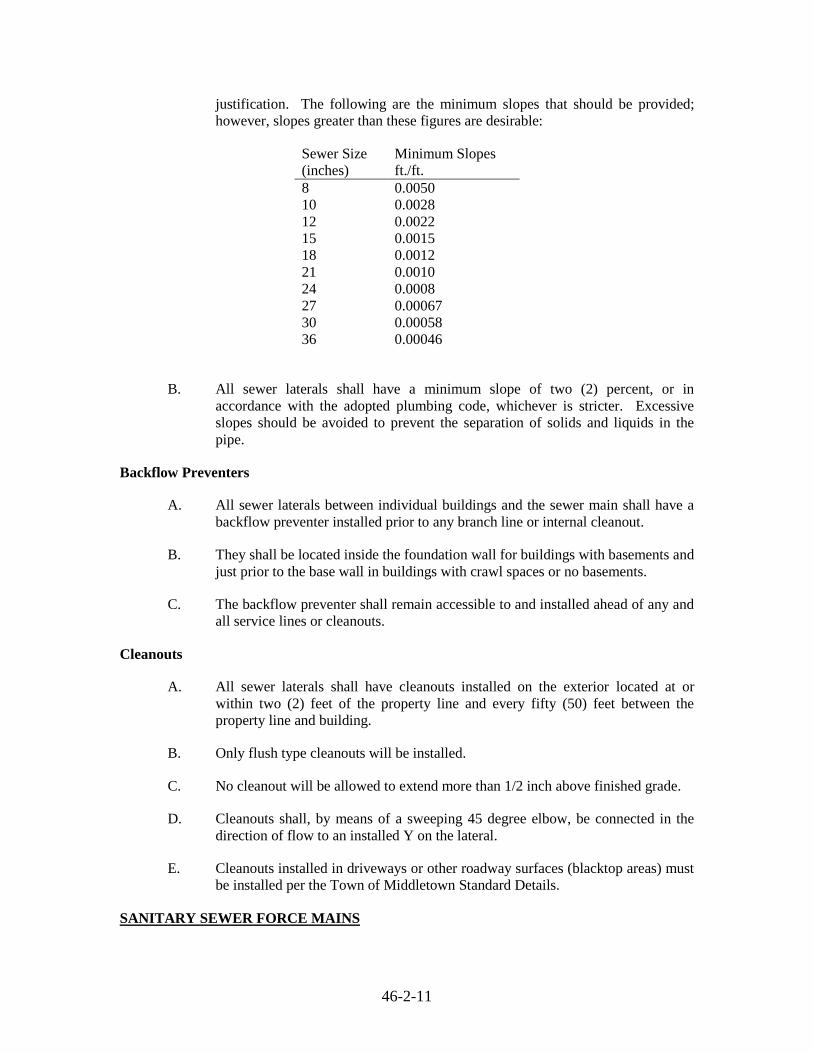
justification. The following are the minimum slopes that should be provided;
however, slopes greater than these figures are desirable:
Sewer Size
(inches)
Minimum Slopes
ft./ft.
8 0.0050
10 0.0028
12 0.0022
15 0.0015
18 0.0012
21 0.0010
24 0.0008
27 0.00067
30 0.00058
36 0.00046
B. All sewer laterals shall have a minimum slope of two (2) percent, or in
accordance with the adopted plumbing code, whichever is stricter. Excessive
slopes should be avoided to prevent the separation of solids and liquids in the
pipe.
Backflow Preventers
A. All sewer laterals between individual buildings and the sewer main shall have a
backflow preventer installed prior to any branch line or internal cleanout.
B. They shall be located inside the foundation wall for buildings with basements and
just prior to the base wall in buildings with crawl spaces or no basements.
C. The backflow preventer shall remain accessible to and installed ahead of any and
all service lines or cleanouts.
Cleanouts
A. All sewer laterals shall have cleanouts installed on the exterior located at or
within two (2) feet of the property line and every fifty (50) feet between the
property line and building.
B. Only flush type cleanouts will be installed.
C. No cleanout will be allowed to extend more than 1/2 inch above finished grade.
D. Cleanouts shall, by means of a sweeping 45 degree elbow, be connected in the
direction of flow to an installed Y on the lateral.
E. Cleanouts installed in driveways or other roadway surfaces (blacktop areas) must
be installed per the Town of Middletown Standard Details.
SANITARY SEWER FORCE MAINS

46-2-12
Description.
A. This section shall consist of sanitary sewer force mains within the right-of-way or
a Town maintained easement of ductile iron pipe (DIP), polyvinyl chloride
(PVC) pipe or of high density polyethylene (HDPE) of the diameter shown on
the Plans, laid on a firm bed true to line and grade in accordance with these
Specifications and Details.
B. Force mains shall be installed at the elevations indicated on the construction
drawings. Force mains shall maintain a minimum of 42 inches of cover.
Materials
A. Polyvinyl Chloride (PVC) Pressure Pipe. All buried PVC pressure pipe shall be
polyvinyl chloride pipe (PVC) Class 150 SDR-18 meeting the requirements of
ASTM D-2241. Fittings shall be in accordance with ASTM D-2466 of the same
color and pressure rating. Joints at the fittings shall be of the solvent weld type,
utilizing solvent meeting the intent of ASTM D-2564. At the remaining joints
push-on type joints with concrete buttresses may be used in accordance with
ASTM 3139. The elastomer seals used for joining the pipe shall meet ASTM
F477 Specifications. Lubricant shall be as recommended and supplied by the pipe
manufacturer.
Provide a joint restrainer for the connection to ductile iron pipe if thrust forces
present dictate this requirement. Provide a joint restrainer at all locations where a
transition to HDPE pipe is required. The restrainer shall provide a full 360-
degree contact with a serrated inside surface to secure the clamp to the pipe. The
restrainer shall be UNI-FLANGE Series 1300 or an approved equal for PVC to
ductile iron transitions. The restrainer between PVC and HDPE pipe shall be per
the recommendations of the HDPE pipe manufacturer.
B. Ductile Iron (DIP) Pipe. All buried ductile iron piping shall be Pressure Class 52
ductile iron meeting the requirements of AWWA Cl51. The Pipe shall be double
cement lined per AWWA C104 and have an internal coating system. The
internal coating shall be a ceramic epoxy and shall be an amine cured novalac
epoxy containing at least 20% by volume of ceramic quartz pigment. The
coating shall be US Pipe and Foundry Protecto 401 or an approved equal. Pipe
intended for buried installation shall receive an external standard bituminous
foundry coating in accordance with ANSI A21.4. All buried ductile iron pipe
shall have mechanical joints in accordance with AWWA C111.
a. All fittings shall be ductile iron compatible fittings with mechanical
joints meeting the requirements of AWWA Cl53. All fittings shall be
double cement lined per AWWA Cl04 and coated on the exterior with an
asphaltic coating. The interior coating shall be the same as for the pipe,
as noted above.
b. Provide restrained joints for all buried ductile iron pipe. Joints shall be
suitable for use with AWWA C111 mechanical joints. The follower
gland shall include a restraining mechanism which, when actuated,
imparts multiple wedging action against the pipe, increasing its
resistance as the pressure increases. Flexibility of the joint shall be
46-2-13
maintained after burial. Glands shall be manufactured of ductile iron
conforming to ASTM A536-80. Restraining devices shall be of ductile
iron heat treated to a minimum hardness of 370 BHN. Dimensions of tie
gland shall be such that it can be used with standard mechanical joint
with tee bolts. Twist-off nuts, sized same as tee-head bolts, shall be used
to insure proper torque and actuating of restraining devices. The
mechanical joint restraining device shall have a working pressure of at
least 250 psi with a minimum safety factor of 2, and shall be EBAA Iron,
Inc. MEGALUG, Mueller Aqua Grip, or approved equal.
C. High Density Polyethylene (HDPE) Pipe. HDPE pipe used for force main
construction, shall be PE3408 high density polyethylene meeting cell
classification 345444C or 345444E per the requirements of ASTM D-3350 and
shall be listed in the name of the pipe and fitting manufacturer in the Plastics
Pipe Institute TR-4, Recommended Hydrostatic Strengths and Design Stresses
for Thermoplastic Pipe and Fittings Compounds, with a standard HDB rating of
1600 psi at 73o F. Pipe and fittings shall be from the same manufacturer. Pipe
shall be manufactured in accordance with ASTM F714 or ASTM D 3035 and
shall be so marked. The pipe shall have a Standard Dimension Ratio (SDR)
suitable for the design operating condition means of installation and depth of
burial, as approved by the Town Engineer. HDPE force mains installed via the
directional bore method shall be SDR 11.0, minimum.
Pipe Detection
A. Force mains shall have tracer wire and detectable tape installed continuously
along its length. Detectable tape shall be installed in accordance with the
specifications outlined in the section entitled “Sanitary Sewer Gravity Mains and
House Connections”. Tracer wire shall be installed in accordance with the Town
of Middletown “Supplemental Tracer Wire Specification.”
Thrust Blocks.
A. Thrust blocks shall be provided on all force main plugs, caps, tees, and bends
deflecting 22-1/2 degrees or more either vertically or horizontally.
1. Thrust blocks shall be concrete with a compressive strength of 3000 psi
in 28 days.
2. Thrust blocking shall be located between solid ground and the fitting to
be anchored.
a. Unless otherwise shown or directed by the Town, place the base
and thrust bearing sides of thrust blocking directly against
undisturbed earth.
b. Place thrust blocking so the fitting joints will be accessible for
repair.
c. Protect steel rods and clamps by galvanizing or by coating with
bituminous paint.

46-2-14
Valves
A. Plug valves for force main isolation service shall be the non-lubricated type
designed for a minimum working pressure of 175 psi and suitable for buried
service. The valve shall be suitable for tight closure with pressure on either side
of the plug. Buried valves shall have mechanical joint ends. Valves installed in
vaults shall have flanged ends unless otherwise noted. The body shall be semi-
steel. The plug shall be semi-steel, resilient type neoprene faced for use in raw
sewage service. The plug seat shall have an overlay of mechanical nickel, fusion-
bonded Nylon II, or other suitable material on all surfaces in contact with the
plug face. The port area of the valve shall not be less than 100% of the pipe area.
The upper trunnion shall be sealed with either permanent “O”-ring type seals, or
packing held in place by an adjustable packing gland. Packing shall be
replaceable without disassembly of operator or valve. The upper and lower
journals shall be fitted with replaceable permanently lubricated stainless steel
sleeve type bearings. Valves shall be either hand wheel or 2-inch square nut
operated as indicated on the Plans. Plug valves shall be manufactured by the
DeZurik Unit of General Signal Corp. or an approved equal.
B. All plug valves shall be furnished with buried service type gear operators. Buried
valves shall be furnished with a roadway valve box and an extension stem
securely fastened to the operator to position a 2-inch square operating nut welded
to the top of the stem within 12 inches of the ground surface. An open and closed
indicator shall be provided on all valves at the operating nut. Valves shall open
left (counterclockwise). Spacer discs or rods shall be installed in the valve box as
required to center the extension stem. Extension stem shall be of the size
recommended by the valve manufacturer.
C. The exterior of the valve, operator, and extension stem shall be bituminous
coated unless otherwise noted.
Valve Boxes
A. Valve Boxes shall be cast iron, 3 piece screw type installed over the valve bonnet
and operating nut. Valve boxes shall be capable of being adjusted to reach the
surface of the existing or proposed grade but not to extend above the finished
grade at any time. Valve boxes shall be manufactured by Mueller or approved
equal.
Couplings and Wall Seals
A. Couplings shall be provided where required to facilitate the installation or
removal of valves and equipment, in addition to the couplings shown on the
drawings. All couplings shall be designed for the same pressure rating as of the
pipes on which installed. In addition:
B. The pipe couplings shall be of gasketed, sleeve-type, with diameter to properly fit
the pipe. Each coupling shall consist of one (1) steel middle ring 0.154 inches
thick and 5 inches in length, two (2) steel followers, two (2) rubber-compounded
wedge section gaskets and sufficient track-head steel bolts to properly compress
the gaskets. Field joints shall be made with this type of coupling.

46-2-15
C. The middle ring and followers of the coupling shall be true circular sections free
from irregularities, flat spots, or surface defects. They shall be formed from mill
sections with the follower-ring section of such design as to provide confinement
of the gasket. After welding, they shall be tested by cold expanding a minimum
of 1% beyond the yield point.
D. The coupling bolts shall be of the elliptic-neck track head design with rolled
threads. The manufacturer shall supply information as to the recommended
torque to which the bolts shall be tightened. All bolt holes in the followers shall
be oval.
E. The gaskets of the coupling shall be composed of a crude or synthetic rubber
base compounded with other products to produce material, which will not
deteriorate from age, from heat, or exposure to air under normal storage
conditions. It shall also possess the quality of resilience and ability to resist cold
flow so that the joint will remain sealed and tight when subjected to shock,
vibration, pulsation and temperature or other adjustments of the pipeline.
F. The couplings shall be assembled on the job in a manner to insure tight joints
under all reasonable conditions of expansion, contraction, shifting and settlement,
unavoidable variations in trench gradient, etc. The coupling shall be Dresser,
Style 38, as manufactured by Dresser Manufacturing Division, Bradford, Penna.,
or approved equal.
G. Wall seals shall be provided at all penetrations in concrete structures. In addition:
1. The Contractor shall determine the required inside diameter of each
individual wall opening or sleeve before ordering, fabricating or
installing. The inside diameter of each wall opening shall be sized as
recommended by the manufactured to fit the pipe and seal to assure a
water-tight joint.
2. Seals shall be Link-Seal, as manufactured by Thunder line Corporation,
or approved equal.
Acceptance Testing
A. Prior to acceptance, all new pressure pipes shall be tested as specified herein.
The contractor shall be responsible for furnishing all labor, tools, equipment,
materials, including water, pumps, compressors, pressure gauges, meters, and
stopwatch subject to the approval of the Town.
B. Any defective work, which shows up while conducting tests or before
acceptance, shall be replaced or repaired by the Developer at his own cost and
expense. Any leaks due to either blown joints or cracked pipe or fittings, shall be
repaired by the Developer at his own expense
C. All new force mains shall undergo a hydrostatic pressure test prior to acceptance
by the Town of Middletown.
D. Test Restrictions:

46-2-16
1. All tests shall be conducted in the presence of a Town Inspector.
2. Testing of all pressure pipes shall be conducted in accordance with
AWWA C600 testing requirements.
3. Test pressure shall be 150 psi.
4. The hydrostatic pressure test shall be of at least a 2-hour duration.
5. Valves shall not be operated in either direction at a differential pressure
exceeding the rated valve working pressure. The test pressure shall not
exceed the rated pressure of the valves when the pressure boundary of
the test section includes closed, resilient-seated gate valves or butterfly
valves.
E. Pressurization
1. After the pipe has been laid, all newly laid pipe or any valved section
thereof, shall be subjected to a hydrostatic pressure of 150 psi. Each
valved section of pipe shall be slowly filled with water, and the specified
test pressure (based on the elevation of the highest point of the line or
section under test and corrected to the elevation of the test gauge) shall
be applied by means of a pump connected to the pipe. Valves shall not
be operated in either the opening or closing direction at differential
pressures above the rated pressure. It is good practice to allow the
system to stabilize at the test pressure before conducting the test.
2. Before applying the specified test pressure, air shall be expelled
completely from the section of piping under test. If permanent air vents
are not located at all high points, corporation cocks shall be installed at
such points so that the air can be expelled as the line is filled with water.
After all the air has been expelled, the corporation cocks shall be closed
and the test pressure applied. At the conclusion of the pressure test, the
corporation cocks shall be removed and plugged or left in place as
directed by the Town.
3. All exposed pipe, fittings, valves, and joints shall be examined carefully
during the test. Any damage or defective pipe, fittings, valves, or joints
that are discovered following the pressure test shall be repaired or
replaced with sound material, and the test shall be repeated until
satisfactory results are obtained.
F. No drop in pressure will be allowed for the minimum two (2) hour duration. The
Contractor shall be responsible to repair all defects in the event the pipe is unable
to maintain pressure.
Construction Methods
A. The construction methods for sanitary sewer force mains shall be as described in
the specifications outlined in the section entitled “Sanitary Sewer Gravity Mains
and House Connections”.
Alignment/Separation
A. The alignment and separation requirements for sanitary sewer force mains shall
be as described in the specifications outlined in the section entitled “Sanitary

46-2-17
Sewer Gravity Mains and House Connections”.
As-Builts Drawings
A. Upon completion of all sanitary sewer force mains, and prior to acceptance, as-
built drawings shall be submitted to the Town of Middletown for review and
approval. One electronic copy in .pdf format shall be submitted bearing the
signature and seal of a Delaware registered surveyor or engineer with the same
scale as the original approved drawings.
SANITARY SEWER MANHOLES AND MISCELLANEOUS STUCTURES
Description
A. The work described in this section involves sanitary sewer manholes and
miscellaneous structures of concrete or brick masonry built to the shapes and
dimensions in accordance with these Specifications and Details as shown in the
Standard Details, at the location indicated on the Plans or as directed by the
Town.
Material
A. Precast Manholes. Precast reinforced concrete risers, eccentric cones and bases
shall be as detailed on the drawings and in conformance with ASTM Designation
C 478. Joints between riser sections shall be fitted with an “O” ring rubber
gasket, meeting the requirements of ASTM Designation C 443.
All pipe-to manhole connections shall be made by means of an integrally cast
flexible connector which shall be Lock joint flexible manhole sleeve as
manufactured by Interpace Corp., Parsippany, New Jersey, or A-Lok flexible
manhole gasket as manufactured by A—Lok Corp., Trenton, New Jersey, or
approved equal.
B. Manhole Steps. Manhole steps shall be made of 3/8-inch diameter (No. 3) steel
reinforcing bars, ASTM Designation A 615, Grade 60, encased in polypropylene
plastic. Manhole steps shall have notched tread ridge with retainer lug on each
side. Steps shall be spaced vertically and aligned as shown on the Standard Detail
Drawing and set to provide a minimum of 6-inch tread. Manhole steps shall be
OSHA approved and as manufactured by M.A. Industries, Inc., Peachtree City,
Georgia, ICM Inc., Jacksonville, Arkansas, or equal.
C. Manhole Frames and Covers. Manhole frames and covers shall be furnished and
set by the Contractor as the work progresses as shown in the Standard Detail
Drawing. Frames shall be well bedded in a concrete collar. Material for frames
and covers shall be in accordance with the Standard Specifications for gray iron
castings ASTM Designation A 48 for Class No. 35. The manhole frame and
cover shall be as shown in the Standard Details, or approved equal.
1. The cover shall have written on it “Town of Middletown
Sanitary Sewer.”
2. The manhole frame and cover shall be as shown in the Standard

46-2-18
Detail Section.
D. The flow pipe channel through manholes shall be made to conform in shape and
slope to that of the sewers. The top of the brick channel shall be at the same
elevation as the crown of the main sewer line in the manhole. The channel shall
drop a minimum of 1 inch from influent pipe to the effluent pipe.
E. All concrete for manhole base slabs and cradles, flow channels, encasements,
blocking, etc. shall have a minimum compressive strength of 3,000 psi at 28
days. Type II Portland Cement shall be used. All mortar and cement shall be
non-shrink.
F. All new laterals tying into existing concrete manholes shall require the manhole
to be core drilled for the connection. The lateral shall be installed and a
watertight seal accomplished with the use of Link Seal wall seals, or approved
equal.
Construction Methods
A. Precast Manholes – Precast reinforced concrete base and riser sections shall be as
manufactured by Atlantic Concrete Products Company, Virginia Precast
Corporation, or approved equal.
B. Manholes installed within the sewer distribution system shall conform to the
requirements of New Castle County or Town of Middletown, whichever is
greater, Type A-2 or A-3 precast manhole specifications.
C. In addition to the gasket material used within the joints between sections of the
manhole, an external joint wrap is required. The wrap is to be applied to a
clean/dry surface and placed with the manhole joint centered within the
membrane strip with a minimum overlap distance of eighteen (18) inches when
wrapped around manhole. Wrap shall be a self-adhered membrane consisting of
two waterproofing materials with an aggressive rubberized asphalt adhesive
backed by a layer of high density cross laminated polyethylene or approved
equal. The membrane strips shall be a minimum of twelve (12) inches wide.
D. Lifting holes in the walls of precast reinforced concrete risers will be allowed but
shall be plugged with rubber stoppers and grouted flush with face or manhole
wall after installation of manhole riser sections. Not more than two holes shall
be cast in the walls of each riser section for the purpose of handling.
E. The exterior surface of all precast manholes shall receive a minimum two coat
application of a 68 percent solids coal tar type protective coating. The total
average dry film thickness shall measure 24 mils with no single measurement to
be less than 20 mils. Surfaces shall be prepared in accordance with the
manufacturer’s instructions and coatings applied in the field in a manner
acceptable to the Town. The coating material shall be Bitumastic Super Service
Black manufactured by Koppers Co., Inc., Pittsburgh, Pennsylvania, Tar-Jet
Super Black XX-32-B-22 manufactured by Pennsbury Coatings Corp., New
Britain, Pennsylvania, or approved equal.

46-2-19
F. Channels for receiving and passing water shall be formed in the bottom of
manholes as shown or directed. All such channels shall be lined with brick or
split pipe. Channels shall slope smoothly and evenly from the main pipe entering
the manhole to the outlet pipe. Brick channels for future extensions shall be built
into manholes where shown on the Plans or where directed by the Developer’s
Engineer. Rubber gaskets approved by the Town shall be used to seal the pipe at
all connections to the manholes.
G. Channels for receiving and passing water shall be formed in the bottom of
manholes as shown in the Standard Details or as directed by the Town. All such
channels shall be formed with concrete or lined with brick. Channels shall slope
smoothly and evenly from the main pipe entering the manhole to the outlet pipe.
Brick channels for future extensions shall be built into manholes where shown on
the Plans or where directed by the Town. Rubber gaskets approved by the Town
shall be used to seal the pipe at all connections to the manholes.
H. Manholes shall be installed as pipe laying progresses. The Town may stop the
Contractor’s work entirely on laying pipe until the manhole just passed has been
completed.
Location
A. Manholes shall be installed at the end of each sewer line; at all changes in grade,
size, or alignment; at all intersections; and at distances not greater than 300 feet
for sewers 15 inches or less, and 400 feet for sewers 18 inches to 30 inches.
Manholes should not be located in the flow line of streets, within swales, nor
within areas which may be subject to ponding conditions including low points
which may periodically pond due to clogged stormwater inlets or other
structures.
Drops
A. A drop pipe should be provided for a sewer entering a manhole at an elevation of
24 inches or more above the manhole invert. Where the difference in elevation
between the incoming sewer and the manhole invert is less than 24 inches, the
invert should be filleted to prevent the buildup of solids. Refer to Standard
Details.
Minimum Diameter
A. The minimum diameter of manholes shall be 48 inches. A minimum access
diameter of 24 inches shall be provided.
Acceptance Testing
A. A vacuum test shall be performed on each manhole to assure water-tightness in
accordance with the following procedures.
1. Each manhole shall pass two tests; the first test shall be after assembly but
prior to backfilling and the second test shall be after backfilling is complete.

46-2-20
2. The vacuum test shall include testing of the seal between the cast iron frame
and the concrete cone, slab or grade rings.
3. Plug all pipes entering the manhole at least 8 inches into sewer pipe. The
plug shall be inflated at a location past the manhole/pipe gasket.
4. Brace all plugs to prevent the plug or pipe from being dislodged and drawn
into manhole.
5. A vacuum of at least 10-1/2 inches of mercury shall be drawn on the
manhole.
6. The pressure gage shall be filled having a 3.5-inch diameter face with a
reading from 0 to 30 inches of mercury. The test equipment shall be capable
of having 2 gages connected. The gage supplied with the test equipment shall
match the reading of a gage furnished by the Town of Middletown Sewer
Department. The gage reading is to be verified on each project.
7. The time elapsed for the vacuum reading to drop from 10 inches of mercury
to 9 inches of mercury must not be less than the following times for manhole
to be considered as passing the vacuum test:
Manhole Depth Time (minutes) 10 feet or less 2.0
10.1 to 15 feet 2.5
15.1 to 25 feet 3.0
8. If the manhole fails the vacuum test, the manhole shall be uncovered and
patched on the exterior of the manhole and retested in accordance with the
above specifications.
LIFT STATIONS/PUMP STATIONS
Description
A. Sanitary sewer lift stations/pump stations shall be designed and constructed in
accordance with New Castle County specifications and the “Town of
Middletown Supplemental Lift Station/Pump Station Specifications”.

CHAPTER 46-3
WATER

46-3-2
PURPOSE
The purpose of this article is to outline the requirements for the construction of water mains,
water services, associated appurtenances and all other miscellaneous accessories within the Town
of Middletown.
WATER MAINS AND APPURTENANCES
Description
A. This section shall consist of installing new water mains, including tapping
sleeves and valves, hydrants, fittings, concrete buttresses, and all other
miscellaneous accessories as shown on the Plans and in accordance with these
Specifications and Standard Details.
General Requirements
A. All water main pipe shall be ductile iron pipe (DIP).
B. Minimum cover over all water mains and services shall be forty two (42) inches.
C. No water main shall be placed in the same trench with sanitary sewer, non-
potable water, or gas.
D. Separation of utilities shall be in accordance with Ten States Standards.
E. The distribution system should be designed to promote loops and avoid dead
ends due to water quality issues. When dead ends cannot be avoided, a flushing
hydrant shall be installed on the dead end so the line can be flushed. Blow-offs
are only permitted on a temporary basis. A standard fire hydrant may be used in
place of a flushing hydrant if installed in accordance with the State of Delaware
Fire Marshal Regulations.
F. All tees, bends, caps, plugs, hydrants or other fittings that change the direction of
flow shall be buttressed or anchored to prevent pipe movement caused by surges,
water hammer or unbalanced pressure which could result in a water main break.
G. Concrete for water main buttresses shall be 3,000 psi, ready-mix concrete using
Type II Portland Cement. Site-mix, or bag-mixed concrete will not be allowed
without approval from the Town of Middletown.
H. Minimum size of water mains shall be six (6) inches. Water main sizes shall be
comply with all requirements of the Delaware State Fire Marshal Regulations.
Materials
A. Ductile iron pipe (DIP) used for water mains shall be manufactured in
accordance with ANSI/AWWA C151/A21.51, latest edition, and shall be a
minimum of Class 52.
1. The pipe shall be double cement mortar lined with seal coat. Pipe

46-3-3
intended for buried installation shall receive an external standard
bituminous foundry coating in accordance with ANSI/AWWA C104/
A21.4.
2. Pipe installed above ground shall be installed by means of flanged
fittings in accordance with ANSI A21.10.
3. Buried ductile iron pipe shall be installed using push-on joints such as
“Tyton” joints or mechanical joint pipe as manufactured by US Pipe and
Foundry or approved equal. Rubber gaskets shall conform to C111 and
ANSI A21.11 for mechanical and push-on joints.
Fittings
A. All fittings used to connect water main pipe shall be of the same material as the
water main. Ductile iron fittings shall be manufactured in accordance with ANSI
A21.10 and have a pressure rating of 250 psi. Fittings shall be provided with
mechanical joint ends furnished in accordance with ANSI A21.11 except where
noted on the plans.
B. Inside of fittings shall be double cement lined with a bituminous seal coat in
accordance with ANSI A21.4. Outside of fittings shall also be bituminous
coated.
Gate Valves
A. Gate valves installed in the distribution system shall be resilient wedge type,
manufactured by Waterous, or approved equal. Gate valves shall be installed in
accordance with manufacturers specifications and standard installation practices
as defined by AWWA for the application.
B. The body shall be ductile iron and epoxy coated inside and out.
C. Operation of the valve shall be by two (2) inch square nut and shall open by
turning counterclockwise. Valves shall be furnished with mechanical joint ends.
Valve Boxes
A. Valve boxes shall be cast iron, 3-piece screw type installed over the valve bonnet
and operating nut. Valve boxes shall be capable of being adjusted to reach the
surface of the existing or proposed ground surface, but shall not extend above the
finished grade at any time. If necessary, the water main depth shall be adjusted
to allow for the proper installation of the valve box.
B. Lids shall be extra deep with two (2) holes and the words WATER cast in the
upper surface.
Fire Hydrants
A. All fire hydrants shall be Waterous WB 67, pacer type.
B. Hydrants shall conform to AWWA C502, latest edition. The hydrant shall be

46-3-4
required to have a means of lubricating the operating threads without
disassembly. The hydrant seat shall be provided with bronze connections, a 5-
1/4” main valve opening left, one 1-1/2” operating nut, one 4-1/2” pumper
nozzle, two 2-1/2” hose nozzles with National Standard Threads and a six (6)
inch mechanical joint inlet.
C. Drain mechanisms shall be bronze to preclude galvanic corrosion of dissimilar
metals and shall operate automatically with the opening and closing of the main
valve.
D. Hydrants shall be 4’6” in length and a bury depth of four (4) feet.
E. The operating nut shall be six (6) sided and sized per local fire department
requirements.
F. Threads of all nozzles shall be National Standard threads.
G. The smallest size main a hydrant can be connected to shall be six (6) inches in
accordance with the Delaware State Fire Marshal Regulations.
H. Non-kinking hose nozzle chains shall be provided.
I. Hydrants installed in the Town of Middletown shall be yellow in color. They
shall receive prime and shop coats of paint at the factory. The Contractor shall
be responsible for field touch up or repainting of hydrants as required.
J. The entire hydrant assembly, including the valve seat and all moving parts, shall
be removable from the top without the need to excavate and/or remove the
hydrant.
K. Installed hydrants shall open left and close right.
Pipe Placement
A. Pipe and fittings shall be carefully handled and lowered into the trench onto the
pipe bedding material. No large rocks are other sharp objects shall be allowed in
the trench.
B. Special care shall be taken to insure that the pipes are well bedded on a solid
foundation, and any defects due to settlement shall be made good by the
Contractor.
C. At the close of each workday the end of the pipeline shall be tightly closed with
an expansion type stopper or plug so that no dirt or other foreign substance may
enter the line. This stopper or plug shall be kept in place until pipe installation is
resumed.
D. No pipe shall be installed upon a foundation into which frost has penetrated, nor
at any time when the Town of Middletown deems that there is danger of the
formation of ice or the penetration of frost at the bottom of the excavation; unless
all required precautions as to the minimum length of open trench and promptness

46-3-5
of backfilling are observed.
E. The ends of pipe shall abut against each other in such a manner that there shall be
no shoulder or unevenness on the inside of the main.
F. Water pipe shall be encased with 3,000-psi minimum concrete where indicated
on the drawings. Ready-mix, Type II Portland Cement shall be used.
Pipe Bells
A. It is important that pipe bells do not have any undue weight placed on them. Bell
holes shall be dug for each pipe bell to cradle the joints and evenly support the
pipe. Gasket lubricant specified by the pipe manufacturer and approved for
water service for proper pipe joint installation shall be used.
Separation of Utilities
A. In general, horizontal and vertical separation shall be per Ten States Standards.
Water mains shall be laid at least ten (10) feet horizontally from any existing or
proposed sewer main. The distance shall be measured edge to edge. Separation
between sewer and water laterals shall be a minimum of three (3) feet measured
outside edge to outside edge, or as required in the latest plumbing code adopted
by the Town of Middletown, whichever is stricter.
B. Water mains crossing sewer mains shall be laid to provide a minimum vertical
distance of eighteen (18) inches between the outside of the water main and the
outside of the sewer.
a. Water mains shall be located above sewer mains unless otherwise
authorized by the Town of Middletown.
b. When a sewer main crosses an existing water main, the crossing shall be
arranged so that the sewer joints will be equidistant and as far as
possible from the water main joints.
c. Where a water main crosses under a sewer, adequate structural support
shall be provided for the sewer to maintain line and grade and prevent
damage to the water main.
d. When it is impossible to obtain proper horizontal and vertical separations
stipulated above, the Town of Middletown may allow deviations on a
case-by-case basis, if supported by data from the Design Engineer.
Alternate design shall meet Ten States Standards.
Pipe Detection
A. Pipeline detectable tape shall be installed continuously along all water mains.
The tape shall be installed directly above the water main and twelve (12) to
eighteen (18) inches below the ground surface. The tape shall be Lineguard Type
III Detectable Tape as manufactured by Lineguard, Inc., of Wheaton, Illinois, or
equal. The tape shall be a minimum of two inches wide, blue in color, imprinted
with the words “Caution-Water Line Below”, and be capable of being detected
with inductive methods.

46-3-6
B. Water mains shall have trace wire installed continuously along its length. Trace
wire shall be installed in accordance with the Town of Middletown
“Supplemental Trace Wire Specification.”
Construction Methods
A. All pipe and fittings shall be installed according to the applicable requirements of
AWWA, the manufacturer’s guidelines, as specified herein, and as indicated in
the Standard Details.
B. Normal excavation will be considered from the outside pipe dimension plus eighteen
(18) inches each side, unless otherwise designated on the plans.
C. Unsuitable foundation material shall be removed below the normal designed
elevation as directed by the Town of Middletown.
D. When a pipe is to be placed either partially or completely in a fill, the
embankment shall be compacted to an elevation of one (1) foot above the top of
the proposed pipe installation for a minimum of thirty six (36) inches on each
side of the pipe.
E. Trench or ditch bottoms containing bedrock, soft areas such as muck or refuse, or
other material unable to provide long-term support to the pipe are unacceptable.
Remove rock and other unyielding material one (1) foot below the pipe bottom
and six (6) inches on either side of the pipe unless otherwise directed by the
Town of Middletown. Excavate soft areas to a depth of two (2) feet below the
pipe bottom and three times the width of the pipe unless otherwise directed by
the Town of Middletown to excavate deeper or wider. If a firm foundation is
exposed, replace the excavated material with acceptable backfill material and
compact to 95 % Modified Proctor density.
F. If the soft area remains after excavation, and if approved by the Town of
Middletown, synthetic fabric (geotextile) shall be used to separate the native soil
from the backfill. After the fabric has been laid on the native soil, replace the
excavated material with acceptable backfill material and compact to 95 %
Modified Proctor density.
G. When rock, hardpan or other unyielding material is encountered, the trench shall
be excavated as shown on the plans for bedding in rock, or as directed by the
Town of Middletown in the absence of a detail, and shall be backfilled with
materials meeting the requirements of this section.
Backfill and Compaction
A. All trench backfill shall be compacted. Backfill of pipe shall be compacted with
equipment in a manner which is capable of producing the required results.
Backfill material shall be placed and graded in uniform horizontal lifts, which
may not exceed eight (8) inches. Compaction will not be performed by jetting or
water settling. If during the compaction of the trench, any soft, yielding, or
spongy areas are observed, backfilling operations will cease until stability of
these areas is achieved. The Town of Middletown has the authority to request

46-3-7
field moisture/density control tests to document compliance of work as per
DelDOT’s specifications. Failed areas shall be compacted again and retested. A
Geotechnical Consultant approved by the Town of Middletown shall perform
moisture/density tests at the expense of the Owner/Developer.
B. Water main shall be placed on a minimum six (6) inch bedding of #57 stone.
C. Where the pipes are under the roadway pavement or shoulders, the backfill
material shall be compacted in a maximum of eight (8) inch lifts to 95% of the
Modified Proctor density.
D. Where pipes are not under the roadway pavement or shoulders, compaction shall
be in a maximum of eight (8) inch lifts to 92% Modified Proctor density.
Thrust Restraint – Concrete Buttress
A. Thrust restraints shall be used in all cases where there is a dead end, hydrant,
valve, tee, or bend.
B. The size and shape of concrete thrust blocks shall be as specified in the Standard
Details.
C. The length of restrained joint piping and details of joint restraint glands, rodding,
clamps, friction slabs, or other anchors shall be as specified by the Town of
Middletown.
Tools
A. Proper and suitable tools and appliances for the safe and convenient handling and
installation of pipes and fittings shall be used. Great care shall be taken to
prevent the damage to the pipe, and bell and spigot ends. Any damaged pipe shall
be replaced to the satisfaction of the Town.
Cleaning
A. Pipe and fittings shall be thoroughly cleaned before they are laid and shall be
kept clean until the acceptance of the completed work.
Cutting
A. Whenever a pipe or fitting requires cutting, to fit into the line or to bring it to the
required location, the work shall be done in a satisfactory manner to leave a
smooth beveled end, and without extra compensation.
Joining Pipe and Fittings
A. In joining pipe and fittings, the Contractor shall exercise particular care to insure
that the outside of the spigot and inside of the bell is entirely free of oil, tar and
greasy substances to insure a tight fit. All concrete required to construct
buttresses behind plugs, tees, hydrants, bends and other fittings and anchorages

46-3-8
beneath vertical bends shall be placed in accordance with the Standard Details or
as shown on the Plans.
Installation of Valves and Fittings
A. Install fittings and valves where indicated on the Plans, or as directed by the
Town of Middletown. Where valves occur on the end of the pipeline, place a
cast iron plug and secure in the exposed bell before backfilling the trench.
Buttress the valve.
B. A valve box shall be carefully placed over the bonnet of each gate valve with the
top at the finished surface of the street sidewalk or at such other elevation, as the
Town of Middletown shall direct. It shall be set plumb. In tamping the backfill
around the box, special care shall be taken to keep the box plump and to have it
firmly supported to avoid settlement. Any box which is found out of plumb, or
which is not firmly supported, shall be excavated and reset in a satisfactory
manner.
C. There shall be as many valves installed as there are pipes entering and leaving
any pipe intersection, typically three valves at each tee, and four valves at each
cross.
D. Valve boxes shall be set in such a manner that the operating nut of the installed
valve is set center in the valve box.
E. All main line valves and hydrant valves installed in grass, asphalt or concrete
shall have a 12” x 12” x 12” concrete collar measured from the outside edge of
the valve box. The collar shall be installed to an elevation equal to the proposed
final grade.
F. Maximum valve spacing should not exceed eight hundred (800) feet.
Installation of Tapping Sleeve and Valves
A. Location of tapping sleeves and valves shall be as indicated on the Plans or as
directed by the Town of Middletown. Installation shall be as per the
manufacturer’s recommendations.
B. The Contractor shall notify the Town of Middletown at least 72 hours prior to
tapping the water main. The Contractor shall install the tapping sleeve and valve
in such a manner so as not to disrupt the existing water service.
C. Tapping sleeves shall be rated for 150 psi working pressure minimum.
As-Builts Drawings
A. Upon completion of all water mains, and prior to acceptance, as-built drawings
shall be submitted to the Town of Middletown for review and approval. One
electronic copy in .pdf format shall be submitted bearing the signature and seal of
a Delaware registered surveyor or engineer with the same scale as the original
approved drawings.

46-3-9
STERILIZATION OF WATER MAINS
Description
A. This section shall consist of disinfecting all newly laid water mains, including
valves, fittings, fire hydrants, and all other miscellaneous accessories which carry
potable water for use for domestic consumption or fire suppression in accordance
with these Specifications. The procedure to be used for disinfecting shall be in
accordance with the latest edition of AWWA C601.
Flushing and Disinfection
A. All new sections of water main must be thoroughly flushed, disinfected and
tested for bacteriological quality before the water main can be put in service.
B. Flushing of the main shall be performed to remove any mud and debris left in the
pipe from the installation. All flushing activity must be coordinated with the
Town of Middletown.
C. The Contractor shall disinfect the new water system by placing in each length of
pipe, hydrant, hydrant branches and other appurtenances, a sufficient amount of
calcium hypochlorite tablets to insure adequate disinfection. Tablets shall be
fastened to the inside top of every length of pipe, hydrant and appurtenance,
using a food grade adhesive or glue that is non-harmful to human consumption.
All adhesives or glues used to secure tablets must be approved by the Town of
Middletown prior to use.
D. The Contractor shall be entirely responsible for achieving minimum residual
chlorine content of five (5) ppm at the extremities of the water mains after twenty
four (24) hours or more contact with the full water pressure on the main.
E. Water for filling the mains shall be introduced at a velocity of less than one (1)
foot per second in order to permit the tablets to completely dissolve and have a
reasonably uniform distribution throughout the mains. Introducing water to the
main at this velocity will help keep the tablets from becoming dislodged and
washed to the end of the system.
F. Water for disinfection shall be furnished by the Contractor from a source
approved by the Town of Middletown.
G. The Contractor shall furnish and install all material, labor and equipment
required to sterilize the pipe section.
H. The chlorine solution should be maintained in the pipe a minimum of twenty four
(240 hours before a bacteriologic sample is taken.
Chlorine Residual
A. After the chlorine has been in contact with the mains for twenty four (24) hours
or longer, samples collected from the extremities of the mains shall indicate
residual chlorine content of five (5) ppm or more.

46-3-10
B. The Contractor will be held entirely responsible for securing a minimum residual
chlorine content of five (5) ppm at the extremities of the mains after twenty four
(24) hours or more contact with the full water pressure on the main.
C. If less than five (5) ppm residual chlorine is indicated, the system shall be
drained, dechlorinated, and the disinfection treatment repeated.
D. If samples collected at the extremities indicate a residual chlorine of five (5) ppm
or more, the system shall be flushed until there is only a normal chlorine residual
(1.0 ppm. or less) present, as determined by the DPD Method Test.
Bacteriological Testing
A. After a new pipe has been disinfected and flushed, it shall be refilled with water
from the distribution system and tested for bacteriological quality.
B. No pipe or pipe section shall be placed into service until after it has been tested.
C. No samples shall be taken until after the pipe has been filled for twenty four (24)
hours with system water.
D. The Contractor is responsible for furnishing all labor, equipment, and material
necessary to take the required samples.
E. Samples of water shall be collected from various points along the lines. The
Contractor is responsible for having the samples tested by either the State Health
Department or a laboratory approved by the Town of Middletown.
F. No sample or other testing will be done without a Town of Middletown Inspector
present on site to witness the sampling.
G. If satisfactory bacteriological results are obtained, the lines may then be allowed
to be placed in service. A copy of all test results shall be submitted to the Town
of Middletown.
H. If the test results are not satisfactory, the system shall be sampled again. If the
results from the second sample are still positive for the presence of bacteria, the
Contractor will be required to repeat the disinfection and bacteriological testing
of the pipeline until the bacteriological testing is satisfactory.
PRESSURE AND LEAKAGE TESTING OF WATER MAINS
Description
A. This item shall consist of simultaneous pressure and leakage testing all newly
installed water mains, including valves, fittings, fire hydrants and all other

46-3-11
miscellaneous accessories which carry potable water for use for domestic
consumption or fire suppression in accordance with these Specifications.
Simultaneous Pressure and Leakage Testing
A. Prior to acceptance, all new pipes and appurtenances shall be tested as specified
herein. The Contractor shall be responsible for furnishing all labor, tools,
equipment, materials, including water, pumps, compressors, pressure gauges,
meters, and stopwatch subject to the approval of the Town of Middletown.
B. Any defective work, which shows up while conducting tests or before
acceptance, shall be replaced or repaired by the Contractor at his own cost and
expense. Any leaks due to either blown joints or cracked pipe or fittings, shall be
repaired by the Contractor at his own expense
C. All new water mains and appurtenances shall undergo a simultaneous hydrostatic
pressure and leakage test prior to acceptance by the Town of Middletown.
D. Test Restrictions:
1. All tests shall be conducted in the presence of a Town of Middletown
Inspector.
2. Testing of all pressure pipes shall be conducted in accordance with
AWWA C600 testing requirements.
3. Test pressure shall be 150 psi.
4. The test duration shall be two (2) hours.
5. Valves shall not be operated in either direction at a differential pressure
exceeding the rated valve working pressure. The test pressure shall not
exceed the rated pressure of the valves when the pressure boundary of
the test section includes closed, resilient-seated gate valves or butterfly
valves.
E. Pressurization
1. After the pipe has been laid, all newly laid pipe or any valved section
thereof, including hydrants, shall be subjected to a hydrostatic pressure
of 150 psi. Each valved section of pipe shall be slowly filled with water,
and the specified test pressure (based on the elevation of the highest
point of the line or section under test and corrected to the elevation of the
test gauge) shall be applied by means of a pump connected to the pipe.
Valves shall not be operated in either the opening or closing direction at
differential pressures above the rated pressure. It is good practice to
allow the system to stabilize at the test pressure before conducting the
test.
2. Before applying the specified test pressure, air shall be expelled
completely from the section of piping under test. If permanent air vents
are not located at all high points, corporation cocks shall be installed at
such points so that the air can be expelled as the line is filled with water.
After all the air has been expelled, the corporation cocks shall be closed
and the test pressure applied. At the conclusion of the pressure test, the
corporation cocks shall be removed and plugged or left in place as

46-3-12
directed by the Town of Middletown.
3. All exposed pipe, fittings, valves, hydrants, and joints shall be examined
carefully during the test. Any damage or defective pipe, fittings, valves,
hydrants, or joints that are discovered following the pressure test shall be
repaired or replaced by the Contractor with sound material, and the test
shall be repeated until satisfactory results are obtained.
F. The allowable leakage will be defined as the maximum quantity of water
required to be supplied into the water main upon completion of the two (2) hour
test to maintain the water pressure within five (5) psi of the specified test
pressure after the pipe has been filled with water and air expelled. No pipe
installation will be acceptable if the leakage is greater than the maximum
allowable leakage as calculated by the Town of Middletown. The Contractor
shall be responsible to repair all defects in the event the pipe is unable to
maintain pressure.
HYDRANTS
Description
A. This section shall consist of installing new fire hydrants and associated valves,
fittings, concrete buttresses, and all other miscellaneous accessories as shown on
the Plans and in accordance with these Specifications and Standard Details. Location and Spacing
A. Fire hydrants shall be spaced no more than four hundred (400) feet apart as
measured along curb lines.
B. In commercial or business areas no part of a building or part thereof shall be
more than 300 feet from a fire hydrant as measured in a straight line.
C. Fire hydrants shall be located at intersections when practical but not more than
the spacing as required above.
D. Fire hydrants located at mid blocks shall be installed at property lines and located
so they do not interfere with driveways.
Hydrant Installation
A. No fire hydrant shall be installed at a depth greater than four (4) feet regardless
of location or depth of main.
B. Hydrants shall be installed on a bed of crushed stone extending the full width of
the trench, covering the area beneath the shoe, and extending upward to a point
six (6) inches above the drain rings in accordance with the Standard Details.
C. Hydrants shall be strapped to the main and restrained with mechanical joint
restraints (i.e. MegaLug, or approved equal).
D. Hydrants shall be secured to the supply pipe by use of underground clamps and
46-3-13
pipe retainers for the type of pipe installed.
E. The hydrant shall be installed with the steamer outlet facing the street line unless
otherwise directed by the Town of Middletown.
F. Fire hydrants shall be set plumb and level at locations shown on the construction
plans or as directed by the Town of Middletown.
G. Hydrants shall be installed so there are twenty (20) inches of clearance as
measured between the finished grade and the center of the operating nut on the
steamer nozzle.
H. Fire hydrants shall not be placed closer than 2’6” or more than seven (7) feet
from the face of the curb or edge of pavement on streets without curb. Any other
distance shall require approval from the Town of Middletown.
I. If the main is considerably deeper at the hydrant location it shall be angled up to
allow the installation of a four (4) feet buried hydrant in all cases.
J. Hydrants shall be installed so that the breakaway flange is between 1-1/2 and 2-
1/2 inches above finished grade.
WATER SERVICES
Description
A. This section shall consist of installing new water services between the main line
and the customer’s property within the right-of-way using copper pipe, and
associated fittings as shown on the Plans and in accordance with these
Specifications and the Standard Details.
B. Water service replacement of existing service shall be accomplished by boring,
tunneling or jacking into place in lieu of open cutting unless the service is outside
of a paved area. Water service replacement shall be coordinated with the Town
of Middletown.
Materials
A. Water service pipes between the distribution main and the curb stop of the
property shall be soft copper tubing, Type K in accordance with ASTM B-88.
B. All fittings used to connect service lines shall be compression type fittings
manufactured by Mueller or approved equal unless specifically listed otherwise
in this section.
C. Corporation stops shall not be less than 3/4 inch with AWWA standard inlet
threads, suitable for connection to K-copper service piping as specified herein.
Stops shall be ground key design with copper flare (Model H-15000) or
compression connection (Model H-15008) for CTS O.D. tubing as manufactured
by Mueller, or approved equal.

46-3-14
D. Saddles shall have a bronze body, double stainless steel straps with AWWA taper
threads Mueller part number BR-2-S or approved equal.
E. Curb stops are to be of brass construction, closed-bottom body. The top shall be
configured to allow the attachment of a stationary rod to allow the valve to be
turned off or on without the use of curb box key.
1. The curb stop shall be by Mueller Mark II Oriseal H-15204 or H-15174
as shown on the Standard Details or approved equal.
2. The stationary rod shall be of sufficient height so that it is not less than
six (6) inches from the top of the installed curb box to allow the curb
stop to be shut off or turned on without the use of a valve key.
3. The stationary rod shall be compatible with the curb stop and
manufactured by Mueller or approved equal
F. The curb box shall be cast iron, arch pattern compatible with the curb stop and be
manufactured by Mueller or approved equal as shown on the Standard Details.
G. The curb box lid shall be cast iron with standard pentagon bolt as manufactured
by Mueller or approved equal.
Construction Methods
A. Before installation, pipe shall be carefully inspected for cuts, punctures, and
excessive abrasion. Damaged areas shall be cut out and the pipe re-coupled to
form a continuous length.
B. Care shall be taken during hot weather installation to insure that pipe has
contracted to normal length before trench backfilling commences.
C. Pipe, curb boxes and fittings shall be carefully handled in and out of the trench.
Special care shall be taken to insure that pipe is well bedded on a solid
foundation and any defects due to settlement shall be corrected by the Contractor.
D. Proper and suitable tools and appliances for the installation of pipe fittings shall
be used. Pipe damaged in any way shall be replaced by the Contractor.
E. Pipe and fittings shall be thoroughly cleaned before they are installed and shall
be kept clean until acceptance of the completed work.
F. Whenever pipe or fittings require cutting to fit in the line or to bring it to required
location, the work shall be done in a satisfactory manner to leave a smooth end.
G. Corporation stops shall be spaced a minimum of twenty four (24) inches apart
along the barrel of the main.
1. Corporation stops should be located at least two (2) feet from the pipe
ends. If two insertions are made, one on each side of the main, they
should be separated (measured along the pipe length) by at least two (2)
feet. Multiple insertions made on the same side of the main should be
staggered 30 degrees around the circumference as well and separated by

46-3-15
at least two (2) feet.
2. Corporation stops installed in new or existing ductile iron pipe shall be
with an approved tapping machine.
H. Valves, fittings and curb boxes shall be placed and installed in accordance with
the manufacturer’s recommendations.
I. The curb stop shall be located in accordance with the Plans, or as directed by the
Town of Middletown.
J. No couplings are allowed between the corporation stop and the curb stop.
Couplings to connect terminal ends of copper tube shall be Mueller H-15405
two-part union, or approved equal.
K. Sweat joints are not permitted in the Town of Middletown.
L. Individual service lines (laterals) shall be made at a 45-degree angle down from
the top of the main. The service line shall be laid in a “S’ curve down from the
tap so there is plenty of slack to allow for earth settlement and pipe expansion
and contraction.
M. The service line shall have a minimum of forty two (42) inches of cover.
Pressure Testing of the Water Service
A. After installation of the water service pipe and appurtenances has been
completed, but prior to backfilling of the trench and connecting to the house,
each water service line shall be flushed out for a minimum of three (3) minutes.
The Contractor shall be responsible for disposal of the flushed water.
B. The pipe shall then be plugged at the house and the corporation stop reopened to
fill and pressurize the service line. The line shall be kept at the Town of
Middletown residual water pressure for a period of two (2) hours.
C. Should the test show any leakage of the service pipe, corporation stop, curb stop
or fittings, the Contractor shall immediately remedy the defects causing the
leakage. The pressure test shall be repeated until the service pipe and
appurtenances withstand the Town of Middletown pressure for a full two (2) hour
period.
METERS
Description
A. This section shall consist of installing water meters, fittings, and all other
miscellaneous accessories as shown on the Plans and in accordance with these
Specifications and Standard Details.

46-3-16
Meter Supply
A. Every home, apartment, store, business or place where people work, live or have
water connected to the premises shall be metered for water use.
B. All meters, vaults, fittings and miscellaneous accessories installed within the
Town of Middletown’s water service territory shall be purchased by the
Owner/Developer from the Town of Middletown. The purchase includes all
required remote water meter reading devices.
Meter Installation
A. The meter shall be installed in a location approved by the Town of Middletown.
The Town of Middletown may require the meter to be located outside in a meter
pit or meter vault with suitable means of access.
Shutoff Valves
A. All meters, regardless of location, shall have two valves installed, one upstream
and the other downstream on each meter installed at that location. The upstream
valve must be a ball type valve and the downstream valve may be a ball valve.
Meter Pits/Vaults and Meters
A. Meter pits and vaults in residential districts shall only be permitted upon written
approval from the Town of Middletown. Meter pits and vaults are required in
commercial and industrial districts unless written approval is given by the Town
of Middletown to allow the installation of the meter inside the building. The
Owner/Developer shall be required to purchase all pits and vaults in accordance
with these Specifications and Standard Details.
Meter Service for Apartments/Condominiums
A. The metering of apartments and condominiums shall be reviewed with the Town
of Middletown Meter Department and Water Department prior to construction.
Meter Capacity
A. The capacity of the meter shall be consistent with the customer's water needs as
determined by the Owner/Developer.
BACKFLOW PREVENTERS
Description
A. This item shall consist of installing backflow preventers in the water distribution
system between the Town of Middletown water mains and water service to
private property to prevent contamination of the Town of Middletown’s water
system in accordance with these Specifications and the Standard Details and as
shown on the Plans.

46-3-17
Installation
A. Backflow preventers shall be installed inside the building in accordance
with the latest plumbing code adopted by the Town of Middletown, or as
required by the State of Delaware. Any backflow prevention outside of
the building will be reviewed and approved by the Town of Middletown
on a site specific basis. All cost associated with the purchase and
installation of backflow preventers shall be the responsibility of the
Owner/Developer.

CHAPTER 46-4
OPEN SPACE/RECREATION
46-4-2
INTENT
The intent of this article is to outline the requirements for the construction of public open
space and recreation equipment intended to be dedicated to the Town of Middletown.
OPEN SPACE
Description
A. Open space, both passive and active, intending to be dedicated to the
Town of Middletown shall be constructed in accordance with the approved
plans.
General Open Space Requirements
A. A minimum of six (6) inches of graded topsoil shall be placed or retained
on all open space, seeded with a mixture of 80 percent tall fescue and 20
percent rye. The seed shall be required to attain a germination rate of 95
percent for acceptance by the Town of Middletown. The Developer shall
provide the Town of Middletown with proof of the seed mixture prior to
placement. Amendments to the prescribed seed mixture will only be
allowed with permission from the Town of Middletown.
B. Topsoil must be free of trash, rocks, concrete, blacktop, tree roots and
weeds prior to the placement of final seed.
C. Berms shall be designed and graded to not exceed a slope of 4:1.
D. Silt fence shall be completely removed, not cut off at ground level. All
disturbed area in the vicinity of the silt fence shall be graded and seeded in
accordance with these specifications prior to final acceptance by the Town
of Middletown.
E. Open space shall be maintained by the Developer until final acceptance by
the Town of Middletown. During this time period, the grass shall be
maintained to a maximum height of six (6) inches.
F. Trees and shrubs shall be planted a minimum of ten (10) feet off property
lines. The minimum separation between each tree and shrub shall be ten
(10) feet. The minimum separation between trees and shrubs can be
reduced if they are part of a singular landscaped bed or island.
Seeding Preparation

46-4-3
A. Prior to seeding, the Town of Middletown shall examine finish surfaces,
grades, topsoil quality and depth. Seeding shall not start until
unsatisfactory conditions are corrected.
B. Limit preparation to areas which will be immediately seeded.
C. Remove existing temporary lawn and other vegetation and dispose of such
material outside of the open space. Do not turn existing vegetation over
into soil being prepared for permanent lawn. "Round - Up" shall be
sprayed a minimum of two weeks prior to preparation to avoid removal of
vegetation and topsoil loss. Incorporate organic residue into top six (6)
inches of soil. Bring soil to finished grade to provide positive drainage as
shown on the plans.
D. Loosen topsoil of lawn area to minimum depth of 6". Remove stones over
1" in dimension and sticks, roots, rubbish and extraneous matter.
E. Grade lawn areas to a smooth, free draining even surface with a loose,
moderate course texture. Roll, rake and remove ridges and fill depressions
as required to drain.
F. Apply limestone at the rate determined by soils test to adjust pH of topsoil
to not less than 6.0 or more than 6.8.
G. Apply fertilizer at a rate determined by soils test and as directed by the
Town. Fertilizer shall be thoroughly and evenly incorporated with soil to
a depth of 6" by disking or other approved method. Fertilize areas
inaccessible to power equipment with hand tools and incorporate into soil.
H. Restore prepared areas to specified condition if eroded settled or otherwise
disturbed after fine grading and prior to seeding.
Seeding
A. Lawn Seed immediately after preparation of bed. Spring seeding shall
occur between April 1 and May 1; Fall seeding shall occur between
August 15 and October 15, or at such other times acceptable to the Town.
B. Seed indicated areas within open space limits and areas adjoining open
space limits disturbed as a result of construction operations.
C. Perform seeding operations when the soil is dry and when winds do not
exceed 5 miles per hour.
D. Apply seed with approved hydroseeder, brillion drill, or hurricane seeder.
E. Sow seed at a rate of 8.0 lbs. per 1,000 sq. ft. (348 lbs./acre).

46-4-4
F. Raking & rolling – after sowing seed, rake the area lightly and roll with a
200 lb. hand roller. The finished grade of the seeded area must present an
even, smooth and finished appearance.
Mulching
A. Straw Mulch: straw shall be spread over all seeded areas at the rate of 2.50
tons per acre. Mulch shall be applied to a uniform loose depth of not less
than 1" and no more than 2". Mulch applied shall achieve a uniform
distribution and depth so that no more than 10% of soil surface is exposed.
Secure with a mulch anchoring tool. Punch, crimp and anchor mulch into
the soil surface a minimum of 2".
Maintenance
A. Developer shall maintain seeded lawns until final acceptance of the open
space from the Town of Middletown.
B. Water to maintain adequate surface soil moisture for proper seed
germination. Water daily to keep surface consistently moist.
C. Repair, rework, and re-seed all areas that have washed out, are eroded or
do not “catch”.
D. Mow lawn areas as soon as lawn top growth reaches a 3" height. Cut back
to 2" in height. Repeat mowing as required to maintain specified height.
Acceptance
A. Seeded open space areas will be inspected at completion of installation
and accepted subject to compliance with specified materials and
installation requirements.
B. Seeded areas for open space will be acceptable provided all requirements,
including maintenance, have been complied with and a healthy, uniform
close stand of the specified grass is established free of weeds, undesirable
grass species, disease and insects.
C. No areas shall have bare spots or unacceptable cover totaling more than
5% of the individual areas, in areas requested to be inspected. A 95%
coverage is required.
D. The Town of Middletown will assume all maintenance responsibilities
upon final acceptance.

46-4-5
Walking Trails
A. Walking trails shall be a constructed of asphalt. The trail shall be
constructed at to the width specified on the approved plans.
B. Walking trails shall be constructed with a minimum of two (2) inches
Type “C” asphalt on a minimum of six (6) inches graded aggregate base
course. A proof roll of the aggregate, performed in the presence of the
Town, shall occur and pass prior to the placement of the asphalt. The
asphalt shall be laid by machine in accordance with DelDOT
specifications. The Contractor shall review the intended method of
construction with the Town prior to placing the asphalt.
C. Topsoil must be graded level to the walking trail and seeded.
Playground Equipment
A. All playground equipment shall be manufactured by Miracle Equipment,
or approved equal.
B. A sign signifying the appropriate age group shall be installed.
C. Playground must be handicapped accessible (ramps and entrances).
D. Concrete sidewalk leading to playground equipment must be six (6) feet
wide, four (4) inches thick, installed on a minimum of four (4) inches of
graded aggregate base course.
E. Playground equipment shall be installed by certified installer. Proof of
certification shall be provided to the Town of Middletown.
F. Playground border must be made of plastic, not wood, and installed above
ground, not buried.
G. The playground equipment shall be installed on level and well-drained
land.
H. Trash receptacles shall be manufactured by Miracle Equipment, Model
No. 5936 (36-gallon, black), or approved equal.
I. Playgrounds must be posted with the following signs in accordance with
DelDOT and Town of Middletown specifications:
1. No alcohol or drugs
2. Park closed dusk to dawn
3. Children must be supervised by an adult at all times

SUPPLEMENTAL TRACER WIRE SPECIFICATION

STW-2
Supplemental Trace Wire Specification
GENERAL
This Construction Standard governs trace wire installation on water and sewer mains. Trace wire
shall be installed on all mains.
TRACE WIRE MATERIAL
Trace wire to be twelve (12) gauge minimum stranded copper with thermoplastic insulation
recommended for direct burial. Wire connector shall be watertight and provide electrical
continuity.
TRACE WIRE CONNECTIONS
Connections into existing trace wire, connections into trace wire used during water main bores,
connections between one spool of trace wire to another, and other similar connections shall be
made using a SnakeBite Connector, as manufactured by Copperhead Industries, LLC, or
approved equal. When connecting trace wire ends together, the connection should be made in
accordance with the manufacturer’s recommendations.
Connections of trace wire at tees, crosses, and at locations where the trace wire will be brought
to the surface shall be conducted using a direct bury lug. Refer to Figure 1 for this connection
style.
INSTALLATION
Trace wire shall be installed in a continuous fashion. Install trace wire on top of main and secure
to main every ten (10) feet with duct tape. Bring trace wire to surface at every cc box, vault,
cathodic protection test station, and dead end hydrants. Trace wire shall be brought to the surface
at least every one thousand (1000) feet. Take care not to damage the wire coating. Repair
damaged coating with electric tape.
Trace wire shall be brought up in all vaults. Trace wire shall be brought to the surface according
to Figure 2. Do not wrap the trace wire around the steps or any other place where a person
entering the vault could trip on the wire.
Trace wire in cathodic protection test station shall be installed according to the manufacturer’s
specifications. Connect the trace wire to the brass connecting screws as shown in Figure 3.
Trace wire shall be brought up in all cc boxes. Trace wire shall be brought to surface according
to Figure 4.

STW-3
Trace wire shall be brought up in a PVC conduit at all dead end/end of main fire hydrants
without a valve and at hydrants of a non-typical branch (i.e. dog-legged hydrant branch). Trace
wire shall be brought to the surface according to Figure 5.
TESTING
Contractor shall perform a continuity test on all trace wire in the presence of a Town of
Middletown Inspector.
REVISED 09/06/2012

STW-4
Figure 1. Direct bury lug connection

STW-5
Figure 2. Trace wire access at a vault.
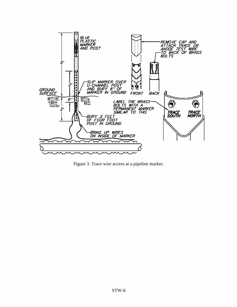
STW-6
Figure 3. Trace wire access at a pipeline marker.
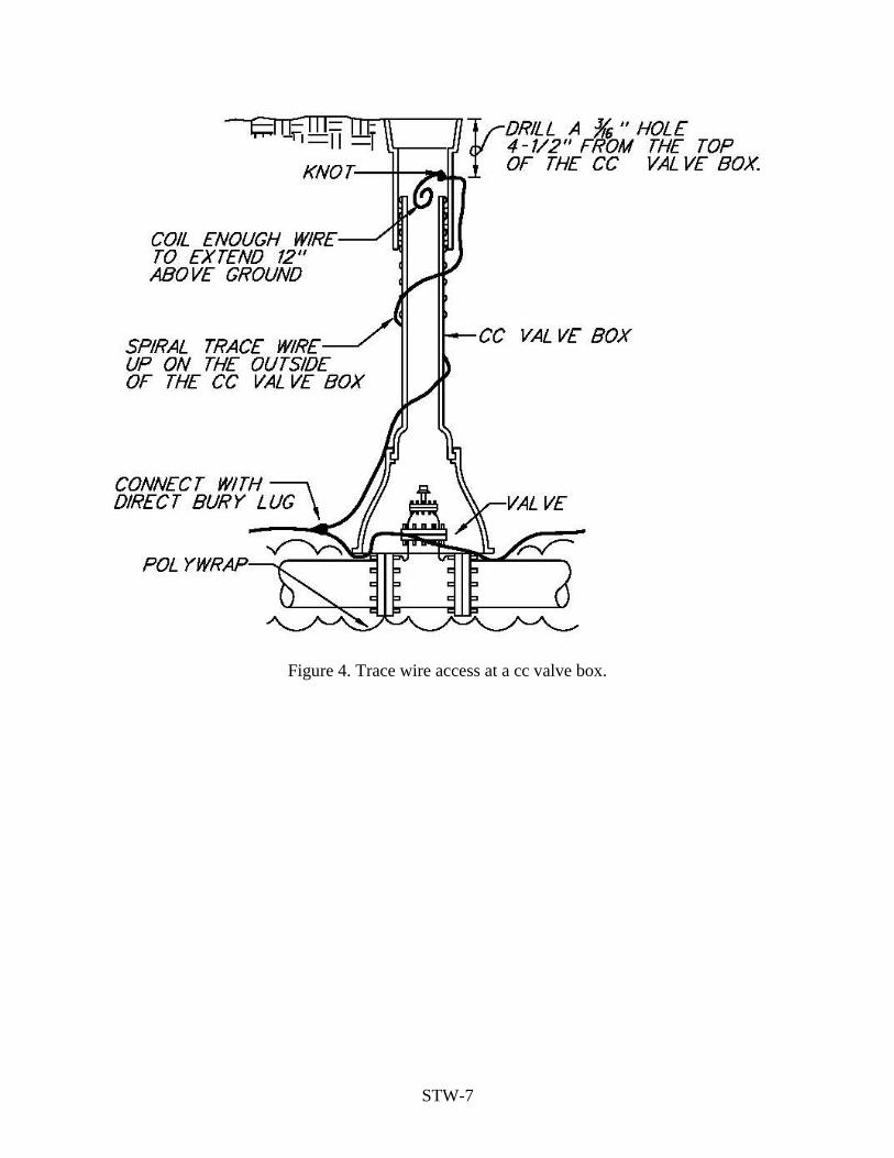
STW-7
Figure 4. Trace wire access at a cc valve box.

STW-8
Figure 5. Trace wire access at a hydrant.

CHAPTER 46-5
CONSTRUCTION DETAILS

ELEVATION
DISPOSITION OF BARS DETAIL
2:1 SLOPE2"
6"
D
2'-6"'S'
'S'
2:1 SLO
PE
6"
A
AH2"
'S'2'-6"
A
PLAN
E
BA
C
D 1/2 L
L
1/2 L
1 1/2 :1, 2:1 OR 4:1 SLOPE
SECTION A-A
F
2"
2"
'S' 1'-3"2"
3"
2"
2" 2"
NO.4 STRAIGHT BARS HORIZONTAL @ 1'-7"MAX. C/C BOTH FACES- TOP AND BOTTOMBARS TO BE FULL LENGTH- ALL ENDWALLS.
NO.4 BENT BARS @1'-0" C/C ALL ENDWALLS.
NO.4 STRAIGHT BARSHORIZONTAL @ 1'-0"C/C BOTH SIDES OFOPENING FOR 36"DIA. TO 72" DIA.PIPEENDWALLS INCLUSIVE.
1-NO.4STRAIGHT BARHORIZONTAL-ALL ENDWALLS.
2-NO.4 STRAIGHT BARSHORIZONTAL FOR 36"DIA. TO 72" DIA. PIPEENDWALLS INCLUSIVE.
'S' DISTANCES4" FOR 12" DIA. TO 21" DIA. PIPES INCLUSIVE.6" FOR 24" DIA. TO 36" DIA. PIPES INCLUSIVE.8" FOR 42" DIA. TO 72" DIA. PIPES INCLUSIVE.
NOTES:1. SPECIFICATIONS: LATEST TOWN OF MIDDLETOWN2. CONCRETE SHALL BE CLASS B3. REINFORCING: DEFORMED STEEL BARS-NO.44. CHAMFER: ALL EXPOSED EDGES 1"x1" OR AS
DIRECTED5. SAFETY GRATING REQUIRED IN RESIDENTIAL AREAS
ON UPSTREAM HEADWALLS
QUANTITIES FOR ESTIMATING PURPOSES ONLYDIMENSIONS
1'-9"21 9" 6" 6"2.40
72
5460
4842
15.90
28.2719.64
12.579.62
24
3336
3027
7.075.944.913.983.14
20"12"
20"20"
12"12"
16"16"
12"12"
3'-8"12"
12"12"
3'-8"3'-8"
10"10"
3'-2"3'-2"
16"14"14"
9"12"
9"14"14"
9"9"
6"10"
6"2'-5"3'-2"
2'-5"6"6"
2'-5"2'-5"
1215
INCHES
18
D
0.79
1.771.23
SQ.FT.AREA
OPENING
9" 6"
9"9"
6"6"
A B
1'-9"
6"6"
1'-9"1'-9"
6"
C E
10'-3"2'-6"9" 701.14
11.46
1.561.822.222.484.165.076.097.628.82
7'-0"6'-0"5'-6"5'-0"4'-6"
12"
12"12"
12"12"
24'-2"
31'-8"26'-8"
21'-8"19'-2"
4'-0"3'-9"3'-6"3'-0"2'-9"
12"12"
12"9"9"
16'-8"15'-5"14'-2"
12'-10"11'-6"
275
377304
206244
182105988880
C.Y.CONC.
0.610.770.95
QUANTITIES
2'-3"2'-0"1'-9"9"
9"9"
F H
6'-6"
9'-0"7'-9"
L
41
5447
LBS.STEEL
4-NO.4 STRAIGHT BARS VERTICALIN FRONT FACE FOR 12" DIA. TO21" DIA. PIPE ENDWALLS INCLUSIVE.
2 NO. 4 STRAIGHT BARS HORIZONTAL1 EACH FACE FOR 36" DIA. TO 72"DIA. PIPE ENDWALLS INCLUSIVE.
NO.4 STRAIGHT BARS VERTICAL@ 1'-6" MIN. TO 2'-0" MAX.FRONT FACE FOR 24" DIA. TO 72"DIA. PIPE ENDWALLS INCLUSIVE.
ISSUED 2010
REVISED
SOURCE DEPARTMENT OFPUBLIC WORKS STANDARD NO. D-1
STORM DRAINAGE DETAILS
STRAIGHT HEADWALL
MDSHA

QUANTITIES IN TABLE TO BE USED FOR ESTIMATING ONLY
DIMENSIONS
10"
1'-0"
1'-0"
15.9
AREASQ.FT.
12.57
19.64
INCHES
60
OPENING
54
48
D B
1'-4"
1'-8"
1'-8"
C
3'-2"
3'-8"
3'-8"
E
3'-3"
2'-9"
3'-0"
F
7'-0 3/4 "
7'-8 1/2 "
8'-5"
G
6'-0"
5'-0"
5'-6"
H
1'-3"
BARS DETAILDISPOSITION OF
2"
3"
10"
2"
2"
45°
2'-6"
1'-0"
2:12"
1 #4 BENT BAR HORIZONTAL
1 #4 BENT BAR HORIZONTAL
B
2"
3"
PLAN
A
D
45°B
ELEVATIONA
2" 2'-6"
1'-0"
2"2:1
3'-7 1/2 "
3'-1 1/2"
2'-10 3/4"
5'-10"
4'-10"
5'-4"
J
7'-7 1/4"
K
6'-3 1/2"
6'-10 1/2"
8'-0 1/4"
6'-8 1/2"
7'-3 1/2"
L
6'-11"
5'-9"
6'-2 1/4"
MCONC.
N
6'-8"
5'-6"
6'-2"
OLBS.
262
301
361
STEEL
6.0
5.3
4.3
C.Y.
VOL.
ISOMETRIC VIEW
SECTION A-A
SECTION B-B
GL
3"
M
KN
H O
D
1 1/2 :1, 2:1 OR 4:1 SLOPE
J
3"
2"
1'-0"
E
1'-0
" B
F
C
3"
4 #6 BENT BARS HORIZONTAL2 EACH FACE
#4 STRAIGHT BARS VERTICAL @1'-6"MIN.TO 2'-0"MAX. FRONT FACE
#4 BARSHORIZONTAL @
1'-0" C/C BELOWOPENING
#4 BARS HORIZONTAL @ 1'-7" MAX. C/CBOTH FACES BOTTOM BARS BENT ALONG
ENDWALL OTHERS STRAIGHT.
#4 BENT BARS @ 1'-0" C/C BOTHWINGWALLS- ALL ENDWALLS
2 #4 STRAIGHT BARS HORIZONTAL,1 EACH WINGWALL
#4 STRAIGHT BARS HORIZONTAL@ 1'-0" C/C @ BOTH SIDES OFOPENINGNOTES
SPECIFICATIONS: LATEST TOWN OF MIDDLETOWNCONCRETE SHALL BE CLASS BREINFORCING: DEFORMED STEEL BARS #4 & #6CHAMFER: ALL EXPOSED EDGES 1"X1" OR AS DIRECTEDSAFETY GRATING REQUIRED IN RESIDENTIAL AREAS ON UPSTREAM HEADWALLS
ISSUED 2010
REVISED
SOURCE DEPARTMENT OFPUBLIC WORKS STANDARD NO. D-2
STORM DRAINAGE DETAILS
STANDARD HEADWALL(48", 54" & 60" PIPE)
MDSHA

10'-3 1/4"
11'-1 3/4"
12'-0"
12'-9 1/2"
QUANTITIES IN TABLE TO BE USED FOR ESTIMATING ONLY
KJHGFECB
84
78
66
72
3'-0"
3'-0"
2'-6"
2'-6"
38.48
33.20
28.27
23.80
1'-6"
1'-6"
1'-3"
1'-3"
13'-0 1/2"
13'-10"
12'-1"
11'-2 1/2"3'-0"
3'-3"
3'-6"
3'-9"5'-6"
5'-6"
4'-9"
4'-9"
7'-10"
7'-4"
6'-10"
6'-4"
7'-9 1/2 "
8'-4"
6'-8 1/2"
7'-3"
BARS DETAILDISPOSITION OF
2"
OPENING
1'-0"
2"
2"
2"
3"
{{
45°
2"2"
DIMENSIONS
B
B
PLAN
A
D
45°
G
PONML
3"-11"
9'-3"
10'-1 1/4"
10'-9"
11'-6 1/2"13'-2 1/2"
11'-6 3/4"
10'-8 1/2"
12'-5"
4'-6"
4'-0"
3'-5"
2'-6"
2'-6"
2'-0"
2'-0"
7'-10 1/2"
8'-6 3/4"
9'-0 3/4"
7'-4 1/2"
14.7
13.3
9.7
10.9
984
865
645
585
SECTION B-B
3"
ISOMETRIC VIEW
NM
L
K
H
1'-0"
BP
O
D
F
E
1'-0"C
ELEVATION
2:12"
2'-6"
12"
A2
"
12"
2"2:1
2'-6"
SECTION A-A
3"
J
3"
2"
2"
NOTESSPECIFICATIONS: LATEST TOWN OF SMYRNA CONCRETE SHALL BE CLASS BREINFORCING: DEFORMED STEEL BARS #4 & #6CHAMFER: ALL EXPOSED EDGES 1"x1" OR AS DIRECTEDSAFETY GRATING REQUIRED IN RESIDENTIAL AREAS ON UPSTREAM HEADWALLS
#4 STRAIGHT BARS VERTICAL@ 1'-6" MIN. TO 2'-0" MAX. INFRONT FACE
4-#6 BENT BARS HORIZONTAL2 EACH FACE
#4 BENT BARS @1'-0" C/C BELOWOPENING
3/4 " O HOOK BOLTS @ 1'-6"C/C AROUND PIPE ARCH WHENMETAL PIPE IS USED.
1 1/2 :1,2:1 OR 4:1 SLOPE
#4 LONG BENT BARS HORIZONTAL#4 SHORT BENT BARS HORIZONTALALT. 1 WITH 1 @ 6"C/C#4 LONG BENT BARS HORIZONTAL#4 SHORT BENT BARS HORIZONTALALT. 1 WITH 2 RESP. 4"C/C
B-66B-72
B-78B-84
#4 BARS HORIZONTAL @ 1'-7"MAX. C/C BOTH FACES BOTTOMBARS BENT ALONG ENDWALLOTHERS STRAIGHT.
1#4 BENT BAR HORIZONTAL
2 #4 BENT BARSHORIZONTAL
#4 BENT BARS BOTH WINGWALLSALL ENDWALLS.
#4 BENT BARS @ 1'-0" C/C BOTHSIDES OF OPENING
2 #4 STRAIGHT BARS HORIZONTAL,1 EACH WINGWALL
DINCHES
AREASQ.FT.
VOL.CONC.C.Y.
STEELLBS.
ISSUED 2010
REVISED
SOURCE DEPARTMENT OFPUBLIC WORKS STANDARD NO. D-3
STORM DRAINAGE DETAILS
MDSHA
45° STANDARD HEADWALL(66" TO 84" PIPE)

QUANTITIES FOR ESTIMATING PURPOSES ONLY
2'-6"
43X6838X6034X53
16.612.910.2
29X4532X49
27X4224X3822X3419X30 3.3
4.15.16.37.48.8
OPENING
14X23
DSQ.FT.
1.8
AREA
8" 1'-11"6"9"
12"12"12" 16"
16"20"
12"9"9"9"9"
14"14"
14"14"16"
3'-2"3'-8"
3'-2"
12"10"10"
2'-5"2'-5"
3'-2"2'-9"2'-5"
10"6"6"6"
10"
ELEVATION
A
9" 8"
B
1'-11"
DIMENSIONS
C
6"
E
2"
6"
2'-6"3"
SPANRISE
6"
S
3"
PLAN
EB
CA
1/2 LSPAN
L
SECTION A-A
DISPOSITION OF BARS DETAIL
QUANTITIES
12" 10'-6"2'-6"
14-10"
18'-0"17'-0"
22'-8"20'-4"
16'-0"
13'-6"12'-6"
4'-0"4'-5"
4'-10"15"
14"15"
2'-11"3'-1"3'-4"3'-7"
3'-10"
13"
14"
13"
13"
14"
4.405.236.52
'
1.151.741.922.192.614.08
2'-2"12"
F H
8'-7"
L
0.88
210266307
141124116100
202
6356
A
A
2"
H
F
2"
1/2 L
3"
'S'2" 1'-3"
2"
2"
2"
2"
'S' DISTANCES6" FOR 14" x 23" TO 27" x 42" INCLUSIVE.8" FOR 29" x 45" TO 43" x 68" INCLUSIVE.
GENERAL NOTESSPECIFICATIONS: LATEST TOWN OF SMYRNACONCRETE: SHALL BE CLASS BREINFORCEMENT: DEFORMED STEEL BARS NO.4CHAMFER: ALL EXPOSED EDGES 1"x1" OR AS DIRECTED.SAFETY GRATING REQUIRED IN RESIDENTIAL AREAS ON
UPSTREAM HEADWALLS
RISE x SPANINCHES
NO.4 STRAIGHT BARS VERTICAL@ 1'-6" MIN. TO 2'-0" MAX.FRONT FACE FOR 22" x 34" TO43" x 68" PIPE ENDWALLSINCLUSIVE.
2:1 SLOPE 2:1 SLO
PE
2-NO.4 STRAIGHT BARS HORIZONTAL1 EACH FACE FOR 32"x49" TO43"x68" PIPE ENDWALLS INCLUSIVE.
4-NO.4 STRAIGHT BARS VERTICAL INFRONT FACE FOR 14"x23" TO 19"x30"
PIPE ENDWALLS.
1-NO.4STRAIGHT BARHORIZONTALALL ENDWALLS.
2-NO.4 STRAIGHT BARSHORIZONTAL FOR 32"x49" TO43"x68" PIPE ENDWALLS INCLUSIVE.
NO.4 STRAIGHT BARSHORIZONTAL @ 1'-0"C/C BOTH SIDES OFOPENING FOR 32"x49"TO 43"x64" PIPEENDWALLS INCLUSIVE.
NO.4 STRAIGHT BARSHORIZONTAL @ 1'-7" MAX.C/C BOTH FACES- TOP ANDBOTTOM BARS TO BE FULLLENGTH- ALL ENDWALLS.
NO.4 BENT BARS @1'-0" C/C ALL ENDWALLS.
2:1 OR 4:1 SLOPE
A
CONC.C.Y.
STEELLBS.
ISSUED 2010
REVISED
SOURCE DEPARTMENT OFPUBLIC WORKS STANDARD NO. D-4
STORM DRAINAGE DETAILS
STRAIGHT HEADWALL(HORIZONTAL ELLIPTICAL CONCRETE PIPE)
MDSHA

1/2 L
QUANTITIES FOR ESTIMATING PURPOSES ONLY
2'-6"
71X47 19.64 12"64X4357X3849X3342X2935X2428X2024X1821X1517X13
15.9012.57
7.079.62
4.91
12"
12"12"
9"9"
SQ.FT.1.231.77
3.142.40
9"9"
9"9"
OPENINGD AREA
A
2"
EB
AC
21'-9"3'-8"20" 12" 4'-11"12" 6.05 24321'-9"
17'-11"17'-11"13'-8"13'-8"9'-6"9'-6"9'-6"6'-3"
3'-8"3'-2"3'-2"2'-5"2'-5"1'-9"1'-9"1'-9"1'-9"
16"16"20"
14"14"
10"
12"10"
6"6"
6"6"6"6"
6"6"
6"6"
2'-9"
12"
12"12"
12"12"
3'-9"
4'-7"4'-2"
3'-2"
1'-10"2'-0"2'-3"2'-5"9"
9"9"9"
DIMENSIONS
B C E F H L
4.34
6.274.73
1.921.98
186186243
9695
0.960.96
0.540.98
5555
3856
QUANTITIES
6"
3"
'S'
6"
2'-6"3"
AH
A
2"
L
SPAN 1/2 L
2"
3"
F
2"
1'-3"'S'
2"
2"
2"
2"
INCHESSXR
CONC.C.Y.
STEELLBS.
'S' DISTANCES4" FOR 17" x 13" TO 24" x 18" INCLUSIVE.6" FOR 28" x 20" TO 42" x 29" INCLUSIVE.8" FOR 49" x 33" TO 71" x 47" INCLUSIVE.
GENERAL NOTESSPECIFICATIOINS: LATEST TOWN OF SMYRNACONCRETE SHALL BE CLASS BREINFORCING: DEFORMED STEEL BARS NO.4CHAMFER: ALL EXPOSED EDGES 1"x1" OR AS DIRECTED.SAFETY GRATING REQUIRED IN RESIDENTIAL AREAS ON
UPSTREAM HEADWALLS
NO.4 STRAIGHT BARS VERTICAL@ 1'-6" MIN. TO 2'-0" MAX.FRONT FACE FOR 35" x 24" TO71" x 47" PIPE ENDWAALSINCLUSIVE.
RISESPAN
2:1 SLOPE 2:1 SLO
PE
2-NO.4 STRAIGHT BARS HORIZONTAL1 EACH FACE FOR 49"x33" TO71"x47" PIPE ENDWALLS INCLUSIVE.
4-NO.4 STRAIGHT BARS VERTICALIN FRONT FACE FOR 17"x13" TO28"x20" PIPE ENDWALLS INCLUSIVE.
1-NO.4 STRAIGHTBAR HORIZONTALALL ENDWALLS.
2-NO.4 STRAIGHT BARSHORIZONTAL FOR 49"x33" TO71"x47" PIPE ENDWALLS INCLUSIVE.
NO.4 STRAIGHT BARSHORIZONTAL @ 1'-0"C/C BOTH SIDES OFOPENING FOR 49"x33"TO 71"x47" PIPEENDWALLS INCLUSIVE.
NO.4 STRAIGHT BARSHORIZONTAL @ 1'-7" MAX.C/C BOTH FACES-TOP ANDBOTTOM BARS TO BE FULLLENGTH- ALL ENDWALLS.
NO.4 BENT BARS @ 1'-0" C/CALL ENDWALLS.
2:1 OR 4:1 SLOPE
DISPOSITION OF BARS DETAILPLAN
SECTION A-A
ELEVATION
A
ISSUED 2010
REVISED
SOURCE DEPARTMENT OFPUBLIC WORKS STANDARD NO. D-5
STORM DRAINAGE DETAILS
STRAIGHT HEADWALL(METAL ARCH PIPE)
MDSHA

INCHES
OPENING
SECTION A-A
HA
2"
6"
2"
2'-6"
A
EB
AC
L
'S'
B
PLAN
A CE
A
7260544842
3633
L
D
18
242730
21
1512
D
D+6"
END VIEW
1'-3"
DISPOSITION OF BARS DETAIL
2" 'S'
3"
2"
2"
2"
2"
2"
2"
2"
QUANTITIES FOR ESTIMATING PURPOSES ONLY
3'-6"
4'-0"
4'-6"5'-0"5'-6"6'-0"7'-0"
6"9"
15.9019.6428.27
5.947.079.62
12.57
12"12"12"
20"
20"20"
12"12"
12"9"
16"16"
14"16"
2'-6"
3'-8"
3'-8"3'-8"3'-2"
3'-2"3'-2"2'-5"
12"12"
12"
6"10'10"10"
3'-9"
1.772.403.14
3.984.91
1.230.79SQ.FTAREA
6"9"
9"9"
9"14"14"14"
6"
9"9"
A
6"6"
B
2'-5"2'-5"
2'-5"1'-9"
1'-9"1'-9"1'-9"
6"6"6"6"
6"
C
6"
2'-3"
2'-9"
3'-0"
2'-6"
E
1'-9"2'-0"
H
DIMENSIONS
8'-0"
597496438
303235148
10.86
12.6917'-0"15'-6"14'-0"12'-6"11'-0"9'-6"8'-9"
9.17
6.12
7.34
2.924.99
341
140
115106
5'-0"
7'-3"6'-6"5'-9"
4'-3"3'-6"
L
1.17 68
1.842.112.57
1.38 77
0.760.99 61
55
QUANTITIES
CONC.C.Y.
STEELLBS.
2 NO.4 STRAIGHT BARS VERTICAL IN FRONT FACEFOR 12" DIA TO 21" DIA PIPE ENDWALLS INCLUSIVE.
2 NO.4 BENT BARS HORIZONTAL1 EACH FACE FOR 36" DIA. TO 72"DIA. PIPE ENDWALLS INCLUSIVE.
1 1/2 :1,2:1
OR 4:1 SLOPE
NO.4 BENT BARS @ 1'-0" C/CBOTH ENDWALLS.
2:1 SLOPE
NO.4 STRAIGHT BARS VERTICAL @ 1'-6" MINTO 2'-0" MAX.FRONT FACE FOR 12" DIA.TO21" DIA. PIPE ENDWALLS INCLUSIVE.
4 NO.4 STRAIGHT BARS HORIZONTAL 2 EACHWINGWALL FOR 36" DIA. TO 72" DIA. PIPE ENDWALL.
2 NO.4 STRAIGHT BARS VERTICALIN FRONT FACE FOR 12" DIA.TO 21"DIA. PIPE ENDWALLS INCLUSIVE.
NO.4 STRAIGHT BARS VERTICAL@ 1'-6" MIN. TO 2'-0" MAXFRONT FACE FOR 24" DIA.TO 72"DIA.PIPE ENDWALLS INCLUSIVE.
1 1/2 :1,2:1OR 4:1 SLOPE
2:1 SLOPE
NO.4 STRAIGHT BARS HORIZONTAL @ 1'-7"MAX C/C BOTH FACES-LAP 1'-3" TOP & BOTTOMBARS @ CORNER- BOTH WINGWALLS-ALLENDWALLS.
NO.4 STRAIGHT BARS HORIZONTAL@ 1'-0" C/C BOTH SIDES OFOPENING BOTH WINGWALLS FOR 36"DIA.TO 72" DIA.PIPE ENDWALLS INCL.
2 NO.4 STRAIGHT BARSHORIZONTAL 1 EACHWINGWALL- ALL ENDWALLS.
'S' DISTANCES4" FOR 12" DIA. TO 21" DIA. PIPES INCLUSIVE.6" FOR 24" DIA. TO 36" DIA. PIPES INCLUSIVE.8" FOR 42" DIA. TO 72" DIA. PIPES INCLUSIVE.
GENERAL NOTESSPECIFICATIONS: LATEST TOWN OF SMYRNACONCRETE SHALL BE CLASS BREINFORCING: DEFORMED STEEL BARS - NO.4CHAMFER: ALL EXPOSED EDGES 1"x 1" OR AS DIRECTED.SAFETY GRATING REQUIRED IN RESIDENTIAL AREAS ON UPSTREAM HEADWALLS
ISSUED 2010
REVISED
SOURCE DEPARTMENT OFPUBLIC WORKS STANDARD NO. D-6
STORM DRAINAGE DETAILS
"L" HEADWALL
MDSHA
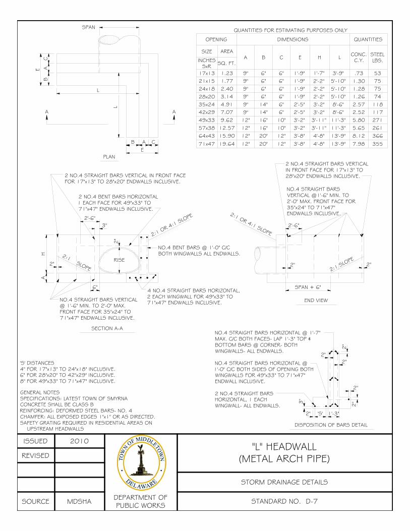
C
SECTION A-A
A
2"RISE
6"
H
A2
"
2'-6"3"
PLAN
L
EB A
CA
B
E
L
SPAN
END VIEW
DISPOSITION OF BARS DETAIL
2"
2"
3"
2"
'S' 1'-3"
2"
2"
2"
2"
SPAN + 6"
2"
2'-6"
3'-8"
3'-8"3'-2"3'-2"2'-5"2'-5"1'-9"1'-9"1'-9"1'-9"
QUANTITIES FOR ESTIMATING PURPOSES ONLY
DIMENSIONS
6"9"7.0742x29 14"
19.64
15.9012.579.62
A
71x47
64x4357x3849x33
20"
20"16"16"12"
12"12"
12"
10"10"12"
12"
SQ. FT.
4.913.142.401.771.23
AREA
35x2428x2024x1821x1517x13
SIZE
OPENING
6"6"6"6"
14"9"9"9"9"9"
A B
6"6"6"6"6"
C E
1178'-6"3'-2" 2.5211'-3"11'-3"13'-9"
13'-9"4'-8"
4'-8"3'-11"3'-11"
7.98
8.125.655.80
366
355
261271
QUANTITIES
8'-6"5'-10"5'-10"5'-10"3'-9"
L
3'-2"2'-2"2'-2"2'-2"
1'-7"
H
2.571.261.281.30.73
75
11874
7553
INCHESSxR
CONC.C.Y.
STEELLBS.
2 NO.4 STRAIGHT BARS VERTICAL IN FRONT FACEFOR 17"x13" TO 28"x20" ENDWALLS INCLUSIVE.
2 NO.4 BENT BARS HORIZONTAL1 EACH FACE FOR 49"x33" TO71"x47" ENDWALLS INCLUSIVE.
NO.4 BENT BARS @ 1'-0" C/CBOTH WINGWALLS ALL ENDWALLS.
2:1 OR 4:1 SLOPE
2:1 SLOPE
NO.4 STRAIGHT BARS VERTICAL@ 1'-6" MIN. TO 2'-0" MAX.FRONT FACE FOR 35"x24" TO71"x47" ENDWALLS INCLUSIVE.
4 NO.4 STRAIGHT BARS HORIZONTAL,2 EACH WINGWALL FOR 49"x33" TO71"x47" ENDWALLS INCLUSIVE.
2 NO.4 STRAIGHT BARS VERTICALIN FRONT FACE FOR 17"x13" TO28"x20" ENDWALLS INCLUSIVE.
NO.4 STRAIGHT BARSVERTICAL @1'-6" MIN. TO2'-0" MAX. FRONT FACE FOR35"x24" TO 71"x47"ENDWALLS INCLUSIVE.2:1 OR 4:1 SLOPE
2:1 SLOPE
NO.4 STRAIGHT BARS HORIZONTAL @ 1'-7"MAX. C/C BOTH FACES- LAP 1'-3" TOP &BOTTOM BARS @ CORNER- BOTHWINGWALLS- ALL ENDWALLS.
NO.4 STRAIGHT BARS HORIZONTAL @1'-0" C/C BOTH SIDES OF OPENING BOTHWINGWALLS FOR 49"x33" TO 71"x47"ENDWALL INCLUSIVE.
2 NO.4 STRAIGHT BARSHORIZONTAL, 1 EACHWINGWALL- ALL ENDWALLS.
'S' DISTANCES4" FOR 17"x13" TO 24"x18" INCLUSIVE.6" FOR 28"x20" TO 42"x29" INCLUSIVE.8" FOR 49"x33" TO 71"x47" INCLUSIVE.
GENERAL NOTESSPECIFICATIONS: LATEST TOWN OF SMYRNACONCRETE SHALL BE CLASS BREINFORCING: DEFORMED STEEL BARS- NO. 4CHAMFER: ALL EXPOSED EDGES 1"x1" OR AS DIRECTED.SAFETY GRATING REQUIRED IN RESIDENTIAL AREAS ON
UPSTREAM HEADWALLS
ISSUED 2010
REVISED
SOURCE DEPARTMENT OFPUBLIC WORKS STANDARD NO. D-7
STORM DRAINAGE DETAILS
"L" HEADWALL(METAL ARCH PIPE)
MDSHA

SURFACE (WEARING) COURSE
BASE COURSE
GABC 1'2'
NEW ROAD EXISTING TOWN ROAD
EDG
E EX
ISTI
NG
PAVEM
ENT
3'
SAW
CUT
LINE
SEAL JOINT WITHHOT-POUREDBITUMINOUSJOINT SEALER
REMOVEEXISTING
PAVEMENTSECTION
REMOVE EXISTINGWEARING COURSE TODEPTH OF WEARING
COURSE OF NEW ROAD
ISSUED 2010
REVISED
SOURCE DEPARTMENT OFPUBLIC WORKS STANDARD NO. R-1
ROAD DETAILS
PAVEMENT TIE-IN SECTION

STANDARD CURB& GUTTER
2 TO 1MAXIMUM
SLOPE
4" GRADEDAGGREGATE
4,000 PSICONCRETE +5%AIR ENTRAINMENT
NOTES:
1. TWENTY-EIGHT (28) DAY SPECIFIED COMPRESSIVE STRENGTH FOR CONCRETE MIX @3,500 PSI.
2. ALL SIDEWALK SHALL BE FOUR INCHES (4") MINIMUM THICKNESS, UNLESS OTHERWISE NOTED.
3. SIDEWALK ACROSS DRIVEWAYS AND DRIVEWAY APRONS SHALL BE SIX INCHES (6") MINIMUMTHICKNESS, UNLESS OTHERWISE NOTED OVER 6" GABC.
4. SIDEWALKS SHALL HAVE DUMMY JOINTS EVERY FIVE FEET (5') AND SHALL HAVE EXPANSION JOINTSINSTALLED EVERY SIXTEEN FEET (20').
5. A PVC SLEEVE OF FOUR INCHES (4") IN DIAMETER, INSTALLED TO A DEPTH OF A LEAST TWELVEINCHES (12") BELOW FINISHED GRADE AND INTO SOIL, SHALL BE PROVIDED FOR EACH SIGN POSTLOCATED WITHIN THE SIDEWALK PRIOR TO INSTALLATION OF CONCRETE MIX.
6. ALL UNPAVED AREAS WITHIN RIGHT-OF-WAY SHALL BE SEEDED AND MULCHED WITH A MINIMUM OFSIX INCHES (6") OF TOP SOIL OR SODDED TO OBTAIN A THICK STAND OF GRASS.
2% 4"
1'-0" 6' MINIMUMVARIES(5'-10")
ISSUED 2010
REVISED
SOURCE DEPARTMENT OFPUBLIC WORKS STANDARD NO. R-2
ROAD DETAILS
SIDEWALK

ISSUED 2010
REVISED
SOURCE DEPARTMENT OFPUBLIC WORKS STANDARD NO. R-3
ROAD DETAILS
RESIDENTIAL ENTRANCE(WITH GRASS STRIP)

ISSUED 2010
REVISED
SOURCE DEPARTMENT OFPUBLIC WORKS STANDARD NO. R-4
ROAD DETAILS
RESIDENTIAL ENTRANCE(WITHOUT GRASS STRIP)

6" CONCRETE (MIN.)(4000 PSI - AIR ENTRAINED)
COMPACTED SUBGRADE
6" GRADED AGGREGATE (MIN.)
ISSUED 2010
REVISED
SOURCE DEPARTMENT OFPUBLIC WORKS STANDARD NO. R-5
ROAD DETAILS
RESIDENTIAL DRIVEWAY SECTION(CONCRETE)

6" GRADED AGGREGATE (MIN.)
3" HOT MIX ASPHALT (MIN.)
COMPACTED SUBGRADE
ISSUED 2010
REVISED
SOURCE DEPARTMENT OFPUBLIC WORKS STANDARD NO. R-6
ROAD DETAILS
RESIDENTIAL DRIVEWAY SECTION(ASPHALT)
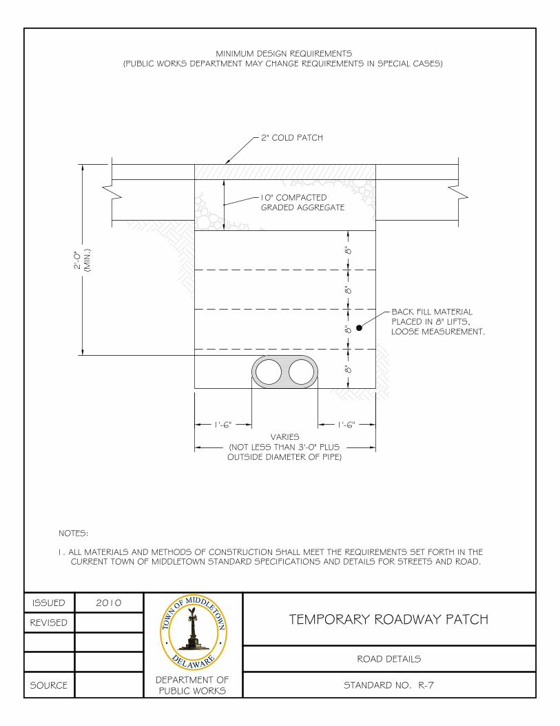
NOTES:
1. ALL MATERIALS AND METHODS OF CONSTRUCTION SHALL MEET THE REQUIREMENTS SET FORTH IN THECURRENT TOWN OF MIDDLETOWN STANDARD SPECIFICATIONS AND DETAILS FOR STREETS AND ROAD.
MINIMUM DESIGN REQUIREMENTS(PUBLIC WORKS DEPARTMENT MAY CHANGE REQUIREMENTS IN SPECIAL CASES)
2'-0
"(M
IN.)
8"
1'-6"VARIES
(NOT LESS THAN 3'-0" PLUSOUTSIDE DIAMETER OF PIPE)
1'-6"
10" COMPACTEDGRADED AGGREGATE
2" COLD PATCH
BACK FILL MATERIALPLACED IN 8" LIFTS,LOOSE MEASUREMENT.8
"8
"8
"
ISSUED 2010
REVISED
SOURCE DEPARTMENT OFPUBLIC WORKS STANDARD NO. R-7
ROAD DETAILS
TEMPORARY ROADWAY PATCH

NOTES:
1. THIS IS A MINIMUM PATCH. IF THE EXISTING ROADWAY HAS A HEAVIER CROSS SECTION THAN SHOWN HERE, ITWILL BE REPLACED WITH THAT CROSS SECTION, OR AS DIRECTED BY THE PUBLIC WORKS DIRECTOR.
2. ALL MATERIALS AND METHODS OF CONSTRUCTION SHALL MEET THE REQUIREMENTS SET FORTH IN THE CURRENTTOWN OF MIDDLETOWN STANDARD SPECIFICATIONS AND DETAILS FOR STREETS AND ROADS.
8"
1'-6"VARIES
(NOT LESS THAN 3'-0" PLUSOUTSIDE DIAMETER OF PIPE)
1'-6"
8"
8"
8"
BACK FILL MATERIALPLACED IN 8" LIFTS,LOOSE MEASUREMENT.
8" COMPACTED GRADED AGGREGATE
3" TYPE "C" HOT MIX IN TWO COURSES
FULL-DEPTH SAW CUT FULL-DEPTH SAW CUT
2'-0
"(M
IN.)
1'-0"1'-0" 1'-0"
1'-0"
7'-0" PLUS OUTSIDE DIAMETER OF PIPE
PATCHES MUST HAVE A MINIMUM LENGTH OF 7 FEET PLUSOUTSIDE DIAMETER OF PIPE (AS MEASURED ALONG THEROADWAY CENTERLINE) AND THE WIDTH OF THE LANE ORLANES DISTURBED.
ISSUED 2010
REVISED
SOURCE DEPARTMENT OFPUBLIC WORKS STANDARD NO. R-8
ROAD DETAILS
PERMANENT ROADWAY PATCH

16'-0"
12'-0"
GRADEDAGGREGATE(6" MIN.)
COMPACTED EARTH(95% MOD. PROCTOR)
6" TOP SOIL WITH GRASS PAVERSOR OTHER APPROVED SOILREINFORCEMENT PRODUCT
NOTES:
1. MINIMUM WIDTH: 16'-0"
2. TREES/SHRUBS: MINIMUM 3'-0" MAXIMUM 5'-0" IN HEIGHT AT 20'-0" O.C.
3. REFER TO DELAWARE STATE FIRE PREVENTION REGULATIONS FOR ALL
REQUIREMENTS.
4. GEOTEXTILE SEPARATOR TO BE INSTALLED BOTH ABOVE AND BELOW
GRADED AGGREGATE BASE.
GEOTEXTILESEPARATOR
ISSUED 2010
REVISED
SOURCE DEPARTMENT OFPUBLIC WORKS STANDARD NO. R-9
ROAD DETAILS
FORESTRY LANE

SELECT BACKFILL MATERIAL COMPACTED IN 8" LIFTS TO 95% MOD.PROCTOR DENSITY UNDER ROADWAY AREAS TO A POINT 2 FT. BELOWGRADE. THE TOP 2 FT. SHALL BE COMPACTED TO 95% MOD.PROCTOR DENSITY. AREAS OUTSIDE OF ROADWAYS SHALL BECOMPACTED TO 92% MOD. PROCTOR DENSITY UNLESS OTHERWISENOTED ON THE PLANS.
6" BELOW PIPE
6" ABOVE PIPE
OD18"MIN.
18"MIN.
SEE NOTE #5
12
"(T
YP.)
SEE NOTE 4.
NOTES:
1. TRENCH SHALL BE BRACED OR SHEETED IN ACCORDANCE WITH OSHA REGULATIONS.
2. PROVIDE BEARING FULL LENGTH OF BARREL.
3. DIG BELL HOLES.
4. INSTALL METALLIC DETECTOR TAPE FOR GRAVITY MAINS LOCATED OUTSIDE THE ROAD RIGHT-OF-WAY ANDFORCEMAINS PER SPECS AT 1' BELOW FINISHED GRADE.
5. TRACER WIRE TO BE INSTALLED ON ALL FORCEMAINS.
AASHTO NO. 57CRUSHED STONE BEDDING
ISSUED 2010
REVISED
SOURCEDEPARTMENT OFPUBLIC WORKS STANDARD NO. S-1
SANITARY SEWER DETAILS
PIPE BEDDING & TRENCH DETAIL

S-5S-15
S-6
S-6
S-5
S-15
TOW
N
ISSUED 2010
REVISED
SOURCEDEPARTMENT OFPUBLIC WORKS STANDARD NO. S-2
SANITARY SEWER DETAILS
STANDARD 48" PRECAST CONCRETEMANHOLE
NEW CASTLECOUNTY

S-5S-15
S-6
S-6
S-5
S-15
TOW
N
ISSUED 2010
REVISED
SOURCEDEPARTMENT OFPUBLIC WORKS STANDARD NO. S-3
SANITARY SEWER DETAILS
STANDARD 60" PRECAST CONCRETEMANHOLE
NEW CASTLECOUNTY

NOTES:
1. ONLY ONE INSIDE DROP CONNECTION PER MANHOLE WILL BE ALLOWED, UNLESS APPROVED BY THE TOWN.
2. THE DROP FITTING SHALL NOT EXTEND INTO THE AREA THAT IS DEFINED BY THE PROJECTION OF THE MANHOLE
ENTRANCE VERTICALLY DOWN TO THE MANHOLE BOTTOM. IF NECESSARY, MANHOLE FRAME, COVER, CONE
SECTION, AND STEPS SHALL BE REMOVED AND PLACED TO ALLOW FOR UNOBSTRUCTED ENTRY AND EXIT.
3. INFLUENT PIPE SLOPE SHALL NOT EXCEED 5%.
4. MAXIMUM SIZE OF INFLUENT PIPE IS 8".
5. PROPOSED MANHOLE WITH INSIDE DROP MUST BE A MIN. OF 5' IN DIAMETER. INSIDE DROPS PROPOSED AT AN
EXISTING MANHOLE OF LESS THAN 5' DIAMETER WILL BE REVIEWED ON A CASE BY CASE BASIS.
ISSUED 2010
REVISED
SOURCEDEPARTMENT OFPUBLIC WORKS STANDARD NO. S-4
SANITARY SEWER DETAILS
INSIDE DROP MANHOLE CONNECTION

TOWN OF MIDDLETOWN
ISSUED 2010
REVISED
SOURCEDEPARTMENT OFPUBLIC WORKS STANDARD NO. S-5
SANITARY SEWER DETAILS
STANDARD MANHOLE FRAME AND COVER
NEW CASTLECOUNTY

ISSUED 2010
REVISED
SOURCEDEPARTMENT OFPUBLIC WORKS STANDARD NO. S-6
SANITARY SEWER DETAILS
SANITARY SEWER MANHOLE STEPS
NEW CASTLECOUNTY
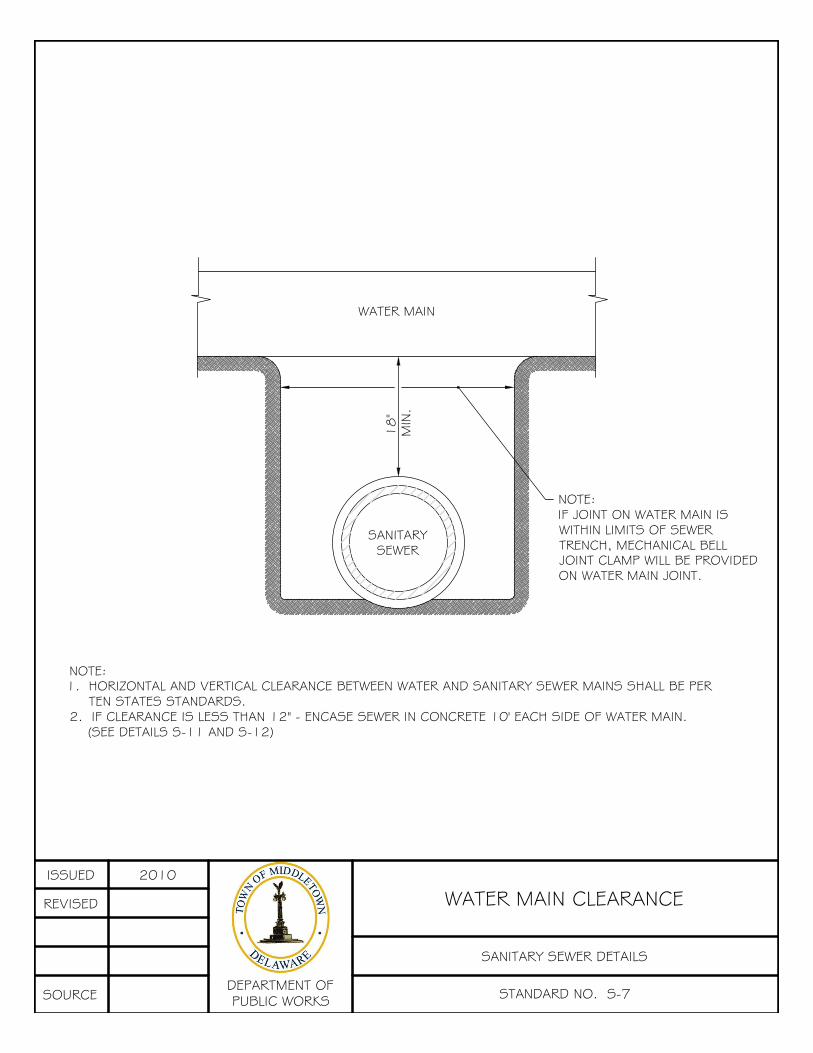
NOTE:IF JOINT ON WATER MAIN ISWITHIN LIMITS OF SEWERTRENCH, MECHANICAL BELLJOINT CLAMP WILL BE PROVIDEDON WATER MAIN JOINT.
WATER MAIN
SANITARYSEWER
18"
MIN
.
NOTE:1. HORIZONTAL AND VERTICAL CLEARANCE BETWEEN WATER AND SANITARY SEWER MAINS SHALL BE PER
TEN STATES STANDARDS.2. IF CLEARANCE IS LESS THAN 12" - ENCASE SEWER IN CONCRETE 10' EACH SIDE OF WATER MAIN.
(SEE DETAILS S-11 AND S-12)
ISSUED 2010
REVISED
SOURCEDEPARTMENT OFPUBLIC WORKS STANDARD NO. S-7
SANITARY SEWER DETAILS
WATER MAIN CLEARANCE

SEE NOTE#3
NOTE #2 BELOW.3,000 PSI CONCRETEENCASEMENT.
NOTES:
1. S.H.C. TO NEW MAIN USES STANDARD "Y" BRANCH.2. S.H.C. TO EXISTING MAIN USES GENECO SEALITE TYPE "E" WYE SEWERPIPE SADDLE OR EQUAL STAINLESS STEEL STRAPS.3. CLEAN OUT TO BE LOCATED AT RIGHT-OF-WAY/PROPERTY LINE.
EMBOSS"S" ONFACE OFCURB (2"MIN.)
R.O.W.
ISSUED 2010
REVISED
SOURCEDEPARTMENT OFPUBLIC WORKS STANDARD NO. S-8
SANITARY SEWER DETAILS
4" AND 6" DROP HOUSE CONNECTION(NEW CONSTRUCTION)

CHANNEL LINING NOTES: 1. CHANNEL LINING SHALL BE CONCRETE. MINIMUM 4" THICK. 2. WIDTH OF CHANNEL SHALL MATCH INSIDE DIAMETER OF INCOMING AND OUTGOING PIPES. BLEND CHANNEL LINING FOR SMOOTH CONTOUR BETWEEN PIPES. 3. CONCRETE CHANNELS SHALL BE FORMED AS SHOWN. F's FOR CAST-IN-PLACE CHANNELS AND BENCHES SHALL BE 4000 PSI @ 28 DAYS. FOR PRECAST CHANNELS AND BENCHES, F'c = 4000 PSI MINIMUM. 4. ALL INVERT ELEVATIONS SHALL BE AS SHOWN ON THE CONTRACT DRAWINGS.
ISSUED 2010
REVISED
SOURCEDEPARTMENT OFPUBLIC WORKS STANDARD NO. S-9
SANITARY SEWER DETAILS
TYPICAL CHANNELIZATION OF MAINLINESEWER MANHOLES

1/4 O.D.
NOTES:
1. TRENCH SHALL BE BRACED OR SHEETED AS REQUIRED.2. PROVIDE BEARING FULL LENGTH OF BARREL.3. DIG BELL HOLES.4. INSTALL BARE COPPER AWG #10 DETECTOR WIRE ABOVE PIPE. PROVIDE ACCESS FOR MONITORING AT 400'
(MAX.) INTERVAL PER SPECS.5. INSTALL METALLIC DETECTOR TAPE PER SPECS.6. POUR CONCRETE AGAINST UNDISTURBED EARTH, REMOVE SHEETING BEFORE POURING CONCRETE OR LEAVE LOWER PORTION OF SHEETING IN PLACE.7. SELECT BACKFILL MATERIAL COMPACTED IN 8" LIFTS TO 95% MOD. PROCTOR DENSITY WITHIN ROADWAY
AREAS, 92% MOD. PROCTOR DENSITY OUTSIDE ROADWAY AREAS.
OD18"MIN.
18"MIN.
SEE NOTE 4.
SEE NOTE 7.
12
"(T
YP.)
12
"(T
YP.)
SEE NOTE 5.
SEE NOTE 6.
3/4 O.D.
CRADLE DETAILS
HIGH CRADLELOW CRADLE
6" BELOW PIPE
6" ABOVE PIPE
OD6"MIN.
6"MIN.
SEE NOTE 4.
SEE NOTE 7.
12
"(T
YP.)
SEE NOTE 5.
ENCASEMENT DETAILS
SEE NOTE 6.
NORMAL MAXIMUM PAYMENT
PIPE CU. FT. PER LIN FT.
DIAMETER CONC. ENCASEMENT
6" 1.53
8" 2.55
10" 2.95
12" 3.63
15" 4.20
18" 5.71
21" 6.35
24" 8.22
27" 8.94
30" 9.83
33" 12.16
36" 13.09
42" 15.22
48" 19.83
54" 22.97
60" 24.95
66" 27.71
NORMAL MAXIMUM PAYMENT
PIPE CU. FT. PER LIN FT.
DIAMETER
6" 1.28 0.90
8" 1.58 1.03
10" 1.86 1.22
12" 2.33 1.51
15" 2.82 1.73
18" 4.02 2.35
21" 4.52 2.62
24" 5.95 3.34
27" 6.58 3.70
30" 7.42 4.18
33" 9.42 5.08
36" 10.53 5.65
42" 12.30 6.64
48" 16.25 8.49
54" 18.46 9.64
60" 20.80 10.95
66" 23.08 12.25
HIGH CRADLE LOW CRADLE
3000 PSI CONCRETE
3000 PSICONCRETE
4" MIN. BELOWPIPE
OD18"MIN.
18"MIN.
ISSUED 2010
REVISED
SOURCEDEPARTMENT OFPUBLIC WORKS STANDARD NO. S-10
SANITARY SEWER DETAILS
CONCRETE ENCASEMENT AND CRADLE

CROSSING UTILITY
NOTE:
SANITARY SEWER MAINS SHALL BE ENCASED AS SHOWN WHEN LESS THAN 18" OF VERTICALSEPARATION EXISTS BETWEEN THE SANITARY SEWER MAIN AND WATER MAIN AND WHEN LESS THAN 12"OF SEPARATION EXISTS BETWEEN THE SANITARY SEWER MAIN AND OTHER UTILITIES. THE ENCASEMENTLENGTH SHALL BE A MINIMUM OF TEN FEET (10') EITHER SIDE OF CROSSING UTILITY.
L = LAYING LENGTH OF SANITARY SEWER PIPE.
CONCRETE ENCASEMENT DETAILN.T.S
SANITARYSEWER MAIN
CROSSINGUTILITY
L
L/2L/2
6" M
IN.
AA
SECTION A-A
3000 P.S.I.CONCRETE
3000 P.S.I.CONCRETE
18" 18"
6" MIN.
ISSUED 2010
REVISED
SOURCEDEPARTMENT OFPUBLIC WORKS STANDARD NO. S-11
SANITARY SEWER DETAILS
CONCRETE ENCASEMENT AT UTILITYCROSSINGS
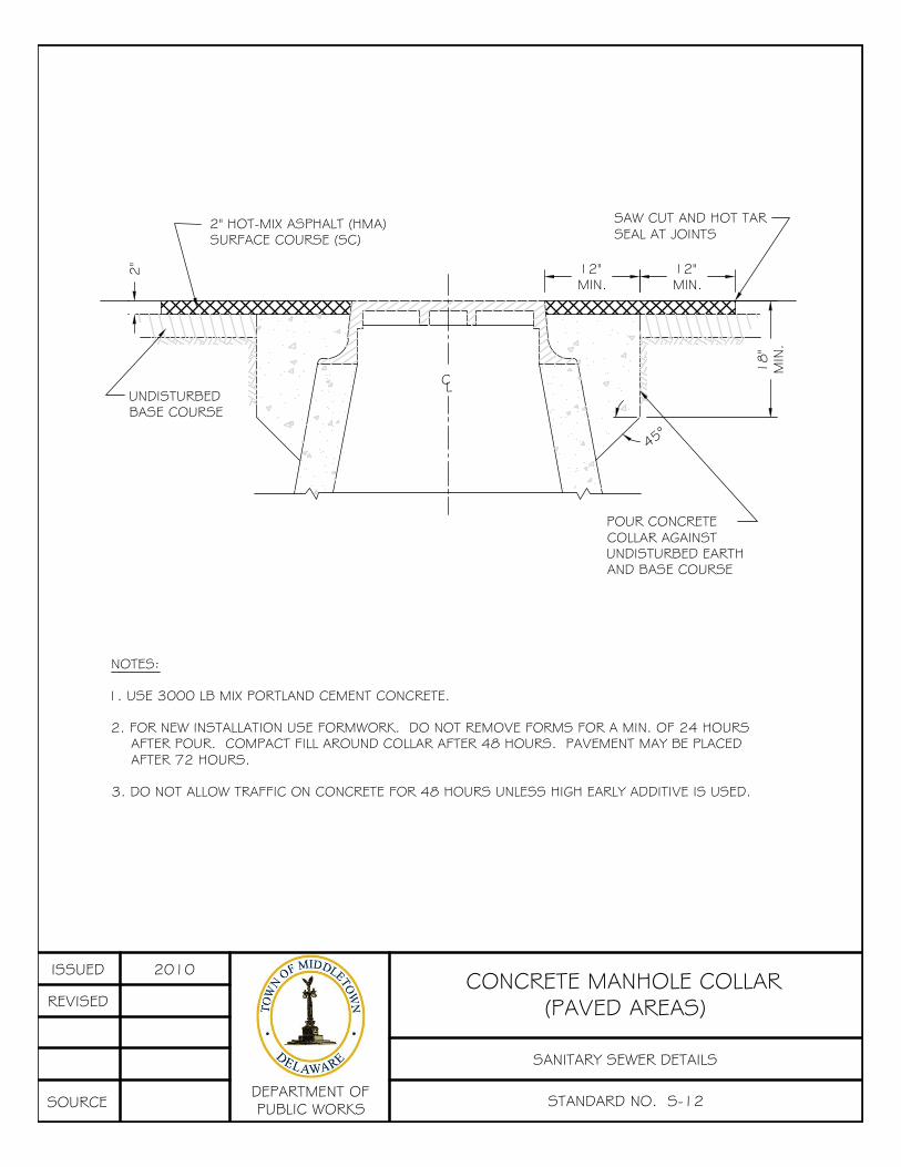
NOTES:
1. USE 3000 LB MIX PORTLAND CEMENT CONCRETE.
2. FOR NEW INSTALLATION USE FORMWORK. DO NOT REMOVE FORMS FOR A MIN. OF 24 HOURSAFTER POUR. COMPACT FILL AROUND COLLAR AFTER 48 HOURS. PAVEMENT MAY BE PLACEDAFTER 72 HOURS.
3. DO NOT ALLOW TRAFFIC ON CONCRETE FOR 48 HOURS UNLESS HIGH EARLY ADDITIVE IS USED.
2" HOT-MIX ASPHALT (HMA)SURFACE COURSE (SC)
SAW CUT AND HOT TARSEAL AT JOINTS
12"MIN.
12"MIN.
18
"M
IN.
2"
UNDISTURBEDBASE COURSE
POUR CONCRETECOLLAR AGAINSTUNDISTURBED EARTHAND BASE COURSE
CL
45°
ISSUED 2010
REVISED
SOURCEDEPARTMENT OFPUBLIC WORKS STANDARD NO. S-12
SANITARY SEWER DETAILS
CONCRETE MANHOLE COLLAR(PAVED AREAS)

NOTES:
1. USE 3000 LB MIX PORTLAND CEMENT CONCRETE.
2. FOR NEW INSTALLATION USE FORMWORK. DO NOT REMOVE FORMS FOR A MIN. OF 24HOURS AFTER POUR. COMPACT FILL AROUND COLLAR AFTER 48 HOURS. PAVEMENT MAY BEPLACED AFTER 72 HOURS.
3. TOP SOIL, SEED AND MULCH ENTIRE DISTURBED AREA.
12"MIN.
18
"M
IN.
ROUND CORNER(TYP.)
POUR CONCRETECOLLAR AGAINSTUNDISTURBED EARTH
CL
1:24
2"
45°
ISSUED 2010
REVISED
SOURCEDEPARTMENT OFPUBLIC WORKS STANDARD NO. S-13
SANITARY SEWER DETAILS
CONCRETE MANHOLE COLLAR(NON-PAVED AREAS)

REMOVE HOT-MIX & CONC. COLLARFROM AROUND MANHOLE
REMOVE & DISPOSE OFEXIST. FRAME & COVER
PLACE NEW FRAME &COVER (DETAIL S-5) TO EXIST. GRADE,RECOLLAR (DETAIL S-12) & PLACEHOT-MIX PATCH
12"
16
"
2" HOTMIX
RIS
ER R
ING
S (SEE
DET
AIL
S-1
5)
MAX.
OF
12
"
12"
SAWCUT AND HOTTAR SEAL AT JOINTS
ISSUED 2010
REVISED
SOURCEDEPARTMENT OFPUBLIC WORKS STANDARD NO. S-14
SANITARY SEWER DETAILS
MANHOLE FRAME REPLACEMENT

ISSUED 2010
REVISED
SOURCEDEPARTMENT OFPUBLIC WORKS STANDARD NO. S-15
SANITARY SEWER DETAILS
RISER RING DETAIL
NEW CASTLECOUNTY

6" PVC (SDR-26)
2% SLOPE
MIN. 3'-6"
ROADWAY
CURB
BRASS RECESSED CAP,BRASS LUG AND FERRULE
EMBOSS "S" ON FACEOF CURB (2" MIN.)
MAGNETIC TAPE TO HOUSE BYPLUMBING CONTRACTOR. BURYTAPE 6" BELOW FINISH GRADE
TO SEWER MAIN
MAGNETIC TAPE TO FACEOF CURB BY TOWN.BURY TAPE 6" BELOWFINISH GRADE.
45° PVC "Y" BRANCH
6" PVC
PVC SDR-26 6"x4" COUPLINGINCREASER WHEN REQUIRED
FROM HOUSE
SELECT FILL
R.O.W.
ISSUED 2010
REVISED
SOURCEDEPARTMENT OFPUBLIC WORKS STANDARD NO. S-16
SANITARY SEWER DETAILS
TYPICAL CLEANOUT

Fully supported with #57 clean stone
3000 PSICONCRETE
EXISTINGSANITARYSEWER MAIN
ELBOW
6" PVC (SDR-26)
MAGNETIC TAPETO FACE OFCURB. BURYTAPE 6" BELOWFINISH GRADE
CURB
BRASS RECESSEDCAP, BRASS LUGAND FERRULE
R.O.W.
FROM HOUSE
2% SLOPE
MIN. 3'-6"
ROADWAY
EMBOSS "S" ON FACEOF CURB (2" MIN.)
ISSUED 2010
REVISED
SOURCEDEPARTMENT OFPUBLIC WORKS STANDARD NO. S-17
SANITARY SEWER DETAILS
SEWER HOUSE CONNECTION(NEW CONSTRUCTION)

GENCO SEALTITE TYPE "E" WYESEWER PIPE SADDLE OR
APPROVED EQUAL
3000 PSICONCRETE
EXISTINGSANITARYSEWER MAIN
ELBOW
6" PVC (SDR-26)
MAGNETIC TAPETO FACE OFCURB. BURYTAPE 6" BELOWFINISH GRADE
CURB
BRASS RECESSEDCAP, BRASS LUGAND FERRULE
R.O.W.
FROM HOUSE
2% SLOPE
MIN. 3'-6"
ROADWAY
EMBOSS "S" ON FACEOF CURB (2" MIN.)
ISSUED 2010
REVISED
SOURCEDEPARTMENT OFPUBLIC WORKS STANDARD NO. S-18
SANITARY SEWER DETAILS
STANDARD HOUSE CONNECTION(EXISTING SEWER MAIN)

UNDISTURBEDCOMPACTED EARTH
FINISHED GRADE
ADJUSTABLECURB BOX
CURB STOP
CORPORATION STOP
BRICK BLOCKING
WATER MAIN
3'-0
" MIN
.
COPPER PIPE SERVICE
6"
EXTENSIONSTEM
EMBOSS "W" ON FACEOF CURB (2" MIN.)
3'-6
" MIN
.
3/4" SERVICE FITTINGSTRAIGHT 3 PARTUNION WITH I.P.THREADED COPPERFLARE NUT ORCOMPRESSION FITTING
3'-0"
3/4" K-COPPER
MAGNETIC TAPE
NOTES:
1. INSTALL ALL ITEMS AS SHOWN OR APPROVED EQUAL.
2. NO GALVANIZED PIPING OR FITTINGS TO BE USED.
3. MAGNETIC TAPE TO BE INSTALLED ABOVE PIPING, BURIED 6" BELOW GRADE.
SERVICE SIZE
3/4"(MINIMUM ALLOWABLE SIZE PER DPW)
CORPORATION STOP
MUELLER H-15000 ORCOMP. ASSEMBLY
H-15008
CURB STOP
MUELLER TYPEH-15209
CURB BOX
MUELLER H-10385EXTENSION RANGE,
33" TO 46"
R.O
.W.
LINE
ISSUED 2010
REVISED
SOURCE DEPARTMENT OFPUBLIC WORKS STANDARD NO. W-1
WATER DETAILS
STANDARD SERVICE CONNECTIONWITH CURB BOXAPRIL 2013

CO
NFL
ICTI
NG
UTI
LITY
PRO
POSED
GRO
UND
SURFA
CE
CEN
TER O
NE
FULL
LEN
GTH
OF
PIPE
ON C
ENTE
RLI
NE
OF
CRO
SSIN
G U
TILI
TY
COVER TYP.3'-6"
CO
NC
RET
E ANC
HO
R(S
EE D
ETAIL
W-8
)
CO
NC
RET
E TH
RUST
BLO
CK
(SEE
DET
AIL
W-9
)
OUTS
IDE
DIA
MET
ER1
8" M
IN.
CLE
AR
CO
NC
RET
E TH
RUST
BLO
CK
(SEE
DET
AIL
W-9
)
CO
NC
RET
E ANC
HO
R(S
EE D
ETAIL
W-8
)
45° BENDS - TYP.
ISSUED 2010
REVISED
SOURCE DEPARTMENT OFPUBLIC WORKS STANDARD NO. W-2
WATER DETAILS
WATER MAIN CROSSING STORM &SANITARY SEWER

SELECT BACKFILL MATERIAL COMPACTED IN 8" LIFTS TO 95% MOD.PROCTOR DENSITY UNDER ROADWAY AREAS. AREAS OUTSIDE OFROADWAYS SHALL BE COMPACTED IN 8" LIFTS TO 92% MOD. PROCTORDENSITY UNLESS OTHERWISE NOTED ON THE PLANS.
OD18"MIN.
18"MIN.
SEE NOTE 4.
12
"-1
8"
(TYP
.)
SEE NOTE 5.
NOTES:
1. TRENCH SHALL BE BRACED OR SHEETED IN ACCORDANCE WITH OSHA REGULATIONS.
2. PROVIDE BEARING FULL LENGTH OF BARREL.
3. DIG BELL HOLES.
4. INSTALL TRACE WIRE IN ACCORDANCE WITH THE SUPPLEMENTAL TRACE WIRE SPECIFICATIONS OF CHAPTER46 OF THE CODE OF THE TOWN OF MIDDLETOWN.
5. INSTALL METALLIC DETECTOR TAPE PER SPECS.
ISSUED 2010
REVISED
SOURCE DEPARTMENT OFPUBLIC WORKS STANDARD NO. W-3
WATER DETAILS
PIPE BEDDING & TRENCH DETAILSEPT 2012
APRIL 2013

CURB
PROPOSED GRADE
2 1/2" HOSE CONNECTION
ROAD SURFACE
NOTES:
1. ALL ITEMS TO BE AS SHOWN OR APPROVED EQUAL.
2. HYDRANT MUST BE STRAPPED AND MECHANICALLY RESTRAINED (I.E. MEGA LUG).
WATEROUS PACERWB-67-250 HYDRANT 5 1/4"MAIN VALVE OPEN LEFT. (5SIDED OPERATING LUGS)
BARREL SAFETY FLANGEMUST BE 2" ABOVEFINISHED GRADE.
DRAIN RING SHALL BEKEPT CLEAN OF CONCRETE
1/3 YARD OF WASHED #57STONE PLACED AROUND BLEEDHOLES PER SPECIFICATIONS.
SEE STD DETAILSFOR THRUST BLOCKS
DISTANCE FROM CENTER OFHYD. TO FACE OF CURB
4 1/2" PUMPERNOZZEL FACING
STREET
WATER MAINCENTERLINE
6" CLASS 52 DIP
6" RESILIENT WEDGE GATEMJ VALVE (OPEN LEFT)
HEAVY DUTY CAST IRON3-PIECE SCREW TYPE WATER
VALVE BOX INCLUDING EXTRADEEP LID WITH TWO (2) HOLES
AND "WATER" CAST IN THE TOP.
UNDISTURBEDEARTH (TYP)
HYDRANTRESTRAINING TEEWITH INTEGRALLYCAST STANDARD
M.J. GLAND
2'-0"
20
"
CONCRETE COLLAR(SEE DETAIL W-15)
ISSUED 2010
REVISED
SOURCE DEPARTMENT OFPUBLIC WORKS STANDARD NO. W-4
WATER DETAILS
STANDARD FIRE HYDRANT INSTALLATIONSEPT 2012
NOV 2012

NOTES:1. CONCRETE STRENGTH - MIN. = 3,000 PSI AT 28 DAYS.
2. STANDARD THRUST BLOCKING IS BASED ON THE FOLLOWING ASSUMPTIONS AND LIMITATIONS, IF THESE CONDITIONSARE NOT MET, SPECIAL DESIGN IS REQUIRED:
A) STATIC PRESSURE IS 150 PSI OR LOWER. B) DEPTH FROM FINISHED GRADE TO TOP OF PIPE ASSUMED TO EQUAL 3'-6" OR DEEPER. C) ELEVATION OF GROUNDWATER TABLE ASSUMED TO BE BELOW BOTTOM OF THE BLOCK.
3. IF SOIL CONDITIONS ARE SOFT OR ORGANIC SPECIAL DESIGN IS REQUIRED (MIN. SOIL BEARING PRESSURE OF 3,000PSF).
4. FOR LARGER PIPE DIAMETER, SEE DRAWINGS FOR SPECIAL DETAILS.
5. ALL DIMENSIONS ARE MINIMUMS EXCEPT WHERE LARGER DIMENSIONS WILL INTERFERE WITH THE PIPE JOINTS OF NOTFACILITATE BOLT REMOVAL ON MECHANICAL JOINT FITTINGS.
6. MECHANICAL JOINTS (i.e. MEGA LUGS) MAY BE USED IN LIEU OF THRUST BLOCKS FOR HORIZONTAL BENDS.
CONCRETE TRUST BLOCKS
UNDISTURBED EARTH
UNDISTURBED EARTH
H
H/2
H/2
TMIN
C L
CL
F/2 F/2(F MIN)
A
A
L
L/2L/2
ELEVATION
SECTION A-A
D/4
D/4
CONCRETETHRUSTBLOCK
BENDTYPE
PIPEDIAMETER
THRUST BLOCK DIMENSIONSL H F T
1/32
6" 1'-0" 1'-2" 8" 7"8" 1'-4" 1'-4" 8" 7"
10" 1'-8" 1'-6" 8" 8"12" 2'-0" 1'-8" 8" 8"14" 2'-4" 1'-10" 10" 9"16" 2'-6" 2'-0" 11" 9"
1/16
6" 1'-6" 1'-2" 8" 8"8" 2'-0" 1'-4" 8" 9"
10" 3'-0" 1'-6" 8" 10"12" 3'-6" 1'-8" 8" 11"14" 4'-0" 1'-10" 10" 1'-0"16" 4'-6" 2'-0" 11" 1'-2"
1/8
6" 1'-3" 1'-2" 8" 8"8" 1'-8" 1'-4" 8" 9"
10" 2'-1" 1'-6" 8" 10"12" 2'-6" 1'-10" 8" 11"14" 2'-9" 2'-2" 10" 1'-0"16" 3'-4" 2'-6" 11" 1'-2"
1/4
6" 1'-0" 1'-2" 8" 1'-8"8" 1'-4" 1'-4" 8" 1'-7"
10" 1'-6" 2'-1" 8" 1'-7"12" 1'-8" 2'-6" 8" 1'-6"14" 2'-1" 2'-6" 10" 1'-8"16" 2'-5" 3'-0" 11" 1'-8"
ISSUED 2010
REVISED
SOURCE DEPARTMENT OFPUBLIC WORKS STANDARD NO. W-5
WATER DETAILS
THRUST BLOCKS FORHORIZONTAL BENDS

NOTES:
1. SEE BLOCKING DESIGN REQUIREMENT NOTES, STANDARD DETAIL W-5.
2. MECHANICAL JOINTS (i.e. MEGA LUGS) MAY BE USED IN LIEU OF THRUST BLOCKS FOR HORIZONTAL BENDS.
A
F/2F/2
F
A
UNDISTURBED EARTH SECTION A-AELEVATION
PLAN
L/2
L/2
L
DIAMETERBRANCH
O.D.RUN
1/2 O.D. RUN
TEE
T (MIN.)
H
H/2
H/2
D/4
1/2" DIAMETER RUNCONC. THRUSTBLOCKTEE
UNDISTURBED EARTH
FINISHED GRADE
CONC. THRUST BLOCK
NOMINAL DIAMETER OF BRANCH6" 8" 10" 12" 14" 16"
L 1'-0" 1'-4" 2'-0" 2'-0" 2'-4" 2'-8"H 1'-4" 1'-8" 2'-0" 2'-6" 3'-0" 3'-4"T 8" 9" 10" 1'-0" 1'-1" 1'-2"F 1'-0" 1'-4" 1'-4" 1'-4" 1'-6" 1'-8"
CL
ISSUED 2010
REVISED
SOURCE DEPARTMENT OFPUBLIC WORKS STANDARD NO. W-6
WATER DETAILS
THRUST BLOCKS FOR TEES &TAPPING SLEEVES

NOTES:
1. SEE BLOCKING DESIGN REQUIREMENT NOTES, STANDARD DETAIL W-5.
2. MECHANICAL JOINTS (i.e. MEGA LUGS) MAY BE USED IN LIEU OF THRUST BLOCKSFOR PLUGS AND CAPS.
NOMINAL DIAMETER OF BRANCH6" 8" 10" 12" 14" 16"
L 1'-3" 1'-8" 2'-1" 2'-6" 3'-0" 3'-4"H 11" 1'-2" 1'-6" 1'-9" 2'-0" 2'-4"T 6" 8" 8" 10" 11" 1'-0"F 8" 10" 1'-0" 1'-2" 1'-4" 1'-6"
FINISHED GRADE
CONC. THRUSTBLOCK
CONC. THRUSTBLOCK
UNDISTURBED EARTH
UNDISTURBED EARTH
CAP OR PLUGCAP OR PLUG
L/2
L/2
LF
F/2
F/2H/2
H/2
H
T(MIN.)
SECTION A-AELEVATION
PLAN
CLCL
ISSUED 2010
REVISED
SOURCE DEPARTMENT OFPUBLIC WORKS STANDARD NO. W-7
WATER DETAILS
THRUST BLOCKS FOR PLUGS & CAPS

NOTES:
1. SEE BLOCKING DESIGN REQUIREMENT NOTES, STANDARD DETAIL W-5.
L
W/2
W/2
W
(8" MIN.)ONE PIPE DIA.
DOFFSET
L/2 L/2L ℄ BEND
WHERE 4 REINFORCINGBARS ARE USED,SYMETRICALLY PLACE2 BARS ON BEND ANDOTHER 2 AS SHOWN
12" MIN.CLEARANCE
UNDISTURBEDGROUND
REINFORCING BARS BENT TO CONFORM TO OUTSIDEDIAMETER OF PIPE OR BEND WITH STANDARD HOOKON EACH END. EMBED MINIMUM 36 BAR DIAMETERSINCLUDING THE HOOK. COAT ALL EXPOSED STEEL WITHFIELD APPLIED COATING.
6" MIN. 2/3 D (8" MIN.)
1"x2" DOUBLE ACTINGSTEEL WEDGES (TYP.)
SECTION A-AELEVATION
PLAN
BEND SIZE6" 8" 10" 12" 14" 16"
1/32
L 2'-0" 2'-6" 2'-9" 3'-0" 3'-6" 4'-0"W 1'-6" 1'-6" 2'-5" 3'-0" 3'-3" 3'-6"D 1'-3" 1'-9" 1'-9" 2'-0" 2'-0" 2'-0"
OFFSET 0'-6" 0'-6" 0'-6" 0'-6" 0'-6" 0'-6"REBAR 3 - #6 3 - #6 3 - #6 3 - #6 3 - #6 3 - #6
1/16
L 2'-6" 2'-8" 3'-10" 4'-0" 4'-8" 5'-6"W 2'-0" 3'-4" 3'-8" 4'-0" 4'-2" 4'-4"D 1'-9" 2'-3" 2'-6" 2'-6" 2'-6" 2'-6"
OFFSET 1'-0" 1'-0" 1'-0" 1'-0" 1'-0" 1'-0"REBAR 3 - #6 3 - #6 3 - #6 3 - #6 3 - #6 3 - #6
1/8
L 3'-0" 4'-0" 4'-6" 4'-9" 5'-6" 6'-6"W 2'-6" 3'-0" 4'-0" 4'-6" 4'-10" 5'-2"D 2'-6" 2'-9" 3'-0" 3'-6" 3'-9" 4'-0"
OFFSET 1'-3" 1'-6" 1'-9" 2'-0" 2'-3" 2'-6"REBAR 3 - #6 3 - #6 3 - #6 3 - #6 3 - #6 3 - #6
CL
ISSUED 2010
REVISED
SOURCE DEPARTMENT OFPUBLIC WORKS STANDARD NO. W-8
WATER DETAILS
ANCHORAGE FOR 1/32, 1/16 & 1/8UPPER VERTICAL BENDS

NOTES:
1. SEE BLOCKING DESIGN REQUIREMENT NOTES, STANDARD DETAIL W-5.
A
A
L/2
LL/2
D/2
T
W/2 W/2
W
CL
CL
UNDISTURBED EARTH
CONC. THRUST BLOCK
SECTION A-AELEVATION
D
2/3 D (8"MIN.)
BEND SIZE6" 8" 10" 12" 14" 16"
1/32L 0'-8" 0'-8" 0'-10" 0'-10" 1'-2" 1'-4"W 1'-2" 1'-4" 1'-6" 1'-8" 1'-10" 2'-0"T 0'-7" 0'-7" 0'-8" 0'-8" 0'-9" 0'-9"
1/16L 0'-9" 1'-0" 1'-6" 1'-9" 2'-0" 2'-3"W 1'-2" 1'-4" 1'-6" 1'-8" 1'-10" 2'-0"T 0'-7" 0'-7" 0'-8" 0'-8" 0'-9" 0'-9"
1/8L 1'-3" 1'-8" 2'-1" 2'-6" 3'-0" 3'-4"W 1'-2" 1'-4" 1'-6" 1'-10" 2'-2" 2'-6"T 0'-7" 0'-8" 0'-10" 0'-11" 1'-1" 1'-3"
ISSUED 2010
REVISED
SOURCE DEPARTMENT OFPUBLIC WORKS STANDARD NO. W-9
WATER DETAILS
THRUST BLOCKS FOR 1/32, 1/16 & 1/8LOWER VERTICAL BENDS

END OF WATERMAIN
2" SCHEDULE 80THREADED PVC MALEADAPTER
MJ CAP WITH 2"FEMALE THREADEDPORT. (PROVIDERETAINER GLAND)
NOTES:
1. FLUSHING HYDRANT SHALL BE MODEL NO. TF-500 AS MANUFACTURED BY THE JOHN C. KUPFERLE FOUNDRYCO., ST. LOUIS, MO. OR APPROVED EQUAL.
2. HYDRANTS SHALL BE COMPRESSION TYPE CLOSING WITH THE PRESSURE AND FURNISHED WITH A 2" FIP INLET.WATER PRESSURE ALONE SHALL CLOSE THE VALVE. HYDRANTS SHALL BE OPERATED BY USE OF A PORTABLETOP STOCK COUPLING WITH THE HYDRANT AT OR NEAR THE GROUND LINE.
3. HYDRANTS SHALL BE ARRANGED FOR DEPTH OF BURY SUITABLE FOR WATER MAIN DESIGN DEPTH OF COVER.WORKING PARTS, THREAD PROTECTOR AND OPERATING ROD SHALL BE BRASS AND REMOVABLE FROM THEHYDRANT WITHOUT THE NEED FOR EXCAVATION. BRASS THREAD PROTECTOR SHALL HAVE A 2" SQUARE NUT.
4. BRICK BLOCKING SHALL BE PROVIDED AS SHOWN AS WELL AS PARALLEL TO THE 2" SCHEDULE 80 PIPE TOFULLY SUPPORT THE VALVE BOX.
TF500
THREADPROTECTOR
ADJUSTABLE VALVE BOXFORD OR APPROVED EQUAL
BRICK BLOCKING REQUIREDSEE NOTE #4
AASHTO NO. 57 STONE(3 CU. FT)
SPECIFIEDDEPTH OFBURY
OPERATING NUT
6" MIN.8" MAX.
GROUND SURFACE VALVE BOX LID
PEA GRAVEL
DRAIN
UNDISTURBED EARTH
2" SCHEDULE 80 PVC
ISSUED 2010
REVISED
SOURCE DEPARTMENT OFPUBLIC WORKS STANDARD NO. W-10
WATER DETAILS
STANDARD FLUSHING HYDRANT

STANDARD CAST IRONROADWAY BOX
STANDARD CURB STOP.BOTTOM OF CURB STOP TOREST ON CONCRETE THRUSTBLOCK.
1 1/2" EL.
1 1/2" NIPPLE
1 1/2" EL.
CONCRETE THRUST BLOCK
STANDARD CAP
FINISHED GRADE
1 1/2" K-COPPER PIPE6" BELOW GRADE
WATER MAIN
NOTES:
1. ALL 1-1/2" FITTINGS TO BE COPPER OR BRASS WITH FLARE OR COMPRESSION CONNECTIONS.
2. ALL 1-1/2" PIPING TO BE K-COPPER.
ISSUED 2010
REVISED
SOURCE DEPARTMENT OFPUBLIC WORKS STANDARD NO. W-11
WATER DETAILS
TEMPORARY CAP & BLOW-OFF

DRILL 134" DIA. HOLE FOR TOUCH-READ DEVICE.
(MIN. 212" FROM NEAREST EDGE OF PIT LID AND
MIN. 1" FROM NEAREST UNDERNEATH RIB.)
TYPICALINSTALLATION
FRAME & COVERPLAN VIEW
20''
+
+
+ +
SIX RIBSEQUALLY SPACED
CONC.COLLAR
9"
12"MIN.
1, 1 1/2" OR 2" M.I.P. THREADED INLETAND OUTLET CONNECTORS
DOUBLE VALVE COPPER SETTER (15" TALL) WITH CHECK VALVE(FORD 70 SERIES OR APPROVED EQUAL)
FINISHED GRADE
35
" (M
IN.)
2"
15
" (M
IN.)
18
" 18
"(MIN
.)
HEAVY DUTY PIT FRAME AND COVER FORDMODEL MC-30-T, EAST JORDAN MODEL1048 OR APPROVED EQUAL WITH TOWNOF MIDDLETOWN WATER METER LETTERING.
FRAME AND COVER
30"
MOUNT TOUCH READ METER PADON STAINLESS STEEL BRACKETAS SHOWN.
1, 1 1/2" or 2" HEX NUT RETAINER
WATERTIGHT SEAL AND GASKET
1, 1 1/2" or 2" FULL PORT BALL VALVE
1, 1 1/2" or 2" VERTICAL CHECK VALVE
1, 1 1/2" or 2" METER
RIGID .300 MIN. WALL PVC MATERIAL (NON - TRAFFIC BEARING) 6"THICK(MIN.) 4000 P.S.I. REINFORCED CONCRETE (TRAFFIC BEARING)
ISSUED 2010
REVISED
SOURCE DEPARTMENT OFPUBLIC WORKS STANDARD NO. W-12
WATER DETAILS
METER PIT SETTER (1", 1-1/2" & 2")FEB 2012

FLOW
FLOW FLOW
GRADE
FLOWFLOW
GRADE
METER
BY-PASS LINE 1/2 THE SIZE OFSERVICE (MIN. 3/4") 18"CLEARANCE IF BY-PASS IS OVERTOP OF METER
DRESSERCOUPLING
CHECKVALVE
BALLVALVE
NOTES
1. CONTRACTOR TO INSTALL DETECTOR CHECK, AND FINALINSPECTION TO BE COMPLETED BY TOWN OFMIDDLETOWN BEFORE WATER IS TURNED ON.
2. METER PIT TOP SLAB, FLOOR SLAB, AND WALLS TO BEREINFORCED.
3. BACK FLOW PREVENTERS ON A PER JOB BASIS.4. BYPASS METER TO BE INSTALLED IN HORIZONTAL
POSITION.5. CHECK VALVE TO BE INSTALLED ON DOWNSTREAM SIDE
OF BYPASS IN HORIZONTAL POSITION. (SUPPLIED BYCUSTOMER)
6. ALL DETECTOR CHECK BYPASS'S TO BE 3/4" UNLESSSPECIFIED BY TOWN OF MIDDLETOWN.
7. BYPASS METER TO BE ACCESSIBLE.8. CONTRACTOR SHALL NOT INSTALL PIPING DIRECTLY
BENEATH DOOR.9. * DETECTOR CHECK TO BE U.L. LISTED, AND FINAL
INSPECTION TO BE COMPLETED BY TOWN OFMIDDLETOWN BEFORE WATER IS TURNED ON. CONTACTTOWN OF MIDDLETOWN FOR U.L. LISTED MAKES ANDMODEL NUMBERS.
BY-PASS LOCKING VALVE MUST BE OF THE WING TYPE TOACCEPT OUR LOCK WHEN IN THE OFF POSITION. FORD#B11-444W OR EQUIVALENT.
SERVICE 3/4" TO 2"
12" DIA. x 4"RECESS (TYP.)
BALLVALVE
CHECK VALVE
METER
MORTAR
6' x 6' x 6' PREFABRICATED METERPIT A.C. MILLER WITH STANDARD
KNOCKOUT PANELS OR DETERMINEDEQUAL BY TOWN OF MIDDLETOWN
LOCKING VALVE SUPPLIED BYCUSTOMER
BALLVALVE
SUMP RECESS
42" x 42" JUSTSET ALUMINUM DOOR WITHPENTAHEAD LOCK. OR DETERMINED EQUAL BY TOWN
OF MIDDLETOWN 6" FRAME-STANDARD DUTY(TRAFFIC DUTY LID WILL BE REQUIRED IF PIT IS
INSTALLED IN AND/OR AROUND TRAVELWAY).
PLAN
2'
6'
6'
ELEVATION
6' ALUMINUM LADDER
CONC. SUPPORT
18" MIN.36" MAX.
3/4" BYPASS6"
6'
FLOW
FLOW
METER COUPLING
3/4" BYPASS
7.5"
7.5"
* U.L. LISTED DETECTOR CHECKDESIGNED FOR HORIZONTAL INSTALLATION
MOUNT TOUCH READ METER PADON STAINLESS STEEL BRACKET
ISSUED 2010
REVISED
SOURCE DEPARTMENT OFPUBLIC WORKS STANDARD NO. W-13
WATER DETAILS
MAR 2012
ARTESIANWATER CO.
TYPICAL DETECTOR CHECK VALVE FORFIRE SERVICE AND 3/4" TO 2" MAX.
DOMESTIC METER (IN PIT)

WV
WV WV
WATER FLOW
NOTES:
1. METER TO BE INSTALLED BEFORE TOP HALF OFPIT IS PLACED.
2. METER PIT TOP SLAB,FLOOR SLAB,AND WALLSTO BE REINFORCED.
3. BACKFLOW PREVENTERS ON A PER JOB BASIS.4. METER SHALL BE PURCHASED BY OWNER
THROUGH THE TOWN OF MIDDLETOWN.5. OWNER SHALL SUBMIT A DESIGN FOR REVIEW
AND APPROVAL BY THE TOWN OF MIDDLETOWNFOR ANY METERS LARGER THAN 10".
6. TOUCH READ METER PAD SHALL BE INSTALLEDAS PER STANDARD DETAIL W-12.
60" x 48" ALUMINUM DOOR(72" x 48" FOR 10" METER)
SUMP DIP BY-PASS
TEE
ATTACH TO METER
60" x 48" ALUMINUM DOOR (72" x 48" FOR 10" METER)WITH PENTAHEAD LOCK OR DETERMINED BY TOWN OFMIDDLETOWN. 6" FRAME STANDARD DUTY. TRAFFIC DUTYLID WILL BE REQUIRED IF PIT IS INSTALLED IN AND AROUNDTRAVELWAY.
UNI-FLANGESUMP
48
"
72"
72"
96" FOR 10" METER
96" FOR 10" METER
6" WALL(TYP.)
WATER FLOW
72
"
PLAN
ELEVATION
GRADE
UNI-FLANGE
UNI-FLANGEMOUNT TOUCH
READ METER PADON STAINLESS
STEEL BRACKET
UNI-FLANGE
ATTACH TO METER
ISSUED 2010
REVISED
SOURCE DEPARTMENT OFPUBLIC WORKS STANDARD NO. W-14
WATER DETAILS
MAR 2012
ARTESIANWATER CO.
COMBINED COMPACT FIRE & DOMESTICSERVICE WATER METER ASSEMBLIES
(REDUCED SIZE METER PIT)APRIL 2012
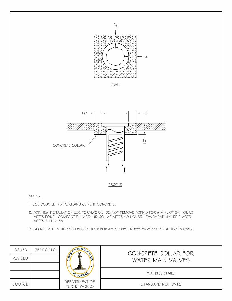
12"
12
"12" 12"
12
"CONCRETE COLLAR
PLAN
PROFILE
NOTES:
1. USE 3000 LB MIX PORTLAND CEMENT CONCRETE.
2. FOR NEW INSTALLATION USE FORMWORK. DO NOT REMOVE FORMS FOR A MIN. OF 24 HOURSAFTER POUR. COMPACT FILL AROUND COLLAR AFTER 48 HOURS. PAVEMENT MAY BE PLACEDAFTER 72 HOURS.
3. DO NOT ALLOW TRAFFIC ON CONCRETE FOR 48 HOURS UNLESS HIGH EARLY ADDITIVE IS USED.
ISSUED SEPT 2012
REVISED
SOURCE DEPARTMENT OFPUBLIC WORKS STANDARD NO. W-15
WATER DETAILS
CONCRETE COLLAR FORWATER MAIN VALVES