chapter 4: practical communication systemsee.ump.edu.my/hazlina/teaching_pcom/chapter4 practical...
TRANSCRIPT

18/09/2016 Nurul/DEE 3413/Practical Com System 1
Chapter 4:
Practical Communication Systems

18/09/2016 Nurul/DEE 3413/Practical Com System 2
Outline
Fibre Optic Communication System
Telephone System
Radio Communication System
Satellite Communication System
Telecommunication Networks

18/09/2016 Nurul/DEE 3413/Practical Com System 3
Outline:
Fibre Optic Communication System
Introduction
Elements in an optical fiber communication link
Propagation mode
Advantages fiber optic cables over conventional electrical cables
Attenuation in fiber optic link
Application of fiber optic system

18/09/2016 Nurul/DEE 3413/Practical Com System 4
Outline:
Telephone system
Introduction
Public telephone network
Telephone connection signalling
Mobile telephone system
Cellular concept
Frequency re-use in cellular
communication

18/09/2016 Nurul/DEE 3413/Practical Com System 5
Outline:
Radio communication System
Introduction
Radio wave propagation
Microwave radio system (analog and digital
microwaves radio transmitters and
receiver)
Radio services

18/09/2016 Nurul/DEE 3413/Practical Com System 6
Outline:
Satellite communication system Introduction
Satellite transponder
Satellite system links
Earth stations
Frequency allocations
Satellite orbit
System performance
Applications of satellite communications
Advantages of satellite system
Disadvantages of satellite system

18/09/2016 Nurul/DEE 3413/Practical Com System 7
Outline:
Telecommunication Networks
Introduction
LAN, MAN and WAN
Network Topology

18/09/2016 Nurul/DEE 3413/Practical Com System 8
Fibre Optic Communication System
Introduction
Fiber optic system is a communication system that
carries information through a guided fiber optic
cable
Light frequencies used in fiber optic systems are
between 1014 and 4x10¹⁴ Hz
Thus, the higher the carrier the carrier frequency,
the wider the bandwidth and consequently, the
greater the information carrying capacity

18/09/2016 Nurul/DEE 3413/Practical Com System 9
Fibre Optic Communication System
Elements in an optical fiber
communication link

18/09/2016 Nurul/DEE 3413/Practical Com System 10
Fibre optic - Basic elements
The main elements are:
Driving circuitry: Serves as an electrical interface between the input circuitry and
light source and to drive the light source
Light source LED / LASER
Convert electrical energy to optical energy, where the amount of light emitted is proportional to the amount of drive current
Light source-to-fiber coupler An interface to couple the light emitted by the source into the
optical fiber cable
Fiber optics Long thin strand of glass or plastic fiber used to signal in a form of
light from a point to another point

18/09/2016 Nurul/DEE 3413/Practical Com System 11
Fiber optics Long thin strand of glass or plastic fiber used to signal in a form of
light from a point to another point
Fiber-to-detector coupler Interface between fiber and light detector to couple as much light as
possible from the fiber cable into the light detector
Light detector PIN (p-type-intrinsic-n-type) diode / an APD (avalance photodiode)
Fibre optic - Basic elements

18/09/2016 Nurul/DEE 3413/Practical Com System 12
Propagation Mode
Monomode fiber (core 8 ~ 12
um)
Only one path for the light to
propagate
along fiber
All light rays follow the same
path down
the cable and take the same
time to
travel the length of the cable
Monomode step-index fiber

18/09/2016 Nurul/DEE 3413/Practical Com System 13
Propagation Mode
Multimode step index fiber (50
~200 um)
More than one path for light
propagate
along fiber
Light ways are propagated
down the cable
in a zig-zag pattern and all the
light rays
do not follow the same path
with
different propagation time
fastest modeslowest mode
input pulse output pulse
Multimode step-index fiber

18/09/2016 Nurul/DEE 3413/Practical Com System 14
Propagation Mode
Multimode graded index fiber
Light is propagated down the
fiber
by refraction which result a
continuous bending at the light
rays,
Then the rays traveling near
the center,
so that all the rays arrive at the
end
point at the same time input pulse output pulse
Multimode graded-index

18/09/2016 Nurul/DEE 3413/Practical Com System 15
Fiber optic - Advantages
Wider bandwidth: have higher information to carry
Lower loss/attenuation: there is less signal attenuation over long distance
Light weight: higher than copper cable and offer good benefit where weight is critical (plane)
Small size: smaller diameter than electrical cable
Strength: as it has cladding, they offer more strength
Security: cannot be ‘tapped’ easily as electrical cable

18/09/2016 Nurul/DEE 3413/Practical Com System 16
Attenuation
The attenuation in fiber optics are due
mainly to:
Scattering losses (kehilangan serakan)
Absorption losses (kehilangan penyerapan)
Bending losses (kehilangan pembengkokan /lenturan)
Splicing loss
Coupling losses (kehilangan gandingan)

18/09/2016 Nurul/DEE 3413/Practical Com System 17
Attenuation – standard fiber
1st window wavelength :0.85 um The lowest minimum loss: 5 to 10 db/km
2nd window 1.30 um 0.5 to 2 dB/km
3rd window 1.55 um 01. to 0.5 dB/km

18/09/2016 Nurul/DEE 3413/Practical Com System 18
Application of fiber optic cable
Some of the applications of fiber optic
Long haul, backbone public and private networks
Local loop networks
Fiber backbone networks (LAN connectivity)
High resolution image and digital video
Computer networks, wide area and local area
Shipboard communications
Aircraft communications and controls
Interconnection of measuring and monitoring instruments in plants and laboratories

18/09/2016 Nurul/DEE 3413/Practical Com System 19
Satellite communication system
Satellite communications utilizes radio frequencies in the
microwave range as the communications medium and uses
satellites to 'bounce' an earth-bound station's uplink signal
back down to a receiving earth station.
A satellite system consist of:
A transponder (a radio repeater in the sky)
A ground-based station to control this operation
A user network of earth stations that provide the facilities for transmission and reception of communication traffics through the satellite station

18/09/2016 Nurul/DEE 3413/Practical Com System 20
The uplink and downlink use different carrier frequencies to avoid interference, and the frequency
translation is done in the transponder.
Satellite communication system

18/09/2016 Nurul/DEE 3413/Practical Com System 21
Satellite transponder
Satellite transponder acts like a repeater,
consists of a receiver and a transmitter. The
main functions of a satellite transponder are:
To pick up the transmitted signal from the
transmission on the earth
To amplify the signal
To translate the carrier frequency to another
frequency
To retransmit the amplified signal to the receiver on
the earth

18/09/2016 Nurul/DEE 3413/Practical Com System 22
Satellite transponder
Earth
station
Earth
station
Band pass
filter
Low noise
Amplifier
(LNA)
Mixer Band pass
filter
(BPF)
Low power
Amplifier
Local
oscillator
Frequency translator
A satellite transponder
BPF – limits the total noise
LNA amplifiers – receive signal and fed it to the frequency translator
Freq. translator – convert the high-band uplink frequency to the low-band downlink frequency

18/09/2016 Nurul/DEE 3413/Practical Com System 23
Satellite system link
Uplink Path of the satellite signal from the earth transmitter to the
receiver of the satellite.
The freq. signal being transmitted from the earth station to the satellite is called uplink frequency
eg: uplink freq. for C-band is 6 Ghz
Downlink Path of the satellite signal from the satellite transmitter to the
receiver on the earth
The retransmitted signal from the satellite to the receiving stations is called the down-link
eg: downlink freq. for C-band is 4 GHz

18/09/2016 Nurul/DEE 3413/Practical Com System 24
Earth station
Baseband in
FDM or
PCM/TDM
Modulator
(FM, PSK or
QAM)
Mixer Band pass
filter
(BPF)
High Power
Amplifier
(HPA)
Generator
Up-Converter
Tel
Data Video
To
Satellite
transponder
AN EARTH STATION TRANSMITTER
Low noise
Amplifier
(LNA)
Demodulator
(FM, PSK
or QAM
Mixer Band pass
filter
(BPF)
Generator
Down-Converter
Baseband out
(FDM or
PCM/TDM) Tel
Data Video
From satellite
transponder
AN EARTH STATION RECEIVER

18/09/2016 Nurul/DEE 3413/Practical Com System 25
Earth station
Baseband in
FDM or
PCM/TDM
Modulator
(FM, PSK or
QAM)
Mixer Band pass
filter
(BPF)
High Power
Amplifier
(HPA)
Generator
Up-Converter
Tel
Data Video
To
Satellite
transponder
AN EARTH STATION TRANSMITTER
- Intermediate freq (IF) modulator converts the input baseband signals
to either an FM, a PSK or a QAM modulated intermediate frequency.
- The up converter converts the IF to an appropriate RF carrier freq.
- The High Power Amplifier (HPA) provides the adequate input
sensitivity and output power to propagate the signal to the satellite
transponder.
18/09/2016 Nurul/DEE 3413/Practical Com System 26
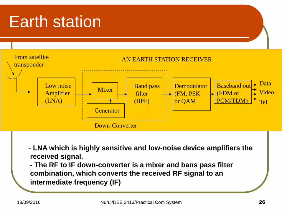
Earth station
Low noise
Amplifier
(LNA)
Demodulator
(FM, PSK
or QAM
Mixer Band pass
filter
(BPF)
Generator
Down-Converter
Baseband out
(FDM or
PCM/TDM) Tel
Data
Video
From satellite
transponder AN EARTH STATION RECEIVER
- LNA which is highly sensitive and low-noise device amplifiers the
received signal.
- The RF to IF down-converter is a mixer and bans pass filter
combination, which converts the received RF signal to an
intermediate frequency (IF)

18/09/2016 Nurul/DEE 3413/Practical Com System 27
Frequency Allocation

18/09/2016 Nurul/DEE 3413/Practical Com System 28
Sattellite Orbits Satellites are launched into orbit, which is to say
that they are shot up into the sky on rockets to get
them up above the atmosphere where there is no
friction. The idea is to get them flying so fast, that
when they fall back to earth, they fall towards earth
at the same rate as the earth's surface falls away
from them. When an object's path around the earth
"trajectory" matches the earth's curvature, the
object is said to be "in orbit".
Satellite Orbit

18/09/2016 Nurul/DEE 3413/Practical Com System 29
Satellite Orbit
Three basic types of orbits are:
1. Polar orbit
North-south orbit
Used for navigation, weather
satellite, meteorological etc
Not used for telecommunication
purposes
2. Elliptically inclined orbit
Used for Russian domestic systems,
with inclination of 63 degrees and a
12 hour orbit period, but visible for
8 hours only
So 3 satellites are needed for
continuous coverage
Basic Orbits

18/09/2016 Nurul/DEE 3413/Practical Com System 30
Satellite Orbit
3) Circular equatorial orbit
It is called geosynchronous orbit
At a height of about 35800 km, has 24 hour orbit period, and its
angular speed is equal to the rotational speed of the earth.
So it appears stationary or motionless over a fixed point on the earth’s surface.
The satellite is visible from 1/3
of the earth’s surface, so 3
satellite are needed for full
coverage of the earth
Basic orbits

18/09/2016 Nurul/DEE 3413/Practical Com System 31
Equatorial
orbit
Polar orbit
Elliptically
inclined
Satellite Orbit

18/09/2016 Nurul/DEE 3413/Practical Com System 32
System performance
Transponder
Gain, Gsat
HPA LNA
Uplink Downlink
Gr Gt
Lp Lp
Pr
Gr Gt
Lf
Pt
Po Pin
Earth station transmitter Earth station receiver
HPA – high power amplifier
Po - HPA output power
Lf - feeder loss
Gt - transmit antenna gain
Lp - path loss
Gr - receive antenna gain
LNA – low noise amplifier
Pt - total radiated power, Pt = Po - Lf
EIRP - Effective Isotropic Radiated Power
EIRP = Pt * Gt

18/09/2016 Nurul/DEE 3413/Practical Com System 33
Uplink And Downlink Chains
The term uplink chain is used to refer to the series of pieces
of equipment that are used to produce a radio frequency
signal for sending out data. The description provided here is
imprecise as the exact configuration can vary widely.
The downlink chain is built using nearly the same equipment
in reverse order.

18/09/2016 Nurul/DEE 3413/Practical Com System 34

18/09/2016 Nurul/DEE 3413/Practical Com System 35
Digital data - modulator ( Intermediate Frequency range (70-140 Mhz)). The modulators use standards such as Digital Video Broadcast to organize communication over the microwave link.
The Intermediate Frequency - "up converter" - a higher frequency
Noise removed - a band pass filter - then amplified.
Signal - transmitted - wave guide to the dish.
The feed horn at the focal point of the dish emits the high frequency radio transmission, which the dish focuses into a directional transmission at the satellite.
Uplink Chains

18/09/2016 Nurul/DEE 3413/Practical Com System 36
The signal is received at the sattellite dish
The signal is amplified and fed to the Down Converter
The Down Converter down mixers the signal to create an intermediate frequency
The intermediate frequency is fed to the demodulator and converted into a data signal
The datastream is forwarded into the network via a router.
Downlink Chains

18/09/2016 Nurul/DEE 3413/Practical Com System 37
Application of satellite communication
Some of the application s of satellite communications are:
Digital audio broadcasting
Television distribution
Serving remote areas
Point-to-multipoint communications
Remote monitoring and control
Vehicle tracking
Mobile communications
Maritime and air navigation
Video teleconferencing

18/09/2016 Nurul/DEE 3413/Practical Com System 38
Advantages/disadvantages of
satellite system
Advantages of a satellite system include:
It can access to wide geographical area
Wide bandwidth
High reliability
Distance sensitive cost
Independent of terrestrial infrastructure
Disadvantages of satellite system
High initial cost
It has propagation delay

18/09/2016 Nurul/DEE 3413/Practical Com System 39
Telecommunication Networks
“A network is a communication system that interconnects many users and is designed to let any user send messages to any and/or all other users on a common set of communication links”
The word network is used generally to mean a set of computers that are connected together in such a way as to permit them to communicate and share information.
Network applications: Offices
Linking various personal computers
Interconnecting larger computers located in different buildings or cities etc.

18/09/2016 Nurul/DEE 3413/Practical Com System 40
LAN, MAN and WAN
Three categories of networking depends on the
application: LAN, MAN and WAN
LAN (Local Area Networks)
MAN (Metropolitan Area Networks)
WAN (Wide Area Networks)

18/09/2016 Nurul/DEE 3413/Practical Com System 41
LAN
Is a data communication network across a limited
area, at most 5 km
Permit the users (normally 10 – 100 users) to share
information and computers sources include data
storage, software, printer, etc
Is used to connect several offices within the same
building, or in a working group or as a campus
backbone

18/09/2016 Nurul/DEE 3413/Practical Com System 42
MAN
Medium- sized network
Cover an area between 5 – 50 km
Typically MAN may use coaxial cables or optical fiber as the medium
Provide services such as audio, data and video
High capacity backbone (1.544 Mbps or 45 Mbps)

18/09/2016 Nurul/DEE 3413/Practical Com System 43
WAN
Cover a large area, more than 50 km
Typically, WAN is a packet switching network
Used in internet, electronic mail, airline reservation system
In some cases, WAN is built of smaller LANs that are closely linked, or made of mixed combinations of LANs and special longer distance links
Connect computers located over large geographical areas through some combination of telephone lines, satellite, radio transmission and optical fiber over public switched telephone network (PSTN) or private network facilities

18/09/2016 Nurul/DEE 3413/Practical Com System 44
Network Topology
Network topology is a physical schematic for the different configuration or arrangements, to show the interconnection of the users
The logical topology concerns signal flow in the network or how data actually travels
There are 3 basic topologies: Star network topology
Ring network topology
Bus network topology

18/09/2016 Nurul/DEE 3413/Practical Com System 45
Ring network topology
users - connected in closed path
token-passing ring protocol - predictable access time to the network
Ring scheme node accepts the message- processes - extracts data -modifies
message - passes it on to the next node
A drawback of the ring The failure of any node - cause breakdown over come by :
Dual or redundant path as a standby path
Watchdog circuitry: When it detect a problem with the node, it sets a switch which electrically by-passes that node

18/09/2016 Nurul/DEE 3413/Practical Com System 46
Bus network topology
all user nodes - connected
by a bus - a coaxial cable
or parallel-wire line
The signals can move in
both directions along the
bus
Advantage - use a single path - saves cost
Drawback – rewiring difficulty - complicated protocols – CSMA/CD (carrier sense multiple access/collision detect)

18/09/2016 Nurul/DEE 3413/Practical Com System 47
Star network topology
all user nodes - connected
to a central hub
The signals are sent to
central point
Advantage – expanding flexibility
Drawback – slow – need to go through central hub

18/09/2016 Nurul/DEE 3413/Practical Com System 48

18/09/2016 Nurul/DEE 3413/Practical Com System 49
Local Area Network Topologies
Local Area Networks (LANs) use one of the following
designs. These designs are referred to as 'topologies'.

18/09/2016 Nurul/DEE 3413/Practical Com System 50
18/09/2016 Nurul/DEE 3413/Practical Com System 51
Example:
1. A satellite transponder has a gain of 50 dB. Its
receiving and transmitting antenna have equal gain of
20 dB. If the receiving antenna receives a signal
power of 10 uW from the earth transmitter, determine
the signal power at the output of the satellite
transmitting antenna.

18/09/2016 Nurul/DEE 3413/Practical Com System 52
Telephone
Telephone system
Public telephone network
- Local loop or local network
- Junction network
- Trunk network or toll network
- # international gateway
Telephone connection signalling
- Speech signal/information signal (in analogue form)
- Control signal (in analogue or digital form)
- Dialling tone
- Ringing tone
- Busy tone

18/09/2016 Nurul/DEE 3413/Practical Com System 53
Mobile telephone system
Mobile set (handset)
Radio base station (RBS)
Mobile switching centre (MSC)
Cellular concept
Frequency re-use in cellular communication
Telephone
18/09/2016 Nurul/DEE 3413/Practical Com System 54
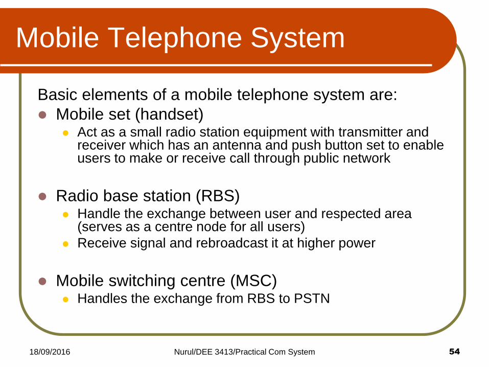
Mobile Telephone System
Basic elements of a mobile telephone system are:
Mobile set (handset) Act as a small radio station equipment with transmitter and
receiver which has an antenna and push button set to enable users to make or receive call through public network
Radio base station (RBS) Handle the exchange between user and respected area
(serves as a centre node for all users)
Receive signal and rebroadcast it at higher power
Mobile switching centre (MSC) Handles the exchange from RBS to PSTN

18/09/2016 Nurul/DEE 3413/Practical Com System 55
Mobile Telephone System

18/09/2016 Nurul/DEE 3413/Practical Com System 56
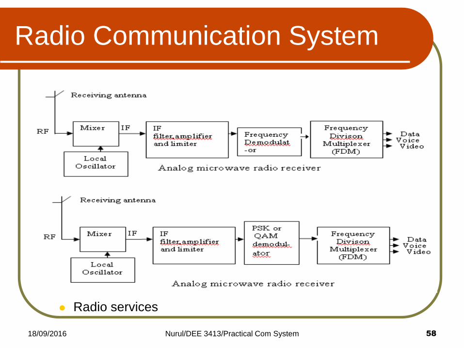
Radio Communication System
Radio communication System Introduction
- Is a wireless communication system by using the propagation of electromagnetic signals through free-space
- Two categories of radio systems:
- Conventional AM or FM radio
- Digital radio system
- In digital radio system, the modulating and demodulated signals are digital pulses.
- Three digital modulation techniques that are commonly used in digital radio systems:
- FSK, PSK and QAM
Radio wave propagation - Ground wave : low freq (LF) and medium freq (MF) bands
- Space wave: VHF, UHF and higher freq bands
- Sky wave: MF and HF bands

18/09/2016 Nurul/DEE 3413/Practical Com System 57
Microwave radio system (analogue and digital microwaves
radio transmitters and receiver)
The main difference is the modulation technique used and the multiplexing technique
Radio Communication System
18/09/2016 Nurul/DEE 3413/Practical Com System 58
Radio services
Radio Communication System