chapter 9 radio wave...
TRANSCRIPT

Antenna & Propagation Radio Wave Propagation
1
Chapter 9 – Radio Wave Propagations
9.1 Definition of Path Loss
9.2 Rays and wavefront
9.3 Characteristic Impedance of Free Space
9.4 Critical Frequency and Critical Angle, Virtual Height, Maximum
usable Frequency, Skip Distance and Skip Zone
9.5 Free Space Path Loss
9.6 Fading and Fade Margin
9.7 Friis transmission formula
9.8 Concept of Ground, Sky and Space wave

Antenna & Propagation Radio Wave Propagation
2
Introduction to Radio Wave Propagation
• Electromagnetic wave propagation
– reflection
– diffraction
– scattering
• Urban areas
– No direct line-of-sight
– high-rise buildings causes severe diffraction loss
– multipath fading due to different paths of varying lengths
• Large-scale propagation models predict the mean signal strength for an arbitrary T-R separation distance.
• Small-scale (fading) models characterize the rapid fluctuations of the received signal strength over very short travel distance or short time duration.

Antenna & Propagation Radio Wave Propagation
3
• Small-scale fading: rapidly fluctuation
– sum of many contributions from different directions with different phases
– random phases cause the sum varying widely. (ex: Rayleigh fading
distribution)
• Local average received power is predicted by large-scale model
(measurement track of 5 to 40 )

Antenna & Propagation Radio Wave Propagation
4
Free Space Propagation Model • The free space propagation model is used to predict received signal
strength when the transmitter and receiver have a clear line-of-sight path between them.
– satellite communication
– microwave line-of-sight radio link
• Friis free space equation

Antenna & Propagation Radio Wave Propagation
5
• The gain of the antenna
: effective aperture is related to the physical size of the antenna
• The wave length is related to the carrier frequency by
: carrier frequency in Hertz
: carrier frequency in radians
: speed of light (meters/s)
• The losses are usually due to transmission line attenuation, filter losses, and antenna losses in the communication system. A value of L=1 indicates no loss in the system hardware.
2
4
eAG
eA
c
c
f
c
2
f
c
c
L )1( L

Antenna & Propagation Radio Wave Propagation
6
• Isotropic radiator is an ideal antenna which radiates power with unit gain.
• Effective isotropic radiated power (EIRP) is defined as
and represents the maximum radiated power available from transmitter in the direction of maximum antenna gain as compared to an isotropic radiator.
• Path loss for the free space model with antenna gains
• When antenna gains are excluded
• The Friis free space model is only a valid predictor for for values of d which is in the far-field (Fraunhofer region) of the transmission antenna.
ttGPEIRP
22
2
)4(log10log10)(
d
GG
P
PdBPL rt
r
t
22
2
)4(log10log10)(
dP
PdBPL
r
t
rP

Antenna & Propagation Radio Wave Propagation
7
• The far-field region of a transmitting antenna is defined as the region beyond the far-field distance
where D is the largest physical linear dimension of the antenna.
• To be in the far-filed region the following equations must be satisfied
and
• Furthermore the following equation does not hold for d=0.
• Use close-in distance and a known received power at that point
or
22Dd f
Dd f fd
Ld
GGPdP rtt
r 22
2
)4()(
0d )( 0dPr2
00)()(
d
ddPdP rr fddd 0
d
ddPdP r
r00 log20
W 001.0
)(log10dBm )( fddd 0

Antenna & Propagation Radio Wave Propagation
8
RAYS & WAVE FRONT
• Rays are used to show the relative direction of electromagnetic wave propagation.
• A ray is a line drawn along the direction of propagation of an electromagnetic wave.
• However, a ray does not necessarily represent the propagation of a single electromagnetic wave.

Antenna & Propagation Radio Wave Propagation
9
RAYS & WAVE FRONT
• A wavefront shows a surface of a constant phase of a wave.
• A wavefront is formed when points of equal phase on rays propagated from the same source are joined together.
• When a surface is plane, its wavefront is perpendicular to the direction of propagation.
• The closer to the source, the more complicated the wavefront becomes.

Antenna & Propagation Radio Wave Propagation
10
RAYS & WAVE FRONT
Plane wave
Wavefront from a point source

Antenna & Propagation Radio Wave Propagation
11
RAYS & WAVE FRONT

Antenna & Propagation Radio Wave Propagation
12
CHARACTERISTIC IMPEDANCE OF FREE SPACE
• The electric and magnetic field intensities of an electromagnetic wave in free space are related though the characteristic impedance (resistance) of free space.
377
1085.8
1026.112
6
0
0
SZ

Antenna & Propagation Radio Wave Propagation
13
PATH LOSS
• Antenna gain related to effective area:
2
4
AG
22
21
2
214
R
AA
RGG
P
P
t
d
A = antenna aperture
G = antenna gain
R = distance (km)
Pd = Power delivered
Pt = Power received

Antenna & Propagation Radio Wave Propagation
14
PATH LOSS
• The path loss:
dBGdBGRfKdBlossPath U 21log20)(_
Unit KU
km 32.45
nm 37.80
miles 36.58
m -27.55
ft -37.87
R in (km), f in (MHz)
While KU depends on the length units:

Antenna & Propagation Radio Wave Propagation
15
ATTENUATION
• As a wavefront moves away from the source, the continuous electromagnetic field that is radiated from that source spreads out.
• That is, the waves move farther away form each other and consequently, the number of waves per unit area decreases.
• None of the radiated power is lost or dissipated because the wavefront is moving away from the source.
• The wave simply spreads out or disperses over a larger area, decreasing the power density.
• The reduction in power density with distance is equivalent to a power loss and is commonly called wave attenuation.
• The attenuation is due to the spherical spreading of the wave, it is sometimes called space attenuation of the wave.

Antenna & Propagation Radio Wave Propagation
16
ABSORPTION
• The reduction in power density due to non-free space propagation called absorption.
• Absorption of radio frequencies in a normal atmosphere depends on frequency and is relatively significant below approximately 10 Ghz.
Atmospheric absorption of electromagnetic waves.
Antenna & Propagation Radio Wave Propagation
17
The Three Basic Propagation Mechanisms
• Basic propagation mechanisms
– reflection
– diffraction
– scattering
• Reflection occurs when a propagating electromagnetic wave impinges upon an object which has very large dimensions when compared to the wavelength, e.g., buildings, walls.
• Diffraction occurs when the radio path between the transmitter and receiver is obstructed by a surface that has sharp edges.
• Scattering occurs when the medium through which the wave travels consists of objects with dimensions that are small compared to the wavelength.

Antenna & Propagation Radio Wave Propagation
18
• Reflection from dielectrics
• Reflection from perfect conductors
– E-field in the plane of incidence
– E-field normal to the plane of incidence
riri EE and
riri EE and

Antenna & Propagation Radio Wave Propagation
19
• Ground Reflection (2-ray) Model

Antenna & Propagation Radio Wave Propagation
20
• Diffraction

Antenna & Propagation Radio Wave Propagation
21
• The actual received signal is often stronger than what is predicted by
reflection and diffraction
• Scattering
– when a radio wave impinges on a rough surface, the reflected energy is
spread out, e.g., trees, lamp posts.
• Surface roughness is test using Rayleigh criterion which defines a
critical height for a given angle of incidence
ch i
i
ch
sin8
rough surface
ch
smooth surface
ch

Antenna & Propagation Radio Wave Propagation
22
INTERFERENCE
• Interference means to come into opposition
• Interference is the act of interfering
• Radio-wave interference occurs when two or more electromagnetic waves combine in such a way that system performance is degraded.
• Interference also refer to the principles of linear superposition of electromagnetic waves and occurs whenever two or more waves simultaneously occupy the same point in the space.

Antenna & Propagation Radio Wave Propagation
23
INTERFERENCE
Electromagnetic wave distribution [Huygen’s principles for a plane wavefront]

Antenna & Propagation Radio Wave Propagation
24
INTERFERENCE
Electromagnetic wave distribution [finite wavefront through a slot]

Antenna & Propagation Radio Wave Propagation
25
INTERFERENCE
Electromagnetic wave distribution [around an edge]

Antenna & Propagation Radio Wave Propagation
26
INTERFERENCE
Linear addition of two vectors with differing phase angles
Electromagnetic wave interference

Antenna & Propagation Radio Wave Propagation
27
TERRESTRIAL PROPAGATION
• Electromagnetic wave traveling within Earth’s atmosphere are called terrestrial waves.
• Communication between two or more points on Earth is called terrestrial radio communication.
• Terrestrial waves are influenced by the atmosphere and Earth itself.
• Three ways of propagating electromagnetic waves within Earth’s atmosphere: ground wave, space wave and sky wave propagation.

Antenna & Propagation Radio Wave Propagation
28
TERRESTRIAL PROPAGATION
Normal modes of wave propagation
Antenna & Propagation Radio Wave Propagation
29
SURFACE WAVE PROPAGATION
• A surface wave is an Earth-guided electromagnetic wave that travels over the surface of Earth.
• As a surface wave move over Earth’s surface, it is accompanied by charge induced in the Earth.
• The charges move with the wave, producing a current.
• The Earth offers resistance to the flow current, energy is dissipated in a manner very similar to those in transmission line.
• The surface waves are attenuated by dielectric losses of Earth’s surface.
• The energy is replenished by diffraction of energy downward from the portions of the ground wave immediately above Earth’s surface.

Antenna & Propagation Radio Wave Propagation
30
SURFACE WAVE PROPAGATION
Surfaces waves propagation

Antenna & Propagation Radio Wave Propagation
31
Space Wave Propagation
Space waves propagation

Antenna & Propagation Radio Wave Propagation
32
SPACE WAVE PROPAGATION • Space wave propagation of electromagnetic energy includes
radiated energy that travels in the lower few miles of the atmosphere.
• Space waves include both direct and ground reflected wave as shown in Fig. 7.16.
• Direct waves travel essentially in a straight line between the transmit and receive antennas.
• Space wave propagation with direct waves in commonly called line of sight (LOS) transmission.
• Therefore, direct space wave propagation is limited by the curvature of the Earth.
• Ground-reflected waves are waves reflected by Earth’s surface as they propagate between the transmit and receive antennas.

Antenna & Propagation Radio Wave Propagation
33
SPACE WAVE PROPAGATION
Space waves and radio horizon
Antenna & Propagation Radio Wave Propagation
34
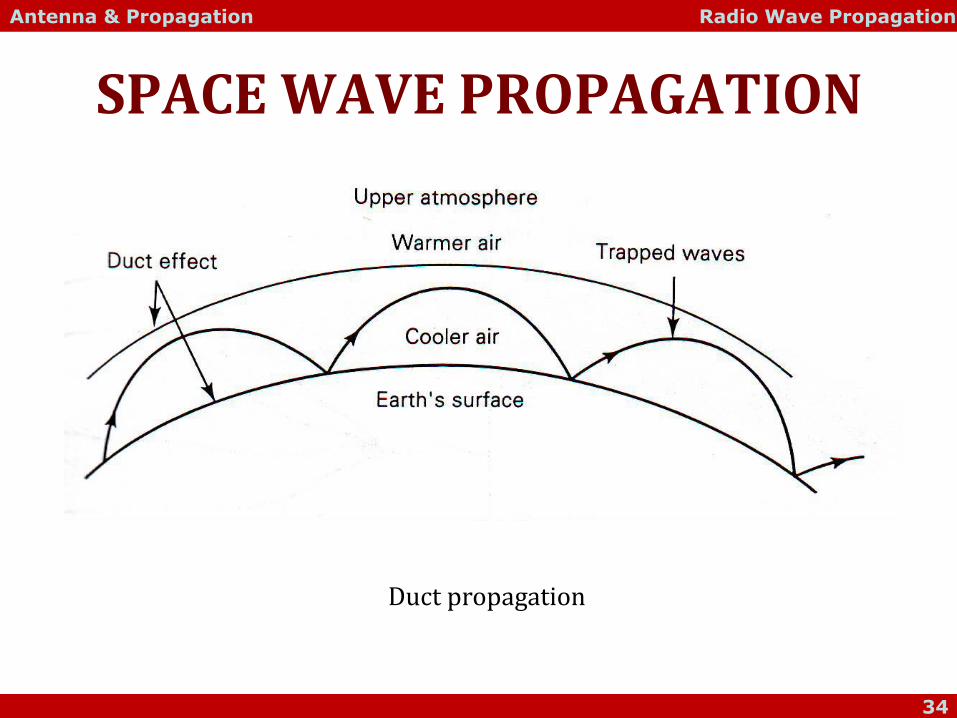
SPACE WAVE PROPAGATION
Duct propagation

Antenna & Propagation Radio Wave Propagation
35
SPACE WAVE PROPAGATION
• The curvature of Earth presents a horizon to space wave propagation commonly called radio horizon.
• The radio horizon extends beyond the optical horizon for the common standard atmosphere.
• The radio horizon is approximately four-thirds that of the optical horizon.
• Refraction is caused by the troposphere because of changes in its density, temperature, water vapor content and relative conductivity.
• The radio horizon can be lengthened simply by elevating the transmit or receive antennas (or both) above Earth’s surface with towers or by placing them on top of mountains or high buildings.

Antenna & Propagation Radio Wave Propagation
36
SPACE WAVE PROPAGATION
hd 2
rt
rt
hhd
ddd
22
d = distance to radio horizon (miles)
h = antenna height above sea level (feet)
d = total distance (miles)
dt = radio horizon for transmit antenna (miles)
dr = radio horizon for receive antenna (miles)
ht = transmit antenna height (feet)
hr = receive antenna height (feet)

Antenna & Propagation Radio Wave Propagation
37
SPACE WAVE PROPAGATION
rt hhd 1717(max)
d(max) = maximum distance between transmitter and receiver (km) ht = height of transmit antenna above sea level (m) hr = height of receive antenna above sea level (m)

Antenna & Propagation Radio Wave Propagation
38
SKY WAVE PROPAGATION
• Electromagnetic waves that are directed above the horizon level are called sky waves.
• Typically, sky wave are radiated in a direction that produces a relatively large angle with reference to Earth.
• Sky waves are radiated toward the sky, where they are either reflect or refracted back to Earth by the ionosphere.
• The ionosphere is the region of space located approximately 50 -400 km above the Earth’s surface.
• The ionosphere layer absorbs large quantities of the sun’s radiant energy, which ionizes the air molecules and creating free electron.

Antenna & Propagation Radio Wave Propagation
39
SKY WAVE PROPAGATION
Ionospheric layer

Antenna & Propagation Radio Wave Propagation
40
SKY WAVE PROPAGATION • When, a radio wave passes through the ionosphere, the electric
field of the wave exerts a force on the free electrons, causing them to vibrate.
• The vibrating electrons decrease current, which is equivalent to reducing the dielectric constant.
• Reducing the dielectric constant increases the velocity of propagation and causes electromagnetic waves to bend away from the regions of high electron density toward regions of lower density.
• As the wave moves farther from Earth, ionization increases; however, there are fewer air molecules to ionize.
• Therefore, the upper ionosphere has a higher percentage of ionized molecules than the lower atmosphere.
• The higher the ion density, the more refraction.

Antenna & Propagation Radio Wave Propagation
41
SKY WAVE PROPAGATION
• D Layer
– The lowest layer of the ionosphere and is located approximately between 50-100 km above the Earth’s surface.
– Little ionization.
– Very little effect on the direction of propagation of radio waves.
– The amount of ionization in D layer depends on the altitude of the sun above the horizon.
– Disappears at night.
– Reflects VLF and LF waves and absorb MF and HF waves.

Antenna & Propagation Radio Wave Propagation
42
SKY WAVE PROPAGATION
• E Layer
– 100-140 km above Earth’s surface.
– Also called as Kennelly-heaviside layer.
– Maximum density at approximately 70 miles at noon, when the sun is at its highest point.
– Totally disappears at night.
– Aids MF surface wave propagation and reflects HF waves during daytime.

Antenna & Propagation Radio Wave Propagation
43
SKY WAVE PROPAGATION
• F Layer
– Made up of two layers, the F1 and F2 layers.
– Daytime: the F1 layer is located at 140-250 km above the Earth’s surface; the F2 layer 140-300 km (250-350 km during winter).
– Night: the F1 layer combines with the F2 layer to form a single layer.
– The F1 layer absorbs and attenuates some HF waves, although most of the waves pass through to the F2 layer, where they will reflect back to Earth.

Antenna & Propagation Radio Wave Propagation
44
CRITICAL FREQUENCY & CRITICAL ANGLE
• Critical frequency (fc) is defined as the highest frequency that can be propagated directly upward and still be returned to Earth by the ionosphere.
• fc is depends on the ionization density and therefore varies with the time of day and the season.
• If the vertical angle of radiation is decreased, frequency at or above the fc can still be refracted back to Earth’s surface because they will travel a longer distance in the ionosphere and thus, have a longer time to be refracted.
• Every frequency has a maximum vertical angle at which it can be propagated and still can be refracted back by the ionosphere. This is called critical angle.

Antenna & Propagation Radio Wave Propagation
45
CRITICAL FREQUENCY & CRITICAL ANGLE
critical angle

Antenna & Propagation Radio Wave Propagation
46
VIRTUAL HEIGHT
virtual height

Antenna & Propagation Radio Wave Propagation
47
VIRTUAL HEIGHT
• Virtual height is the height above Earth’s surface from which a refracted wave appears to have been reflected.
• The radiated wave is refracted back to Earth and follows path B.
• The actual maximum height that the wave reached is height ha. However, path A shows the projected path that a reflected wave could have taken and still be returned to Earth at the same location.
• The maximum height that this hypothetical reflected wave would have reached is the virtual height (hv).

Antenna & Propagation Radio Wave Propagation
48
MAXIMUM USABLE FREQUENCY
• The maximum usable frequency (MUF) is the highest frequency that can be used for sky wave propagation between two specific points on Earth’s surface. ic
i
c
f
fMUF
sec
cos
θi= angle of incident

Antenna & Propagation Radio Wave Propagation
49
SKIP DISTANCE & SKIP ZONE
• Skip distance (ds) is defined as the minimum distance from a transmit antenna that a sky wave at a given frequency will be returned to Earth.
• The frequency must be less than the MUF and propagated at critical frequency.
• When the radiation angle (θr) exceeds the critical angle (θc), the waves penetrates the ionosphere and escapes Earth’s atmosphere.

Antenna & Propagation Radio Wave Propagation
50
SKIP DISTANCE & SKIP ZONE
skip distance

Antenna & Propagation Radio Wave Propagation
51
SKIP DISTANCE & SKIP ZONE
day time versus night time propagation

Antenna & Propagation Radio Wave Propagation
52
FREE SPACE PATH LOSS
• Free space path loss is often defined as the loss incurred by an electromagnetic wave as it propagates in a straight line through a vacuum with no absorption or reflection of energy from the nearby objects.
• Free space path loss is a misstated and often misleading definition because no energy is actually dissipated.
• Free space path loss is a fabricated engineering quantity that evolved from manipulating communications system link budget equations into a particular format.

Antenna & Propagation Radio Wave Propagation
53
FREE SPACE PATH LOSS
24
DLp
kmGHzp
kmMHzp
DfdBL
DfdBL
log20log204.92
log20log204.32
Lp = free space path loss D = distance (km) f = frequency (Hz) λ = wavelength (m) c = velocity of light