chapter 4: lida fact sheetscleanwaterservices.org/media/1823/lida-handbook-ch-4.pdfinfiltrates...
TRANSCRIPT

20 Low Impact Development Approaches Handbook
These fact sheets provide example photos, design layout sketches, use and design criteria, planting and maintenance information for the types of LIDAs allowed by District Standards. Table 2 lists the fact sheet content and whether to use the LIDA sizing form for a particular LIDA.
LIDA Fact Sheet
The LIDA fact sheets provide example photos, design layout sketches, use and design criteria, planting and maintenance information.
FACT SHEET TITLE CONTENTS USE LIDA SIZING FORM?
Porous Pavement Impervious area reduction using porous pavers, pervious asphalt or concrete
Yes
Green Roof Impervious area reduction using green roof technology, for roofs with 1:3 pitch or flatter
Yes
InfiltrationPlanter/Rain Garden
Planters, rain gardens, vegetated infiltration basins, for native soils with adequate infiltration
Yes
Flow-Through Planter
Planters for low infiltration soils or next to buildings,with liner as needed
Yes
LIDA Swale Short swales for street-side, parking lots, landscaping
Yes
Vegetated Filter Strip
Landscaped areas designed to receive distributed flow from impervious surfaces
Yes
Vegetated Swale District water quality facility for larger drainage areas, minimum 100 foot length
No
Extended Dry Basin District water quality facility for larger drainage areas, 2-cell design, 48-hour draw-down
No
Constructed Water Quality Wetland
District water quality facility for larger drainage areas, 2-cell design with permanent pool
No
Conveyance and Stormwater Art
Ideas for integrating LIDAs and related stormwater conveyance facilities into landscape, hardscape for aesthetics
n/a
Planting Design & Habitat
Plant selection criteria for LIDAs, including ideas for urban habitat creation
n/a
Table 2: LIDA Fact Sheet Table
Chapter 4: LIDA Fact Sheets

Low Impact Development Approaches Handbook 21

22 Low Impact Development Approaches Handbook
Porous Pavement
DescriptionPorous pavement is a water-permeable structural groundcover that infiltrates precipitation, attenuates stormwater runoff flows and volumes, and reduces temperatures. Porous pavement provides a stable load-bearing surface without increasing a project’s total impervious area.
The two main categories of porous pavements are 1) pervious concrete and asphalt, and 2) permeable pavers. Pervious concrete and asphalt are poured in place and resemble their solid counterparts, except the fines (sand and finer material) are removed to create more void space for water to flow through. Permeable pavers are solid, discrete units typically made of pre-cast concrete, brick, stone, or cobbles and set to allow water to flow between them.
parking areas & impermeable landscape
impermeablesoils
Application & LimitationsPorous pavement is not considered a water quality facility to provide treatment of runoff from other impervious surfaces. However, pollutants
Page 1 of 4
Sloped to Drain
permeablesoils
captured from direct rainfall on the porous pavement area are treated through filtration, absorption, and other microbial degradation actions in the subgrade. Porous pavement area may be considered 100% pervious in water quality calculations, thus reducing the size of required water quality facilities.
Pervious asphalt, pervious concrete, and permeable pavers can be used in most pedestrian areas, residential driveways, public sidewalks, and parking lots. Local jurisdictions may approve pervious asphalt and concrete for private streets and public roadways on a case-by-case basis.
Porous pavements should not be located over cisterns, utility vaults, underground parking or other impervious surfaces and should be applied only where the seasonal high water table is at least 10 feet beneath the facility’s bottom or drain rock layer. Porous pavement should not be applied in locations where there is a high risk of chemical spillage.
Porous asphalt surfacePerforated drain pipe (as needed)Choker course
Drain rock (depth varies per design)
Outfall pipe (as needed)
Non-woven geotextile fabricSubgrade
(overflow)
(storage and infiltration)
Low Impact Development Approaches Handbook 23
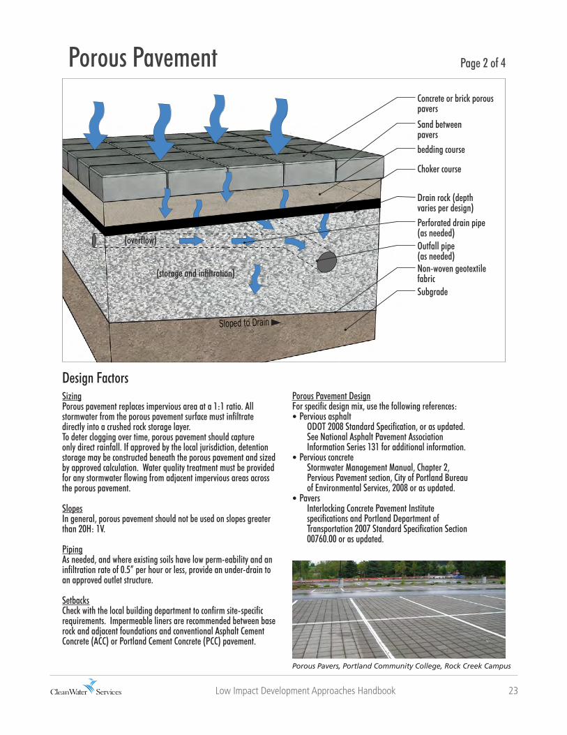
Porous Pavement DesignFor specific design mix, use the following references:• Pervious asphalt ODOT 2008 Standard Specification, or as updated. See National Asphalt Pavement Association Information Series 131 for additional information.• Pervious concrete Stormwater Management Manual, Chapter 2, Pervious Pavement section, City of Portland Bureau of Environmental Services, 2008 or as updated.• Pavers Interlocking Concrete Pavement Institute specifications and Portland Department of Transportation 2007 Standard Specification Section 00760.00 or as updated.
Design FactorsSizingPorous pavement replaces impervious area at a 1:1 ratio. All stormwater from the porous pavement surface must infiltrate directly into a crushed rock storage layer.To deter clogging over time, porous pavement should capture only direct rainfall. If approved by the local jurisdiction, detention storage may be constructed beneath the porous pavement and sized by approved calculation. Water quality treatment must be provided for any stormwater flowing from adjacent impervious areas across the porous pavement.
SlopesIn general, porous pavement should not be used on slopes greater than 20H: 1V.
PipingAs needed, and where existing soils have low perm-eability and an infiltration rate of 0.5” per hour or less, provide an under-drain to an approved outlet structure.
SetbacksCheck with the local building department to confirm site-specific requirements. Impermeable liners are recommended between base rock and adjacent foundations and conventional Asphalt Cement Concrete (ACC) or Portland Cement Concrete (PCC) pavement.
Porous Pavers, Portland Community College, Rock Creek Campus
Porous Pavement Page 2 of 4
Sloped to Drain
Concrete or brick porous pavers
Sand between paversbedding course
Drain rock (depth varies per design)
Outfall pipe (as needed)Non-woven geotextile fabricSubgrade
Perforated drain pipe(as needed)
Choker course
(overflow)
(storage and infiltration)
24 Low Impact Development Approaches Handbook
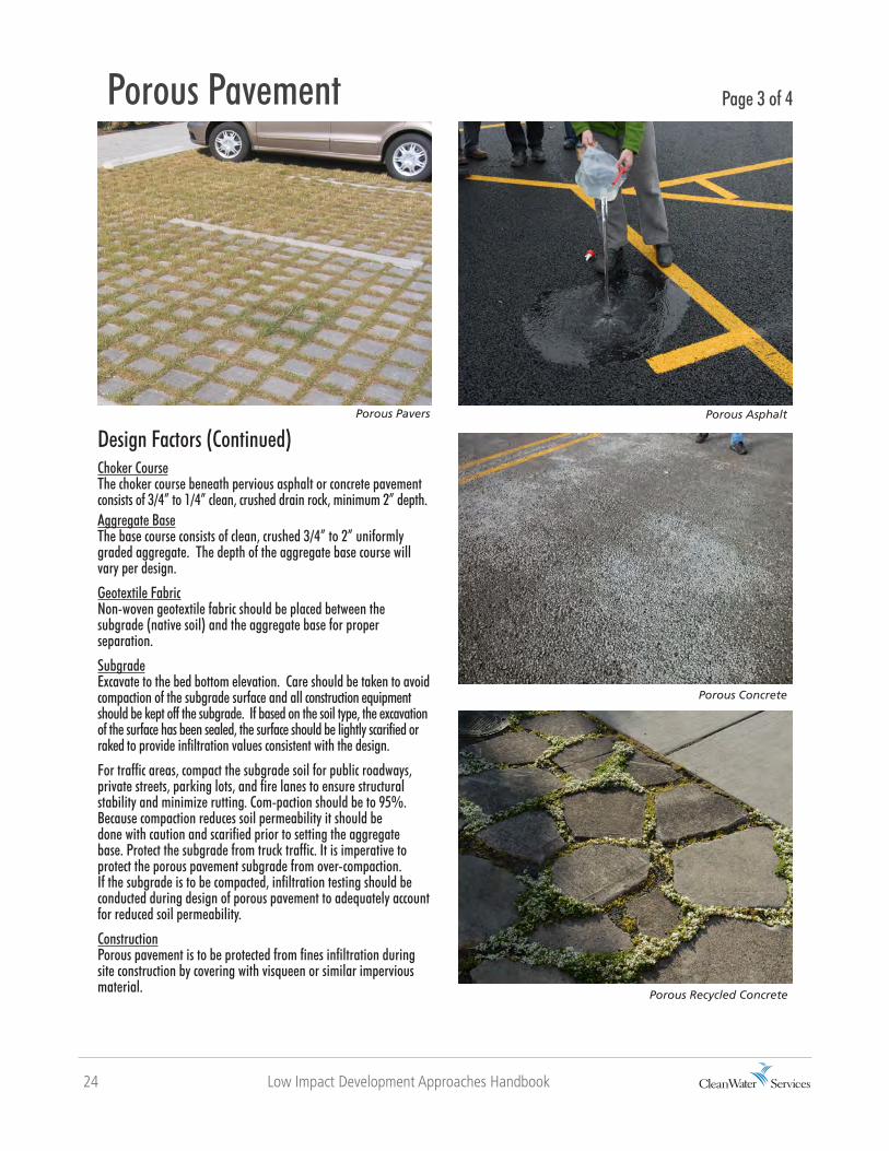
Design Factors (Continued)Choker CourseThe choker course beneath pervious asphalt or concrete pavement consists of 3/4” to 1/4” clean, crushed drain rock, minimum 2” depth.Aggregate BaseThe base course consists of clean, crushed 3/4” to 2” uniformly graded aggregate. The depth of the aggregate base course will vary per design.
Geotextile FabricNon-woven geotextile fabric should be placed between the subgrade (native soil) and the aggregate base for proper separation.
SubgradeExcavate to the bed bottom elevation. Care should be taken to avoid compaction of the subgrade surface and all construction equipment should be kept off the subgrade. If based on the soil type, the excavation of the surface has been sealed, the surface should be lightly scarified or raked to provide infiltration values consistent with the design.
For traffic areas, compact the subgrade soil for public roadways, private streets, parking lots, and fire lanes to ensure structural stability and minimize rutting. Com-paction should be to 95%. Because compaction reduces soil permeability it should be done with caution and scarified prior to setting the aggregate base. Protect the subgrade from truck traffic. It is imperative to protect the porous pavement subgrade from over-compaction. If the subgrade is to be compacted, infiltration testing should be conducted during design of porous pavement to adequately account for reduced soil permeability.
ConstructionPorous pavement is to be protected from fines infiltration during site construction by covering with visqueen or similar impervious material.
Porous Pavers
Porous Recycled Concrete
RiverEast Center
Porous Pavement Page 3 of 4
Porous Asphalt
Porous Concrete
Low Impact Development Approaches Handbook 25
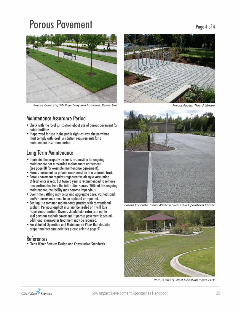
Porous Pavers, Tigard Library
Porous Pavers, West Linn Willamette Park
RiverEast Center
Porous Pavement Page 4 of 4
Porous Concrete, Clean Water Services Field Operations Center
Porous Concrete, SW Broadway and Lombard, Beaverton
Maintenance Assurance Period• Check with the local jurisdiction about use of porous pavement for public facilities.• If approved for use in the public right-of-way, the permittee must comply with local jurisdiction requirements for a maintenance assurance period.
Long Term Maintenance• If private, the property owner is responsible for ongoing maintenance per a recorded maintenance agreement (see page 88 for example maintenance agreement). • Porous pavement on private roads must be in a separate tract.• Porous pavement requires regenerative air style vacuuming at least once a year, but twice a year is recommended to remove fine particulates from the infiltration spaces. Without this ongoing maintenance, the facility may become impervious. • Over time, settling may occur and aggregate base, washed sand, and/or pavers may need to be replaced or repaired.• Sealing is a common maintenance practice with conventional asphalt. Pervious asphalt must not be sealed or it will lose its pervious function. Owners should take extra care not to seal pervious asphalt pavement. If porous pavement is sealed, additional stormwater treatment may be required.• For detailed Operation and Maintenance Plans that describe proper maintenance activities please refer to page 91.
References• Clean Water Services Design and Construction Standards

26 Low Impact Development Approaches Handbook
Green Roof
DescriptionA green roof (or ecoroof) is a lightweight vegetated roof system with waterproofing material, drainage, growing medium, and specially selected plants. A green roof can reduce site impervious area and manage stormwater runoff. Green roofs reduce peak runoff to near pre-development rates and reduce annual runoff volume by at least 50% (Cost Benefit Evaluation of Ecoroofs, Portland Bureau of Environmental Services, 2008). Green roofs also help mitigate runoff temperatures by keeping roofs cool and retaining most of the runoff in dry seasons. Green roofs typically have thin layers of lightweight growing medium (4 to 8 inches) and low-growing succulent vegetation. Alternatively, roof gardens that are designed to be walked on have deeper soils (8+ inches) and are more heavily planted. Professional design consultation may be necessary to ensure the structural requirements of building codes are met. The design must be low maintenance and use irrigation only to sustain the health of vegetation.
buildings
Page 1 of 4
Clean Water Services Field Operations
Application & LimitationsGreen roofs may be considered 100% pervious in water quality calculations, thus reducing the size of water quality facilities. Green roofs can be applied to a range of building types, from ‘flat’ rooftops (minimum of 1/4” slope per foot) to sloped rooftops with up to 4:12 pitch (3H:1V slope) or higher with adequate slope control. Depending on configuration and structure of the roof, the vegetated area may be partial or 100% coverage. The structural roof support must hold the additional weight of the green roof. Greater flexibility and options are available for new buildings, but retrofits are possible. For retrofit projects, an architect, structural engineer, or roof consultant can determine the condition of the existing building structure and what might be needed to support a green roof. Generally, the building structure must hold an additional 15 to 30 pounds per square foot for saturated weight.

Low Impact Development Approaches Handbook 27
Ballast (optional)Gravel ballast may be placed along the roof perimeter and at air vents or other vertical elements to separate roofing elements and vegetation. The need for ballast depends on the type of roof and rooftop flashing details. Ballast or rooftop pavers may be used to provide access, especially to vertical elements that require maintenance.
Header/separation board (optional)If needed, a header or separation board may be placed between gravel ballast and soil or drains.
Root barrierA root barrier may be required, depending on the waterproofing material, warranty requirements, and the types of vegetation proposed. Root barriers impregnated with pesticides, metals, or other chemicals that could leach into stormwater should not be applied unless documentation that leaching does not occur is provided. If a root barrier is used it must extend under any gravel ballast and the growing medium, and up the side of any vertical elements.
Design FactorsSizingGreen roofs replace impervious area at a 1:1 ratio. They may not receive water from other impervious areas such as an adjacent conventional roof.
SlopeMaximum roof pitch is 4:12 (3H:1V slope) unless the applicant provides documentation of runoff retention and erosion control on steeper slopes.
WaterproofingOn the roof surface, use a good waterproofing material such as modified asphalt, synthetic rubber, or reinforced thermal plastics. Waterproofing materials also may act as a root barrier. Waterproof membranes should be thoroughly tested to identify and remedy potential defects and leaks prior to installation of any green roof components.
Protection boards or materials (recommended)These materials protect the waterproof membrane from damage and are usually made of soft fibrous materials. They may be required to maintain the waterproofing warranty, depending on the membrane used. Consult with roofing manufacturer for requirements.
Green Roof Page 2 of 4
Parapet (edge of building)FlashingMulch layerGrowing Medium (3-4”)
Drainage layer (1/2-1”)
Separation structure
Vegetation
Gravel ballast (12” min. for separation)
Waterproof membraneExisting structural roof deckDrain
Filter fabric

28 Low Impact Development Approaches Handbook
Design Factors (continued) DrainageA method of drainage should allow excess water to flow into drains when soils are saturated. A manufactured drain mat, filter fabric, aggregate or gravel layers, or the growing medium itself may be used if water drains when soils are saturated. Every green roof should have an approved discharge location and drain or drains. Check with the local jurisdiction.
Growing mediumThe growing medium depth is 3 to 4 inches or more, depending on the project. This material should be lightweight and provide a good base for plant growth. Mixes range from 5% organic/95% inorganic to 30% organic/70% inorganic, depending on specific vegetation needs.
Growing media should be stable over time and not break down into fine particles that might increase compaction and clog drainage layers. Components include pumice, perlite, paper pulp, digested organic fiber, and water retention components such as expanded slate, diatomaceous earth, or polymers. For growing media specification, include all constituent elements and their % composition, and a saturated weight per cubic foot (pcf) that has been tested by a third party lab.
Vegetation and coverageGreen roof vegetation traits:• Adapted to seasonal drought, excess heat, cold and high winds and other harsh conditions• Fire resistant• Requires little or no irrigation once established• Predominately self-sustaining, low maintenance, with minimal fertilizer• Perennial or self-sowing annuals that are dense and mat-forming• Diverse palette to increase survivability and good coverage
Examples of appropriate species include: Sedum, ice plant, blue fescue, sempervivum and creeping thyme. Other herbs, forbs, grasses, and low groundcovers can provide additional benefits and aesthetics, but may need more watering and maintenance to survive and may be prone to additional fire risk if allowed to dry out. For a list of acceptable plants refer to page 76.
Establishment PeriodAchieve 90% plant coverage within the 2 year establishment period. At least 70% of the green roof should be evergreen species. No more than 10% of the green roof may be non-vegetated components suchas gravel ballast or pavers for maintenance access. Mechanical units may protrude through the green roof, but are not considered elements of the green roof and may be removed from square foot totals.
Irrigation during the 2-year establishment period should not exceed ½ inch of water per week (7 days) for the irrigation season (May through October). Post- establishment irrigation should not exceed ¼ inch of water every 10 days during the irrigation season.
Exposed areas during establishment periods should be mulched with an approved, biodegradable meshblanket, straw, gravel, and pebbles or pumice to protect exposed soil from erosion.
Hamilton Apartments, Portland
Green Roof Page 3 of 4
Beranger Condominiums, Gresham

Low Impact Development Approaches Handbook 29
Long Term MaintenanceThe property owner is responsible for ongoing maintenance per a recorded maintenance agreement (see see page 88 for example maintenance agreement).
Green roofs should be low maintenance but will require some scheduled maintenance to avoid or resolve problems. The level of maintenance will vary depending on soil depth, vegetation type, and location.• During the winter rainy season, check drains monthly and remove any accumulated debris.• Remove dead plants and replant as needed in spring and fall to maintain the required 80% plant coverage.• During the first growing season remove weeds and undesirable plant growth monthly, and in late spring and early fall in subsequent years.• Pesticides and herbicides of any kind are prohibited, unless approved by the District to contain a detrimental outbreak of weeds or other pests.
Due to the low level of organic material, fertilizers may be required for plant growth. These should be non- chemical, organic and slow release as approved by the District.
Minimal irrigation may be necessary to maintain vegetation health and ecological function of green roofs. Harvested rainwater is highly recommended for landscape irrigation. Green roofs larger than 1,000 square feet should have an automatic irrigation system for more efficient coverage and to eliminate the need forhand watering. Those larger than 5,000 square feet also should have an irrigation flow meter to monitor water usage.
References• Clean Water Services Design and Construction Standards
Multnomah County Office Building, Portland
Green Roof Page 4 of 4
Bethany Athletic Club, Beaverton
Clean Water Services Field Operations

30 Low Impact Development Approaches Handbook
Infiltration Planter/Rain Garden
DescriptionInfiltration Planters (also known as rain gardens) are landscaped reservoirs that collect, filter, and infiltrate stormwater runoff, allowing pollutants to settle and filter out as the water percolates through planter soil and infiltrates into the ground. Infiltration planters typically require less piping than flow-through planters and a smaller facility size than traditional swales where native soils allow for infiltration. Depending on the site, infiltration planters can vary in shape and construction, with or without walls to contain the facility, or formed as a shallow, basin-like depression.
parking areas & impermeable landscape
permeablesoils
Application & LimitationsInfiltration planters should be integrated into the overall site design and may help fulfill the landscaping area requirement. Infiltration planters can be used to manage stormwater flowing from all types of impervious surfaces, from private property and within the public right-of-way. Check with the local jurisdiction if proposing to use infiltration planters in the public right-of-way. The size, depth, and use of infiltration planters are determined by the infiltration rates of the site’s existing soils.
Page 1 of 4
Beaumont Village Lofts, NE Portland
Overflow drainGrowing medium
Choker course
Structural wall
Drain rockSubgrade
Inlet
3”
9”
Non-woven geotextile

Low Impact Development Approaches Handbook 31
Geometry/SlopesThe shape may be circular, square, rectangular, etc. to suit the site design requirements. Regardless of the shape, a minimum planter width of 30 inches is needed to achieve sufficient time for treatment and avoid short-circuiting. Planters in a relatively flat landscaped open area should not slope more than 0.5% in any direction.
Piping for Infiltration PlantersFollow Plumbing Code requirements for piping that directs stormwater from impervious surfaces to planters. Stormwater
Design FactorsSoil Suitability and Facility SizingThe size and depth of the infiltration planter will depend upon the infiltration rate of existing soils. A sizing factor of 0.06 assumes the site infiltration rate is less than 2 in/hr.
For example, the size of an infiltration planter managing 1,500 square feet of total impervious area would be 90 square feet (1,500 x 0.06).
Size may be decreased if:• Demonstrated infiltration rate is greater than 2 in/hr using ASTM D3395-09 method; or• Amended soil depth is increased
Infiltration Planter/Rain Garden Page 2 of 4
may flow directly from the public street right-of-way or adjacent parking lot areas via curb openings. For infiltration planters with walls, install an overflow drain to allow not more than 6 inches of water to pond. Infiltration planters with side slopes, such as rain gardens, need an overflow drain to ensure no more than 6 inches of water will pond. On private property, follow Plumbing Code requirements for this overflow drain and piping, and direct excess stormwater to an approved disposal point as identified on permit drawings. Check with local jurisdiction or use Clean Water Services Design and Construction Standards for additional information on piping material for use in the public right-of-way.
Setbacks Check with the local building department to confirm site-specific requirements. • Generally, a minimum setback of 10 feet from building structures is recommended.• Planters should not be located immediately upslope of building structures.
Before site work begins, clearly mark infiltration planter areas to avoid soil disturbance during construction. No vehicular traffic should be allowed within 10 feet of infiltration planter areas,
Overflow drainGrowing medium
Choker courseDrain rockSubgrade
Jute matting
3”9”
Non-woven geotextile
32 Low Impact Development Approaches Handbook
Design Factors (continued)except as necessary to construct the facility. Consider construction of infiltration planter areas before construction of other impervious surfaces to avoid unnecessary traffic loads.
Soil Amendment/MulchAmended soils with appropriate compost and sand provide numerous benefits: infiltration; detention; retention; better plant establishment and growth; reduced summer irrigation needs; reduced fertilizer need; increased physical/chemical/microbial pollution reduction; and, reduced erosion potential. Primary treatment will occur in the top 18 inches of the infiltration planter. Amended soil in the treatment area is composed of organic compost, gravelly sand and topsoil. Compost is weed-free, decomposed, non-woody plant material; animal waste is not allowed. Check with the local jurisdiction or Clean Water Services for Seal of Testing Approval Program (STA) Compost provider.
To avoid erosion, use approved erosion control BMPs for non-structural infiltration planters.
VegetationPlanted vegetation helps to attenuate stormwater flows and break down pollutants by interactions with bacteria, fungi, and other organisms in the planter soil. Vegetation also traps sediments, reduces erosion, and limits the spread of weeds. Appropriate, carefully selected plantings enhance the aesthetic and habitat value. For a complete list of allowable plants refer to see page 76.
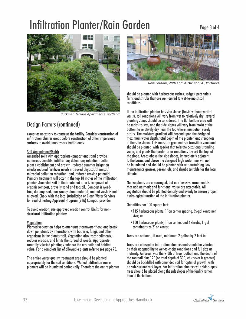
The entire water quality treatment area should be planted appropriately for the soil conditions. Walled infiltration run-on planters will be inundated periodically. Therefore the entire planter
should be planted with herbaceous rushes, sedges, perennials, ferns and shrubs that are well-suited to wet-to-moist soil conditions.
If the infiltration planter has side slopes (basin without vertical walls), soil conditions will vary from wet to relatively dry; several planting zones should be considered. The flat bottom area will be moist-to-wet, and the side slopes will vary from moist at the bottom to relatively dry near the top where inundation rarely occurs. The moisture gradient will depend upon the designed maximum water depth, total depth of the planter, and steepness of the side slopes. This moisture gradient is a transition zone and should be planted with species that tolerate occasional standing water, and plants that prefer drier conditions toward the top of the slope. Areas above the side slopes, immediately adjacent to the basin, and above the designed high water line will not be inundated and should be planted with self-sustaining, low maintenance grasses, perennials, and shrubs suitable for the local climate.
Native plants are encouraged, but non-invasive ornamentals that add aesthetic and functional value are acceptable. All vegetation should be planted densely and evenly to ensure proper hydrological function of the infiltration planter.
Quantities per 100 square feet: • 115 herbaceous plants, 1’ on center spacing, ½-gal container size; or
• 100 herbaceous plants, 1’ on center, and 4 shrubs, 1-gal container size 2’ on center.
Trees are optional; if used, minimum 2 gallon by 2 feet tall.
Trees are allowed in infiltration planters and should be selected by their adaptability to wet-to-moist conditions and full size at maturity. An area twice the width of tree rootball and the depth of the rootball plus 12” (or total depth of 30”, whichever is greater) should be backfilled with amended soil for optimal growth, with no sub-surface rock layer. For infiltration planters with side slopes, trees should be placed along the side slopes of the facility rather than at the bottom.
Buckman Terrace Apartments, Portland
Infiltration Planter/Rain Garden Page 3 of 4
New Seasons, 20th and SE Division St., Portland
Low Impact Development Approaches Handbook 33
Infiltration Planter/Rain Garden Page 4 of 4
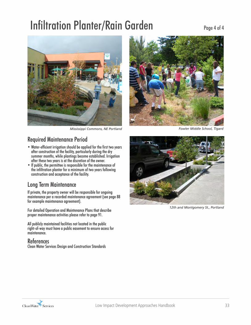
Mississippi Commons, NE Portland
12th and Montgomery St., Portland
Fowler Middle School, Tigard
Required Maintenance Period • Water-efficient irrigation should be applied for the first two years after construction of the facility, particularly during the dry summer months, while plantings become established. Irrigation after these two years is at the discretion of the owner.• If public, the permittee is responsible for the maintenance of the infiltration planter for a minimum of two years following construction and acceptance of the facility.
Long Term MaintenanceIf private, the property owner will be responsible for ongoing maintenance per a recorded maintenance agreement (see page 88 for example maintenance agreement).
For detailed Operation and Maintenance Plans that describe proper maintenance activities please refer to page 91.
All publicly maintained facilities not located in the public right-of-way must have a public easement to ensure access for maintenance.
ReferencesClean Water Services Design and Construction Standards

34 Low Impact Development Approaches Handbook
Flow-Through Planter
DescriptionFlow-through planters are structural landscaped reservoirs that collect stormwater and filter out pollutants as the water percolates through the vegetation, growing medium, and gravel. These are appropriate where soils do not drain well or there are site constraints. A liner may be required when located adjacent to buildings, over contaminated soils, and on unstable slopes. Excess stormwater collects in a perforated pipe at the bottom of the flow-through planter and drains to an approved discharge point.
Tree box filters are flow-through planters with a concrete “box” that contains filtering growing media and a tree or large shrub. Tree box filters are used singly or in multiples, often adjacent to streets where runoff is directed to them to treat stormwater runoff before it enters a catch basin.
Headwaters at Tryon Creek, Portland
buildings
parking areas & impermeable landscape
impermeablesoils
Application & LimitationsFlow-through planters may help fulfill a site’s land-scaping area requirement and can be used to manage stormwater runoff from all types of impervious surfaces on private property and within the public right-of-way. Check with the local jurisdiction if proposing to use a flow-through planter in the public right-of-way. Flow-through planters can be placed next to buildings and are ideal for sites with poorly draining soils, steep slopes or other constraints. Design variations of shape, wall treatment, and planting scheme will fit the character of any site.
Page 1 of 4
Choker Course
Hooded overflow

Low Impact Development Approaches Handbook 35
Piping for Flow Through PlantersFollow Plumbing Code requirements for piping that directs stormwater from impervious surfaces to flow-through planters. Stormwater may flow directly from the public street right-of-way
Design FactorsSizingTo calculate the planter size, multiply the impervious surface (rooftops, driveways, parking lots, etc.) area by 6%. The square footage is the peak water surface prior to overflow. For example, a 1,200 sf rooftop and 300 sf driveway (1,500 sf total impervious area) requires a 90 sf stormwater planter (1,500 x 0.06). This could be accomplished with one 9-foot by 10-foot flow-through planter.
Geometry/Slopes• Stormwater planters may be any shape, and can be designed as square, rectangular, circular, oblong, or irregular.• Regardless of the shape, a minimum planter width of 30 inches is needed to achieve sufficient time for treatment and to avoid short-circuiting. • The minimum treatment depth of 18 inches is achieved in the growing medium. • Planters are designed to evenly distribute and filter flows. Surface longitudinal slopes should be less than 0.5%.
Flow-Through Planter Page 2 of 4
Portland Rebuilding Center
or adjacent parking lot areas via curb openings. The overflow drain allows not more than 6 inches of water to pond in the planter prior to overflow. A perforated pipe system under the planter drains water that has filtered through the topsoil to prevent long-term ponding. On private property, the overflow drain and piping must meet Plumbing Code requirements and direct excess and filtered stormwater to an approved disposal point. Check with the local jurisdiction or use Clean Water Services Design and Construction Standards for additional information on piping material for use in the public right-of-way.
Structural wall(with waterproofing)
DownspoutHooded overflow
Gravel or splash block
Perforated pipe (to run length of planter)
Foundation drain Structural footing
9” Drain Rock
3” Choker Course

36 Low Impact Development Approaches Handbook
Design Factors (continued)Setbacks Check with the local building department to confirm site-specific requirements. • For planters without an impermeable liner, generally the minimum setback from building structures is 10 feet.• Typically, no building setback is required for planters lined with waterproofed concrete or 60 mil. PVC liner to prevent infiltration.
Soil Amendment/MulchAmended soils with appropriate compost and sand provide numerous benefits: infiltration; detention; retention; better plant establishment and growth; reduced summer irrigation needs; reduced fertilizer need; increased physical/chemical/microbial pollution reduction; and, reduced erosion potential. Primary treatment will occur in the top 18 inch flow-through planter. Amended soil in the treatment area is composed of organic compost, gravelly sand and topsoil. Compost is weed-free, decomposed, non-woody plant material; animal waste is not allowed. Check with the local jurisdiction or Clean Water Services for Seal of Testing Approval Program (STA) Compost provider.
To avoid erosion, use approved erosion control BMPs for flow-through planters.
VegetationPlanted vegetation helps to attenuate stormwater flows and break down pollutants by interactions with bacteria, fungi, and other organisms in the planter soil. Vegetation also traps sediments,
reduces erosion, and limits the spread of weeds. Appropriate, carefully selected plantings enhance the aesthetic and habitat value. For a complete list of allowable plants refer to page 76.The entire water quality treatment area should be planted appropriately for the soil conditions. Walled infiltration run-on planters will be inundated periodically. Therefore the entire planter should be planted with herbaceous rushes, sedges, perennials, ferns and shrubs that are well-suited to wet-to-moist soil conditions.Because the entire facility will be inundated periodically, plant the water quality treatment area with herbaceous species such as rushes, sedges, perennials, ferns and shrubs appropriate for wet-to-moist soil conditions. Most moisture-tolerant plants can withstand seasonal droughts during the dry summer months and do not need irrigation after they become established.
Native plants are encouraged, but non-invasive ornamentals that add aesthetic and functional value are acceptable. All vegetation should be planted densely and evenly to ensure proper hydrological function of the flow-through planter. Quantities per 100 square feet: • 115 herbaceous plants, 1’ on center spacing, ½-gal container size; or • 100 herbaceous plants, 1’ on center, and 4 shrubs, 1-gal container size 2’ on center.
PSU Stephen Epler Hall, Portland
RiverEast Center, SE Portland
Flow-Through Planter Page 3 of 4
Low Impact Development Approaches Handbook 37
Required Maintenance Period • Water-efficient irrigation should be applied for the first two years after construction of the facility, particularly during the dry summer months, while plantings become established. Irrigation after these two years is at the discretion of the owner.• If public, the permittee is responsible for the maintenance of the flow-through planter for a minimum of two years following construction and acceptance of the facility.
Long Term MaintenanceIf private, the property owner will be responsible for ongoing maintenance per a recorded maintenance agreement (see page 88 for example maintenance agreement).
For detailed Operation and Maintenance Plans that describe proper maintenance activities please refer to page 91.
All publicly maintained facilities not located in the public right-of-way must have a public easement to ensure access for maintenance.
Washougal Town Square
Flow-Through Planter Page 4 of 4
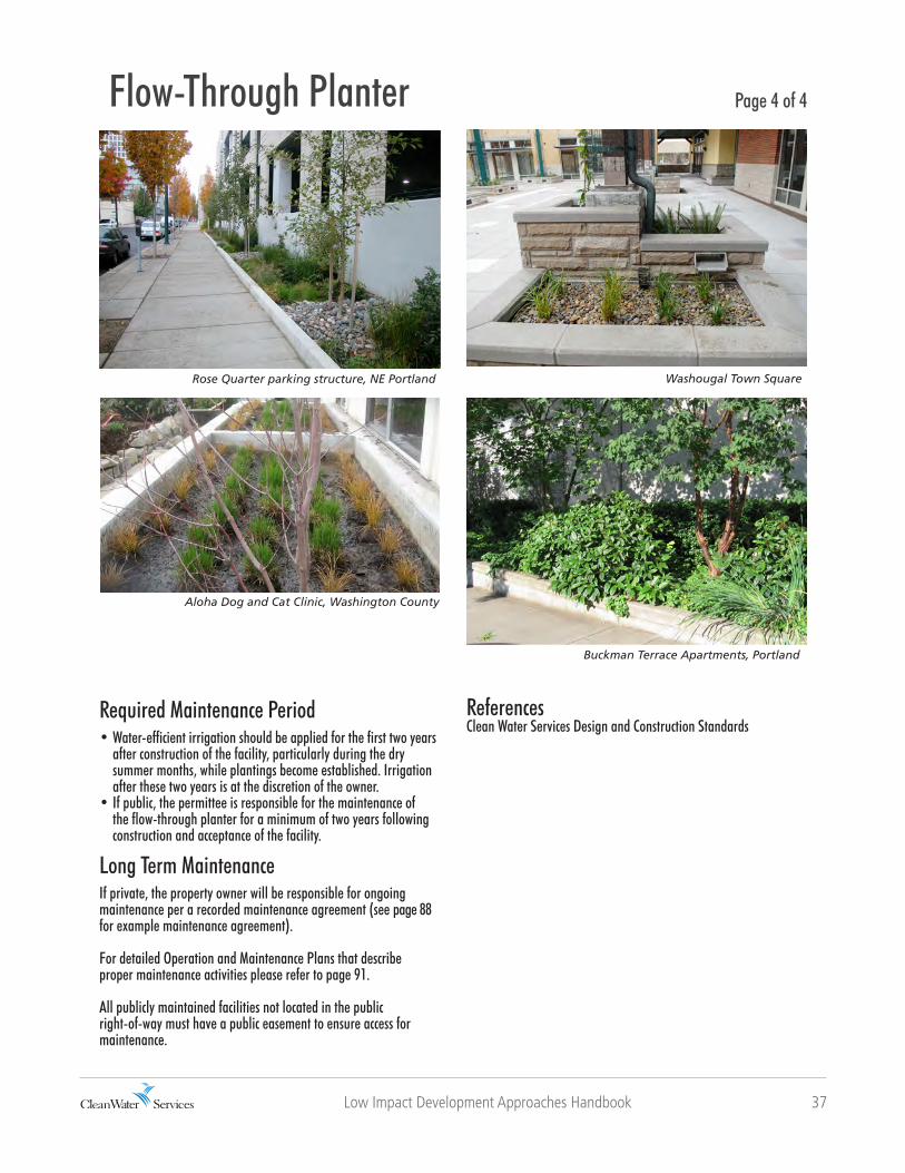
Rose Quarter parking structure, NE Portland
Aloha Dog and Cat Clinic, Washington County
Buckman Terrace Apartments, Portland
ReferencesClean Water Services Design and Construction Standards

38 Low Impact Development Approaches Handbook
LIDA Swale
DescriptionA LIDA swale is a narrow, gently sloping landscaped depression that collects and conveys stormwater runoff. The densely planted LIDA swale filters stormwater as it flows the length of the swale and allows infiltration of water into the ground. The LIDA swale discharges to a storm sewer or other approved discharge point.
Compared to vegetated swales, LIDA swales may be shorter and narrower, but require deeper levels of amended soil and a subsurface drain rock layer to compensate for the smaller size and to function effectively.
parking areas & impermeable landscape
impermeablesoils
Application & LimitationsA LIDA swale may help fulfill a site’s landscaping area requirement. LIDA swales are approved to treat stormwater flowing from all types of impervious surfaces including private property and the public right-of-way, rooftops, parking lots, and streets. Check with the local jurisdiction if proposing to use a LIDA swale in the public right-of-way.
Page 1 of 4
permeablesoils
15’ minimum swale length
Boeckman Road, Wilsonville
Top of swaleOverflow drain
Rock mulchCurb cut out
Drain rock
Check dams(for slopes >
20H:1V)

Low Impact Development Approaches Handbook 39
Design FactorsSizingThe size of the LIDA swale will depend upon the infiltration rate of existing soils. A sizing factor of 0.06 assumes the site infiltration rate is less than 2 in/hr.
For example, the size of a LIDA swale managing 1,500 square feet of total impervious area would be 90 square feet (1,500 x 0.06).
Size may be decreased if: • Demonstrated infiltration rate is greater than 2 in/hr using ASTM D3395-09 method; or • Amended soil depth is increased
Geometry/SlopesA LIDA swale’s slope end to end is at least 0.5% and no more than 6%. For sites with steeper slopes, check dams may be incorporated into the design. Side slopes from the bottom to the top of the swale must be 3:1 or less. The minimum bottom width is 2 feet, and the minimum depth is 1 foot.
LIDA Swale Page 2 of 4
Peoples Food Cooperative, SE Portland
Piping for LIDA SwalesIf needed, stormwater may be directed from impervious surfaces to LIDA swales by piping per plumbing code requirements, or may flow directly into the LIDA swale via curb openings. A LIDA swale has no underdrain. An overflow drain allows no more 6 inches of water depth to collect in the LIDA swale. On private property, the overflow drain and piping must meet plumbing code requirements
and direct excess stormwater to an approved disposal point. Check with the local jurisdiction or use Clean Water Services Design and Construction Standards for additional information on piping material for use in the public right-of-way.
Setbacks • Check with the local building department to confirm site-specific requirements.
30 ML impermeableliner
Drain rock
Non-woven geotextile
Growing medium
3H: 1V max. side slopes(4:1 without side shelf)
Subgrade
Jute matting
Choker Course 9”3”

40 Low Impact Development Approaches Handbook
Design Factors (continued)Soil Amendment/MulchAmended soils with appropriate compost and sand provide numerous benefits: infiltration; detention; retention; better plant establishment and growth; reduced summer irrigation needs; reduced fertilizer need; increased physical/chemical/microbial pollution reduction; and, reduced erosion potential. Primary treatment will occur in the top 18 inches of the LIDA swale. Amended soil in the treatment area is composed of organic compost, gravelly sand and topsoil. Compost is weed-free, decomposed, non-woody plant material; animal waste is not allowed. Check with the local jurisdiction or Clean Water Services for Seal of Testing Approval Program (STA) Compost provider.
To avoid erosion, use approved erosion control BMPs for LIDA swale.
Vegetation The entire facility area including side slopes and treatment areas are planted with vegetation appropriate for the soil conditions. Planting conditions vary from wet to relatively dry within the LIDA swale. The flat bottom will be inundated frequently and should be planted with species such as rushes, sedges, perennials, ferns, and shrubs well-suited to wet-to-moist soil conditions. The side slope moisture gradient varies from wet at the bottom to relatively dry near the top where inundation rarely occurs. The moisture gradient will vary depending upon the designed water depth, the swale depth, and side slope steepness. The transition zone from the bottom of the LIDA swale to the designed high water line or top of freeboard should be planted with sedges, rushes, perennials, ferns, and shrubs that can tolerate occasional standing water and wet-to-moist planting conditions. The areas above the designed high water line and immediately adjacent to the LIDA swale will not be regularly inundated and should be planted with self-sustaining, low maintenance grasses, perennials, and shrubs suitable for the local climate and site.
Native plants are encouraged, but appropriate, non-invasive ornamentals are acceptable for aesthetic and functional value. All vegetation should be densely and evenly planted to ensure proper hydrological function of the LIDA swale.
Quantities:Bottom of LIDA swale (wet-to-moist zone, per 100 sf)
• 115 herbaceous plants, 1’ on center spacing, ½-gal container size; or• 100 herbaceous plants, 1’ on center, and 4 shrubs, 1-gal container size, 2’ on center
Side slopes and top of LIDA swale (wet-to-moist transition zone and dry zone)• 1 tree per 300 sq. ft, minimum 2-gal container size by 2 ft-tall and• 10 shrubs (1-gal) and 70 groundcovers (½-gal) per 100 sf
Trees are allowed in LIDA swales, and may be required. Trees should be selected by adaptability to wet-to-moist conditions and size at maturity. An area twice the width of the tree rootball and the depth of the rootball plus 12” (or total depth of 30”, whichever is greater) should be backfilled with amended soil for optimal growth, with no sub-surface rock layer. Place trees along the side slopes rather than the bottom of the LIDA swale.
New Seasons, SE Division St, Portland
LIDA Swale Page 3 of 4
Ecotrust building, Portland

Low Impact Development Approaches Handbook 41
Required Maintenance Period • Water-efficient irrigation should be applied for the first two years after construction of the facility, particularly during the dry summer months, while plantings become established. Irrigation after these two years is at the discretion of the owner.• If public, the permittee is responsible for the maintenance of the LIDA swale for a minimum of two years following construction and acceptance of the facility.
Long Term MaintenanceIf private, the property owner will be responsible for ongoing maintenance per a recorded maintenance agreement (see page 88 for example maintenance agreement).
For detailed Operation and Maintenance Plans that describe proper maintenance activities please refer to page 91.
All publicly maintained facilities not located in the public right-of-way must have a public easement to ensure access for maintenance.
ReferencesClean Water Services Design and Construction Standards
LIDA Swale Page 4 of 4
Tualatin Hills Park at Portland Community College
NE Siskiyou Street, Portland
155th & Hart, Beaverton

42 Low Impact Development Approaches Handbook
Vegetated Filter Strip
DescriptionVegetated filter strips are gently sloped areas designed to receive sheet flows from adjacent impervious surfaces. Filter strips are vegetated with grasses and groundcovers that filter and reduce the velocity of stormwater. Peak stormwater flows are attenuated as stormwater travels across the filter strip and infiltrates or is stored temporarily in the soils below.
For residential driveways, center filter strips typically are 3 feet wide between two 3-foot wide paved sections. The strip treats and infiltrates stormwater only from the impervious area of the drive aisles which slope toward the center filter strip. The driveway center filter strip must be maintained to the design requirements for vegetated filter strips.
parking areas & impermeable landscape
impermeablesoils
Application & LimitationsVegetated filter strips should be integrated into the overall site design and may help fulfill a site’s landscaping area requirement. Vegetated filter strips can be used to manage stormwater runoff from a variety of impervious surfaces such as walkways and driveways on private property and within the public right-of-way. Check with the local jurisdiction if proposing to use a vegetated filter strip in the public right-of-way.
Page 1 of 3
permeablesoils
Oregon Zoo parking lot, Portland
18” Growing Medium Slope(0.5 - 6%)
(existing subgrade)
Adjacent impermeable surfaceGravel trench & level set gradeboard (if required)
Evenly distributed sheet flow of stormwater through vegetation
Check dam or berm every 10’ for slopes greater than 20H:1V
Jute matting

Low Impact Development Approaches Handbook 43
Piping for Vegetated Filter StripsNon-infiltrated flows/overflows from the vegetated filter strip are collected and conveyed to an approved system or outlet structure.Setbacks Check with local building department to confirm site-specific requirements.
Soil Amendment/MulchAmended soils with appropriate compost and sand provide numerous benefits: infiltration; detention; retention; better plant establishment and growth; reduced summer irrigation needs; reduced fertilizer need; increased physical/chemical/microbial pollution reduction; and, reduced erosion potential. Primary treatment will occur in the top 18 inches of the vegetated filter strip. Amended soil in the treatment area is composed of organic compost, gravelly sand and topsoil. Compost is weed-free, decomposed, non-woody plant material; animal waste is not allowed. Check with the local jurisdiction or Clean Water Services for Seal of Testing Approval Program (STA) Compost provider.
To avoid erosion, use approved erosion control BMPs for vegetated filter strip.
Design FactorsSizingVegetated filter strips are appropriate for all soil types and have 18” depth of growing medium. The size of the filter strip will depend upon the infiltration rate of existing soils. A sizing factor of 0.06 assumes that the site has an infiltration rate less than 2 in/hr.
For example, a facility managing 1,500 square feet of total impervious area would require a 90 sq ft filter strip (1,500 x 0.06).
Size may be decreased if:• Demonstrated infiltration rate is greater than 2 in/hr using ASTM D3395-09 method; or• Amended soil depth is increased
Geometry/SlopesThe minimum width of a vegetated filter strip is 5 feet measured in the direction of stormwater flow. The slope is between 0.5 and 6%, and the slope of the impervious area draining to the strip is less than 6%. Check dams may be required to maintain shallow slopes if the existing site slopes exceed 5%. Typically, check dams are 3 to 5 inches high and are placed every 10 feet where slopes exceed 5%.If a level spreader such as a grade board or sand/gravel trench is required to disperse runoff evenly across the filter strip, the top must be horizontal and at an appropriate height to direct sheet flow to the soil without scour. Grade boards may be any material that withstands weather and solar degradation but should not be old railroad ties, used utility poles, or other pollutant source.
Vegetated Filter Strip Page 2 of 3
Oregon Zoo parking lot

44 Low Impact Development Approaches Handbook
Design Factors (continued)
Vegetated Filter Strip Page 3 of 3
Arata Creek School, Troutdale
VegetationHerbs, shrubs and grasses can provide the vegetation needed to remove sediment and pollutants. The vegetated filter strip is planted or seeded with a mix of grasses, wildflowers, and groundcovers well-suited to moist-to-dry soil conditions. All vegetation should be self-sustaining and drought tolerant.
Native plants are encouraged, but non-invasive ornamentals that add aesthetic and functional value are acceptable. For a complete list of allowable plants refer to page 76.
Trees are not required for vegetated filter strips, but are encouraged where applicable. Tree species should be selected by their adaptability to moist-to-dry conditions and full size at maturity.The filter strip conveys evenly-distributed sheet flows of water through vegetation for treatment. Because unplanted areas may decrease stormwater treatment, the entire filter strip must have 100% vegetation coverage to ensure proper hydrologic function.
If check dams are required, plants suited to wet-to-moist planting conditions may be supplemented on the upslope side of the check dam where occasional inundation and pooling of water may occur.
Required Maintenance Period • Water-efficient irrigation should be applied for the first two years after construction of the facility, particularly during the dry summer months, while plantings become established. Irrigation after these two years is at the discretion of the owner.• If public, the permittee is responsible for the maintenance of the vegetated filter strip for a minimum of two years following construction and acceptance of the facility.
Long Term MaintenanceIf private, the property owner will be responsible for ongoing maintenance per a recorded maintenance agreement (see page 88 for example maintenance agreement).
For Detailed Operation and Maintenance Plans Refer to page 91 for maintenance .
All publicly maintained facilities not located in the public right-of-way must have a public easement to ensure access for maintenance.
ReferencesClean Water Services Design and Construction Standards

Low Impact Development Approaches Handbook 45

46 Low Impact Development Approaches Handbook
Vegetated Swale
DescriptionA vegetated swale is a gently sloping landscaped depression that collects and conveys stormwater runoff, and is narrow and at least 100 feet in length. The densely planted swale filters stormwater as it flows the length of the swale and allows infiltration of water into the ground. The vegetated swale may discharge to a storm sewer or other approved discharge point where soils do not drain well.
Vegetated swales have a required minimum length, width and stormwater residence time. See Clean Water Services Design and Construction Standards Details 700 and 710.
Westhaven Subdivision, Washington County, Oregon
parking areas & impermeable landscape
impermeablesoils
Application & LimitationsVegetated swales may help fulfill a site’s landscaping area requirement. Vegetated swales are approved to treat stormwater from all types of impervious surfaces including private property and the public right-of-way, rooftops, parking lots, and streets.
Page 1 of 4
permeablesoils
Water quality manhole(pretreatment)Inlet pipe and energy dissipatorMinimum 100 ft. treatment length
Outlet drainPipe to approved disposal point

Low Impact Development Approaches Handbook 47
Piping for Vegetated SwalesFlows coming into the vegetated swale facility are pretreated by a water quality manhole in accordance with the Design and Construction Standards. Other pretreatment may include an approved proprietary treatment device, filter strip, trapped catch basin, or other method approved by the District or City. An approved outlet structure must be provided for all flows. If location would make access for maintenance difficult, the swale may be a flow-through facility with unsumped structures.
Design FactorsSizingA vegetated swale must be at least 100 feet in length and detain stormwater for at least nine minutes for treatment as specified in Clean Water Services Design and Construction Standards.
Geometry/SlopesA vegetated swale’s slope end to end is at least 0.5% and the maximum velocity for a 25 year storm flow is 2 feet per second. Side slopes within the treatment area are 25% (4 horizontal: 1 vertical) or less; side slopes of the freeboard area above the treatment zone are 40% (2.5 horizontal: 1 vertical) or less. While the bottom of the swale is at least 2 feet wide, the treatment area is at least 6 feet wide and no more than ½ foot in depth. The freeboard area has at least one foot of vertical height. All swales have an energy dissipater such as boulders at the entrance to reduce velocities and spread the flow across the treatment area. The minimum length of the energy dissipater is 4 feet. See Clean Water Services Design and Construction Standards Detail 700.
Vegetated Swale Page 2 of 4
12” Minimum
12” Topsoil
6” MaximumFreeboard Area2.5: 1 max. slope
4:1 max. side slope
Treatment Area
24” Min. Bottom 4:1 max. side slope
Freeboard Area2.5: 1 max. slope
6’ min.
Arbor Oaks Subdivision, Washington County, Oregon
Energy dissipatorPlanting (per design guidelines)100ft. minimum swale length
2” - 3/4” river rock(2.5” - 3” deep)Jute matting
Top soil
Sub grade

48 Low Impact Development Approaches Handbook
Design Factors (continued)SetbacksCheck with the local building department to confirm site-specific requirements.
Soil Amendment/MulchThe treatment area has ¾” to 2-inch river run rock placed 2.5 to 3 inches deep on high density jute or coconut matting over 12 inches of native topsoil. The river rock, topsoil and high density jute or coconut matting extends to the top of the treatment area, topsoil and low density jute matting extends to the edge of the water quality tract or easement area.
VegetationThe entire facility including freeboard and treatment areas is vegetated according to the Standards with vegetation appropriate for the soil conditions. Planting conditions vary from wet to relatively dry within the swale. The flat bottom will be inundated frequently and should be planted with species such as rushes, sedges, perennials, and ferns, as well as shrubs that are well-suited to wet-to-moist soil conditions. The side slope moisture gradient varies from wet at the bottom to relatively dry near the top where inundation rarely occurs. The moisture gradient will vary depending upon the designed water depth, swale depth, and side slope steepness. The transition zone from the bottom of the swale to the designed high water line or top of freeboard
should be planted with sedges, rushes, perennials, and ferns, as well as shrubs that can tolerate occasional standing water, and wet-to-moist planting conditions. The areas above the designed high water line and immediately adjacent to the vegetated swale will not be regularly inundated and should be planted with self-sustaining, low maintenance grasses, perennials, and shrubs suitable for the local climate and site.
Native plants are encouraged, but non-invasive ornamentals that add aesthetic and functional value are acceptable. All vegetation should be densely and evenly planted to ensure proper hydrological function of the swale. For a complete list of allowable plants refer to page 76.
Plant SpacingA) Vegetated swales in tracts or easements less than 30 feet wide are planted as follows to achieve the specified per acre densities:i. Treatment area = 6 plugs per square foot (min. 1-inch diameter by 6-inch tall)ii. Total number of shrubs per acre = area in square feet x 0.05iii. Groundcover = plant and seed to achieve 100% coverage
B) Vegetated swales in tracts or easements 30 feet wide or more are planted as follows to achieve the specified per acre densities:i. Treatment area = 6 plugs per square foot (min. 1-inch diameter by 6-inch tall)ii. Total number of trees per acre = area in square feet x 0.01iii. Total number of shrubs per acre = area in square feet x 0.05iv. Groundcover = plant and seed to achieve 100% coverage
Tanasbourne Office Building, Washington County
Vegetated Swale Page 3 of 4
Aloha Huber Park Elementary School , Washington County

Low Impact Development Approaches Handbook 49
Required Maintenance Period • Water-efficient irrigation should be applied for the first two years after construction of the facility, particularly during the dry summer months, while plantings become established. Irrigation after these two years is at the discretion of the owner.• If public, the permittee is responsible for the maintenance of the vegetated swale for a minimum of two years following construction and acceptance of the facility.
Long Term MaintenanceIf private, the property owner will be responsible for ongoing maintenance per a recorded maintenance agreement (see page 88 for example maintenance agreement).
For detailed Operation and Maintenance Plans that describe proper maintenance activities please refer to page 91.
All publicly maintained facilities not located in the public right-of-way must have a public easement to ensure access for maintenance.
Broadview, Seattle
Vegetated Swale Page 4 of 4
Sandy Boulevard, Portland
PCC Rock Creek Campus, Beaverton
ReferencesClean Water Services Design and Construction Standards

50 Low Impact Development Approaches Handbook
Extended Dry Basin
DescriptionAn extended dry basin is a shallow landscaped depression with a flat bottom that collects and holds stormwater runoff, allowing pollutants to settle and filter out as the water infiltrates into the ground or is discharged to an approved location. An extended dry basin has two or more cells (the first cell is the forebay). An inflow pipe conveys stormwater into the basin where it is temporarily stored. Extended dry basins may infiltrate stormwater where soils have high infiltration rates, or may overflow to an approved discharge point.
parking areas & impermeable landscape
impermeablesoils
Application & LimitationsExtended dry basins may help fulfill a site’s landscaping area requirement. This type of swale is approved to treat stormwater from all types of impervious surfaces, including private property and the public right-of-way, rooftops, parking lots, and streets.
Page 1 of 4
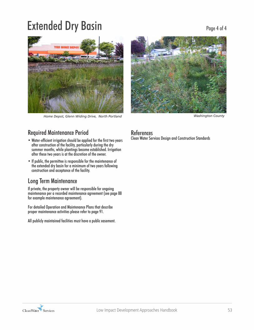
Home Depot, Glenn Widing Drive, North Portland
permeablesoils
Water quality manholeInflow pipe (from pretreatment)Forebay (min. 10% of total surface area, 20% of total treatment volume)Energy dissipatorPermanent pool depth 0.4 feet with flat bottom
Side slopes: 3H:1V
Outlet orifice
Overflow drain
Low Impact Development Approaches Handbook 51
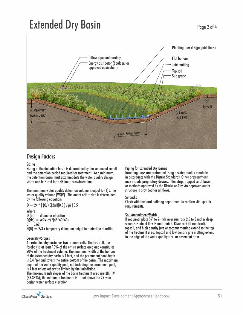
Design FactorsSizingSizing of the detention basin is determined by the volume of runoff and the detention period required for treatment. At a minimum, the detention basin must accommodate the water quality design storm and be sized for a 48 hour drawdown time.
The minimum water quality detention volume is equal to (1) x the water quality volume (WQV). The outlet orifice size is determined by the following equation: D = 24 * [ (Q/ (C[2gH]0.5 ) / pi ] 0.5Where:D (in) = diameter of orificeQ(cfs) = WQV(cf) /(48*60*60)C = 0.62H(ft) = 2/3 x temporary detention height to centerline of orifice.
Geometry/SlopesAn extended dry basin has two or more cells. The first cell, the forebay, is at least 10% of the entire surface area and constitutes 20% of the treatment volume. The minimum width of the bottom of the extended dry basin is 4 feet, and the permanent pool depth is 0.4 feet and covers the entire bottom of the basin. The maximum depth of the water quality pool, not including the permanent pool, is 4 feet unless otherwise limited by the jurisdiction.The maximum side slopes of the basin treatment area are 3H: 1V (33.33%); the minimum freeboard is 1 foot above the 25-year design water surface elevation.
Extended Dry Basin Page 2 of 4
Piping for Extended Dry BasinsIncoming flows are pretreated using a water quality manhole in accordance with the District Standards. Other pretreatment may include proprietary devices, filter strip, trapped catch basin, or methods approved by the District or City. An approved outlet structure is provided for all flows.
SetbacksCheck with the local building department to confirm site-specific requirements.
Soil Amendment/MulchIf required, place ¾” to 2-inch river run rock 2.5 to 3 inches deep where sustained flow is anticipated. River rock (if required), topsoil, and high density jute or coconut matting extend to the top of the treatment area. Topsoil and low density jute matting extend to the edge of the water quality tract or easement area.
12” Topsoil
4’ Min. Bottom Width
3:1 max. side slope
4’ MaximumBasin Depth
Inflow pipe and forebayEnergy dissipator (boulders or approved equivalant)
Planting (per design guidelines)
Flat bottomJute mattingTop soilSub grade

52 Low Impact Development Approaches Handbook
VegetationThe entire facility area (side slopes and treatment areas) is planted with vegetation appropriate for the varying planting conditions within the extended dry basin. Planting conditions vary from saturated soil to relatively dry, and several planting zones should be considered. The flat bottom of the extended dry basin to the top of the 0.4 foot permanent pool is a saturated zone and will be constantly inundated with water. The saturated zone should be planted with rushes, sedges, and other wetland species (oxygenators) that are well-suited to water-saturated, oxygen-deprived (anaerobic) planting conditions.
The side slopes above the permanent pool depth will vary from wet at the bottom to relatively dry near the top where inundation rarely occurs. This moisture gradient will vary depending upon the designed maximum water depth, basin depth, and side slope steepness. This wet-to-moist transition zone from the top of the permanent pool to the designed high water line or top of freeboard should be planted with sedges, rushes, perennials, ferns and shrubs that can tolerate occasional standing water and wet-to-moist planting conditions. The areas above the designed high water line and immediately adjacent to the extended dry basin will not be regularly inundated. The dry zone should be planted with self-sustaining, low maintenance grasses, perennials, and shrubs suitable for the local climate and site.
The use of native plants is encouraged, but appropriate, adapted non-invasive ornamentals are acceptable for added aesthetic and functional value. All vegetation should be densely and evenly planted to ensure proper hydrological function of the extended dry basin.
Plant SpacingA) Extended Dry Basins in tracts or easements less than 30 feet wide are planted as follows to achieve the specified per acre densities:i. Treatment area = 6 plugs per square foot (min. 1-inch diameter by 6-inch tall)ii. Total number of shrubs per acre = area in square feet x 0.05iii. Groundcover = plant and seed to achieve 100% coverage
B) Extended Dry Basins in tracts or easements 30 feet wide or more are planted as followings to achieve the specified per acre densities:i. Treatment area = 6 plugs per square foot (min. 1-inch diameter by 6-inch tall)ii. Total number of trees per acre = area in square feet x 0.01iii. Total number of shrubs per acre = area in square feet x 0.05iv. Groundcover = plant and seed to achieve 100% coverage
Extended Dry Basin Page 3 of 4
Washington County
Low Impact Development Approaches Handbook 53
Required Maintenance Period • Water-efficient irrigation should be applied for the first two years after construction of the facility, particularly during the dry summer months, while plantings become established. Irrigation after these two years is at the discretion of the owner.
• If public, the permittee is responsible for the maintenance of the extended dry basin for a minimum of two years following construction and acceptance of the facility.
Long Term MaintenanceIf private, the property owner will be responsible for ongoing maintenance per a recorded maintenance agreement (see page 88 for example maintenance agreement).
For detailed Operation and Maintenance Plans that describe proper maintenance activities please refer to page 91.
All publicly maintained facilities must have a public easement.
Home Depot, Glenn Widing Drive, North Portland Washington County
Page 4 of 4
ReferencesClean Water Services Design and Construction Standards
Extended Dry Basin
54 Low Impact Development Approaches Handbook
Constructed Water Quality Wetland
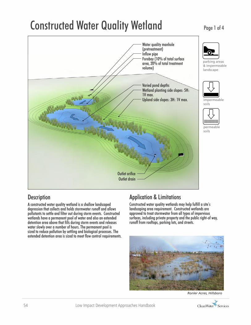
DescriptionA constructed water quality wetland is a shallow landscaped depression that collects and holds stormwater runoff and allows pollutants to settle and filter out during storm events. Constructed wetlands have a permanent pool of water and also an extended detention area above that fills during storm events and releases water slowly over a number of hours. The permanent pool is sized to reduce pollution by settling and biological processes. The extended detention area is sized to meet flow control requirements.
parking areas & impermeable landscape
impermeablesoils
Application & LimitationsConstructed water quality wetlands may help fulfill a site’s landscaping area requirement. Constructed wetlands are approved to treat stormwater from all types of impervious surfaces, including private property and the public right-of way, runoff from rooftops, parking lots, and streets.
Page 1 of 4
permeablesoils
Ronler Acres, Hillsboro
Water quality manhole (pretreatment)Inflow pipeForebay (10% of total surface area, 20% of total treatment volume)
Varied pond depthsWetland planting side slopes: 5H: 1V max.Upland side slopes: 3H: 1V max.
Outlet orificeOutlet drain

Low Impact Development Approaches Handbook 55
Design FactorsSizingSizing of the constructed water quality wetland is determined by the volume of runoff and the required detention time for treatment. At a minimum, the detention basin must accommodate the water quality design storm and be sized for a 48 hour drawdown time. The minimum water quality detention volume is equal to (1)x the water quality volume (WQV). The outlet orifice size is determined by the following equation: D = 24 * [ (Q/ (C[2gH]0.5 ) / Pi ] 0.5Where: D (in) = diameter of orifice Q(cfs) = WQV(cf) /(48*60*60) C = 0.62 H(ft) = 2/3 x temporary detention height to centerline of orifice.
Geometry/SlopesConstructed water quality wetlands have two or more cells. The first cell, known as the forebay, is at least 10% of the entire surface area and constitutes 20% of the treatment volume. If space is limited, one cell with a forebay at the inlet will settle sediments and distribute flow across the wet pond.
Unlike the flat bottom of an extended dry basin, in a constructed wetland the pool depth varies throughout the pond. Not including the permanent pool, the maximum depth of the water quality pool is 2.5-feet unless otherwise approved by the jurisdiction.
Constructed Water Quality Wetland Page 2 of 4
Side slopes for wetland planting areas should not exceed 5H: 1V (20%) and side slopes for non-wetland planting areas should not exceed 3H: 1V (33.33%). The minimum freeboard height is 1 foot from the 25-year design water surface elevation. A perimeter 10 to 20 feet wide provides inundation during storm events.
Piping for Constructed Water Quality WetlandsIncoming flows to the water quality wetland facility are pretreated by a water quality manhole or other approved pretreatment method in accordance with District Standards. Other pretreatment methods may include proprietary devices, filter strip, trapped catch basin, or other methods as approved by the District or City. An approved outlet structure is provided for all flows.
SetbacksCheck with the local building department to confirm site-specific requirements.
Varied pond depthsForebay (10% of total surface area, 20% of total treatment volume)

56 Low Impact Development Approaches Handbook
Design Factors (continued)Soil Amendment/MulchA minimum of 12” of topsoil should be applied to all treatment areas.
VegetationThe entire facility area (permanent pool, side slopes and perimeter zone) are planted with vegetation appropriate for the varying planting conditions within the constructed wetland. Planting conditions within the wetland vary from saturated soil to relatively dry, and several planting zones should be considered. The zone between the bottom of the constructed wetland and the top of the permanent pool will be constantly inundated with water and have saturated soils. This wet zone should be planted with rushes, sedges, and other wetland species that are well-suited to water-saturated, oxygen-deprived (anaerobic) planting conditions. The variable depth of the bottom of the wetland will create a series of micro planting conditions. Within this wet zone, areas of open water may be too deep to support significant vegetation. The side slopes above the permanent pool depth to the outer edges of the perimeter zone will have a moisture gradient that varies from wet near the bottom to relatively dry near the edge of the
perimeter area where inundation rarely occurs. This moisture gradient will vary depending upon the maximum designed water depth, constructed wetland depth, and side slope steepness. This moist-to-wet transition zone from the top of the permanent pool to the designed high water line or top of freeboard should be planted with sedges, rushes, perennials, ferns and shrubs that can tolerate occasional standing water and wet-to-moist planting conditions. Areas above the designed high water line and immediately adjacent to the water quality wetland is a dry zone and will not be regularly inundated. The dry zone should be planted with self-sustaining, low maintenance grasses, perennials, and shrubs suitable for the local climate.
The planting design should minimize solar exposure of open water areas to reduce heat gain in the water. Lower water temperatures help to maintain healthy oxygen levels and minimize algae blooms. Trees or other appropriate vegetation should be planted at the perimeter of the pond to maximize shading.
The use of native plants is encouraged, but adapted, non-invasive ornamentals are acceptable for added aesthetic and functional value.
Constructed Water Quality Wetland Page 3 of 4
Oleson Woods Apartments, Tigard

Low Impact Development Approaches Handbook 57
Vegetation (continued)All vegetation should be densely and evenly planted to ensure proper hydrological function of the water quality wetland.
Plant SpacingConstructed Water Quality Wetlands in tracts or easements are to be planted as follows to achieve the specified per acre densities:i. Treatment area = 6 plugs per square foot (min. 1-inch diameter by 6-inch tall)ii. Total number of trees per acre = area in square feet x 0.01iii. Total number of shrubs per acre = area in square feet x 0.05iv. Groundcover = plant and seed to achieve 100% areal coverage
Required Maintenance Period • Water-efficient irrigation should be applied for the first two years after construction of the facility, particularly during the dry summer months, while plantings become established. Irrigation after these two years is at the discretion of the owner.• If public, the permittee is responsible for the maintenance of the constructed water quality wetland for a minimum of two years following construction and acceptance of the facility.
Long Term MaintenanceIf private, the property owner will be responsible for ongoing maintenance per a recorded maintenance agreement (see page 88 for example maintenance agreement).
For detailed Operation and Maintenance Plans that describe proper maintenance activities please refer to page 91.
All publicly maintained facilities must have a public easement.
ReferencesClean Water Services Design and Construction Standards
Synopsys, Hillsboro
Constructed Water Quality Wetland Page 4 of 4
Ronler Acres, Hillsboro

58 Low Impact Development Approaches Handbook
Conveyance and Stormwater Art
DescriptionStormwater conveyance is the flow, movement or transfer of stormwater from one location to another. Stormwater conveyance techniques deliberately transport water from where it falls to where it will be treated. All Low Impact Development Approaches (LIDA) convey stormwater, and the movement and slowing of water through these facilities improves water quality and attenuates peak stormwater flows. There are design standards for each type of LIDA, but there is flexibility to allow creativity and site-specific adaptation for how stormwater enters and passes through these facilities to meet required performance criteria.
buildings
parking areas & impermeable landscape
impermeablesoils
Page 1 of 4
Overflow
SecondaryInfiltration
to Planting Bed
Outfall
Downspout FromRooftop
Basin
Reclaimed Concrete
Slabs
PrimaryInfiltration
Rain Garden
RiverEast Center, Portland. Stormwater from the rooftop is conveyed by a downspout into a sculptural basin made with reclaimed concrete from the retrofit of the building. The basin detains and slows runoff before it flows into a series of adjacent rain gardens, grated runnels and swales.
permeablesoils
Application & LimitationsThere are two general methods of stormwater conveyance, underground and above ground.
1. Underground conveyance channels stormwater in pipes below-ground and typically requires a plumbing permit. (See Design and Construc- tion Standards for additional details and requirements.)
2. Above ground conveyance moves water on the surface of the ground. In applicable locations, such as LIDA facilities, the benefits of above ground conveyance may include: • Lower construction costs due to less excavation and underground piping• Less site disturbance • Improved oxygenation and cleansing of water• More opportunities for artistic and creative design• Enhanced public awareness of urban stormwater

Low Impact Development Approaches Handbook 59
Conveyance and Stormwater Art Page 2 of 4
Estacada Library. Stormwater is conveyed from the rooftop to an infiltration basin. As the basin fills with water, it overflows into a connected series of swales and additional infiltration basins that convey stormwater around the library.
North Main Village, Milwaukie. Stormwater is the featured design element for this residential courtyard. Water from rooftops is conveyed by steel scuppers into decorative planters to meandering runnels and water quality swales.
New Seasons, 20th and Division, Portland. A whimsical steel sculpture conveys stormwater from a grocery store rooftop into an infiltration planter.
Headwaters at Tryon Creek, SW Portland. Headwaters is a residential development where senior housing, town homes, and an apartment building were designed to be integrated with the daylighting (removal from an underground piping system) of a tributary of Tryon Creek.

60 Low Impact Development Approaches Handbook
Conveyance and Stormwater Art Page 3 of 4
PSU Stephen Epler Hall. Stormwater from the impermeable plaza area is directed to bands of granite stone that are strategically placed at low drainage points to convey stormwater to a series of flow-through planters.
Block 11, Washougal, WA. Stormwater from surrounding rooftops is directed into the plaza’s vertical sculpture before entering flow-through planters.
Team Estrogen Warehouse, Washington County. Stormwater from the warehouse roof is conveyed by a scupper into a concrete splash basin. The velocity of the water is slowed before the water flows into a vegetated swale.
“Downspout 101”, Seattle (artist Buster Simpson). The branching downspout is part of a public art project called “Growing Vine Street” that uses visual and provocative conveyance techniques to raise awareness of the stormwater flowing through the neighborhood.

Low Impact Development Approaches Handbook 61
Conveyance and Stormwater Art Page 4 of 4
New Seasons, Beaverton. This example was brought up in our first meeting to be included in this fact sheet.
Headwaters at Tryon Creek, SW Portland. The rounded and stepped design of these infiltration planters are molded to the specific conditions of the site. The concrete walls are a creative interpretation of check dams that are used to convey water across flat surfaces over steep topography.
Local 49, Portland. Stormwater is conveyed from the rooftop by a decorative stainless steel metal scupper into the courtyard. Water flows from the scupper into a concrete runnel, detention basin and planters.
Glencoe Elementary School Rain Garden, Portland. Stormwater from neighboring streets is conveyed into an infitration rain garden filled with native plants and rock berms that slow the flow of water. The rain garden is also a visual amenity and educational component for the elementary school (photo courtesy of 2008 Portland Stormwater Manual).
10th @ Hoyt, Portland. The design of this urban courtyard is inspired by Persian gardens. Downspouts convey stormwater from the surrounding rooftops into a series of channels and colorful fountains.
New Seasons, Beaverton. Two decorative scuppers collect and convey roof stormwater into an infiltration basin.

62 Low Impact Development Approaches Handbook
Planting Design and Habitat
DescriptionA habitat is a space that provides food, water and shelter for the survival and reproduction of an organism. Low Impact Development Approaches (LIDA) facilities mimic the natural habitats, processes and hydrology of a particular site. The environmental benefits of LIDA facilities include:
• Less disturbance to sites than conventional stormwater management methods • Reduced and delayed peak stormwater flows• Reduced discharge of pollutants• Increased planted space and habitat • Creation of a multifunctional landscape that enhances visual and functional amenities
All of these on-site benefits generate a variety of off-site benefits that preserve and enhance riparian and wetland habitats “downstream” from the facility by reducing the negative environmental affects associated with urban development.
Application & LimitationsNearly all LIDA facilities have the potential to create and improve habitat on and near the site. Water is one of the most important factors in the creation of habitat, and because most LIDA facilities receive large amounts of stormwater they offer a great opportunity to create habitat. Planting vegetation is one of the most practical ways to create habitat within a LIDA facility.
Each LIDA facility has planting design guidelines such as required plant spacing and plant types, but there is flexibility to maximize habitat for a variety of organisms such as invertebrates, amphibians, small mammals and birds.
Page 1 of 4
Tanner Springs Park, Portland. Stormwater from surrounding impermeable surfaces is conveyed and recirculated through a constructed wetland and filter strip to be cleansed and aerated. The filter strip and wetland edge is planted with a variety of native plants based on their suitability to the different planting conditions.
buildings
parking areas & impermeable landscape
impermeablesoils
permeablesoils

Low Impact Development Approaches Handbook 63
Design FactorsRelationship of Form and HydrologyCareful consideration of the planting conditions within a LIDA facility will help to ensure the success of a planting design.
Planting conditions for sloped, basin-like stormwater facilities such as swales, extended dry basins, constructed water quality wetlands, and infiltration basins have a variety of moisture levels. Soil conditions at and near the bottom of the facility are wet due to frequent or constant inundation, and side slopes vary from wet at the bottom to relatively dry near the top. The moisture gradient varies with the designed maximum water depth, the time it takes for a facility to drain after a storm event, and the steepness of the side slopes. The zone from the bottom of the facility to the designed high water line or top of freeboard should be planted with plants that tolerate occasional standing water and wet-to-moist conditions. Above the designed high water line vegetation is not affected by stormwater entering the facility and should be planted with species well-suited to the local climate and context.
Planting conditions are more uniform for flow-through and infiltration planters because of the relatively flat surface.
Planting Design and Habitat Page 2 of 4
Planting conditions for LIDA facilities without sloped edges (such as concrete flow-through planters and infiltration planters) are largely uniform.
Saturated Soils (these will be continuously saturated areas for constructed wetlands and
extended dry basins)
Wet-to-Moist Soils (Frequent to occasional inundation
transitional zone)
Drier Soils(above designed highwater line)
Uniformly Wet-to-Moist Soils(with seasonal drought)
Planting conditions and habitats are varied for LIDA facilities with side slopes, such as vegetated swales, LIDA swales, extended dry basins and water quality wetlands.
Beaumont Village, Portland
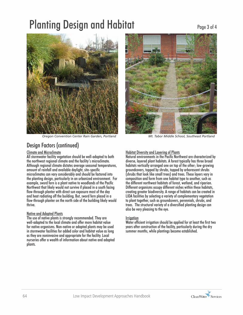
64 Low Impact Development Approaches Handbook
Design Factors (continued)Climate and MicroclimateAll stormwater facility vegetation should be well-adapted to both the northwest regional climate and the facility’s microclimate. Although regional climate dictates average seasonal temperatures, amount of rainfall and available daylight, site-specific microclimates can vary considerably and should be factored into the planting design, particularly in an urbanized environment. For example, sword fern is a plant native to woodlands of the Pacific Northwest that likely would not survive if placed in a south facing flow-through planter with direct sun exposure most of the day and heat radiating off the building. But, sword fern placed in a flow-through planter on the north side of the building likely would thrive.
Native and Adapted PlantsThe use of native plants is strongly recommended. They are well-adapted to the local climate and offer more habitat value for native organisms. Non-native or adapted plants may be used in stormwater facilities for added color and habitat value as long as they are noninvasive and appropriate for the facility. Local nurseries offer a wealth of information about native and adapted plants.
Oregon Convention Center Rain Garden, Portland
Planting Design and Habitat Page 3 of 4
Mt. Tabor Middle School, Southeast Portland
Habitat Diversity and Layering of PlantsNatural environments in the Pacific Northwest are characterized by diverse, layered plant habitats. A forest typically has three broad habitats vertically arranged one on top of the other; low-growing groundcovers, topped by shrubs, topped by arborescent shrubs (shrubs that look like small trees) and trees. These layers vary in composition and form from one habitat type to another, such as the different northwest habitats of forest, wetland, and riparian. Different organisms occupy different niches within these habitats, creating greater biodiversity. A range of habitats can be created in LIDA facilities by selecting a variety of complementary vegetation to plant together, such as groundcovers, perennials, shrubs, and trees. The structural variety of a diversified planting design can also be very pleasing to the eye.
IrrigationWater efficient irrigation should be applied for at least the first two years after construction of the facility, particularly during the dry summer months, while plantings become established.
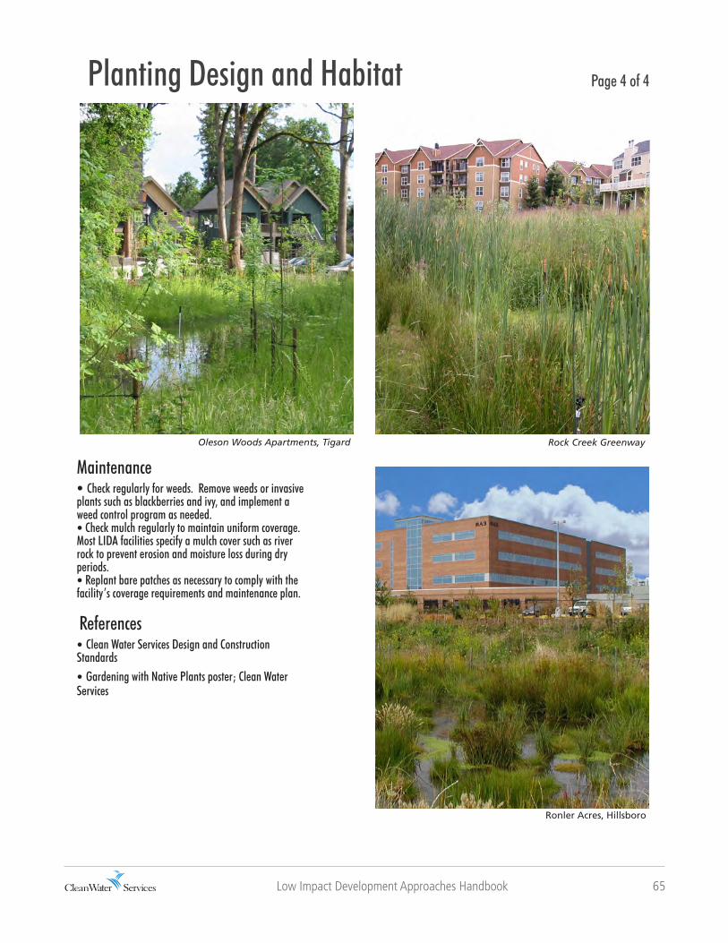
Low Impact Development Approaches Handbook 65
Maintenance• Check regularly for weeds. Remove weeds or invasive plants such as blackberries and ivy, and implement a weed control program as needed. • Check mulch regularly to maintain uniform coverage. Most LIDA facilities specify a mulch cover such as river rock to prevent erosion and moisture loss during dry periods. • Replant bare patches as necessary to comply with the facility’s coverage requirements and maintenance plan.
References• Clean Water Services Design and Construction Standards• Gardening with Native Plants poster; Clean Water Services
Planting Design and Habitat Page 4 of 4
Rock Creek GreenwayOleson Woods Apartments, Tigard
Ronler Acres, Hillsboro