chapter 4 dvd system design - university of...
TRANSCRIPT

stem
ans of
istic
e vapor
d early
on tool
and
esign
cuum
rucible
l to this
might
gular,
ology
-offs in
the
Chapter 4
DVD System Design
In its most basic form (Fig. 3.1), the proposed Directed Vapor Deposition (DVD) sy
will consist of four primary components: a source of material to be evaporated, a me
creating an atomistic vapor from the source, a flow of carrier gas in which the atom
vapor is transported through the processing chamber, and a substrate upon which th
deposits. As discussed in Chapters 1, 2, and 3, an electron beam gun was identifie
in the technology development process as the desired source material evaporati
because of its ability to vaporize refractory (i.e. high melting point) materials rapidly
cleanly. To create a basic but effective demonstration of the DVD concept, the d
work described in this chapter seeks to integrate e-beam technology into a low va
processing environment where the vapor stream generated by the e-beam from a c
can be captured in a carrier gas stream for transport to a chosen substrate. Centra
design approach is the thought that placing e-beam evaporant in a carrier gas stream
improve the vapor stream’s characteristics for specific applications (e.g., spatial, an
and energy distribution as described in the Background chapter), making the techn
an important vapor phase material synthesis tool. This chapter describes the trade
specifications of the many DVD system components which will fit together to form
56

Chapter 4. DVD System Design 57
naly-
an be
tems in
cuum,
rier to
ssing
cessing
for the
cation
volt-
aracter-
um)
ng the
d gener-
pora-
ibed in
-vac-
DVD material synthesis tool. As the work of this chapter will demonstrate, detailed a
sis of the basic idea laid out in Chapter 3 is required before the DVD concept c
reduced to practice in a functioning material processing system.
4.1 Electron Beam Gun
Although most electron beam gun technology has been developed to operate in sys
which both the gun and processing chamber are maintained at medium or high va
the Background chapter (section 2.1.3.) noted that there exists no scientific bar
employing an e-beam gun in a system which maintains a low vacuum in its proce
chamber, as desired for the DVD system. To create such a system capable of pro
refractory materials at high rates, numerous analyses must be made before a gun
DVD system can be specified. The primary design issues for the gun include specifi
of the maximum power generation capability and the required e-beam accelerating
age, selection of the beam generation mechanism, and choice of desired e-beam ch
istics (e.g. beam diameter and scanning radius/rate).
4.1.1. Maximum e-beam gun power requirements
Specification of the maximum e-beam gun power capability for new (high or low vacu
evaporation systems is challenging because of the uncertainty involved in determini
magnitude of the various e-beam energy losses between generation of the beam an
ation of the vapor. The amount of e-beam energy actually available for material eva
tion in a DVD system depends upon the energy losses which include those descr
various references [11, 37] as well as additional energy sinks resulting from the low
uum DVD operating environment:

Chapter 4. DVD System Design 58
f the
e.
beam
an lead
mate-
or the
would
power
ntional
acuum
was
an e-
ation
oint. In
elow
ment
the
n the
• Inside the gun due to some fraction of the beam impinging on various portions o
gun,
• In the gas and vapor cloud due to electron scattering collisions,
• From the evaporant material surface as a result of electron backscattering,
• Through conduction into the crucible containing the melt material,
• From the radiating molten evaporant surface, and
• Through convection caused by the gas jet blowing across the evaporant surfac
Schiller [11] and Storer [21] have indicated that, in a conventional high vacuum e-
system employing a water-cooled crucible, the standard energy sinks listed above c
to as little as 10% of the initial beam power actually being transformed into source
rial evaporation energy. Calculation of a necessary e-beam gun power capability f
DVD system assumed that even less of the initial beam power, as little as 3 - 3.5%,
actually contribute to material evaporation. This small number was selected for gun
calculations since energy losses in the DVD system should exceed those in a conve
e-beam system due to increased beam dissipation inside the gun and in the low v
environment and due to gas jet convection.
One of the materials of primary interest for fiber coating in the e-beam DVD system
titanium. An e-beam power calculation was undertaken to determine how powerful
beam gun would be required to deposit titanium in the DVD system. This calcul
assumed that the temperature of the melt had to be raised to the material’s boiling p
fact, studies have shown [11] that controlled e-beam evaporation typically occurs b
the material’s boiling point at a source vaporization temperature (Tv) which induces an
equilibrium vapor pressure of about 1 Pa. During calculation of the power require
results of Table 4.1, determination of ∆H up to a vapor pressure of 1 Pa rather than
boiling point generally decreased the power required by about 10%. However, give

Chapter 4. DVD System Design 59
an the
can be
5].
.2
1
30
73
.0
6
.3
5
1
uncertainties in power losses throughout the system, using the boiling point rather th
1 Pa vapor pressure point was considered an acceptable safety factor.
The e-beam gun power required to evaporate some material at a specified rate
determined using the data of Table 4.1 and the following equation [11]:
(4.1)
where W = Power required (W),
re = Evaporation rate (m3/min),
Table 4.1: Thermophysical dataCalculation of power required to evaporate materials in the DVD system [194, 19
Elements
Al Cu Mo Ni Nb Si Ti V Y Zr
At. Wt. (g/mol) 27.0 63.6 95.9 58.7 92.9 28.1 47.9 50.9 88.9 91
Density (g/cm3) 2.70 8.96 10.2 8.90 8.57 2.33 4.54 6.11 4.47 6.5
Tm (K) 933 1356 2893 1726 2740 1683 1940 2188 1803 21
Tb (K) 2793 2840 4880 3180 5010 2628 3560 3680 3573 46
c p (
J/K
mol
) =
a +
bT
+ c
T-2
solid
a 20.7 22.6 24.1 17.0 23.7 23.9 22.1 20.5 23.9 22
b x 103 12.3 5.6 1.2 29.5 4.0 2.5 10.0 10.8 7.55 11.
c x 10-5 - - - - - -4.1 - 0.8 0.3 -3.8
liqu
id
a 29.3 - - 29.7 - - 32.6 36.0 43.1 31.4
b x 103 - - - 4.18 - - - - - -
c x 10-5 - - - -9.3 - - - - - -
Lf (kJ/mol) 10.4 13.0 35.5 17.2 29.3 50.7 17.5 16.7 11.4 19
Le (kJ/mol) 290 306 590 375 681 386 427 456 371 57
∆H (KJ/mol) 372 350 744 498 659 475 550 575 508 66
Power (kW) 6.4 8.5 14 13 10 6.8 9.0 12 4.4 8.1cp = Specific heat at constant pressure
Lf = Latent heat of fusion
Le = Latent heat of evaporation
Wre H∆Vε
------------=

Chapter 4. DVD System Design 60
ora-
ere
The
) at
initial
. As a
uired
1.
pecifi-
) and
n is
aterial
t to
evapo-
n effi-
rating
tar-
mate-
= Enthalpy required to raise material from room temperature to evap
tion temperature (kJ/mol),
V = Molar density of material (m3/mol), and
ε = Efficiency of energy utilization (3 - 3.5%).
For titanium deposition using DVD, the following material deposition parameters w
specified based upon general industry specifications for the MMC application [20].
gun should be capable of depositing material at a rate of 10 - 15 µm/min [21] onto 10
meters of 140 µm diameter, rotating fiber (e.g. SCS-6 SiC fibers rotating at 10 rpm
20% deposition efficiency. (All of these numbers factor into a determination of re, the
evaporation rate required in the system.) Calculation shows that about 9 kW of
beam power would be required to evaporate titanium for the desired rate of coating
result of this calculation, a 10 kW gun was specified. For comparison, the power req
to coat an identical substrate with other materials is shown at the bottom of Table 4.
4.1.2. Accelerating voltage selection
Although the calculations of the previous section produce a reasonable gun power s
cation, that specification is based on several assumptions: deposition efficiency (20%
energy utilization efficiency (3 - 3.5%). Refining the deposition efficiency specificatio
difficult because a DVD system does not yet exist to coat fibers and determine the m
utilization capabilities of the system. The energy utilization efficiency is also difficul
quantify without an actual system to analyze. However, to ensure that the gun can
rate material at a rate greater than or equal to that which is desired, energy utilizatio
ciency can be maximized through the choice of an appropriate e-beam accele
voltage which will minimize e-beam energy dissipation during travel from cathode to
get. As noted in section 2.1.3., the actual beam power transmitted to the evaporation
H∆
Chapter 4. DVD System Design 61
tom /
ground
attering
gh the
erials
mbina-
nergy
ource
which
raction
e over
gth of
locity
ltages
experi-
eason-
ge is
he gas
rial will be less than 10 kW due in part to beam energy dissipation as a result of a
electron scattering interactions in the gun and chamber. The discussion in the Back
section noted that increasing the accelerating voltage and thereby decreasing the sc
cross-section of the atoms in the chamber would increase beam propagation throu
low vacuum. To ensure an ability to evaporate rapidly even high melting point mat
(e.g. graphite, tungsten, and molybdenum), an accelerating voltage / carrier gas co
tion should be chosen which will transmit as much as possible of the beam’s initial e
to the source material.
The amount of electron beam scattering which occurs between the initial electron s
and the final target depends upon the number of gas atom / electron interactions
occur (i.e. the gas pressure in the chamber), the range of the gas atom / electron inte
potential (Range increases with gas atom atomic number.), and the length of tim
which the electron is acted upon by the interaction potential. This final element, len
time, is directly proportional to the velocity of the electrons in the beam where the ve
is determined by the accelerating voltage utilized in the gun (Higher accelerating vo
correspond to higher velocities.). Arata [49] has proposed equations, based upon
mental study, which describe electron-beam penetration through an inert gas with r
able accuracy using a modified Bethe stopping power formula. (The Bethe ran
considered to be the total distance that the beam’s electrons can travel through t
before losing all of their energy [48].) The expression proposed by Arata [49] was:
(4.2)
where B = Beam voltage at distance h (m) from nozzle exit (kV),
Bo = Initial beam voltage (kV), and
B Bo 1hRe
-----– 1 2⁄
=
Chapter 4. DVD System Design 62
ctron,
uation
e a cer-
that
Born
the
e elec-
ating
tomic
d for
Re = Electron range (m).
Re is a complicated function of the initial electron energy, the classic radius of an ele
and the temperature, density and atomic number of the gas in the chamber [49]. Eq
(4.2) assumes that the gas density is constant along the e-beam path and that “abov
tain fractional energy transfer, ε1, the atomic electrons can be regarded as free, so
Moller’s cross section for scattering of free electrons by free electrons at rest in [sic.]
approximation is applicable [196].” Moller’s cross-section is simply a description of
range of the interaction potential between the free electrons in the e-beam and fre
trons at rest (i.e. around a gas atom nucleus).
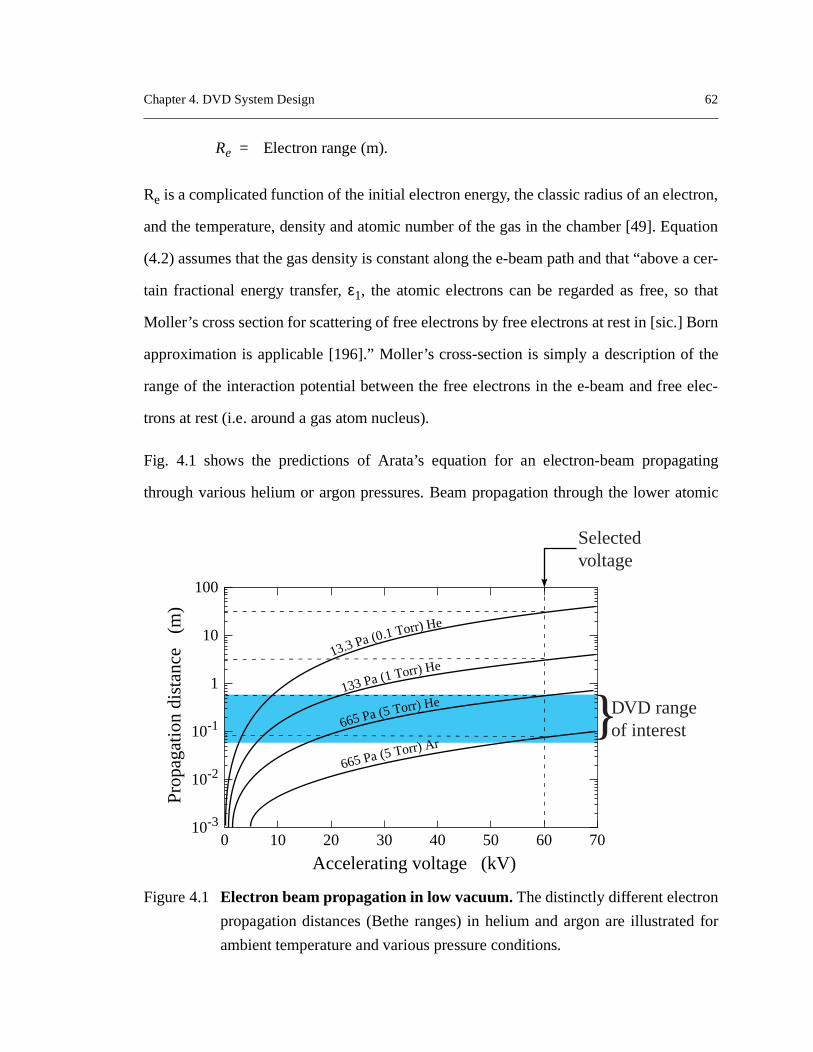
Fig. 4.1 shows the predictions of Arata’s equation for an electron-beam propag
through various helium or argon pressures. Beam propagation through the lower a
Figure 4.1 Electron beam propagation in low vacuum. The distinctly different electron
propagation distances (Bethe ranges) in helium and argon are illustrate
ambient temperature and various pressure conditions.
10-3
10-2
10-1
1
10
Accelerating voltage (kV)
Pro
paga
tion
dist
ance
(m
) 100
0 10 20 30 40 50 60 70
13.3 Pa (0.1 Torr) He
133 Pa (1 Torr) He
665 Pa (5 Torr) He
665 Pa (5 Torr) Ar}DVD range
of interest
Selectedvoltage

Chapter 4. DVD System Design 63
poten-
, Fig.
rhaps
advan-
gas in
accel-
ini-
wire,
out of
number helium is superior because of the shorter range electron / atom interaction
tial in that system. While the propagation of electrons through helium is clearly better
4.1 indicates that the use of low partial pressures of other inert (e.g., argon) or pe
even reactive carrier gases (e.g. oxygen) is feasible should it offer some processing
tage. Given the results of Fig. 4.1, helium was chosen as the primary inert carrier
the DVD system, and the e-beam accelerating voltage was specified as 60 kV. This
erating voltage level was selected to afford fairly efficient beam propagation while m
mizing cost and x-ray problems associated with higher accelerating voltages [11].
4.1.3. Selection of an e-beam generation source
As Schiller et al. [11] explain in their book Electron Beam Technology, various types of
electron generating cathodes are available for use in e-beam systems, including
strip-type, and solid cathodes. Filaments for e-beam systems are generally made
tungsten, a tungsten-rhenium alloy, or lanthanum hexaboride (LaB6). LaB6 filaments gen-
erally require vacuums of at least 5x10⁻⁶ Torr (~5x10⁻⁴ Pa) or better to minimize reaction
with the oxygen in air. This requirement makes LaB6 an unlikely material for use in the
DVD system where pressures in the beam generating space could reach 8x10⁻⁵ Torr. In
addition, LaB6 filaments usually generate just 10 - 100 µA of beam current [11]. Given
that:
(4.3)
where I = Beam current (A) and
B = Beam accelerating voltage (kV),
a LaB6 system with a 60 kV accelerating voltage and 100 µA of beam current would gen-
erate at most 6 W of power rather than the required 9 kW! Thus, LaB6 filaments, which
W IB=
Chapter 4. DVD System Design 64
, were
of the
cath-
rate a
sur-
dustrial
current
onsul-
tung-
p was
the ini-
them
pass-
rd the
de has
n with
lectron
hieved
ertain
free
athode
e and
f oper-
are often considered superior electron emission sources in electron microscopes
deemed unacceptable in the DVD system due to the emission current requirements
DVD system and due to the vacuum requirements of a LaB6 filament [11, 48].
For filaments made out of tungsten or a tungsten-rhenium alloy, strip-type and solid
odes were easily eliminated from consideration. Strip-type filaments do not gene
beam of electrons, as desired for the DVD application, but rather a planar-emitting
face. Solid cathodes are generally used in much larger e-beam systems at the in
rather than research scale (i.e., systems generating 1.2 MW of power with a beam
of 5 - 40 A, far more energy than is required for the system under design here). In c
tation with e-beam gun manufacturers [197], a small-area cathode in the form of a
sten bolt cathode surrounded by a tungsten wire cathode inside of a Wehnelt cu
selected to generate the beam electrons (Fig. 4.2). The Wehnelt cup serves to shape
tial beam generated from the bolt cathode by repelling the electrons and forcing
down through the small hole in the electric field of the cup.
During operation, the tungsten wire cathode of this system is heated electrically by
ing a current until it emits electrons via thermionic emission. These electrons bomba
bolt cathode, heating it and leading to its own electron emission. Once the bolt catho
begun to emit electrons, electron bombardment from the wire cathode in combinatio
direct electric current heating increases the bolt cathode temperature, increases its e
current emission density, and results in a larger emitting surface than would be ac
through bolt operation only [11]. During electron emission from the hot cathodes, a c
fraction of the tungsten is vaporized. A portion of this tungsten is then ionized by the
electrons in the system. This ionized tungsten subsequently bombards the bolt c
leading to its erosion, depositing tungsten vapor from the bolt onto the wire cathod
Wehnelt cup, and necessitating bolt and wire cathode replacement every ten hours o

Chapter 4. DVD System Design 65
in the
plished
al fea-
, atom-
g in a
hode.
with
ation in the current system. Fig. 4.3 shows the position of the Wehnelt cup assembly
DVD e-beam gun relative to other system components.
4.1.4. A modified e-beam deflection system was required
In conventional e-beam gun systems, beam focussing and scanning are accom
using electromagnets located within the body of the gun. Beam scanning is an integr
ture of modern electron beam systems because it ensures rapid, uniform, controlled
istic evaporation from the largest possible target surface [11]. While beam focussin
Figure 4.2 Electron generating mechanism for the DVD evaporator. Beam electrons
are generated by applying a constant voltage (-60,000 V) to the bolt cat
Electron emission from the bolt cathode is increased by bombarding it
electrons from an electrically heated wire cathode (-1000 V).
Initially cylindrical,takes on hour-glassshape afterprolonged use
Bolt cathode(–60,000V)
Wire cathode(–1000V)
Wehnelt cup(–3010V to –1100V)
e– e– e–
e–
e–e–
e–
P < 10-3 Pa (~10-5 Torr)
Voltage supply for bolt cathode

Chapter 4. DVD System Design 66
elayed
the
scan-
pres-
). The
, and
pling
ils) to
low vacuum system can still occur inside the gun, scanning of the beam must be d
until the beam passes through the foil window or gas flow limiting orifice separating
cathode filament from the processing chamber. This limitation of the conventional
ning system’s use in the DVD system is due to the addition of a specially-designed
sure decoupling attachment joining the gun to the processing chamber (Fig. 4.3
Figure 4.3 Overall e-beam gun configuration for DVD. This system combines
traditional e-beam gun elements (e.g. Wehnelt cup assembly, anode
focussing coils) with newly developed components (e.g. pressure decou
chamber, tungsten plug and aperture, and external beam scanning co
create a unique evaporation tool.
Wehnelt cupassembly
Anode
Cross valve
O-ring seal
e-beamfocus coils
Tungsten plug(2.5 mm aperture)
Standardscanningcoils
Pressuredecouplingattachment
DVD systemscanning coils
Target material
Processing chamber
High voltage supply
High vacuumpumping system
Medium vacuumpumping system
e–
e–
P = 150 Pa
P = 0.1 Pa
P = 10-4 Pa

Chapter 4. DVD System Design 67
which
res that
eeded
of the
pling
ssage
small
e con-
ited
irectly
beam
focus
re the
f scan-
4.3. A
born,
sup-
meter
n pat-
an be
sweep
ing the
decoupling chamber provides an attachment for a medium vacuum pumping system
removes most of the gas entering the gun from the processing chamber and ensu
the gas pumping capacity of the high vacuum pump at the top of the gun is not exc
when the cross-valve, separating the high vacuum portion of the gun from the rest
system, is opened to provide an unimpeded beam path from cathode to target.
Gas flow from the chamber into the gun is restricted at the bottom of the decou
attachment by a tungsten plug with a 2.5 mm diameter hole which allows beam pa
into the processing chamber with minimal gas flow in the reverse direction. It is this
aperture which prevents normal e-beam scan coil operation. The standard coils of th
ventional e-beam gun are still present in the DVD system. However, their work is lim
to minor, constant beam deflections which ensure that the beam is always passing d
down the gun’s central axis and through the small aperture in the tungsten plug. The
is able to pass through the 2.5 mm hole in the tungsten plug because the e-beam
coils in the gun create a minimum beam diameter of 0.4 mm just at the point whe
beam enters the process chamber.
To make possible scanning of the electron beam in the DVD system, a small set o
ning coils were designed and attached to the bottom of the gun as shown in Fig.
custom, water-cooled x-y deflection coil system was built by Deuteron, Inc. (Sher
MA) and coupled with a two amp digital e-beam gun sweep supply, model XYC-10,
plied by The Eddy Co. (Apple Valley, CA) to deflect the beam across a 1.27 cm dia
evaporation target [194]. The selected digital sweep supply can store up to 99 sca
terns each with up to 89 dwell points across the target from which one pattern c
selected and scanned across the surface at 0.1 - 10 Hz (Fig. 4.4). The maximum
angle of the e-beam can be adjusted through the e-beam sweep supply by modify

Chapter 4. DVD System Design 68
g sys-
beam
Insti-
ppen-
ssure
rrent
red by
n itself
s
e e-
ucing
strength of the magnetic field produced by each set of deflection coils in the scannin
tem.
4.1.5. Final e-beam gun configuration
A 10kW (maximum beam power)/60 kV (constant electron accelerating voltage) e-
gun for the DVD system was designed and built in consultation with the Fraunhofer
tute for Electron Beam and Plasma Technology (F.E.P.) of Dresden, Germany (See A
dix A for detailed design drawings). The beam current of the F.E.P. high pre
evaporator (HPE) is adjustable in 1 mA increments from 1 to 170 mA. These cu
adjustments correspond to power increments of 60 W. The complete package delive
F.E.P. included a power transformer, a computer control cabinet, and the e-beam gu
Figure 4.4 A possible e-beam scanning pattern. The strength of the two deflection coil
in the DVD scanning system is varied to move the impact location of th
beam from spot to spot on the surface of the evaporant rod stock, prod
more reliable atomistic evaporation.
1 2
3
4
56
7
8
9 10 11 12
13
14
15
16
17181920
21
22
23
24 25 26 27
28
29
30
313233
34
35
36 37 38
39
40
4142
43
44 45
46
47
48 49

Chapter 4. DVD System Design 69
ottom of
built
d. The
id not
g the
strates
any.
(Fig. 4.5). The separate beam scanning system was subsequently attached to the b
the gun.
4.2 Processing Chamber
A second important component of the DVD system which had to be designed and
was the vacuum chamber inside of which e-beam processing was to be performe
primary design issues for the chamber involved 1) constructing a chamber which d
permit x-ray escape from inside the chamber out into the laboratory and 2) configurin
chamber so that multiple evaporant sources could be used to coat flat or fiber sub
Figure 4.5 The electron beam system delivered from Germany. The three components
of the electron beam evaporator delivered by F.E.P. of Dresden, Germ
(Photo courtesy of F.E.P.)
E-beam power supply
E-beam guncontrolcabinet
10 kW / 60 kVElectron-beam gun
0.3 m

Chapter 4. DVD System Design 70
inter-
h the
orant
g two
rating
)
pro-
ccinctly
assing
sequentially or simultaneously. X-rays were primarily generated from electron beam
action with the nozzle of the gun and with the evaporated source material. Althoug
initial system constructed for this dissertation research utilized only a single evap
tool, provision was made in the design of the chamber to allow the option of addin
other vapor sources at a later date.
4.2.1. X-ray shielding for system user protection
The 60 kV accelerating voltage of the DVD system’s e-beam gun is capable of gene
x-rays from the lightest elements up to the Kα1 x-ray of tungsten (energy = 59.32 KeV
[48, 198]. To protect individuals near the system during its operation, the walls of the
cessing chamber had to be designed to absorb these x-rays. Goldstein et al. [48] su
explain the basic mechanism of x-ray absorption:
“X-rays as photons of electromagnetic radiation can undergo the phenomenon of
photoelectric absorption upon interacting with an atom. That is, the photon is
absorbed and the energy is completely transferred to an orbital electron, which is
ejected with a kinetic energy equal to the photon energy minus the binding energy
(critical ionization energy) by which the electron is held to the atom. X rays can
also be lost due to scattering.... Photoelectric absorption by electrons in a specific
shell requires that the photon energy exceed the binding energy for that shell.
When the photon energy is slightly greater than the binding energy, the probability
for absorption is highest.”
Goldstein et al. [48] also provide an equation to describe the attenuation of x-rays p
through a material. They show that:
(4.4)
where I = X-ray intensity after passing through a material,
IIo
---- µρ---
ρh–exp=

Chapter 4. DVD System Design 71
erated
most
s made
it-
x-ray
xami-
d that
alent
as cal-
s steel
to be
d glass
erkin-
tent.
ient to
o three
Io = X-ray intensity before entering a material,
µ/ρ= Mass absorption coefficient of a material (m2/kg),
ρ = Material density (kg/m3), and
h = Distance penetrated by beam (m).
The mass absorption coefficient for a material depends upon the element which gen
the x-ray and the specific x-ray from that element which is being absorbed. Since the
energetic x-ray producible with a 60 kV accelerating voltage is a tungsten Kα1 x-ray and
since most vacuum chambers are constructed of 304 stainless steel, an attempt wa
to find a mass absorption coefficient for (Kα1)W in Fe. Despite extensive search of the l
erature, this data does not appear to be readily available [48, 198, 199].
Experiments at F.E.P. indicated that 4 mm of lead would be sufficient to cut emitted
intensities by more than half and that 8 mm of lead would ensure operator safety. E
nation of comparative x-ray attenuation data presented by Schiller et al. [11] indicate
for a 60 kV e-beam source, approximately 1.15 cm of steel would provide an equiv
amount of x-ray protection as 4 mm of lead. Thus, a safe chamber wall thickness w
culated to be 2.30 cm, and, after adding a small additional factor of safety, a stainles
chamber wall thickness of 2.54 cm was specified.
In addition, viewing ports to permit direct observation of the evaporation process had
covered with x-ray absorbing glass to protect observers of the process. The require
thickness also had to be calculated. A search for x-ray absorbing glass found that P
Elmer (Minneapolis, MN) manufactured x-ray shielding glass with a 25% lead con
Using the F.E.P. data for pure lead, 1.6 cm of this lead glass was deemed suffic
absorb all generated x-rays. The glass was available in 0.64 cm thick pieces, and s
pieces were used to cover each window.

Chapter 4. DVD System Design 72
, and
were
at the
x-ray
s were
of the
amber
g sys-
leak
ld not
ounted
made
elimi-
-rays.
inated
rrier
ig. 4.6
vaporate
one
vacuum
A for
terials
The processing chamber was manufactured by GNB Corporation (Hayward, CA)
once the DVD system was put into operation, x-ray emissions from the chamber
checked and monitored using a hand-held detector. While the detector did confirm th
chamber wall thickness and viewport glass specifications were sufficient to prevent
emission from the system (i.e. no signal detected above background radiation), leak
detected around the thin walls of the flange ports on the chamber, around the edge
processing chamber door, through the exhaust flange leading to the processing ch
pump, and through the aluminum gate valve separating the medium vacuum pumpin
tem from the gun. The flange port leaks and the medium vacuum pumping system
were eliminated by wrapping them with lead tape. Future chamber designs shou
have the flange ports extend from the side of the chamber. Instead they should be m
flush with the thick chamber wall. All gate valves used on future systems should be
of stainless steel. Leaks around the door and through the large pump flange were
nated by mounting additional stainless steel inside the chamber to absorb the x
Improved chamber design at the outset, in consultation with F.E.P., could have elim
x-ray leaks associated with the system.
4.2.2. The chamber could accommodate various sources and substrates
As initially envisioned, the DVD system should have the ability to employ several ca
gas streams either simultaneously or sequentially to deposit a variety of materials. F
shows a setup using three jets where two use an inexpensive resistance heater to e
less reactive / low melting point metals just beyond their nozzle’s exit. Although only
source, an e-beam source, is installed as a part of this dissertation research, the
chamber was constructed with three ports for vapor source insertion (See Appendix
exact port positions.). This multisource configuration increases the number of ma

Chapter 4. DVD System Design 73
eam
s (e.g.
tion
fficient
be
strate.
oration
two or
mixed
used
which could potentially be deposited via DVD. For example, in a conventional e-b
evaporation system, alloys containing elements with widely varying vapor pressure
Ti-Mg or Ti-Nb alloys) cannot be deposited stoichiometrically from a single evapora
source, and use of multiple crucible sources to accomplish the task can be quite ine
(c.f. Fig. 2.1) [11]. In a DVD system, higher alloy materials utilization efficiency could
achieved by directing all of the vapor from separate sources towards a rotating sub
These separate material sources could utilize different carrier gas jets and evap
means (Fig. 4.6). (It is also conceivable that a single e-beam, scanned between the
more material sources, could generate neighboring vapor streams which could be
and carried to the substrate by a single gas flow.)
Figure 4.6 Chamber design facilitated simultaneous use of multiple gas streams. This
chamber schematic illustrates how a multisource DVD system could be
to produce alloys, compounds, and multilayered coatings.
Infraredheaterlamps
(RT-600oC)
Chamberpumping
unit
(10–3 - 5 Torr)
Mixing chamber
Vacuumgauge
Vacuum gauge
Carousel
He + metal vapor
He
Resistively evaporated metals(Cu, Al, Au, Ag) sources
Electron beam evaporatedrefractive metals (Ti, Ni, Nb) and
light element (C, Si) source
Metaldeposit
~ 10 Torr

Chapter 4. DVD System Design 74
ound
l syn-
nsport
er as a
injec-
te new
con-
raded
oduced
ating
. This
ctive /
nough
e
low.
Additionally, the design of the DVD system appears well suited for reactive comp
deposition (Fig. 4.7). Use of the carrier gas jet as an integral part of the DVD materia
thesis pathway makes reactive deposition a natural extension of pure metal vapor tra
in an inert gas jet. Reactive elements can be introduced into the processing chamb
portion of the primary carrier gas flow (See section 4.4.) or via another reactive gas
tion system to reconstitute compounds decomposed during evaporation or to crea
compounds with pure elements evaporated from the crucible. Such system flexibility
siderably expands a DVD system’s material synthesis options (e.g., functionally g
materials). Heller describes in detail the means by which reactive gases can be intr
through an injection system as shown in Fig. 4.7 [200].
4.3 Crucible
A significant advantage of electron beam evaporation is the ability to bring the he
source, electrons, directly into contact with the source material to be evaporated
avoids the need to conduct energy into the source material from hot, potentially rea
contaminating crucibles or resistively heated wires. E-beam heating also allows e
Figure 4.7 Pathways for reactive material deposition in DVD. Reactive gases can b
introduced before or after the metal vapor stream enters the carrier gas f
Metal vapor
Reactive gasinjection system
Reactivecarriergas jet
He + O2
Chapter 4. DVD System Design 75
point
n of a
n top
is can
which
nside
ol by
canning
fully
ring
ini-
s
ater
energy to be supplied to the source material for the evaporation of high melting
(refractory) materials. E-beam heating of the source usually results in the formatio
vapor-emitting molten pool which must be contained and controlled so that the molte
of the source does not run down the side of the feed rod like wax down a candle. Th
be accomplished by placing the source material inside of a water-cooled crucible
cools the edge of the rod-stock sufficiently to contain the molten pool of evaporant i
a solid well of its own material, avoiding reactive contamination of the evaporant po
the crucible.
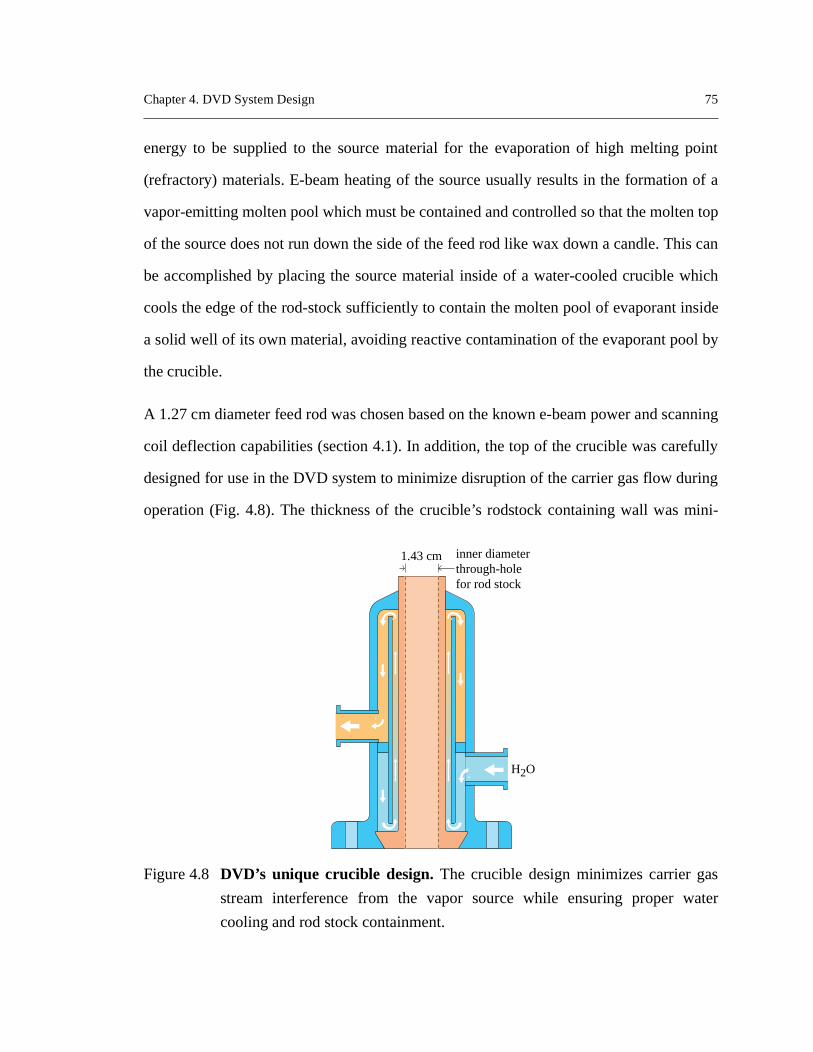
A 1.27 cm diameter feed rod was chosen based on the known e-beam power and s
coil deflection capabilities (section 4.1). In addition, the top of the crucible was care
designed for use in the DVD system to minimize disruption of the carrier gas flow du
operation (Fig. 4.8). The thickness of the crucible’s rodstock containing wall was m
Figure 4.8 DVD’s unique crucible design. The crucible design minimizes carrier ga
stream interference from the vapor source while ensuring proper w
cooling and rod stock containment.
1.43 cm inner diameterthrough-holefor rod stock
H2O
Chapter 4. DVD System Design 76
sent a
gion
drical
cible
H) to
e cen-
-acti-
was
of the
rroflu-
otion
d pin-
.9).
active
ed with
tami-
aterial
ned to
0). In
d to be
pres-
mized and raised above the main portion of the water-cooled crucible so as to pre
minimum cross-section to the gas flow. Sufficient cooling to this exposed crucible re
was ensured by machining the entire center section of the crucible from one cylin
piece of copper placed directly in contact with chilled cooling water. (For detailed cru
design drawings, see Appendix A.)
The DVD system crucible was constructed by Strohecker, Inc. (East Palestine, O
allow a 1.27 cm diameter rod of source material to be fed continuously up through th
ter of the water-cooled, copper crucible. An Aerotech, Inc (Pittsburgh, PA) computer
vated motor (model 140SMP) and multitasking motion controller (Unidex 100)
located outside the chamber and used to push the source material up to the top lip
crucible. The motor’s rotary action was fed into the processing chamber using a Fe
idic, Inc. (Nashua, NH) model SS250CFCB rotary motion feedthrough. The rotary m
of the motor and feedthrough were converted to a translational motion via a rack an
ion gearing arrangement inside the chamber, directly beneath the source rod (Fig. 4
4.4 Gas System
In the DVD system, the evaporated source material will be entrained in an inert or re
gas flow and transported towards a substrate. One of the major concerns associat
low vacuum processing, which was noted in the Background section, is potential con
nation of deposited films as a result of the gas in the chamber. To ensure that pure m
films could be created using DVD technology, a gas introduction system was desig
minimize the concentration of carrier gas born contaminants in the system (Fig. 4.1
addition to ensuring that gas introduced into the system was pure, the gas system ha
capable of regulating the rate of gas flow through the system and controlling the gas
sure ratio between the mixing and processing chambers.

Chapter 4. DVD System Design 77
linders
to the
that
ion or
ttles,
rs, the
erating
rt per
urce
To ensure uncontaminated deposits, high purity (99.999% pure) compressed gas cy
of helium or argon were selected as the initial source of the carrier gas introduced in
system. While this gas purity level is reasonably good, many applications require
moisture and oxygen contamination levels be reduced to the level of parts per mill
parts per billion to ensure quality material creation [5]. Thus, after leaving the gas bo
further cleansing of the gas flow was undertaken. From the compressed gas cylinde
carrier gas was conducted through stainless steel tubing and into a continuously op
purification (gettering) system to reduce oxygen and moisture levels below one pa
Figure 4.9 Transfer of mechanical motion into the process chamber. This
electromechanical configuration allows the position of the evaporant so
material to be controlled from a central computer.
Crucible
H2O
H2O
Cu
Rack andpinion drive
Ferrofluidicfeedthrough
Flexiblecoupling
Steppermotor
Motorcontroller
Control computerrunning LabViewTM

Chapter 4. DVD System Design 78
emi-
ically
puri-
lled to
reac-
to a
billion and total impurity levels into the low parts per thousand million range. The S
Gas Systems (San Jose, CA) model L-2000 purifier utilizes beaded, porous, chem
stable organometallic polymers that irreversibly bind to a variety of vapor-phase im
ties to produce a clean gas flow. At present a purification system has not been insta
remove moisture or other contaminants (e.g. carbon monoxide, carbon dioxide) from
tive carrier gases (e.g. oxygen).
Figure 4.10 A schematic showing the DVD system configuration. In the low vacuum
DVD system, electron beam evaporated source material is transferred
substrate by a directed gas flow entering the chamber through a nozzle.
Continuoussource feed
Differentialpump
High vacuumpump
Vaporizedsource
materialCrucible
Carriergas
streamHeater
Electron beam
Electron gun
Mechanicalchamber
pump
Compressedcarrier gascylinder
Mixingchamber
Pressuregauge
Purificationsystem
Pressuregauge
Massflow
controller
Throttleplate
NozzleFibersor flat
substrate
10 - 1500 Pa(~ 0.1 - 10 Torr)
1 - 700 Pa(~0.01 - 5 Torr)

Chapter 4. DVD System Design 79
ystem
estab-
ntrol
ontrol
Inc.
ough
w
uld be
647B
by
minar
or a
sary to
aters to
profile
are
rties,
ylinder
valves
liters
del
d to
paral-
Having established a means of gas purification, the rate of gas introduction into the s
had to be precisely regulated so that repeatable experimental conditions could be
lished. To control gas flow rates, a parallel array of computer-activated mass flow co
valves was inserted into the gas feed line of the DVD system. The mass flow c
valves and their accompanying multigas controller were purchased from MKS,
(Andover, MA) since this system allowed up to eight flow valves to be regulated thr
one controller. Although only two flow valves were initially installed, additional flo
valves for other (reactive) gases or for second and third evaporation sources co
installed in parallel at a later time if needed.
The flow valves were calibrated for helium and argon and monitored by a model
MKS multigas controller. Mass flow rates were determined within the flow valves
measuring the heat required to maintain an elevated temperature profile along a la
flow sensor tube built in parallel to the main laminar flow of gas through the valve. F
specific flow meter range and gas species, flow is proportional to the voltage neces
maintain a constant temperature profile. The MKS sensing technique uses three he
create a known temperature profile along the sensor tube, and then maintains that
during gas flow by means of an auto-balancing bridge circuit [201]. Argon and helium
sensed identically by the flow valves due to their similar thermal conduction prope
and thus combinations of the two gasses from a precisely mixed compressed gas c
can be passed through the flow valves and simultaneously regulated. The two
installed for use with the e-beam evaporation source can control up to 10 standard
per minute1 (slm) and 200 slm of gas flow respectively. While the 200 slm valve (mo
1562A) is rated to control flows as low as 3 slm, its flow control at this level was foun
fluctuate too much to provide constant experimental flow conditions, necessitating
1 standard liter - one liter of any gas at atmospheric pressure and room temperature.

Chapter 4. DVD System Design 80
nts.
s low
ech-
e ratio
2.2.3.,
er con-
teracts
es in
ment.
ozzle
r Mach
e pro-
s flow
cham-
f the gas
riable
m vac-
educed
was
re thestitut-
lel installation of the 10 slm valve (model 1259C) for use in low gas flow experime
Installation of this second flow valve made possible the precise control of gas flows a
as 0.1 slm.
After purifying and regulating the gas flow through the DVD system, an additional m
anism had to be incorporated into the system design to allow variation of the pressur
between the mixing and processing chambers (Fig. 4.10). As explained in section
the ratio of gas pressures between the mixing chamber and the processing chamb
trols the carrier gas jet velocity as it travels through the processing chamber and in
with the substrate. An ability to change carrier gas velocity could correlate to chang
vapor transport and deposition characteristics affecting material property develop
While fluid dynamics studies [116] have shown that the velocity in the throat of the n
can be at most sonic (Mach number, M = 1), the carrier gas accelerates to a highe
number and velocity, as predicted by equations (2.19) and (2.20), upon entering th
cessing chamber if flow at the throat is choked1. The maximum flow velocity attained
depends upon the exact pressure ratio reached in the system.
In the DVD system (c.f. Fig. 4.10), two subsystem components were added to the ga
system to make possible variation of the carrier gas velocity. To change the mixing
ber/processing chamber pressure ratio, either nozzles can be attached to the end o
flow tube leading from the mixing chamber into the processing chamber or a va
position throttle plate, located between the processing chamber and the main syste
uum pump, can be opened and closed. The nozzles allow the gas flow tube to be r
from a maximum diameter of 2.2 cm. The mixing chamber / nozzle assembly
1 choked flow - the type of fluid flow that occurs through a minimum area region (i.e. a nozzle) whepressure ratio (mixing chamber / throat) is greater than or equal to that given by subing M = 1 into equation (2.19).

Chapter 4. DVD System Design 81
onald
were
signed
was
intain
essing
ortions
lied by
nozzle
rr) was
feren-
-
uum
ity =
imal
rds
pack-
acity
am
n plug
a, PA)
designed by Hill [202], based upon design concepts presented in Fox and McD
[116], and built by MDC (Hayward, CA). The nozzles designed for the system
straight orifice nozzles designed by Ratnaparkhi [203] as opposed to specially de
converging or converging / diverging nozzles. The variable position throttle plate
manufactured by GNB Corporation (Hayward, CA).
4.5 Vacuum Pumps
Critical to the proper operation of the DVD system are the vacuum pumps which ma
the proper vacuum levels in the e-beam gun and pull the carrier gas through the proc
chamber at the necessary rates. Pumps for the high vacuum and medium vacuum p
of the e-beam gun were selected based upon pumping capacity specifications supp
F.E.P. The chamber pumping capacity required to create a supersonic jet for a
diameter up to 2.2 cm in chamber pressure between 1 Pa and 650 Pa (~0.01 - 5 To
determined by Hill [202] using isentropic flow calculations (Appendix A).
In the DVD system constructed for this dissertation, the e-beam gun employs a dif
tially pumped gun column to generate an electron beam in a 10-8 Pa pressure zone evacu
ated by a Balzer (Hudson, NH) TPH330 double flow standard turbomolecular vac
system in series with a Varian (Lexington, MA) SD300 roughing pump (total capac
22,200 l/min @ 10-7 Pa). Once created, the electron beam is transmitted with min
energy loss down the gun column into a 10-4 Pa pressure region evacuated by an Edwa
High Vacuum, Inc. (Poughkeepsie, NY) Model EH500 mechanical booster pumping
age (a Roots type blower) in combination with an Edwards Model E2M80 (total cap
= 8500 l/min @ 10-4 Pa) direct drive, sliding vane type vacuum pump. Finally, the be
emerges into the evaporation chamber through the hole in the replaceable tungste
where experimental pressure conditions are maintained by a Stokes (Philadelphi

Chapter 4. DVD System Design 82
1
dry,
of the
thesis
e Mach
affect
mixing
chosen
s gases
n the
uum
dwards
a and
accu-
te read-
D
e more
un oper-
high
vac-
Model 1722 (total capacity = 30,000 l/min @ 10-2 Pa) blower package (a Model 412H1
rotary oil-sealed pump in combination with a Model 615-1 positive displacement,
high-vacuum booster).
4.6 Vacuum Gauges
Correct reporting of the vacuum pressures in the mixing and processing chambers
DVD system is critical for assessing and controlling the vapor-phase material syn
capabilities of the DVD system. These pressures and pressure ratios determine th
number and velocity throughout the carrier gas flow, process parameters likely to
material property development. To ensure accurate pressure measurement in the
and process chambers, the three gauges mounted in this portion of the system were
to be gas independent capacitance manometer gauges which allow various proces
to be utilized during film synthesis without gauge recalibration. The two gauges o
mixing chamber and gas inlet tube are Leybold-Inficon (L.I.) model CDG100 vac
gauges (East Syracuse, NY) while the gauge on the processing chamber is an E
High Vacuum, Inc. model 622AB. All three gauges can read pressures between 1 P
10 KPa (~10-2 and 100 Torr). While the L.I. capacitance manometer gauges provide
rate readings at or near room temperature, the Edwards gauge guarantees accura
ings at gas temperatures up to 200oC (temperatures possibly generated by the DV
process and heater lamp warming of the gas).
In addition to the three gauges mounted on the mixing and process chambers, thre
pressure measurement gauges mounted on the e-beam gun helped ensure proper g
ation by allowing pressures in the differentially pumped lower gun region and the
vacuum filament region to be monitored. E-beam gun specifications dictate that the
uum level in the high vacuum portion of the system be better than 6.0 x 10⁻⁴ Pa (~5 x 10⁻⁶
Chapter 4. DVD System Design 83
ion is
ith a
ent is
stead,
sure in
nt as
h vac-
h-vac-
hamber
m hole
cessive
ecked
n read
L.I.
f being
esired
e, the
four
ower
roller,
Torr) for proper bolt and wire cathode operation (section 2.1.3.). Pressure in this reg
monitored using a L.I. thermocouple-type vacuum gauge (model TR901) in concert w
L.I. cold cathode vacuum gauge (model 850-610-G2). The dual gauge arrangem
required by the cold cathode gauge’s inability to operate at atmospheric pressure. In
it must be activated by the pressure reading of the thermocouple gauge after pres
the high vacuum portion of the system drops below 1.9 x 10⁻² Pa (~10-4 Torr). The cold
cathode gauge can read pressures as low as 1x10⁻⁵ Pa (~10-7 Torr). Monitoring pressure in
the gun is important to prevent damage to the gun or contamination of the filame
described in section 2.1.3. The two most likely reasons that the pressure in the hig
uum portion of the gun could be too high are that the cross-valve separating the hig
uum region from the rest of the system has been opened before the processing c
has been evacuated to processing pressure levels (0.001 - 5 Torr) and that the 2.5 m
in the tungsten plug at the bottom of the gun has been eroded and enlarged by ex
contact with the e-beam. Pressure in the medium vacuum portion of the gun is ch
using another L.I. thermocouple gauge (model TR 901). The thermocouple gauge ca
pressures as low as 1x10⁻² Pa. Readings from all six gauges were monitored by two
digital readouts, models CM3 and CC3, capable of reading three gauges each and o
easily interfaced with a computerized data acquisition system.
4.7 Substrate Temperature Control System
As noted in Chapter 2, substrate temperature can be critical to the development of d
material properties. To provide flexibility in adjusting the temperature of the substrat
DVD system was equipped with a temperature control system consisting of up to
Research, Inc. (Minneapolis, MN) heaters (model 5305-02) in combination with a p
supply (model 609), an Omega (Stamford, CT) model CN76000 temperature cont
Chapter 4. DVD System Design 84
ting 10
mov-
operly
fairly
s. The
r user
enti-
h had
ent in
to effi-
hoose
troller)
based
Serial
a dedi-
knows
er of
con-
can
ave to
and an Omega type J thermocouple. Each heater lamp has the rated ability of projec
kW/linear meter onto a substrate 3.81 cm in front of the lamp. In a chamber without
ing gas, these lamps could heat a substrate in excess of 1100oC. However, for gas flows
between 1 and 20 slm, experiments in the flowing gas DVD system showed that pr
tuned lamps could heat a flat metal substrate to just above 600oC.
4.8 Computer Control Methodology
The Directed Vapor Deposition system described in this dissertation represents a
sophisticated material synthesis tool comprised of numerous complicated subsystem
individual monitoring and control of each subsystem was not deemed to be a safe o
friendly mode of system operation. In addition, centralized computer control was id
fied as a way to facilitate data collection and minimize the number of consoles whic
to be monitored, allowing the system operator to concentrate upon the experim
progress. Development of a central operator / system interface was deemed critical
cient system operation. Thus, every effort was made during system design to c
equipment (e.g. vacuum gauges, gas controllers, motor controllers, e-beam gun con
which would make possible computer control of the DVD system.
Equipment manufacturers offered either serial or parallel interfaces for computer-
system monitoring and control. Both interfaces have strengths and weaknesses.
interfaces (e.g. RS-232, RS-485) can be hardware intensive since they must have
cated cable and interface unit installed in the control computer so that the computer
from which device the signal is coming. If the control computer has a limited numb
interface board “interrupts” available, the complexity of the system which can be
trolled is limited. However, if sufficient hardware is available, serial connections
make possible rapid monitoring and control since the host computer does not h

Chapter 4. DVD System Design 85
onent
unica-
erface
(2
com-
rdware
forma-
ng the
each
, the
make
ser /
ed out
determine which device is transmitting data. It already knows which system comp
sends information to each dedicated serial board.
Parallel interfaces (e.g. IEEE-488.2 or GPIB) represent a more sophisticated comm
tion interface since the IEEE standard specifies that all transmissions over its int
should include five bits of address information. This allows a total of thirty two 5)
devices to communicate over one interface line and computer interface board (i.e. 1
puter plus 31 external devices). While this arrangement decreases the amount of ha
necessary for system interfacing, it limits control speed somewhat since address in
tion must be sent with each signal and only one system component can send alo
cable at any given time. Table 4.2 records the communications specification for
major piece of control equipment in the DVD system. For the current DVD system
desired sampling rate was only about 1 sample / second, a rate sufficiently slow to
the IEEE-488 system configuration attractive.
In addition to the selection of hardware for computer / DVD system interfacing, a u
computer software interface also had to be selected. DVD system control was carri
Table 4.2: Computer interface information for DVD system components
Equipment Manufacturer Model Interface Type
Electron Beam Gun
F.E.P. HPE 10/60 RS-232
Gas Flow Controllers
MKS 647B multigas controller IEEE-488
Vacuum Gauges
Leybold Inficon,Edwards High
Vacuum
CM3 or CC3 digital readout
IEEE-488
Source Feed Motor
Aerotech Unidex 100 multitasking motion controller
IEEE-488
Heater Lamps / Thermocouple
Omega CN76000 Temperature Controller
RS-485

Chapter 4. DVD System Design 86
-
Lab-
tem
hange
versus
Lab-
type
ng,
using National Instruments’ LabVIEWTM software version 3.0 running under MS Win
dows v.3.11 on a Gateway2000 486 CPU / 66MHz computer with 24 Mb of memory.
VIEWTM allowed creation of a graphical user interface (GUI) from which the sys
operator can specify the file to which to save experimental run data, set gas flows, c
e-beam powers, dictate motor actions, and observe real time graphs of pressure
time data helpful in monitoring each experimental run (Fig. 4.11). Behind the GUI,
VIEWTM provided an object-oriented programming environment in which flow chart
Figure 4.11 The graphical user interface developed for the DVD system. The
LabVIEWTM front panel makes possible centralized DVD system monitori
data acquisition, and open-loop control.
Chapter 4. DVD System Design 87
control
h the
PC
n per-
ing the
wer of
routine
urrent
t most
in
user
which
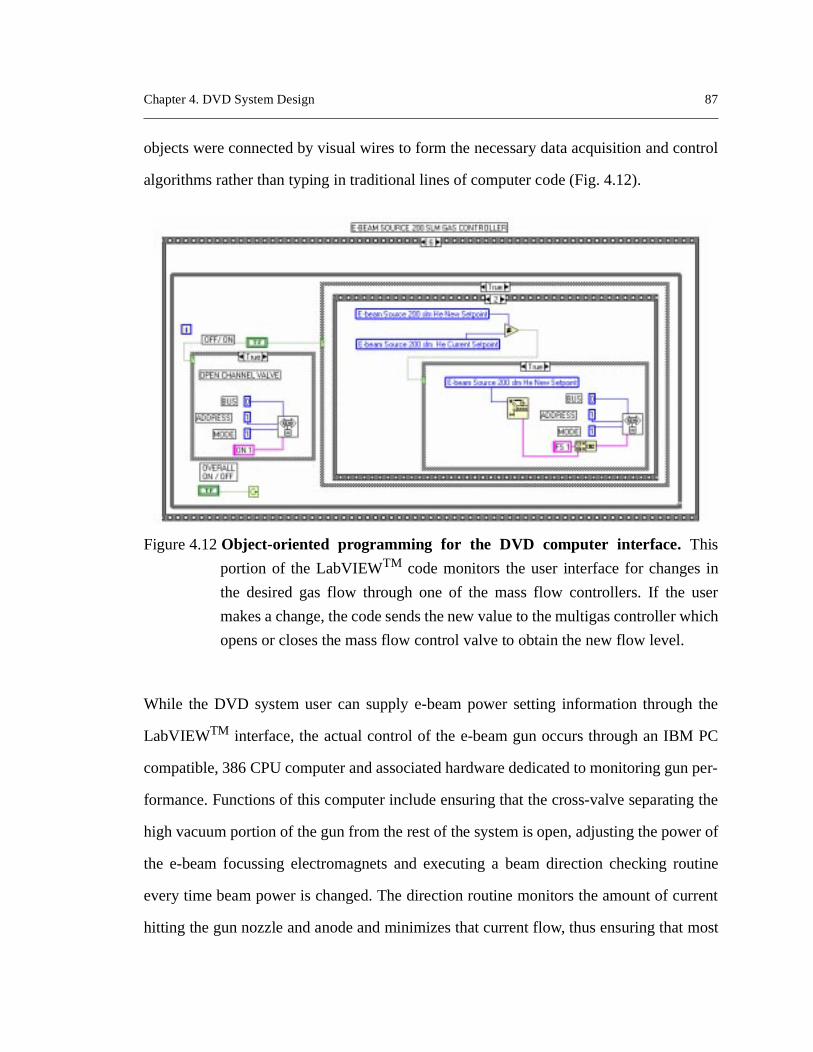
objects were connected by visual wires to form the necessary data acquisition and
algorithms rather than typing in traditional lines of computer code (Fig. 4.12).
While the DVD system user can supply e-beam power setting information throug
LabVIEWTM interface, the actual control of the e-beam gun occurs through an IBM
compatible, 386 CPU computer and associated hardware dedicated to monitoring gu
formance. Functions of this computer include ensuring that the cross-valve separat
high vacuum portion of the gun from the rest of the system is open, adjusting the po
the e-beam focussing electromagnets and executing a beam direction checking
every time beam power is changed. The direction routine monitors the amount of c
hitting the gun nozzle and anode and minimizes that current flow, thus ensuring tha
Figure 4.12 Object-oriented programming for the DVD computer interface. This
portion of the LabVIEWTM code monitors the user interface for changes
the desired gas flow through one of the mass flow controllers. If the
makes a change, the code sends the new value to the multigas controller
opens or closes the mass flow control valve to obtain the new flow level.
Chapter 4. DVD System Design 88
e gun
ive, the
while
coils.
through
lished
an
sively
urrents
field in
ing will
f the
4.13),
valuate
rocess
ution,
of the beam’s electrons are flowing out through the 2.5 mm hole in the bottom of th
and into the processing chamber. If the nozzle or anode currents become excess
control computer automatically reduces the beam power to its lowest possible level
it attempts to correct the problem by varying the strength of the e-beam positioning
Once low nozzle and anode current readings are achieved (i.e. the beam is passing
the hole in the bottom of the gun), beam power is cycled back to the setting estab
through the LabVIEWTM front panel. The usual cause of a high anode current is
improperly assembled Wehnelt cup assembly. The most likely cause of an exces
high nozzle current is beam spreading caused by use of incorrect beam focussing c
(Fig. 4.3) or too high a chamber pressure. Once the strength of the electromagnetic
the focussing coils is adjusted or the chamber pressure is reduced, beam spread
diminish and the majority of the beam will pass through the opening in the bottom o
gun, allowing material synthesis to resume.
4.9 Concluding Remark
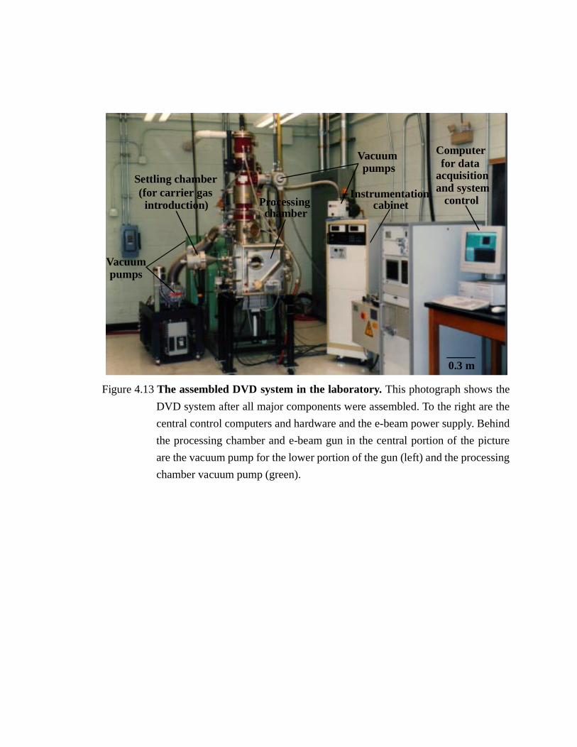
Having constructed the e-beam powered Directed Vapor Deposition system (Fig.
experiments could now be conducted and models of vapor transport developed to e
the system’s performance and to provide insight into how changes to the system’s p
variables affected vapor transport in the system, particularly vapor adatom distrib
deposition efficiency, kinetic energy, and angle of incidence.
e the
ehind
icture
sing
Figure 4.13 The assembled DVD system in the laboratory. This photograph shows the
DVD system after all major components were assembled. To the right ar
central control computers and hardware and the e-beam power supply. B
the processing chamber and e-beam gun in the central portion of the p
are the vacuum pump for the lower portion of the gun (left) and the proces
chamber vacuum pump (green).
Settling chamber
Processingchamber
Computerfor data
acquisitionand system
controlInstrumentation
cabinet
Vacuumpumps
(for carrier gasintroduction)
Vacuumpumps
0.3 m