chapter 3b. pavement and curb markings section … · blue raised reflective pavement markers, may...
TRANSCRIPT

MUTCD 2003 California Supplement Page 3B-1
May 20, 2004
CHAPTER 3B. PAVEMENT AND CURB MARKINGS
Section 3B.01 Yellow Centerline Pavement Markings and WarrantsThe following is added to this section:Standard:
Centerline patterns shall be selected from those shown in Figures 3A-101 and 3A-104. Raised retroreflective pavement markers shall be used to supplement the centerline markings on
State highways, except in snow areas.Support:
Refer to CVC 21460 for Double Lines.Refer to CVC 21460.5 for Two-Way Left-Turn Lanes.
Standard:A left edge line shall consist of a solid 100 mm (4 in) wide yellow line, yellow reflective pavement
markers or a combination of line and markers as shown in Figure 3A-105.Option:
Two normal solid yellow lines may be used as a left edge line on a divided roadway for more emphasiswhen motorists tend to use the shoulder for a through lane or where encroachments onto the shoulderoccasionally occur.Support:
Left edge line patterns for median islands are shown in Figure 3A-107.
Figure 3B-2. Examples of Four-or-More Lane, Two-Way Marking ApplicationsStandard:
Lane-use arrow markings shown in this figure as optional, shall not be optional but required. SeeSection 3B.19.
Section 3B.02 No-Passing Zone Pavement Markings and WarrantsStandard:
Paragraph 3 (“Where the distance…”) is deleted and replaced with the following:If the gap between successive no-passing zones is less than the sight distance for the prevailing
speed shown in Table 3B-1, the no-passing zone shall be continuous.The following is added to this section:Support:
Refer to CVC 21750 through 21759 for overtaking and passing.Refer to CVC 21460 for Double Lines.CVC 21752 restricts passing (driving on left side of a two-way roadway) when approaching within 30 m
(100 feet) of or when traversing any intersection or railroad grade crossing. CVC 21752 also restrictspassing (driving on left side of a two-way roadway) when the view is obstructed upon approaching within 30m (100 feet) of any bridge, viaduct, or tunnel. The patterns and policy for intersection markings are shownin Figure 3A-109.Standard:
No-passing zone patterns shall be selected from those shown in Figures 3A-103 and 3A-104. Guidance:
The no-passing zone markings at intersections, when used, should be between 30 m (100 ft) and 90 m(300 ft) in length at the approach to an intersection and placed in a pattern as shown in Figure 3A-109.
Section 3B.03 Other Yellow Longitudinal Pavement MarkingsOption:
In Paragraph 5 (“Signs should be…”), the word “should” is changed to “may”.

MUTCD 2003 California Supplement Page 3B-2
May 20, 2004
The following is added to this section:Standard:
On State highways, reversible lanes shall be separated by physical barriers or delineators.Support:
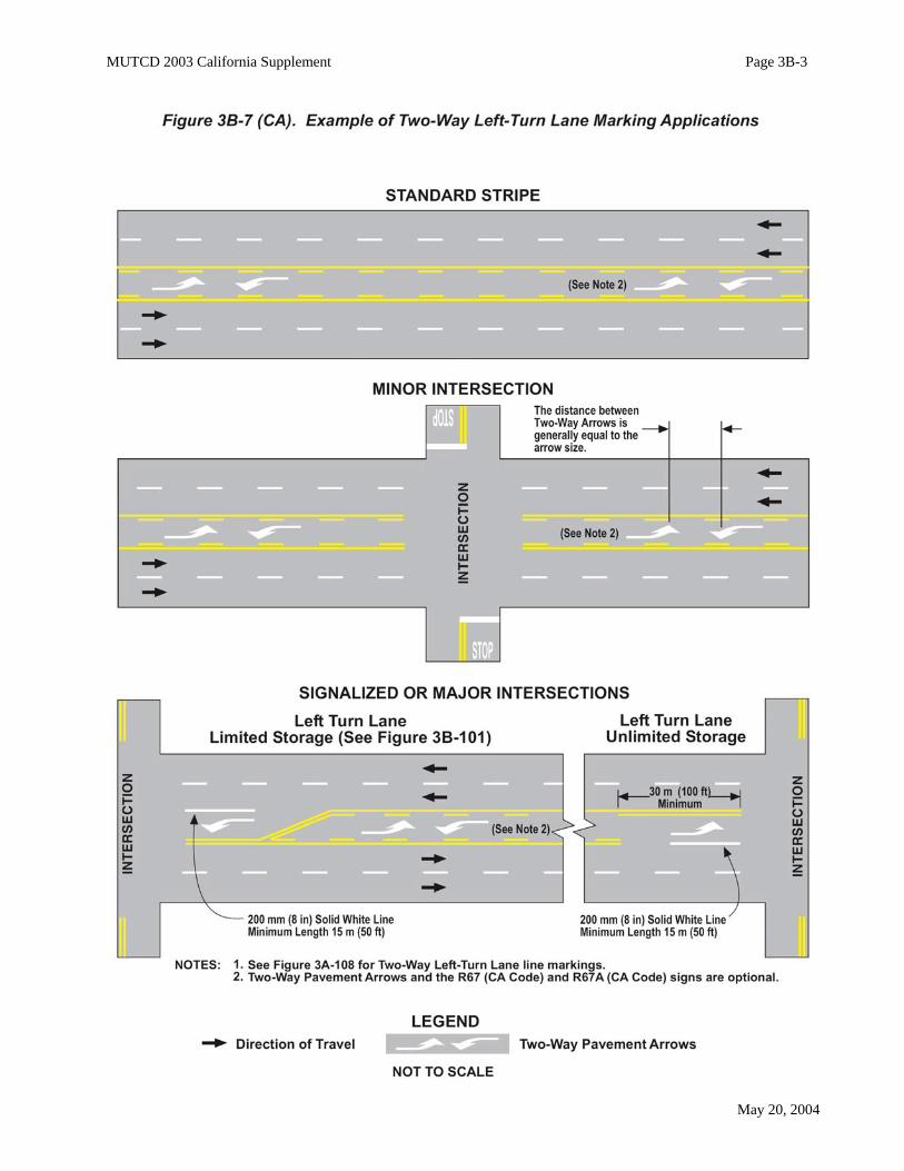
A two-way left-turn lane is a lane reserved in the center of a highway for exclusive use of left or U-turning vehicles. Refer to CVC 21460.5. It is normally used where there are many points of access.Standard:
The two-way left-turn lane markings shall be selected from those shown in Figure 3A-108. Option:
Optional treatments at signalized, major and minor intersections as shown in Figure 3B-7 (CA) may beused.
Two-way opposing pavement arrows may be used as shown in Figure 3B-7 (CA). The arrows may besupplemented by Two-Way Left Turn Lane (CA Code R67) sign at new installations and problem locations.Guidance:
A gap in the markings should be made at all intersections.Support:
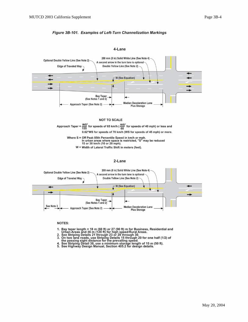
For left turn channelization, see Figure 3B-101 and Department of Transportation’s Highway DesignManual, Section 405.2. See Section 1A.11 for information regarding this publication.
Section 3B.04 White Lane Line Pavement Markings and WarrantsThe following is added to this section:Standard:
Lane line patterns shall be selected from those shown in Figure 3A-102. Detail 9 or 10 (65 km/h(40 mph) or less) or Detail 12 or 13 (70 km/h (45 mph) or more) shall be used on State freeways,expressways, freeway ramps, freeway to freeway connectors and collector roads, except when used insnow areas, the raised pavement markers will be recessed.
A right edge line shall consist of a solid 100 mm (4 in) wide white line. Guidance:
The edge line should be placed 50 mm (2 in) in from the edge of traveled way, approximately 3.6 m (12ft) from the lane line or centerline on highway mainlines, ramps, and connectors. See Figure 3A-106.
Generally, the solid edge line should be dropped at the beginning of intersection flares. Option:
In heavy fog areas, or locations where additional guidance would be beneficial, a dotted 100 mm (4 in)wide white right edge line may be continued across an intersection. Support:
Edge line is not used at turnouts. See Figure 3B-108.
Section 3B.05 Other White Longitudinal Pavement MarkingsStandard:
In Paragraph 7 (“For Exit ramps…”), the second sentence (“With a parallel…”) is deleted andreplaced with the following:
With a parallel deceleration lane, a 200 mm (8 in) wide dotted white lane drop line shall beextended from the beginning of the channelizing line upstream of the entire length of the full-widthdeceleration lane.
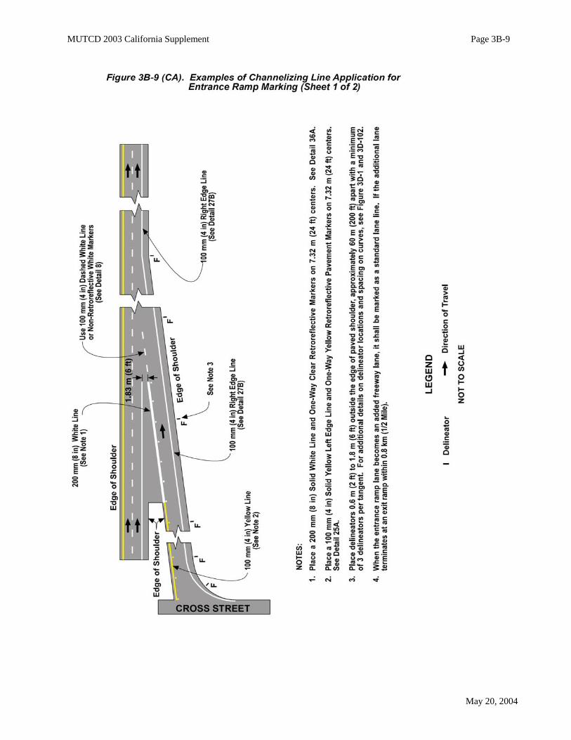
In Paragraph 10 (“For entrance ramps with a parallel…”) the phrase “one-half the length” ischanged to “the entire length”.
In Paragraph 12 (“Lane drop markings…”) first sentence, the word “may” is changed to “shall”.
MUTCD 2003 California Supplement Page 3B-3
May 20, 2004
MUTCD 2003 California Supplement Page 3B-4
May 20, 2004
MUTCD 2003 California Supplement Page 3B-5
May 20, 2004
The following is added to Paragraph 13 (“If used, lane…”):Guidance:
If the dropped lane is an auxiliary lane 0.8 km (1/2 mi) or less in length, the lane drop line should extendthroughout the entire length. The following is added to this section:Standard:
The lane drop line pattern shall be as shown in Figure 3A-111. Support:
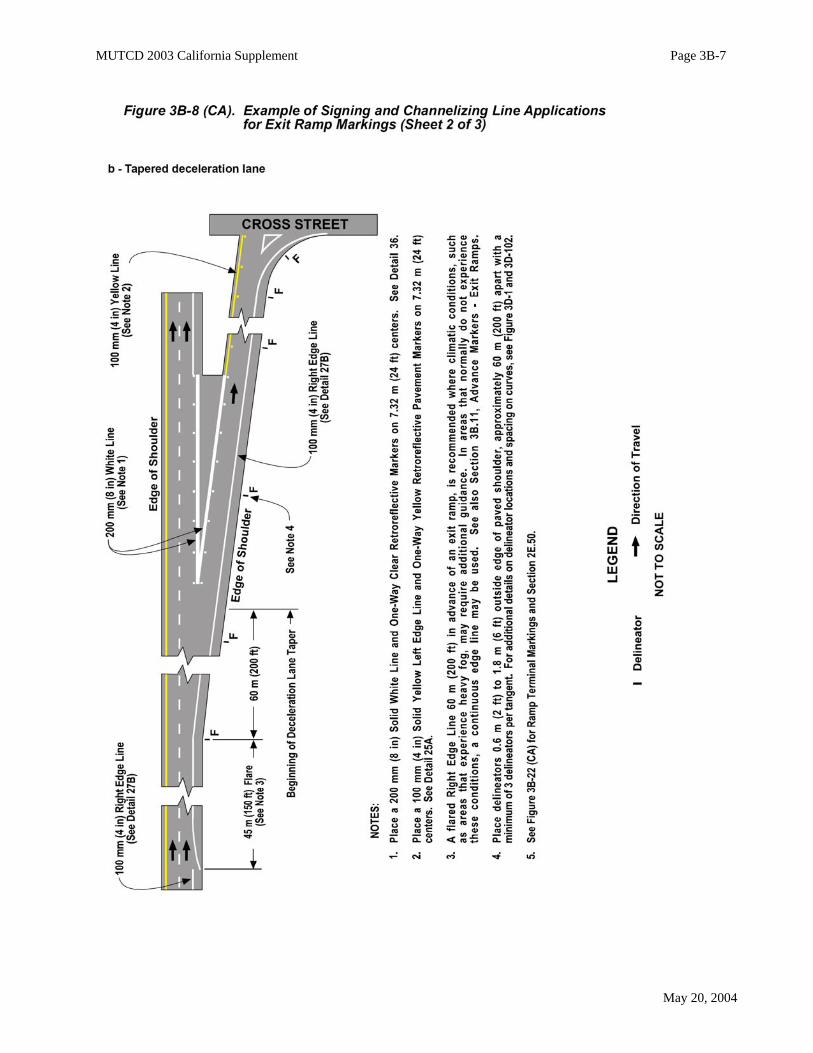
See Figures 3A-111, 3B-8 (CA), 3B-9 (CA), 3B-10 (CA), 3B-12 (CA) and 3B-107 for further details ofmarkings and signing.Option:
A 200 mm (8 in) wide single solid white line preceded by a 200 mm (8 in) wide dotted white line may beplaced in advance of an intersection where the outside lane is dropped at the intersection, and as a result,creates a mandatory turn lane.Standard:
If used, diagonal lines shall be the same color as the edge line.
Figure 3B-8. Examples of Channelizing Line Applications for Exit Ramp MarkingsStandard:
MUTCD Figure 3B-8 is deleted and replaced with Figure 3B-8 (CA).
Figure 3B-9. Examples of Channelizing Line Applications for Entrance Ramp MarkingsStandard:
MUTCD Figure 3B-9 is deleted and replaced with Figure 3B-9 (CA).
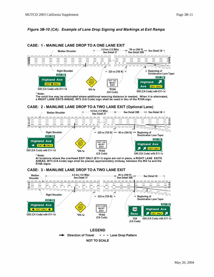
Figure 3B-10. Example of Lane Drop Markings at Exit RampsStandard:
MUTCD Figure 3B-10 is deleted and replaced with Figure 3B-10 (CA).
Section 3B.06 Edge Line Pavement Markings The following is added to this section:Standard:
Exit and entrance ramps, including freeway connectors, shall be marked with a yellow edge linesupplemented with yellow reflective pavement markers on the left and a white edge line on the right.See Figure 3A-105.
Section 3B.07 Warrants for Use of Edge LinesThe following is added to this section:Standard:
Edge lines shall be used on all State highways, except urban type streets with curbs and parkingprovisions.Option:
The Two-Way Traffic (W6-3) sign may be used in conjunction with edge lines at locations wheremotorists could perceive that they are on a one-way roadway when, in fact, they are on a two lane, two-wayhighway. See Section 2C.34 for W6-3 sign.

MUTCD 2003 California Supplement Page 3B-6
May 20, 2004
MUTCD 2003 California Supplement Page 3B-7
May 20, 2004

MUTCD 2003 California Supplement Page 3B-8
May 20, 2004
MUTCD 2003 California Supplement Page 3B-9
May 20, 2004

MUTCD 2003 California Supplement Page 3B-10
May 20, 2004
MUTCD 2003 California Supplement Page 3B-11
May 20, 2004

MUTCD 2003 California Supplement Page 3B-12
May 20, 2004
Section 3B.08 Extensions Through Intersections or InterchangesStandard:
In Paragraph 1 (“Pavement markings extended …”), the phrase “…and at least the same width…” is deleted as it conflicts with Paragraph 2 (“A normal line…”).The following is added to this section:Support:
See Figure 3A-112, Detail 40 and 40A for lane line extensions.
Figure 3B-11. Examples of Extensions through IntersectionsStandard:
MUTCD Figure 3B-11 (c) is deleted as it could mislead motorists to believe that the through lanetraffic may also turn left.
Lane-use arrow markings shown in this figure as optional, shall not be optional but required. SeeSection 3B.19.
Section 3B.09 Lane Reduction Transition MarkingsThe following is added to this section:Support:
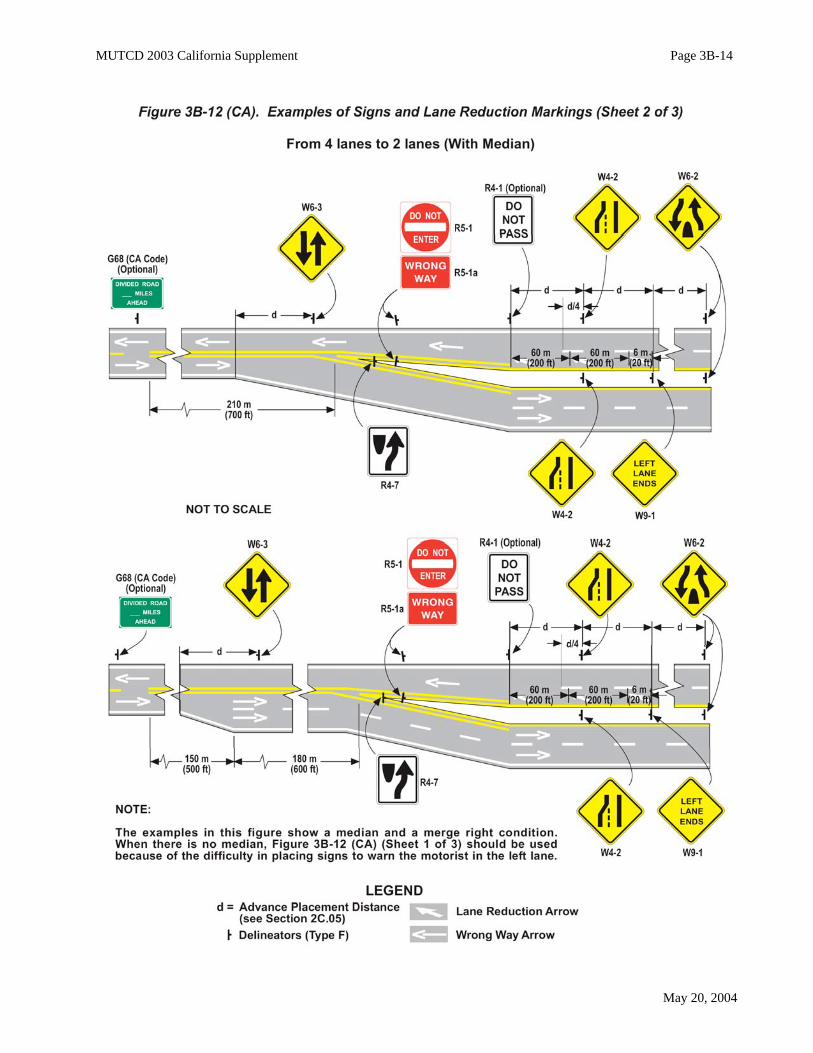
Typical lane reduction transitions (four lane to two lane) and transitions from two lanes to four lanes areshown in Figure 3B-12 (CA).
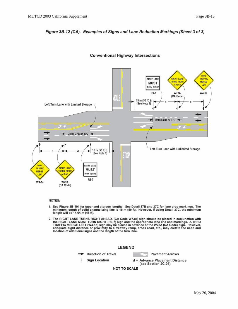
Figure 3B-12. Examples of Lane Reduction MarkingsStandard:
MUTCD Figure 3B-12 is deleted and replaced with Figure 3B-12 (CA).
Section 3B.11 Raised Pavement MarkersStandard:
The N criteria for spacing as mentioned in this section shall not be used in California. The widths and patterns of raised pavement markers shall conform to the details shown in Figures
3A-101 through 3A-112. See Section 3A.05.The following is added to this section:Support:
Raised pavement markers are not normally placed where snow plows would damage the markers andrequire an unusual amount of replacement. Guidance:
When used in these areas, they should be recessed, as shown in Department of Transportation’s StandardPlan A20-D. See Section 1A.11 for information regarding this publication.Advance MarkersOption:
Advance Markers at exit ramps may be used to help motorists locate exit ramps in heavy fog areas. Support:
The Advance Markers consist of a 3-2-1 countdown pattern of one-way clear reflective pavementmarkers. The pattern consists of three markers placed on the right shoulder 640 m (2100 ft) in advance of theneutral area (gore), two markers at 425 m (1400 ft) and one marker at 215 m (700 ft). The markers areplaced on a line perpendicular to the lane line at 0.3 m (1 ft) spacing beginning 50 mm (2 in) off the edge oftraveled way.

MUTCD 2003 California Supplement Page 3B-13
May 20, 2004
MUTCD 2003 California Supplement Page 3B-14
May 20, 2004
MUTCD 2003 California Supplement Page 3B-15
May 20, 2004

MUTCD 2003 California Supplement Page 3B-16
May 20, 2004
Location Markers for Fire HydrantsOption:
Blue raised reflective pavement markers, may be placed on a highway, street, or road, to mark firehydrant and/or water supply locations. Standard:
The blue raised reflective pavement markers shall not be used for any other purpose.Local agencies shall not place blue reflective pavement markers on a State highway unless they
first obtain an encroachment permit from the Department of Transportation. The agency responsiblefor the placement shall also be responsible for the maintenance and replacement. See Section 13060, ofthe Health and Safety Code. See Section 1A.11 for information regarding this publication.Guidance:
In general, the blue reflective pavement markers should be placed 150 mm (6 in) from the centerlinestripe, or approximate center of the pavement where there is no centerline stripe, on the side nearest the firehydrant.
When placed on expressways, freeways and freeway ramps, they should be placed on the shoulder, 0.31m (1 ft) to the right of the edge line, opposite the fire hydrant. Typical marker locations are shown on Figure3B-102.Option:
Because fire hydrants adjacent to freeways may be out of the right-of-way and, in many locations, out ofview from the freeway, some fire districts may want to install small supplemental signs (CA Code S9 andS10) or markings to identify the hydrant number or distance to the hydrant. These installations are optionaland at the discretion of the Department of Transportation’s Districts.
Section 3B.12 Raised Pavement Markers as Vehicle Positioning Guides with Other LongitudinalMarkings
Standard:The N criteria for spacing as mentioned in this section shall not be used in California. The widths and patterns of raised pavement markers shall conform to the details shown in Figures
3A-101 through 3A-112. See Section 3A.05.
Section 3B.13 Raised Pavement Markers Supplementing Other MarkingsStandard:
The N criteria for spacing as mentioned in this section shall not be used in California. The widths and patterns of raised pavement markers shall conform to the details shown in Figures
3A-101 through 3A-112. See Section 3A.05.
Section 3B.14 Raised Pavement Markers Substituting for Pavement MarkingsStandard:
The N criteria for spacing as mentioned in this section shall not be used in California. The widths and patterns of raised pavement markers shall conform to the details shown in Figures
3A-101 through 3A-112. See Section 3A.05.The following is added to this section:Standard:
If used on State highways, internally-illuminated raised pavement markers shall be installed by anencroachment permit and include a maintenance agreement as a provision of the permit for the servicelife of the markers.

MUTCD 2003 California Supplement Page 3B-17
May 20, 2004
MUTCD 2003 California Supplement Page 3B-18
May 20, 2004
Section 3B.15 Transverse MarkingsThe following is added to this section:Standard:
Crosswalk markings near schools shall be yellow. Refer to CVC 21368 and Part 7.Support:
Refer to Department of Transportation’s Standard Plans for pavement marking letters, numerals andsymbols. See Section 1A.11 for information regarding this publication
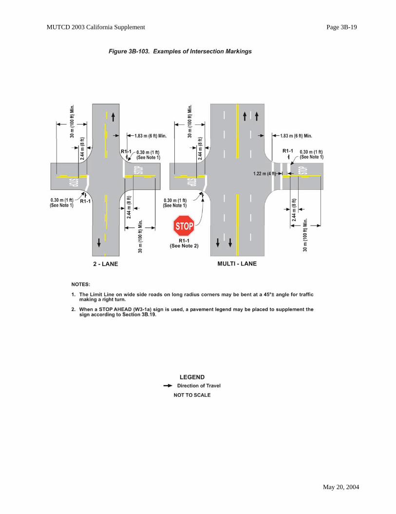
Section 3B.16 Stop and Yield LinesThe following is added to this section:Support:
As defined in CVC 377, a "limit line" is a solid white line not less than 300 mm (12 in) nor more than600 mm (24 in) wide, extending across a roadway or any portion thereof to indicate the point at which trafficis required to stop in compliance with legal requirements.Standard:
For all purposes, limit line(s) shall mean stop line(s) as referenced in the MUTCD.A limit line shall be placed in conjunction with STOP (R1-1) signs on paved approaches not
controlled by signals.Guidance:
If a sidewalk exists, the limit line should be placed in advance of an unmarked crosswalk area.Option:
A limit line may be placed in advance of a crosswalk where vehicles are required to stop, in compliancewith a STOP (R1-1) sign, traffic control signal or some other traffic control device.Support:
If a marked crosswalk is in place, it would normally function as a limit line.Typical limit line markings are shown in Figure 3B-103.
Standard:The individual triangles comprising the yield line shall have a base of 0.6 m (2 ft) wide and a height
of 0.9 m (3 ft). The space between the triangles shall be 0.3 m (1 ft).Support:
Figure 3B-14 (CA) shows typical yield line layout for streets and highways.
Figure 3B-14. Examples of Yield Line LayoutsStandard:
MUTCD Figure 3B-14 is deleted and replaced with Figure 3B-14 (CA).
Section 3B.17 Crosswalk MarkingsStandard:
In Paragraph 4 (“When crosswalk lines…”), the phrase “150 mm (6 in)” is changed to “300 mm(12 in)”.The following is added to this section:Standard:
Crosswalk markings near schools shall be yellow as provided in CVC 21368. See Part 7.Option:
Pedestrian crosswalk markings may be placed at intersections, representing extensions of the sidewalklines, or on any portion of the roadway distinctly indicated for pedestrian crossing. Refer to CVC 275.Guidance:
In general, crosswalks should not be marked at intersections unless they are intended to channelizepedestrians. Emphasis is placed on the use of marked crosswalks as a channelization device.
MUTCD 2003 California Supplement Page 3B-19
May 20, 2004

MUTCD 2003 California Supplement Page 3B-20
May 20, 2004
_______________________________________________________________________________________
The following factors may be considered in determining whether a marked crosswalk should be used:• Vehicular approach speeds from both directions.• Vehicular volume and density.• Vehicular turning movements.• Pedestrian volumes.• Roadway width.• Day and night visibility by both pedestrians and motorists.• Channelization is desirable to clarify pedestrian routes for sighted or sight impaired pedestrians.• Discouragement of pedestrian use of undesirable routes.• Consistency with markings at adjacent intersections or within the same intersection.
Option:Crosswalk markings may be established between intersections (mid-block) in accordance with CVC
21106(a). Guidance:
Mid-block pedestrian crossings are generally unexpected by the motorist and should be discouragedunless, in the opinion of the engineer, there is strong justification in favor of such installation. Particularattention should be given to roadways with two or more traffic lanes in one direction as a pedestrian may behidden from view by a vehicle yielding the right-of-way to a pedestrian.Option:
When diagonal or longitudinal lines are used to mark a crosswalk, the transverse crosswalk lines may beomitted.Standard:
However, when the factor that determined the need to mark a crosswalk is the clarification ofpedestrian routes for sight-impaired pedestrians, the transverse crosswalk lines shall be marked.Option:
At controlled approaches, limit lines (stop lines) help to define pedestrian paths and are therefore a factorthe engineer may consider in deciding whether or not to mark the crosswalk.
Where it is desirable to remove a marked crosswalk, the removal may be accomplished by repaving orsurface treatment.
MUTCD 2003 California Supplement Page 3B-21
May 20, 2004
Guidance:A marked crosswalk should not be eliminated by allowing it to fade out or be worn away.
Support:The worn or faded crosswalk retains its prominent appearance to the pedestrian at the curb, but is less
visible to the approaching driver.Standard:
Notification to the public shall be given at least 30 days prior to the scheduled removal of anexisting marked crosswalk. The notice of proposed removal shall inform the public how to provideinput related to the scheduled removal and shall be posted at the crosswalk identified for removal.Refer to CVC 21950.5Option:
Signs may be installed at or adjacent to an intersection directing that pedestrians shall not cross in acrosswalk indicated at the intersection in accordance with CVC 21106(b).
White PED XING pavement markings may be placed in each approach lane to a marked crosswalk,except at intersections controlled by traffic signals or STOP or YIELD signs.
Section 3B.18 Parking Space MarkingsThe following is added to this section:Support:
Refer to CVC 22500 through 22522 for parking space markings.Refer to Section 2B.39 for Parking Regulations.
Policy on Parking RestrictionsOption:
Local authorities may, by ordinance, provide for the establishment of parking meter zones and causestreets and highways to be marked with white lines designating parking spaces. Refer to CVC Section22508.Standard:
Where the proposed zones are on State highways, the ordinances shall be approved by theDepartment of Transportation.
Local authorities shall furnish a sketch or map showing the definite location of all parking meterstalls on State highways before departmental approval is given.Support:
The District Directors have been delegated the authority to approve such ordinances.The desirable dimensions of parking meter stalls are 2.4 m (8 ft) by 7.3 m (24 ft) with a minimum length
of 6.1 m (20 ft).Standard:
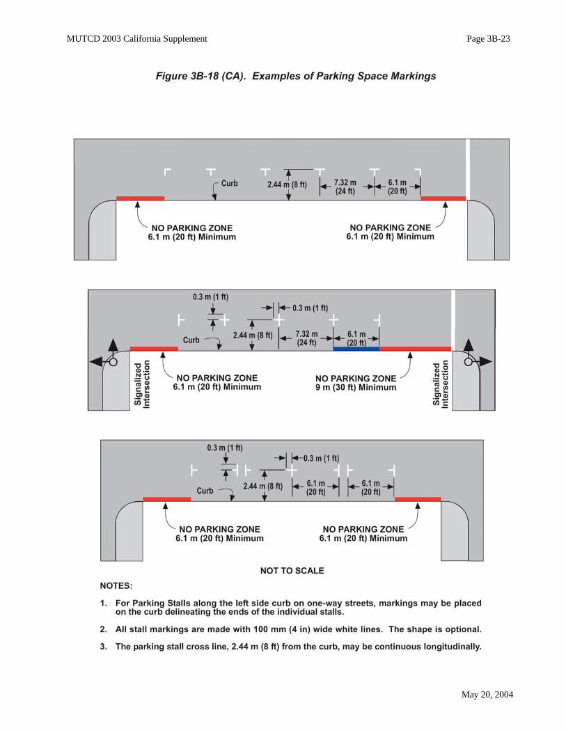
At all intersections, one stall length on each side measured from the crosswalk or end of curbreturn shall have parking prohibited. A clearance of 1.8 m (6 ft) measured from the curb return shallbe provided at alleys and driveways. Guidance:
At signalized intersections parking should be prohibited for a minimum of two stall lengths on the nearside and one stall length on the far side. See Figure 3B-18 (CA).Standard:
The departmental approval for the installation of the parking meters shall be covered by anencroachment permit.Option:
Local authorities may by ordinance permit angle parking. Refer to CVC 22503.Support:
Department of Transportation does not approve ordinances establishing angle parking on State highways.
MUTCD 2003 California Supplement Page 3B-22
May 20, 2004
Diagonal parking stalls are not permitted on State highways.
Figure 3B-18. Examples of Parking Space MarkingsStandard:
MUTCD Figure 3B-18 is deleted and replaced with Figure 3B-18 (CA).
Section 3B.19 Pavement Word and Symbol MarkingsStandard:
Paragraphs 9 (“The SCHOOL word …”) and 10 (“When the SCHOOL …”) are deleted. If used,the SCHOOL pavement marking shown in Figure 3B-20 (CA) shall be used and it shall be restricted toa single lane.Guidance:
In Paragraph 3 (“Letters and numerals…”), the phrase “1.8 m (6 ft)” is changed to “2.44 m (8 ft)”.Option:
In Paragraph 11 (“Pavement word and…”), the words “should” and “scaled” are changed to “may” and“spaced”, respectively.The following is added to this section:Standard:
Word and symbol markings near schools shall be yellow as provided in CVC 21368. See Part 7.Support:
Normally, pavement word and symbol markings supplement standard signing.Guidance:
A STOP pavement marking should be placed on all but minor approaches to State highways notcontrolled by signals.Option:
Pavement markings with appropriate figures may be used to supplement speed limit signs. See Section2B.13.
Arrows:Standard:
Where a turning movement is mandatory, an arrow marking accompanied by a regulatory signshall be used. However, when an additional clearly marked lane is provided for the approach to theturning movement, the sign is not required. Refer to CVC 22101.Support:
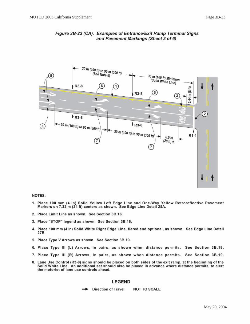
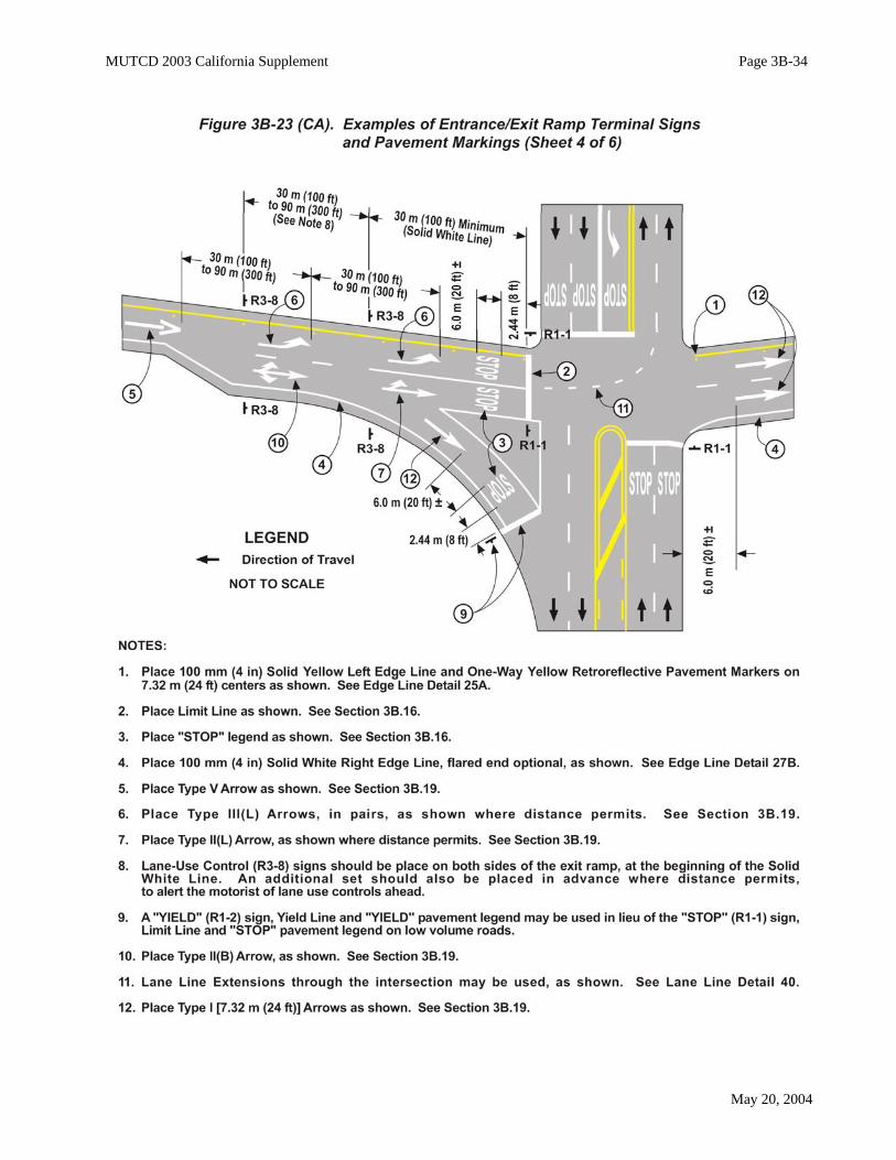
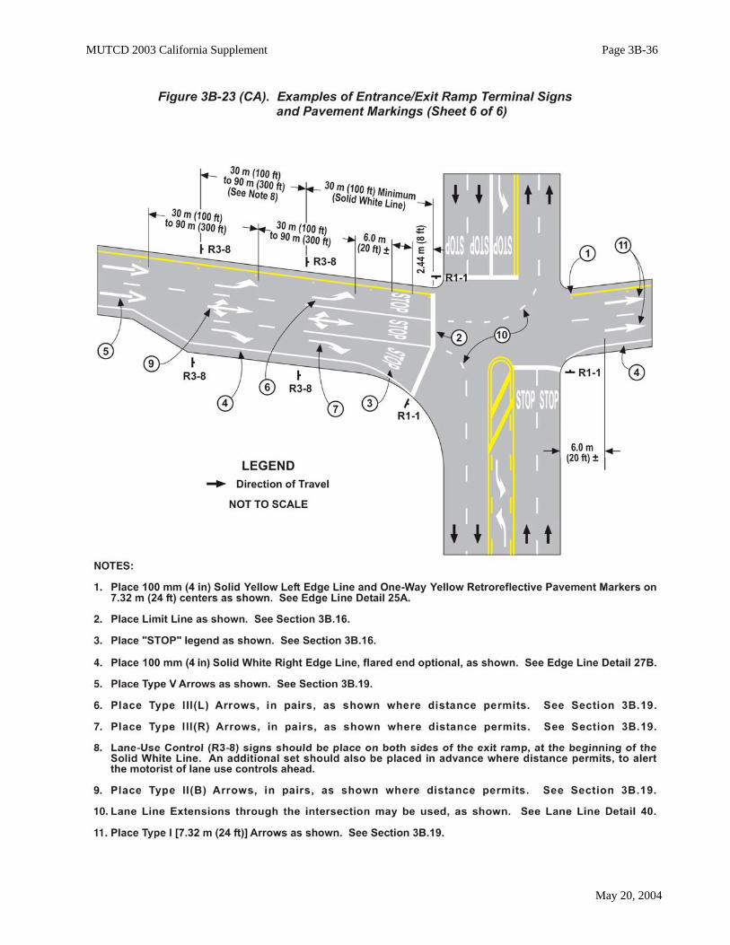
Examples of entrance/exit ramp terminal signs and pavement markings are shown in Figure 3B-23 (CA).Guidance:
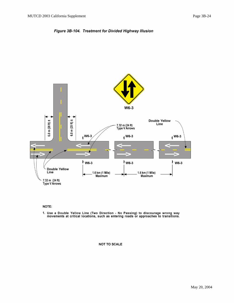
The Type V arrows and warning signs, as shown in Figure 3B-104, should be used at locations wheremotorists could perceive that they are on a one-way roadway when, in fact, they are on a two lane, two-wayhighway. Following are some typical situations:
• Construction sites where a two-lane highway is being converted to a freeway or an expressway.• Two-lane, two-way highways where ultimate freeway or expressway right-of-way has been
purchased and grading for the full width has been completed.• Two-lane, two-way highways following long sections of multi-lane freeway or expressway.
Exit Ramp Arrows:Standard:
A minimum of two pavement arrows shall be placed on each freeway exit ramp lane.A Type V arrow shall be the first arrow, on the ramp, in the direction of travel when exiting the
freeway.
MUTCD 2003 California Supplement Page 3B-23
May 20, 2004
MUTCD 2003 California Supplement Page 3B-24
May 20, 2004

MUTCD 2003 California Supplement Page 3B-25
May 20, 2004
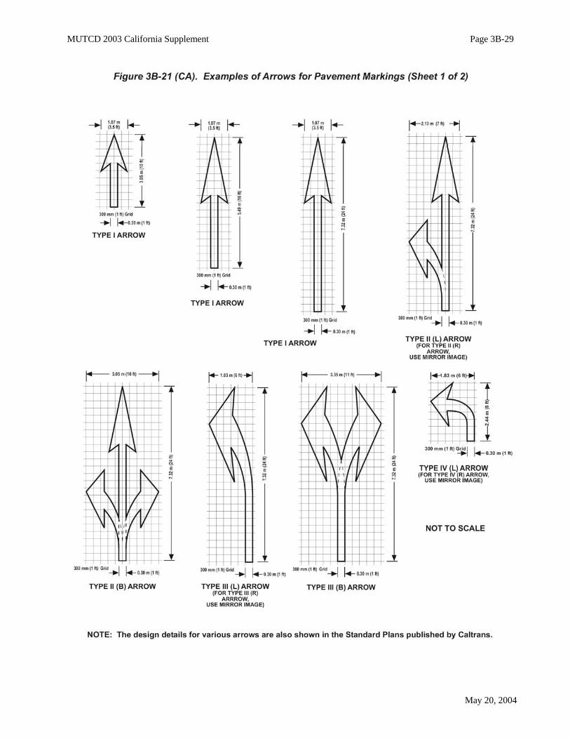
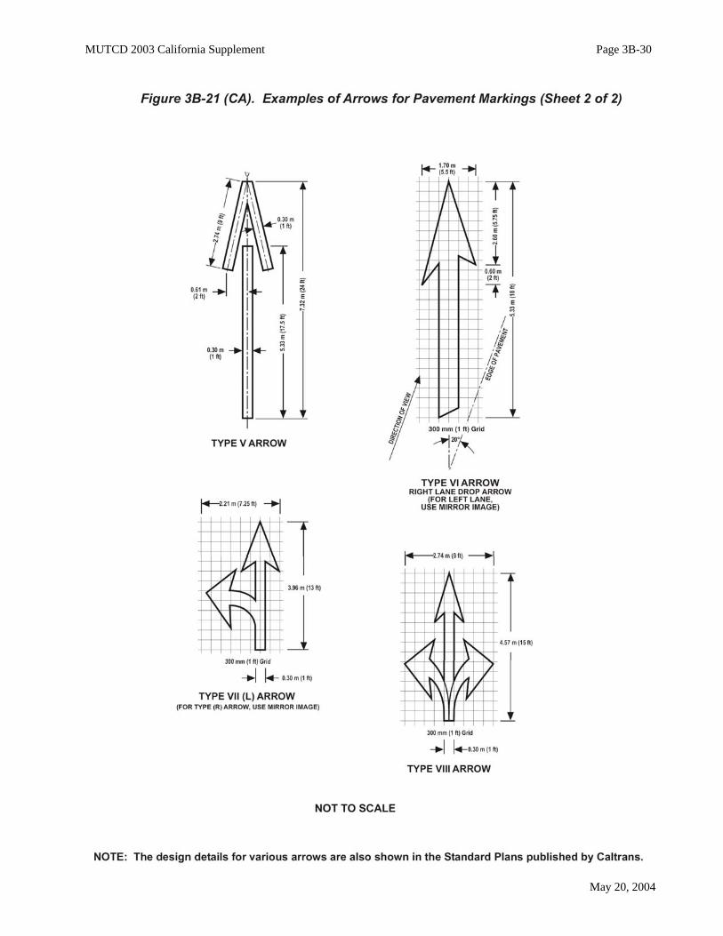
Where a mandatory movement is required, a Type I, II, III, IV, VII, or VIII arrow shall be placedwith its point approximately 6.10 m (20 ft) preceding the limit line, crosswalk or "STOP" pavementlegend. Where no mandatory movement is required, a Type V arrow shall be used at this location.
All other additional arrows, when used, shall be a minimum of 7.32 m (24 ft) in length.All arrows shall be placed in the center of the lane and spaced approximately 30 m (100 ft) to 90 m
(300 ft) apart. Guidance:
The actual position and spacing should be determined in the field to provide the optimum visibility fortraffic that may attempt to enter the exit ramp in the wrong direction.Support:
See Figures 3B-21 (CA) and 3B-23(CA).
Entrance Ramp Arrows:Standard:
A minimum of one Type I arrow, not less than 5.49 m (18 ft) in length, shall be positioned in thecenter of each freeway entrance ramp lane so that it is clearly in view of a right-way driver. Guidance:
The distance between arrows, when more than one per lane is needed, should be 30 m (100 ft) to 90 m(300 ft). The Type V arrow should not be used on entrance ramps. Support:
See Figures 3B-21 (CA) and 3B-23(CA).Additional information on signing of ramp terminals is shown in Section 2E.50.
Turn Lane Arrows:Standard:
One directional arrow, a minimum of 2.44 m (8 ft) in length, shall be placed in the center of eachturning lane near the point of entrance. Option:
High approach speeds may justify the use of a longer arrow. Two or more arrows may be placed in longturning lanes. Support:
See Figures 3B-7 (CA) and 3B-101.Support:
Refer to Section 2E.50 for Wrong-Way Traffic Control at Interchange Ramps.
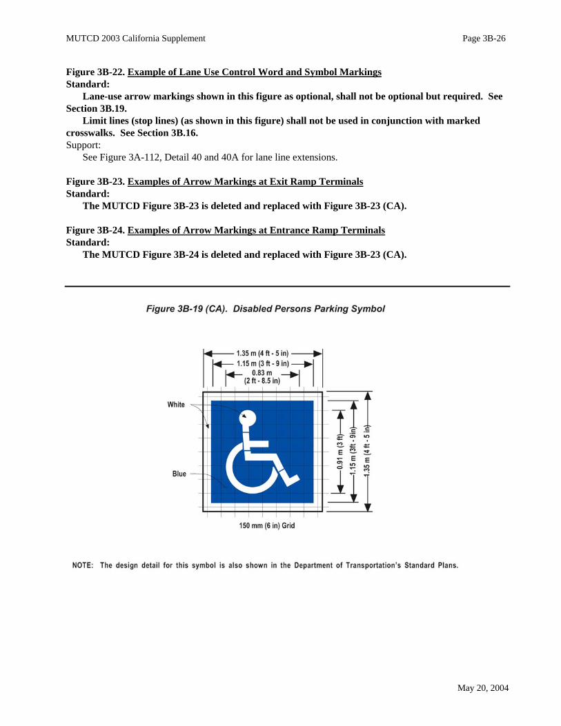
Figure 3B-19. International Symbol of Accessibility Parking Space Marking with Blue Backgroundand White Border OptionsStandard:
MUTCD Figure 3B-19 is deleted and replaced with Figure 3B-19 (CA).
Figure 3B-20. Example of Elongated Letters for Word Pavement MarkingsStandard:
MUTCD Figure 3B-20 is deleted and replaced with Figure 3B-20 (CA).
Figure 3B-21. Examples of Standard Arrows for Pavement MarkingsMUTCD Figure 3B-21 is deleted and replaced with Figure 3B-21 (CA).
MUTCD 2003 California Supplement Page 3B-26
May 20, 2004
Figure 3B-22. Example of Lane Use Control Word and Symbol MarkingsStandard:
Lane-use arrow markings shown in this figure as optional, shall not be optional but required. SeeSection 3B.19.
Limit lines (stop lines) (as shown in this figure) shall not be used in conjunction with markedcrosswalks. See Section 3B.16.Support:
See Figure 3A-112, Detail 40 and 40A for lane line extensions.
Figure 3B-23. Examples of Arrow Markings at Exit Ramp TerminalsStandard:
The MUTCD Figure 3B-23 is deleted and replaced with Figure 3B-23 (CA).
Figure 3B-24. Examples of Arrow Markings at Entrance Ramp TerminalsStandard:
The MUTCD Figure 3B-24 is deleted and replaced with Figure 3B-23 (CA).

MUTCD 2003 California Supplement Page 3B-27
May 20, 2004

MUTCD 2003 California Supplement Page 3B-28
May 20, 2004
MUTCD 2003 California Supplement Page 3B-29
May 20, 2004
MUTCD 2003 California Supplement Page 3B-30
May 20, 2004

MUTCD 2003 California Supplement Page 3B-31
May 20, 2004

MUTCD 2003 California Supplement Page 3B-32
May 20, 2004
MUTCD 2003 California Supplement Page 3B-33
May 20, 2004
MUTCD 2003 California Supplement Page 3B-34
May 20, 2004

MUTCD 2003 California Supplement Page 3B-35
May 20, 2004
MUTCD 2003 California Supplement Page 3B-36
May 20, 2004

MUTCD 2003 California Supplement Page 3B-37
May 20, 2004
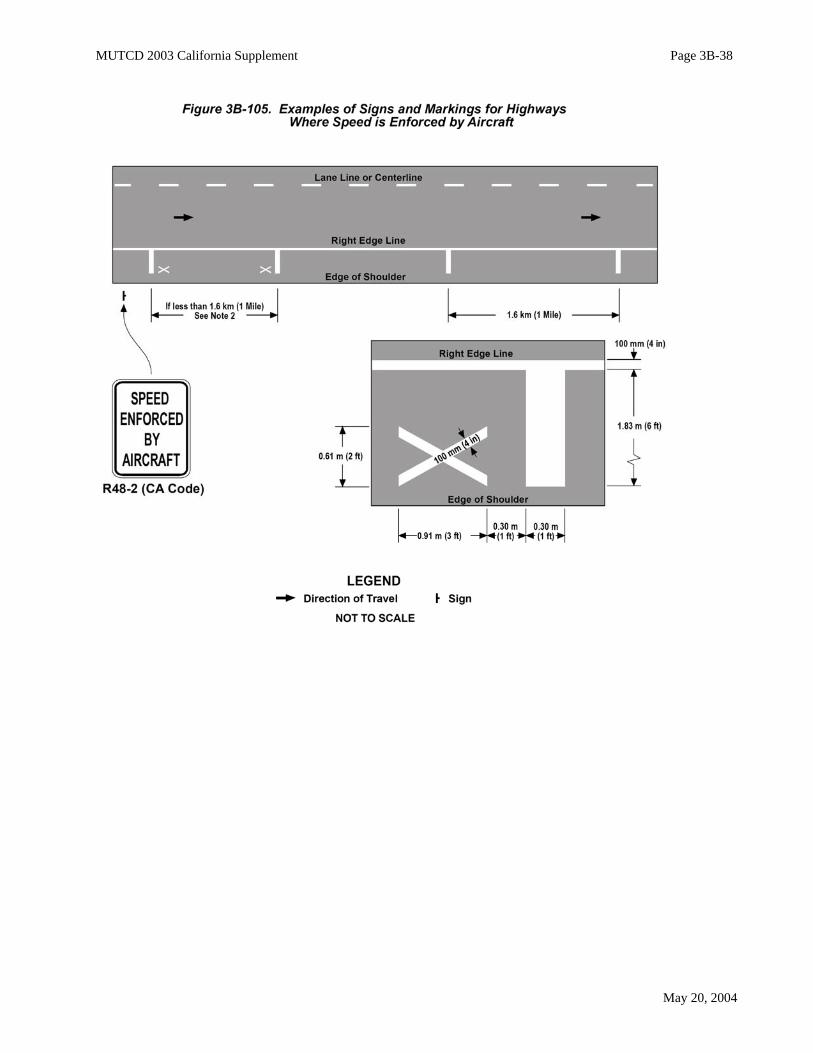
Section 3B.20 Speed Measurement MarkingsThe following is added to this section:Support:
The California Highway Patrol patrols certain highways with both helicopters and fixed-wing aircraft.The purpose of the patrol is to monitor traffic, provide motorist assistance and initiate appropriateenforcement action.
In order to make the air patrol effective, the California Highway Patrol and Caltrans have agreed uponmarkings and signs as shown in Figure 3B-105.Option:
Speed measurement markings may be placed on the right shoulder in areas patrolled by aircraft asrequested by the California Highway Patrol.Standard:
Where there is an equation of more than 30 m (100 ft) in a 1.6 km (1 mi) posting, a white 'X'pavement marking shall be placed at each end of the section to indicate the markings are less than 1.6km (1 mi) apart.Guidance:
The SPEED ENFORCED BY AIRCRAFT (CA Code R48-2) sign should be used for both directions oftravel and should be spaced at 40 km (25 mi) intervals.
Pavement marking should be placed on the shoulder in one direction only, except where the opposingroadway is widely separated.Option:
In areas where identifying features are widely separated, white 0.91 m (3 ft) high post kilometer (mile)numbers may be placed at 8 km (5 mi) points where needed for aircraft reference.Standard:
Markings shall not be on the traveled way. Option:
If routes with narrow shoulders are requested for marking, the standard marking shape may be modifiedto provide an equivalent area without encroaching on the traveled way or the Alternate Marking Systemdescribed.Support:
The Alternate Marking System is a 200 mm (8 in) wide solid white longitudinal line, 6.1 m (20 ft) inlength and in line with the right edge line. It is preceded and followed by a 6.1 m (20 ft) gap in the rightedge line.
Section 3B.21 Curb MarkingsStandard:
Paragraphs 6 (“Retroreflective solid yellow…”) and 7 (“Retroreflective solid white…”) are deleted.In California, object markers are used for this purpose. See Chapter 3C.The following is added to this section:Support:
Refer to Section 2B.39 for Parking Regulations.In California, curb markings are not used for delineating traffic. They are mainly used for parking
regulations.
MUTCD 2003 California Supplement Page 3B-38
May 20, 2004

MUTCD 2003 California Supplement Page 3B-39
May 20, 2004
Standard:The color of curb markings shall conform to CVC 21458 quoted below:(a) Whenever local authorities enact local parking regulations and indicate them by the use of
paint upon curbs, the following colors only shall be used, and the colors indicate as follows:(1) Red indicates no stopping, standing, or parking, whether the vehicle is attended or
unattended, except that a bus may stop in a red zone marked or sign posted as a busloading zone.
(2) Yellow indicates stopping only for the purpose of loading or unloading passengers orfreight for the time as may be specified by local ordinance.
(3) White indicates stopping for either of the following purposes:(A) Loading or unloading of passengers for the time as may be specified by local ordinance.(B) Depositing mail in an adjacent mailbox.
(4) Green indicates time limit parking specified by local ordinance.(5) Blue indicates parking limited exclusively to the vehicles of disabled persons and disabled
veterans.(b) Regulations adopted pursuant to subdivision (a) shall be effective on days and during hours or
times as prescribed by local ordinances.Parking regulations shall be covered by ordinance or order of the authority having jurisdiction
over the street or highway.Option:
Curb markings may supplement standard signs.Prohibitions or restrictions enacted by local authorities under Sections 22506 or 22507 may be indicated
by marking curbs as prescribed by CVC Section 21458.Policy on Parking RestrictionsSupport:
Loading Zones - Local authorities are authorized by Section 21112 of the CVC to license and regulatethe location of stands on streets and highways for use of taxicabs and other public carriers for hire. Wheresuch stands are located on State highways, and highway maintenance is not delegated to the local authority,the approval of the Department is required. The District Directors have been delegated authority to approvelocal ordinances establishing such stands.
Loading zone ordinances restricted for certain segments of traffic such as "hotel patrons only" will not beapproved. Bus stand ordinances are generally approved. Standard:
Whenever practicable, bus stands shall be located on the far side of the intersection.
Section 3B.22 Preferential Lane Word and Symbol MarkingsSupport:
In Paragraph 9 (“The spacing of…”) the second sentence (“Markings spaced as…”) is deleted andreplaced with the following:
Markings spaced as close as 24 m (80 ft) apart might be appropriate on city streets, while markingsspaced 150 m (500 ft) might be appropriate for freeways (Refer to HOV Guidelines) and 56 m (180 ft) foronramps (Refer to Ramp Meter Design Manual). See Section 1A.11 for information regarding thesepublications.Standard:
Paragraph 10 (“The vehicle occupancy…”) is deleted and shall not be applicable in California.The following is added to this section:Support:
For State highways, see Department of Transportation’s High Occupancy Vehicle (HOV) Guidelines andRamp Meter Design Manual. See Section 1A.11 for information regarding these publications.
MUTCD 2003 California Supplement Page 3B-40
May 20, 2004
_______________________________________________________________________________________
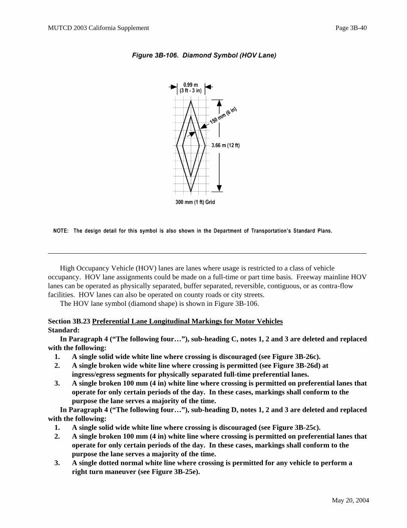
High Occupancy Vehicle (HOV) lanes are lanes where usage is restricted to a class of vehicleoccupancy. HOV lane assignments could be made on a full-time or part time basis. Freeway mainline HOVlanes can be operated as physically separated, buffer separated, reversible, contiguous, or as contra-flowfacilities. HOV lanes can also be operated on county roads or city streets.
The HOV lane symbol (diamond shape) is shown in Figure 3B-106.
Section 3B.23 Preferential Lane Longitudinal Markings for Motor VehiclesStandard:
In Paragraph 4 (“The following four…”), sub-heading C, notes 1, 2 and 3 are deleted and replacedwith the following:
1. A single solid wide white line where crossing is discouraged (see Figure 3B-26c). 2. A single broken wide white line where crossing is permitted (see Figure 3B-26d) at
ingress/egress segments for physically separated full-time preferential lanes. 3. A single broken 100 mm (4 in) white line where crossing is permitted on preferential lanes that
operate for only certain periods of the day. In these cases, markings shall conform to thepurpose the lane serves a majority of the time.
In Paragraph 4 (“The following four…”), sub-heading D, notes 1, 2 and 3 are deleted and replacedwith the following:
1. A single solid wide white line where crossing is discouraged (see Figure 3B-25c). 2. A single broken 100 mm (4 in) white line where crossing is permitted on preferential lanes that
operate for only certain periods of the day. In these cases, markings shall conform to thepurpose the lane serves a majority of the time.
3. A single dotted normal white line where crossing is permitted for any vehicle to perform aright turn maneuver (see Figure 3B-25e).

MUTCD 2003 California Supplement Page 3B-41
May 20, 2004
Option:Paragraph 6 (“When concurrent flow…”) is deleted and replaced with the following:When concurrent flow preferential lanes and other travel lanes are separated by 3.6 m (12 ft) or more,
chevron markings may be placed in the neutral area.Guidance:
If used, the chevron spacing should be 60 m (200 ft) or greater.Standard:
Paragraph 7 (“For full-time…”) is deleted and shall not be applicable in California.The following is added to this section:Support:
The striping pattern for the lane lines between the HOV lane and the adjacent normal flow lanes willvary depending on the condition. See Department of Transportation’s High Occupancy Vehicle (HOV)Guidelines and Ramp Meter Design Manual for the appropriate HOV lane line striping patterns andmarkings. See Section 1A.11 for information regarding these publications.
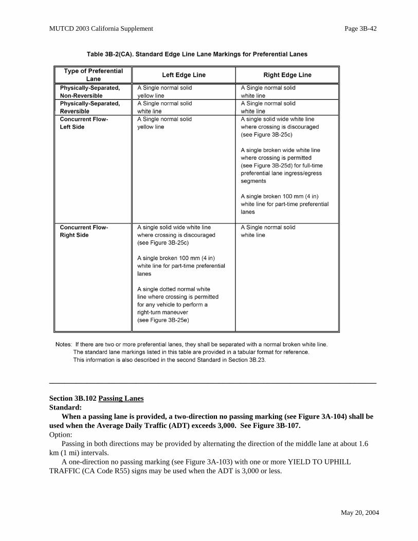
Table 3B-2. Standard Edge Line Lane Markings for Preferential LanesStandard:
MUTCD Table 3B-2 is deleted and replaced with Table 3B-2 (CA).
Section 3B.26 Speed Hump MarkingsThe following is added to this section:Support:
Per CVC 440, speed humps or bumps are not official traffic control devices.
Section 3B.101 Diagonal and Chevron MarkingsGuidance:
Diagonal and chevron markings should be used, when in the opinion of an engineer, it is necessary toadd emphasis or to discourage vehicular travel upon a paint formed roadway feature such as an unusuallywide shoulder area, a pedestrian refuge island, or a traffic divisional or channelization island.
Diagonal lines, when used, should be installed between an edge line and traffic island, or between pairsof double yellow lines.
Chevron markings, when used, should be installed between channelizing lines for traffic flows in thesame direction. Support:
The applicable channelizing lines for chevron markings are shown in Figure 3A-110, Details 36, 36Aand 36B and pairs of lines shown in Figure 3A-112, Details 38 and 38A.
The diagonal lines or chevron markings are normally 300 mm (12 in) wide.Standard:
Diagonal lines and chevrons shall be the same color as the line or lines to which they connect andshall point at a 45-degree forward angle.
Diagonal lines or chevrons, if used, shall be the same color as the edge line.Option:
The spacing between these lines may vary from 0.3 m (1 ft) in a pedestrian crosswalk to 60 m (200 ft) forvehicular traffic.
MUTCD 2003 California Supplement Page 3B-42
May 20, 2004
_______________________________________________________________________________________
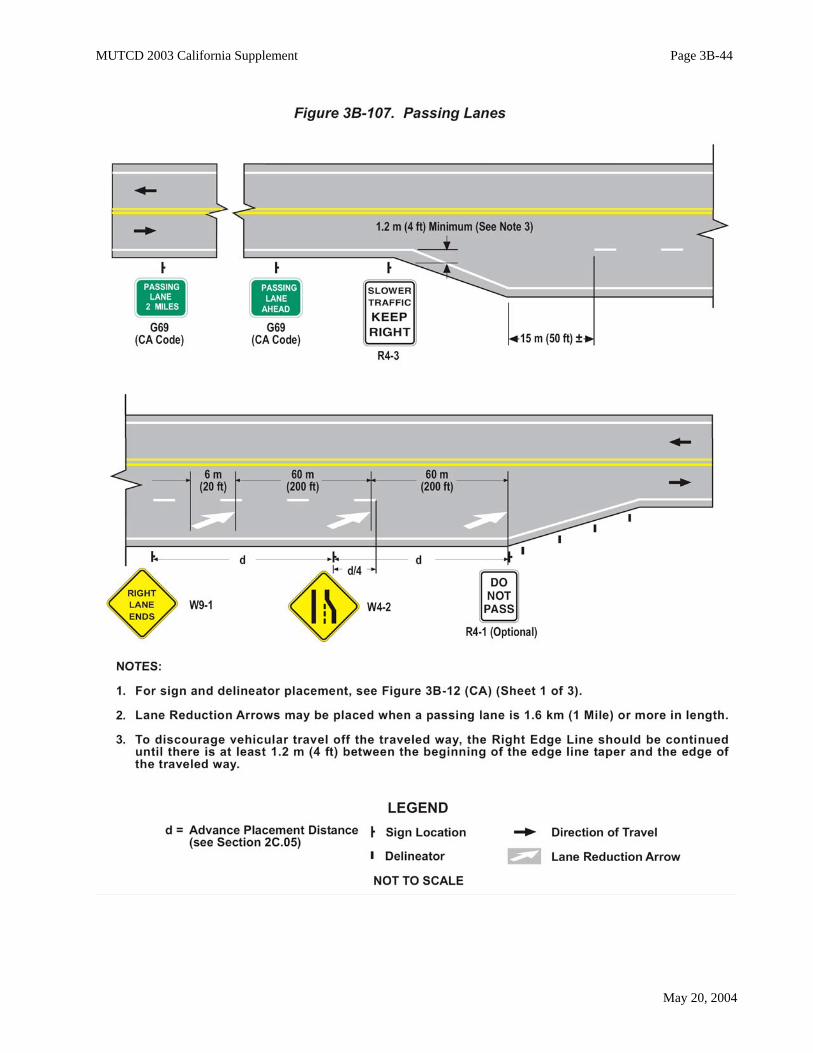
Section 3B.102 Passing LanesStandard:
When a passing lane is provided, a two-direction no passing marking (see Figure 3A-104) shall beused when the Average Daily Traffic (ADT) exceeds 3,000. See Figure 3B-107. Option:
Passing in both directions may be provided by alternating the direction of the middle lane at about 1.6km (1 mi) intervals.
A one-direction no passing marking (see Figure 3A-103) with one or more YIELD TO UPHILLTRAFFIC (CA Code R55) signs may be used when the ADT is 3,000 or less.

MUTCD 2003 California Supplement Page 3B-43
May 20, 2004
Section 3B.103 Truck LanesStandard:
When a climbing lane is provided on an upgrade and it is necessary to prohibit trucks frompassing slower moving vehicles, a 200 mm (8 in) solid white line shall be used in place of the standardlane line stripe.
The TRUCKS RIGHT LANE ONLY (CA Code R53B) sign shall be placed at the beginning of therestriction and at approximately 0.4 km (1/4 mi) intervals. When the restriction is necessary onlyduring certain hours, the Specific Hours/Days Plaque (CA Code R82A) shall be placed below the R53B(CA Code) sign.
A TRUCK LANE (R4-6) sign shall be placed in advance of the truck lane. An END TRUCKLANE (CA Code R53A) sign shall be placed at the end of the restriction. See Figure 3B-12 (CA) forsigning and marking the end of an extra lane.
Section 3B.104 Turn LanesSupport:
Refer to CVC 21460.5 for Two-Way Left-Turn Lanes.For details of two-way left-turn lanes, see Figure 3B-7 (CA). For left turn channelization, see Figure 3B-
101 and Department of Transportation’s Highway Design Manual, Section 405.2. See Section 1A.11 forinformation regarding this publication.Standard:
Left-turn or right-turn lanes shall be separated from the through lanes by a single solid 200 mm (8in) wide white line as shown in Figure 3A-112.
Section 3B.105 TurnoutsGuidance:
Paved turnouts should be marked with a 200 mm (8 in) wide single solid white line between the throughlane and the turnout. The line should not extend through the entry and exit areas. See Figure 3B-108 andDepartment of Transportation’s Highway Design Manual, Section 204.5 (4). See Section 1A.11 forinformation regarding this publication.
Turnouts should be 60 m (200 ft) to 150 m (500 ft) in length including a short taper of 15 m (50 ft) ateach end. Turnouts should not be longer than 150 m (500 ft).
The right edge line should be dropped throughout the length of the turnout.Option:
Turnout length may be increased 30 m (100 ft) on down grades over 3%.
Section 3B.106 Rumble StripsSupport:
Rumble strips are bands of raised material or indentations formed or ground into the traveled way, on thecenterline or shoulders. Rumble strips call the motorist's attention to standard warning or regulatory devicesor otherwise alert drivers by transmitting sound and/or vibration through the vehicle.Option:
Rumble strips may be used in the traveled way on California's streets and highways if the traffic engineerconsiders their use as the optimal solution to the identified problem.Guidance:
The use of rumble strips on State highways should be reviewed by the Department of Transportation’sDistrict Traffic Engineer or their representative. Option:
Rumble strips may be incorporated into rehabilitation projects to replace existing rumble strips withoutan extensive review.
MUTCD 2003 California Supplement Page 3B-44
May 20, 2004

MUTCD 2003 California Supplement Page 3B-45
May 20, 2004
_______________________________________________________________________________________
Guidance:Requests should include a description of location, reasons for use, the alternatives which were
considered, collision history and a discussion of standard traffic control devices which have been or are inplace.Traveled Way Rumble Strips:Support:
Rumble strips on the traveled way are 19 mm (0.75 in) or less in height if raised or 25 mm (1 in) or lessin depth if rolled-in indentations, 8.5 mm (0.33 in) +/- 1.5 mm (0.06 in) if ground-in indentations andgenerally extend across the travel lanes.
A ground in rumble strip with the dimensions shown above has been field reviewed to confirmrideability for bicyclists & motorcyclists.
There are several significant disadvantages to the use of rumble strips across the travel lanes. Theseinclude:
• An abrupt rise in the roadway can present problems to bicyclists and motorcyclists. For this reason,there should be provisions made for cyclists to safely traverse through or around raised rumble strips.
• Nearby residents may be subjected to noise.Typical locations where rumble strips on the traveled way have been used include:• End of a freeway.• In advance of toll booths.• Within a construction zone in advance of the workers.• In advance of a "T" Intersection where the motorist is not expecting to stop.

MUTCD 2003 California Supplement Page 3B-46
May 20, 2004
Shoulder Rumble Strips:Support:
Shoulder rumble strips are 19 mm (0.75 in) or less in height if raised 25 mm (1 in) in depth for rolled-inindentations and 8.5 mm (0.33 in) +/- 1.5 mm (0.06 in) for ground-in indentations that extend along thehighway shoulder. The maximum width of shoulder rumble strips is 300 mm (12 in) for both rolled-in andground-in indentations.Guidance:
Where bicycles are permitted, shoulder rumble strips should not be used unless approximately 1.5 m (5ft) of clear shoulder width for bicycle use is available between the rumble strips and the outer edge of theshoulder. Standard:
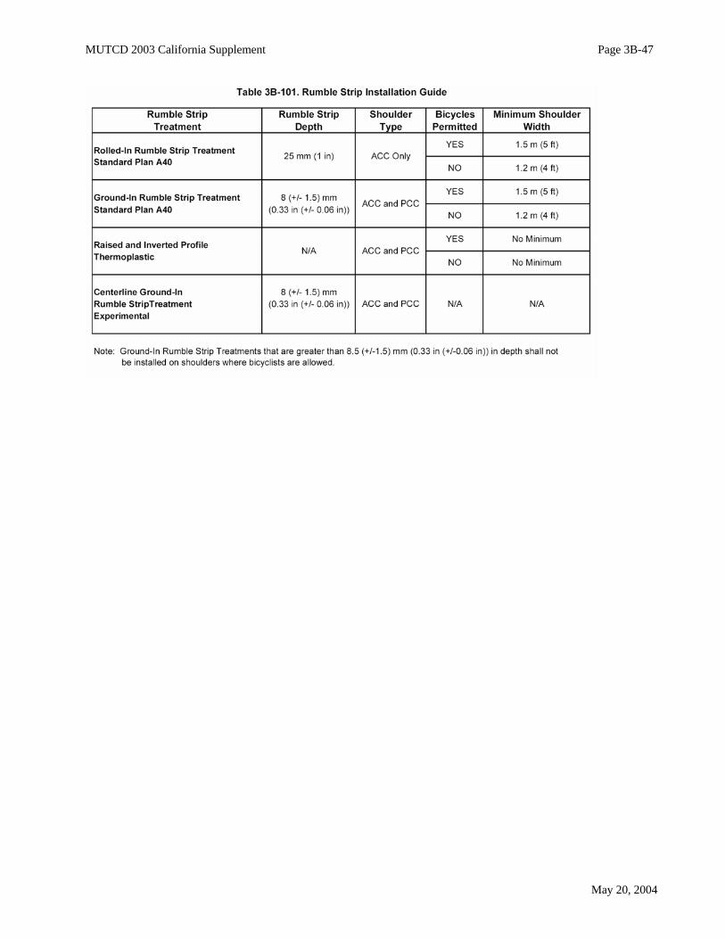
If shoulder width is less than 1.5 m (5 ft) and rumble strips are required, then only raised andinverted profile thermoplastic stripe shall be used. Ground-in rumble strip treatments that aregreater than 8.5 mm (0.33 in) +/- 1.5 mm (0.06 in) depth shall not be installed on shoulders wherebicyclists are allowed.Option:
Research findings indicate that the use of rumble strips on shoulders of freeways in remote areas mayreduce drift-off-road accidents. Drifting off the road is most likely to be a problem on freeways with fewinterchanges and long tangents. Rumble strips may be used on other roadway types as well to address driftoff roadway collisions at locations where they are a concern. The rumble strips may consist of groovesrolled into the hot mix as part of a resurfacing project, ground-in indentation in Portland Concrete Cement orAsphalt Concrete in existing roadway shoulders, or the application of a raised and inverted profilethermoplastic. Guidance:
When roadways in remote areas are to be resurfaced, consideration should be given to the drift-off-roadproblem and the use of rumble strips considered.Option:
Table 3B-101 may be used by the District Traffic Engineer as a guide to determine the appropriaterumble strip treatment for various shoulder types.Centerline Rumble Strips:Support:
Centerline rumble strips are currently being used experimentally at 2 and 3 lane locations in Californiaand across the nation as a tool to address drift across the centerline collisions. Option:
The District Traffic Engineer may consider the use of centerline rumble strips with other considerationsas a means of addressing drift across the centerline collisions.
MUTCD 2003 California Supplement Page 3B-47
May 20, 2004