chapter 3 viewing - coerujchai/comgraphics/redbook/redbook-03.pdf · chapter 3 viewing chapter...
TRANSCRIPT

OpenGL Programming Guide (Addison-WesleyPublishing Company)
Chapter 3ViewingChapter Objectives
After reading this chapter, you’ll be able to do the following:
View a geometric model in any orientation by transforming it in three-dimensional space
Control the location in three-dimensional space from which the model is viewed
Clip undesired portions of the model out of the scene that’s to be viewed
Manipulate the appropriate matrix stacks that control model transformation for viewing andproject the model onto the screen
Combine multiple transformations to mimic sophisticated systems in motion, such as a solarsystem or an articulated robot arm
Reverse or mimic the operations of the geometric processing pipeline
Chapter 2 explained how to instruct OpenGL to draw the geometric models you want displayed in yourscene. Now you must decide how you want to position the models in the scene, and you must choose avantage point from which to view the scene. You can use the default positioning and vantage point, butmost likely you want to specify them.
Look at the image on the cover of this book. The program that produced that image contained a singlegeometric description of a building block. Each block was carefully positioned in the scene: Someblocks were scattered on the floor, some were stacked on top of each other on the table, and some wereassembled to make the globe. Also, a particular viewpoint had to be chosen. Obviously, we wanted tolook at the corner of the room containing the globe. But how far away from the scene - and whereexactly - should the viewer be? We wanted to make sure that the final image of the scene contained agood view out the window, that a portion of the floor was visible, and that all the objects in the scenewere not only visible but presented in an interesting arrangement. This chapter explains how to useOpenGL to accomplish these tasks: how to position and orient models in three-dimensional space andhow to establish the location - also in three-dimensional space - of the viewpoint. All of these factorshelp determine exactly what image appears on the screen.
You want to remember that the point of computer graphics is to create a two-dimensional image ofthree-dimensional objects (it has to be two-dimensional because it’s drawn on a flat screen), but youneed to think in three-dimensional coordinates while making many of the decisions that determine what

gets drawn on the screen. A common mistake people make when creating three-dimensional graphics isto start thinking too soon that the final image appears on a flat, two-dimensional screen. Avoid thinkingabout which pixels need to be drawn, and instead try to visualize three-dimensional space. Create yourmodels in some three-dimensional universe that lies deep inside your computer, and let the computer doits job of calculating which pixels to color.
A series of three computer operations convert an object’s three-dimensional coordinates to pixelpositions on the screen.
Transformations, which are represented by matrix multiplication, include modeling, viewing, andprojection operations. Such operations include rotation, translation, scaling, reflecting,orthographic projection, and perspective projection. Generally, you use a combination of severaltransformations to draw a scene.
Since the scene is rendered on a rectangular window, objects (or parts of objects) that lie outsidethe window must be clipped. In three-dimensional computer graphics, clipping occurs by throwingout objects on one side of a clipping plane.
Finally, a correspondence must be established between the transformed coordinates and screenpixels. This is known as a viewport transformation.
This chapter describes all of these operations, and how to control them, in the following major sections:
"Overview: The Camera Analogy" gives an overview of the transformation process by describingthe analogy of taking a photograph with a camera, presents a simple example program thattransforms an object, and briefly describes the basic OpenGL transformation commands.
"Viewing and Modeling Transformations" explains in detail how to specify and to imagine theeffect of viewing and modeling transformations. These transformations orient the model and thecamera relative to each other to obtain the desired final image.
"Projection Transformations" describes how to specify the shape and orientation of the viewingvolume. The viewing volume determines how a scene is projected onto the screen (with aperspective or orthographic projection) and which objects or parts of objects are clipped out of thescene.
"Viewport Transformation" explains how to control the conversion of three-dimensional modelcoordinates to screen coordinates.
"Troubleshooting Transformations" presents some tips for discovering why you might not begetting the desired effect from your modeling, viewing, projection, and viewport transformations.
"Manipulating the Matrix Stacks" discusses how to save and restore certain transformations. Thisis particularly useful when you’re drawing complicated objects that are built up from simpler ones.
"Additional Clipping Planes" describes how to specify additional clipping planes beyond thosedefined by the viewing volume.
"Examples of Composing Several Transformations" walks you through a couple of morecomplicated uses for transformations.
"Reversing or Mimicking Transformations" shows you how to take a transformed point in windowcoordinates and reverse the transformation to obtain its original object coordinates. Thetransformation itself (without reversal) can also be emulated.
Overview: The Camera Analogy
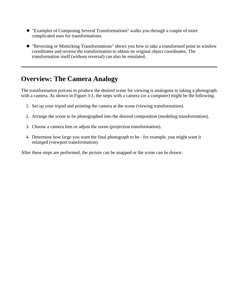
The transformation process to produce the desired scene for viewing is analogous to taking a photographwith a camera. As shown in Figure 3-1, the steps with a camera (or a computer) might be the following.
1. Set up your tripod and pointing the camera at the scene (viewing transformation).
2. Arrange the scene to be photographed into the desired composition (modeling transformation).
3. Choose a camera lens or adjust the zoom (projection transformation).
4. Determine how large you want the final photograph to be - for example, you might want itenlarged (viewport transformation).
After these steps are performed, the picture can be snapped or the scene can be drawn.

Figure 3-1 : The Camera Analogy
Note that these steps correspond to the order in which you specify the desired transformations in yourprogram, not necessarily the order in which the relevant mathematical operations are performed on anobject’s vertices. The viewing transformations must precede the modeling transformations in your code,but you can specify the projection and viewport transformations at any point before drawing occurs.Figure 3-2 shows the order in which these operations occur on your computer.
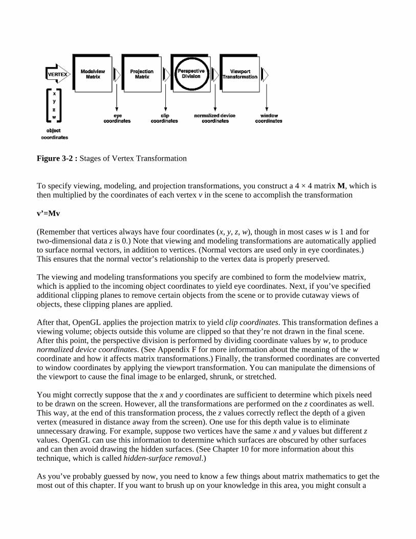
Figure 3-2 : Stages of Vertex Transformation
To specify viewing, modeling, and projection transformations, you construct a 4 × 4 matrix M, which isthen multiplied by the coordinates of each vertex v in the scene to accomplish the transformation
v’=Mv
(Remember that vertices always have four coordinates (x, y, z, w), though in most cases w is 1 and fortwo-dimensional data z is 0.) Note that viewing and modeling transformations are automatically appliedto surface normal vectors, in addition to vertices. (Normal vectors are used only in eye coordinates.)This ensures that the normal vector’s relationship to the vertex data is properly preserved.
The viewing and modeling transformations you specify are combined to form the modelview matrix,which is applied to the incoming object coordinates to yield eye coordinates. Next, if you’ve specifiedadditional clipping planes to remove certain objects from the scene or to provide cutaway views ofobjects, these clipping planes are applied.
After that, OpenGL applies the projection matrix to yield clip coordinates. This transformation defines aviewing volume; objects outside this volume are clipped so that they’re not drawn in the final scene.After this point, the perspective division is performed by dividing coordinate values by w, to producenormalized device coordinates. (See Appendix F for more information about the meaning of the wcoordinate and how it affects matrix transformations.) Finally, the transformed coordinates are convertedto window coordinates by applying the viewport transformation. You can manipulate the dimensions ofthe viewport to cause the final image to be enlarged, shrunk, or stretched.
You might correctly suppose that the x and y coordinates are sufficient to determine which pixels needto be drawn on the screen. However, all the transformations are performed on the z coordinates as well.This way, at the end of this transformation process, the z values correctly reflect the depth of a givenvertex (measured in distance away from the screen). One use for this depth value is to eliminateunnecessary drawing. For example, suppose two vertices have the same x and y values but different zvalues. OpenGL can use this information to determine which surfaces are obscured by other surfacesand can then avoid drawing the hidden surfaces. (See Chapter 10 for more information about thistechnique, which is called hidden-surface removal.)
As you’ve probably guessed by now, you need to know a few things about matrix mathematics to get themost out of this chapter. If you want to brush up on your knowledge in this area, you might consult a

textbook on linear algebra.
A Simple Example: Drawing a Cube
Example 3-1 draws a cube that’s scaled by a modeling transformation (see Figure 3-3). The viewingtransformation, gluLookAt(), positions and aims the camera towards where the cube is drawn. Aprojection transformation and a viewport transformation are also specified. The rest of this section walksyou through Example 3-1 and briefly explains the transformation commands it uses. The succeedingsections contain the complete, detailed discussion of all OpenGL’s transformation commands.
Figure 3-3 : Transformed Cube
Example 3-1 : Transformed Cube: cube.c
#include <GL/gl.h>#include <GL/glu.h>#include <GL/glut.h>
void init(void) { glClearColor (0.0, 0.0, 0.0, 0.0); glShadeModel (GL_FLAT);}
void display(void){ glClear (GL_COLOR_BUFFER_BIT); glColor3f (1.0, 1.0, 1.0); glLoadIdentity (); /* clear the matrix */ /* viewing transformation */ gluLookAt (0.0, 0.0, 5.0, 0.0, 0.0, 0.0, 0.0, 1.0, 0.0); glScalef (1.0, 2.0, 1.0); /* modeling transformation */ glutWireCube (1.0); glFlush ();}
void reshape (int w, int h){ glViewport (0, 0, (GLsizei) w, (GLsizei) h); glMatrixMode (GL_PROJECTION); glLoadIdentity (); glFrustum (-1.0, 1.0, -1.0, 1.0, 1.5, 20.0); glMatrixMode (GL_MODELVIEW);}
int main(int argc, char** argv){ glutInit(&argc, argv);

glutInitDisplayMode (GLUT_SINGLE | GLUT_RGB); glutInitWindowSize (500, 500); glutInitWindowPosition (100, 100); glutCreateWindow (argv[0]); init (); glutDisplayFunc(display); glutReshapeFunc(reshape); glutMainLoop(); return 0;}
The Viewing Transformation
Recall that the viewing transformation is analogous to positioning and aiming a camera. In this codeexample, before the viewing transformation can be specified, the current matrix is set to the identitymatrix with glLoadIdentity(). This step is necessary since most of the transformation commandsmultiply the current matrix by the specified matrix and then set the result to be the current matrix. If youdon’t clear the current matrix by loading it with the identity matrix, you continue to combine previoustransformation matrices with the new one you supply. In some cases, you do want to perform suchcombinations, but you also need to clear the matrix sometimes.
In Example 3-1, after the matrix is initialized, the viewing transformation is specified with gluLookAt().The arguments for this command indicate where the camera (or eye position) is placed, where it isaimed, and which way is up. The arguments used here place the camera at (0, 0, 5), aim the camera lenstowards (0, 0, 0), and specify the up-vector as (0, 1, 0). The up-vector defines a unique orientation forthe camera.
If gluLookAt() was not called, the camera has a default position and orientation. By default, the camerais situated at the origin, points down the negative z-axis, and has an up-vector of (0, 1, 0). So in Example3-1, the overall effect is that gluLookAt() moves the camera 5 units along the z-axis. (See "Viewing andModeling Transformations" for more information about viewing transformations.)
The Modeling Transformation
You use the modeling transformation to position and orient the model. For example, you can rotate,translate, or scale the model - or perform some combination of these operations. In Example 3-1,glScalef() is the modeling transformation that is used. The arguments for this command specify howscaling should occur along the three axes. If all the arguments are 1.0, this command has no effect. InExample 3-1, the cube is drawn twice as large in the y direction. Thus, if one corner of the cube hadoriginally been at (3.0, 3.0, 3.0), that corner would wind up being drawn at (3.0, 6.0, 3.0). The effect ofthis modeling transformation is to transform the cube so that it isn’t a cube but a rectangular box.
Try This
Change the gluLookAt() call in Example 3-1 to the modeling transformation glTranslatef() withparameters (0.0, 0.0, -5.0). The result should look exactly the same as when you used gluLookAt().Why are the effects of these two commands similar?
Note that instead of moving the camera (with a viewing transformation) so that the cube could beviewed, you could have moved the cube away from the camera (with a modeling transformation). This
duality in the nature of viewing and modeling transformations is why you need to think about the effectof both types of transformations simultaneously. It doesn’t make sense to try to separate the effects, butsometimes it’s easier to think about them one way rather than the other. This is also why modeling andviewing transformations are combined into the modelview matrix before the transformations are applied.(See "Viewing and Modeling Transformations" for more detail on how to think about modeling andviewing transformations and how to specify them to get the result you want.)
Also note that the modeling and viewing transformations are included in the display() routine, alongwith the call that’s used to draw the cube, glutWireCube(). This way, display() can be used repeatedlyto draw the contents of the window if, for example, the window is moved or uncovered, and you’veensured that each time, the cube is drawn in the desired way, with the appropriate transformations. Thepotential repeated use of display() underscores the need to load the identity matrix before performingthe viewing and modeling transformations, especially when other transformations might be performedbetween calls to display().
The Projection Transformation
Specifying the projection transformation is like choosing a lens for a camera. You can think of thistransformation as determining what the field of view or viewing volume is and therefore what objectsare inside it and to some extent how they look. This is equivalent to choosing among wide-angle,normal, and telephoto lenses, for example. With a wide-angle lens, you can include a wider scene in thefinal photograph than with a telephoto lens, but a telephoto lens allows you to photograph objects asthough they’re closer to you than they actually are. In computer graphics, you don’t have to pay $10,000for a 2000-millimeter telephoto lens; once you’ve bought your graphics workstation, all you need to dois use a smaller number for your field of view.
In addition to the field-of-view considerations, the projection transformation determines how objects areprojected onto the screen, as its name suggests. Two basic types of projections are provided for you byOpenGL, along with several corresponding commands for describing the relevant parameters indifferent ways. One type is the perspective projection, which matches how you see things in daily life.Perspective makes objects that are farther away appear smaller; for example, it makes railroad tracksappear to converge in the distance. If you’re trying to make realistic pictures, you’ll want to chooseperspective projection, which is specified with the glFrustum() command in this code example.
The other type of projection is orthographic, which maps objects directly onto the screen withoutaffecting their relative size. Orthographic projection is used in architectural and computer-aided designapplications where the final image needs to reflect the measurements of objects rather than how theymight look. Architects create perspective drawings to show how particular buildings or interior spaceslook when viewed from various vantage points; the need for orthographic projection arises whenblueprint plans or elevations are generated, which are used in the construction of buildings. (See"Projection Transformations" for a discussion of ways to specify both kinds of projectiontransformations.)
Before glFrustum() can be called to set the projection transformation, some preparation needs tohappen. As shown in the reshape() routine in Example 3-1, the command called glMatrixMode() isused first, with the argument GL_PROJECTION. This indicates that the current matrix specifies theprojection transformation; the following transformation calls then affect the projection matrix. As youcan see, a few lines later glMatrixMode() is called again, this time with GL_MODELVIEW as the

argument. This indicates that succeeding transformations now affect the modelview matrix instead of theprojection matrix. (See "Manipulating the Matrix Stacks" for more information about how to control theprojection and modelview matrices.)
Note that glLoadIdentity() is used to initialize the current projection matrix so that only the specifiedprojection transformation has an effect. Now glFrustum() can be called, with arguments that define theparameters of the projection transformation. In this example, both the projection transformation and theviewport transformation are contained in the reshape() routine, which is called when the window is firstcreated and whenever the window is moved or reshaped. This makes sense, since both projecting (thewidth to height aspect ratio of the projection viewing volume) and applying the viewport relate directlyto the screen, and specifically to the size or aspect ratio of the window on the screen.
Try This
Change the glFrustum() call in Example 3-1 to the more commonly used Utility Library routinegluPerspective() with parameters (60.0, 1.0, 1.5, 20.0). Then experiment with different values,especially for fovy and aspect.
The Viewport Transformation
Together, the projection transformation and the viewport transformation determine how a scene getsmapped onto the computer screen. The projection transformation specifies the mechanics of how themapping should occur, and the viewport indicates the shape of the available screen area into which thescene is mapped. Since the viewport specifies the region the image occupies on the computer screen,you can think of the viewport transformation as defining the size and location of the final processedphotograph - for example, whether the photograph should be enlarged or shrunk.
The arguments to glViewport() describe the origin of the available screen space within the window - (0,0) in this example - and the width and height of the available screen area, all measured in pixels on thescreen. This is why this command needs to be called within reshape() - if the window changes size, theviewport needs to change accordingly. Note that the width and height are specified using the actualwidth and height of the window; often, you want to specify the viewport this way rather than giving anabsolute size. (See "Viewport Transformation" for more information about how to define the viewport.)
Drawing the Scene
Once all the necessary transformations have been specified, you can draw the scene (that is, take thephotograph). As the scene is drawn, OpenGL transforms each vertex of every object in the scene by themodeling and viewing transformations. Each vertex is then transformed as specified by the projectiontransformation and clipped if it lies outside the viewing volume described by the projectiontransformation. Finally, the remaining transformed vertices are divided by w and mapped onto theviewport.
General-Purpose Transformation Commands
This section discusses some OpenGL commands that you might find useful as you specify desiredtransformations. You’ve already seen a couple of these commands, glMatrixMode() andglLoadIdentity(). The other two commands described here - glLoadMatrix*() and glMultMatrix*() -

allow you to specify any transformation matrix directly and then to multiply the current matrix by thatspecified matrix. More specific transformation commands - such as gluLookAt() and glScale*() - aredescribed in later sections.
As described in the preceding section, you need to state whether you want to modify the modelview orprojection matrix before supplying a transformation command. You choose the matrix withglMatrixMode(). When you use nested sets of OpenGL commands that might be called repeatedly,remember to reset the matrix mode correctly. (The glMatrixMode() command can also be used toindicate the texture matrix; texturing is discussed in detail in "The Texture Matrix Stack" in Chapter 9.)
void glMatrixMode(GLenum mode);Specifies whether the modelview, projection, or texture matrix will be modified, using theargument GL_MODELVIEW, GL_PROJECTION, or GL_TEXTURE for mode. Subsequenttransformation commands affect the specified matrix. Note that only one matrix can be modified ata time. By default, the modelview matrix is the one that’s modifiable, and all three matricescontain the identity matrix.
You use the glLoadIdentity() command to clear the currently modifiable matrix for futuretransformation commands, since these commands modify the current matrix. Typically, you always callthis command before specifying projection or viewing transformations, but you might also call it beforespecifying a modeling transformation.
void glLoadIdentity(void); Sets the currently modifiable matrix to the 4 × 4 identity matrix.
If you want to specify explicitly a particular matrix to be loaded as the current matrix, useglLoadMatrix*(). Similarly, use glMultMatrix*() to multiply the current matrix by the matrix passedin as an argument. The argument for both these commands is a vector of sixteen values (m1, m2, ... ,m16) that specifies a matrix M as follows:
Remember that you might be able to maximize efficiency by using display lists to store frequently usedmatrices (and their inverses) rather than recomputing them. (See "Display-List Design Philosophy" inChapter 7.) (OpenGL implementations often must compute the inverse of the modelview matrix so thatnormals and clipping planes can be correctly transformed to eye coordinates.)
Caution: If you’re programming in C and you declare a matrix as m[4][4], then the element m[i][j] is inthe ith column and jth row of the OpenGL transformation matrix. This is the reverse of the standard Cconvention in which m[i][j] is in row i and column j. To avoid confusion, you should declare yourmatrices as m[16].
void glLoadMatrix{fd}(const TYPE *m);Sets the sixteen values of the current matrix to those specified by m.

void glMultMatrix{fd}(const TYPE *m);Multiplies the matrix specified by the sixteen values pointed to by m by the current matrix andstores the result as the current matrix.
Note: All matrix multiplication with OpenGL occurs as follows: Suppose the current matrix is C and thematrix specified with glMultMatrix*() or any of the transformation commands is M. Aftermultiplication, the final matrix is always CM. Since matrix multiplication isn’t generally commutative,the order makes a difference.
Viewing and Modeling Transformations
Viewing and modeling transformations are inextricably related in OpenGL and are in fact combined intoa single modelview matrix. (See "A Simple Example: Drawing a Cube.") One of the toughest problemsnewcomers to computer graphics face is understanding the effects of combined three-dimensionaltransformations. As you’ve already seen, there are alternative ways to think about transformations - doyou want to move the camera in one direction, or move the object in the opposite direction? Each way ofthinking about transformations has advantages and disadvantages, but in some cases one way morenaturally matches the effect of the intended transformation. If you can find a natural approach for yourparticular application, it’s easier to visualize the necessary transformations and then write thecorresponding code to specify the matrix manipulations. The first part of this section discusses how tothink about transformations; later, specific commands are presented. For now, we use only thematrix-manipulation commands you’ve already seen. Finally, keep in mind that you must callglMatrixMode() with GL_MODELVIEW as its argument prior to performing modeling or viewingtransformations.
Thinking about Transformations
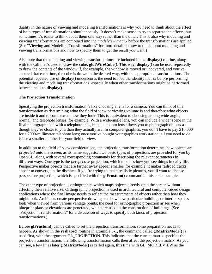
Let’s start with a simple case of two transformations: a 45-degree counterclockwise rotation about theorigin around the z-axis, and a translation down the x-axis. Suppose that the object you’re drawing issmall compared to the translation (so that you can see the effect of the translation), and that it’soriginally located at the origin. If you rotate the object first and then translate it, the rotated objectappears on the x-axis. If you translate it down the x-axis first, however, and then rotate about the origin,the object is on the line y=x, as shown in Figure 3-4. In general, the order of transformations is critical.If you do transformation A and then transformation B, you almost always get something different than ifyou do them in the opposite order.
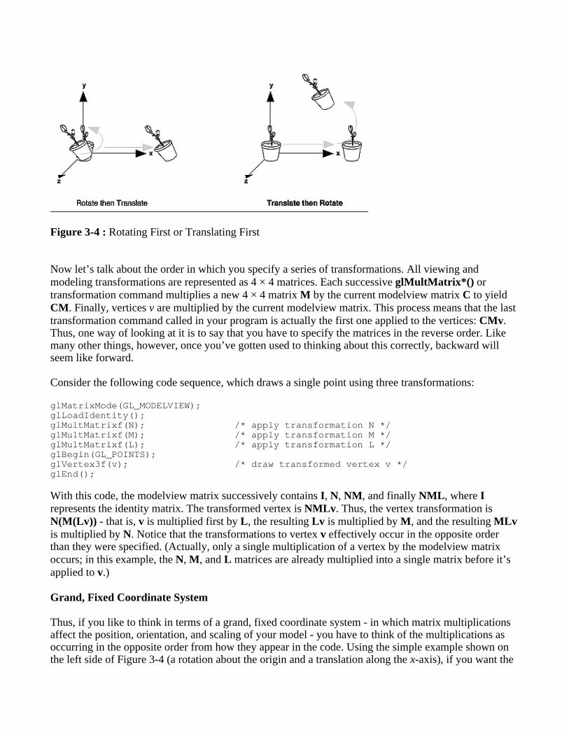
Figure 3-4 : Rotating First or Translating First
Now let’s talk about the order in which you specify a series of transformations. All viewing andmodeling transformations are represented as 4 × 4 matrices. Each successive glMultMatrix*() ortransformation command multiplies a new 4 × 4 matrix M by the current modelview matrix C to yieldCM. Finally, vertices v are multiplied by the current modelview matrix. This process means that the lasttransformation command called in your program is actually the first one applied to the vertices: CMv.Thus, one way of looking at it is to say that you have to specify the matrices in the reverse order. Likemany other things, however, once you’ve gotten used to thinking about this correctly, backward willseem like forward.
Consider the following code sequence, which draws a single point using three transformations:
glMatrixMode(GL_MODELVIEW);glLoadIdentity();glMultMatrixf(N); /* apply transformation N */glMultMatrixf(M); /* apply transformation M */glMultMatrixf(L); /* apply transformation L */glBegin(GL_POINTS);glVertex3f(v); /* draw transformed vertex v */glEnd();
With this code, the modelview matrix successively contains I, N, NM, and finally NML, where Irepresents the identity matrix. The transformed vertex is NMLv. Thus, the vertex transformation isN(M(Lv)) - that is, v is multiplied first by L, the resulting Lv is multiplied by M, and the resulting MLvis multiplied by N. Notice that the transformations to vertex v effectively occur in the opposite orderthan they were specified. (Actually, only a single multiplication of a vertex by the modelview matrixoccurs; in this example, the N, M, and L matrices are already multiplied into a single matrix before it’sapplied to v.)
Grand, Fixed Coordinate System
Thus, if you like to think in terms of a grand, fixed coordinate system - in which matrix multiplicationsaffect the position, orientation, and scaling of your model - you have to think of the multiplications asoccurring in the opposite order from how they appear in the code. Using the simple example shown onthe left side of Figure 3-4 (a rotation about the origin and a translation along the x-axis), if you want the

object to appear on the axis after the operations, the rotation must occur first, followed by thetranslation. To do this, you’ll need to reverse the order of operations, so the code looks something likethis (where R is the rotation matrix and T is the translation matrix):
glMatrixMode(GL_MODELVIEW);glLoadIdentity();glMultMatrixf(T); /* translation */glMultMatrixf(R); /* rotation */draw_the_object();
Moving a Local Coordinate System
Another way to view matrix multiplications is to forget about a grand, fixed coordinate system in whichyour model is transformed and instead imagine that a local coordinate system is tied to the object you’redrawing. All operations occur relative to this changing coordinate system. With this approach, thematrix multiplications now appear in the natural order in the code. (Regardless of which analogy you’reusing, the code is the same, but how you think about it differs.) To see this in the translation-rotationexample, begin by visualizing the object with a coordinate system tied to it. The translation operationmoves the object and its coordinate system down the x-axis. Then, the rotation occurs about the(now-translated) origin, so the object rotates in place in its position on the axis.
This approach is what you should use for applications such as articulated robot arms, where there arejoints at the shoulder, elbow, and wrist, and on each of the fingers. To figure out where the tips of thefingers go relative to the body, you’d like to start at the shoulder, go down to the wrist, and so on,applying the appropriate rotations and translations at each joint. Thinking about it in reverse would befar more confusing.
This second approach can be problematic, however, in cases where scaling occurs, and especially sowhen the scaling is nonuniform (scaling different amounts along the different axes). After uniformscaling, translations move a vertex by a multiple of what they did before, since the coordinate system isstretched. Nonuniform scaling mixed with rotations may make the axes of the local coordinate systemnonperpendicular.
As mentioned earlier, you normally issue viewing transformation commands in your program before anymodeling transformations. This way, a vertex in a model is first transformed into the desired orientationand then transformed by the viewing operation. Since the matrix multiplications must be specified inreverse order, the viewing commands need to come first. Note, however, that you don’t need to specifyeither viewing or modeling transformations if you’re satisfied with the default conditions. If there’s noviewing transformation, the "camera" is left in the default position at the origin, pointed toward thenegative z-axis; if there’s no modeling transformation, the model isn’t moved, and it retains its specifiedposition, orientation, and size.
Since the commands for performing modeling transformations can be used to perform viewingtransformations, modeling transformations are discussed first, even if viewing transformations areactually issued first. This order for discussion also matches the way many programmers think whenplanning their code: Often, they write all the code necessary to compose the scene, which involvestransformations to position and orient objects correctly relative to each other. Next, they decide wherethey want the viewpoint to be relative to the scene they’ve composed, and then they write the viewingtransformations accordingly.

Modeling Transformations
The three OpenGL routines for modeling transformations are glTranslate*(), glRotate*(), andglScale*(). As you might suspect, these routines transform an object (or coordinate system, if you’rethinking of it that way) by moving, rotating, stretching, shrinking, or reflecting it. All three commandsare equivalent to producing an appropriate translation, rotation, or scaling matrix, and then callingglMultMatrix*() with that matrix as the argument. However, these three routines might be faster thanusing glMultMatrix*(). OpenGL automatically computes the matrices for you. (See Appendix F ifyou’re interested in the details.)
In the command summaries that follow, each matrix multiplication is described in terms of what it doesto the vertices of a geometric object using the fixed coordinate system approach, and in terms of what itdoes to the local coordinate system that’s attached to an object.
Translate
void glTranslate{fd}(TYPEx, TYPE y, TYPEz);Multiplies the current matrix by a matrix that moves (translates) an object by the given x, y, and zvalues (or moves the local coordinate system by the same amounts).
Figure 3-5 shows the effect of glTranslate*().
Figure 3-5 : Translating an Object
Note that using (0.0, 0.0, 0.0) as the argument for glTranslate*() is the identity operation - that is, it hasno effect on an object or its local coordinate system.
Rotate
void glRotate{fd}(TYPE angle, TYPE x, TYPE y, TYPE z);Multiplies the current matrix by a matrix that rotates an object (or the local coordinate system) ina counterclockwise direction about the ray from the origin through the point (x, y, z). The angleparameter specifies the angle of rotation in degrees.

The effect of glRotatef(45.0, 0.0, 0.0, 1.0), which is a rotation of 45 degrees about the z-axis, is shownin Figure 3-6.
Figure 3-6 : Rotating an Object
Note that an object that lies farther from the axis of rotation is more dramatically rotated (has a largerorbit) than an object drawn near the axis. Also, if the angle argument is zero, the glRotate*() commandhas no effect.
Scale
void glScale{fd}(TYPEx, TYPE y, TYPEz);Multiplies the current matrix by a matrix that stretches, shrinks, or reflects an object along theaxes. Each x, y, and z coordinate of every point in the object is multiplied by the correspondingargument x, y, or z. With the local coordinate system approach, the local coordinate axes arestretched, shrunk, or reflected by the x, y, and z factors, and the associated object is transformedwith them.
Figure 3-7 shows the effect of glScalef(2.0, -0.5, 1.0).
Figure 3-7 : Scaling and Reflecting an Object

glScale*() is the only one of the three modeling transformations that changes the apparent size of anobject: Scaling with values greater than 1.0 stretches an object, and using values less than 1.0 shrinks it.Scaling with a -1.0 value reflects an object across an axis. The identity values for scaling are (1.0, 1.0,1.0). In general, you should limit your use of glScale*() to those cases where it is necessary. UsingglScale*() decreases the performance of lighting calculations, because the normal vectors have to berenormalized after transformation.
Note: A scale value of zero collapses all object coordinates along that axis to zero. It’s usually not agood idea to do this, because such an operation cannot be undone. Mathematically speaking, the matrixcannot be inverted, and inverse matrices are required for certain lighting operations. (See Chapter 5.)Sometimes collapsing coordinates does make sense, however; the calculation of shadows on a planarsurface is a typical application. (See "Shadows" in Chapter 14.) In general, if a coordinate system is tobe collapsed, the projection matrix should be used rather than the modelview matrix.
A Modeling Transformation Code Example
Example 3-2 is a portion of a program that renders a triangle four times, as shown in Figure 3-8. Theseare the four transformed triangles.
A solid wireframe triangle is drawn with no modeling transformation.
The same triangle is drawn again, but with a dashed line stipple and translated (to the left - alongthe negative x-axis).
A triangle is drawn with a long dashed line stipple, with its height (y-axis) halved and its width(x-axis) increased by 50%.
A rotated triangle, made of dotted lines, is drawn.
Figure 3-8 : Modeling Transformation Example
Example 3-2 : Using Modeling Transformations: model.c
glLoadIdentity();glColor3f(1.0, 1.0, 1.0);draw_triangle(); /* solid lines */
glEnable(GL_LINE_STIPPLE); /* dashed lines */glLineStipple(1, 0xF0F0); glLoadIdentity();glTranslatef(-20.0, 0.0, 0.0);draw_triangle();

glLineStipple(1, 0xF00F); /*long dashed lines */glLoadIdentity();glScalef(1.5, 0.5, 1.0);draw_triangle();
glLineStipple(1, 0x8888); /* dotted lines */glLoadIdentity();glRotatef (90.0, 0.0, 0.0, 1.0);draw_triangle ();glDisable (GL_LINE_STIPPLE);
Note the use of glLoadIdentity() to isolate the effects of modeling transformations; initializing thematrix values prevents successive transformations from having a cumulative effect. Even though usingglLoadIdentity() repeatedly has the desired effect, it may be inefficient, because you may have torespecify viewing or modeling transformations. (See "Manipulating the Matrix Stacks" for a better wayto isolate transformations.)
Note: Sometimes, programmers who want a continuously rotating object attempt to achieve this byrepeatedly applying a rotation matrix that has small values. The problem with this technique is thatbecause of round-off errors, the product of thousands of tiny rotations gradually drifts away from thevalue you really want (it might even become something that isn’t a rotation). Instead of using thistechnique, increment the angle and issue a new rotation command with the new angle at each updatestep.
Viewing Transformations
A viewing transformation changes the position and orientation of the viewpoint. If you recall the cameraanalogy, the viewing transformation positions the camera tripod, pointing the camera toward the model.Just as you move the camera to some position and rotate it until it points in the desired direction,viewing transformations are generally composed of translations and rotations. Also remember that toachieve a certain scene composition in the final image or photograph, you can either move the camera ormove all the objects in the opposite direction. Thus, a modeling transformation that rotates an objectcounterclockwise is equivalent to a viewing transformation that rotates the camera clockwise, forexample. Finally, keep in mind that the viewing transformation commands must be called before anymodeling transformations are performed, so that the modeling transformations take effect on the objectsfirst.
You can manufacture a viewing transformation in any of several ways, as described next. You can alsochoose to use the default location and orientation of the viewpoint, which is at the origin, looking downthe negative z-axis.
Use one or more modeling transformation commands (that is, glTranslate*() and glRotate*()).You can think of the effect of these transformations as moving the camera position or as movingall the objects in the world, relative to a stationary camera.
Use the Utility Library routine gluLookAt() to define a line of sight. This routine encapsulates aseries of rotation and translation commands.
Create your own utility routine that encapsulates rotations and translations. Some applicationsmight require custom routines that allow you to specify the viewing transformation in a convenient

way. For example, you might want to specify the roll, pitch, and heading rotation angles of a planein flight, or you might want to specify a transformation in terms of polar coordinates for a camerathat’s orbiting around an object.
Using glTranslate*() and glRotate*()
When you use modeling transformation commands to emulate viewing transformations, you’re trying tomove the viewpoint in a desired way while keeping the objects in the world stationary. Since theviewpoint is initially located at the origin and since objects are often most easily constructed there aswell (see Figure 3-9), in general you have to perform some transformation so that the objects can beviewed. Note that, as shown in the figure, the camera initially points down the negative z-axis. (You’reseeing the back of the camera.)
Figure 3-9 : Object and Viewpoint at the Origin
In the simplest case, you can move the viewpoint backward, away from the objects; this has the sameeffect as moving the objects forward, or away from the viewpoint. Remember that by default forward isdown the negative z-axis; if you rotate the viewpoint, forward has a different meaning. So, to put 5 unitsof distance between the viewpoint and the objects by moving the viewpoint, as shown in Figure 3-10,use
glTranslatef(0.0, 0.0, -5.0);
This routine moves the objects in the scene -5 units along the z axis. This is also equivalent to movingthe camera +5 units along the z axis.

Figure 3-10 : Separating the Viewpoint and the Object
Now suppose you want to view the objects from the side. Should you issue a rotate command before orafter the translate command? If you’re thinking in terms of a grand, fixed coordinate system, firstimagine both the object and the camera at the origin. You could rotate the object first and then move itaway from the camera so that the desired side is visible. Since you know that with the fixed coordinatesystem approach, commands have to be issued in the opposite order in which they should take effect,you know that you need to write the translate command first in your code and follow it with the rotatecommand.
Now let’s use the local coordinate system approach. In this case, think about moving the object and itslocal coordinate system away from the origin; then, the rotate command is carried out using thenow-translated coordinate system. With this approach, commands are issued in the order in whichthey’re applied, so once again the translate command comes first. Thus, the sequence of transformationcommands to produce the desired result is
glTranslatef(0.0, 0.0, -5.0);glRotatef(90.0, 0.0, 1.0, 0.0);
If you’re having trouble keeping track of the effect of successive matrix multiplications, try using boththe fixed and local coordinate system approaches and see whether one makes more sense to you. Notethat with the fixed coordinate system, rotations always occur about the grand origin, whereas with thelocal coordinate system, rotations occur about the origin of the local system. You might also try usingthe gluLookAt() utility routine described in the next section.
Using the gluLookAt() Utility Routine
Often, programmers construct a scene around the origin or some other convenient location, then theywant to look at it from an arbitrary point to get a good view of it. As its name suggests, the gluLookAt()utility routine is designed for just this purpose. It takes three sets of arguments, which specify thelocation of the viewpoint, define a reference point toward which the camera is aimed, and indicate which

direction is up. Choose the viewpoint to yield the desired view of the scene. The reference point istypically somewhere in the middle of the scene. (If you’ve built your scene at the origin, the referencepoint is probably the origin.) It might be a little trickier to specify the correct up-vector. Again, if you’vebuilt some real-world scene at or around the origin and if you’ve been taking the positive y-axis to pointupward, then that’s your up-vector for gluLookAt(). However, if you’re designing a flight simulator, upis the direction perpendicular to the plane’s wings, from the plane toward the sky when the plane isright-side up on the ground.
The gluLookAt() routine is particularly useful when you want to pan across a landscape, for instance.With a viewing volume that’s symmetric in both x and y, the (eyex, eyey, eyez) point specified is alwaysin the center of the image on the screen, so you can use a series of commands to move this point slightly,thereby panning across the scene.
void gluLookAt(GLdouble eyex, GLdouble eyey, GLdouble eyez, GLdouble centerx, GLdouble centery,GLdouble centerz, GLdouble upx, GLdouble upy, GLdouble upz);
Defines a viewing matrix and multiplies it to the right of the current matrix. The desired viewpointis specified by eyex, eyey, and eyez. The centerx, centery, and centerz arguments specify any pointalong the desired line of sight, but typically they’re some point in the center of the scene beinglooked at. The upx, upy, and upz arguments indicate which direction is up (that is, the directionfrom the bottom to the top of the viewing volume).
In the default position, the camera is at the origin, is looking down the negative z-axis, and has thepositive y-axis as straight up. This is the same as calling
gluLookat (0.0, 0.0, 0.0, 0.0, 0.0, -100.0, 0.0, 1.0, 0.0);
The z value of the reference point is -100.0, but could be any negative z, because the line of sight willremain the same. In this case, you don’t actually want to call gluLookAt(), because this is the default(see Figure 3-11) and you are already there! (The lines extending from the camera represent the viewingvolume, which indicates its field of view.)
Figure 3-11 : Default Camera Position
Figure 3-12 shows the effect of a typical gluLookAt() routine. The camera position (eyex, eyey, eyez) isat (4, 2, 1). In this case, the camera is looking right at the model, so the reference point is at (2, 4, -3).
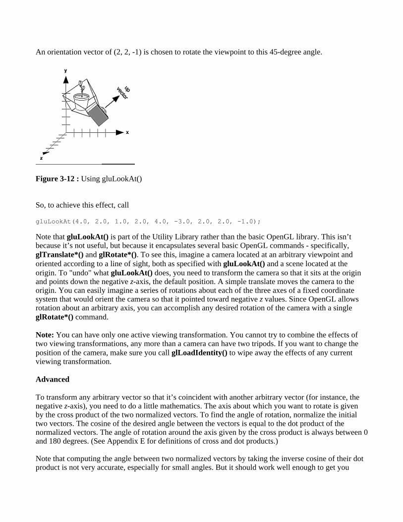
An orientation vector of (2, 2, -1) is chosen to rotate the viewpoint to this 45-degree angle.
Figure 3-12 : Using gluLookAt()
So, to achieve this effect, call
gluLookAt(4.0, 2.0, 1.0, 2.0, 4.0, -3.0, 2.0, 2.0, -1.0);
Note that gluLookAt() is part of the Utility Library rather than the basic OpenGL library. This isn’tbecause it’s not useful, but because it encapsulates several basic OpenGL commands - specifically,glTranslate*() and glRotate*(). To see this, imagine a camera located at an arbitrary viewpoint andoriented according to a line of sight, both as specified with gluLookAt() and a scene located at theorigin. To "undo" what gluLookAt() does, you need to transform the camera so that it sits at the originand points down the negative z-axis, the default position. A simple translate moves the camera to theorigin. You can easily imagine a series of rotations about each of the three axes of a fixed coordinatesystem that would orient the camera so that it pointed toward negative z values. Since OpenGL allowsrotation about an arbitrary axis, you can accomplish any desired rotation of the camera with a singleglRotate*() command.
Note: You can have only one active viewing transformation. You cannot try to combine the effects oftwo viewing transformations, any more than a camera can have two tripods. If you want to change theposition of the camera, make sure you call glLoadIdentity() to wipe away the effects of any currentviewing transformation.
Advanced
To transform any arbitrary vector so that it’s coincident with another arbitrary vector (for instance, thenegative z-axis), you need to do a little mathematics. The axis about which you want to rotate is givenby the cross product of the two normalized vectors. To find the angle of rotation, normalize the initialtwo vectors. The cosine of the desired angle between the vectors is equal to the dot product of thenormalized vectors. The angle of rotation around the axis given by the cross product is always between 0and 180 degrees. (See Appendix E for definitions of cross and dot products.)
Note that computing the angle between two normalized vectors by taking the inverse cosine of their dotproduct is not very accurate, especially for small angles. But it should work well enough to get you

started.
Creating a Custom Utility Routine
Advanced
For some specialized applications, you might want to define your own transformation routine. Since thisis rarely done and in any case is a fairly advanced topic, it’s left mostly as an exercise for the reader. Thefollowing exercises suggest two custom viewing transformations that might be useful.
Try This
Suppose you’re writing a flight simulator and you’d like to display the world from the point ofview of the pilot of a plane. The world is described in a coordinate system with the origin on therunway and the plane at coordinates (x, y, z). Suppose further that the plane has some roll , pitch,and heading (these are rotation angles of the plane relative to its center of gravity).
Show that the following routine could serve as the viewing transformation:
void pilotView{GLdouble planex, GLdouble planey, GLdouble planez, GLdouble roll, GLdouble pitch, GLdouble heading){ glRotated(roll, 0.0, 0.0, 1.0); glRotated(pitch, 0.0, 1.0, 0.0); glRotated(heading, 1.0, 0.0, 0.0); glTranslated(-planex, -planey, -planez);}
Suppose your application involves orbiting the camera around an object that’s centered at theorigin. In this case, you’d like to specify the viewing transformation by using polar coordinates.Let the distance variable define the radius of the orbit, or how far the camera is from the origin.(Initially, the camera is moved distance units along the positive z-axis.) The azimuth describes theangle of rotation of the camera about the object in the x-y plane, measured from the positive y-axis.Similarly, elevation is the angle of rotation of the camera in the y-z plane, measured from thepositive z-axis. Finally, twist represents the rotation of the viewing volume around its line of sight.
Show that the following routine could serve as the viewing transformation:
void polarView{GLdouble distance, GLdouble twist, GLdouble elevation, GLdouble azimuth){ glTranslated(0.0, 0.0, -distance); glRotated(-twist, 0.0, 0.0, 1.0); glRotated(-elevation, 1.0, 0.0, 0.0); glRotated(azimuth, 0.0, 0.0, 1.0);}
Projection Transformations

The previous section described how to compose the desired modelview matrix so that the correctmodeling and viewing transformations are applied. This section explains how to define the desiredprojection matrix, which is also used to transform the vertices in your scene. Before you issue any of thetransformation commands described in this section, remember to call
glMatrixMode(GL_PROJECTION);glLoadIdentity();
so that the commands affect the projection matrix rather than the modelview matrix and so that youavoid compound projection transformations. Since each projection transformation command completelydescribes a particular transformation, typically you don’t want to combine a projection transformationwith another transformation.
The purpose of the projection transformation is to define a viewing volume, which is used in two ways.The viewing volume determines how an object is projected onto the screen (that is, by using aperspective or an orthographic projection), and it defines which objects or portions of objects are clippedout of the final image. You can think of the viewpoint we’ve been talking about as existing at one end ofthe viewing volume. At this point, you might want to reread "A Simple Example: Drawing a Cube" forits overview of all the transformations, including projection transformations.
Perspective Projection
The most unmistakable characteristic of perspective projection is foreshortening: the farther an object isfrom the camera, the smaller it appears in the final image. This occurs because the viewing volume for aperspective projection is a frustum of a pyramid (a truncated pyramid whose top has been cut off by aplane parallel to its base). Objects that fall within the viewing volume are projected toward the apex ofthe pyramid, where the camera or viewpoint is. Objects that are closer to the viewpoint appear largerbecause they occupy a proportionally larger amount of the viewing volume than those that are fartheraway, in the larger part of the frustum. This method of projection is commonly used for animation,visual simulation, and any other applications that strive for some degree of realism because it’s similarto how our eye (or a camera) works.
The command to define a frustum, glFrustum(), calculates a matrix that accomplishes perspectiveprojection and multiplies the current projection matrix (typically the identity matrix) by it. Recall thatthe viewing volume is used to clip objects that lie outside of it; the four sides of the frustum, its top, andits base correspond to the six clipping planes of the viewing volume, as shown in Figure 3-13. Objects orparts of objects outside these planes are clipped from the final image. Note that glFrustum() doesn’trequire you to define a symmetric viewing volume.

Figure 3-13 : Perspective Viewing Volume Specified by glFrustum()
void glFrustum(GLdouble left, GLdouble right, GLdouble bottom,GLdouble top, GLdouble near, GLdouble far);
Creates a matrix for a perspective-view frustum and multiplies the current matrix by it. Thefrustum’s viewing volume is defined by the parameters: (left, bottom, -near) and (right, top, -near)specify the (x, y, z) coordinates of the lower-left and upper-right corners of the near clippingplane; near and far give the distances from the viewpoint to the near and far clipping planes.They should always be positive.
The frustum has a default orientation in three-dimensional space. You can perform rotations ortranslations on the projection matrix to alter this orientation, but this is tricky and nearly alwaysavoidable.
Advanced
Also, the frustum doesn’t have to be symmetrical, and its axis isn’t necessarily aligned with the z-axis.For example, you can use glFrustum() to draw a picture as if you were looking through a rectangularwindow of a house, where the window was above and to the right of you. Photographers use such aviewing volume to create false perspectives. You might use it to have the hardware calculate images atmuch higher than normal resolutions, perhaps for use on a printer. For example, if you want an imagethat has twice the resolution of your screen, draw the same picture four times, each time using thefrustum to cover the entire screen with one-quarter of the image. After each quarter of the image isrendered, you can read the pixels back to collect the data for the higher-resolution image. (See Chapter 8for more information about reading pixel data.)
Although it’s easy to understand conceptually, glFrustum() isn’t intuitive to use. Instead, you might trythe Utility Library routine gluPerspective(). This routine creates a viewing volume of the same shape asglFrustum() does, but you specify it in a different way. Rather than specifying corners of the nearclipping plane, you specify the angle of the field of view ( &THgr; , or theta, in Figure 3-14) in the ydirection and the aspect ratio of the width to height (x/y). (For a square portion of the screen, the aspectratio is 1.0.) These two parameters are enough to determine an untruncated pyramid along the line ofsight, as shown in Figure 3-14. You also specify the distance between the viewpoint and the near and far

clipping planes, thereby truncating the pyramid. Note that gluPerspective() is limited to creatingfrustums that are symmetric in both the x- and y-axes along the line of sight, but this is usually what youwant.
Figure 3-14 : Perspective Viewing Volume Specified by gluPerspective()
void gluPerspective(GLdouble fovy, GLdouble aspect, GLdouble near, GLdouble far);
Creates a matrix for a symmetric perspective-view frustum and multiplies the current matrix by it.fovy is the angle of the field of view in the x-z plane; its value must be in the range [0.0,180.0].aspect is the aspect ratio of the frustum, its width divided by its height. near and far values thedistances between the viewpoint and the clipping planes, along the negative z-axis. They shouldalways be positive.
Just as with glFrustum(), you can apply rotations or translations to change the default orientation of theviewing volume created by gluPerspective(). With no such transformations, the viewpoint remains atthe origin, and the line of sight points down the negative z-axis.
With gluPerspective(), you need to pick appropriate values for the field of view, or the image may lookdistorted. For example, suppose you’re drawing to the entire screen, which happens to be 11 inches high.If you choose a field of view of 90 degrees, your eye has to be about 7.8 inches from the screen for theimage to appear undistorted. (This is the distance that makes the screen subtend 90 degrees.) If your eyeis farther from the screen, as it usually is, the perspective doesn’t look right. If your drawing areaoccupies less than the full screen, your eye has to be even closer. To get a perfect field of view, figureout how far your eye normally is from the screen and how big the window is, and calculate the angle thewindow subtends at that size and distance. It’s probably smaller than you would guess. Another way tothink about it is that a 94-degree field of view with a 35-millimeter camera requires a 20-millimeter lens,which is a very wide-angle lens. (See "Troubleshooting Transformations" for more details on how tocalculate the desired field of view.)
The preceding paragraph mentions inches and millimeters - do these really have anything to do withOpenGL? The answer is, in a word, no. The projection and other transformations are inherently unitless.If you want to think of the near and far clipping planes as located at 1.0 and 20.0 meters, inches,kilometers, or leagues, it’s up to you. The only rule is that you have to use a consistent unit of

measurement. Then the resulting image is drawn to scale.
Orthographic Projection
With an orthographic projection, the viewing volume is a rectangular parallelepiped, or more informally,a box (see Figure 3-15). Unlike perspective projection, the size of the viewing volume doesn’t changefrom one end to the other, so distance from the camera doesn’t affect how large an object appears. Thistype of projection is used for applications such as creating architectural blueprints and computer-aideddesign, where it’s crucial to maintain the actual sizes of objects and angles between them as they’reprojected.
Figure 3-15 : Orthographic Viewing Volume
The command glOrtho() creates an orthographic parallel viewing volume. As with glFrustum(), youspecify the corners of the near clipping plane and the distance to the far clipping plane.
void glOrtho(GLdouble left, GLdouble right, GLdouble bottom, GLdouble top, GLdouble near, GLdouble far);
Creates a matrix for an orthographic parallel viewing volume and multiplies the current matrix byit. (left, bottom, -near) and (right, top, -near) are points on the near clipping plane that aremapped to the lower-left and upper-right corners of the viewport window, respectively. (left,bottom, -far) and (right, top, -far) are points on the far clipping plane that are mapped to the samerespective corners of the viewport. Both near and far can be positive or negative.
With no other transformations, the direction of projection is parallel to the z-axis, and the viewpointfaces toward the negative z-axis. Note that this means that the values passed in for far and near are usedas negative z values if these planes are in front of the viewpoint, and positive if they’re behind theviewpoint.
For the special case of projecting a two-dimensional image onto a two-dimensional screen, use theUtility Library routine gluOrtho2D(). This routine is identical to the three-dimensional version,glOrtho(), except that all the z coordinates for objects in the scene are assumed to lie between -1.0 and1.0. If you’re drawing two-dimensional objects using the two-dimensional vertex commands, all the zcoordinates are zero; thus, none of the objects are clipped because of their z values.

void gluOrtho2D(GLdouble left, GLdouble right, GLdouble bottom, GLdouble top);
Creates a matrix for projecting two-dimensional coordinates onto the screen and multiplies thecurrent projection matrix by it. The clipping region is a rectangle with the lower-left corner at(left, bottom) and the upper-right corner at (right, top).
Viewing Volume Clipping
After the vertices of the objects in the scene have been transformed by the modelview and projectionmatrices, any primitives that lie outside the viewing volume are clipped. The six clipping planes used arethose that define the sides and ends of the viewing volume. You can specify additional clipping planesand locate them wherever you choose. (See "Additional Clipping Planes" for information about thisrelatively advanced topic.) Keep in mind that OpenGL reconstructs the edges of polygons that getclipped.
Viewport Transformation
Recalling the camera analogy, you know that the viewport transformation corresponds to the stagewhere the size of the developed photograph is chosen. Do you want a wallet-size or a poster-sizephotograph? Since this is computer graphics, the viewport is the rectangular region of the window wherethe image is drawn. Figure 3-16 shows a viewport that occupies most of the screen. The viewport ismeasured in window coordinates, which reflect the position of pixels on the screen relative to thelower-left corner of the window. Keep in mind that all vertices have been transformed by the modelviewand projection matrices by this point, and vertices outside the viewing volume have been clipped.
Figure 3-16 : Viewport Rectangle
Defining the Viewport
The window system, not OpenGL, is responsible for opening a window on the screen. However, bydefault the viewport is set to the entire pixel rectangle of the window that’s opened. You use theglViewport() command to choose a smaller drawing region; for example, you can subdivide the windowto create a split-screen effect for multiple views in the same window.
void glViewport(GLint x, GLint y, GLsizei width, GLsizei height);

Defines a pixel rectangle in the window into which the final image is mapped. The (x, y) parameterspecifies the lower-left corner of the viewport, and width and height are the size of the viewportrectangle. By default, the initial viewport values are (0, 0, winWidth, winHeight), where winWidthand winHeight are the size of the window.
The aspect ratio of a viewport should generally equal the aspect ratio of the viewing volume. If the tworatios are different, the projected image will be distorted when mapped to the viewport, as shown inFigure 3-17. Note that subsequent changes to the size of the window don’t explicitly affect the viewport.Your application should detect window resize events and modify the viewport appropriately.
Figure 3-17 : Mapping the Viewing Volume to the Viewport
In Figure 3-17, the left figure shows a projection that maps a square image onto a square viewport usingthese routines:
gluPerspective(fovy, 1.0, near, far); glViewport(0, 0, 400, 400);
However, in the right figure, the window has been resized to a nonequilateral rectangular viewport, butthe projection is unchanged. The image appears compressed along the x-axis.
gluPerspective(fovy, 1.0, near, far);glViewport (0, 0, 400, 200);
To avoid the distortion, modify the aspect ratio of the projection to match the viewport:
gluPerspective(fovy, 2.0, near, far);glViewport(0, 0, 400, 200);
Try This
Modify an existing program so that an object is drawn twice, in different viewports. You might draw the

object with different projection and/or viewing transformations for each viewport. To create twoside-by-side viewports, you might issue these commands, along with the appropriate modeling, viewing,and projection transformations:
glViewport (0, 0, sizex/2, sizey); . . . glViewport (sizex/2, 0, sizex/2, sizey);
The Transformed Depth Coordinate
The depth (z) coordinate is encoded during the viewport transformation (and later stored in the depthbuffer). You can scale z values to lie within a desired range with the glDepthRange() command.(Chapter 10 discusses the depth buffer and the corresponding uses for the depth coordinate.) Unlike xand y window coordinates, z window coordinates are treated by OpenGL as though they always rangefrom 0.0 to 1.0.
void glDepthRange(GLclampd near, GLclampd far);Defines an encoding for z coordinates that’s performed during the viewport transformation. Thenear and far values represent adjustments to the minimum and maximum values that can be storedin the depth buffer. By default, they’re 0.0 and 1.0, respectively, which work for most applications.These parameters are clamped to lie within [0,1].
In perspective projection, the transformed depth coordinate (like the x and y coordinates) is subject toperspective division by the w coordinate. As the transformed depth coordinate moves farther away fromthe near clipping plane, its location becomes increasingly less precise. (See Figure 3-18.)
Figure 3-18 : Perspective Projection and Transformed Depth Coordinates
Therefore, perspective division affects the accuracy of operations which rely upon the transformed depthcoordinate, especially depth-buffering, which is used for hidden surface removal.
Troubleshooting Transformations
It’s pretty easy to get a camera pointed in the right direction, but in computer graphics, you have tospecify position and direction with coordinates and angles. As we can attest, it’s all too easy to achieve

the well-known black-screen effect. Although any number of things can go wrong, often you get thiseffect - which results in absolutely nothing being drawn in the window you open on the screen - fromincorrectly aiming the "camera" and taking a picture with the model behind you. A similar problemarises if you don’t choose a field of view that’s wide enough to view your objects but narrow enough sothey appear reasonably large.
If you find yourself exerting great programming effort only to create a black window, try thesediagnostic steps.
1. Check the obvious possibilities. Make sure your system is plugged in. Make sure you’re drawingyour objects with a color that’s different from the color with which you’re clearing the screen.Make sure that whatever states you’re using (such as lighting, texturing, alpha blending, logicaloperations, or antialiasing) are correctly turned on or off, as desired.
2. Remember that with the projection commands, the near and far coordinates measure distance fromthe viewpoint and that (by default) you’re looking down the negative z axis. Thus, if the near valueis 1.0 and the far 3.0, objects must have z coordinates between -1.0 and -3.0 in order to be visible.To ensure that you haven’t clipped everything out of your scene, temporarily set the near and farclipping planes to some absurdly inclusive values, such as 0.001 and 1000000.0. This altersappearance for operations such as depth-buffering and fog, but it might uncover inadvertentlyclipped objects.
3. Determine where the viewpoint is, in which direction you’re looking, and where your objects are.It might help to create a real three-dimensional space - using your hands, for instance - to figurethese things out.
4. Make sure you know where you’re rotating about. You might be rotating about some arbitrarylocation unless you translated back to the origin first. It’s OK to rotate about any point unlessyou’re expecting to rotate about the origin.
5. Check your aim. Use gluLookAt() to aim the viewing volume at your objects. Or draw yourobjects at or near the origin, and use glTranslate*() as a viewing transformation to move thecamera far enough in the z direction only so that the objects fall within the viewing volume. Onceyou’ve managed to make your objects visible, try to change the viewing volume incrementally toachieve the exact result you want, as described next.
Even after you’ve aimed the camera in the correct direction and you can see your objects, they mightappear too small or too large. If you’re using gluPerspective(), you might need to alter the angledefining the field of view by changing the value of the first parameter for this command. You can usetrigonometry to calculate the desired field of view given the size of the object and its distance from theviewpoint: The tangent of half the desired angle is half the size of the object divided by the distance tothe object (see Figure 3-19). Thus, you can use an arctangent routine to compute half the desired angle.Example 3-3 assumes such a routine, atan2(), which calculates the arctangent given the length of theopposite and adjacent sides of a right triangle. This result then needs to be converted from radians todegrees.

Figure 3-19 : Using Trigonometry to Calculate the Field of View
Example 3-3 : Calculating Field of View
#define PI 3.1415926535
double calculateAngle(double size, double distance){ double radtheta, degtheta;
radtheta = 2.0 * atan2 (size/2.0, distance); degtheta = (180.0 * radtheta) / PI; return (degtheta);}
Of course, typically you don’t know the exact size of an object, and the distance can only be determinedbetween the viewpoint and a single point in your scene. To obtain a fairly good approximate value, findthe bounding box for your scene by determining the maximum and minimum x, y, and z coordinates ofall the objects in your scene. Then calculate the radius of a bounding sphere for that box, and use thecenter of the sphere to determine the distance and the radius to determine the size.
For example, suppose all the coordinates in your object satisfy the equations -1 ≤ x ≤ 3, 5 ≤ y≤ 7, and -5 ≤ z ≤ 5. Then the center of the bounding box is (1, 6, 0), and the radius of abounding sphere is the distance from the center of the box to any corner - say (3, 7, 5) - or
If the viewpoint is at (8, 9, 10), the distance between it and the center is
The tangent of the half angle is 5.477 divided by 12.570, which equals 0.4357, so the half angle is 23.54degrees.
Remember that the field-of-view angle affects the optimal position for the viewpoint, if you’re trying toachieve a realistic image. For example, if your calculations indicate that you need a 179-degree field of

view, the viewpoint must be a fraction of an inch from the screen to achieve realism. If your calculatedfield of view is too large, you might need to move the viewpoint farther away from the object.
Manipulating the Matrix Stacks
The modelview and projection matrices you’ve been creating, loading, and multiplying have only beenthe visible tips of their respective icebergs. Each of these matrices is actually the topmost member of astack of matrices (see Figure 3-20).
Figure 3-20 : Modelview and Projection Matrix Stacks
A stack of matrices is useful for constructing hierarchical models, in which complicated objects areconstructed from simpler ones. For example, suppose you’re drawing an automobile that has fourwheels, each of which is attached to the car with five bolts. You have a single routine to draw a wheeland another to draw a bolt, since all the wheels and all the bolts look the same. These routines draw awheel or a bolt in some convenient position and orientation, say centered at the origin with its axiscoincident with the z axis. When you draw the car, including the wheels and bolts, you want to call thewheel-drawing routine four times with different transformations in effect each time to position thewheels correctly. As you draw each wheel, you want to draw the bolts five times, each time translatedappropriately relative to the wheel.
Suppose for a minute that all you have to do is draw the car body and the wheels. The Englishdescription of what you want to do might be something like this:
Draw the car body. Remember where you are, and translate to the right front wheel. Draw thewheel and throw away the last translation so your current position is back at the origin of the carbody. Remember where you are, and translate to the left front wheel....
Similarly, for each wheel, you want to draw the wheel, remember where you are, and successivelytranslate to each of the positions that bolts are drawn, throwing away the transformations after each boltis drawn.
Since the transformations are stored as matrices, a matrix stack provides an ideal mechanism for doingthis sort of successive remembering, translating, and throwing away. All the matrix operations that havebeen described so far (glLoadMatrix(), glMultMatrix(), glLoadIdentity() and the commands that

create specific transformation matrices) deal with the current matrix, or the top matrix on the stack. Youcan control which matrix is on top with the commands that perform stack operations: glPushMatrix(),which copies the current matrix and adds the copy to the top of the stack, and glPopMatrix(), whichdiscards the top matrix on the stack, as shown in Figure 3-21. (Remember that the current matrix isalways the matrix on the top.) In effect, glPushMatrix() means "remember where you are" andglPopMatrix() means "go back to where you were."
Figure 3-21 : Pushing and Popping the Matrix Stack
void glPushMatrix(void);Pushes all matrices in the current stack down one level. The current stack is determined byglMatrixMode(). The topmost matrix is copied, so its contents are duplicated in both the top andsecond-from-the-top matrix. If too many matrices are pushed, an error is generated.
void glPopMatrix(void);Pops the top matrix off the stack, destroying the contents of the popped matrix. What was thesecond-from-the-top matrix becomes the top matrix. The current stack is determined byglMatrixMode(). If the stack contains a single matrix, calling glPopMatrix() generates an error.
Example 3-4 draws an automobile, assuming the existence of routines that draw the car body, a wheel,and a bolt.
Example 3-4 : Pushing and Popping the Matrix
draw_wheel_and_bolts(){ long i;
draw_wheel(); for(i=0;i<5;i++){ glPushMatrix(); glRotatef(72.0*i,0.0,0.0,1.0); glTranslatef(3.0,0.0,0.0); draw_bolt(); glPopMatrix(); }}
draw_body_and_wheel_and_bolts(){ draw_car_body(); glPushMatrix(); glTranslatef(40,0,30); /*move to first wheel position*/

draw_wheel_and_bolts(); glPopMatrix(); glPushMatrix(); glTranslatef(40,0,-30); /*move to 2nd wheel position*/ draw_wheel_and_bolts(); glPopMatrix(); ... /*draw last two wheels similarly*/}
This code assumes the wheel and bolt axes are coincident with the z-axis, that the bolts are evenlyspaced every 72 degrees, 3 units (maybe inches) from the center of the wheel, and that the front wheelsare 40 units in front of and 30 units to the right and left of the car’s origin.
A stack is more efficient than an individual matrix, especially if the stack is implemented in hardware.When you push a matrix, you don’t need to copy the current data back to the main process, and thehardware may be able to copy more than one element of the matrix at a time. Sometimes you might wantto keep an identity matrix at the bottom of the stack so that you don’t need to call glLoadIdentity()repeatedly.
The Modelview Matrix Stack
As you’ve seen earlier in "Viewing and Modeling Transformations," the modelview matrix contains thecumulative product of multiplying viewing and modeling transformation matrices. Each viewing ormodeling transformation creates a new matrix that multiplies the current modelview matrix; the result,which becomes the new current matrix, represents the composite transformation. The modelview matrixstack contains at least thirty-two 4 × 4 matrices; initially, the topmost matrix is the identity matrix. Someimplementations of OpenGL may support more than thirty-two matrices on the stack. To find themaximum allowable number of matrices, you can use the query commandglGetIntegerv(GL_MAX_MODELVIEW_STACK_DEPTH, GLint * params).
The Projection Matrix Stack
The projection matrix contains a matrix for the projection transformation, which describes the viewingvolume. Generally, you don’t want to compose projection matrices, so you issue glLoadIdentity()before performing a projection transformation. Also for this reason, the projection matrix stack need beonly two levels deep; some OpenGL implementations may allow more than two 4 × 4 matrices. To findthe stack depth, call glGetIntegerv(GL_MAX_PROJECTION_STACK_DEPTH, GLint * params).
One use for a second matrix in the stack would be an application that needs to display a help windowwith text in it, in addition to its normal window showing a three-dimensional scene. Since text is mosteasily positioned with an orthographic projection, you could change temporarily to an orthographicprojection, display the help, and then return to your previous projection:
glMatrixMode(GL_PROJECTION);glPushMatrix(); /*save the current projection*/ glLoadIdentity(); glOrtho(...); /*set up for displaying help*/ display_the_help();glPopMatrix();
Note that you’d probably have to also change the modelview matrix appropriately.

Advanced
If you know enough mathematics, you can create custom projection matrices that perform arbitraryprojective transformations. For example, the OpenGL and its Utility Library have no built-in mechanismfor two-point perspective. If you were trying to emulate the drawings in drafting texts, you might needsuch a projection matrix.
Additional Clipping Planes
In addition to the six clipping planes of the viewing volume (left, right, bottom, top, near, and far), youcan define up to six additional clipping planes to further restrict the viewing volume, as shown in Figure3-22. This is useful for removing extraneous objects in a scene - for example, if you want to display acutaway view of an object.
Each plane is specified by the coefficients of its equation: Ax+By+Cz+D = 0. The clipping planes areautomatically transformed appropriately by modeling and viewing transformations. The clipping volumebecomes the intersection of the viewing volume and all half-spaces defined by the additional clippingplanes. Remember that polygons that get clipped automatically have their edges reconstructedappropriately by OpenGL.
Figure 3-22 : Additional Clipping Planes and the Viewing Volume
void glClipPlane(GLenum plane, const GLdouble *equation);Defines a clipping plane. The equation argument points to the four coefficients of the planeequation, Ax+By+Cz+D = 0. All points with eye coordinates (xe, ye, ze, we) that satisfy (A B CD)M-1 (xe ye ze we)T >= 0 lie in the half-space defined by the plane, where M is the currentmodelview matrix at the time glClipPlane() is called. All points not in this half-space are clippedaway. The plane argument is GL_CLIP_PLANEi, where i is an integer specifying which of theavailable clipping planes to define. i is a number between 0 and one less than the maximumnumber of additional clipping planes.
You need to enable each additional clipping plane you define:
glEnable(GL_CLIP_PLANEi);

You can disable a plane with
glDisable(GL_CLIP_PLANEi);
All implementations of OpenGL must support at least six additional clipping planes, although someimplementations may allow more. You can use glGetIntegerv() with GL_MAX_CLIP_PLANES to findhow many clipping planes are supported.
Note: Clipping performed as a result of glClipPlane() is done in eye coordinates, not in clipcoordinates. This difference is noticeable if the projection matrix is singular (that is, a real projectionmatrix that flattens three-dimensional coordinates to two-dimensional ones). Clipping performed in eyecoordinates continues to take place in three dimensions even when the projection matrix is singular.
A Clipping Plane Code Example
Example 3-5 renders a wireframe sphere with two clipping planes that slice away three-quarters of theoriginal sphere, as shown in Figure 3-23.
Figure 3-23 : Clipped Wireframe Sphere
Example 3-5 : Wireframe Sphere with Two Clipping Planes: clip.c
#include <GL/gl.h>#include <GL/glu.h>#include <GL/glut.h>
void init(void) { glClearColor (0.0, 0.0, 0.0, 0.0); glShadeModel (GL_FLAT);}
void display(void){ GLdouble eqn[4] = {0.0, 1.0, 0.0, 0.0}; GLdouble eqn2[4] = {1.0, 0.0, 0.0, 0.0};
glClear(GL_COLOR_BUFFER_BIT); glColor3f (1.0, 1.0, 1.0); glPushMatrix(); glTranslatef (0.0, 0.0, -5.0);
/* clip lower half -- y < 0 */ glClipPlane (GL_CLIP_PLANE0, eqn); glEnable (GL_CLIP_PLANE0);

/* clip left half -- x < 0 */ glClipPlane (GL_CLIP_PLANE1, eqn2); glEnable (GL_CLIP_PLANE1);
glRotatef (90.0, 1.0, 0.0, 0.0); glutWireSphere(1.0, 20, 16); glPopMatrix(); glFlush ();}
void reshape (int w, int h){ glViewport (0, 0, (GLsizei) w, (GLsizei) h); glMatrixMode (GL_PROJECTION); glLoadIdentity (); gluPerspective(60.0, (GLfloat) w/(GLfloat) h, 1.0, 20.0); glMatrixMode (GL_MODELVIEW);}
int main(int argc, char** argv){ glutInit(&argc, argv); glutInitDisplayMode (GLUT_SINGLE | GLUT_RGB); glutInitWindowSize (500, 500); glutInitWindowPosition (100, 100); glutCreateWindow (argv[0]); init (); glutDisplayFunc(display); glutReshapeFunc(reshape); glutMainLoop(); return 0;}
Try This
Try changing the coefficients that describe the clipping planes in Example 3-5.
Try calling a modeling transformation, such as glRotate*(), to affect glClipPlane(). Make theclipping plane move independently of the objects in the scene.
Examples of Composing Several Transformations
This section demonstrates how to combine several transformations to achieve a particular result. Thetwo examples discussed are a solar system, in which objects need to rotate on their axes as well as inorbit around each other, and a robot arm, which has several joints that effectively transform coordinatesystems as they move relative to each other.
Building a Solar System
The program described in this section draws a simple solar system with a planet and a sun, both usingthe same sphere-drawing routine. To write this program, you need to use glRotate*() for the revolutionof the planet around the sun and for the rotation of the planet around its own axis. You also need
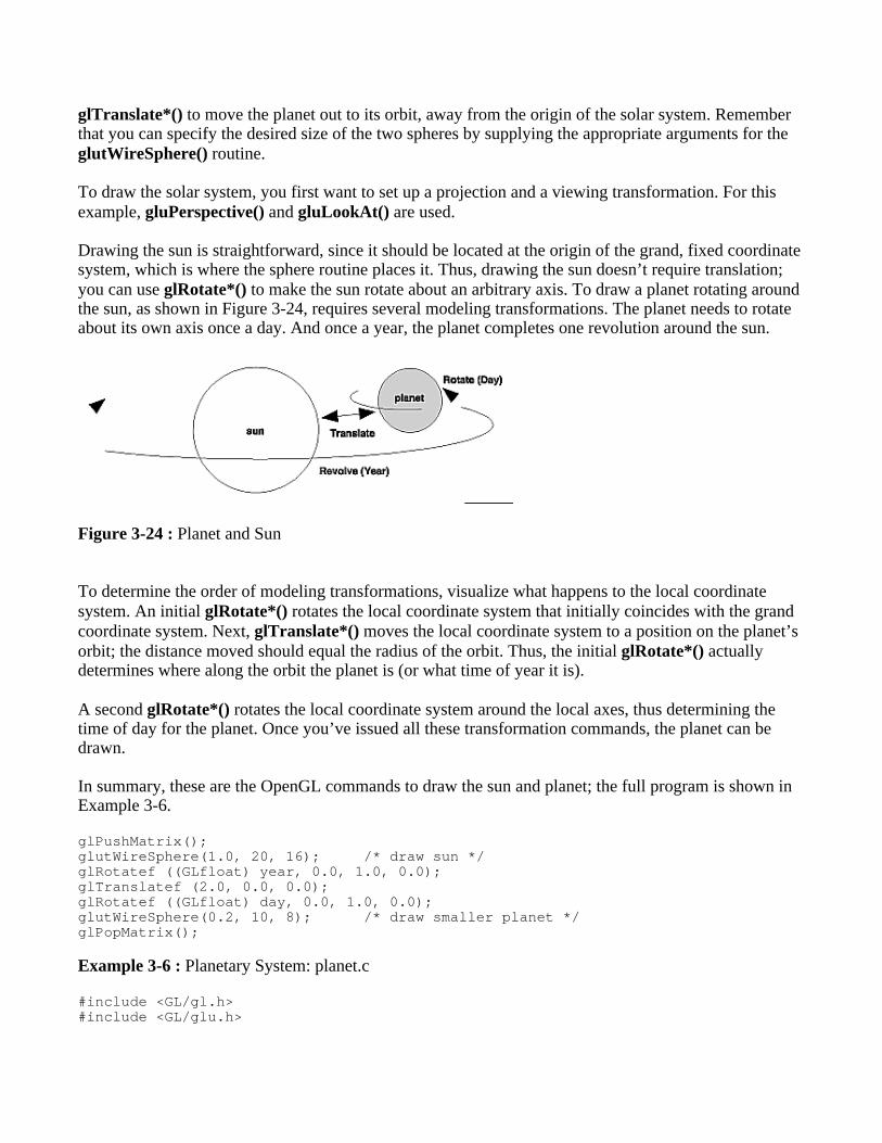
glTranslate*() to move the planet out to its orbit, away from the origin of the solar system. Rememberthat you can specify the desired size of the two spheres by supplying the appropriate arguments for theglutWireSphere() routine.
To draw the solar system, you first want to set up a projection and a viewing transformation. For thisexample, gluPerspective() and gluLookAt() are used.
Drawing the sun is straightforward, since it should be located at the origin of the grand, fixed coordinatesystem, which is where the sphere routine places it. Thus, drawing the sun doesn’t require translation;you can use glRotate*() to make the sun rotate about an arbitrary axis. To draw a planet rotating aroundthe sun, as shown in Figure 3-24, requires several modeling transformations. The planet needs to rotateabout its own axis once a day. And once a year, the planet completes one revolution around the sun.
Figure 3-24 : Planet and Sun
To determine the order of modeling transformations, visualize what happens to the local coordinatesystem. An initial glRotate*() rotates the local coordinate system that initially coincides with the grandcoordinate system. Next, glTranslate*() moves the local coordinate system to a position on the planet’sorbit; the distance moved should equal the radius of the orbit. Thus, the initial glRotate*() actuallydetermines where along the orbit the planet is (or what time of year it is).
A second glRotate*() rotates the local coordinate system around the local axes, thus determining thetime of day for the planet. Once you’ve issued all these transformation commands, the planet can bedrawn.
In summary, these are the OpenGL commands to draw the sun and planet; the full program is shown inExample 3-6.
glPushMatrix();glutWireSphere(1.0, 20, 16); /* draw sun */glRotatef ((GLfloat) year, 0.0, 1.0, 0.0);glTranslatef (2.0, 0.0, 0.0);glRotatef ((GLfloat) day, 0.0, 1.0, 0.0);glutWireSphere(0.2, 10, 8); /* draw smaller planet */glPopMatrix();
Example 3-6 : Planetary System: planet.c
#include <GL/gl.h>#include <GL/glu.h>

#include <GL/glut.h>
static int year = 0, day = 0;
void init(void) { glClearColor (0.0, 0.0, 0.0, 0.0); glShadeModel (GL_FLAT);}
void display(void){ glClear (GL_COLOR_BUFFER_BIT); glColor3f (1.0, 1.0, 1.0);
glPushMatrix(); glutWireSphere(1.0, 20, 16); /* draw sun */ glRotatef ((GLfloat) year, 0.0, 1.0, 0.0); glTranslatef (2.0, 0.0, 0.0); glRotatef ((GLfloat) day, 0.0, 1.0, 0.0); glutWireSphere(0.2, 10, 8); /* draw smaller planet */ glPopMatrix(); glutSwapBuffers();}
void reshape (int w, int h){ glViewport (0, 0, (GLsizei) w, (GLsizei) h); glMatrixMode (GL_PROJECTION); glLoadIdentity (); gluPerspective(60.0, (GLfloat) w/(GLfloat) h, 1.0, 20.0); glMatrixMode(GL_MODELVIEW); glLoadIdentity(); gluLookAt (0.0, 0.0, 5.0, 0.0, 0.0, 0.0, 0.0, 1.0, 0.0);}
void keyboard (unsigned char key, int x, int y){ switch (key) { case ‘d’: day = (day + 10) % 360; glutPostRedisplay(); break; case ‘D’: day = (day - 10) % 360; glutPostRedisplay(); break; case ‘y’: year = (year + 5) % 360; glutPostRedisplay(); break; case ‘Y’: year = (year - 5) % 360; glutPostRedisplay(); break; default: break; }}
int main(int argc, char** argv)

{ glutInit(&argc, argv); glutInitDisplayMode (GLUT_DOUBLE | GLUT_RGB); glutInitWindowSize (500, 500); glutInitWindowPosition (100, 100); glutCreateWindow (argv[0]); init (); glutDisplayFunc(display); glutReshapeFunc(reshape); glutKeyboardFunc(keyboard); glutMainLoop(); return 0;}
Try This
Try adding a moon to the planet. Or try several moons and additional planets. Hint: UseglPushMatrix() and glPopMatrix() to save and restore the position and orientation of thecoordinate system at appropriate moments. If you’re going to draw several moons around a planet,you need to save the coordinate system prior to positioning each moon and restore the coordinatesystem after each moon is drawn.
Try tilting the planet’s axis.
Building an Articulated Robot Arm
This section discusses a program that creates an articulated robot arm with two or more segments. Thearm should be connected with pivot points at the shoulder, elbow, or other joints. Figure 3-25 shows asingle joint of such an arm.
Figure 3-25 : Robot Arm
You can use a scaled cube as a segment of the robot arm, but first you must call the appropriatemodeling transformations to orient each segment. Since the origin of the local coordinate system isinitially at the center of the cube, you need to move the local coordinate system to one edge of the cube.Otherwise, the cube rotates about its center rather than the pivot point.
After you call glTranslate*() to establish the pivot point and glRotate*() to pivot the cube, translateback to the center of the cube. Then the cube is scaled (flattened and widened) before it is drawn. TheglPushMatrix() and glPopMatrix() restrict the effect of glScale*(). Here’s what your code might looklike for this first segment of the arm (the entire program is shown in Example 3-7):
glTranslatef (-1.0, 0.0, 0.0);glRotatef ((GLfloat) shoulder, 0.0, 0.0, 1.0);glTranslatef (1.0, 0.0, 0.0);
glPushMatrix();glScalef (2.0, 0.4, 1.0);glutWireCube (1.0);glPopMatrix();
To build a second segment, you need to move the local coordinate system to the next pivot point. Sincethe coordinate system has previously been rotated, the x-axis is already oriented along the length of therotated arm. Therefore, translating along the x-axis moves the local coordinate system to the next pivotpoint. Once it’s at that pivot point, you can use the same code to draw the second segment as you usedfor the first one. This can be continued for an indefinite number of segments (shoulder, elbow, wrist,fingers).
glTranslatef (1.0, 0.0, 0.0); glRotatef ((GLfloat) elbow, 0.0, 0.0, 1.0);glTranslatef (1.0, 0.0, 0.0);glPushMatrix();glScalef (2.0, 0.4, 1.0);glutWireCube (1.0);glPopMatrix();
Example 3-7 : Robot Arm: robot.c
#include <GL/gl.h>#include <GL/glu.h>#include <GL/glut.h>
static int shoulder = 0, elbow = 0;
void init(void) { glClearColor (0.0, 0.0, 0.0, 0.0); glShadeModel (GL_FLAT);}
void display(void){ glClear (GL_COLOR_BUFFER_BIT); glPushMatrix(); glTranslatef (-1.0, 0.0, 0.0); glRotatef ((GLfloat) shoulder, 0.0, 0.0, 1.0); glTranslatef (1.0, 0.0, 0.0); glPushMatrix(); glScalef (2.0, 0.4, 1.0); glutWireCube (1.0); glPopMatrix();
glTranslatef (1.0, 0.0, 0.0); glRotatef ((GLfloat) elbow, 0.0, 0.0, 1.0); glTranslatef (1.0, 0.0, 0.0); glPushMatrix(); glScalef (2.0, 0.4, 1.0); glutWireCube (1.0); glPopMatrix();
glPopMatrix(); glutSwapBuffers();}
void reshape (int w, int h)

{ glViewport (0, 0, (GLsizei) w, (GLsizei) h); glMatrixMode (GL_PROJECTION); glLoadIdentity (); gluPerspective(65.0, (GLfloat) w/(GLfloat) h, 1.0, 20.0); glMatrixMode(GL_MODELVIEW); glLoadIdentity(); glTranslatef (0.0, 0.0, -5.0);}
void keyboard (unsigned char key, int x, int y){ switch (key) { case ‘s’: /* s key rotates at shoulder */ shoulder = (shoulder + 5) % 360; glutPostRedisplay(); break; case ‘S’: shoulder = (shoulder - 5) % 360; glutPostRedisplay(); break; case ‘e’: /* e key rotates at elbow */ elbow = (elbow + 5) % 360; glutPostRedisplay(); break; case ‘E’: elbow = (elbow - 5) % 360; glutPostRedisplay(); break; default: break; }}
int main(int argc, char** argv){ glutInit(&argc, argv); glutInitDisplayMode (GLUT_DOUBLE | GLUT_RGB); glutInitWindowSize (500, 500); glutInitWindowPosition (100, 100); glutCreateWindow (argv[0]); init (); glutDisplayFunc(display); glutReshapeFunc(reshape); glutKeyboardFunc(keyboard); glutMainLoop(); return 0;}
Try This
Modify Example 3-7 to add additional segments onto the robot arm.
Modify Example 3-7 to add additional segments at the same position. For example, give the robotarm several "fingers" at the wrist, as shown in Figure 3-26. Hint: Use glPushMatrix() andglPopMatrix() to save and restore the position and orientation of the coordinate system at thewrist. If you’re going to draw fingers at the wrist, you need to save the current matrix prior topositioning each finger and restore the current matrix after each finger is drawn.

Figure 3-26 : Robot Arm with Fingers
Reversing or Mimicking Transformations
The geometric processing pipeline is very good at using viewing and projection matrices and a viewportfor clipping to transform the world (or object) coordinates of a vertex into window (or screen)coordinates. However, there are situations in which you want to reverse that process. A commonsituation is when an application user utilizes the mouse to choose a location in three dimensions. Themouse returns only a two-dimensional value, which is the screen location of the cursor. Therefore, theapplication will have to reverse the transformation process to determine from where inthree-dimensional space this screen location originated.
The Utility Library routine gluUnProject() performs this reversal of the transformations. Given thethree-dimensional window coordinates for a location and all the transformations that affected them,gluUnProject() returns the world coordinates from where it originated.
int gluUnProject(GLdouble winx, GLdouble winy, GLdouble winz, const GLdouble modelMatrix[16],const GLdouble projMatrix[16], const GLint viewport[4], GLdouble *objx, GLdouble *objy, GLdouble*objz);
Map the specified window coordinates (winx, winy, winz) into object coordinates, usingtransformations defined by a modelview matrix (modelMatrix), projection matrix (projMatrix),and viewport (viewport). The resulting object coordinates are returned in objx, objy, and objz. Thefunction returns GL_TRUE, indicating success, or GL_FALSE, indicating failure (such as annoninvertible matrix). This operation does not attempt to clip the coordinates to the viewport oreliminate depth values that fall outside of glDepthRange().
There are inherent difficulties in trying to reverse the transformation process. A two-dimensional screenlocation could have originated from anywhere on an entire line in three-dimensional space. Todisambiguate the result, gluUnProject() requires that a window depth coordinate (winz) be provided andthat winz be specified in terms of glDepthRange(). For the default values of glDepthRange(), winz at0.0 will request the world coordinates of the transformed point at the near clipping plane, while winz at1.0 will request the point at the far clipping plane.
Example 3-8 demonstrates gluUnProject() by reading the mouse position and determining thethree-dimensional points at the near and far clipping planes from which it was transformed. The

computed world coordinates are printed to standard output, but the rendered window itself is just black.
Example 3-8 : Reversing the Geometric Processing Pipeline: unproject.c
#include <GL/gl.h>#include <GL/glu.h>#include <GL/glut.h>#include <stdlib.h>#include <stdio.h>
void display(void){ glClear(GL_COLOR_BUFFER_BIT); glFlush();}
void reshape(int w, int h){ glViewport (0, 0, (GLsizei) w, (GLsizei) h); glMatrixMode(GL_PROJECTION); glLoadIdentity(); gluPerspective (45.0, (GLfloat) w/(GLfloat) h, 1.0, 100.0); glMatrixMode(GL_MODELVIEW); glLoadIdentity();}
void mouse(int button, int state, int x, int y) { GLint viewport[4]; GLdouble mvmatrix[16], projmatrix[16]; GLint realy; /* OpenGL y coordinate position */ GLdouble wx, wy, wz; /* returned world x, y, z coords */
switch (button) { case GLUT_LEFT_BUTTON: if (state == GLUT_DOWN) { glGetIntegerv (GL_VIEWPORT, viewport); glGetDoublev (GL_MODELVIEW_MATRIX, mvmatrix); glGetDoublev (GL_PROJECTION_MATRIX, projmatrix);/* note viewport[3] is height of window in pixels */ realy = viewport[3] - (GLint) y - 1; printf ("Coordinates at cursor are (%4d, %4d)\n", x, realy); gluUnProject ((GLdouble) x, (GLdouble) realy, 0.0, mvmatrix, projmatrix, viewport, &wx, &wy, &wz); printf ("World coords at z=0.0 are (%f, %f, %f)\n", wx, wy, wz); gluUnProject ((GLdouble) x, (GLdouble) realy, 1.0, mvmatrix, projmatrix, viewport, &wx, &wy, &wz); printf ("World coords at z=1.0 are (%f, %f, %f)\n", wx, wy, wz); } break; case GLUT_RIGHT_BUTTON: if (state == GLUT_DOWN) exit(0); break; default: break; }

}
int main(int argc, char** argv){ glutInit(&argc, argv); glutInitDisplayMode (GLUT_SINGLE | GLUT_RGB); glutInitWindowSize (500, 500); glutInitWindowPosition (100, 100); glutCreateWindow (argv[0]); glutDisplayFunc(display); glutReshapeFunc(reshape); glutMouseFunc(mouse); glutMainLoop(); return 0;}
gluProject() is another Utility Library routine, which is related to gluUnProject().gluProject() mimicsthe actions of the transformation pipeline. Given three-dimensional world coordinates and all thetransformations that affect them, gluProject() returns the transformed window coordinates.
int gluProject(GLdouble objx, GLdouble objy, GLdouble objz, const GLdouble modelMatrix[16], constGLdouble projMatrix[16], const GLint viewport[4], GLdouble *winx, GLdouble *winy, GLdouble*winz);
Map the specified object coordinates (objx, objy, objz) into window coordinates, usingtransformations defined by a modelview matrix (modelMatrix), projection matrix (projMatrix),and viewport (viewport). The resulting window coordinates are returned in winx, winy, and winz.The function returns GL_TRUE, indicating success, or GL_FALSE, indicating failure.
OpenGL Programming Guide (Addison-WesleyPublishing Company)