chapter 3 existing and future airport and environs...
TRANSCRIPT
San Francisco International Airport 3-1 ESA / 120832 14 CFR Part 150 Noise Exposure Map Report August 2015
CHAPTER 3 Existing and Future Airport and Environs Conditions
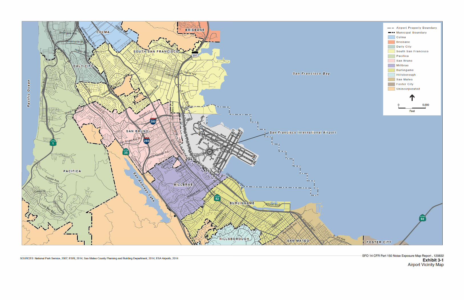
3.1 Existing Airport Facilities SFO is located approximately 13 miles south of downtown San Francisco in unincorporated San Mateo County and the active operations area is bordered by the San Francisco Bay to the east, Interstate 380 (I-380) to the north, and U.S. 101 to the west and south. Of the 5,100 acres that comprise Airport property, approximately 2,110 acres are located on land east of U.S. 101, 180 acres are not actively used for Airport operations and are located west of U.S. 101, and 2,810 acres are San Francisco Bay tidal waters. As shown on Exhibit 3-1, the Airport is surrounded by the cities of Millbrae and Burlingame (to the south), San Bruno (to the west), and South San Francisco (to the north). Other jurisdictions in the vicinity of SFO include: the City of Brisbane, the Town of Colma, Daly City, the City of Pacifica, the Town of Hillsborough, the City of San Mateo, Foster City, and San Mateo County (i.e., unincorporated areas).
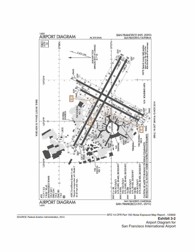
Direct access to the terminal buildings and parking facilities is provided by ramps directly from U.S. 101. Other landside facilities at SFO are accessible from North Access Road (via U.S. 101 and I-380 ramps) and San Bruno Avenue (via U.S. 101 ramps). Existing facilities at SFO are presented on Exhibit 3-2 and summarized in the following sections.
3.1.1 Airfield Facilities Airport Runways There are four runways at SFO: Runway 10L-28R is 11,870 feet long and 200 feet wide; Runway 10R-28L is 11,381 feet long and 200 feet wide; Runway 1L-19R is 7,650 feet long and 200 feet wide; and Runway 1R-19L is 8,650 feet long and 200 feet wide. Runway data are summarized in Table 3-1.
Taxiways A system of taxiways and taxilanes at SFO is designed to connect the four runways to the passenger terminal complex, air cargo aprons, fixed based operators (FBOs), and general aviation facilities. Each of the four runways has a full-length taxiway. Runways 28R and 19L have angled taxiways to expedite aircraft exiting the runways after landing.

3. Existing and Future Airport and Environs Conditions
San Francisco International Airport 3-2 ESA / 120832 14 CFR Part 150 Noise Exposure Map Report August 2015
TABLE 3-1 EXISTING (2014) RUNWAY CHARACTERISTICS, SAN FRANCISCO INTERNATIONAL AIRPORT
Runway 10L-28R Runway 10R-28L Runway 1R-19L Runway 1L-19R
Runway Characteristics 10L 28R 10R 28L 1R 19L 1L 19R
Runway Length 11,870 11,870 11,381 11,381 8,650 8,650 7,650 7,650
Runway Width 200 200 200 200 200 200 200 200
Displaced Arrival Threshold 0 300 0 300 560 0 640 0
Runway Landing Distance Available 11,193 11,570 10,704 10,681 8,090 8,650 7,010 7,650
Approach Surface Slope 34:1 50:1 34:1 50:1 20:1 50:1 20:1 34:1
Runway End Elevation (Feet above MSL) 5.6 13 7.2 12.7 11.2 9.9 10.5 8.6
Runway Markings Precision Precision Precision Precision Precision Precision Non-Precision Non-Precision
Runway Lighting HIRL, CL, PAPI HIRL, CL, TDZ, PAPI
HIRL, CL, PAPI HIRL, CL, PAPI
HIRL, CL HIRL, CL, TDZ, PAPI HIRL, CL HIRL, CL, PAPI
Part 77 Runway Category and Navigational Aids
Non-Precision RNAV(GPS)
Precision ILS CAT IIIC
Non-Precision RNAV(GPS)
Precision ILS CAT II
(SA)
Visual Precision ILS CAT I
Visual Non-precision RNAV(GPS)
Runway Approach Lighting REIL ALSF2 No MALSR REIL MALSF REIL No
NOTES: Phase 1 of the Runway Safety Area (RSA) Project, which included enhancements to Runways 10R-28L and 10L-28R, was completed in 2013. Runway safety area improvements to Runways 1R and 1L were completed in 2014. Runway data presented in this table were used to develop the 2014 Noise Exposure Map. MSL = Mean Sea Level HIRL = High Intensity Runway Lighting; CL= Centerline Lighting PAPI = Precision Approach Path Indicator; TDZ = Touchdown Zone lighting REIL = Runway End Identifier Lights; ALSF2 = Approach Lighting System with Sequenced Flashing Lights MALSR = Medium Intensity Approach Light System with Runway Alignment Indicator Lights; MALSF = Medium Intensity Approach Light System with Sequenced Flashers ILS CAT = Instrument Landing System Category; RNAV(GPS) = Area Navigation Approach ILS CAT II (SA) = Instrument Landing System Category II, Special Authorization SOURCES: Airnav.com accessed June 21, 2014; Ricondo & Associates, Inc. Airport Layout Plan, Data Sheet, San Francisco International Airport. January 17, 2014. [III-1]
3. Existing and Future Airport and Environs Conditions
San Francisco International Airport 3-4 ESA / 120832 14 CFR Part 150 Noise Exposure Map Report August 2015
This page intentionally left blank
3. Existing and Future Airport and Environs Conditions
San Francisco International Airport 3-6 ESA / 120832 14 CFR Part 150 Noise Exposure Map Report August 2015
3.1.2 Passenger Terminal Facilities The SFO terminal complex is located on the east side of the Airport, and has a series of seven boarding areas, Boarding Areas A through G, that are divided into three domestic terminals and one international terminal.
3.1.3 Airport Traffic Control Tower The Airport is serviced by an active FAA airport traffic control tower (ATCT) located in the vicinity of Terminal 2. The ATCT operates 24 hours a day, 365 days a year. Radar approach and departure control is operated by the Northern California Terminal Radar Approach Control (NORCAL TRACON) located in Mather, California.
3.1.4 Other Facilities
General Aviation Facilities General aviation includes all facets of aviation excluding military, air cargo, and scheduled passenger service. Some of the major categories of general aviation include corporate operations, air taxi operations, flight training, and traffic monitoring. The single FBO at SFO is located north of the end of Runway 10L, and is operated by Signature Flight Support. The facility offers services to general aviation aircraft including: aviation fuel, terminal and lounge, aircraft parking, maintenance hangers, and pilot services.
Air Cargo Facilities Air cargo and maintenance facilities at SFO are located on the north side of the Airport along North McDonnell Road. United Airlines and the United State Parcel Service have facilities north of the terminal complex. FedEx Express also uses apron and sorting facilities on the north side of the Airport.
Other Aviation-related facilities A number of aviation-related support facilities are located on airport property. These facilities include:
• Aircraft Rescue and Firefighting Facility (ARFF)
• Aircraft Fueling Facilities
• Airport Ground Service Maintenance Facility
• Rental Car Facilities
• Customs and Border Protection
• Airport Police
3. Existing and Future Airport and Environs Conditions
San Francisco International Airport 3-7 ESA / 120832 14 CFR Part 150 Noise Exposure Map Report August 2015
3.2 Future/Planned Airport Facilities The Airport Commission is currently constructing a new ATCT at SFO and the Runway Safety Area (RSA) Project is nearing completion. Other planned improvements at SFO that will be constructed prior to 2019 include: (1) an on-Airport hotel; (2) Terminal 3 Modernization; (3) Terminal 1 Redevelopment; (4) South Field Buildings Demolition; and (5) Long Term Parking Garage Development. The airport layout plan that was conditionally approved by the FAA in June 2014 is shown on Exhibit 3-3.
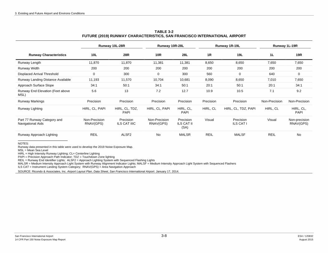
None of these projects is anticipated to have an impact on aircraft operations (i.e., number and type of aircraft) at SFO. Future runway characteristics data for SFO are provided in Table 3-2.
3.3 Navigational Aids SFO employs several navigational aids, airport lighting, and airport markings to help users of the Airport safely navigate around the Airport and SFO airspace. The navigational aids include: Instrument Landing Systems (ILS), Localizer Type Directional Aid (LDA), Area Navigation (RNAV)/Global Positioning Systems (GPS), and a VOR/DME which is the combination of a Very High Frequency (VHF) Omni-Directional Range (VOR) and Distance Measuring Equipment (DME). A glossary of terms is provided in Chapter 6 of this report.
The Localizer Type Directional Aid is of comparable use and accuracy to a localizer but is not part of a complete ILS. An LDA approach is not aligned with the runway for either operational or other reason such as terrain. The LDA approach allows the approach course to be offset so that there is enough spacing for approach to both parallel runways to be conducted at the same time when visibility permits.1 Straight-in minimums may be published where alignment does not exceed 30 degrees between the course and runway.
The GPS uses a network of satellites that create reference points to enable aircraft equipped with GPS receivers to determine their latitude, longitude, and altitude. GPS systems can be used by aircraft during all phases of flight.
Area Navigation or RNAV is a method of navigation that permits aircraft operation on any desired flight path using the combination of both GPS and ground-based navigational aids. RNAV routes and terminal procedures, including departure procedures and standard terminal arrivals, are designed with RNAV systems in mind to save time and fuel, reduce aircraft dependence on air traffic control (ATC) vectoring, and provide for more efficient use of the
1 Runways at SFO are spaced 750 feet measured from runway centerline to parallel runway centerline, which is
insufficient for the critical design aircraft to conduct simultaneous operations utilizing the runways during inclement weather conditions.
3. Existing and Future Airport and Environs Conditions
San Francisco International Airport 3-8 ESA / 120832 14 CFR Part 150 Noise Exposure Map Report August 2015
TABLE 3-2 FUTURE (2019) RUNWAY CHARACTERISTICS, SAN FRANCISCO INTERNATIONAL AIRPORT
Runway 10L-28R Runway 10R-28L Runway 1R-19L Runway 1L-19R
Runway Characteristics 10L 28R 10R 28L 1R 19L 1L 19R
Runway Length 11,870 11,870 11,381 11,381 8,650 8,650 7,650 7,650
Runway Width 200 200 200 200 200 200 200 200
Displaced Arrival Threshold 0 300 0 300 560 0 640 0
Runway Landing Distance Available 11,193 11,570 10,704 10,681 8,090 8,650 7,010 7,650
Approach Surface Slope 34:1 50:1 34:1 50:1 20:1 50:1 20:1 34:1
Runway End Elevation (Feet above MSL)
5.6 13 7.2 12.7 10.9 10.5 7.1 9.2
Runway Markings Precision Precision Precision Precision Precision Precision Non-Precision Non-Precision
Runway Lighting HIRL, CL, PAPI HIRL, CL, TDZ, PAPI
HIRL, CL, PAPI HIRL, CL, PAPI
HIRL, CL HIRL, CL, TDZ, PAPI HIRL, CL HIRL, CL, PAPI
Part 77 Runway Category and Navigational Aids
Non-Precision RNAV(GPS)
Precision ILS CAT IIIC
Non-Precision RNAV(GPS)
Precision ILS CAT II
(SA)
Visual Precision ILS CAT I
Visual Non-precision RNAV(GPS)
Runway Approach Lighting REIL ALSF2 No MALSR REIL MALSF REIL No
NOTES: Runway data presented in this table were used to develop the 2019 Noise Exposure Map. MSL = Mean Sea Level HIRL = High Intensity Runway Lighting; CL= Centerline Lighting PAPI = Precision Approach Path Indicator; TDZ = Touchdown Zone lighting REIL = Runway End Identifier Lights; ALSF2 = Approach Lighting System with Sequenced Flashing Lights MALSR = Medium Intensity Approach Light System with Runway Alignment Indicator Lights; MALSF = Medium Intensity Approach Light System with Sequenced Flashers ILS CAT = Instrument Landing System Category; RNAV(GPS) = Area Navigation Approach SOURCE: Ricondo & Associates, Inc. Airport Layout Plan, Data Sheet, San Francisco International Airport. January 17, 2014.

3. Existing and Future Airport and Environs Conditions
San Francisco International Airport 3-10 ESA / 120832 14 CFR Part 150 Noise Exposure Map Report August 2015
This page intentionally left blank
3. Existing and Future Airport and Environs Conditions
San Francisco International Airport 3-11 ESA / 120832 14 CFR Part 150 Noise Exposure Map Report August 2015
airspace. A VOR/DME is a facility consisting of two components, VOR and DME. This navigational aid works for civilian aircraft by using a VHF radio to project straight line courses (radials) from the station in all directions that pilots can use to navigate to and from the VOR/DME stations. VOR/DMEs also have distance capability that lets the pilot know their slant range distance from the station usually shown in the aircraft in nautical miles from the station. SFO has a VOR/DME located at the center of the airfield complex that is operated by the FAA. The VOR/DME at SFO is considered a Class ‘L’ VOR/DME, which has a standard service volume limit of 40 nautical miles2 (nm) between 1,000 feet and 18,000 feet. The SFO VOR/DME is used to perform a single instrument approach, and is utilized by aircraft executing missed approach procedures, or aircraft on Departures Procedures or Standard Terminal Arrivals.
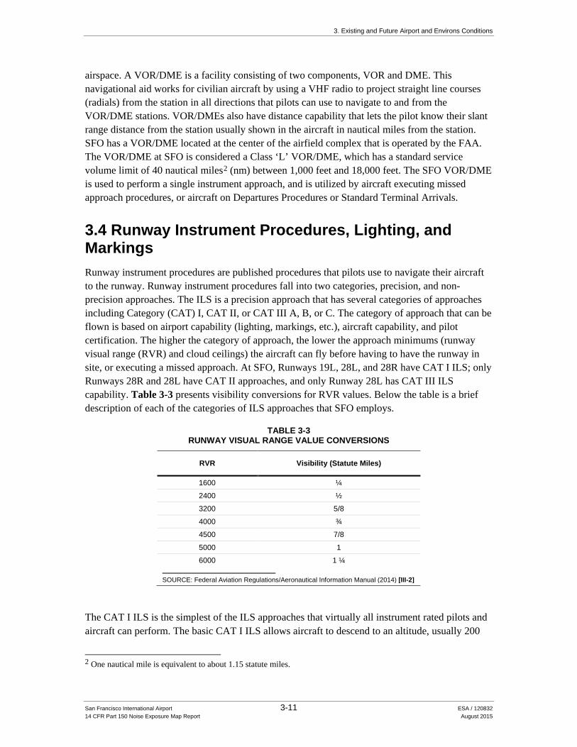
3.4 Runway Instrument Procedures, Lighting, and Markings Runway instrument procedures are published procedures that pilots use to navigate their aircraft to the runway. Runway instrument procedures fall into two categories, precision, and non-precision approaches. The ILS is a precision approach that has several categories of approaches including Category (CAT) I, CAT II, or CAT III A, B, or C. The category of approach that can be flown is based on airport capability (lighting, markings, etc.), aircraft capability, and pilot certification. The higher the category of approach, the lower the approach minimums (runway visual range (RVR) and cloud ceilings) the aircraft can fly before having to have the runway in site, or executing a missed approach. At SFO, Runways 19L, 28L, and 28R have CAT I ILS; only Runways 28R and 28L have CAT II approaches, and only Runway 28L has CAT III ILS capability. Table 3-3 presents visibility conversions for RVR values. Below the table is a brief description of each of the categories of ILS approaches that SFO employs.
TABLE 3-3 RUNWAY VISUAL RANGE VALUE CONVERSIONS
RVR Visibility (Statute Miles)
1600 ¼
2400 ½
3200 5/8
4000 ¾
4500 7/8
5000 1
6000 1 ¼
SOURCE: Federal Aviation Regulations/Aeronautical Information Manual (2014) [III-2]
The CAT I ILS is the simplest of the ILS approaches that virtually all instrument rated pilots and aircraft can perform. The basic CAT I ILS allows aircraft to descend to an altitude, usually 200
2 One nautical mile is equivalent to about 1.15 statute miles.
3. Existing and Future Airport and Environs Conditions
San Francisco International Airport 3-12 ESA / 120832 14 CFR Part 150 Noise Exposure Map Report August 2015
feet above runway altitude, and usually requires a visibility of 2400 RVR or ½ statute miles. Some CAT I ILS will have lower visibility requirements such as 1800 RVR or 3/8 of a statute mile, or could have increased visibility requirements such as 1 statute mile depending on runway approach lighting, runway length, terrain, etc.
A CAT II ILS allows aircraft to fly the instrument approach to lower minimums than the CAT I ILS. Special aircraft and pilot certifications are required prior to executing a CAT II ILS approach. Generally, CAT II ILS approach minimums allow aircraft to descend to 100 feet above airport elevation, and have a visibility requirement of 1200 RVR at most airports.
A CAT III ILS allows aircraft to fly to the lowest visibility requirements of which there is no cloud ceiling requirement. There are three categories of CAT III ILS’: CAT IIIA, CAT IIIB, and CAT IIIC. The ability to perform these categories of approaches is based on pilot and aircraft certification, as well as specific runway capability (approach lighting, runway lighting, etc.).The CAT IIIA ILS approach allows aircraft to execute the approach to 700 RVR at SFO. The CAT IIIB ILS approach allows aircraft to execute the approach down to 600 RVR at SFO. Lastly, the CAT IIIC ILS approach has no visibility requirement allowing aircraft to execute the approach down to nil visibility conditions. Aircraft capable of performing this CAT III approaches are able to autoland and track the runway centerline throughout the landing and rollout via the autopilot.
Non-Precision approaches including RNAV (GPS), VOR, and LDA have higher approach minimums than ILS approaches due to their lower level of precision. Pilots utilize these non-precision approaches to SFO’s runways when weather conditions permit.
Another type of approach procedure that SFO employs to increase runway capacity ties in with the ILS, RNAV, and LDA approaches, and is what is called a Precision Runway Monitoring (PRM) approach. Since both parallel runways are only separated by 750 feet centerline to centerline, simultaneous instrument approaches are not authorized, and staggering aircraft would require two nautical mile separation. The PRM coupled along with its approach allows controllers to void the separation minimums, but employs a no transgression zone (NTZ) where if an aircraft penetrates the NTZ, the air traffic controller will issue a ‘breakout’ maneuver clearance to the at risk aircraft, and a go-around will be initiated. During these approaches, aircraft communicate on tower frequency, but monitor a second tower frequency that monitors the NTZ, and gives ‘breakout’ clearances if necessary.
3.4.1 Runway 10L Runway 10L is 11,870 feet long by 200 feet wide, has precision approach markings and is in good condition. Runway 10L is served by a RNAV (GPS) approach that provides approach minima of 1,200 foot ceilings above the runway threshold, and one and a quarter statute mile (SM) visibility. Runway 10L has high intensity runway lighting (HIRL), and centerline lighting (CL). A 3.0° precision approach path indicator (PAPI) is located on the left side of the approach end of the runway for aircraft navigating to the runway visually.
3. Existing and Future Airport and Environs Conditions
San Francisco International Airport 3-13 ESA / 120832 14 CFR Part 150 Noise Exposure Map Report August 2015
3.4.2 Runway 28R Runway 28R is 11,870 feet long by 200 feet wide, has precision approach markings and is in good condition. Runway 28R has a 300 foot displaced threshold reducing the landing distance available to 11,570 feet. Runway 28R is served by a CAT IIIC ILS approach that provides approach minima down to nil weather conditions. There are also a non-precision approaches to Runway 28R that include: RNAV (GPS), RNAV (GPS) PRM, LDA/DME, and a LDA PRM instrument approach. When weather conditions permit, Runway 28R has two visual approach procedures, the Quiet Bridge and the Tip Toe visual approaches. Runway 28R has HIRL, CL, and touchdown zone lighting, as well as an Approach Lighting System with Sequenced Flashing Lights (ALSF2). A 3.0° PAPI is located on the left side of the approach end of the runway for aircraft navigating to the runway visually.
3.4.3 Runway 10R Runway 10R is 11,381 feet long by 200 feet wide, has precision approach markings and is in good condition. Runway 10R is served by a RNAV (GPS) approach that provides approach minima of 1,200 foot ceilings above the runway threshold, and one and a quarter statute mile (SM) visibility. However, if aircraft are equipped with RNP, approach minimums are reduced to 400 feet and one and a quarter SM visibility. Runway 10R has high intensity runway lighting (HIRL), and CL. A 3.0° PAPI is located on the left side of the approach end of the runway for aircraft navigating to the runway visually.
3.4.4 Runway 28L Runway 28L is 11,381 feet long by 200 feet wide, has precision approach markings and is in good condition. Runway 28L has a 300 foot displaced threshold, which with declared distances, reduces the landing distance available to 10,681 feet. Runway 28L is served by a Special Authorization (SA) CAT II ILS approach that provides approach minima down to 100 feet above the runway threshold. The SA means that the pilots need specific training before shooting the approach. There are also non-precision approaches to Runway 28L that include an RNAV (GPS), and an RNAV (GPS) PRM approaches. When weather conditions permit, Runway 28L has two visual approach procedures, the Quiet Bridge and the Tip Toe visual approaches. Runway 28L has HIRL, CL, as well as a Medium Intensity Approach Light System with Runway Alignment Indicator Lights (MALSR). A 3.0° PAPI is located on the left side of the approach end of the runway for aircraft navigating to the runway visually.
3.4.5 Runway 1R Runway 1R is 8,650 feet long by 200 feet wide, has precision approach markings and is in good condition. Runway 1R has a displaced threshold of 560 feet. Runway 1R does not have any instrument approach procedures, however, it does have HIRL and CL.
3. Existing and Future Airport and Environs Conditions
San Francisco International Airport 3-14 ESA / 120832 14 CFR Part 150 Noise Exposure Map Report August 2015
3.4.6 Runway 19L Runway 19L is 8,646 feet long by 200 feet wide, has precision approach markings and is in good condition. Runway 19L is served by a CAT I ILS approach that provides approach minima down to 300 foot ceilings, and one SM visibility. There are also a non-precision approaches to Runway 19L that include an RNAV (GPS), and a VOR approach. Runway 19L has HIRL, CL, and touchdown zone lighting, as well as a Medium Intensity Approach Light System with Sequenced Flashers (MALSF). A 3.0° PAPI is located on the left side of the approach end of the runway for aircraft navigating to the runway visually.
3.4.7 Runway 1L Runway 1L is 7,650 feet long by 200 feet wide, has non-precision approach markings and is in good condition. Runway 1L has a displaced threshold of 640 feet. Runway 1L does not have any instrument approach procedures, however, it does have HIRL and CL.
3.4.8 Runway 19R Runway 19R is 7,650 feet long by 200 feet wide, has non-precision approach markings and is in good condition. Runway 19R is served by a RNAV (GPS) approach that provides approach minima down to 400 foot ceilings, and one and a quarter SM visibility. Runway 19R has HIRL, CL, as well as a 3.0° PAPI that is located on the left side of the approach end of the runway for aircraft navigating to the runway visually.
3.5 Runway Assignments and Operational Flows There are four primary operational flows/configurations at SFO:
• 28/1 Operations: During this flow configuration Runways 28L and 28R are the primary arrival runways and Runways 1L and 1R are the primary departure runways. Runways 28L and 28R are secondary departure runways in this configuration and are typically used by heavy aircraft (cargo and passenger), particularly those headed to international destinations.
• 28/28 Operations: During this flow configuration Runways 28L and 28R are used for arrivals and departures. This flow configuration is used approximately 9% of the year, typically when there are strong westerly winds and during San Francisco’s Annual Fleet Week Air Show in October.
• 10/19 Operations: Typically referred to as reverse-flow operations. During this flow configuration Runways 19L and 19R are used for arrivals and Runways 10L and 10R are used for departures. This flow configuration is used less than 5 percent of the year and only under certain weather/wind conditions.
• 10/10 Operations: During this flow configuration arrivals and departures are assigned to Runways 10L and 10R. This flow configuration is used less than 5 percent of the year and only under certain weather/wind conditions.
3. Existing and Future Airport and Environs Conditions
San Francisco International Airport 3-15 ESA / 120832 14 CFR Part 150 Noise Exposure Map Report August 2015
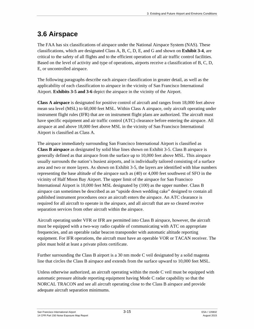
3.6 Airspace The FAA has six classifications of airspace under the National Airspace System (NAS). These classifications, which are designated Class A, B, C, D, E, and G and shown on Exhibit 3-4, are critical to the safety of all flights and to the efficient operation of all air traffic control facilities. Based on the level of activity and type of operations, airports receive a classification of B, C, D, E, or uncontrolled airspace.
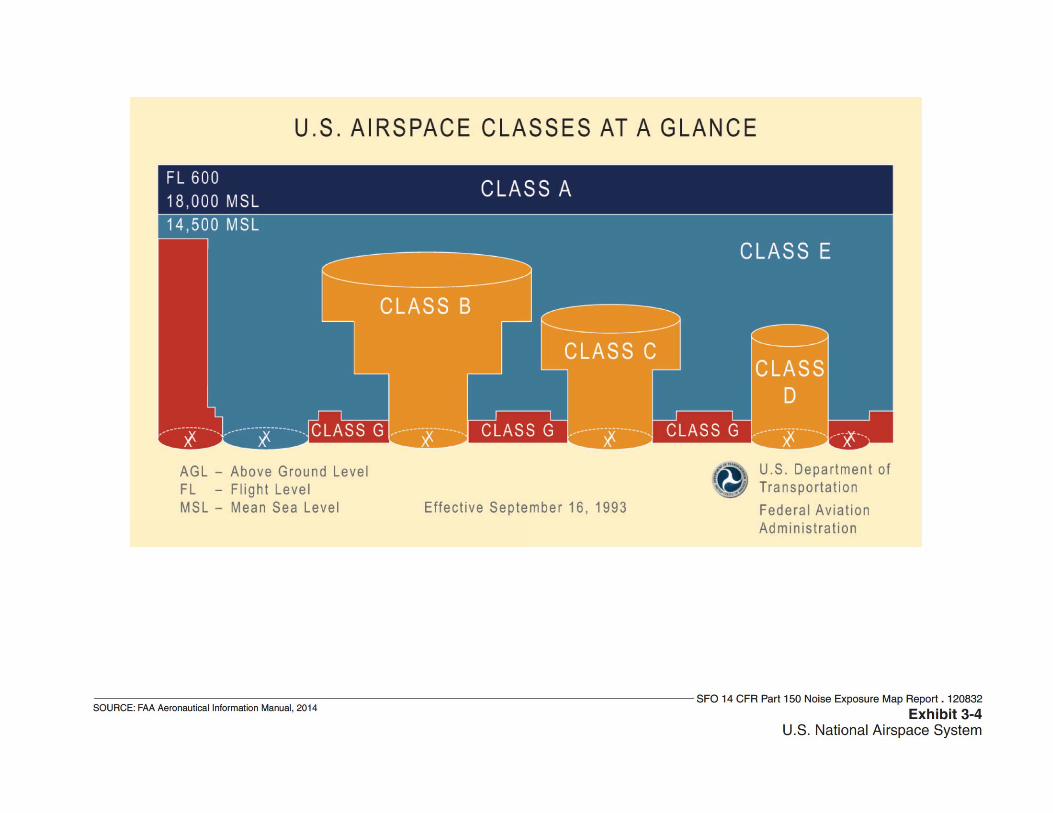
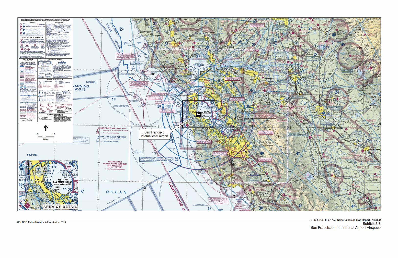
The following paragraphs describe each airspace classification in greater detail, as well as the applicability of each classification to airspace in the vicinity of San Francisco International Airport. Exhibits 3-5 and 3-6 depict the airspace in the vicinity of the Airport.
Class A airspace is designated for positive control of aircraft and ranges from 18,000 feet above mean sea level (MSL) to 60,000 feet MSL. Within Class A airspace, only aircraft operating under instrument flight rules (IFR) that are on instrument flight plans are authorized. The aircraft must have specific equipment and air traffic control (ATC) clearance before entering the airspace. All airspace at and above 18,000 feet above MSL in the vicinity of San Francisco International Airport is classified as Class A.
The airspace immediately surrounding San Francisco International Airport is classified as Class B airspace as designated by solid blue lines shown on Exhibit 3-5. Class B airspace is generally defined as that airspace from the surface up to 10,000 feet above MSL. This airspace usually surrounds the nation’s busiest airports, and is individually tailored consisting of a surface area and two or more layers. As shown on Exhibit 3-5, the layers are identified with blue numbers representing the base altitude of the airspace such as (40) or 4,000 feet southwest of SFO in the vicinity of Half Moon Bay Airport. The upper limit of the airspace for San Francisco International Airport is 10,000 feet MSL designated by (100) as the upper number. Class B airspace can sometimes be described as an “upside down wedding cake” designed to contain all published instrument procedures once an aircraft enters the airspace. An ATC clearance is required for all aircraft to operate in the airspace, and all aircraft that are so cleared receive separation services from other aircraft within the airspace.
Aircraft operating under VFR or IFR are permitted into Class B airspace, however, the aircraft must be equipped with a two-way radio capable of communicating with ATC on appropriate frequencies, and an operable radar beacon transponder with automatic altitude reporting equipment. For IFR operations, the aircraft must have an operable VOR or TACAN receiver. The pilot must hold at least a private pilots certificate.
Further surrounding the Class B airport is a 30 nm mode C veil designated by a solid magenta line that circles the Class B airspace and extends from the surface upward to 10,000 feet MSL.
Unless otherwise authorized, an aircraft operating within the mode C veil must be equipped with automatic pressure altitude reporting equipment having Mode C radar capability so that the NORCAL TRACON and see all aircraft operating close to the Class B airspace and provide adequate aircraft separation minimums.

3. Existing and Future Airport and Environs Conditions
San Francisco International Airport 3-18 ESA / 120832 14 CFR Part 150 Noise Exposure Map Report August 2015
This page intentionally left blank
3. Existing and Future Airport and Environs Conditions
San Francisco International Airport 3-20 ESA / 120832 14 CFR Part 150 Noise Exposure Map Report August 2015
As shown on Exhibits 3-5 and 3-6, the airspace in the San Francisco Bay Area region is highly congested with many airports, both commercial service and general aviation. These airports and airspaces that lie beneath, abeam, or above the SFO Class B airspace include Class C, D, and E airspace.
Class C airspace is the airspace from the surface up to 4,000 feet above the airport elevation charted in MSL surrounding those airports that have an operational control tower, are serviced by a radar approach control, and that have a certain number of IFR operations or passenger enplanements. Class C airspace is represented by solid magenta lines on Exhibit 3-5, examples of which include Metropolitan Oakland International Airport (OAK) and Norman Y. Mineta San Jose International Airport (SJC). Like Class B airspace, Class C airspace is individually tailored to meet the needs of the respective airport. The airspace usually consists of a surface area with a 5-nm radius from the surface up to 4,000 feet above the airport elevation, and a 10-nm radius that extends from 1,200 feet to 4,000 above the airport elevation. An example of where the Class C airspace is individually tailored is OAK’s Class C airspace of which lies entirely beneath the SFO Class B airspace. The extent of OAK’s 5-nm radius is shown from the surface (SFC) to the terminal airspace that lies above (T), or up to, but not including 2,100 feet MSL (21). The same is true for the outer surfaces of the OAK Class C airspace. Pilots must establish two-way radio communications with the ATC facility providing air traffic control services prior to entering the airspace. VFR aircraft are separated from IFR aircraft in Class C airspace.
Class D airspace is generally that airspace from the surface to 2,500 feet AGL. The configuration of Class D airspace areas are individually tailored and shown as a dashed blue line with an altitude representing the extent of the airspace from the surface. When instrument procedures are published, the airspace will normally be designed to contain the procedures with either Class D or E airspace. Class D airspace only surround airports that have an operational control tower of which pilots are required to establish and maintain two-way radio communication with the ATC facility. Examples of Class D airspace throughout the San Francisco area include Hayward Executive (HWD), San Carlos (SQL), Palo Alto (PAO), and Moffett Federal (NUQ) airports. Due to airspace constraints, each of these airport have tailored Class D airspace. For example, PAO’s and NUQ’s airspace abut each other as shown as a dashed blue circle and extends from the surface up to, but not including 1,500 feet AGL under the SJC Class C airspace, but up to 2,000 feet AGL when outside the SJC airspace for PAO; and up to, but not including 2,500 feet AGL for NUQ’s Class D airspace.
Class E airspace is generally that controlled airspace that is not Class A, B, C, or D airspace. Class E airspace extends upward from either the surface or designated altitude to the overlying or adjacent controlled airspace. Also in this class are Victor airways, airspace beginning at either 700 feet or 1,200 feet AGL used to transition to/from the terminal or en route environments, and offshore airspace areas designated below 18,000 feet MSL. Unless designated at a lower altitude, Class E airspace begins at 14,500 feet MSL over the United States, including that airspace overlying the water within 12 nm off the coast of the 48 contiguous states and Alaska. It does not include airspace at or above 18,000 feet MSL. Class E airspace ensures that IFR aircraft remain in
3. Existing and Future Airport and Environs Conditions
San Francisco International Airport 3-21 ESA / 120832 14 CFR Part 150 Noise Exposure Map Report August 2015
controlled airspace when approaching airports without Class D airspace or when flying on Victor airways that are below 18,000 feet MSL.
Most of the country has a Class E airspace limit of 1,200 feet AGL. Where it decreases to 700 feet AGL is depicted by a shaded magenta line. The floor of Class E airspace near SFO is 700 feet AGL as depicted along the Pacific Ocean coast line, west of SFO. The more defined side of the magenta line indicates areas where the floor of Class E airspace rises to 1,200 feet AGL. When Class E extends down to the surface, it is depicted by a dashed magenta line usually off-shooting a Class C airport such as OAK.
When the lower level of Class E airspace is not depicted, the airspace is considered uncontrolled or Class G airspace. Class G airspace begins at ground level and in very remote areas, it has an upper limit of up to but not including 14,500 feet MSL. The top of Class G airspace is usually where Class E airspace begins, usually either 700 foot AGL depicted by magenta shading, or 1,200 foot AGL areas depicted by blue shading. Class G airspace begins at the surface throughout much of the area surrounding the Class B, C, D, and E airspaces throughout the San Francisco area. Uncontrolled airports located in Class G airspace are depicted in magenta since they do not have a control tower. Half Moon Bay Airport (HAF) located southwest of SFO is within Class G airspace. While VFR aircraft can operate in Class G airspace, IFR aircraft are not permitted.
Special Use airspace consists of that airspace wherein activities must be confined because of their nature, or wherein limitations are imposed on aircraft operations that are not a part of those activities, or both. There are currently no special use airspaces within the immediate vicinity of SFO.
3.7 Air Traffic Control Air traffic control in the United States is managed by three primary types of facilities: ATCTs, Terminal Radar Approach Control (TRACON) facilities, and Air Route Traffic Control Centers (ARTCCs). A brief overview of these facilities and how they control flight to and from the Airport is provided in the following paragraphs.
The FAA San Francisco ATCT is currently located at Terminal 2; in 2015, the new ATCT (currently under construction) will be located between Terminals 1 and 2. FAA Air Traffic Control personnel provide Air Traffic Control Services to ensure the safe and efficient use of navigable airspace. They accomplish this mission by ensuring adequate separation between aircraft on the ground and in the air. From the ATCT, FAA personnel maintain air traffic control and communications with pilots operating aircraft on the runways or within the Terminal Control Area, which is the airspace in the vicinity of the Airport. Pilots of aircraft departing the Airport contact controllers in the ATCT for authorization to taxi to a particular runway and for clearance to take off. Once the aircraft is airborne, the controller will instruct the pilot to contact the NORCAL TRACON. Controllers in the TRACON are responsible for separating and sequencing arrival and departure operations to airports within the northern California area. The ARTCC is responsible for controlling aircraft across a multi-state area including California, Arizona, and Nevada. Controllers at the ARTCC provide separation services for aircraft as well as traffic
3. Existing and Future Airport and Environs Conditions
San Francisco International Airport 3-22 ESA / 120832 14 CFR Part 150 Noise Exposure Map Report August 2015
advisories. Generally, aircraft departing from or arriving at the Airport are transitioned to and from ARTCC control near the boundary of the TRACON airspace at designated arrival and departure “gates”. Most aircraft enter or exit the San Francisco area via one of the numerous federal (i.e., Victor) airways. Aircraft above 18,000 feet MSL use the Jet Route System which in the SFO area is controlled by the Oakland ARTCC, or Oakland Center.
3.8 Standard Terminal Arrivals and Departure Procedures The San Francisco Bay Area airspace is structured so that arriving aircraft can be safely and efficiently transitioned from the en route environment to the approach control environment and from the approach control environment to the airfield proper; these structures are known as Standard Terminal Arrivals (STARs). Likewise, the airspace is structured so that departing aircraft can transition from airfield to the terminal environment and ultimately to the en route environment; these structures are known as Departure Procedures (DPs). As discussed previously, aircraft flying in and out of SFO follow these precise routes depending on the operational flow of the Airport. STARs and DPs are a combination of lateral, vertical, and speed commands along a set of fixes (intersections) or waypoints that are typically pre-programmed into the aircraft’s flight management system (FMS), and executed upon ATC clearance. As the FAA continues to revamp the national airspace system and its procedures within, as part of NextGen and the metroplex system, newer RNAV (GPS) arrival and departure procedures are being created to provide benefits to both ATC and pilots by reducing communications, reducing flight time and distance, lowering fuel burn due to more efficient flight profiles, and increasing predictability.
When flying a STAR or DP, the pilot will follow waypoints or fixes that are either ground based or RNAV (GPS) based depending on aircraft capability. In conventional procedures, fixes are defined by the location of a navigational aid (e.g. VORTACs and VORs) or determined by reference to these navigational aids such as DME intersections. The advantage of the RNAV STARs and DPs are that waypoints are defined by longitude and latitude, and allow aircraft to fly a more direct course from point to point instead of from navigational aid to navigational aid. STARs and DPs may serve more than one airport in an area, and a single airport may have multiple STARs and DPs such as SFO. Each of the published procedures lateral navigation are referenced in the following sections. The STARs and DPs described in the following sections were in effect in June 2014 prior to the initiation of Phase 2 of the SFO RSA Project which required the temporary closure of Runways 1R-19L and 1L-19R. Both runways re-opened in September 2014.
3.8.1 Standard Terminal Arrivals As shown in Table 3-4, aircraft are routed to SFO from all directions via mostly conventional arrival procedures and one RNAV arrival from the east. This is because most aircraft arriving from over the Pacific Ocean will arrive from the north due to great circle routing. The following is a description of each arrival procedure by direction.

3. Existing and Future Airport and Environs Conditions
San Francisco International Airport 3-23 ESA / 120832 14 CFR Part 150 Noise Exposure Map Report August 2015
TABLE 3-4
STANDARD TERMINAL ARRIVAL ROUTES, SAN FRANCISCO INTERNATIONAL AIRPORT
Procedure Name Procedure Type Arrival Direction
BIG SUR TWO Arrival Conventional South
GOLDEN GATE SIX Arrival Conventional North
HADLY TWO Arrival Conventional South
LOCKE ONE Arrival Conventional East
MODESTO FIVE Arrival Conventional East
POINT REYES ONE Arrival Conventional North
RISIT FOUR Arrival Conventional Northeast
STINS TWO Arrival Conventional North
YOSEM TWO Arrival RNAV East
NOTE: RNAV = Area Navigation SOURCE: AirNav.com, June 2014.
North GOLDEN GATE SIX Arrival – This arrival procedure is a turbojet only arrival that has multiple arrival VOR entry points from the north including the Rosenburg VOR, Fortuna VOR, Red Bluff VOR, and the Mustang VOR. From these VORs, aircraft are routed south along the California Pacific Coast to the Point Reyes VOR located 36 nm northwest of SFO, and then directed to the SFO VOR. Aircraft landing at SFO cross the LOZIT intersection located 14 nm southeast of the Point Reyes VOR at 11,000 feet MSL.
POINT REYES ONE Arrival – Like the Golden Gate Six Arrival, this procedure routes aircraft to the Point Reyes VOR, and then south 43 south to the HADLY intersection. From this point aircraft are routed east to the Woodside VOR before being radar vectored back north toward SFO.
RISTI FOUR Arrival – This conventional arrival procedure from the northeast where aircraft are either routed from the Sacramento or Manteca VOR to the MOVDD intersection located approximately 44 nm east of SFO. From the MOVDD intersection, aircraft are routed to the southwest toward SFO to the CEDES intersection located 36 nm from SFO. From this intersection, aircraft are radar vectored onto the final approach course.
STINS TWO Arrival – This conventional arrival procedure has multiple arrival VOR entry points from the north including the Williams VOR, Mustang VOR, Red Bluff VOR, Roseburg VOR, Fortuna VOR, Mendocino VOR, Santa Rosa VOR, all which route aircraft south to the Point Reyes VOR located 36 nm north of SFO. At Point Reyes VOR, turbojet aircraft are expected to cross at 9,000 feet MSL, while turboprop aircraft are expected to cross at 7,000 feet MSL. After the Point Reyes VOR, aircraft are routed southeast to STINS intersection, then to the San Francisco VOR, at which point aircraft can expect radar vectors to the final approach course.
3. Existing and Future Airport and Environs Conditions
San Francisco International Airport 3-24 ESA / 120832 14 CFR Part 150 Noise Exposure Map Report August 2015
East LOCKE ONE Arrival – This arrival procedure has multiple arrival VOR entry points from the east including the Mustang VOR, Mina VOR, Coaldale VOR, and Clovis VOR. From these VORs, aircraft are routed west to the Modesto VOR located approximately 70 nm east of SFO. From the Modesto VOR, aircraft are then further routed west to the GROAN intersection, and then northwest to the LOCKE intersection where aircraft are expected to cross LOCKE at 10,000 feet (turbojets are expected to cross at 250 knots indicated airspeed (KIAS)). Aircraft are further routed northwest where they are radar vectored onto the final approach course when SFO is landing to the south.
MODESTO FIVE Arrival – This arrival has multiple arrival VOR entry points from the east including the Mustang VOR, Mina VOR, Coaldale VOR, and the Clovis VOR. From these VORs aircraft are routed west to the Modesto VOR located approximately 70 miles east of SFO. From the Modesto VOR, aircraft are then routed west to the CEDES intersection where aircraft are expected to cross CEDES at 11,000 feet. From CEDES, aircraft are routed toward the southwest of SFO, and can expect radar vectors to the final approach course when SFO is landing to the north.
YOSEM TWO Arrival – This arrival procedure is an RNAV procedure from the east in which aircraft proceed inbound from Coaldale VOR or LIDAT intersection to the YOSEM intersection. From YOSEM intersection, aircraft are routed southwest to BONNS intersection, and can expect to cross BONNS at 11,000 feet MSL and at 250 KIAS. From BONNS intersection, aircraft are routed toward the FAITH intersection, and are expected to cross at 7,000 feet MSL at 210 KIAS. From FAITH intersection, aircraft can expect radar vectors to the final approach course.
South BIG SUR TWO Arrival – This arrival is a conventional turbojet only arrival where aircraft are routed from the south from the Big Sur VOR north to the BOLDR intersection located approximately 30 nm south of the final approach courses to Runways 28L and 28R. At the BOLDR intersection, aircraft can expect to cross BOLDR at 10,000 feet MSL and at 250 KIAS. From BOLDR, aircraft will further proceed north where they will be radar vectored onto the final approach course to SFO.
HADLY TWO Arrival – This arrival is a conventional arrival that routes aircraft from the Big Sur VOR up the Pacific west coast to the EUGEN intersection located approximately 32 nm south of SFO. Turbojets can expect to cross the EUGEN intersection at 11,000 feet MSL, and all aircraft can expect to cross at 250 KIAS before being further routed north up the coast to the Sausalito VOR before being radar vectored onto the final approach course when SFO is in a south flow.
3. Existing and Future Airport and Environs Conditions
San Francisco International Airport 3-25 ESA / 120832 14 CFR Part 150 Noise Exposure Map Report August 2015
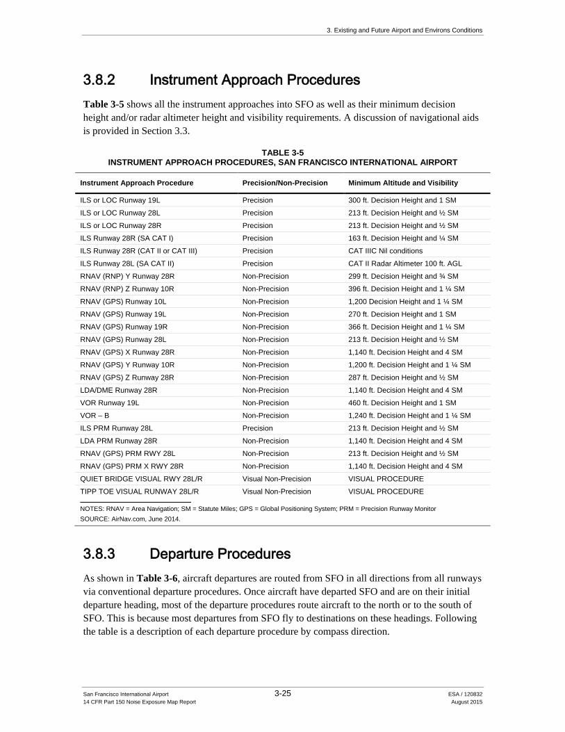
3.8.2 Instrument Approach Procedures Table 3-5 shows all the instrument approaches into SFO as well as their minimum decision height and/or radar altimeter height and visibility requirements. A discussion of navigational aids is provided in Section 3.3.
TABLE 3-5 INSTRUMENT APPROACH PROCEDURES, SAN FRANCISCO INTERNATIONAL AIRPORT
Instrument Approach Procedure Precision/Non-Precision Minimum Altitude and Visibility
ILS or LOC Runway 19L Precision 300 ft. Decision Height and 1 SM
ILS or LOC Runway 28L Precision 213 ft. Decision Height and ½ SM
ILS or LOC Runway 28R Precision 213 ft. Decision Height and ½ SM
ILS Runway 28R (SA CAT I) Precision 163 ft. Decision Height and ¼ SM
ILS Runway 28R (CAT II or CAT III) Precision CAT IIIC Nil conditions
ILS Runway 28L (SA CAT II) Precision CAT II Radar Altimeter 100 ft. AGL
RNAV (RNP) Y Runway 28R Non-Precision 299 ft. Decision Height and ¾ SM
RNAV (RNP) Z Runway 10R Non-Precision 396 ft. Decision Height and 1 ¼ SM
RNAV (GPS) Runway 10L Non-Precision 1,200 Decision Height and 1 ¼ SM
RNAV (GPS) Runway 19L Non-Precision 270 ft. Decision Height and 1 SM
RNAV (GPS) Runway 19R Non-Precision 366 ft. Decision Height and 1 ¼ SM
RNAV (GPS) Runway 28L Non-Precision 213 ft. Decision Height and ½ SM
RNAV (GPS) X Runway 28R Non-Precision 1,140 ft. Decision Height and 4 SM
RNAV (GPS) Y Runway 10R Non-Precision 1,200 ft. Decision Height and 1 ¼ SM
RNAV (GPS) Z Runway 28R Non-Precision 287 ft. Decision Height and ½ SM
LDA/DME Runway 28R Non-Precision 1,140 ft. Decision Height and 4 SM
VOR Runway 19L Non-Precision 460 ft. Decision Height and 1 SM
VOR – B Non-Precision 1,240 ft. Decision Height and 1 ¼ SM
ILS PRM Runway 28L Precision 213 ft. Decision Height and ½ SM
LDA PRM Runway 28R Non-Precision 1,140 ft. Decision Height and 4 SM
RNAV (GPS) PRM RWY 28L Non-Precision 213 ft. Decision Height and ½ SM
RNAV (GPS) PRM X RWY 28R Non-Precision 1,140 ft. Decision Height and 4 SM
QUIET BRIDGE VISUAL RWY 28L/R Visual Non-Precision VISUAL PROCEDURE
TIPP TOE VISUAL RUNWAY 28L/R Visual Non-Precision VISUAL PROCEDURE
NOTES: RNAV = Area Navigation; SM = Statute Miles; GPS = Global Positioning System; PRM = Precision Runway Monitor SOURCE: AirNav.com, June 2014.
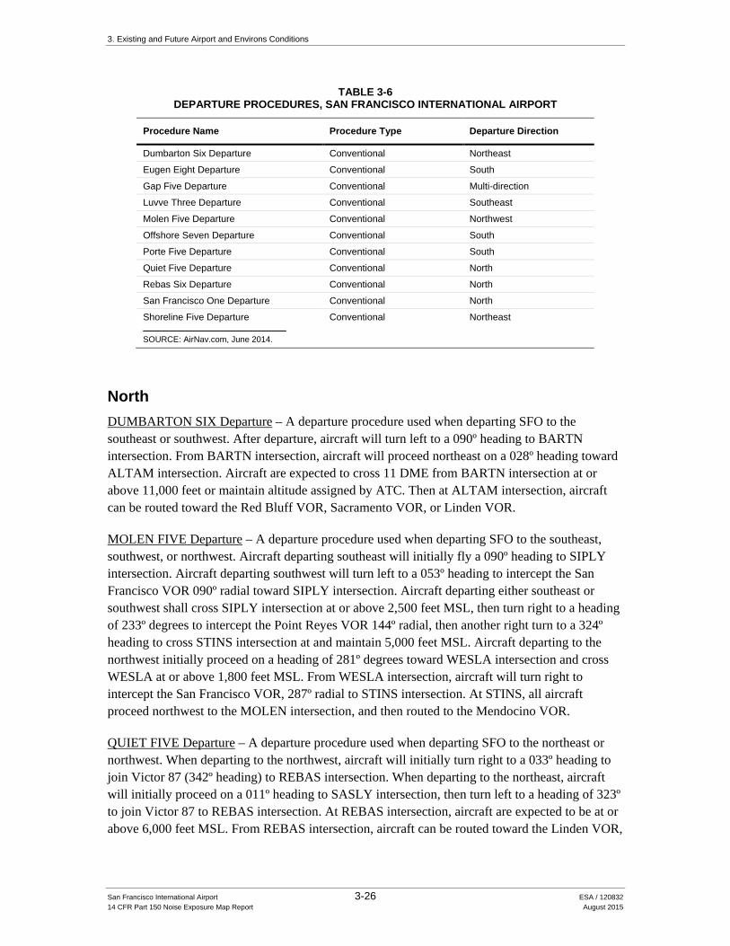
3.8.3 Departure Procedures As shown in Table 3-6, aircraft departures are routed from SFO in all directions from all runways via conventional departure procedures. Once aircraft have departed SFO and are on their initial departure heading, most of the departure procedures route aircraft to the north or to the south of SFO. This is because most departures from SFO fly to destinations on these headings. Following the table is a description of each departure procedure by compass direction.
3. Existing and Future Airport and Environs Conditions
San Francisco International Airport 3-26 ESA / 120832 14 CFR Part 150 Noise Exposure Map Report August 2015
TABLE 3-6 DEPARTURE PROCEDURES, SAN FRANCISCO INTERNATIONAL AIRPORT
Procedure Name Procedure Type Departure Direction
Dumbarton Six Departure Conventional Northeast
Eugen Eight Departure Conventional South
Gap Five Departure Conventional Multi-direction
Luvve Three Departure Conventional Southeast
Molen Five Departure Conventional Northwest
Offshore Seven Departure Conventional South
Porte Five Departure Conventional South
Quiet Five Departure Conventional North
Rebas Six Departure Conventional North
San Francisco One Departure Conventional North
Shoreline Five Departure Conventional Northeast
SOURCE: AirNav.com, June 2014.
North DUMBARTON SIX Departure – A departure procedure used when departing SFO to the southeast or southwest. After departure, aircraft will turn left to a 090º heading to BARTN intersection. From BARTN intersection, aircraft will proceed northeast on a 028º heading toward ALTAM intersection. Aircraft are expected to cross 11 DME from BARTN intersection at or above 11,000 feet or maintain altitude assigned by ATC. Then at ALTAM intersection, aircraft can be routed toward the Red Bluff VOR, Sacramento VOR, or Linden VOR.
MOLEN FIVE Departure – A departure procedure used when departing SFO to the southeast, southwest, or northwest. Aircraft departing southeast will initially fly a 090º heading to SIPLY intersection. Aircraft departing southwest will turn left to a 053º heading to intercept the San Francisco VOR 090º radial toward SIPLY intersection. Aircraft departing either southeast or southwest shall cross SIPLY intersection at or above 2,500 feet MSL, then turn right to a heading of 233º degrees to intercept the Point Reyes VOR 144º radial, then another right turn to a 324º heading to cross STINS intersection at and maintain 5,000 feet MSL. Aircraft departing to the northwest initially proceed on a heading of 281º degrees toward WESLA intersection and cross WESLA at or above 1,800 feet MSL. From WESLA intersection, aircraft will turn right to intercept the San Francisco VOR, 287º radial to STINS intersection. At STINS, all aircraft proceed northwest to the MOLEN intersection, and then routed to the Mendocino VOR.
QUIET FIVE Departure – A departure procedure used when departing SFO to the northeast or northwest. When departing to the northwest, aircraft will initially turn right to a 033º heading to join Victor 87 (342º heading) to REBAS intersection. When departing to the northeast, aircraft will initially proceed on a 011º heading to SASLY intersection, then turn left to a heading of 323º to join Victor 87 to REBAS intersection. At REBAS intersection, aircraft are expected to be at or above 6,000 feet MSL. From REBAS intersection, aircraft can be routed toward the Linden VOR,
3. Existing and Future Airport and Environs Conditions
San Francisco International Airport 3-27 ESA / 120832 14 CFR Part 150 Noise Exposure Map Report August 2015
Sacramento VOR, or continue on a heading of 342º to SASSU intersection, and then north to the Mendocino VOR. Aircraft can be routed further north on a 342º heading to the SAWNA intersection, then split off toward the Chico VOR or Red Bluff VOR.
REBAS SIX Departure – A departure procedure used when departing SFO to the northeast or northwest. When departing to the northeast, aircraft will turn left to a 333º heading and intercept the San Francisco VOR 350º radial to cross ZEPDA intersection at or above 1,800 feet MSL. After ZEPDA intersection, aircraft will turn left and intercept Victor 87 (SFO VOR, 342º radial) to cross REBAS intersection at or above 6,000 feet MSL. From REBAS, aircraft will proceed direct to the Scaggs Island VOR, and then to the Maxwell VOR. From Maxwell VOR, aircraft can be routed to either the Red Bluff VOR or Chico VOR. Aircraft departing to the northwest will initially turn right to a heading of 013º degrees to intercept Victor 87 (SFO VOR, 342º radial). Once established on Victor 87, aircraft will follow identical routing as aircraft departing to the northeast.
SAN FRANCISCO Departure – A departure procedure used when departing SFO to the northeast or northwest. Aircraft departing northeast will initially fly heading 033º degrees and cross the San Francisco VOR 6 DME Arc at or above 3,000 feet MSL, then aircraft will receive radar vectors to join assigned routing/fix. Aircraft departing northwest will initially fly a heading of 281º degrees to the NORMM intersection, and then receive radar vectors to join assigned routing/fix.
SHORELINE FIVE Departure – A departure procedure used when departing SFO to the northwest. Upon departure, aircraft turn right direct to the Oakland VOR, and are expected to cross at or above 4,000 feet MSL. From the Oakland VOR, aircraft can either join Victor 195 to the SUWAD intersection, at which they are expected to cross SUWAD at or above 8,000 ft. MSL, then direct to the SUTHU intersection, and direct to the Red Bluff VOR. Other routing consists of joining V6 direct to the SUXPY intersection. Aircraft shall cross the SUXPY intersection at or above 6,000 feet MSL, and then direct REJOY intersection, and direct to the Sacramento VOR. A final routing off of the Oakland VOR is direct to the TAHDU intersection. Aircraft shall cross the TAHDU intersection at or above 7,000 feet MSL, and then proceed direct to the SUZYE intersection, and direct to the Linden VOR.
South EUGEN EIGHT Departure – A departure procedure used when heading to destinations south of SFO. Upon departure to the northeast, aircraft turn left to a heading of 333º degrees to SEPDY intersection. Aircraft shall cross the SEPDY intersection at or above 1,900 feet MSL, then turn left to a heading of 203º degrees to intercept the Sausalito VOR 168º radial to the ZUPAX intersection. Aircraft departing SFO to the west initially fly a heading of 280º degrees to SENZY intersection. Aircraft shall cross SENZY intersection at or above 2,500 feet MSL, then turn left to intercept the Sausalito VOR 168º radial, direct to the ZUPAX intersection. Upon reaching the ZUPAX intersection, all aircraft turn left direct to the EUGEN intersection; join Victor 27 direct to the SHOEY intersection, direct to the Big Sur VOR or join Victor 27 direct to the SHOEY intersection, then join Victor 230 direct to the Salinas VOR.
3. Existing and Future Airport and Environs Conditions
San Francisco International Airport 3-28 ESA / 120832 14 CFR Part 150 Noise Exposure Map Report August 2015
GAP FIVE Departure – A departure procedure used for muti-directional departures from SFO. Aircraft departing to the northeast turn left to a heading of 350º degrees, and shall expect radar vectors to assigned routing/fix. Aircraft departing to the west/northwest fly a heading of 281º degrees direct to the NORMM intersection, then expect radar vectors to assigned routing/fix. Upon departure, aircraft departing to the southwest and southeast will turn left to intercept the San Francisco VOR, 090º radial, direct to the BARTN intersection, then a right turn to a heading of 208º degrees direct to the Woodside VOR. After the Woodside VOR, pilots are assigned radar vectors to their assigned routing/fix.
LUVVE THREE Departure – A departure procedure used when departing SFO to the southwest or southeast. Upon departure, aircraft shall turn left/right to intercept the San Francisco VOR, 120º radial, direct to the LUVVE intersection, then are assigned radar vectors to assigned routing/fix.
OFFSHORE SEVEN Departure – A departure procedure used when departing SFO to the northeast or the northwest. Upon departing to the northwest, aircraft shall turn left to a heading of 333º degrees and direct to the SEPDY intersection. Aircraft shall cross SEPDY intersection at or above 1,600 feet MSL, then turn left to a heading of 203º degrees, intercept the Point Reyes VOR 151º radial direct to the WAMMY intersection. Upon departing to the northwest, aircraft turn to intercept the San Francisco VOR 281º radial direct to the SENZY intersection. After crossing SENZY intersection at or above 2,500 feet MSL, aircraft will turn left to a heading of 203º degrees, intercept the Point Reyes VOR 151º radial, direct to the WAMMY intersection. Then, all aircraft will continue direct to the SEGUL intersection, crossing SEGUL at or above 16,000 feet MSL, then direct to the CYPRS intersection. Aircraft shall cross CYPRS at or above FL220, then left turn to the MCKEY intersection, direct to the Morro Bay VOR, then to the Fellows VOR, San Marcus VOR, or Victor 27 to the Gaviota VOR.
PORTE FIVE Departure – A departure procedure used when departing SFO to the northeast, northwest, southeast, or southwest. Upon departure to the northeast, aircraft turn to a heading of 333º degrees, direct to the SEPDY intersection. Aircraft shall cross SEPDY intersection at or above 1,900 feet MSL, then turn left to a heading of 203º degrees, intercept the Point Reyes VOR 135º radial to the PORTE intersection. Aircraft departing to the northwest turn left to intercept the San Francisco VOR 281º radial, direct to the SENZY intersection. Aircraft shall cross SENZY at or above 2,800 feet MSL, then turn left to a heading of 183º degrees to intercept the Point Reyes VOR 135º radial to the PORTE intersection. All aircraft shall cross the PORTE intersection at or above 9,000 feet MSL, then turn left to a heading of 105º degrees to the Woodside VOR, a right turn to a heading of 116º degrees to the WAGES intersection, expecting to cross WAGES at or above FL200 or assigned lower altitude or flight level by ATC. Aircraft departing southeast or southwest turn left to intercept the San Francisco VOR, 090º radial to the SEWEC intersection, crossing SEWEC at or above 5,000 feet MSL. From SEWEC intersection, aircraft will intercept the Oakland VOR, 135º radial to the HOXIK intersection, and can expect to cross HOXIK at or above 9,000 feet MSL, then to the WAGES intersection, crossing WAGES at or above FL200 or assigned lower altitude or flight level by ATC. All aircraft shall continue on further routing direct Clovis VOR, Panoche VOR, Avenal VOR, or Fellows VOR.

3. Existing and Future Airport and Environs Conditions
San Francisco International Airport 3-29 ESA / 120832 14 CFR Part 150 Noise Exposure Map Report August 2015
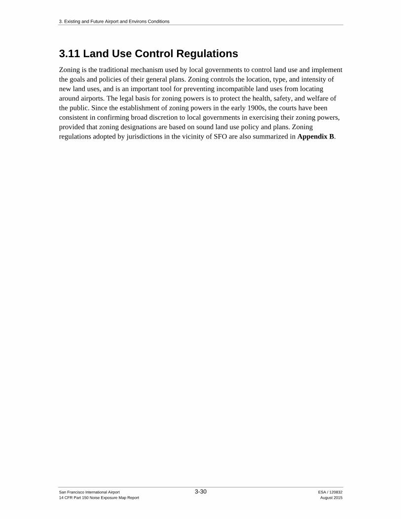
3.9 Generalized Existing Land Uses in the Airport Environs Exhibit 3-7 presents generalized existing land uses in the vicinity of SFO. Most of the airport environs are developed with urban/suburban development except for dedicated open space areas, parks and recreation areas, and the San Francisco Bay which is east, southeast, and northeast of SFO. There are few vacant land areas suitable for development in the region.
Land uses in the immediate vicinity of the Airport include heavy industrial uses, business/technology parks, commercial businesses, single-family and multi-family residential uses, and park and recreational uses. Several major transportation corridors traverse the area including U.S. 101, I-380, I-280, BART, and the Caltrain commuter rail line.
Existing land uses north of the Airport in the City of South San Francisco are primarily commercial and industrial. Large areas of commercial and light industrial land uses can also be found southeast of the Airport in the City of Burlingame. In the City of San Bruno, located immediately west of the Airport and U.S. 101, single family residential land uses predominate, with commercial uses concentrated along San Mateo Avenue and El Camino Real. This land use pattern continues southward into the City of Millbrae, with an increase in multi‐family residential uses in areas southwest of the Airport and U.S. 101. Areas northwest of the Airport in San Bruno and South San Francisco, including areas underneath the extended centerlines for Runways 28L and 28R, are also developed with single family and multi-family residential land uses.
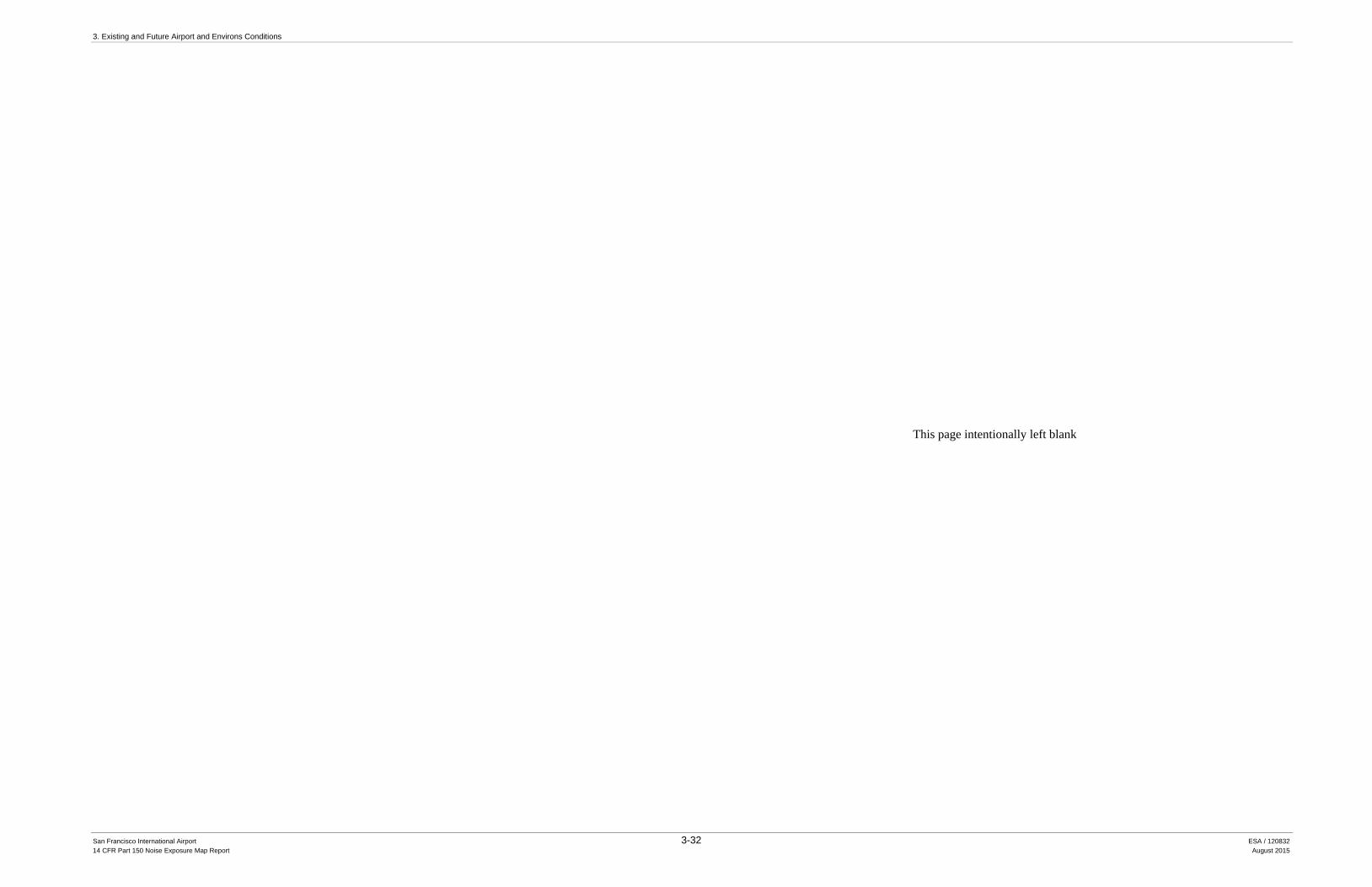
3.10 Generalized Planned Land Uses in the Airport Environs General plans and specific plans adopted by San Mateo County and eleven cities and towns in the airport environs were reviewed and are summarized in Appendix B. Generalized planned land uses in the airport environs are depicted on Exhibit 3-8. Exhibit 3-8 was developed using geographic information system data provided by the San Mateo County Planning and Building Department in 2014 and information contained in plans adopted by local jurisdictions in San Mateo County.
As shown on Exhibit 3-8, generalized planned land uses within the immediate vicinity of SFO consist primarily of commercial and industrial uses including transportation and utility infrastructure. Single family and multi-family residential uses are the predominant planned land uses in areas west of U.S. 101. San Mateo County and its incorporated jurisdictions also provide for a substantial amount of open space, park, and recreation areas; the most prominent of which includes the Golden Gate National Recreation Area in western San Mateo County, San Bruno Mountain, and miles of shoreline along both the San Francisco Bay and the Pacific Ocean. With the Bay Area’s strong emphasis on technology, large portions of San Mateo County and its cities are also designated for professional office, research and development, and light industrial uses.
3. Existing and Future Airport and Environs Conditions
San Francisco International Airport 3-30 ESA / 120832 14 CFR Part 150 Noise Exposure Map Report August 2015
3.11 Land Use Control Regulations Zoning is the traditional mechanism used by local governments to control land use and implement the goals and policies of their general plans. Zoning controls the location, type, and intensity of new land uses, and is an important tool for preventing incompatible land uses from locating around airports. The legal basis for zoning powers is to protect the health, safety, and welfare of the public. Since the establishment of zoning powers in the early 1900s, the courts have been consistent in confirming broad discretion to local governments in exercising their zoning powers, provided that zoning designations are based on sound land use policy and plans. Zoning regulations adopted by jurisdictions in the vicinity of SFO are also summarized in Appendix B.
3. Existing and Future Airport and Environs Conditions
San Francisco International Airport 3-32 ESA / 120832 14 CFR Part 150 Noise Exposure Map Report August 2015
This page intentionally left blank

3. Existing and Future Airport and Environs Conditions
San Francisco International Airport 3-34 ESA / 120832 14 CFR Part 150 Noise Exposure Map Report August 2015
This page intentionally left blank