chapter 3: electric current and direct-current...
TRANSCRIPT
Chapter 3
CP3 1 FYSL
Chapter 3: Electric Current And Direct-Current Circuits
3.1 Electric Conduction
L.O 3.1.1 Describe the microscopic model of current
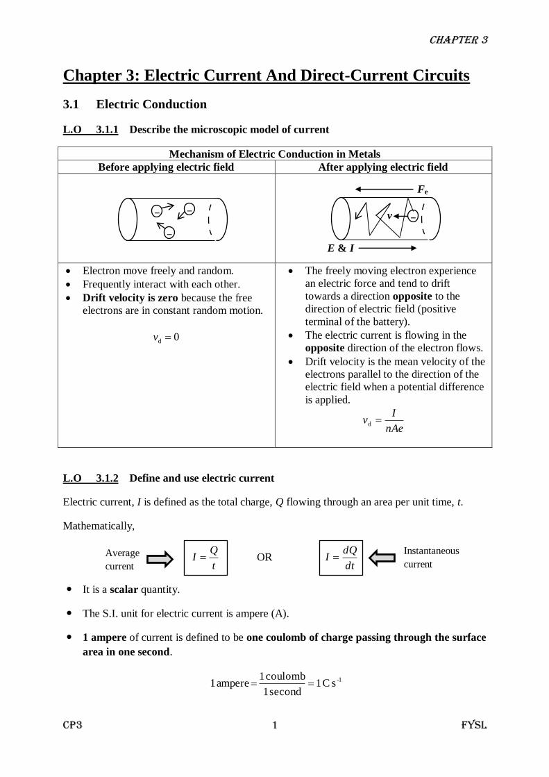
Mechanism of Electric Conduction in Metals
Before applying electric field After applying electric field
Electron move freely and random.
Frequently interact with each other.
Drift velocity is zero because the free
electrons are in constant random motion.
0d v
The freely moving electron experience
an electric force and tend to drift
towards a direction opposite to the
direction of electric field (positive
terminal of the battery).
The electric current is flowing in the
opposite direction of the electron flows.
Drift velocity is the mean velocity of the
electrons parallel to the direction of the
electric field when a potential difference
is applied.
nAe
Iv d
L.O 3.1.2 Define and use electric current
Electric current, I is defined as the total charge, Q flowing through an area per unit time, t.
Mathematically,
t
QI OR
dt
dQI
It is a scalar quantity.
The S.I. unit for electric current is ampere (A).
1 ampere of current is defined to be one coulomb of charge passing through the surface
area in one second.
1-s C 1second 1
coulomb 1 ampere 1
‒
‒
‒ ‒
Fe
E & I
v
Average
current
Instantaneous
current
Chapter 3
CP3 2 FYSL
3.2 Ohm’s Law and Resistivity
L.O 3.2.1 State and use Ohm’s law
Ohm’s law states that the potential difference across a conductor, V is directly proportional
to the current, I through it, if its physical conditions and the temperature are constant.
IV where T is constant
Mathematically,
V = IR
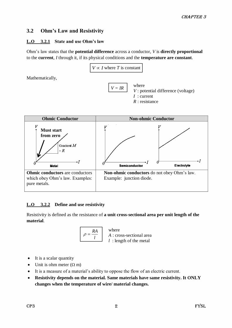
Ohmic Conductor Non-ohmic Conductor
Ohmic conductors are conductors
which obey Ohm’s law. Examples:
pure metals.
Non-ohmic conductors do not obey Ohm’s law.
Example: junction diode.
L.O 3.2.2 Define and use resistivity
Resistivity is defined as the resistance of a unit cross-sectional area per unit length of the
material.
l
RA
It is a scalar quantity
Unit is ohm meter ( m)
It is a measure of a material’s ability to oppose the flow of an electric current.
Resistivity depends on the material. Same materials have same resistivity. It ONLY
changes when the temperature of wire/ material changes.
Must start
from zero
where
V : potential difference (voltage)
I : current
R : resistance
where
A : cross-sectional area
l : length of the metal
Chapter 3
CP3 3 FYSL
3.3 Variation of Resistance with Temperature
L.O 3.3.1 Explain the effect of temperature on electrical resistance in metals
L.O 3.3.2 Use resistance, R = R0 [1+α (T ‒ T0)]
The resistance of a metal (conductor) depends on
the nature of the material,
(, resistivity)
the size of the conductor,
(l, the length and A, cross-sectional area)
the temperature of the conductor.
The resistance of metals increases with increasing temperature. (T ↑, R ↑)
Explanation:
1. As temperature increases, the ions of the conductor vibrate with greater amplitude.
2. More collisions occur between free electrons and ions.
3. These electrons are slowed down thus increases the resistance.
The fractional change in resistance per unit rise in temperature is known as temperature
coefficient of resistance, α.
TR
R
0
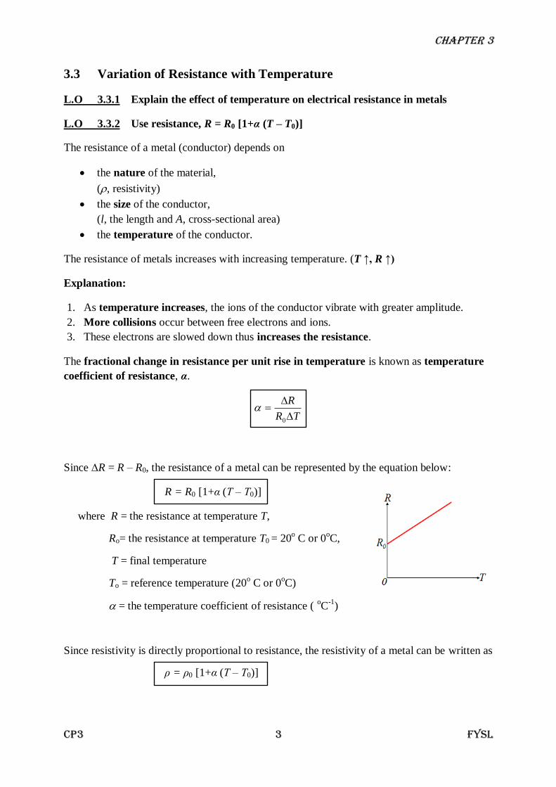
Since ∆R = R ‒ R0, the resistance of a metal can be represented by the equation below:
R = R0 [1+α (T ‒ T0)]
where R = the resistance at temperature T,
Ro= the resistance at temperature T0 = 20o C or 0
oC,
T = final temperature
To = reference temperature (20o C or 0
oC)
= the temperature coefficient of resistance ( oC
-1)
Since resistivity is directly proportional to resistance, the resistivity of a metal can be written as
ρ = ρ0 [1+α (T ‒ T0)]
Chapter 3
CP3 4 FYSL
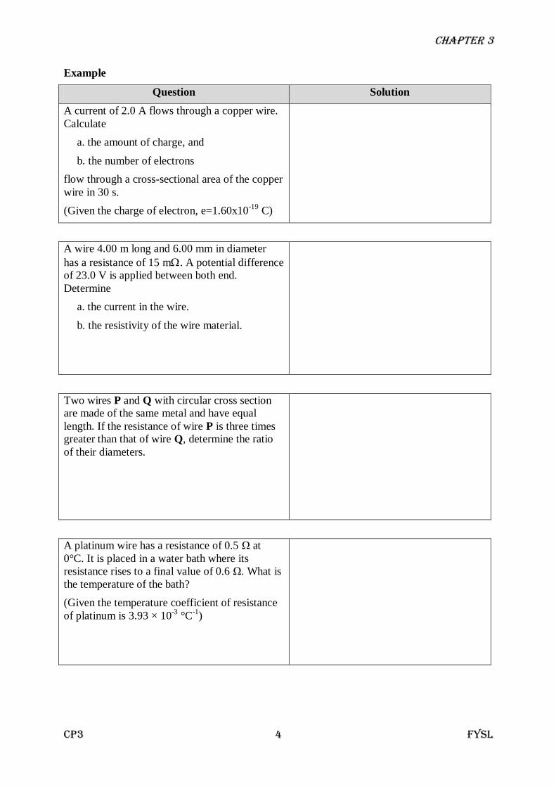
Example
Question Solution
A current of 2.0 A flows through a copper wire.
Calculate
a. the amount of charge, and
b. the number of electrons
flow through a cross-sectional area of the copper
wire in 30 s.
(Given the charge of electron, e=1.60x10⁻¹⁹
C)
A wire 4.00 m long and 6.00 mm in diameter
has a resistance of 15 m. A potential difference
of 23.0 V is applied between both end.
Determine
a. the current in the wire.
b. the resistivity of the wire material.
Two wires P and Q with circular cross section
are made of the same metal and have equal
length. If the resistance of wire P is three times
greater than that of wire Q, determine the ratio
of their diameters.
A platinum wire has a resistance of 0.5 Ω at
0°C. It is placed in a water bath where its
resistance rises to a final value of 0.6 Ω. What is
the temperature of the bath?
(Given the temperature coefficient of resistance
of platinum is 3.93 × 10⁻³
°C-1
)
Chapter 3
CP3 5 FYSL
Question Solution
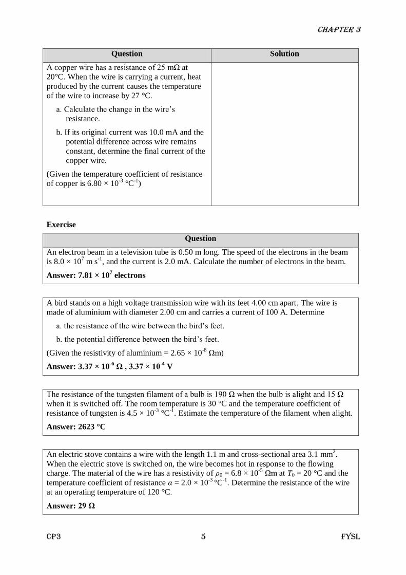
A copper wire has a resistance of 25 mΩ at
20°C. When the wire is carrying a current, heat
produced by the current causes the temperature
of the wire to increase by 27 °C.
a. Calculate the change in the wire’s
resistance.
b. If its original current was 10.0 mA and the
potential difference across wire remains
constant, determine the final current of the
copper wire.
(Given the temperature coefficient of resistance
of copper is 6.80 × 10⁻³
°C-1
)
Exercise
Question
An electron beam in a television tube is 0.50 m long. The speed of the electrons in the beam
is 8.0 × 10⁷ m s
-1, and the current is 2.0 mA. Calculate the number of electrons in the beam.
Answer: 7.81 × 10⁷ electrons
A bird stands on a high voltage transmission wire with its feet 4.00 cm apart. The wire is
made of aluminium with diameter 2.00 cm and carries a current of 100 A. Determine
a. the resistance of the wire between the bird’s feet.
b. the potential difference between the bird’s feet.
(Given the resistivity of aluminium = 2.65 × 10⁻⁸
Ωm)
Answer: 3.37 × 10⁻⁶
Ω , 3.37 × 10⁻⁴
V
The resistance of the tungsten filament of a bulb is 190 Ω when the bulb is alight and 15 Ω
when it is switched off. The room temperature is 30 °C and the temperature coefficient of
resistance of tungsten is 4.5 × 10⁻³
°C-1
. Estimate the temperature of the filament when alight.
Answer: 2623 °C
An electric stove contains a wire with the length 1.1 m and cross-sectional area 3.1 mm2.
When the electric stove is switched on, the wire becomes hot in response to the flowing
charge. The material of the wire has a resistivity of ρ0 = 6.8 × 10⁻⁵
Ωm at T0 = 20 °C and the
temperature coefficient of resistance α = 2.0 × 10⁻³
°C-1
. Determine the resistance of the wire
at an operating temperature of 120 °C.
Answer: 29 Ω

Chapter 3
CP3 6 FYSL
3.4 Electromotive Force (emf), internal resistance and potential difference
L.O 3.4.1 Define emf
L.O 3.4.2 Explain the relationship between emf of a battery and potential difference
across the battery terminals.
L.O 3.4.3 Use terminal voltage, V = ε ‒ Ir
Electromotive force (e.m.f.), is defined as the energy provided by the source (battery/
cell) to each unit charge that flows from the source.
Terminal potential difference (voltage), VAB is defined as the work done in bringing a
unit (test) charge from point B to point A.
VAB = VA ‒ VB
The unit for both e.m.f. and potential difference is volt (V).
Internal resistance, r is defined as the resistance of the chemicals inside the cell (battery)
between the poles.
NOTE!
a) VAB < ε when the battery of emf ε is connected to the external circuit with resistance R.
b) VAB > ε when the battery of emf ε is being charged by other battery.
c) VAB = ε when the battery of emf ε has no internal resistance (r = 0) and connected to the
external circuit with resistance R.
EXTRA KNOWLEDGE – HOW DO BATTERIES WORK?
Vlost
Vterminal
(VAB )
ε
I
R
r A B
Total resistance
in the circuit
where
ε : e.m.f.
R : external resistance
r : internal resistance
The chemical reaction in the battery causes a build-up of electrons at the anode. This
results in an electrical difference between the anode and the cathode. When there is
potential difference, the electrons want to rearrange themselves to get rid of this
difference; hence the electrons repel each other and try to go to a place with fewer
electrons. In a battery, the only place to go is to the cathode. But, the electrolyte keeps
the electrons from going straight from the anode to the cathode within the battery. When
the circuit is closed (a wire connects the cathode and the anode) the electrons will be
able to get to the cathode through wire. Anode
Cathode
Electrolyte
Chapter 3
CP3 7 FYSL
Example
Question Solution
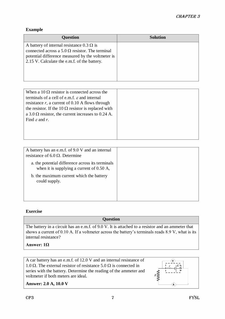
A battery of internal resistance 0.3 is
connected across a 5.0 resistor. The terminal
potential difference measured by the voltmeter is
2.15 V. Calculate the e.m.f. of the battery.
When a 10 resistor is connected across the
terminals of a cell of e.m.f. and internal
resistance r, a current of 0.10 A flows through
the resistor. If the 10 resistor is replaced with
a 3.0 resistor, the current increases to 0.24 A.
Find and r.
A battery has an e.m.f. of 9.0 V and an internal
resistance of 6.0 . Determine
a. the potential difference across its terminals
when it is supplying a current of 0.50 A,
b. the maximum current which the battery
could supply.
Exercise
Question
The battery in a circuit has an e.m.f. of 9.0 V. It is attached to a resistor and an ammeter that
shows a current of 0.10 A. If a voltmeter across the battery’s terminals reads 8.9 V, what is its
internal resistance?
Answer: 1Ω
A car battery has an e.m.f. of 12.0 V and an internal resistance of
1.0 . The external resistor of resistance 5.0 is connected in
series with the battery. Determine the reading of the ammeter and
voltmeter if both meters are ideal.
Answer: 2.0 A, 10.0 V

Chapter 3
CP3 8 FYSL
3.5 Electrical Energy and Power
L.O 3.5.1 Use power, P = IV and electrical energy, W = IVt
Electrical (potential) energy, W is the energy gained by the charge Q from a voltage source
(battery) having a terminal voltage V. The faster the electric charges are moving the more
electrical energy they carry.
The work done by the source on the charge is given by:
QVW
But ItQ (the amount of charges flow from negative terminal to positive terminal in time t),
VItW
Since V = IR, electrical energy can also be written as:
R
tVWRtIW
22 OR
The unit for electrical energy is Joule (J).
NOTE!
resistance internalby dissipatedEnergy resistance externalby dissipatedEnergy suppliedEnergy
Electric power is defined as the rate of energy delivered to the external circuit by the battery.
t
VIt
t
WP
IVP
Since V = IR, electrical power can also be written as:
R
VPRIP
22 OR
The unit for electrical power is Watt (W).
NOTE!
resistance internalby dissipatedPower resistance externalby dissipatedPower output Power
Chapter 3
CP3 9 FYSL
3.6 Resistors in Series and Parallel
L.O 3.6.1 Derive and determine effective resistance of resistors in series and parallel
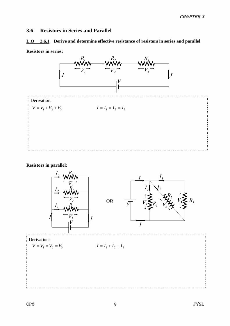
Resistors in series:
321 VVVV 321 IIII
Resistors in parallel:
321 VVVV 321 IIII
Derivation:
Derivation:
OR

Chapter 3
CP3 10 FYSL
Example
Question Solution
a. Calculate the resistance of a 40 W
automobile headlight designed for 12 V?
b. The current through a refrigerator of
resistance 12 Ω is 13 A. What is the power
consumed by the refrigerator?
In figure above, a battery with an e.m.f. of 12 V
and an internal resistance of 1.0 is connected
to a 5Ω resistor. Determine
a. the rate of energy transferred to electrical
energy in the battery,
b. the rate of heat dissipated in the battery,
c. the amount of heat loss in the 5.0
resistor if the current flows through it for 20
minutes.
For the circuit shown below,
Calculate :
a. the total resistance of the circuit.
b. the total current in the circuit.
c. the potential difference across 4.0 resistor.
Chapter 3
CP3 11 FYSL
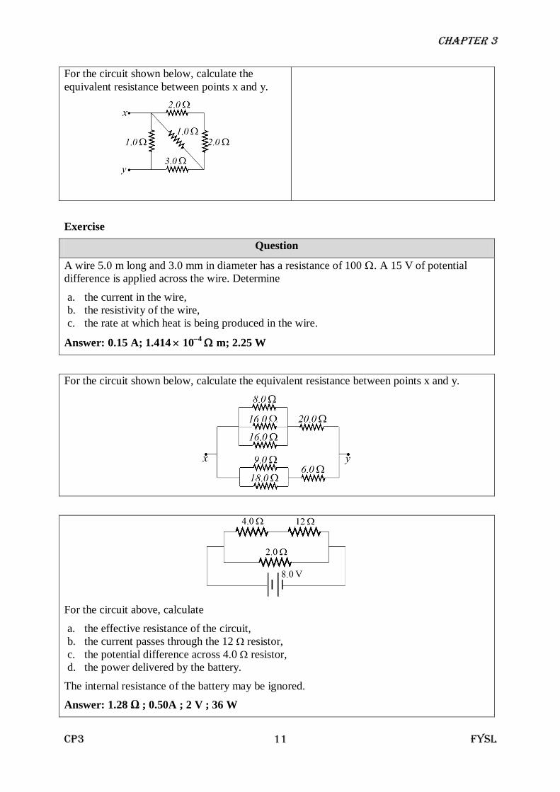
For the circuit shown below, calculate the
equivalent resistance between points x and y.
Exercise
Question
A wire 5.0 m long and 3.0 mm in diameter has a resistance of 100 . A 15 V of potential
difference is applied across the wire. Determine
a. the current in the wire,
b. the resistivity of the wire,
c. the rate at which heat is being produced in the wire.
Answer: 0.15 A; 1.414 104
m; 2.25 W
For the circuit shown below, calculate the equivalent resistance between points x and y.
For the circuit above, calculate
a. the effective resistance of the circuit,
b. the current passes through the 12 resistor,
c. the potential difference across 4.0 resistor,
d. the power delivered by the battery.
The internal resistance of the battery may be ignored.
Answer: 1.28 Ω ; 0.50A ; 2 V ; 36 W
Chapter 3
CP3 12 FYSL
3.7 Kirchhoff’s Laws
L.O 3.7.1 State and use Kirchhoff’s Laws
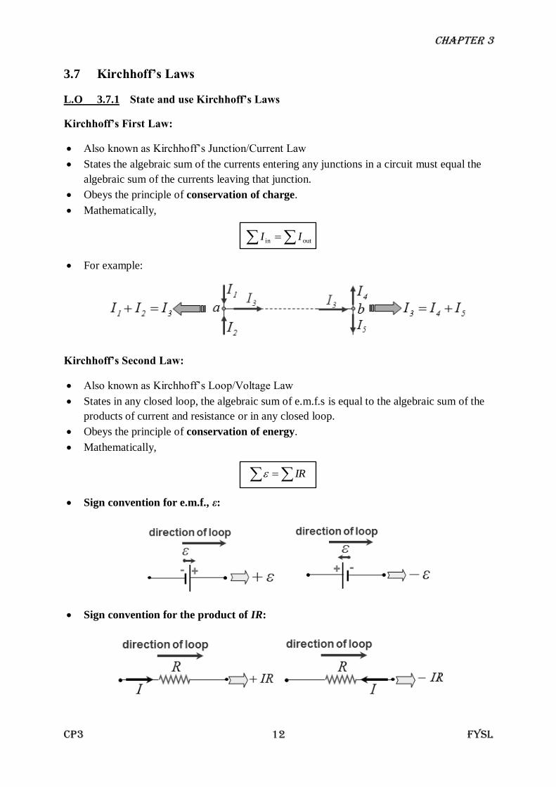
Kirchhoff’s First Law:
Also known as Kirchhoff’s Junction/Current Law
States the algebraic sum of the currents entering any junctions in a circuit must equal the
algebraic sum of the currents leaving that junction.
Obeys the principle of conservation of charge.
Mathematically,
outin II
For example:
Kirchhoff’s Second Law:
Also known as Kirchhoff’s Loop/Voltage Law
States in any closed loop, the algebraic sum of e.m.f.s is equal to the algebraic sum of the
products of current and resistance or in any closed loop.
Obeys the principle of conservation of energy.
Mathematically,
IR
Sign convention for e.m.f., ε:
Sign convention for the product of IR:

Chapter 3
CP3 13 FYSL
Problem Solving Strategy (for two closed circuits)
1. Label the diagram
2. Apply Kirchhoff’s First Law → 1 equation
3. Apply Kirchhoff’s Second Law → 2 equations
4. Use scientific calculator to solve the simultaneous equations
Example
Question: Calculate I, εX and R Step 1: Label the diagram
Step 2: Apply Kirchhoff’s First Law Step 3: Apply Kirchhoff’s Second Law
Loop 1:
Loop 2
Step 4: Solving the simultaneous equations
Chapter 3
CP3 14 FYSL
Example
Question Solution
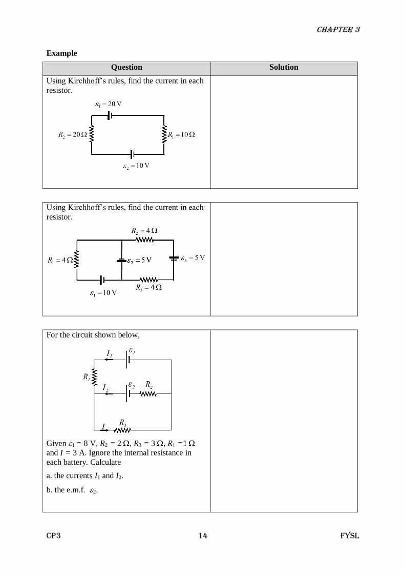
Using Kirchhoff’s rules, find the current in each
resistor.
Using Kirchhoff’s rules, find the current in each
resistor.
For the circuit shown below,
Given 1 = 8 V, R2 = 2 , R3 = 3 , R1 =1
and I = 3 A. Ignore the internal resistance in
each battery. Calculate
a. the currents I1 and I2.
b. the e.m.f. 2.
Chapter 3
CP3 15 FYSL
Example
Question Solution
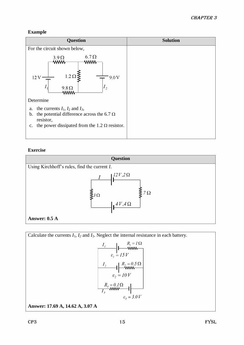
For the circuit shown below,
Determine
a. the currents I1, I2 and I3,
b. the potential difference across the 6.7
resistor,
c. the power dissipated from the 1.2 resistor.
Exercise
Question
Using Kirchhoff’s rules, find the current I.
Answer: 0.5 A
Calculate the currents I1, I2 and I3. Neglect the internal resistance in each battery.
Answer: 17.69 A, 14.62 A, 3.07 A

Chapter 3
CP3 16 FYSL
3.8 Potential Divider
L.O 3.8.1 Explain principle of potential divider
L.O 3.8.2 Use equation of potential divider
A potential divider is used as a source of variable voltage. It produces an output voltage that
is a fraction of the supply voltage.
3.9 Potentiometer and Wheatstone Bridge
L.O 3.9.1 Explain the principles of potentiometer and Wheatstone Bridge and their
application
L.O 3.9.2 Use related equation for potentiometer and for Wheatstone Bridge
Potentiometer
The working of potentiometer is based upon the fact that fall of the potential across any portion
of the wire is directly proportional to the length of the wire provided wire has uniform cross
section area and constant current flowing through it. The potentiometer is balanced when the
jockey (sliding contact) is at such a position on wire AB that there is no current through the
galvanometer.
If the galvanometer shows deflection in one direction only, it may be due to:
• The connections of the terminals of the cells are wrong. The positive terminal of the cell
must be connected to the positive terminal of another cell.
• The e.m.f. of the unknown cell is more than the e.m.f. of the cell connected across the
wire of the potentiometer, AB.
• The connections are not tight and the current does not flow in certain part of the circuit.
VRR
RV
21
11 OR V
RR
RV
21
22 V
ll
lV
21
11 OR V
ll
lV
21
22
Chapter 3
CP3 17 FYSL
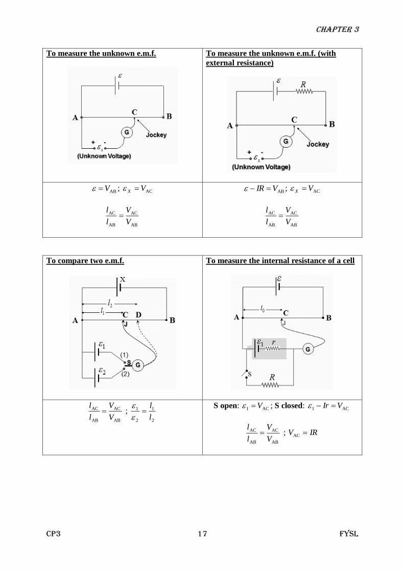
To measure the unknown e.m.f.
To measure the unknown e.m.f. (with
external resistance)
ABV ; ACVX
AB
AC
AB
AC
V
V
l
l
ABVIR ; ACVX
AB
AC
AB
AC
V
V
l
l
To compare two e.m.f.
To measure the internal resistance of a cell
AB
AC
AB
AC
V
V
l
l ;
2
1
2
1
l
l
S open: AC1 V ; S closed: AC1 VIr
AB
AC
AB
AC
V
V
l
l ; IRV AC
Chapter 3
CP3 18 FYSL
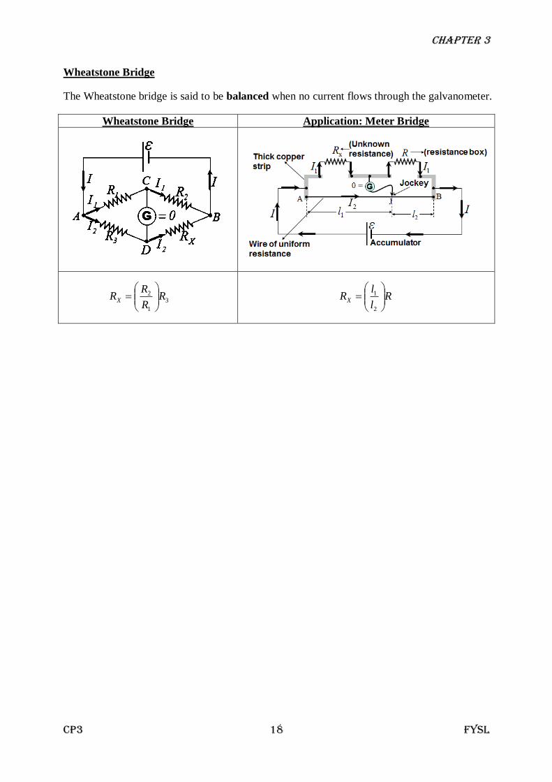
Wheatstone Bridge
The Wheatstone bridge is said to be balanced when no current flows through the galvanometer.
Wheatstone Bridge Application: Meter Bridge
3
1
2 RR
RRX
R
l
lRX
2
1

Chapter 3
CP3 19 FYSL
Example
Question Solution
For the circuit shown below,
Determine
d. the currents I1, I2 and I3,
e. the potential difference across the 6.7
resistor,
f. the power dissipated from the 1.2 resistor.
Exercise
Question
Using Kirchhoff’s rules, find the current I.
Answer: 0.5 A
Calculate the currents I1, I2 and I3. Neglect the internal resistance in each battery.
Answer: 17.69 A, 14.62 A, 3.07 A
Chapter 3
CP3 20 FYSL
Example
Question Solution
Resistors of 3.0 Ω and 6.0 Ω are connected in
series to a 12.0 V battery of negligible internal
resistance. Determine the potential difference
across the
a. 3.0 Ω resistor
b. 6.0 Ω resistors
Consider a potentiometer. If a standard battery
with an e.m.f. of 1.0186 V is used in the circuit.
When the resistance is 36 Ω, the galvanometer
reads zero. If the standard battery is replaced by
an unknown e.m.f. the galvanometer reads zero
when the resistance is adjusted to 48 Ω. What is
the value of the unknown e.m.f.?
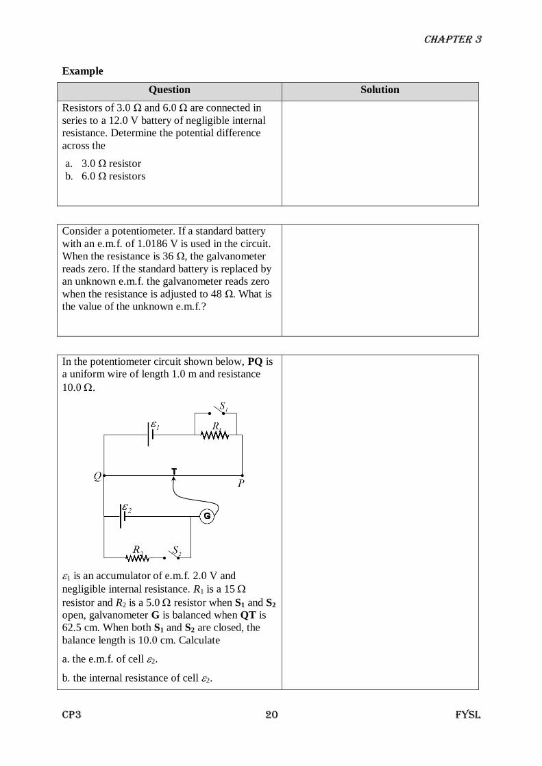
In the potentiometer circuit shown below, PQ is
a uniform wire of length 1.0 m and resistance
10.0 .
1 is an accumulator of e.m.f. 2.0 V and
negligible internal resistance. R1 is a 15
resistor and R2 is a 5.0 resistor when S1 and S2
open, galvanometer G is balanced when QT is
62.5 cm. When both S1 and S2 are closed, the
balance length is 10.0 cm. Calculate
a. the e.m.f. of cell 2.
b. the internal resistance of cell 2.
Chapter 3
CP3 21 FYSL
Question Solution
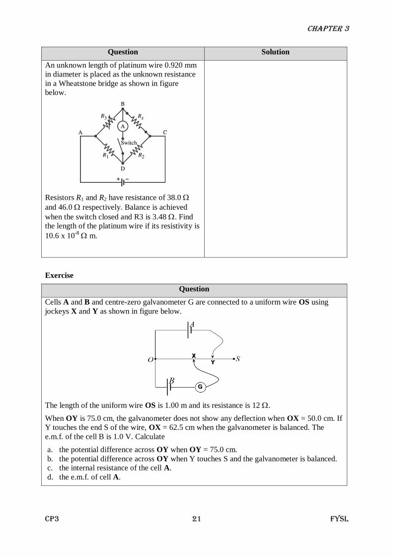
An unknown length of platinum wire 0.920 mm
in diameter is placed as the unknown resistance
in a Wheatstone bridge as shown in figure
below.
Resistors R1 and R2 have resistance of 38.0
and 46.0 respectively. Balance is achieved
when the switch closed and R3 is 3.48 . Find
the length of the platinum wire if its resistivity is
10.6 x 10⁻⁸
m.
Exercise
Question
Cells A and B and centre-zero galvanometer G are connected to a uniform wire OS using
jockeys X and Y as shown in figure below.
The length of the uniform wire OS is 1.00 m and its resistance is 12 .
When OY is 75.0 cm, the galvanometer does not show any deflection when OX = 50.0 cm. If
Y touches the end S of the wire, OX = 62.5 cm when the galvanometer is balanced. The
e.m.f. of the cell B is 1.0 V. Calculate
a. the potential difference across OY when OY = 75.0 cm.
b. the potential difference across OY when Y touches S and the galvanometer is balanced.
c. the internal resistance of the cell A.
d. the e.m.f. of cell A.