chapter 2e. guide signs freeways and ......symbols, and (c) short legends for quick comprehension....
TRANSCRIPT

CHAPTER 2E. GUIDE SIGNS—FREEWAYS AND EXPRESSWAYS
Section 2E.01 Scope of Freeway and Expressway Guide Sign StandardsSupport:
These standards provide a uniform and effective system of highway signing for high-volume, high-speed motorvehicle traffic on freeways and expressways. The requirements and specifications for expressway signing exceedthose for conventional roads (see Chapter 2D), but are less than those for freeway signing. Since there are manygeometric design variables to be found in existing roads, a signing concept commensurate with prevailingconditions is the primary consideration. Section 2A.01 includes definitions of freeway and expressway.
Guide signs for freeways and expressways are primarily identified by the name of the sign rather than by anassigned sign code. Guidelines for the design of guide signs for freeways and expressways are provided in Chapter8 (Design Guidelines) of the "Standard Highway Signs" book (see Section 1A.11).Standard:
The standards prescribed herein for freeway or expressway guide signing shall apply to any highwaythat meets the definition of such facilities.
Section 2E.02 Freeway and Expressway Signing PrinciplesSupport:
The development of a signing system for freeways and expressways is approached on the premise that thesigning is primarily for the benefit and direction of road users who are not familiar with the route or area. Thesigning furnishes road users with clear instructions for orderly progress to their destinations. Sign installations arean integral part of the facility and, as such, are best planned concurrently with the development of highway locationand geometric design. For optimal results, plans for signing are analyzed during the earliest stages of preliminarydesign, and details are correlated as final design is developed. The excessive signing found on many majorhighways usually is the result of using a multitude of signs that are too small and that are poorly designed andplaced to accomplish the intended purpose.
Freeway and expressway signing is to be considered and developed as a planned system of installations. Anengineering study is sometimes necessary for proper solution of the problems of many individual locations, but, inaddition, consideration of an entire route is necessary.Guidance:
Road users should be guided with consistent signing on the approaches to interchanges, when they drive fromone State to another, and when driving through rural or urban areas. Because geographical, geometric, andoperating factors regularly create significant differences between urban and rural conditions, the signing shouldtake these conditions into account.
Guide signs on freeways and expressways should serve distinct functions as follows:A. Give directions to destinations, or to streets or highway routes, at intersections or interchanges;B. Furnish advance notice of the approach to intersections or interchanges;C. Direct road users into appropriate lanes in advance of diverging or merging movements;D. Identify routes and directions on those routes;E. Show distances to destinations;F. Indicate access to general motorist services, rest, scenic, and recreational areas; andG. Provide other information of value to the road user.
Section 2E.03 GeneralSupport:
Signs are designed so that they are legible to road users approaching them and readable in time to permitproper responses. Desired design characteristics include: (a) long visibility distances, (b) large lettering andsymbols, and (c) short legends for quick comprehension.Standard:
Standard shapes and colors shall be used so that traffic signs can be promptly recognized by roadusers.
Section 2E.04 Color of Guide SignsStandard:
Guide signs on freeways and expressways, except as noted herein, shall have white letters, symbols,and borders on a green background.
Indiana 2008 Edition Page 2E-1
Sect. 2E.1 to 2E.04

Support:Color requirements for route signs and trailblazers, signs with blank-out or changeable messages, signs for
services, rest areas, park and recreational areas, and for certain miscellaneous signs are specified in the individualsections dealing with the particular sign or sign group.
Section 2E.05 Retroreflection or IlluminationStandard:
Letters, numerals, symbols, and borders of all guide signs shall be retroreflectorized. The background ofall guide signs that are not independently illuminated shall be retroreflective.Support:
Where there is no serious interference from extraneous light sources, retroreflectorized ground-mountedsigns usually provide adequate nighttime visibility.
On freeways and expressways where much driving at night is done with low-beam headlights, the amount ofheadlight illumination incident to an overhead sign display is relatively small.Guidance:
Overhead sign installations should be illuminated unless an engineering study shows that retroreflectorizationalone will perform effectively. The type of illumination chosen should provide effective and reasonably uniformillumination of the sign face and message.
Section 2E.06 Characteristics of Urban SigningSupport:
Urban conditions are characterized not so much by City limits or other arbitrary boundaries, as by thefollowing features:
A. Mainline roadways with more than two lanes in each direction;B. High traffic volumes on the through roadways;C. High volumes of traffic entering and leaving interchanges;D. Interchanges closely spaced;E. Roadway and interchange lighting;F. Three or more interchanges serving the major City;G. A loop, circumferential, or spur serving a sizable portion of the urban population; andH. Visual clutter from roadside development.Operating conditions and road geometrics on urban freeways and expressways usually make special sign
treatments desirable, including:A. Use of Interchange Sequence signs (see Section 2E.37);B. Use of sign spreading to the maximum extent possible (see Section 2E.10);C. Elimination of service signing (see Section 2E.51);D. Reduction to a minimum of post-interchange signs (see Section 2E.35);E. Display of advance signs at distances closer to the interchange, with appropriate adjustments in the
legend (see Section 2E.30);F. Use of overhead signs on roadway structures and independent sign supports (see Section 2E.22);G. Use of diagrammatic signs in advance of intersections and interchanges (see Section 2E.19); andH. Frequent use of street names as the principal message in guide signs.Lower speeds which are often characteristic of urban operations do not justify lower signing standards.
Typical traffic patterns are more complex for the road user to negotiate, and large, easy-to-read legends are,therefore, just as necessary as on rural highways.
Section 2E.07 Characteristics of Rural SigningSupport:
Rural areas ordinarily have greater distances between interchanges, which permits adequate spacing for thesequences of signs on the approach to and departure from each interchange. However, the absence of traffic inadjoining lanes and on entering or exiting ramps often adds monotony or inattention to rural driving. Thisincreases the importance of signs that call for decisions or actions.
Page 2E-2 Indiana 2008 Edition
Sect. 2E.04 to 2E.07

Guidance:Where there are long distances between interchanges and the alignment is relatively unchanging, signs should
be positioned for their best effect on road users. The tendency to group all signing in the immediate vicinity of ruralinterchanges should be avoided by considering the entire route in the development of sign plans. Extra effortshould be given to the placement of signs at natural target locations to command the attention of the road user,particularly when the message requires an action by the road user.
Section 2E.08 Memorial Highway SigningGuidance:
Freeways and expressways should not be signed as memorial highways. If a route, bridge, or highwaycomponent is officially designated as a memorial, and if notification of the memorial is to be made on thehighway right-of-way, such notification should consist of installing a memorial plaque in a rest area, scenicoverlook, recreational area, or other appropriate location where parking is provided with the signinginconspicuously located relative to vehicle operations along the highway.Option:
If the installation of a memorial plaque off the main roadway is not practical, a memorial sign may beinstalled on the mainline.Standard:
Where such memorial signs are installed on the mainline, (1) memorial names shall not appear ondirectional guide signs, (2) memorial signs shall not interfere with the placement of any other necessaryhighway signing, and (3) memorial signs shall not compromise the safety or efficiency of traffic flow. Thememorial signing shall be limited to one sign at an appropriate location in each route direction.
Section 2E.09 Amount of Legend on Guide SignsGuidance:
No more than two destination names or street names should be shown on any Advance Guide sign or ExitDirection sign. A City name and street name on the same sign should be avoided. Where two or three signs areplaced on the same supports, destinations or names should be limited to one per sign, or to a total of three in thedisplay. Sign legends should not exceed three lines of copy.Option:
Sign legends may include symbols, route numbers, arrows, cardinal directions, and exit instructions.
Section 2E.10 Number of Signs at an Overhead Installation and Sign SpreadingGuidance:
If overhead signs are warranted, as set forth in Section 2A.17, the number of signs at these locations should belimited to only those essential in communicating pertinent destination information to the road user. Exit Directionsigns for a single exit and the Advance Guide signs should have only one panel with one or two destinations.Regulatory signs, such as speed limits, should not be used in conjunction with overhead guide sign installations.Because road users have limited time to read and comprehend sign messages, there should not be more than threeguide signs displayed at any one location either on the overhead structure or its support.Option:
At overhead locations, more than one sign may be installed to advise of a multiple exit condition at aninterchange. If the roadway ramp or crossing roadway has complex or unusual geometrics, additional signs withconfirming messages may be provided to properly guide the road user.Support:
Sign spreading is a concept where major overhead signs are spaced so that road users are not overloadedwith a group of signs at a single location. Figure 2E-1 illustrates an example of sign spreading.Guidance:
Where overhead signing is used, sign spreading should be used at all single exit interchanges and to theextent possible at multi-exit interchanges. Sign spreading should be accomplished by use of the following:
A. The Exit Direction sign should be the only sign used in the vicinity of the gore (other than the Gore sign).It should be located overhead near the theoretical gore and generally on an overhead sign supportstructure.
B. The Advance Guide sign to indicate the next interchange exit should be placed near the crossroadlocation. If the crossroad goes over the mainline, the Advance Guide sign should be placed on theovercrossing structure.
Indiana 2008 Edition Page 2E-3
Sect. 2E.07 to 2E.10
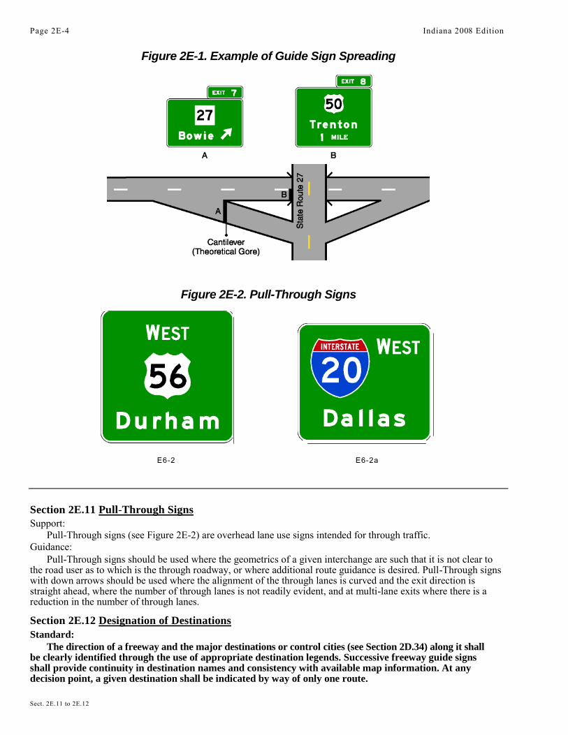
Figure 2E-1. Example of Guide Sign Spreading
Figure 2E-2. Pull-Through Signs
E6-2 E6-2a
Section 2E.11 Pull-Through SignsSupport:
Pull-Through signs (see Figure 2E-2) are overhead lane use signs intended for through traffic.Guidance:
Pull-Through signs should be used where the geometrics of a given interchange are such that it is not clear tothe road user as to which is the through roadway, or where additional route guidance is desired. Pull-Through signswith down arrows should be used where the alignment of the through lanes is curved and the exit direction isstraight ahead, where the number of through lanes is not readily evident, and at multi-lane exits where there is areduction in the number of through lanes.
Section 2E.12 Designation of DestinationsStandard:
The direction of a freeway and the major destinations or control cities (see Section 2D.34) along it shallbe clearly identified through the use of appropriate destination legends. Successive freeway guide signsshall provide continuity in destination names and consistency with available map information. At anydecision point, a given destination shall be indicated by way of only one route.
Page 2E-4 Indiana 2008 Edition
Sect. 2E.11 to 2E.12

Guidance:Control city legends should be used in the following situations along a freeway:A. At interchanges between freeways;B. At separation points of overlapping freeway routes;C. On directional signs on intersecting routes, to guide traffic entering the freeway;D. On Pull-Through signs; andE. On the bottom line of post-interchange distance signs.
Support:Continuity of destination names is also useful on expressways serving long-distance or intrastate travel.The determination of major destinations or control cities is important to the quality of service provided by
the freeway. Control cities on freeway guide signs are selected by the States and are contained in the “List of Control Cities for Use in Guide Signs on Interstate Highways,” published and available from American Association of State and Highway Transportation Officials (see Page i for AASHTO’s address).
Section 2E.13 Size and Style of Letters and SignsStandard:
With all freeway and expressway signs, the message dimensions shall be determined first, and the outsidesign dimensions secondarily. Word messages in the legend of expressway guide signs shall be in letters atleast 200 mm (8 in) high. Larger lettering shall be used for major guide signs at or in advance of interchangesand for all overhead signs. Minimum numeral and letter sizes for expressway guide signs according tointerchange classification, type of sign and component of sign legend are shown in Tables 2E-1 and 2E-2.Minimum numeral and letter sizes for freeway guide signs, according to interchange classification, type ofsign, and component of sign legend, appear in Tables 2E-3 and 2E-4. All names of places, streets, andhighways on freeway and expressway guide signs shall be composed of lower-case letters with initial upper-case letters. The letters and the numerals used shall be Series E(M) of the “Standard Highway Signs” book (see Section 1A.11). Other word legends shall be in capital letters. Interline and edge spacing shall be asspecified in Section 2E.14.
Lettering size on freeway and expressway signs shall be the same for both rural and urban conditions.Support:
Sign size is determined primarily in terms of the length of the message and the size of the lettering necessary forproper legibility. Letter style and height, and arrow design have been standardized for freeway and expresswaysigns to assure uniform and effective application.
Designs for upper-case, lower-case, and capital alphabets together with tables of recommended letterspacing, are shown in the “Standard Highway Signs” book.Guidance:
Where upper- and lower-case lettering is used, the initial upper-case letters should be approximately 1.33times the “loop” height of the lower-case letters. Freeway lettering sizes (see Tables 2E-3 and 2E-4) should beused when expressway geometric design is comparable to freeway standards.
Other sign letter size requirements not specifically identified elsewhere in this Manual should be guided bythese specifications. Abbreviations should be kept to a minimum.Support:
A sign mounted over a particular roadway lane to which it applies might have to be limited in horizontaldimension to the width of the lane, so that another sign can be placed over an adjacent lane. The necessity tomaintain proper vertical clearance might also place a further limitation on the size of the overhead sign and thelegend that can be accommodated.
Section 2E.14 lnterline and Edge SpacingGuidance:
Interline spacing of upper-case letters should be approximately three-fourths the average of upper-case letterheights in adjacent lines of letters.
The spacings to the top and bottom borders should be equal to the average of the letter height of the adjacentline of letters. The lateral spacing to the vertical borders should be essentially the same as the height of the largestletter.
Indiana 2008 Edition Page 2E-5
Sect. 2E.12 to 2E.14

Table 2E-1. Minimum Letter and Numeral Sizes for ExpresswayGuide Signs According to Interchange Classification
(Sizes shown in millimeters)Type of Interchange (see Section 2E.29)
MajorType of SignCategory a Category b Intermediate Minor Overhead
A. Advance Guide, Exit Direction, and Overhead Guide Signs .Exit Plaque
Word 250 250 250 200 250Numeral and Letter 375 375 375
300375
Interstate Route SignNumeral 450 ----- ----- ----- 4501 or 2 Digit Shield 900 x 900 ----- ----- ----- 900 x 9003 Digit Shield 1125 x 900 ----- ----- ----- 1125 x 900
U.S. or State Route SignNumeral 450 450 450 300 4501 or 2 Digit Shield 900 x 900 900 x 900 900 x 900 600 x 600 900 x 9003 Digit Shield 1125 x 900 1125 x 900 1125 x 900 750 x 600 1125 x 900
Alternate (Example: U.S. Alt. 56)Letters 375 300 300 250 300Numeral 450 375 375 300 375
Cardinal DirectionFirst Letter 450 375 300 250 375Rest of Word 375 300 250 200 300
Name of DestinationUpper-Case Letters 500 400 330 265 400Lower-Case Letters 375 300 250 200 300
Distance Number 450 375 300 250 375Distance Fraction 300 250 250 200 250Distance Word 300 250 250 200 250Action Message Word 250 250 250 200 250B. Gore Signs .
Word 250 250 250 200 -----Numeral & Letter 300 300 300 250 -----
Section 2E.15 Sign BordersStandard:Signs shall have a border of the same color as the legend in order to outline their distinctive shape andthereby give them easy recognition and a finished appearance.Guidance:
Guide signs should have a border width of 50 mm (2 in).Corner radii of sign borders should be 225 mm (9 in).
Option:The sign material in the area outside of the corner radius may be trimmed.
Page 2E-6 Indiana 2008 Edition
Sect. 2E.15

Table 2E-1. Minimum Letter and Numeral Sizes for ExpresswayGuide Signs According to Interchange Classification
(Sizes shown in inches)Type of Interchange (see Section 2E.29)
MajorType of SignCategory a Category b Intermediate Minor Overhead
A. Advance Guide, Exit Direction, and Overhead Guide Signs .Exit Plaque
Word 10 10 10 8 10Numeral and Letter 15 15 15 12 15
Interstate Route SignNumeral 18 ----- ----- ----- 181 or 2 Digit Shield 36 x 36 ----- ----- ----- 36 x 363 Digit Shield 45 x 36 ----- ----- ----- 45 x 36
U.S. or State Route SignNumeral 18 18 18 12 181 or 2 Digit Shield 36 x 36 36 x 36 36 x 36 24 x 24 36 x 363 Digit Shield 45 x 36 45 x 36 45 x 36 30 x 24 45 x 36
Alternate (Example: U.S. Alt. 56)Letters 15 12 12 10 12Numeral 18 15 15 12 15
Cardinal DirectionFirst Letter 18 15 12 10 15Rest of Word 15 12 10 8 12
Name of DestinationUpper-Case Letters 20 16 13.3 10.6 16Lower-Case Letters 15 12 10 8 12
Distance Number 18 15 12 10 15Distance Fraction 12 10 10 8 10Distance Word 12 10 10 8 10Action Message Word 10 10 10 8 10B. Gore Signs .
Word 10 10 10 8 -----Numeral & Letter 12 12 12 10 -----
____________________________________________________________________________________________
Section 2E.16 AbbreviationsGuidance:Abbreviations should be kept to a minimum; however, they are useful when complete destination messagesproduce excessively long signs. If used, abbreviations should be unmistakably recognized by road users (seeSection 1A.14).Periods should not be used unless a cardinal direction is abbreviated as part of a destination name.Standard:The words NORTH, SOUTH, EAST, and WEST shall not be abbreviated when used with route signsto indicate cardinal directions on guide signs.Section 2E.17 SymbolsStandard:Symbol designs shall be essentially like those shown in this Manual and in the “Standard HighwaySigns” book (see Section 1A.11).
Indiana 2008 Edition Page 2E-7
Sect. 2E.16 to 2E.17

Table 2E-2. Minimum Letter and Numeral Sizes for ExpresswayGuide Signs According to Sign Type (Sheet 1 of 2)
Type of Sign Minimum Size (mm) Minimum Size (inches)
A. Pull-Through Signs .Destination–Upper-Case Letters 330 13.3Destination–Lower-Case Letters 250 10Route Sign as Message
Cardinal Direction 250 101–or 2–Digit Shield 900 x 900 36 x 363–Digit Shield 1125 x 900 45 x 36
B. Supplemental Guide Signs .Exit Number Word 200 8Exit Number Numeral and Letter 300 12Place Name–Upper-Case Letters 265 10.6Place Name–Lower-Case Letters 200 8Action Message 200 8
C. Changeable Message Sign .Characters 265* 10.6*
D. Interchange Sequence .Work–Upper-Case Letters 265 10.6Word–Lower-Case Letters 200 8Numeral 250 10Fraction 200 8
E. Next X Exits Sign .Place Name–Upper-Case Letters 265 10.6Place Name–Lower-Case Letters 200 8NEXT X EXITS 200 8
F. Distance Signs .Word–Upper-Case Letters 200 8Word–Lower-Case Letters 150 5Numeral 200 8
G. General Service Signs .Exit Number Word 200 8Exit Number Numeral and Letter 300 12Services 200 8
H. Rest Area and Scenic Area Signs .Word 250 10Distance Numeral 300 12Distance Fraction 200 8Distance Word 250 10Action Message Word 250 10
Page 2E-8 Indiana 2008 Edition
Sect. 2E.17

Table 2E-2. Minimum Letter and Numeral Sizes for ExpresswayGuide Signs According to Sign Type (Sheet 2 of 2)
Type of Sign Minimum Size (mm) Minimum Size (inches)
I. Reference Location SignsWord 100 4Numeral 250 10
J. Boundary and Orientation SignsWord— Upper-Case Letters 200 8Word— Lower-Case Letters 150 6
K. Next Exit and Next Services SignsWord and Numeral 200 8
L. Exit Only SignsWord 300 12
*Changeable Message Signs may often require larger sizes than the minimum. A size of 450 mm (18 in)should be used where traffic speeds are greater than 90 km/h (55 mph), in areas of persistent inclementweather, or where complex driving tasks are involved.
Guidance:A special effort should be made to balance legend components for maximum legibility of the symbol with
the rest of the sign.Option:
Educational plaques may be used below symbol signs where needed.Section 2E.18 Arrows for Interchange Guide SignsStandard:
On all Exit Direction signs, both overhead and ground mounted, arrows shall be upward slanting andshall be located on the side of the sign consistent with the direction of the exiting movement, or centeredbeneath the destination lettering.
Downward pointing arrows shall be used only for overhead guide signs to prescribe lane assignmentfor traffic bound for a destination or route that can be reached only by being in the designated lane(s).Option:
Downward pointing arrows may be tilted where it is desired to emphasize the separation of roadways.Support:
Examples of arrows for use on guide signs are shown in Figure 2D-2. Detailed dimensions of arrows areprovided in the “Standard Highway Signs” book (see Section 1A.11).
Section 2E.19 Diagrammatic SignsSupport:
Diagrammatic signs are guide signs that show a graphic view of the exit arrangement in relationship to themain highway. Use of such guide signs has been shown to be superior to conventional guide signs for someinterchanges.Standard:
Diagrammatic signs shall be designed in accordance with the following criteria:A. The graphic legend shall be of a plan view showing the off-ramp arrangement (see Figure 2E-3).B. No other symbols or route shields shall be used as a substitute for arrowheads.C. They shall not be installed at the exit direction location (see Section 2E.33).D. The EXIT ONLY panel shall not be used on diagrammatic signs at any major split.
Indiana 2008 Edition Page 2E-9
Sect. 2E.17 to 2E.19
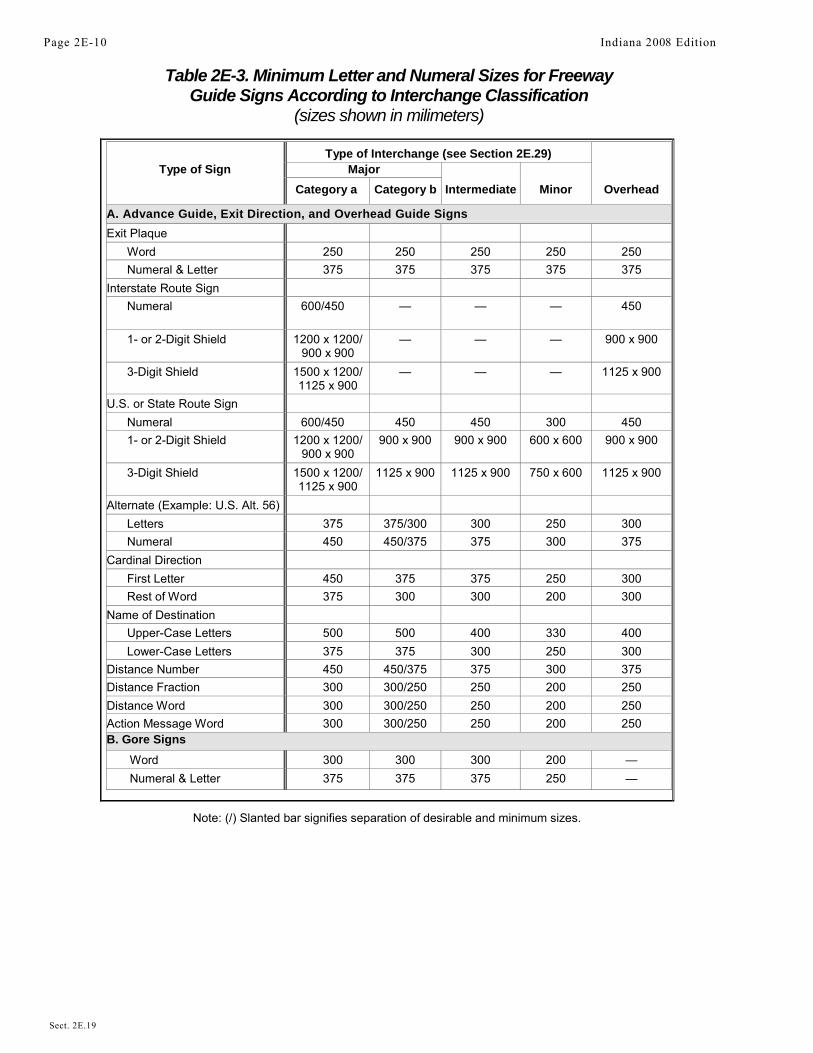
Table 2E-3. Minimum Letter and Numeral Sizes for FreewayGuide Signs According to Interchange Classification
(sizes shown in milimeters)
Type of Interchange (see Section 2E.29)Type of Sign Major
Category a Category b Intermediate Minor Overhead
A. Advance Guide, Exit Direction, and Overhead Guide Signsand Overhead Guide SignsExit Plaque
Word 250 250 250 250 250Numeral & Letter 375 375 375 375 375
Interstate Route SignNumeral 600/450 — — — 450
1- or 2-Digit Shield 1200 x 1200/900 x 900
— — — 900 x 900
3-Digit Shield 1500 x 1200/1125 x 900
— — — 1125 x 900
U.S. or State Route SignNumeral 600/450 450 450 300 4501- or 2-Digit Shield 1200 x 1200/
900 x 900900 x 900 900 x 900 600 x 600 900 x 900
3-Digit Shield 1500 x 1200/1125 x 900
1125 x 900 1125 x 900 750 x 600 1125 x 900
Alternate (Example: U.S. Alt. 56)Letters 375 375/300 300 250 300Numeral 450 450/375 375 300 375
Cardinal DirectionFirst Letter 450 375 375 250 300Rest of Word 375 300 300 200 300
Name of DestinationUpper-Case Letters 500 500 400 330 400Lower-Case Letters 375 375 300 250 300
Distance Number 450 450/375 375 300 375Distance Fraction 300 300/250 250 200 250Distance Word 300 300/250 250 200 250Action Message Word 300 300/250 250 200 250B. Gore Signs
Word 300 300 300 200 —
Numeral & Letter 375 375 375 250 —
Page 2E-10 Indiana 2008 Edition
Sect. 2E.19
Note: (/) Slanted bar signifies separation of desirable and minimum sizes.

Table 2E-3. Minimum Letter and Numeral Sizes for FreewayGuide Signs According to Interchange Classification
(sizes shown in inches)
Type of Interchange (see Section 2E.29)Type of Sign Major
Category a Category b Intermediate Minor Overhead
A. Advance Guide, Exit Direction, and Overhead Guide Signs
Exit PlaqueWord 10 10 10 10 10Numeral & Letter 15 15 15 15 15
Interstate Route SignNumeral 24/18 — — — 181- or 2-Digit Shield 48 x 48/
36 x 36— — — 36 x 36
3-Digit Shield 60 x 48/45 x 36
— — — 45 x 36
U.S. or State Route SignNumeral 24/18 18 18 12 181- or 2-Digit Shield 48 x 48/
36 x 3636 x 36 36 x 36 24 x 24 36 x 36
3-Digit Shield 60 x 48/45 x 36
45 x 36 45 x 36 30 x 24 45 x 36
Alternate (Example: U.S. Alt. 56)Letters 15 15/12 12 10 12Numeral 18 18/15 15 12 15
Cardinal DirectionFirst Letter 18 15 15 10 15Rest of Word 15 12 12 8 12
Name of DestinationUpper-Case Letters 20 20 16 13.3 16Lower-Case Letters 15 15 12 10 12
Distance Number 18 18/15 15 12 15
Distance Fraction 12 12/10 10 8 10Distance Word 12 12/10 10 8 10Action Message Word 12 12/10 10 8 10B. Gore Signs
Word 12 12 12 8 —Numeral & Letter 15 15 15 10 —
Indiana 2008 Edition Page 2E-11
Sect. 2E.19
Note: (/) Slanted bar signifies separation of desirable and minimum sizes.

Table 2E-4. Minimum Letter and Numeral Sizes for FreewayGuide Signs According to Sign Type (Sheet 1 of 2)
Type of Sign Minimum Size (mm) Minimum Size (inches)
A. Pull-Through SignsDestination— Upper-Case Letters 400 16Destination— Lower-Case Letters 300 12Route Sign as Message
Cardinal Direction 300 121- or 2-Digit Shield 900 x 900 36 x 363-Digit Shield 1125 x 900 45 x 36
B. Supplemental Guide SignsExit Number Word 250 10Exit Number Numeral and Letter 375 15Place Name— Upper-Case Letters 330 13.3Place Name— Lower-Case Letters 250 10Action Message 250 10
C. Changeable Message SignsCharacters 265* 10.6*
D. Interchange Sequence SignsWord— Upper-Case Letters 330 13.3Word— Lower-Case Letters 250 10Numeral 330 13.3Fraction 250 10
E. Next X Exits Sign
Place Name— Upper-Case Letters 330 13.3Place Name— Lower-Case Letters 250 10NEXT X EXITS 250 10
F. Distance Signs
Word— Upper-Case Letters 200 8Word— Lower-Case Letters 150 6Numeral 200 8
G. General Service SignsExit Number Word 250 10Exit Number Numeral and Letter 375 15Services 250 10
H. Rest Area and Scenic Area SignsWord 300 12Distance Numeral 375 15Distance Fraction 250 10Distance Word 300 12
Action Message Word 300 12
Page 2E-12 Indiana 2008 Edition
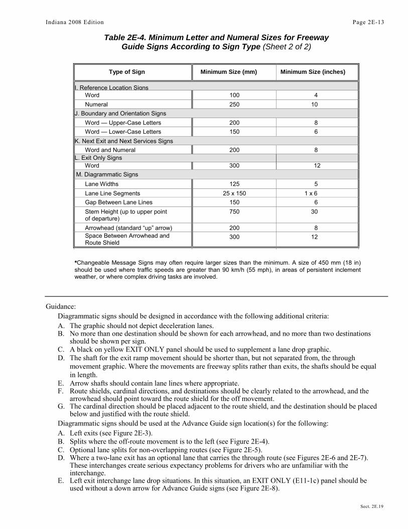
Table 2E-4. Minimum Letter and Numeral Sizes for FreewayGuide Signs According to Sign Type (Sheet 2 of 2)
Type of Sign Minimum Size (mm) Minimum Size (inches)
I. Reference Location SignsWord 100 4Numeral 250 10
J. Boundary and Orientation SignsWord— Upper-Case Letters 200 8Word— Lower-Case Letters 150 6
K. Next Exit and Next Services SignsWord and Numeral 200 8
L. Exit Only SignsWord 300 12
M. Diagrammatic SignsLane Widths 125 5Lane Line Segments 25 x 150 1 x 6Gap Between Lane Lines 150 6Stem Height (up to upper pointof departure)
750 30
Arrowhead (standard “up” arrow) 200 8Space Between Arrowhead andRoute Shield
300 12
*Changeable Message Signs may often require larger sizes than the minimum. A size of 450 mm (18 in)should be used where traffic speeds are greater than 90 km/h (55 mph), in areas of persistent inclementweather, or where complex driving tasks are involved.
Guidance:Diagrammatic signs should be designed in accordance with the following additional criteria:A. The graphic should not depict deceleration lanes.B. No more than one destination should be shown for each arrowhead, and no more than two destinations
should be shown per sign.C. A black on yellow EXIT ONLY panel should be used to supplement a lane drop graphic.D. The shaft for the exit ramp movement should be shorter than, but not separated from, the through
movement graphic. Where the movements are freeway splits rather than exits, the shafts should be equalin length.
E. Arrow shafts should contain lane lines where appropriate.F. Route shields, cardinal directions, and destinations should be clearly related to the arrowhead, and the
arrowhead should point toward the route shield for the off movement.G. The cardinal direction should be placed adjacent to the route shield, and the destination should be placed
below and justified with the route shield.Diagrammatic signs should be used at the Advance Guide sign location(s) for the following:A. Left exits (see Figure 2E-3).B. Splits where the off-route movement is to the left (see Figure 2E-4).C. Optional lane splits for non-overlapping routes (see Figure 2E-5).D. Where a two-lane exit has an optional lane that carries the through route (see Figures 2E-6 and 2E-7).
These interchanges create serious expectancy problems for drivers who are unfamiliar with theinterchange.
E. Left exit interchange lane drop situations. In this situation, an EXIT ONLY (E11-1c) panel should beused without a down arrow for Advance Guide signs (see Figure 2E-8).
Indiana 2008 Edition Page 2E-13
Sect. 2E.19
Figure 2E-3. Diagrammatic Sign for a Single-Lane Left Exit
The upper half of a Left Exit plaque, which contains the word LEFT, may have a blacklegend and border on a yellow background.
Standard:Diagrammatic signs have been shown to be inferior to conventional signs at cloverleaf interchanges and
shall not be used at these locations.Support:
Specific guidelines for more detailed design of diagrammatic signs are contained in the “Standard Highway Signs” book (see Section 1A.11).Section 2E.20 Signing for Interchange Lane DropsStandard:Major guide signs for all lane drops at interchanges shall be mounted overhead. An EXIT ONLY panel shall
be used for all interchange lane drops at which the through route is carried on the mainline.Guidance:
The EXIT ONLY (down arrow) (E11-1) panel (see Figure 2E-9) should be used on all signing of lane dropson all Advance Guide signs for right exits (see Figure 2E-10). For lane drops on the left side, diagrammaticsigning with the EXIT ONLY (E11-1c) panel (see Figure 2E-9) should be used without a down arrow forAdvance Guide signs (see Figure 2E-8).Standard:
The Exit Direction sign (see Figure 2E-20) and E11-1a panel (see Figure 2E-9) shall be of the formatshown in Figures 2E-8 and 2E-10 for all lane drops. The standard slanted up arrow (left side, right side orcentered beneath) shall be included on the Exit Direction sign.Option:
EXIT ONLY messages of either E11-1b or E11-1c formats may be used to retrofit existing signing to warn ofa lane drop situation ahead.
Standard:If used on an existing sign, the E11-1b panel (see Figure 2E-9) shall be placed on either side of a
white down arrow. The E11-1c panel, if used on an existing nondiagrammatic sign, shall be placedbetween the lower destination message and the white down arrow.Guidance:
Wherever the dropped lane carries the through route, diagrammatic signs should be used without the EXITONLY panel.Option:
Advance Guide signs for lane drops within 2 km or 1 mile of the interchange may contain the distance message.
Page 2E-14 Indiana 2008 Edition
Sect. 2E.19 to 2E.20

Figure 2E-4. Diagrammatic Signs for Split with Dedicated Lanes
Indiana 2008 Edition Page 2E-15
Sect. 2E.20
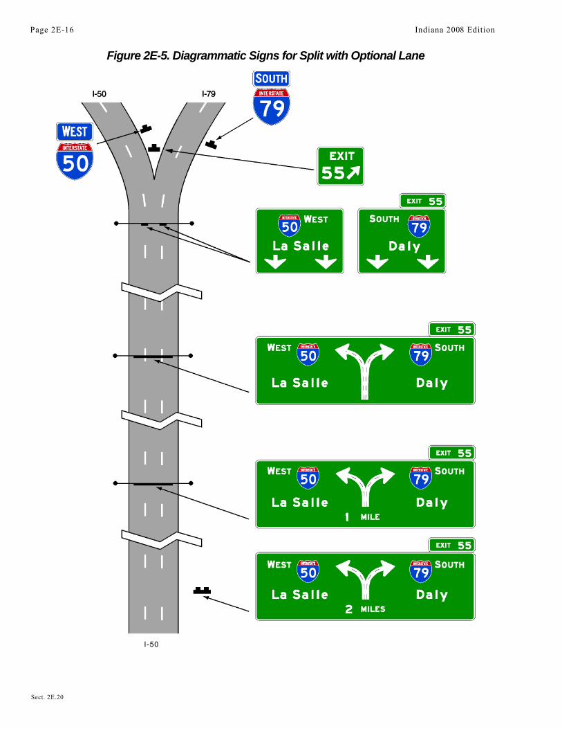
Figure 2E-5. Diagrammatic Signs for Split with Optional Lane
I-50
Page 2E-16 Indiana 2008 Edition
Sect. 2E.20

Figure 2E-6. Diagrammatic Signs for Two-Lane Exit with Optional Lane
Indiana 2008 Edition Page 2E-17
Sect. 2E.20

Figure 2E-7. Diagrammatic Signs for Two-Lane Exit with Optional Lane
Page 2E-18 Indiana 2008 Edition
Sect. 2E.20
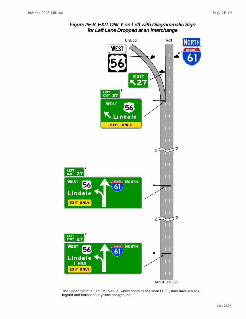
Figure 2E-8. EXIT ONLY on Left with Diagrammatic Signfor Left Lane Dropped at an Interchange
I-61 & U.S. 56
The upper half of a Left Exit plaque, which contains the word LEFT, may have a blacklegend and border on a yellow background.
Indiana 2008 Edition Page 2E-19
Sect. 2E.20

Figure 2E-9. EXIT ONLY Panels
Section 2E.21 Changeable Message SignsStandard:
Changeable message signs shall be capable of displaying several messages in a sequence. Suchmessages shall be changed manually, by remote control, or by automatic controls. Changeable messagesigns shall display pertinent traffic operational and guidance information only, not advertising.Support:
Because technology for changeable message signs continues to advance, a specific standard for changeablemessage signs is not practical. Considerations that influence the selection of the best sign for a particularapplication include conspicuity, legibility, operation, and maintenance of the changeable message sign. ThisSection applies to signs for use on freeway and expressway mainlines. It is recognized that similar signs might beused on ramps and at ramp terminals where smaller letter heights and the number of messages might differ fromthe provisions of this Section.Guidance:
To the extent practical, the design and application of changeable message signs should conform to thegeneral principles of this Manual. Within the context of Section 2A.07, these practices should be followed formainline freeway and expressway applications:
A. Changeable message signs should be capital letters and have a desirable letter size of 450 mm (18 in) or aminimum letter size of 265 mm (10.6 in). Signs should be limited to not more than 3 lines with not morethan 20 characters per line.
B. No more than two displays should be used within any message cycle.C. Each display should convey a single thought.D. The entire message cycle should be readable at least twice by drivers traveling at the posted speed, the
off-peak 85th-percentile speed, or the operating speed.Standard:
Messages shall be centered within each line of legend. If more than one changeable message sign isvisible to road users, then only one such sign shall display a sequential message at any given time.
A three-line changeable message sign shall be limited to not more than two messages. Techniques ofmessage display such as fading, exploding, dissolving, or moving messages shall not be used.
Section 2E.22 Overhead Sign InstallationsSupport:
Specifications for the design and construction of structural supports for highway signs have beenstandardized by the American Association of State Highway and Transportation Officials (AASHTO).Overcrossing structures can often serve for the support of overhead signs, and might in some cases be the onlypractical location that will provide adequate viewing distance. Use of these structures as sign supports willeliminate the need f or additional sign supports along the roadside. Factors justifying the installation of overheadsign
Page 2E-20 Indiana 2008 Edition
Sect. 2E.21 to 2E.22
E11-1aE11-1
E11-1b E11-1c

Figure 2E-10. EXIT ONLY Panels for Right LaneDropped at an Interchange
Indiana 2008 Edition Page 2E-21
Sect. 2E.22

Section 2E.23 Lateral OffsetStandard:
The minimum lateral clearance outside the usable roadway shoulder for ground-mounted freeway andexpressway signs or for overhead sign supports, either to the right or left side of the roadway, shall be 1.8 m (6ft). This minimum clearance shall also apply outside of a barrier curb. If located within the clear zone, thesigns shall be mounted on crashworthy supports or shielded by appropriate crashworthy barriers.Guidance:
Where practical, a sign should not be less than 3 m (10 ft) from the edge of the nearest traffic lane. Largeguide signs especially should be farther removed, preferably 9 m (30 ft) or more from the nearest traffic lane.
Where an expressway median is 3.7 m (12 ft) or less in width, consideration should be given to spanningboth roadways without a center support.
Where overhead sign supports cannot be placed a reasonably safe distance away from the line of traffic or in anotherwise protected site, they should either be designed to minimize the impact forces, or be adequately shieldedby a physical barrier or guardrail of suitable design.Standard:
Butterfly-type sign supports and other overhead noncrashworthy sign supports shall not be installed ingores or other unprotected locations within the clear zone.Option:
Lesser clearances, but not generally less than 1.8 m (6 ft), may be used on connecting roadways or ramps atinterchanges.
Section 2E.24 Guide Sign ClassificationSupport:
Freeway and expressway guide signs are classified and treated in the following categories:A. Route signs and Trailblazer Assemblies (see Section 2E.25);B. At-Grade Intersection signs (see Section 2E.26);C. Interchange signs (see Sections 2E.27 through 2E.36);D. Interchange Sequence signs (see Section 2E.37);E. Community Interchanges Identification signs (see Section 2E.38);F. NEXT X EXITS signs (see Section 2E.39);G. General Service signs (see Section 2E.51);H. Rest and Scenic Area signs (see Section 2E.52);I. Tourist Information and Welcome Center signs (see Section 2E.53);J. Reference Location Signs (see Section 2E.54);K. Miscellaneous guide signs (see Section 2E.55);L. Radio Information signing (see Section 2E.56);M. Carpool and Ridesharing signing (see Section 2E.57);N. Weigh Station signing (see Section 2E.58);O. Specific Service signs (see Chapter 2F); andP. Recreational and Cultural Interest Area signs (see Chapter 2H).
Section 2E.25 Route Signs and Trailblazer AssembliesStandard:
The official Route sign for the Interstate Highway System shall be the red, white, and blueretroreflective distinctive shield adopted by the American Association of State Highway andTransportation Officials (see Section 2D.11).Guidance:
Route signs (see Figure 2E-11) should be incorporated as cut-out shields or other distinctive shapes on largedirectional guide signs. Where the Interstate shield is displayed in an assembly or on the face of a guide sign withU.S. or State Route signs, the Interstate numeral should be at least equal in size to the numerals on the other Routesigns. The use of independent Route signs should be limited primarily to route confirmation assemblies.
Route signs and auxiliary signs showing junctions and turns should be used for guidance on approach roads,for route confirmation just beyond entrances and exits, and for reassurance along the freeway or expressway.When used along the freeway or expressway, the Route signs should be enlarged as shown in the “Standard Highway Signs” book (see Section 1A.11). When independently mounted Route signs are used in place of Pull-Through signs, they should be located just beyond the exit.
Page 2E-22 Indiana 2008 Edition
Sect. 2E.23 to 2E.25

Figure 2E-11. Interstate and U.S. Route Signs
M1-4
Option:The standard Trailblazer Assembly (see Section 2D.32) may be used on roads leading to the freeway or
expressway. Component parts of the Trailblazer Assembly may be included on a single sign panel. Independentlymounted Route signs may be used instead of Pull-Through signs as confirmation information (see Section 2E.11).The commonly used name or trailblazer symbol for a toll facility may be displayed on nontoll sections of theInterstate Highway System at:
A. The last exit before entering a toll section of the Interstate Highway System;B. The interchange or connection with a toll facility, whether or not the toll facility is a part of the Interstate
Highway System; andC. Other locations within a reasonable approach distance of toll facilities when the name or trailblazer
symbol for the toll facility would provide better guidance to road users unfamiliar with the area thanwould place names and route numbers.
The toll facility name or symbol may be included as a part of the guide sign installations on intersectinghighways and approach roads to indicate the interchange with a toll section of an Interstate route. Where needed forthe proper direction of traffic, a trailblazer for a toll facility that is part of the Interstate Highway System may bedisplayed with the Interstate Trailblazer Assembly.
Section 2E.26 Signs for Intersections at GradeGuidance:
If there are intersections at grade within the limits of an expressway, guide sign types specified in Chapter2D should be used. However, such signs should be of a size compatible with the size of other signing on theexpressway.Option:
Advance Guide signs for intersections at grade may take the form of diagrammatic layouts depicting thegeometrics of the intersection along with essential directional information.
Section 2E.27 Interchange Guide SignsStandard:
The signs at interchanges and on their approaches shall include Advance Guide signs and ExitDirection signs. Consistent destination messages shall be displayed on these signs.Guidance:
New destination information should not be introduced into the major sign sequence for one interchange, norshould destination information be dropped.
Indiana 2008 Edition Page 2E-23
Sect. 2E.25 to 2E.27
EISENHOWER INTERSTATE SYSTEM
OR

Reference should be made to Section 2E.10 and Sections 2E.30 through 2E.39 for a detailed description ofthe signs in the order that they should appear at the approach to and beyond each interchange. Guide signs placedin advance of an interchange deceleration lane should be spaced at least 245 m (800 ft) apart.
Supplemental guide signing should be used sparingly as provided in Section 2E.32.Section 2E.28 Interchange Exit NumberingSupport:
Interchange exit numbering provides valuable orientation for the road user on a freeway or expressway. Thefeasibility of numbering interchanges or exits on an expressway will depend largely on the extent to which gradeseparations are provided. Where there is appreciable continuity of interchange facilities, interrupted only by anoccasional intersection at grade, the numbering will be helpful to the expressway user.Standard:
Interchange numbering shall be used in signing each freeway interchange exit. Interchange exitnumbers shall be displayed with each Advance Guide sign, Exit Direction sign, and Gore sign. The exitnumber shall be displayed on a separate plaque at the top of the Advance Guide or Exit Direction sign. Thestandard exit number plaque shall include the word EXIT, the appropriate exit number, and the suffixletter (on multi-exit interchanges) separated from the exit number by a space in a single-line format on aplaque750 mm (30 in) in height. Exit numbers shall not include the cardinal initials corresponding to thedirections of the cross route. Minimum numeral and letter sizes are given in Tables 2E-1 through 2E-4. Ifused, the interchange numbering system for expressways shall conform to the provisions prescribed forfreeways.Option:
There are two approaches to interchange exit numbering that the State and local highway agencies may use:(1) reference location sign numbering or (2) consecutive numbering.Support:
Reference location sign exit numbering is preferred over consecutive exit numbering for two reasons: (1) ifnew interchanges are added to a route, the highway agencies do not have to change the numbering sequence; and(2) reference location sign numbering assists road users in determining their destination distances and travelmileage.
Exit numbers may also be used with Supplemental Guide signs and Road User Service signs.Guidance:
Exit number plaques should be located toward the top left edge of the sign for a left exit and toward the topright edge for right exits.
Because road users might not expect a left exit and might have difficulty in maneuvering to the left, the wordLEFT should be added to the exit number plaque (see Figure 2E-3). Where a left exit is not numbered (no exitnumber plaque), a plaque with the word LEFT should be added to the top left edge of the sign.Option:
The portion of the exit number plaque containing the word LEFT may have a black legend and border on ayellow background.Support:
The general plan for numbering interchange exits is shown in Figures 2E-12 through 2E-14.Example exit number plaque designs are shown in Figures 2E-3 and 2E-15. Figures 2E-1, 2E-20, 2E-23,
2E-27 through 2E-32, and 2E-42 illustrate the incorporation of exit number plaques on guide signs.Standard:
Where a route originates within a State, the southernmost or westernmost terminus shall be thebeginning point for numbering. If a loop, spur, or circumferential route crosses State boundaries, thesequence of numbering shall be coordinated by the States to provide continuous numbering.
For circumferential routes, the numbering of interchanges shall be in a clockwise direction. Thenumbering shall begin with the first interchange west of the south end of an imaginary north-south linebisecting the circumferential route, at a radial freeway or other Interstate route, or some other conspicuouslandmark in the circumferential route near a south polar location (see Figure 2E-12). The interchangenumbers on loop routes shall begin at the loop interchange nearest the south or west mainline junction andincrease in magnitude toward the north or east mainline junction (see Figure 2E-13). Spur routeinterchanges shall be numbered in ascending order starting at the interchange where the spur leaves themainline of the principal route (see Figure 2E-13).
Page 2E-24 Indiana 2008 Edition
Sect. 2E.27 to 2E.28

Figure 2E-12. Example of Interchange Numbering for Mainlineand Circumferential Routes
Indiana 2008 Edition Page 2E-25
Sect. 2E.28

Figure 2E-13. Example of Interchange Numbering forMainline, Loop, and Spur Routes
Page 2E-26 Indiana 2008 Edition
Sect. 2E.28
Where numbered routes overlap, continuity of interchange numbering shall be established for only one ofthe routes (see Figure 2E-14). If one of the routes is an Interstate, the Interstate route shall maintaincontinuity of interchange numbering.Guidance:
The route chosen for continuity of interchange numbering should also have reference location sign continuity(see Figure 2E-14).
Section 2E.29 Interchange ClassificationSupport:
For signing purposes, interchanges are classified as major, intermediate, and minor. The minimum alphabetsizes contained in Tables 2E-1 and 2E-3 are based on this classification. Descriptions of these classifications are asfollows:
A. Major interchanges are subdivided into two categories: (a) interchanges with other expressways orfreeways, or (b) interchanges with high-volume multi-lane highways, principal urban arterials, or majorrural routes where the volume of interchanging traffic is heavy or includes many road users unfamiliarwith the area.
B. Intermediate interchanges are those with urban and rural routes not in the category of major or minorinterchanges.
C. Minor interchanges include those where traffic is local and very light, such as interchanges with landservice access roads. Where the sum of exit volumes is estimated to be lower than 100 vehicles per day inthe design year, the interchange is classified as minor.
Section 2E.30 Advance Guide SignsSupport:
The Advance Guide sign gives notice well in advance of the exit point of the principal destinations served bythe next interchange and the distance to that interchange (see Figure 2E-15).Guidance:
For major and intermediate interchanges (see Section 2E.29), Advance Guide signs should be placed at 1 km or0.5 miles and at 2 km or 1 mile in advance of the exit with a third Advance Guide sign placed at 4 km (2 mi) inadvance of the exit if spacing permits. At minor interchanges, only one Advance Guide sign should be used.It should be located 1 to 2 km or 0.5 to 1 mile from the exit gore. If the sign is located less than 1 km or 0.5 milesfrom the exit, the distance shown should be to the nearest 400 m or 1/4 mile. Fractions of kilometers or decimals ofkilometers should not be used. Fractions of a mile, rather than decimals, should be shown in all cases.
Where Advance Guide signs are provided for a left exit, diagrammatic signs should be used (see Figure 2E-3).Standard:
When used, Advance Guide signs shall contain the distance message. The legend on the AdvanceGuide signs shall be the same as the legend on the Exit Direction sign, except that the last line shall readEXIT X km (EXIT X MILES). If the interchange has two or more exit roadways, the bottom line shallread EXITS X km (EXITS X MILES).Option:
Where interchange exit numbers are used, the word EXIT may be omitted from the bottom line. Where thedistance between interchanges is more than 2 km or 1 mile, but less than 4 km or 2 miles, the first Advance Guidesign may be closer than 4 km or 2 miles, but not placed so as to overlap the signing for the previous exit. DuplicateAdvance Guide signs or Interchange Sequence Series signs may be placed in the median on the opposite side ofthe roadway and are not included in the minimum requirements of interchange signing.Guidance:
Where there is less than 245 m (800 ft) between interchanges, Interchange Sequence Series signs should beused instead of Advance Guide signs for the affected interchanges.
Section 2E.31 Next Exit Supplemental SignsOption:
Where the distance to the next interchange is unusually long, Next Exit supplemental signs may be installed toinform road users of the distance to the next interchange (see Figure 2E-16).Guidance:
The Next Exit supplemental sign should not be used unless the distance between successive interchanges ismore than 8 km (5 mi).
Indiana 2008 Edition Page 2E-27
Sect. 2E.28 to 2E.31

Figure 2E-14. Example of Interchange Numbering If Routes Overlap
Page 2E-28 Indiana 2008 Edition
Sect. 2E.31
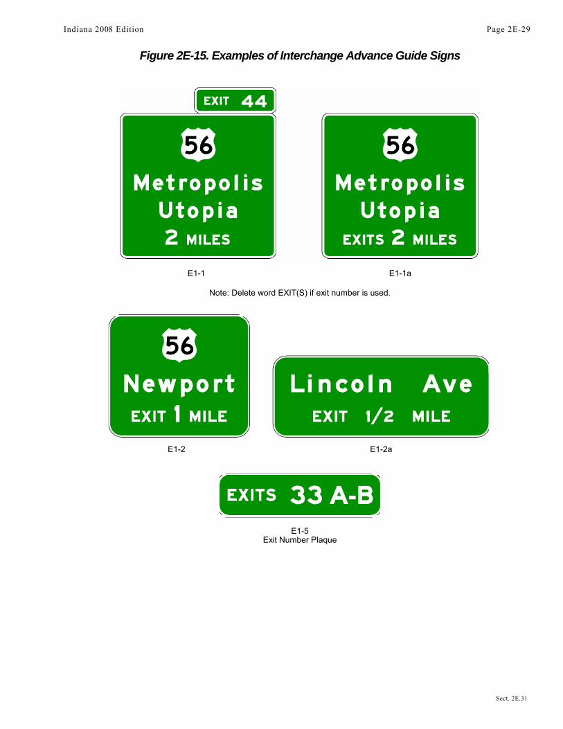
Figure 2E-15. Examples of Interchange Advance Guide Signs
E1-1 E1-1a
Note: Delete word EXIT(S) if exit number is used.
E1-2 E1-2a
E1-5Exit Number Plaque
Indiana 2008 Edition Page 2E-29
Sect. 2E.31

Figure 2E-16. Next Exit Supplemental Advance Guide Signs
E2-1
E2-1 A
Standard:The Next Exit supplemental sign shall carry the legend NEXT EXIT X km (X MILES). If the Next Exit
supplemental sign is used, it shall be placed below the Advance Guide sign nearest the interchange. It shallbe mounted so as to not adversely affect the breakaway feature of the sign support structure.Option:
The legend for the Next Exit supplemental sign may be displayed in either one or two lines. The one-linemessage is the more desirable choice unless the message causes the sign to have a horizontal dimension greaterthan that of the Advance Guide sign.
Section 2E.32 Other Supplemental Guide SignsSupport:
Supplemental Guide signs can be used to provide information regarding destinations accessible from aninterchange, other than places shown on the standard interchange signing. However, such Supplemental Guidesigning can reduce the effectiveness of other more important guide signing because of the possibility ofoverloading the road user's capacity to receive visual messages and make appropriate decisions. “The AASHTO Guidelines for the Selection of Supplemental Guide Signs for Traffic Generators Adjacent to Freeways” is incorporated by reference in this section (see Page i for AASHTO’s address).Guidance:
No more than one Supplemental Guide sign should be used on each interchange approach. Supplemental Guidesigns should not be used at freeway to freeway interchanges.
A Supplemental Guide sign (see Figure 2E-17) should not list more than two destinations. Destinationnames should be followed by the interchange number (and suffix), or if interchanges are not numbered, by thelegend NEXT RIGHT or SECOND RIGHT or both, as appropriate. The Supplemental Guide sign should beinstalled as an independent guide sign assembly.
Where two or more Advance Guide signs are used, the Supplemental Guide sign should be installedapproximately midway between two of the Advance Guide signs, where possible. Otherwise the SupplementalGuide sign should be installed 290 m (1600 ft) in advance of the beginning of the deceleration lane. If only oneAdvance Guide sign is used, the Supplemental Guide sign should follow it by at least 245 m (800 feet). If theinterchanges are numbered, the interchange number should be used for the action message.States and other agencies should adopt an appropriate policy for installing supplemental signs using “The
AASHTO Guidelines for the Selection of Supplemental Guide Signs for Traffic Generators Adjacent toFreeways.” In developing policies for such signing, such items as population, amount of traffic generated,distance from the route, and the significance of the destination should be taken into account.Standard:
Guide signs directing drivers to park and ride facilities shall be considered as Supplemental Guidesigns (see Figures 2E-18 and 2E-19).Sect. 2E.31 to 2E.32
Page 2E-30 Indiana 2008 Edition
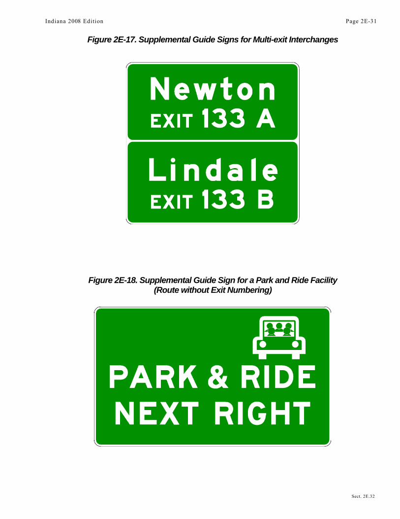
Figure 2E-17. Supplemental Guide Signs for Multi-exit Interchanges
Figure 2E-18. Supplemental Guide Sign for a Park and Ride Facility(Route without Exit Numbering)
Indiana 2008 Edition Page 2E-31
Sect. 2E.32

Figure 2E-19. Supplemental Guide Sign for a Park and Ride Facility(Route with Exit Numbering)
Figure 2E-20. Interchange Exit Direction Sign
Page 2E-32 Indiana 2008 Edition
Sect. 2E.32

Section 2E.33 Exit Direction SignsSupport:
The Exit Direction sign repeats the route and destination information that was shown on the Advance Guidesign(s) for the next exit, and thereby assures road users of the destination served and indicates whether they exit tothe right or the left for that destination.Standard:
Exit Direction signs (see Figure 2E-20) shall be used at major and intermediate interchanges.Population figures or other similar information shall not be used on Exit Direction signs.Guidance:
Exit Direction signs should be used at minor interchanges.Ground-mounted Exit Direction signs should be installed at the beginning of the deceleration lane. If there is
less than 90 m (300 ft) from the beginning of the deceleration lane to the theoretical gore (see Figure 3B-8), the ExitDirection sign should be installed overhead over the exiting lane in the vicinity of the theoretical gore.Standard:
Where a through lane is being terminated (dropped) at an exit, the Exit Direction sign shall be placedoverhead at the theoretical gore (see Figures 2E-8 and 2E-10).
The following provisions shall govern the design and application of the overhead Exit Direction sign:A. The sign shall carry the exit number (if used), the route number, cardinal direction, and
destination with an appropriate upward slanting arrow (see Figure 2E-20).B. The message EXIT ONLY in black on a yellow panel shall be used on the overhead Exit Direction
sign to advise road users of a lane drop situation. The sign shall conform to the provisions ofSection 2E.20.
C. Diagrammatic signs shall not be employed at the exit direction location.Guidance:
Exit number plaques should be located toward the left edge of the sign for a left exit and toward the rightedge for right exits.Option:
In some cases, principally in urban areas, where restricted sight distance because of structures or unusualalignment make it impossible to locate the Exit Direction sign without violating the required minimum spacing(see Section 2E.30) between major guide signs, Interchange Sequence signs (see Section 2E.37) may besubstituted for an Advance Guide sign.Guidance:
At multi-exit interchanges, the Exit Direction sign should be located directly over the exiting lane for the firstexit. At the same location, and normally over the right through lane, an Advance Guide sign for the second exitshould be located. Only for those conditions where the through movement is not evident should a confirmatorymessage (Pull-Through sign as shown in Figure 2E-2) be used over the left lane(s) to guide road users travelingthrough an interchange. In the interest of sign spreading, three signs on one structure should not be used. When thefreeway or expressway is on an overpass, the Exit Direction sign should be installed on an overhead support over theexit lane in advance of the gore point.Option:
If the second exit is beyond an underpass, the Exit Direction sign may be mounted on the face of theoverhead structure.
Section 2E.34 Exit Gore SignsSupport:
The Exit Gore sign in the gore indicates the exiting point or the place of departure from the main roadway.Consistent application of this sign at each exit is important.Standard:
The gore shall be defined as the area located between the main roadway and the ramp just beyondwhere the ramp branches from the main roadway. The Exit Gore sign shall be located in the gore andshall carry the word EXIT or EXIT XX (if interchange numbering is used) and an appropriate upwardslanting arrow (see Figure 2E-21). Breakaway or yielding supports shall be used.
Indiana 2008 Edition Page 2E-33
Sect. 2E.33 to 2E.34
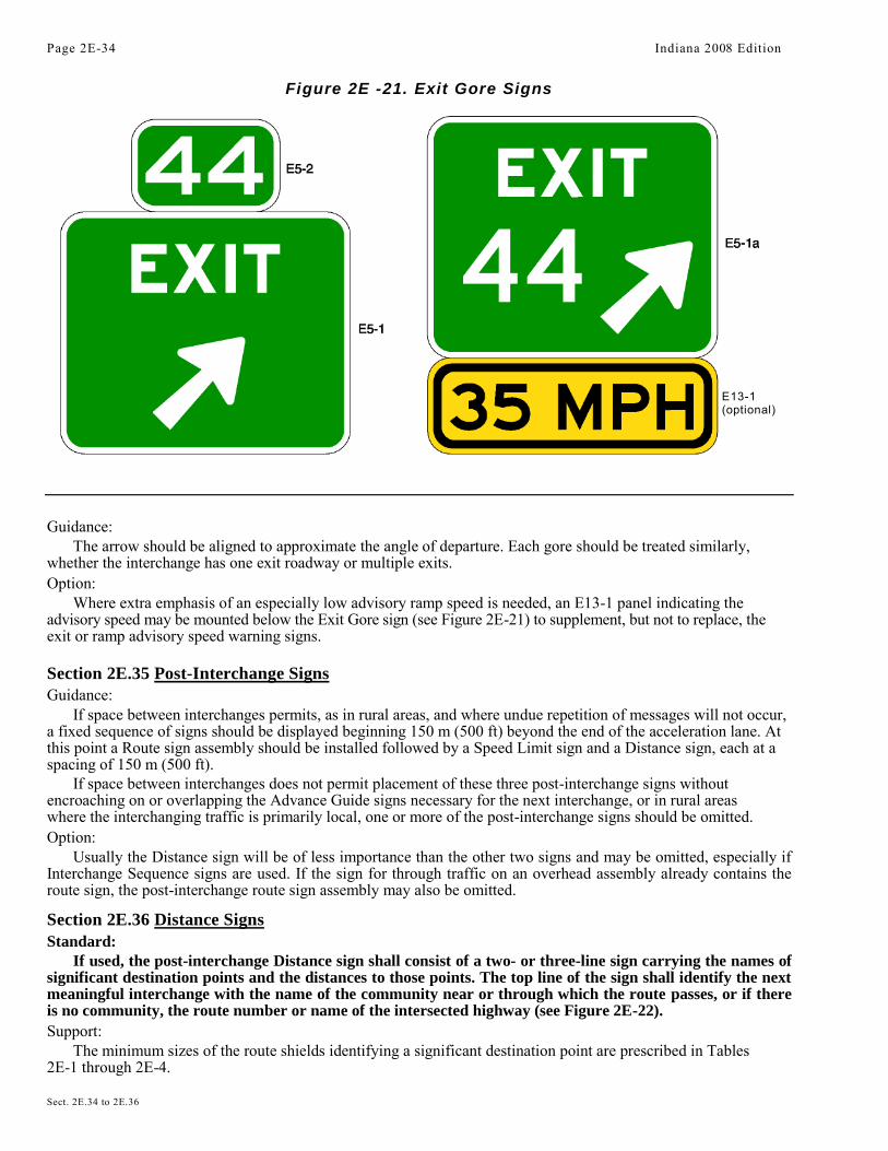
Figure 2E -21. Exit Gore Signs
Guidance:The arrow should be aligned to approximate the angle of departure. Each gore should be treated similarly,
whether the interchange has one exit roadway or multiple exits.Option:
Where extra emphasis of an especially low advisory ramp speed is needed, an E13-1 panel indicating theadvisory speed may be mounted below the Exit Gore sign (see Figure 2E-21) to supplement, but not to replace, theexit or ramp advisory speed warning signs.
Section 2E.35 Post-Interchange SignsGuidance:
If space between interchanges permits, as in rural areas, and where undue repetition of messages will not occur,a fixed sequence of signs should be displayed beginning 150 m (500 ft) beyond the end of the acceleration lane. Atthis point a Route sign assembly should be installed followed by a Speed Limit sign and a Distance sign, each at aspacing of 150 m (500 ft).
If space between interchanges does not permit placement of these three post-interchange signs withoutencroaching on or overlapping the Advance Guide signs necessary for the next interchange, or in rural areaswhere the interchanging traffic is primarily local, one or more of the post-interchange signs should be omitted.Option:
Usually the Distance sign will be of less importance than the other two signs and may be omitted, especially ifInterchange Sequence signs are used. If the sign for through traffic on an overhead assembly already contains theroute sign, the post-interchange route sign assembly may also be omitted.
Section 2E.36 Distance SignsStandard:
If used, the post-interchange Distance sign shall consist of a two- or three-line sign carrying the names ofsignificant destination points and the distances to those points. The top line of the sign shall identify the nextmeaningful interchange with the name of the community near or through which the route passes, or if thereis no community, the route number or name of the intersected highway (see Figure 2E-22).Support:
The minimum sizes of the route shields identifying a significant destination point are prescribed in Tables2E-1 through 2E-4.
Page 2E-34 Indiana 2008 Edition
Sect. 2E.34 to 2E.36
E13-1(optional)

Figure 2E-22. Post-Interchange Distance Sign
Option:The text identification of a route may be shown instead of a route shield, such as "US XX", "State Route
XX", or "County Route X”.Guidance:
If a second line is used, it should be reserved for communities of general interest that are located on orimmediately adjacent to the route or for major traffic generators along the route.Option:
The choice of names for the second line, if it is used, may be varied on successive Distance signs to giveroad users maximum information concerning communities served by the route.Standard:
The third, or bottom line, shall contain the name and distance to a control city (if any) that hasnational significance for travelers using the route.Guidance:
Distances to the same destinations should not be shown more frequently than at 8 km (5 mi) intervals. Thedistances displayed on these signs should be the actual distance to the destination points and not to the exit fromthe freeway or expressway.
Section 2E.37 Interchange Sequence SignsGuidance:
If there is less than 245 m (800 ft) between interchanges, Interchange Sequence signs should be used instead ofthe Advance Guide signs for the affected interchanges. If used, Interchange Sequence signs should be used over theentire length of a route in an urban area. They should not be used on a single interchange basis.Option:
If interchanges are closely spaced, particularly through large urban areas, so that guide signs cannot beadequately spaced, Interchange Sequence signs identifying the next two or three interchanges may be used.Support:
Interchange Sequence signs are generally supplemental to Advance Guide signs. Signing of this type isillustrated in Figures 2E-23 and 2E-24, and is compatible with the sign spreading concept.
These signs are installed in a series and display the next two or three interchanges by name or route numberwith distances to the nearest 400 m or 1/4 mile.Standard:
If used, the first sign in the series shall be located in advance of the first Advance Guide sign for thefirst interchange.
Where the exit direction is to the left, interchange names or route numbers shown on such signs shallbe followed by the legend LEFT or LEFT EXIT in black letters on a yellow rectangular background.
Indiana 2008 Edition Page 2E-35
Sect. 2E.36 to 2E.37
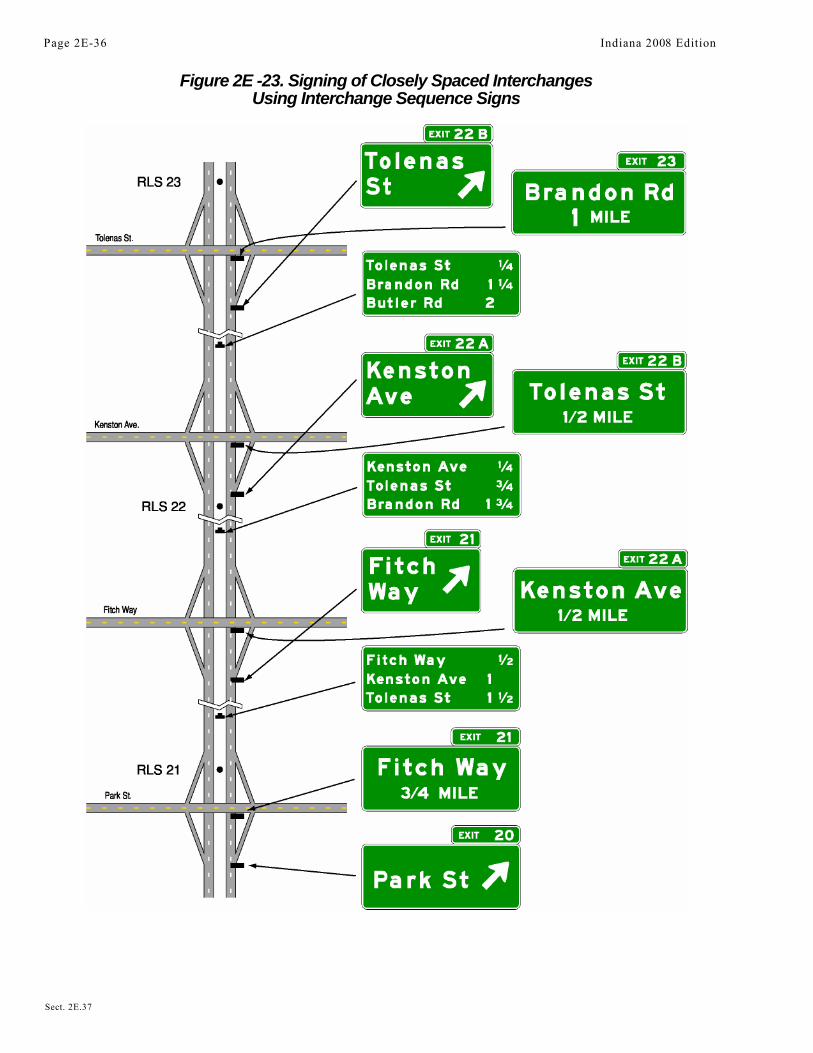
Figure 2E -23. Signing of Closely Spaced InterchangesUsing Interchange Sequence Signs
Page 2E-36 Indiana 2008 Edition
Sect. 2E.37
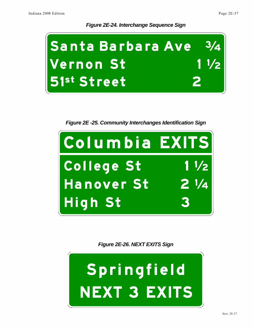
Figure 2E-24. Interchange Sequence Sign
Figure 2E -25. Community Interchanges Identification Sign
Figure 2E-26. NEXT EXITS Sign
Indiana 2008 Edition Page 2E-37
Sect. 2E.37

Interchange Sequence signs shall not be substituted for Exit Direction signs.Guidance:
Interchange Sequence signs should be located in the median. After the first of the series, InterchangeSequence signs should be placed approximately midway between interchanges.Standard:
Interchange Sequence signs located in the median shall be installed at overhead sign height.Option:
Interchange numbers may be shown to the left of the interchange name or route number.
Section 2E.38 Community Interchanges Identification SignsSupport:
For suburban or rural communities served by two or three interchanges, Community InterchangesIdentification signs are useful (see Figure 2E-25).Guidance:
In these cases, the name of the community followed by the word EXITS should be shown on the top line; thelines below should display the destination, road name or route number, and the corresponding distances to thenearest 400 m or 1/4 mile.
The sign should be located in advance of the first Advance Guide sign for the first interchange within thecommunity.Option:
If interchanges are not conveniently identifiable or if there are more than three interchanges to be identified,the NEXT X EXITS sign (see Section 2E.39) may be used.
Section 2E.39 NEXT X EXITS SignSupport:
Many freeways or expressways pass through historical or recreational regions, or urban areas served by asuccession of several interchanges.Option:
Such regions or areas may be indicated by a NEXT X EXITS sign (see Figure 2E-26) located in advance ofthe Advance Guide sign or signs for the first interchange.Guidance:
The sign legend should identify the region or area followed by the words NEXT X EXITS.
Section 2E.40 Signing by Type of InterchangeSupport:
Road users need signs to help identify the location of the exit, as well as to obtain route, direction, anddestination information for specific exit ramps. Figures 2E-27 through 2E-32 show examples of guide signs forcommon types of interchanges. The interchange layouts shown in most of the figures illustrate only the majorguide signs for one direction of traffic on the through road and on the crossroad.Standard:
Interchange guide signing shall be consistent for each type of interchange along a route.Guidance:
The signing layout for all interchanges having only one exit ramp in the direction of travel should be similar,regardless of the interchange type (see Figures 2E-8, 2E-10, and Figures 2E-27 through 2E-32). For the sake ofuniform application, the significant features of the signing plan for each of the more frequent kinds of interchanges(illustrated in Figures 2E-27 through 2E-32) should be followed as closely as possible. Even when unusualgeometric features exist, variations in signing layout should be held to a minimum.
Section 2E.41 Freeway-to-Freeway InterchangeSupport:
Freeway-to-freeway interchanges are major decision points where the effect of taking a wrong ramp cannotbe easily corrected. Reversing direction on the connecting freeway or reentering to continue on the intendedcourse is usually not possible. Figure 2E-27 shows examples of guide signs at a freeway-to-freeway interchange.
Page 2E-38 Indiana 2008 Edition
Sect. 2E.37 to 2E.41

Figure 2E-27. Examples of Freeway-to-Freeway Interchange Guide Signs
Indiana 2008 Edition Page 2E-39
Sect. 2E.41

Figure 2E-28. Examples of Guide Signs for Ful Cloverleaf Interchange
Note: See Figure 2E-38 for examples of multi-lane crossroad signing for cloverleaf interchanges
Page 2E-40 Indian 2008 Edition
Sect. 2E.41
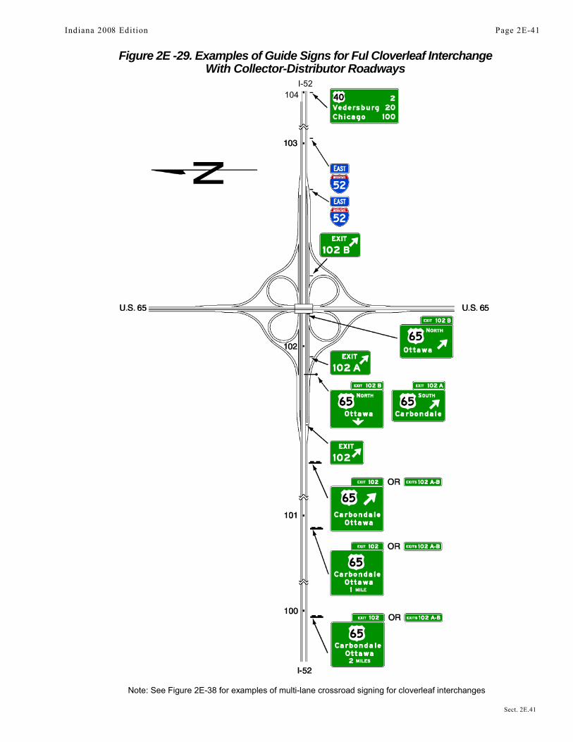
Figure 2E -29. Examples of Guide Signs for Ful Cloverleaf InterchangeWith Collector-Distributor Roadways
I-52
Note: See Figure 2E-38 for examples of multi-lane crossroad signing for cloverleaf interchanges
Indiana 2008 Edition Page 2E-41
Sect. 2E.41
104

Figure 2E-30. Examples of Partial Cloverleaf Interchange Guide Signs
Note: See Figure 2E-37 for examples of multi-lane crossroad signing for partial cloverleaf interchanges
Page 2E-42 Indiana 2008 Edition
Sect. 2E.41
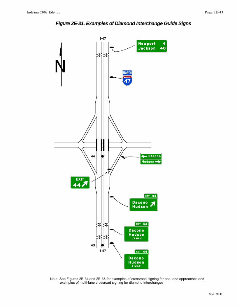
Figure 2E-31. Examples of Diamond Interchange Guide Signs
Note: See Figures 2E-34 and 2E-36 for examples of crossroad signing for one-lane approaches andexamples of multi-lane crossroad signing for diamond interchanges
Indiana 2008 Edition Page 2E-43
Sect. 2E.41

Figure 2E-32. Examples of Diamond Interchange Guide Signs in an Urban Area
Note: See Figures 2E-34 and 2E-36 for examples of crossroad signing for one-lane approaches andexamples of multi-lane crossroad signing for diamond interchanges
Page 2E-44 Indiana 2008 Edition
Sect. 2E.41

Guidance:The sign messages should contain only the route shield, cardinal direction, and the name of the next control city
on the route. Arrows should point as indicated in Section 2D.08, unless a diagrammatic representation of theinterchange layout requires otherwise.
At splits where the off-route movement is to the left or where there is an optional lane split, expectancyproblems usually result, and diagrammatic signs should be used at the Advance Guide sign location.Diagrammatic signs (see Section 2E.19) also should be used at the Advance Guide sign locations forinterchanges where two-lane exits with an optional lane carry the through route on the exiting lanes.Standard:
Overhead signs shall be used at a distance of 2 km or 1 mile and at the theoretical gore of eachconnecting ramp. When diagrammatic signs are used, they shall conform to the provisions of Section2E.19.Option:
Overhead signs may also be used at the 1 km or 0.5 mile and 4 km or 2 mile points.The arrow and/or the name of the control city may be omitted on signs that indicate the straight-ahead
continuation of a route.An Exit Speed sign may be used where an engineering study shows that it is necessary to display a speed
reduction message for ramp signing (see Section 2C.36).
Section 2E.42 Cloverleaf InterchangeSupport:
A cloverleaf interchange has two exits for each direction of travel. The exits are closely spaced and have commonAdvance Guide signs. Examples of guide signs for cloverleaf interchanges are shown in Figure 2E-28.
Guidance:The Advance Guide signs should include two place names, one corresponding to each exit ramp, with the
name of the place served by the first exit on the upper line.Standard:
An Overhead Guide sign shall be placed at the theoretical gore point of the first exit ramp, with anupward slanting arrow on the exit direction sign for that exit and the message XX km (XX MILE) on theAdvance Guide sign for the second exit, as shown in Figure 2E-28. The second exit shall be indicated by anoverhead Exit Direction sign over the auxiliary lane. An Exit sign shall also be used at each gore (seeSection 2E.34).
Interchanges with more than one exit from the main line shall be numbered as described in Section2E.28 with an appropriate suffix.
Diagrammatic signs shall not be used for cloverleaf interchanges.Guidance:
As shown in Figure 2E-28, the overhead Exit Direction sign for the second exit should be mounted on thestructure if the mainline passes under the crossroad and the exit roadway is located beyond the structure.
Section 2E.43 Cloverleaf Interchange with Collector-Distributor RoadwaysSupport:
Examples of guide signs for full cloverleaf interchanges with collector-distributor roadways are shown inFigure 2E-29.Guidance:
Signing on the collector-distributor roadways should be the same as the signing on the mainline of acloverleaf interchange.Standard:
Guide signs at exits from the collector-distributor roadways shall be overhead and located at thetheoretical gore of the collector-distributor roadway and the exit ramp.Option:
Exits from the collector-distributor roadways may be numbered with an appropriate suffix. The AdvanceGuide signs may include two place names and their corresponding exit numbers or may use the singular EXIT.
Indiana 2008 Edition Page 2E-45
Sect. 2E.41 to 2E.43

Section 2E.44 Partial Cloverleaf InterchangeSupport:
Examples of guide signs for partial cloverleaf interchanges are shown in Figure 2E-30.Guidance:
As shown in Figure 2E-30, the overhead Exit Direction sign should be placed on the structure if the mainlinepasses under the crossroad and the exit roadway is located beyond the structure.Standard:
A ground-mounted Exit Gore sign shall also be installed in the ramp gore.
Section 2E.45 Diamond InterchangeSupport:
Examples of guide signs for diamond interchanges are shown in Figure 2E-31.Standard:
The singular message EXIT shall be used on the Advance Guide and Exit Direction signs. Exitnumbers shall not include the cardinal initials corresponding to the direction of the cross route.Support:
The typical diamond interchange ramp departs from the mainline roadway such that a speed reduction generallyis not necessary in order for a driver to reasonably safely negotiate an exit maneuver from the mainline onto theramp roadway.Guidance:
When a speed reduction is not necessary, an exit speed sign should not be used.Option:
An Exit Speed sign may be used where an engineering study shows that it is necessary to display a speedreduction message for ramp signing (see Section 2C.36).Guidance:
The Exit Speed sign should be located along the deceleration lane or along the ramp such that it is visible tothe driver far enough in advance so that a reasonably safe slowing and exiting maneuver can be made.Option:
A Stop Ahead or Signal Ahead warning sign may be placed, where engineering judgment indicates a need,along the ramp in advance of the cross street, to give notice to the driver (see Section 2C.29).Guidance:
When used on two-lane ramps, Stop Ahead or Signal Ahead signs should be used in pairs with one sign oneach side of the ramp.
Section 2E.46 Diamond Interchange in Urban AreaSupport:
Examples of guide signs for diamond interchanges in an urban area are shown in Figure 2E-32. This exampleincludes the use of the Community Interchanges Identification sign (see Section 2E.38) which might be useful iftwo or more interchanges serve the same community.
In urban areas, street names are often shown as the principal message in destination signs.Option:
If interchanges are too closely spaced to properly locate the Advance Guide signs, they may be placed closer tothe exit, and the distance figures adjusted accordingly.
Section 2E.47 Closely Spaced InterchangesOption:
When a series of interchanges is closely spaced, the advance guide sign for the next interchange may bemounted on an overhead structure located downstream from the gore of the preceding interchange.Guidance:
Interchange Sequence signs should be used at closely spaced interchanges. When used, they should identifyand show street names and distances for the next two or three exits as shown in Figure 2E-23.Standard:
Advance Guide signs for closely spaced interchanges shall show information for only one interchange.Sect. 2E.44 to 2E.47
Page 2E-46 Indiana 2008 Edition
Section 2E.48 Minor InterchangeOption:
Less signing may be used for minor interchanges because such interchanges customarily serve low volumes oflocal traffic.Support:
Examples of guide signs for minor interchanges are shown in Figure 2E-33.Standard:
At least one Advance Guide sign and an Exit Gore sign shall be placed at a minor interchange.Guidance:
An Exit Direction sign should also be used.
Section 2E.49 Signing of Approaches and Connecting RoadwaysSupport:
Because there are a number of different ramp configurations that are commonly used at interchanges withconventional roads, drivers on the conventional road cannot reliably predict whether they will be required to turnleft or right in order to enter the correct ramp to access the freeway or expressway in the desired direction of travel.Consistently applied signing for conventional road approaches to freeway or expressway interchanges is highlydesirable.Guidance:
The signing of conventional roads with one lane of traffic approaching an interchange should consist of asequence containing the following signs (see Figure 2E-34):
A. Junction AssemblyB. Destination signC. Directional Assembly or Entrance Direction sign for the first rampD. Advance Route Turn Assembly or Advance Entrance Direction sign with an advance turn arrowE. Directional Assembly or Entrance Direction sign for the second ramp
Standard:If used, the Entrance Direction sign shall consist of a white legend and border on a green background. It
shall contain the freeway or expressway route shield(s), cardinal direction, and directional arrow(s).Option:
The Entrance Direction sign may contain a destination(s) and/or an action message such as NEXT RIGHT. Atminor interchanges, the following sequence of signs may be used (see Figure 2E-35):A. Junction AssemblyB. Directional Assembly for the first rampC. Directional Assembly for the second ramp
Guidance:On multi-lane conventional roads approaching an interchange, the sign sequence should contain the
following signs (see Figures 2E-36, 2E-37, and 2E-38):A. Junction AssemblyB. Advance Entrance Direction sign(s) for both directions (if applicable) of travel on the freeway
or expresswayC. Entrance Direction sign for first rampD. Advance Turn AssemblyE. Entrance Direction sign for the second ramp
Support:Advance Entrance signs are used to direct road users to the appropriate lane(s).
Standard:The Advance Entrance sign shall consist of a white legend and border on a green background. It shall
contain the freeway or expressway route shield(s) and cardinal direction(s).Option:
The Advance Entrance sign may have destinations, directional arrows, and/or an action message such as LEFTLANE, NEXT LEFT, or SECOND RIGHT. Signs in this sequence may be mounted overhead to improvevisibility.
Indiana 2008 Edition Page 2E-47
Sect. 2E.48 to 2E.49

Figure 2E-33. Examples of Minor Interchange Guide Signs
Note: See Figure 2E-35 for example of minor interchange crossroad signing
Page 2E-48 Indiana 2008 Edition
Sect. 2E.49
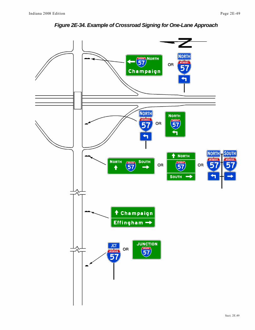
Figure 2E-34. Example of Crossroad Signing for One-Lane Approach
Indiana 2008 Edition Page 2E-49
Sect. 2E.49
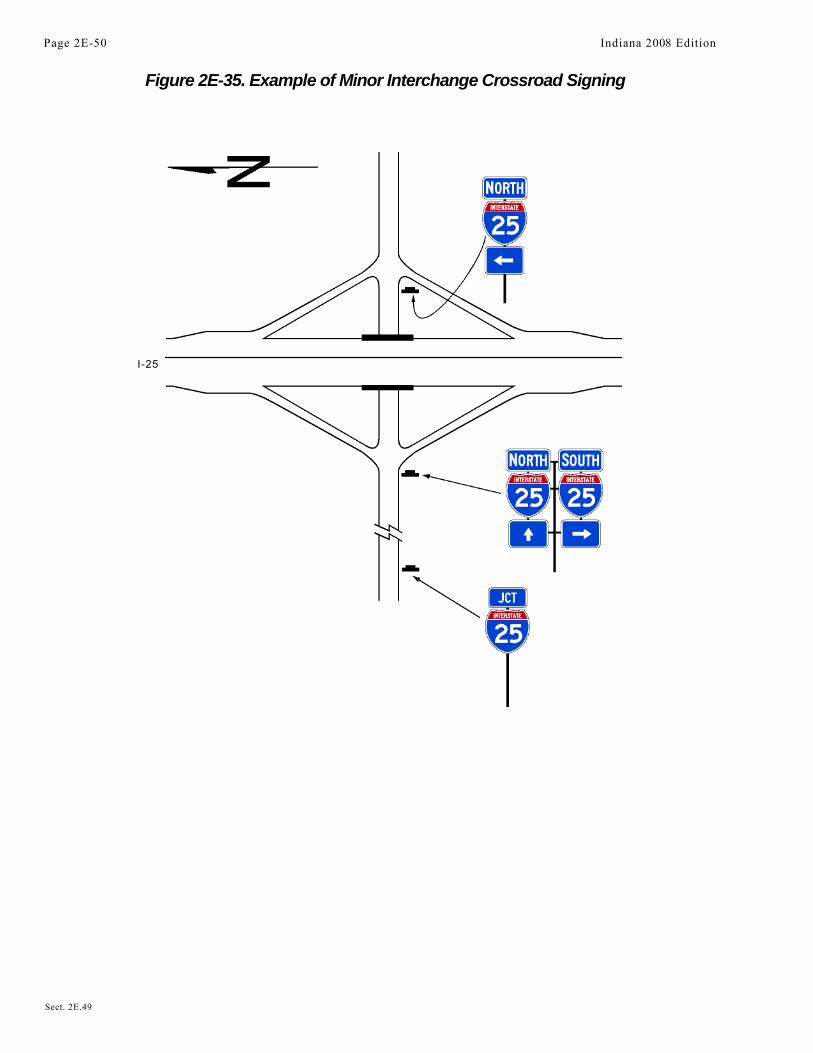
Figure 2E-35. Example of Minor Interchange Crossroad Signing
I-25
Page 2E-50 Indiana 2008 Edition
Sect. 2E.49

Figure 2E-36. Examples of Multi-lane Crossroad Signingfor Diamond Interchange
Indiana 2008 Edition Page 2E-51
Sect. 2E.49
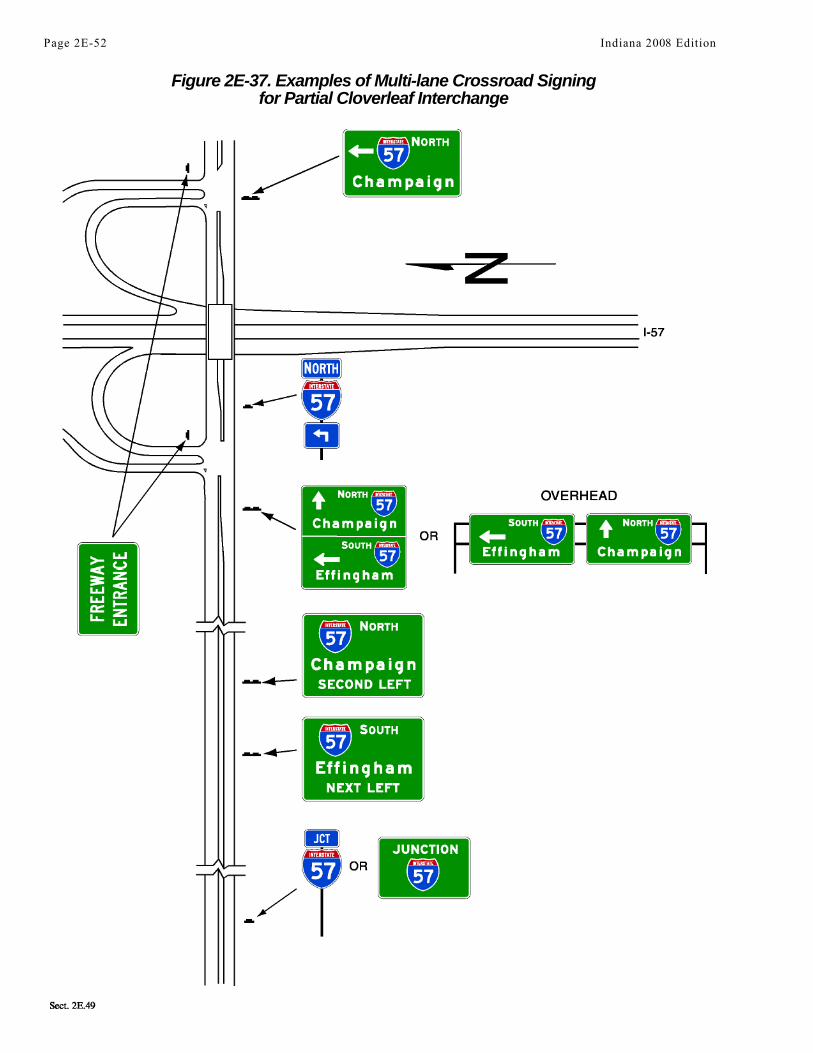
Figure 2E-37. Examples of Multi-lane Crossroad Signingfor Partial Cloverleaf Interchange
Page 2E-52 Indiana 2008 Edition
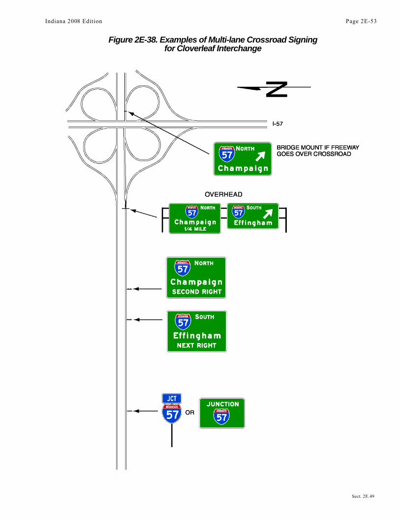
Figure 2E-38. Examples of Multi-lane Crossroad Signingfor Cloverleaf Interchange
Indiana 2008 Edition Page 2E-53
Sect. 2E.49
Section 2E.50 Wrong-Way Traffic Control at Interchange RampsStandard:
At interchange exit ramp terminals where the ramp intersects a crossroad in such a manner thatwrong-way entry could inadvertently be made, the following signs shall be used (see Figure 2E-39):
A. At least one ONE WAY sign for each direction of travel on the crossroad shall be placed where theexit ramp intersects the crossroad.
B. At least one DO NOT ENTER sign shall be conspicuously placed near the end of the exit ramp inpositions appropriate for full view of a road user starting to enter wrongly.
C. At least one WRONG WAY sign shall be placed on the exit ramp facing a road user traveling in thewrong direction.
Guidance:In addition, the following pavement markings should be used (see Figure 2E-39):A. On two-lane paved crossroads at interchanges, double solid yellow lines should be used as a centerline
for an adequate distance on both sides approaching the ramp intersections.B. Where crossroad channelization or ramp geometrics do not make wrong-way movements difficult, a lane-
use arrow should be placed in each lane of an exit ramp near the crossroad terminal where it will be clearlyvisible to a potential wrong-way road user.
Option:The following traffic control devices may be used to supplement the above signs and pavement markings:A. Additional ONE WAY signs may be placed, especially on two-lane rural crossroads, appropriately in
advance of the ramp intersection to supplement the required ONE WAY sign(s).B. Additional WRONG WAY signs may be used.C. Slender, elongated wrong-way arrow pavement markings (see Figure 3B-21) intended primarily to warn
wrong-way road users that they are traveling in the wrong direction may be placed upstream from theramp terminus (see Figure 2E-39) to indicate the correct direction of traffic flow. Wrong-way arrowpavement markings may also be placed on the exit ramp at appropriate locations near the crossroadjunction to indicate wrong-way movement. The wrong-way arrow markings may consist of pavementmarkings or bidirectional red-and-white raised pavement markers or other units that show red to wrong-way road users and white to other road users (see Figure 3B-21).
D. Lane-use arrow pavement markings may be placed on the exit ramp and crossroad near their intersection toindicate the permissive direction of flow.
E. Guide signs may be used on entrance ramps near the crossroad to inform road users of the freeway orexpressway entrance, as appropriate (see Figure 2E-37).
Guidance:On interchange entrance ramps where the ramp merges with the through roadway and the design of the
interchange does not clearly make evident the direction of traffic on the separate roadways or ramps, a ONEWAY sign visible to traffic on the entrance ramp and through roadway should be placed on each side of thethrough roadway near the entrance ramp merging point as illustrated in Figure 2E-40.Option:
At locations where engineering judgment determines that a special need exists, other standard warning orprohibitive methods and devices may be used as a deterrent to the wrong-way movement.Support:
Section 2B.35 contains further information on signing to avoid wrong-way movements at at-gradeintersections on expressways.
Section 2E.51 General Service SignsSupport:
General Service signs (see Figure 2D-11) are generally not appropriate at major interchanges (see Section2E.29 for definition) and in urban areas.Option:
If interchanges are not numbered, an action message such as NEXT EXIT or SECOND RIGHT may be used(see Figure 2E-41).Standard:
General Service signs shall have white letters, symbols, and borders on a blue background. Letter andnumeral sizes shall conform to the minimum requirements of Tables 2E-1 through 2E-4. All approved
Page 2E-54 Indiana 2008 Edition
Sect. 2E.50 to 2E.51

Figure 2E-39. Examples of Regulatory Signing and Pavement Markingsat Exit Ramp Termination to Deter Wrong-Way Entry
symbols shall be permitted as alternatives to word messages, but symbols and word service messages shallnot be intermixed. If the services are not visible from the ramp of a single-exit interchange, the servicesigning shall be repeated in smaller size at the intersection of the exit ramp and the crossroad. Such servicesigns shall use arrows to indicate the direction to the services.Guidance:
Distance to services should be shown on General Service signs where distances are more than 2 km or 1mile.
General Service signing should only be provided at locations where the road user can return to the freeway orexpressway and continue in the same direction of travel.
Only services that fulfill the needs of the road user should be shown on General Service signs. If State or localagencies elect to provide General Service signing, there should be a statewide policy for such signing and criteriafor the availability of the various types of services. The criteria should consider the following:
A. Gas, Diesel, LP Gas, EV Charging, and/or other alternative fuels if all of the following are available:1. Vehicle services such as gas, oil, and water;2. Modern sanitary facilities and drinking water;3. Continuous operations at least 16 hours per day, 7 days per week; and4. Public telephone.
B. Food if all of the following are available:1. Licensing or approval, where required;2. Continuous operation to serve at least two meals per day, at least 6 days per week;3. Public telephone; and4. Modern sanitary facilities.
C. Lodging if all of the following are available:1. Licensing or approval, where required;2. Adequate sleeping accommodations;3. Public telephone; and4. Modern sanitary facilities.
Indiana 2008 Edition Page 2E-55
Sect. 2E.51
Legend
Direction of TravelWrong-Way ArrowsLane Use ArrowsOptional

Figure 2E-40. Examples of Regulatory Signing and Pavement Markingsat Entrance Ramp Terminal Where Design Does Not Clearly
Indicate the Direction of Flow
_____________________________________________________________________________________D. Public Telephone if continuous operation, 7 days per week is available.E. Hospital if continuous emergency care capability, with a physician on duty 24 hours per day, 7 days per
week is available. A physician on duty would include the following criteria and should be signed inaccordance with the priority as follows:1. Physician on duty within the emergency department;2. Registered nurse on duty within the emergency department, with a physician in the hospital on call;or3. Registered nurse on duty within the emergency department, with a physician on call from office or home.
F. 24-Hour Pharmacy if a pharmacy is open, with a State-licensed pharmacist present and on duty, 24 hours perday, 7 days per week and is located within 4.8 km (3 mi) of an interchange on the Federal-aid system.
G. Camping if all of the following are available:1. Licensing or approval, where required;2. Adequate parking accommodations; and3. Modern sanitary facilities and drinking water.
Standard:For any service that is operated on a seasonal basis only, the General Service signs shall be removed
or covered during periods when the service is not available.The General Service signs shall be mounted in an effective location, between the Advance Guide sign and theExit Direction sign, in advance of the exit leading to the available services.Guidance:
The General Service sign should contain the interchange number, if any, as illustrated in Figure 2E-42.Option:
If the distance to the next point where services are available is greater than 16 km (10 miles), a NEXTSERVICES XX km (XX MILES) (D9-17) sign (see Figure 2E-43), may be used as a separate sign panel installedbelow the Exit Direction sign.Standard:
Signs for services shall conform to the format for General Service signs (see Section 2D.45) and asspecified herein. Letter and numeral sizes shall be as shown in Tables 2E-1 through 2E-4. No more than sixgeneral road user services shall be displayed on one sign, which includes any appended sign panels. GeneralService signs shall carry the legends for one or more of the following services: Food, Gas, Lodging, Camping,Phone, Hospital, 24-Hour Pharmacy, or Tourist Information.
The qualified services available shall be shown at specific locations on the sign.To provide flexibility for the future when the service might become available, the sign space normally
reserved for a given service symbol or word shall be left blank when that service is not present.
Page 2E-56 Indiana 2008 Edition
Sect. 2E.51

Figure 2E-41. Examples of General Service Signs(without Exit Numbering)
Figure 2E-42. Examples of General Service Signs(with Exit Numbering)
Figure 2E-43. Example of Next Services Sign
OR
D9-17
Indiana 2008 Edition Page 2E-57
Sect. 2E.51
Guidance:The standard display of word messages should be FOOD and PHONE in that order on the top line, and
GAS and LODGING on the second line. If used, HOSPITAL and CAMPING should be on separate lines (seeFigure 2E-42).Option:
Signing for DIESEL, LP-Gas, or other alternative fuel services may be substituted for any of the generalservices or appended to such signs. The International Symbol of Accessibility for the Handicapped (D9-6) signmay be used for facilities that qualify.Guidance:
When symbols are used for the road user services, they should be displayed as follows:A. Six services:
1. Top row—GAS, FOOD, and LODGING2. Bottom row—PHONE, HOSPITAL, and CAMPING
B. Four services:1. Top row—GAS and FOOD2. Bottom row—LODGING and PHONE
C. Three services:1. Top row—GAS, FOOD, and LODGING
Option:Substitutions of other services for any of the services shown above may be made by placing the substitution in the
lower right (four or six services) or extreme right (three services) portion of the sign panel. An action message or aninterchange number may be used for symbol signs in the same manner as they are used for word message signs. TheDiesel Fuel (D9-11) symbol or the LP-Gas (D9-15) symbol may be substituted for the symbol representing fuel orappended to such assemblies. The Tourist Information (D9-10) symbol or the 24-Hour Pharmacy (D9-20 and D9-20a)symbol may be substituted on any of the above configurations.Standard:
If more than three services become available at rural interchange areas where limited road userservices were anticipated, any appended sign panel shall be removed and replaced with an independentlymounted General Service sign as described in this Section.Option:
A separate Telephone Service (D9-1) sign may be installed if telephone facilities are located adjacent to theroute at places where public telephones would not normally be expected.
The Recreational Vehicle Sanitary Station (D9-12) sign may be used as needed to indicate the availability offacilities designed for dumping wastes from recreational vehicle holding tanks.
In some locations, signs may be used to indicate that services are not available.A TRUCK PARKING (D9-16) sign may be used on a separate sign panel below the other general road user
services to direct truck drivers to designated parking areas.
Section 2E.52 Rest and Scenic Area SignsGuidance:
Signing for rest areas and scenic areas should conform to the provisions set forth in Sections 2D.42 and 2D.43.However, the signs should be suitably enlarged for freeway or expressway application. A roadside area that does notcontain restroom facilities should be signed to indicate the major road user service that is provided. For example, anarea with only parking should be signed with a PARKING AREA (D5-4) sign (see Figure 2E-44). An area with picnictables and parking should be signed with a PICNIC AREA (D5-5c) sign or a Picnic Table Area (D5-5a) symbolsign.
Rest areas that have tourist information and welcome centers should be signed as discussed in Section 2E.53.Scenic area signing should be consistent with that specified for rest areas. Standard messages should read
SCENIC AREA (D6-1), SCENIC VIEW (D6-2), SCENIC OVERLOOK (D6-3), or the equivalent.
Sect. 2E.51 to 2E.52
Page 2E-58 Indiana 2008 Edition

Figure 2E-44. Examples of Rest AreaScenic Overlook, and Welcome Center Signs
D5-1 D5-1a D5-1b
D5-2 D5-2a D5-3
D5-4 D5-7 D5-7a
D5-8 D5-9 D5-9a
D5-10 D5-11
Indiana 2008 Edition Page 2E-59
Sect. 2E.52
Standard:All signs for rest and scenic areas shall have white letters, symbols, and borders on a blue background.
Letter and numeral sizes shall conform to the minimum requirements of Tables 2E-1 through 2E-4. On theapproach to rest areas, a REST AREA advance guide sign shall be placed 2 km or 1 mile and/or 4 km or 2miles in advance of the rest area. At the rest area exit gore, there shall be a sign with a message REST AREAtogether with an arrow indicating the appropriate turn as shown in Figure 2E-44.Option:
If the rest area has facilities for the physically impaired (see Section 2D.45), the International Symbol ofAccessibility for the Handicapped (D9-6) sign may be placed with or beneath the REST AREA advance guidesign.
Between the REST AREA advance guide sign and the gore of the rest area exit, there may be a REST AREA(D5-1b) sign (see Figure 2E-44). The words NEXT RIGHT (E2-2) or an arrow may be included as part of themessage.
To provide the road user with information on the location of succeeding rest areas, a NEXT REST AREA XXkm (XX MILES) (D5-6) sign (see Figure 2E-44) may be installed independently or as a supplemental sign panelmounted below one of the REST AREA advance guide signs.
Section 2E.53 Tourist Information and Welcome Center SignsSupport:
Tourist information and welcome centers have been constructed within rest areas on freeways andexpressways and are operated by either a State or a private organization. Others have been located within closeproximity to these facilities and operated by civic clubs, chambers of commerce, or private enterprise.Guidance:
An excessive number of supplemental panels should not be installed with Tourist Information or WelcomeCenter signs so as not to overload the road user.Standard:
Tourist Information or Welcome Center signs (see Figure 2E-44) shall have a white legend and border ona blue background. Continuously staffed or unstaffed operation at least 8 hours per day, 7 days per week,shall be required.
If operated only on a seasonal basis, the Tourist Information or Welcome Center signs shall beremoved or covered during the off seasons.Guidance:
For freeway or expressway rest area locations that also serve as tourist information or welcome centers, thefollowing signing criteria should be used:
A. The locations for tourist information and welcome center Advance Guide, Exit Direction, and Exit Goresigns should meet the General Service signing requirements described in Section 2E.51.
B. If the signing for the tourist information or welcome center is to be accomplished in conjunction with theinitial signing for the rest areas, the message on the Advance Guide sign should be REST AREA, TOURISTINFO CENTER, XX km (XX MILES) or REST AREA, WELCOME CENTER XX km (XX MILES). Onthe Exit Direction sign the message should be REST AREA, TOURIST INFO CENTER with an upwardsloping arrow (or NEXT RIGHT), or REST AREA, WELCOME CENTER with an upward sloping arrow(or NEXT RIGHT).
C. If the initial rest area Advance Guide and Exit Direction signing is in place, these signs should include,on supplemental sign panels, the legend TOURIST INFO CENTER or STATE NAME (optional),WELCOME CENTER.
D. The Gore sign should contain only the legend REST AREA with the arrow and should not besupplemented with any legend pertaining to the tourist information center or welcome center.
Option:An alternative to the supplemental TOURIST INFO CENTER legend is the Information Symbol (D9-10)
sign, which may be appended beneath the REST AREA advance guide sign. The name of the State or localjurisdiction may appear on tourist information/welcome center signs if the jurisdiction controls the operation ofthe tourist information or welcome center and the center meets the operating criteria set forth herein and isconsistent with State policies. The State name may be used on the Advance Guide and the Exit Direction signs.
Page 2E-60 Indiana 2008 Edition
Sect. 2E.52 to 2E.53
Guidance:For tourist information centers located off the freeway or expressway facility, additional signing criteria
should be as follows:A. Each State should adopt a policy establishing the maximum distance that a tourist information center can
be located from the interchange in order to be included on official signs.B. The location of signing should be in accordance with requirements pertaining to General Service signing
(see Section 2E.51).C. Signing along the crossroad should be installed to guide the road user from the interchange to the tourist
information center and back to the interchange.Option:
As an alternative, the Information Symbol (D9-10) sign may be appended to the guide signs for the exitproviding access to the tourist information center. As a second alternative, the Information Symbol sign may becombined with General Service signing.
Section 2E.54 Reference Location Signs and Enhanced Reference Location Signs (D10-4, D10-5)Support:
Reference Location (D10-1 through D10-3) signs and Intermediate Reference Location (D10-1a throughD10-3a) signs and their applications are described in Section 2D.46.
There are two types of enhanced reference location signs:A. Enhanced Reference Location signs (D10-4), andB. Intermediate Enhanced Reference Location signs (D10-5).
Standard:Except as provided in the option below, Reference Location (D10-1 through D10-3) signs (see Section
2D.46) shall be placed on all expressway facilities that are located on a route where there is referencelocation sign continuity and on all freeway facilities to assist road users in estimating their progress, toprovide a means for identifying the location of emergency incidents and traffic crashes, and to aid inhighway maintenance and servicing.Option:
Enhanced Reference Location (D 10-4) signs (see Figure 2E-45), which enhance the reference location signsystem by identifying the route, may be placed on freeways or expressways (instead of Reference Location signs) oron conventional roads.
To augment an enhanced reference location sign system, Intermediate Enhanced Reference Location (D10-5)signs (see Figure 2E-45), which show the tenth of a kilometer (mile) with a decimal point, may be installed alongany section of a highway route or ramp at one tenth of a kilometer (mile) intervals, or at some other regular spacing.Standard:
If enhanced reference location signs are used, they shall be vertical panels having blue or greenbackgrounds with white numerals, letters, and borders, except for the route shield, which shall be thestandard color and shape. The top line shall consist of the cardinal direction for the roadway. The second lineshall consist of the applicable route shield for the roadway. The third line shall identify the kilometer (mile)reference for the location and the bottom line of the Intermediate Enhanced Reference Location sign shallgive the tenth of a kilometer (mile) reference for the location. The bottom line of the Intermediate EnhancedReference Location sign shall contain a decimal point. The height of the legend on enhanced referencelocation signs shall be a minimum of 150 mm (6 in). The height of the route shield on enhanced referencelocation signs shall be a minimum of 300 mm (12 in).
The background color shall be the same for all enhanced reference location signs within a jurisdiction.The design details for enhanced reference location signs shall be as shown in the "Standard Highway
Signs" book (see Section 1A.11).Enhanced reference location signs shall have a minimum mounting height of 1.2 m (4 ft) to the bottom of
the sign in accordance with the mounting height requirements of delineators (see Section 3D.04), and shallnot be governed by the mounting height requirements prescribed in Section 2A.18.
The distance numbering shall be continuous for each route within any State, except where overlapsoccur (see Section 2E.28). Where routes overlap, enhanced reference location sign continuity shall beestablished for only one of the routes. If one of the overlapping routes is an Interstate route, that routeshall be selected for continuity of distance numbering.
Indiana 2008 Edition Page 2E-61
Sect. 2E.53 to 2E.54

Figure 2E-45. Enhanced Reference Location Signs
The distance measurement shall be made on the northbound and eastbound roadways. The enhancedreference location signs for southbound or westbound roadways shall be set at locations directly opposite theenhanced reference location signs for the northbound or eastbound roadways.Guidance:
The route selected for continuity of distance numbering should also have continuity in interchange exitnumbering (see Section 2E.28). On a route without enhanced reference location sign continuity, the first enhancedreference location sign beyond the overlap should indicate the total distance traveled on the route so that roadusers will have a means of correlating their travel distance between enhanced reference location signs with thatshown on their odometer.Standard:
Except as provided in the option below, enhanced reference location signs shall be installed on theright side of the roadway.Option:
Where conditions limit or restrict the use of enhanced reference location signs on the right side of the roadway,they may be installed in the median. In urban areas, Intermediate Enhanced Reference Location signs may beinstalled on the right side of the roadway, in the median, or on ramps to replace or to supplement the referencelocation signs. Enhanced Reference Location signs may be installed back-to-back in median locations.
Section 2E.55 Miscellaneous Guide SignsSupport:
Miscellaneous Guide signs are used to point out geographical features, such as rivers and summits, and otherjurisdictional boundaries (see Section 2D.48).Option:
Miscellaneous Guide signs may be used if they do not interfere with signing for interchanges or other criticalpoints.Guidance:
Miscellaneous Guide signs should not be installed unless there are specific reasons for orienting the roadusers or identifying control points for activities that are clearly in the public interest. If Miscellaneous Guidesigns are to be of value to the road user, they should be consistent with other freeway or expressway guide signsin design and legibility. On all such signs, the design should be simple and dignified, devoid of any tendencytoward flamboyant advertising, and in general conformance with other freeway and expressway signing.
Page 2E-62 Indiana 2008 Edition
Sect. 2E.54 to 2E.55

Section 2E.56 Radio Information SigningOption:
Radio-Weather Information (D12-1) signs may be used in areas where difficult driving conditions commonlyresult from weather systems. Radio-Traffic Information signs may be used in conjunction with traffic managementsystems.Standard:
Radio-Weather and Radio-Traffic Information signs shall have a white legend and border on a bluebackground. Only the numerical indication of the radio frequency shall be used to identify a stationbroadcasting travel-related weather or traffic information. No more than three frequencies shall be shownon each sign. Only radio stations whose signal will be of value to the road user and who agree to broadcasteither of the two items below shall be identified on Radio-Weather and Radio-Traffic Information signs:
A. Periodic weather warnings at no more than 15-minute intervals during periods of adverse weather;or
B. Driving condition information (affecting the roadway being traveled) at a rate of at least onceevery 15 minutes, or when required, during periods of adverse traffic conditions, and whensupplied by an official agency having jurisdiction.
If a station to be considered operates only on a seasonal basis, its signs shall be removed or coveredduring the off season.Guidance:
The radio station should have a signal strength to adequately broadcast 110 km (70 mi) along the route. Signsshould be spaced as needed for each direction of travel at distances determined by an engineering study. Thestations to be included on the signs should be selected in cooperation with the association(s) representing majorbroadcasting stations in the area to provide: (1) maximum coverage to all road users on both AM and FMfrequencies; and (2) consideration of 24 hours per day, 7 days per week broadcast capability.Option:
In roadway rest area locations, a smaller sign using a greater number of radio frequencies, but of the samegeneral design, may be used.Standard:
Radio-Weather and Radio-Traffic Information signs installed in rest areas shall be positioned such thatthey are not visible from the main roadway.Option:
A Channel 9 Monitored (D12-3) sign or cellular phone sign may be installed as needed.Standard:
Only official public agencies or their designee shall be shown as the monitoring agency on the Channel 9Monitored sign.Support:
Section 2D.45 contains information about the use and application of TRAVEL INFO CALL 511 (D12-5)signs.
Section 2E.57 Carpool and Ridesharing SigningOption:
In areas having carpool matching services, Carpool Information (D12-2) signs (see Figure 2D-12) may beprovided adjacent to highways with preferential lanes or along any other highway.
Carpool Information signs may include Internet addresses or telephone numbers of more than four characterswithin the legend.Guidance:
Because this is an information sign related to road user services, the Carpool Information sign should have awhite legend and border on a blue background.Standard:
If a local transit logo or carpool symbol is incorporated into the Carpool Information sign, themaximum vertical dimension of the logo or symbol shall not exceed 450 mm (18 in).
Indiana 2008 Edition Page 2E-63
Sect. 2E.56 to 2E.57
Section 2E.58 Weigh Station SigningStandard:
Weigh Station signing on freeways and expressways shall be the same as that specified in Section2D.44, except for lettering size and the advance posting distance for the Exit Direction sign, which shall belocated a minimum of 450 m (1,500 ft) in advance of the gore.Support:Weigh Station sign layouts for freeway and expressway applications are shown in the “Standard Highway
Signs” book (see Section 1A.11).
Section 2E.59 Preferential Only Lane SignsSupport:
Additional guidance and standards related to the designation, operational considerations, signing, pavementmarkings, and other considerations for preferential only lanes is provided in Sections 2B.26, 2B.27, 2B.28, 2C.52,3B.22, and 3B.23.Standard:
Ground-mounted advance guide signs shall be provided at least 800 m (0.5 mi) prior to the beginningor initial entry point to all types of preferential only lanes (including barrier-separated, buffer-separated, andconcurrent flow). Ground-mounted guide signs shall be provided at the beginning or initial entry point andat intermediate access points to all types of preferential only lanes.
A combination of guide and regulatory signs shall be used in advance of all preferential only lanes. Theadvance guide signs for preferential only lanes shall be consistent with the requirements of Section 2E.30.
Reversible flow or express lanes that do not have any specific vehicle occupancy or designationrestrictions shall be consistent with the requirements of Chapters 2B and 3B.
Overhead preferential only lane guide signs shall be used only as a supplement to ground-mountedpreferential only lane guide signs unless an engineering study identifies that ground-mounted guide signsare not appropriate for a particular situation or location.
Either the HOV abbreviation or the diamond symbol shall appear in the legend of each preferentialonly lane sign at the designated entry and exit points for all types of HOV lanes (including barrier- andbuffer-separated, concurrent flow, and direct access ramps) in order to alert motorists that there is aminimum allowable vehicle occupancy requirement for vehicles to use the HOV lanes and to inform them ofthe times during which these vehicle occupancy requirements are in effect.Guidance:
Because consistency in signing and pavement markings for preferential only lanes within a State or metropolitanarea plays a critical role in building public awareness, understanding, and acceptance, and makes enforcement moreeffective, an engineering study should be conducted to determine the appropriate combinations of overhead signs,ground-mounted signs, and pavement markings for a specific preferential only lane application.
Existing sign and bridge structures should be used to the extent practical for the installation of preferentialonly lane signs. Where possible, advance guide and guide signs that are provided for preferential only lanesshould share sign structures spanning the preferential only lanes and the adjoining freeway facility.
The preferential only lane signing should be designed to avoid overloading the road user. Based on theimportance of the sign, the following priority should be given: regulatory, advance regulatory, guide, then nextexit supplemental signs.Option:
Overhead advance guide signs and overhead guide signs may be used in advance of, at the beginning orinitial entry point, and at designated intermediate access points to any type of preferential only lane. Advanceguide signs may be installed and located approximately 1.6 km (1 mi) and 3.2 km (2 mi) in advance of thebeginning or initial entry point to any type of preferential only lane.Guidance:
Where conditions restrict the ability to provide more than one advance guide sign in advance of any type ofpreferential only lane, the advance guide sign that is installed should be placed at least 800 m (0.5 mi) in advance ofthe beginning or entry point to the preferential only lane.
Advance destination guide signs, identifying downstream exit locations, should be installed in advance ofdesignated entry points and along the length of access restricted preferential only lanes (such as barrier- andbuffer-separated). In addition to the routes that typically appear on advance destination guide signs, these signs
Page 2E-64 Indiana 2008 Edition
Sect. 2E.58 to 2E.59
should also include destinations. These signs should be located based on the priority of the message, the availablespace, the existing signs on adjoining general purpose traffic lanes, roadway and traffic characteristics, the proximityto existing overhead signs, the ability to install overhead signs, and other unique local factors.Option:
Advance guide signs may be provided for preferential only lanes with unrestricted access, such as concurrentflow preferential only lanes.Guidance:
The use of guide signs for preferential only lanes at freeway interchanges should conform to the regulatoryand guide sign requirements established in this Manual.Option:
Changeable message signs may be used to supplement static signs where travel conditions change or wheremultiple types of operational strategies (such as variable occupancy requirements, vehicle types, or pricingpolicies) are used and varied throughout the day or week to manage the use of, control of, or access to preferentialonly lanes.Standard:
When changeable message signs (see Section 2A.07) are used as regulatory or guide signs forpreferential only lanes, they shall be the required sign size and shall display the required letter height andlegend format that corresponds to the type of roadway facility and design speed.
Ground-mounted and overhead advance guide signs, guide signs, and exit signs applicable to HOVlanes and direct access ramps to HOV lanes shall contain the HOV diamond symbol in the upper leftcorner of the sign as shown in Figures 2E-46 through 2E-52. The diamond symbol shall not be used withlanes designated for bus or taxi traffic.Option:
Agencies may select from either the HOV abbreviation or the diamond symbol to reference the HOV lanedesignation.Guidance:
Where lateral clearance is limited, such as when a ground-mounted Preferential Only Lane sign is installedon a median barrier, the edges of the sign should not project beyond the outer edges of the barrier.Option:
Where lateral clearance is limited, Preferential Only Lane (R3-10, R3-11, and R3-12 series) signs that are 1800mm (72 in) or less in width may be skewed up to 45 degrees in order to fit within the barrier width or may bemounted at a height of 4.3 m (14 ft) or more above the roadway.Guidance:
Where lateral clearance is limited, Preferential Only Lane signs that are wider than 1800 mm (72 in) should bemounted at a height of at least 4.3 m (14 ft) above the roadway.Standard:
For barrier-separated preferential only lanes, overhead advance guide and overhead guide signs shallbe provided in advance of and at the beginning or initial entry point to the preferential only lanes (seeFigure 2E-46 for HOV lanes). Overhead guide signs shall also be used at all intermediate entry points tobarrier-separated preferential only lanes (see Figure 2E-47 for HOV lanes).
For barrier-separated preferential only lanes, ground-mounted advance exit and ground-mountedexit signs shall be installed prior to and at the intermediate exit points of the preferential only lanes (seeFigure 2E-47 for HOV lanes). Ground-mounted guide signs shall be mounted in the median or onmedian barriers that separate two directions of traffic.Option:
For barrier-separated preferential only lanes, an advance destination guide sign may be used in the vicinity ofdesignated intermediate entry and exit points.Guidance:
For barrier-separated preferential only lanes where conditions restrict the ability to provide more than oneadvance guide sign prior to the entrance to the preferential only lane, the sign should be placed approximately800 m (0.5 mi) in advance of the exit. In these situations, the installation of the corresponding regulatory andnext exit supplemental signs should be located based on the priority of the message and the available space.
Indiana 2008 Edition Page 2E-65
Sect. 2E.59

Figure 2E-46. Example of Signing for the Entrance to Barrier-Separated HOV Lanes
Page 2E-66 Indiana 2008 Edition
Sect. 2E.59

Figure 2E-47. Example of Signing for the Intermediate Entry to and Exitfrom Barrier- or Buffer-Separated HOV Lanes
Indian 2008 Edition Page 2E-67
Sect. 2E.59
Standard:For buffer-separated preferential only lanes (painted buffer of 0.6 m (2 ft) or more) where access is
restricted to designated entry points, ground-mounted guide signs shall be mounted in the median or onmedian barriers separating two directions of traffic. Ground-mounted advance exit and ground-mountedexit signs shall be installed prior to and at the intermediate exit points of buffer-separated preferential onlylanes (see Figure 2E-47 for HOV lanes).Option:
For buffer-separated preferential only lanes, an advance destination guide sign may be used in the vicinity ofdesignated intermediate entry and exit points.Guidance:
For buffer-separated HOV lanes, guide and regulatory signs should be provided to alert HOV lane users andnon-users of the minimum allowable vehicle occupancy requirement and the locations of the designated entry andexit points.Standard:
For concurrent flow preferential only lanes, including those where a preferential only lane is added tothe roadway (see Figure 2E-48 for HOV lanes) and those where a general purpose lane transitions into apreferential only lane on the roadway (see Figure 2E-49 for HOV lanes), an overhead regulatory (R3-14 orR3-14a) sign shall be used.
For concurrent flow HOV lanes on the left side of the roadway with unrestricted access, advance guideand guide signs shall only be used on direct access ramps, such as HOV lane only ramps or ramps to park &ride lots (see Figures 2E-50 and 2E-51 for HOV lanes).
For direct access ramps to HOV lanes, advance guide signs shall be provided along the adjoiningsurface streets to direct traffic into a transit facility (such as a park & ride lot or a transit station orterminal) that ultimately leads to HOV lanes (see Figure 2E-50 for HOV lanes).
Because direct access ramps for preferential only lanes at interchanges connecting two freeways aretypically left side exits and typically have design speeds similar to the preferential only lane, overheadadvance guide signs and overhead guide signs shall be provided in advance of and at the entry point toeach preferential only lane ramp (see Figure 2E-52 for HOV lanes).Support:
Figures 2E-50 through 2E-52 provide examples of recommended uses and layouts of signs for HOV lanes fordirect access ramps, park & ride lots, access from surface streets, and exclusive preferential only lane ramps atinterchanges that directly connect two freeway facilities. Direct access ramps to preferential only lanes sometimesform a three or four-legged intersection that is controlled by either static signs or traffic control signals.
The use of advance guide and guide signs for direct access ramps for preferential only lanes at interchangesconnecting two freeways is similar to a connecting ramp between two freeway facilities..
Page 2E-68 Indian 2008 Edition
Sect. 2E.59
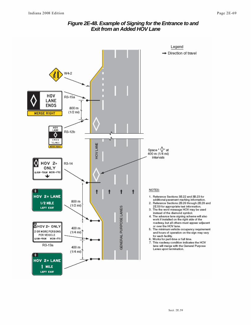
Figure 2E-48. Example of Signing for the Entrance to andExit from an Added HOV Lane
Indiana 2008 Edition Page 2E-69
Sect. 2E.59
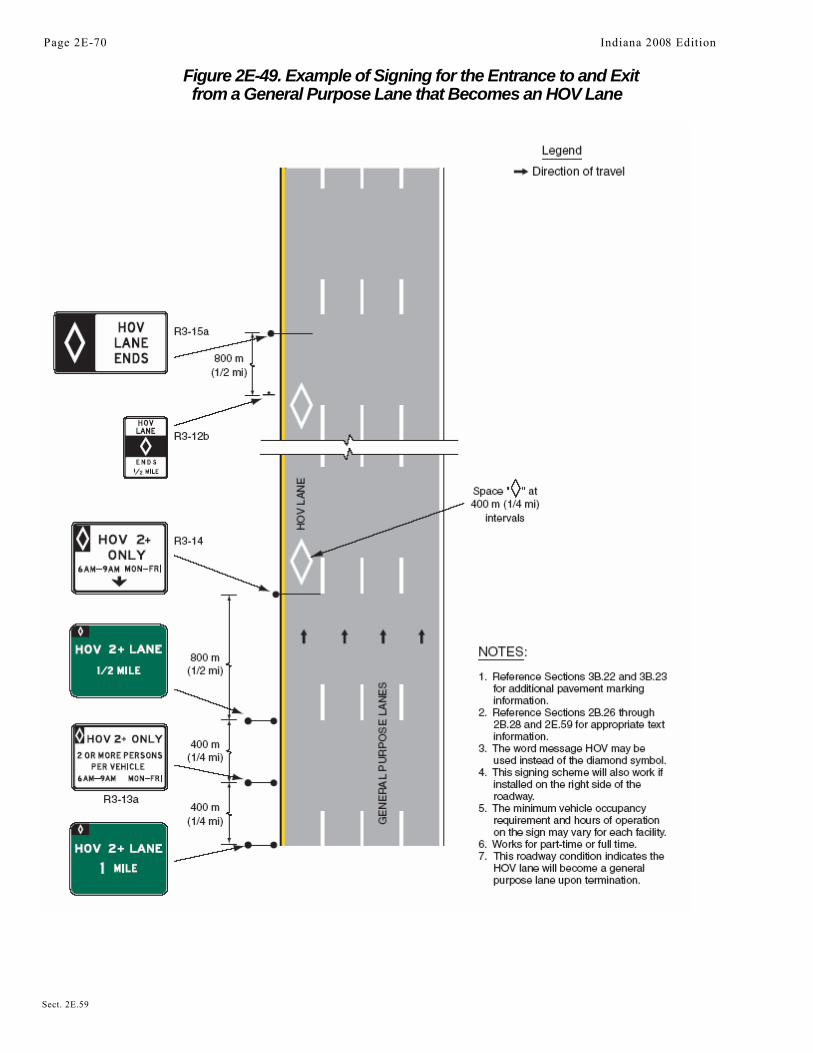
Figure 2E-49. Example of Signing for the Entrance to and Exitfrom a General Purpose Lane that Becomes an HOV Lane
Page 2E-70 Indiana 2008 Edition
Sect. 2E.59

Figure 2E-50. Example of Signing for a Direct Access Rampto an HOV Lane from a Park & Ride Facility
NOTES:
1. Reference Section 3B.22 and 3B.23 for additional pavement marking information.2. Reference Sections 2B.26 through 2B.28 and 2E.59 for appropriate text information.3. Additional advisory and warning signs are required.4. Direction of HOV traffic is inbound.5. Sign locations are approximate.6. The word message HOV may be used instead of the diamond symbol.7. The minimum vehicle occupancy requirement on the sign may vary for each facility.8. Overhead HOV signs should supplement ground-mounted HOV signs.9. Additional signs may be required to direct drivers from the surrounding streets into the park & ride lot and HOV lane.
10. Additional signs are required on the adjoining surface streets to inform non- HOVs that they should not enter the HOV facility.
*For access restricted facilities. Destinations may be augmented to accompany routes on Interchange Sequence signs (see Figure 2E-24).
Sect. 2E.59
Legend
Direction of travel
R3-13a
Indiana 2008 Edition Page 2E-71

Figure 2E-51. Example of Signing for a Direct AccessRamp to an HOV Lane from a Local Street
1. Reference Sections 3B.22 and 3B.23 foradditional pavement marking information.
2. Reference Sections 2B.26 through 2B.28 and2E.59 for appropriate text information.
3. Additional advisory and warning signs arerequired.
4. Sign locations are approximate.5. HOV facility could be barrier-separated,
buffer-separated, or concurrent flow.
For access restricted facilities. Destinations maybe augmented to accompany routes on InterchangeSequence signs (see Figure 2E-24).
Page 2E-72 Indiana 2008 Edition
Sect. 2E.59
NOTES:
Legend
Direction of travel
Local streetconnection

Figure 2E-52. Example of Signing for a Direct Access Rampbetween HOV Lanes on Separate Freeways
NOTES:
1. Reference Sections3B.22 and 3B.23 for additional pavementmarkinginformation.
2. Reference Sections 2B.26 through 2B.28and 2E.59 for appropriate text information.
3. Additional advisory and warningsigns are required.
4. Sign locations are approximate.5. If vehicle occupancy levels vary between
HOV facilities, then the occupancy levelcan be added to guide signs.
6. HOV facility could be barrier-separated, buffer-separated, orconcurrent flow.
Destinations may be augmented to accompany routeson guide signs similar to Figure 2E-3.
For access restricted facilities. Destinations may beaugmented to accompany routes on Interchange
Sequence signs (see Figure 2E-24).
Indiana 2008 Edition Page 2E-73
Sect. 2E.59
