chapter – 2 - information and library network...
TRANSCRIPT

42
CHAPTER – 2
LITERATURE SURVEY
2.1 Compact pulsed power
Compact pulsed power technologies are characterized by concentration of energy both in time
and size to generate pulses of high intensity. Nowadays the pulsed power field is driven by size,
weight, and volume constraints and certain applications require technology that can be deployed
in smaller volume under stressful environments. In both the military and commercial
applications, there is an overwhelming need to provide more and more capability in ever smaller
and lighter packages [20]. The need for higher energy density, power density and efficiency is
driving further progress in the field. The pulse conditioning system is an important part of pulsed
power system, its general functions are the storage, switching, and scaling (Figure 2.01) [21].
Pulse Conditioning System
Figure 2.01 Basic pulsed power supply architecture
In order to minimize the weight and volume of the system, two types of system architectures are
routinely considered. The first architecture is one that stores all the energy required for multiple
pulses and then uses an opening and closing switch to transfer the energy to the load (Figure
2.02). This approach is the simplest in operation, but requires a much larger volume for the
energy storage.
Opening & Closing Switch
Figure 2.02 Multiple pulse store architecture
Prime Power
High Voltage Power Supply
Shape Load Store Scale
Prime Power Source
Charging System
Multiple Pulse Store
Load

43
The second architecture is a single pulse storage system with repetitive charge system (Figure
2.03).
Charge switch Closing switch
Figure 2.03 Single pulse storage with recharge The single pulse system will provide the minimum energy storage volume, but requires increased
complexity. The minimum system volume and thus weight will be one in which all the
operations required to store, scale, and shape the load pulse are performed in the same volume as
illustrated in Figure 2.04.
Figure 2.04 Ideal compact pulse power system
The pulsed power has expanded its capabilities in the later half of 20th centaury with the research
and development in improved materials and electrical components with high energy and power
densities. Multidisciplinary university research initiative program was also started in United
States during the starting of 21st century to study the fundamental issues for development of
compact pulsed power systems [3]. The recent advancements in high energy density components
(capacitors, cores etc), and new solid-state devices have enabled pulsed power systems to
undergo reduction in size and weight [22]. Modern electronic products depend on pulsed power
to convert ac or battery power, as the pulsed converter become smaller, and occupy an ever
smaller portion of the product volume. Computers that were once giants have now shrunk to
pocket-size. Our appetite for small, lightweight, yet powerful devices extends well beyond the
domestic purpose to include defence, industry, medicine, and research. The demand is increasing
Prime Power High Voltage Power Supply
Shape Scale Store
Load
Prime Power Source
Charging System
Multiple Pulse Store
Load

44
for pulsed power to serve ever smaller applications with reliable, efficient, lightweight power
sources and the response has been a sustained trend toward compact pulsed power technologies.
The compact pulsed power research is more application specific nature than an organized effort
[23]. A compact pulsed power technologist absorbs advanced ideas and components from other
efforts and knit them together into a unique system that may have little to do with the original
component or its intended purpose. For example, a high power solid-state switch, developed for
the traction industry, might be combined with a high energy density capacitor, developed for a
small computer power supply, and the entire circuit powered by a long-life battery developed for
a new generation of cellular phones. While the general demand for compact sources increases,
the case by case development of a new source is typically achieved by raw innovation. Many
historic examples of compact pulsed power are available in the literature. One such paper
illustrates how a commercial switching system becomes smaller with each new generation [24],
while others cite examples of compact components, such as capacitors [25], transformers [26],
and pulse generators [27].
2.2 Research issues in compact pulsed power technology
The development of compact pulsed power technology requires combined efforts at three levels:
efficient and robust devices at component levels, novel circuits and architecture at the system
level, and effective technique to deliver fast pulses at the application levels. On-going research
and development at international level in capacitor technology and dielectric materials has
resulted in significant expansion in several dimensions of the film capacitor operating envelope.
Research in high-voltage film capacitors has produced a self-healing feature that extends
capacitor life under harsh pulsed power uses. The new dielectrics have produced new high
energy density materials that enable capacitors to store more energy in ever smaller packages

[28-29]. The capacitor technology developments
be reached over the last few years. This progress shows no indication of levelling off in the near
future (Figure 2.05).
Figure 2.05 Progress in capacitor energy density versus time [23]
Advancement of capacitor construction
stored energy density, pulse life, and DC life
capacitors used in pulsed power systems
significant improvement in capacitor construction technology. If an internal breakdown should
occur, the metal film is vaporized at the fault site and thereby disconnects the problem area from
the remaining capacitor [31].
Ceramic dielectric materials such as dense titania ceramic and nanocrystalline titanium oxide
developed and studied to make transmission lines with higher energy storage capabilities for
compact pulsed power applications [
45
The capacitor technology developments have enabled much higher energy densities to
few years. This progress shows no indication of levelling off in the near
Progress in capacitor energy density versus time [23]
Advancement of capacitor construction methods and dielectric quality has resulted in improved
stored energy density, pulse life, and DC life. W J Sergeant [30] has reported a review of
capacitors used in pulsed power systems. The use of very thin metalized
significant improvement in capacitor construction technology. If an internal breakdown should
occur, the metal film is vaporized at the fault site and thereby disconnects the problem area from
such as dense titania ceramic and nanocrystalline titanium oxide
developed and studied to make transmission lines with higher energy storage capabilities for
compact pulsed power applications [32-33]. Very low impedance pulse forming
have enabled much higher energy densities to
few years. This progress shows no indication of levelling off in the near
Progress in capacitor energy density versus time [23]
and dielectric quality has resulted in improved
has reported a review of
. The use of very thin metalized film electrodes is a
significant improvement in capacitor construction technology. If an internal breakdown should
occur, the metal film is vaporized at the fault site and thereby disconnects the problem area from
such as dense titania ceramic and nanocrystalline titanium oxide are
developed and studied to make transmission lines with higher energy storage capabilities for
]. Very low impedance pulse forming lines can be

46
made with ceramic materials for low impedance load such as z-pinches. From the literature
survey it was found that the research on high voltage insulation material is one area which can
help in designing very compact systems. This area of research also explores development of high
relative permittivity material. But both of this will lead to material science research for the
development of new materials. The other reliable solution will be to use the best of the material
available in this field and continue development of compact systems. Ceramic materials very
high relative permittivity and could be used for making compact pulsed power system but it is
not much explored for designing pulsed power system due to its piezoelectric properties. The
newer techniques for storing energy could be explored for making compact pulsed power system.
Study of pulsed breakdown in liquid dielectric has received considerable attention in recent years
due to great demands from pulsed power field for the development of liquid dielectric
transmission lines. Liquids dielectric has played a major role as dielectric material in energy
storage, pulse forming, and switching in the development of pulsed power technology. The
switching utilizes liquid breakdown at high fields, thus going beyond just the insulating property
of liquids. However, in energy storage and pulse forming breakdown is detrimental to the proper
functioning of a pulsed power system. It is also obvious that the size of a pulsed power system
has always been a concern, and the effort of making existing systems even more compact will
have to deal with the higher electric fields that come with the inherently smaller distances of a
compact system. Though an abundance of experimental data is available for breakdown in
various insulating liquids, such as water, cyclohexane, and the noble gases, the basic physics of
liquid breakdown has remained unclear. The two classic physical models are the crack
propagation, which was recently transferred from solid breakdown, and the older bubble
mechanism [34]. The main motivation for the development of liquid dielectrics for pulsed power

47
applications is their structural compatibility with high power pulsed system. There are a large
variety of liquids that can be used but for practical usage, mineral oil and water is widely used in
pulsed power systems. Mineral oil has high dielectric strength and small dielectric constant so it
is suitable for making low impedance systems. Water is attractive due to its high dielectric
constant, high dielectric strength and efficient energy storage capability.
The longer duration rectangular pulse has also attracted more and more interest in the
development of pulse power technology. In development of compact pulsed power system, a
general research issue is to improve the system architecture. For example, study the geometry-
driven issues in pulse forming line. A paper discussed the edge effect of the water blumlein for
short pulse widths through computational modelling, and optimized the line design based on
three dimensional simulations [35]. Another paper investigated the effects of folds on dielectric
breakdown and the voltage waveform at the load in a folded blumlein [36]. Alternative
topologies and novel engineering techniques should be investigated and the optimization of the
geometry can be done using any electromagnetic software.
An important current trend also in pulsed power technology is the development of compact
repetitive pulsed power systems, which have many important applications in defence and other
industrial areas. The trend in repetitive-pulse-power system design is toward higher energies,
larger average power levels, and faster pulse-repetition rates. There is a great demand of
repetitive pulsed power system, but there are few technical problem needs to be investigated and
resolved. Repetitive pulsed power generation by compact sources is being developed for
industrial applications. Successful introduction of pulsed power technologies in industries
depends to a great extent on the availability of highly efficient and reliable cost-effective
sources. Compact repetitive pulsed power systems can be improved by enhancing the peak and

48
average power output, increasing the pulse repetition frequency and reducing the equipment size
to meet the demands of the increasing applications [37]. Improvements can be made in pulsed
power system components. The electrical insulation and dielectric breakdown should be
considered as the design criteria of an improved compact repetitive system.
Some issues of fundamental importance are needed to be investigated for compact pulsed power
system developments such as new materials for high dielectric strength and high dielectric
constant, exploring alternate engineering topologies for compact systems, improvements in
switches etc. The research issues are still open on studying and utilizing new materials-
dielectrics, insulators, metals, and interface in the design of components of the compact pulsed
power systems. Fundamental studies on compact pulsed power system development with new
materials and novel engineering techniques are needed to be investigated to reduce the size of the
system. The energy density of pulsed power systems is often limited by the storage capabilities
of the dielectric subsystem. Advances in pulsed power switches, capacitors, pulse forming line
are necessary to develop compact, reliable electrical power on directed energy systems as well as
space platforms for military applications. Research is also underway by to gauge the future of
compact pulsed power by investigating the fundamental limits of dielectric materials and pulsed
power components.
2.3 Primary energy storage system
The primary energy storage systems generally used are capacitive, inductive, chemical and
inertial. Electrical energy is typically stored in capacitors as electric field and inductors as
magnetic field. It can also be stored as mechanical energy in rotating wheel and flywheel, and in
the form of chemical energy in batteries and explosives. Table 2.01 shows the salient features
and comparison of these energy storage systems.

49
Primary energy
storage device
Energy density
(MJ/m3)
Energy /Weight
(J/Kg)
Typical transfer
Time (Seconds)
Capacitors 0.01 – 1 300 – 500 microseconds
Explosives 6000 5 x 10⁶ microseconds
Inductors 3 – 40 102 – 103 micro – milliseconds
Flywheel 400 104 - 105 seconds
Battery 2000 106 hundreds of seconds
Table 2.01 Comparison of energy storage systems
High explosives have the highest energy density and the shortest energy release times, but they
are limited to single-shot operation and require auxiliary equipment to convert their chemical
energy into electrical energy. A battery has a high energy storage density but a low power delivery
capability, and requires both long charge and discharge times. Inertial storage has a high storage
density and a moderate power output capability, and capacitors have the highest electrical
discharge capability but they have a relatively low energy storage density. Releasing this stored
energy over a very short interval to generate peak power by a process called energy compression.
Electrical energy stored in a pulsed power system is released in the form of an intense high
voltage and high power pulse or repetitive pulses. There has been rapid development in electrical
pulsed power systems over the past few decades. Two different means of energy storage utilized
in electrical pulsed power systems are capacitive energy storage (CES) and inductive energy
storage (IES). The circuits of the inductive storage systems are duals of the corresponding
capacitive storage systems (Figure 2.06). The CES has capacitor banks and closing switches
while IES has inductive coils and opening switch. In IES the switch must carry the large coil
current during the storage time, interrupt the current, and then withstand the high voltage

generated by the coil current flowing through the load. The opening switch problem is difficul
enough for single-shot operation in many applications
the practical use of inductive storage in pulsed
obvious when the basic capacitive and
Fig
In the capacitive energy discharge circuit (F
resistor R to voltage V. The time constant for the self
where Rc is the leakage resistance
the charging current can be kept fairly low.
discharged into the load ZL by means of the closing switch S
large compared to the charging current and a capacitive discharge circuit can
current amplifier.
Figure 2.0
50
generated by the coil current flowing through the load. The opening switch problem is difficul
shot operation in many applications [38]. There are two major obstacles to
the practical use of inductive storage in pulsed power systems, both of which become
obvious when the basic capacitive and inductive energy discharge circuits ar
Figure 2.06 Comparison of CES and IES
tive energy discharge circuit (Figure 2.07) the capacitor C is ch
voltage V. The time constant for the self- discharge of the capacitor is
is the leakage resistance, may be of the order of tens of minutes. For
the charging current can be kept fairly low. In a practical system the capacitor will typically be
by means of the closing switch Sc. The discharge current is
the charging current and a capacitive discharge circuit can
Figure 2.07 Capacitive energy discharge circuit
generated by the coil current flowing through the load. The opening switch problem is difficult
There are two major obstacles to
, both of which become
inductive energy discharge circuits are compared.
the capacitor C is charged through a
discharge of the capacitor is τc = RcC
, may be of the order of tens of minutes. For such capacitors,
In a practical system the capacitor will typically be
. The discharge current is usually
the charging current and a capacitive discharge circuit can be considered as a

If dWC/ dt is the rate of increase of stored energy in the capacitor and
energy is dissipated in the load, then during charging the capacitor we have
Where R is in series with C and V is the voltage across C.
Suppose the capacitor C is charged by a constant current charger
Then equation 2.01 can be written as
Where T is the charging time of the capacitor and slow charging is best since this gives T
and a low loss in the resistor R while the capacitor is charging.
In the inductive energy storage circuit
the time constant for the L-R circuit is
current source, the switch So and the inductor.
Figure 2.0
For inductive energy storage systems,
have to be charged in relatively short times, a
energy stored in the inductor is transferred to the load by
51
is the rate of increase of stored energy in the capacitor and dWR
energy is dissipated in the load, then during charging the capacitor we have
R is in series with C and V is the voltage across C.
Suppose the capacitor C is charged by a constant current charger (It), such that
.01 can be written as,
charging time of the capacitor and slow charging is best since this gives T
and a low loss in the resistor R while the capacitor is charging.
In the inductive energy storage circuit (Figure 2.08), the inductor L is charged to a current I,
R circuit is τL = L/R, where R is the combined series resistance of the
current source, the switch So and the inductor.
Figure 2.08 Inductive discharge circuit
ductive energy storage systems, τL can be in the order of seconds, which means that inductors
have to be charged in relatively short times, and high power primary sources are needed. The
energy stored in the inductor is transferred to the load by means of an opening switch S
R/dt is the rate at which
(2.01)
, such that, V(t) = It/C ,
(2.02)
charging time of the capacitor and slow charging is best since this gives T >> τc
, the inductor L is charged to a current I, and
= L/R, where R is the combined series resistance of the
seconds, which means that inductors
sources are needed. The
means of an opening switch So, which

52
interrupts the current (I) in the charging circuit and a closing switch Sc, which in turn connects to
the load ZL. Due to the rapid decrease of current, a high voltage of magnitude L(dl/dt) is induced
across the opening switch and load, and inductive discharge circuits can, therefore, be
considered as voltage amplifiers.
If dWL/dt is the rate of stored energy in the inductor L and dWR/dt is the rate at which energy is
dissipated in the load the rate of energy in the magnetic field of the inductor, divided by the
energy dissipated in the series resistance in the same time is
(2.03)
Now di/dt = i/T, where T is the charging time and L/R = τL, the inductor time constant, So for a
high charging efficiency, i.e a large (dWL/dt)/(dWR/dt), one must ensure that τL/T is large, which
means charging rapidly with respect to the inductor time constant. It is evident that the two major
technical complexities encountered in inductive energy storage systems are the charging circuit,
because of the necessary fast charging of the inductor, and the opening switch because of its
in built complexities at the currents and voltage involved [39]. Energy storage for pulsed power
systems commonly implies capacitive storage for which the state of the art is relatively well
developed. The components of capacitor banks, including capacitors and switches, are
commercially available and relatively inexpensive. We will be using capacitive energy storage
system for primary energy storage in our project. It is very essential to study and investigate
different type of capacitors and select best suitable capacitor to make a compact system.
2.31 Capacitors for pulsed power
The recent advancements in energy storage capacitor technologies have enabled reduction in size
of pulsed power systems. R. A Cooper et. al. [40] has reported the progress in the reduction of
inductance to 50 nH in energy storage capacitor. Improvement in polymer film quality and

53
construction techniques has increased the energy densities [30]. Energy storage capacitors have
been developed over a long time and a lot of them got their names from the material used as
dielectric and the electrode type. The capacitors used for compact pulsed power application are
shown in Figure 2.09. Dielectric is an important component in capacitors to store the electrical
energy. Most of the dielectrics used nowadays are ceramics, plastic films, oxide layer on metal
(aluminium, tantalum, niobium), natural materials (mica, glass, paper, air, vacuum). All of them
store their electrical charge statically within an electric field. The important parameters of these
dielectric used in capacitors are mentioned in Table 2.01
Figure 2.09 Capacitors used in compact pulsed power applications
54
Capacitor Type
Dielectric Material Permittivity @ 1 kHz
Max dielectric strength(V/µm)
Min dielectric thickness (µm)
Ceramic Paraelectric 12 – 40 < 100 1
Ceramic Ferroelectric 200 - 14000 < 25 0.5
Film Polypropylene 2.2 650 3.0
Film Polyester 3.3 580 0.7
Film Polyphenylene sulfide 3.0 470 1.2
Film Polyethylene Naphthalate 3.0 500 0.9
Film Polytetrafluroethylene 2.0 250 5.5
Paper Paper 3.5 – 5.5 60 5 – 10
Aluminum Aluminum oxide ( Al2O3) 9.6 710 < 0.01
Tantalum Tantalum pentoxide (Ta2O5) 26 625 < 0.01
Niobium Niobium pentoxide (Nb2O5) 42 455 < 0.01
Mica Mica 5 - 8 118 4 - 50
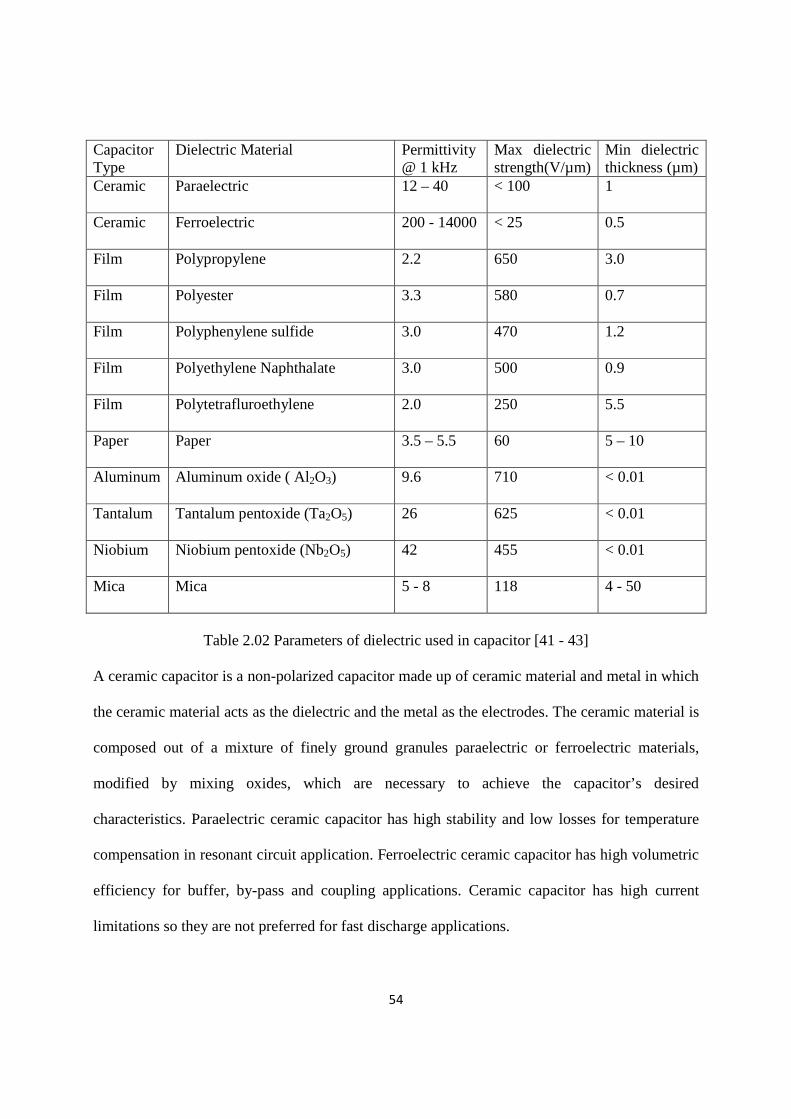
Table 2.02 Parameters of dielectric used in capacitor [41 - 43]
A ceramic capacitor is a non-polarized capacitor made up of ceramic material and metal in which
the ceramic material acts as the dielectric and the metal as the electrodes. The ceramic material is
composed out of a mixture of finely ground granules paraelectric or ferroelectric materials,
modified by mixing oxides, which are necessary to achieve the capacitor’s desired
characteristics. Paraelectric ceramic capacitor has high stability and low losses for temperature
compensation in resonant circuit application. Ferroelectric ceramic capacitor has high volumetric
efficiency for buffer, by-pass and coupling applications. Ceramic capacitor has high current
limitations so they are not preferred for fast discharge applications.

55
Film capacitors are non polarized capacitors with an insulating plastic film as the dielectric. The
dielectric films are drawn in a special process to an extremely thin thickness, provided with
metallic electrodes and wound into a cylindrical shaped winding. The electrodes of film
capacitors may be metalized aluminium or zinc applied to the surface of the plastic film.
Metalized film capacitors possess self-healing properties that is dielectric breakdowns between
the electrodes are not leading to the destruction of the capacitor. The metalized type of
construction makes it possible to produce wound capacitors with larger capacitance values (up to
100 µF and larger) in smaller cases than within the film/foil construction. Film/foil capacitors or
metal foil capacitors are made of two plastic films as the dielectric each covered with a thin
metal foil, mostly aluminium, as the electrodes. The advantage of this construction is the easy
contractibility of the metal foil electrodes and the excellent current pulse strength. A key
advantage of every film capacitor internal construction is direct contact to the electrodes on both
ends of the winding. This contact keeps all current paths to the entire electrode very short. The
setup behaves like a large number of individual capacitors connected in parallel, thus reducing
the internal ohmic losses and the parasitic inductance. The inherent geometry of film capacitor
structure results in very low ohmic losses and a very low parasitic inductance, which makes them
especially suitable for applications with very high surge currents applications, or for applications
at higher frequencies. The plastic films used as dielectric for film capacitors are Polypropylene,
Polyester, Polyphenylene Sulphide, Polyethylene Naphthalate and Polytetrafluoroethylene or
Teflon .
Kraft paper is impregnated with electrical grade castor oil or similar high dielectric constant fluid
with extended foil plates. It is designed for intermittent duty, high current discharge application.
The advantage of these capacitors is enhanced tolerance to voltage reversal and its disadvantages

56
are lower energy densities and large size. Dry and oil filled constructions are available using a
variety of dielectric materials- polypropylene, kraft and polyester with both foil and metalized
electrodes. In recent times the high energy density achieved from metalized, segmented
metalized paper and segmented metalized polypropylene has allowed designers to benefit from
the higher energy density achieved from this construction.
Electrolytic capacitors have a metallic anode which is covered with an oxidized layer used as
dielectric. The second electrode of electrolytic capacitors is a non solid or solid electrolyte.
Electrolytic capacitors are polarized electrical components. Three families of electrolytic
capacitors used are aluminium electrolytic capacitors with aluminium oxide as dielectric,
tantalum electrolytic capacitors with tantalum pentoxide as dielectric, niobium electrolytic
capacitors with niobium pentoxide as dielectric [44]. The anode of electrolytic capacitors is
highly roughened to extend the surface area which increases the capacitance value. The relatively
high permittivity of the oxide layers gives these capacitors the very high capacitance per unit
volume compared with film or ceramic capacitors. The electrical parameters of the capacitors are
established by the material and composition of the electrolyte, especially by the conductivity.
Three types of electrolytes used are non solid electrolyte which has electrical conductivity ( ~
10 mS/cm), Solid manganese oxide electrolyte is of high quality and forms long time stable
capacitors, its electrical conductivity (~ 100 mS/cm), Solid conductive polymer electrolyte for
capacitors with very low ESR values down to values <10 mΩ, its electrical conductivity (~
10,000 mS/cm). The larger capacitance per unit volume of electrolytic capacitors than other
types makes them valuable in relatively high-current and low-frequency electrical circuits.
The supercapacitor is an electrochemical capacitor whose capacitance value is composed of a
static capacitance stored in electric field with in double layer and pseudo capacitance stored
57
electrochemically with redox reactions and charge transfer between electrode and electrolyte
[45]. The capacitance of double layer capacitor is the charge stored statically in electric fields
within the double-layers on the surfaces of the two electrodes. A double layer is a structure that
appears on the solid surface of an electrode when it is placed into a liquid. The thickness of this
structure acting like a dielectric is on the scale of nanometers so it has the energy density
hundreds of times greater compared with conventional electrolytic capacitors. The pseudo
capacitors store charges through adsorption, reversible redox reactions and intercalation of ions
combined with charge transfer between electrolyte and electrode [46]. Pseudo capacitors can
achieve much higher specific capacitance and energy density than double layer capacitors. The
energy density of a pseudo capacitor can be as much as 100 times higher than in a double-layer
capacitor. In parallel to the research of the pseudocapacitance the conductivity of electrolytes for
double-layer capacitors could be reduced. Low ohmic double layer capacitors for high power
applications were developed. Hybrid capacitors were developed it has new electrode materials
such as Lithium ion to increase the pseudocapacitance.
Capacitors used in pulse power circuits are generally high voltage, fast discharge type designed
to have low inductance and low series resistance. Typically they are charged over a relatively
long period of time and then discharged via a closing switch in microseconds or milliseconds.
The figure of merit used in assessing pulsed power capacitors includes energy density, peak
current rating, inductance and reliable lifetime [47]. The rapid charging capacitor bank power
supplies using solid state devices available in market. These power supplies are prone to failure
in intense electromagnetic environment. Power supplies can be made using simple resistive
charging circuit and its resistance is optimized for the fast charging [48].

2.4 High voltage generator for pulse charging
High voltage generation circuits are either based on
generators offer a common way of generating high voltage impulses that are higher than the
available charging supply voltage.
generators are developed using ceramic capacitors
plastic case capacitors for HPM s
driven circuits are designed to
advantage over Marx generator
driving energy requirement, only one single switch for energy transfer and capacity to run on
high repetition rates. The pulse transformer transfers
capacitor to another capacitor under matched load condition
it is mandatory to have a coupling coefficient between windings of the tr
or 0.153 [51 - 52]. The unloaded waveforms of
shown in Figure 2.10.
Figure 2.10 Unloaded waveforms of
E.A Abramayan et. al. [53
duration transformer based accelerator for intense electron beam generation. P Sarkar et. al. [55]
has also reported the design of half Mega volt transformer for EMP gen
58
for pulse charging
High voltage generation circuits are either based on Marx generator or a pulse transformer. Marx
generators offer a common way of generating high voltage impulses that are higher than the
available charging supply voltage. Fast rise time, low energy and high peak power Marx
using ceramic capacitors for applications in UWB
HPM sources [50]. At lower energy levels (< 5 kJ) p
driven circuits are designed to operate as Tesla or double resonance circuit
generator due to its compact size, low input voltage on primary side, low
driving energy requirement, only one single switch for energy transfer and capacity to run on
The pulse transformer transfers the energy efficiently from
capacitor to another capacitor under matched load condition. For the maximum energy transfer,
it is mandatory to have a coupling coefficient between windings of the transformer
The unloaded waveforms of Tesla transformer for coupling coefficients are
Unloaded waveforms of Tesla transformer output
E.A Abramayan et. al. [53 -54] has reported the design and development of
transformer based accelerator for intense electron beam generation. P Sarkar et. al. [55]
has also reported the design of half Mega volt transformer for EMP generation.
arx generator or a pulse transformer. Marx
generators offer a common way of generating high voltage impulses that are higher than the
high peak power Marx
applications in UWB [49] and using
At lower energy levels (< 5 kJ) pulse transformer
esla or double resonance circuit that has added
due to its compact size, low input voltage on primary side, low
driving energy requirement, only one single switch for energy transfer and capacity to run on
the energy efficiently from energy storage
For the maximum energy transfer,
ansformer as 0.6, 0.385
esla transformer for coupling coefficients are
esla transformer output [51]
54] has reported the design and development of micro second
transformer based accelerator for intense electron beam generation. P Sarkar et. al. [55]
eration.

59
2.5 Intermediate energy storage system
The pulse transformers that are used in the microsecond range cannot be used to transform high-
voltage pulses of nanosecond duration because of higher inductances and capacitances of the
windings that lengthen the pulse rise time and distort the pulse waveform. So, an intermediate
energy storage system is needed to deliver peak power to the loads. An intermediate energy
storage system accumulates electrical energy over a comparatively long time, and then releases
the stored energy in the form of a square pulse of comparatively short duration for various pulsed
power applications. They are also known as pulse forming lines (PFL) or pulse forming networks
(PFN). A PFN consists of a series of high voltage energy storage capacitors and inductors. These
components are interconnected (as a "ladder network") that behaves similarly to a length of
transmission line. The component values of the PFN are optimized to synthesize a pulse output
with minimum flattop ripple. A PFL or PFN is charged by means of a high voltage power source,
and then rapidly discharged into a load via a high voltage switch, such as a sparkgap.
2.51 Pulse forming lines
Pulse forming line is simplest of all pulse conditioning techniques, it starts with slow charging
process and gets tens of nanoseconds output pulses with flat top amplitude. It can be made by off
the shelf available coaxial cable or putting two-three concentric cylinders. Coaxial PFL is the
simplest both in terms of structure and operation. It is simple to construct and easy to operate,
however, the drawback is that the output voltage is half of the charging voltage. A brief
comparison of various types of PFL’s is mentioned in Table 2.03. The electrical energy is stored
in the dielectric medium of the intermediate energy storage system for very short duration
(micro-seconds to milliseconds). Solid and liquid dielectrics are used for pulsed energy storage
in the PFL. The compactness of the system depends up on the dielectric constant of the medium.

60
S.No Characteristics Coaxial PFL Blumlein PFL Strip forming line
1 Characteristic Impedance High Very high Low
2 Size Medium Large Compact
3 Electric Field Low Low High
4 Output Voltage Half of charging Equal to charging Half of charging
5 Operating Voltage Medium High Low
Table 2.03 Comparison of various PFLs
2.511 Pulse forming line using solid dielectric
Solid dielectrics materials have higher breakdown strength compared to liquid and gases
dielectrics. A good solid dielectric should have low dielectric loss, high mechanical strength,
should be free from gaseous inclusions, and moisture, and be resistant to thermal and chemical
deterioration. Studies of the electrical breakdown in solid dielectrics are of extreme importance
in pulsed power applications. When breakdown occurs, the solid dielectric get permanently
damaged, while gases fully and liquids partly recover their dielectric strength after the applied
electric field is removed. The conductivity of solid dielectric is not negligible when the electric
field exceeds more than 100 kV/cm, it increases rapidly with electric field. The conductivity in
solid dielectric at higher fields is due to field emission from electrodes, field aided thermionic
emission and field enhanced ionization of impurities. The breakdown strength can be improved
by ultimately reducing or inhibiting these effects. The main factors that influence the solid
breakdown strength are dielectric type and properties, thermodynamic and mechanical states,
structural defects and impurities, electrode material and surface conditions, applied voltage, gap
geometry, other environmental effects, etc [57 - 58].

61
The static and dynamic nature of high voltage testing is used for the testing of solid dielectric
insulation. M M Morcas et. al. [59] and D B Watson et. al. [60] has reported a brief overview of
the application of statistical methods to establish the insulation strength and life time of solid
dielectrics. The short term solid dielectric breakdown studies is also reported by weibull
statistical analysis [61- 63]. Solid dielectric is generally considered to be non-recoverable in the
event of dielectric breakdown but there are single shot pulsed power applications where its use is
warranted. This can result in increased system capacitance with the possibility of operating at
increased energy levels or reduced system volumes. However solid insulation failure under
pulsed power conditions is not fully understood. Solid dielectric materials have been used as
intermediate energy store for pulse compression using high voltage cables [64]. The
investigation on high dielectric strength with high dielectric constant materials is one area which
can help in designing very compact and sophisticated systems. Ceramic materials has very high
relative permittivity and could be explored for making compact pulsed power system, but it is
not much used in pulsed power system due to its piezoelectric properties [4]. Ceramic mixed
with epoxies are tried and considerable increase in dielectric constant was seen [4]. Ceramic tiles
have been made and it has been possible to charge them up to 60 kV [33].
2.512 Pulse forming line using liquid dielectric
Liquid dielectric is used in high voltage systems to serve the dual purpose of insulation and heat
conduction. The advantage of liquid dielectric is that a breakdown path is self healing and the
temporary failures due to overvoltage are reinsulated quickly by fluid flow to the attached area.
Efforts to understand breakdown mechanisms in a variety of liquid dielectric are continued for
longer time. There is no single theory that has been unanimously accepted for breakdown in
liquid dielectric unlike in gases and solid because of complex and not regular molecular structure

62
of liquid. The effect of short- and long-term electric strengths of dielectrics as functions of
various influencing factors is studied and reported [65]. Methods of improving working field
strengths and calculating the static, volt-second and statistical characteristics of the electric
strength of insulation and the insulation service lifetime and reliability are also investigated.
Factors influencing the electric strength includes dielectric material properties, states (pressure,
density, viscosity, temperature, molecular, mechanical stress condition, etc.), electrode material,
electrode surface, contaminations, polarity (for dc and impulse), type (for ac, frequency is also a
factor), duration (for pulses) of the voltage, insulation gap geometry and other environmental
conditions [58]. The increase in hydrostatic pressure will increase the electric strength of liquids
for large electrode areas and for long voltage pulses (>1 µs) [66]. For very pure liquids under
short-term voltage exposure, the main effect of temperature on electric strength is due to the
temperature-dependent density. The electric strength slowly decreases with the increasing
temperature and the decrease in voltage duration weakens this effect [67 - 68]. The dependence
of electric strength on electrode material is due to the variations in the work function for
electrons going from metals to liquids. The electric strength of liquid is mainly affected by the
anode material. Degassing of electrode material increases the electric strength of degassed
liquids for dc and ac voltages by 15-20%. Shielding the electrode surface by ionic layers and
heating the volume of liquid adjacent to micro-tips by high-voltage conduction currents are two
means to increase local electrical conductivity and consequently increase the electric strength of
gaps with liquid insulation. Coaxial pulse forming lines are widely used for pulse compression.
T.H Martin [69] has reported oil based helical pulse forming line having pulse power system
rated 1 MV, 75 Ω, 100 ns with capacitance of 750 pF. The coaxial pulse forming line 60” long,
30” diameter with impedance and transit time of 11 Ω and 15 ns is converted to 1 MV, 260 ns,

63
75 Ω. An oil sparkgap has been used as output switch with 0.26 MV/cm breakdown strength.
V.P Singal et. al [70] has also reported the development of blumlein based helical line storage
element for generation of 150 kV, 5 µs pulse. Water helical pulse forming line will also
significantly reduce the size of the system. Water free from mechanical impurities and gas is
used in pulse power system and reduces the dimension of the system. Water has a breakdown
strength ~ 130 kV/cm at pulses with duration of ~ 1 µs and electrode areas of up to tens of square
meters, a large relative permittivity (~ 80) and a small loss tangent in the frequency range of 0 –
1 GHz [71 - 72].
2.6 High voltage switch
The switch is an important component of pulsed power system, which controls the flow of
current in a circuit and also shapes the pulse. The switch used in pulsed power system to transfer
peak power has operating time in range of ~ 1 ns to ~ 10 μs. The switches capable for handling
giga-watt power and having very small jitter time (~ few ns) are frequently needed in pulsed
power applications [39]. The conventional switches are no longer adequate to meet these
requirements so the development of new types of switches becomes necessary. The high power
switches are classified according to the mode of its operation as closing switch and opening
switch. The closing switch is used to make the electrical circuitry and the current increases from
zero to the maximum value with the fall in voltage across the switch. The opening switch is used
to open the electrical circuitry and the current fall from the maximum value to zero with the
increase in the holding voltage of the switch. These switches are generally trigged by external
sources. The rise time of the switch determines its operational limits. The rise time of the switch
is governed by three limits [5].

64
- Rate of carrier generation in the insulating medium of uniform field intensity resulting in
critical charge density in a given time.
- Finiteness of propagation time of the electromagnetic wave across the switch
- Circuit model in which the resistive and inductive models determines the rate of rise of
voltage pulse.
Figure 2.11 Switches used in pulsed power system
The switches used in pulsed power systems are shown in Figure (2.11). Sparkgap switch is used
as a closing switch in pulsed power system. It has simple design, low cost, and its outstanding
switching characteristics displays an excellent voltage withstand capacity (around a few MV)
and a high charge transfer capability. Sparkgap switches have fast nanosecond duration closure
time. A gas switch can be considered to be electrically closed when under a high electrical field
stress the insulating gas between the electrodes becomes conducting and a plasma channel
develops. The gap length between the two electrodes should be kept to a minimum to
inductance of the gap. A small gap can however break at an undesirable low voltage, although
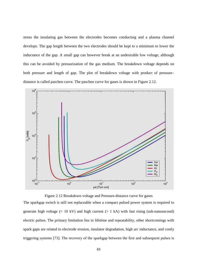
this can be avoided by pressurization of the gas medium. The breakdown voltage depends on
both pressure and length of gap.
distance is called paschen curve. The paschen curve for gases is shown in Figure
Figure 2.12 Breakdown voltage and P
The sparkgap switch is still not replaceable when a compact pulsed power
generate high voltage (> 10 kV) and high current (> 1 kA) with
electric pulses. The primary limitation lie
spark gaps are related to electrode erosio
triggering systems [73]. The recovery of the sparkgap between the
65
stress the insulating gas between the electrodes becomes conducting and a plasma channel
develops. The gap length between the two electrodes should be kept to a minimum to
inductance of the gap. A small gap can however break at an undesirable low voltage, although
this can be avoided by pressurization of the gas medium. The breakdown voltage depends on
both pressure and length of gap. The plot of breakdown voltage with product of pressure
distance is called paschen curve. The paschen curve for gases is shown in Figure
Breakdown voltage and Pressure-distance curve for gases
gap switch is still not replaceable when a compact pulsed power
generate high voltage (> 10 kV) and high current (> 1 kA) with fast rising (sub
limitation lies in lifetime and repeatability, other shortcomings with
related to electrode erosion, insulator degradation, high arc inductance, and
recovery of the sparkgap between the first and subsequent pulses is
stress the insulating gas between the electrodes becomes conducting and a plasma channel
develops. The gap length between the two electrodes should be kept to a minimum to lower the
inductance of the gap. A small gap can however break at an undesirable low voltage, although
this can be avoided by pressurization of the gas medium. The breakdown voltage depends on
with product of pressure–
distance is called paschen curve. The paschen curve for gases is shown in Figure 2.12.
curve for gases
gap switch is still not replaceable when a compact pulsed power system is required to
fast rising (sub-nanosecond)
ther shortcomings with
n, insulator degradation, high arc inductance, and costly
first and subsequent pulses is

66
a very important phenomenon in repetitive pulsed sparkgaps operation [74]. Pressurized
sparkgaps switches with hydrogen gas and pressure up to 120 kg/cm2 has been used for fast
switching up to 100 ps for ultra wide band generation [75]. Moran et. al [76 - 77] describes a
high repetition rate hydrogen sparkgap operating at pressures upto 7 MPa and 0.1 mm to 10 mm
gap. In a triggatron mode, a recovery time of 100 µs has been obtained. Faster recovery times
have been reported when the sparkgap was operated well below the self BDV. Recovery times
lower by an order of magnitude can be obtained by operating the sparkgap below fifty percent of
self BDV. The recovery time of hydrogen is slower at low pressure by an order of magnitude
compared to argon, it is an order of magnitude faster at very high pressure. The recovery of a
mixture of hydrogen and argon falls between the curves for separated gases. Experiments of fast
recovery of hydrogen gas switch were also conducted on a 600 kV, 10 µs, 5 pulse, and 10 kHz
burst mode pulse power system.
Semiconductor switches are used for fast switching fast switching but it is limited by its power
handling capacities. These switches have become popular owing to their compactness, better
service time, efficiency and reliability over other switches in their operational regime.
2.7 Summary
The literature update and research issues in the development of compact pulsed power
technology is discussed. The sub-systems required for the generation of high power pulse are
also discussed. To develop compact pulsed power technology, the combined research efforts are
required at component levels, system level and application level. The new components of the
pulsed power system could be developed using new high energy density materials such as
ceramics. The system level research leads to the investigation of novel architectural technique to
reduce the size of the pulsed power system.