chapter 12 flashing beacon planoregon department of transportation 12-8 january 2020 traffic...
TRANSCRIPT
2020 Traffic Signal Design Manual
Oregon Department of Transportation 12-i January 2020 Traffic Standards and Asset Management Unit Chapter 12 – Flashing Beacon Plan
Chapter 12 FLASHING BEACON PLAN
Contents
12 FLASHING BEACON PLAN ....................................................................................................... 12-1 12.1 Operational and Design Approval ............................................................................................... 12-2 12.2 Power Source .............................................................................................................................. 12-3 12.3 Beacon Operation ....................................................................................................................... 12-4 12.4 Warning Beacon .......................................................................................................................... 12-5
12.4.1 Warning Beacons for Obstructions ................................................................................................. 12-5 12.4.2 Warning Beacons for Warning Signs (Continuous Operation) ....................................................... 12-7 12.4.3 Warning Beacons for Ramp Meter Signs ........................................................................................ 12-8 12.4.4 Actuated Warning Beacons – Bridges ............................................................................................. 12-9 12.4.5 Actuated Warning Beacon – Tunnels ........................................................................................... 12-10 12.4.6 Actuated Warning Beacon – PREPARE TO STOP WHEN LIGHTS FLASH system ............................ 12-12 12.4.7 Actuated Warning Beacon – Mid-block Crosswalks ..................................................................... 12-14 12.4.8 Actuated Warning Beacon – Emergency Vehicles ........................................................................ 12-15
12.5 Rectangular Rapid Flashing Beacon (RRFB) .............................................................................. 12-16 12.5.1 MUTCD Interim Approval ............................................................................................................. 12-16 12.5.2 Device Assembly Requirements ................................................................................................... 12-16 12.5.3 Location of Assemblies ................................................................................................................. 12-16 12.5.4 Advance Sign Assemblies .............................................................................................................. 12-17
12.6 Speed Limit Sign Beacon ........................................................................................................... 12-18 12.7 Stop Sign Beacon ....................................................................................................................... 12-19 12.8 Intersection Control Beacon ..................................................................................................... 12-20 12.9 Pedestrian Hybrid Beacon ......................................................................................................... 12-24
12.9.1 Signal Indications .......................................................................................................................... 12-24 12.9.2 Controller and Service .................................................................................................................. 12-25 12.9.3 Poles ............................................................................................................................................. 12-25 12.9.4 Striping and Signing ...................................................................................................................... 12-25

2020 Traffic Signal Design Manual
Oregon Department of Transportation 12-1 January 2020 Traffic Standards and Asset Management Unit Chapter 12 – Flashing Beacon Plan
12 FLASHING BEACON PLAN
This page intentionally left blank
2020 Traffic Signal Design Manual
Oregon Department of Transportation 12-2 January 2020 Traffic Standards and Asset Management Unit Chapter 12 – Flashing Beacon Plan
12.1 Operational and Design Approval
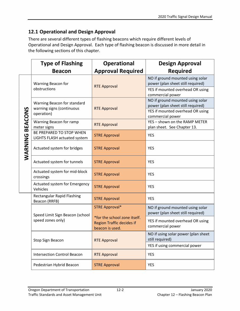
There are several different types of flashing beacons which require different levels of Operational and Design Approval. Each type of flashing beacon is discussed in more detail in the following sections of this chapter.
Type of Flashing Beacon
Operational Approval Required
Design Approval Required
WA
RN
ING
BEA
CO
NS
Warning Beacon for obstructions
RTE Approval
NO if ground mounted using solar power (plan sheet still required)
YES if mounted overhead OR using commercial power
Warning Beacon for standard warning signs (continuous operation)
RTE Approval
NO if ground mounted using solar power (plan sheet still required)
YES if mounted overhead OR using commercial power
Warning Beacon for ramp meter signs
RTE Approval YES – shown on the RAMP METER plan sheet. See Chapter 13.
BE PREPARED TO STOP WHEN LIGHTS FLASH actuated system
STRE Approval YES
Actuated system for bridges STRE Approval YES
Actuated system for tunnels STRE Approval YES
Actuated system for mid-block crossings
STRE Approval YES
Actuated system for Emergency Vehicles
STRE Approval YES
Rectangular Rapid Flashing Beacon (RRFB)
STRE Approval YES
Speed Limit Sign Beacon (school speed zones only)
STRE Approval* *for the school zone itself. Region Traffic decides if beacon is used.
NO if ground mounted using solar power (plan sheet still required)
YES if mounted overhead OR using commercial power
Stop Sign Beacon RTE Approval
NO if using solar power (plan sheet still required)
YES if using commercial power
Intersection Control Beacon RTE Approval YES
Pedestrian Hybrid Beacon STRE Approval YES
2020 Traffic Signal Design Manual
Oregon Department of Transportation 12-3 January 2020 Traffic Standards and Asset Management Unit Chapter 12 – Flashing Beacon Plan
12.2 Power Source
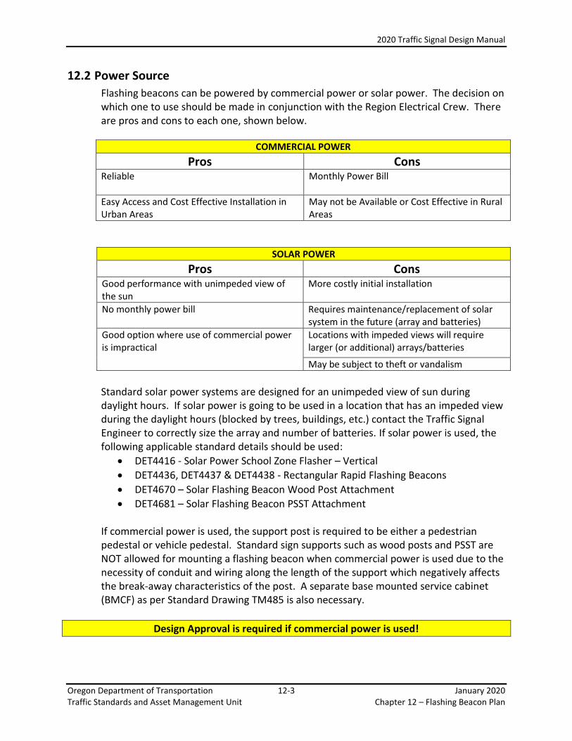
Flashing beacons can be powered by commercial power or solar power. The decision on which one to use should be made in conjunction with the Region Electrical Crew. There are pros and cons to each one, shown below.
COMMERCIAL POWER
Pros Cons Reliable
Monthly Power Bill
Easy Access and Cost Effective Installation in Urban Areas
May not be Available or Cost Effective in Rural Areas
SOLAR POWER
Pros Cons Good performance with unimpeded view of the sun
More costly initial installation
No monthly power bill
Requires maintenance/replacement of solar system in the future (array and batteries)
Good option where use of commercial power is impractical
Locations with impeded views will require larger (or additional) arrays/batteries
May be subject to theft or vandalism
Standard solar power systems are designed for an unimpeded view of sun during daylight hours. If solar power is going to be used in a location that has an impeded view during the daylight hours (blocked by trees, buildings, etc.) contact the Traffic Signal Engineer to correctly size the array and number of batteries. If solar power is used, the following applicable standard details should be used:
DET4416 - Solar Power School Zone Flasher – Vertical
DET4436, DET4437 & DET4438 - Rectangular Rapid Flashing Beacons
DET4670 – Solar Flashing Beacon Wood Post Attachment
DET4681 – Solar Flashing Beacon PSST Attachment If commercial power is used, the support post is required to be either a pedestrian pedestal or vehicle pedestal. Standard sign supports such as wood posts and PSST are NOT allowed for mounting a flashing beacon when commercial power is used due to the necessity of conduit and wiring along the length of the support which negatively affects the break-away characteristics of the post. A separate base mounted service cabinet (BMCF) as per Standard Drawing TM485 is also necessary.
Design Approval is required if commercial power is used!
2020 Traffic Signal Design Manual
Oregon Department of Transportation 12-4 January 2020 Traffic Standards and Asset Management Unit Chapter 12 – Flashing Beacon Plan
12.3 Beacon Operation
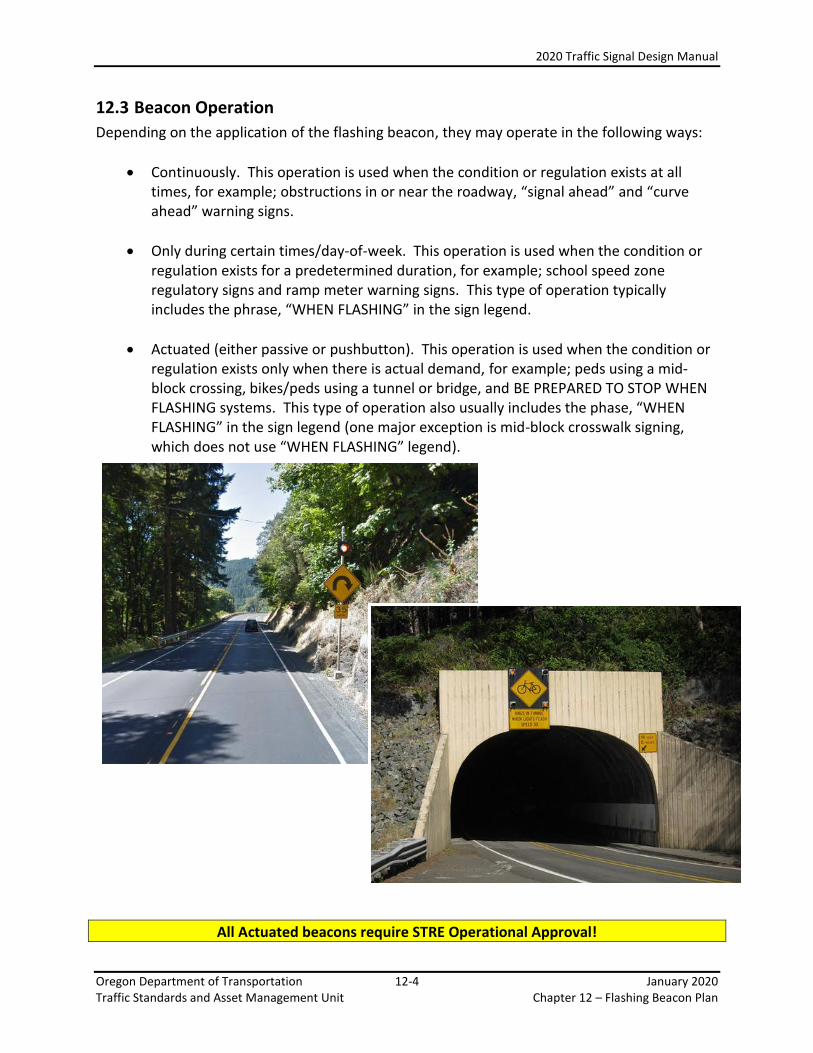
Depending on the application of the flashing beacon, they may operate in the following ways:
Continuously. This operation is used when the condition or regulation exists at all times, for example; obstructions in or near the roadway, “signal ahead” and “curve ahead” warning signs.
Only during certain times/day-of-week. This operation is used when the condition or regulation exists for a predetermined duration, for example; school speed zone regulatory signs and ramp meter warning signs. This type of operation typically includes the phrase, “WHEN FLASHING” in the sign legend.
Actuated (either passive or pushbutton). This operation is used when the condition or regulation exists only when there is actual demand, for example; peds using a mid-block crossing, bikes/peds using a tunnel or bridge, and BE PREPARED TO STOP WHEN FLASHING systems. This type of operation also usually includes the phase, “WHEN FLASHING” in the sign legend (one major exception is mid-block crosswalk signing, which does not use “WHEN FLASHING” legend).
All Actuated beacons require STRE Operational Approval!

2020 Traffic Signal Design Manual
Oregon Department of Transportation 12-5 January 2020 Traffic Standards and Asset Management Unit Chapter 12 – Flashing Beacon Plan
12.4 Warning Beacon
A warning beacon provides supplemental emphasis for appropriate warning or regulatory signs or markers. See MUTCD Section 4L.03 for more information. The following subsections list the common types of warning beacon used on the state highway. Warning beacons are generally ground mounted, but they may be mounted overhead for greater conspicuity.
12.4.1 Warning Beacons for Obstructions
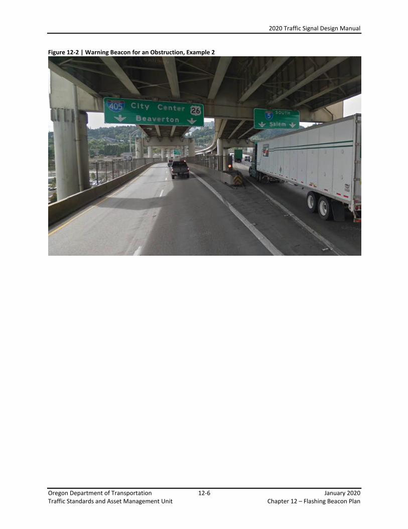
On the state highway, warning beacons are typically only used to emphasize one type of obstruction: impact attenuators located within the gore area of highway bifurcations. For this application, two vertically oriented, 12 inch circular yellow indications (custom signal head type) are mounted on a vehicle pedestal. The bottom of the signal backplate shall be 7 feet minimum above the roadway surface. The pedestal should be located behind the impact attenuator.
Figure 12-1 | Warning Beacon for an Obstruction, Example 1
2020 Traffic Signal Design Manual
Oregon Department of Transportation 12-6 January 2020 Traffic Standards and Asset Management Unit Chapter 12 – Flashing Beacon Plan
Figure 12-2 | Warning Beacon for an Obstruction, Example 2

2020 Traffic Signal Design Manual
Oregon Department of Transportation 12-7 January 2020 Traffic Standards and Asset Management Unit Chapter 12 – Flashing Beacon Plan
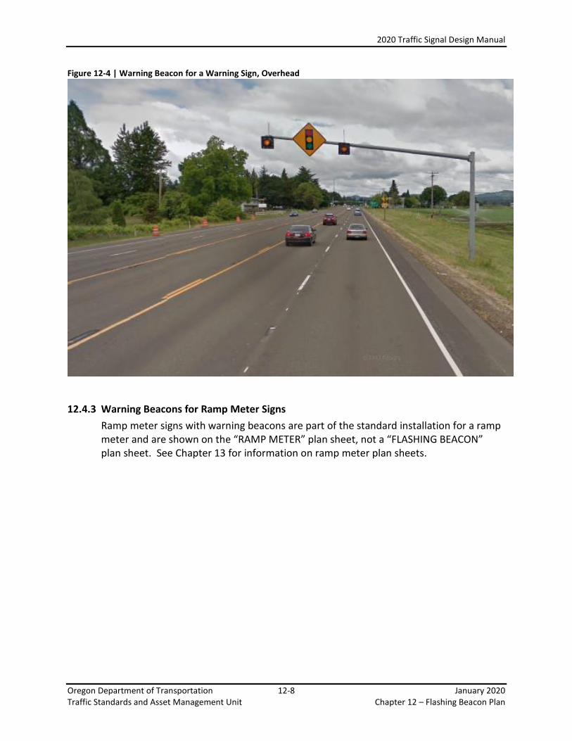
12.4.2 Warning Beacons for Warning Signs (Continuous Operation)
The common signs where warning beacons are used include:
Signal Ahead Signs
Curve Signs
Intersection Ahead Signs For post mounted applications, one Type 1Y signal head is mounted directly above the sign on the support post. If solar power is used, the support post may be either a standard wood pole or a Perforated Steel Square Tube (PSST). There are two standard details, DET4681 (PSST) and DET4670 (wood post) that should be used. If commercial power is used, the support post is required to be a vehicle pedestal. For overhead mounted applications, two Type 1Y signal heads are mounted on either side of the sign. A mast arm should be always be used if feasible. Clearances above the pavement are the same as for traffic signal heads, 18 feet minimum to 19 feet maximum.
Figure 12-3 | Warning Beacon for a Warning Sign, Post Mounted
2020 Traffic Signal Design Manual
Oregon Department of Transportation 12-8 January 2020 Traffic Standards and Asset Management Unit Chapter 12 – Flashing Beacon Plan
Figure 12-4 | Warning Beacon for a Warning Sign, Overhead
12.4.3 Warning Beacons for Ramp Meter Signs
Ramp meter signs with warning beacons are part of the standard installation for a ramp meter and are shown on the “RAMP METER” plan sheet, not a “FLASHING BEACON” plan sheet. See Chapter 13 for information on ramp meter plan sheets.

2020 Traffic Signal Design Manual
Oregon Department of Transportation 12-9 January 2020 Traffic Standards and Asset Management Unit Chapter 12 – Flashing Beacon Plan
12.4.4 Actuated Warning Beacons – Bridges
Actuated warning beacons for bridges consist of one Type 1Y signal head located above the warning sign. The warning sign legend should contain “WHEN FLASHING” text to inform the motorist of when the condition is applicable. For post mounted applications, one Type 1Y signal head is mounted directly above the sign on the support post. If solar power is used, the support post may be either a standard wood pole or a Perforated Steel Square Tube (PSST). There are two standard details, DET4681 (PSST) and DET4670 (wood post) that should be used. If commercial power is used, the support post is required to be a vehicle pedestal. For overhead mounted applications, two Type 1Y signal heads are mounted on either side of the sign using adjustable brackets (for a mast arm) or span wire hangers (for a span wire). A mast arm should be always be used if feasible. Clearances above the pavement are the same as for traffic signal heads, 18 feet minimum to 19 feet maximum. A pushbutton is the standard form of detection. Pushbuttons shall be provided according the requirements stated in Chapter 5, and located where they are easily accessible for all intended users (pedestrians and/or cyclists). Bridges are usually illuminated and therefore, commercial power for the actuated warning beacon system can typically be obtained from the illumination service cabinet. Work with the ODOT Bridge Section if any conduit or wiring for the actuated warning system needs to go across the structure. A custom control system using time-delay relays is used for these systems. Contact the Traffic Signal Engineer for assistance in designing the proper control system.
Figure 12-5 | Warning Beacon for a Warning Sign, Actuated Operation, Post Mounted

2020 Traffic Signal Design Manual
Oregon Department of Transportation 12-10 January 2020 Traffic Standards and Asset Management Unit Chapter 12 – Flashing Beacon Plan
12.4.5 Actuated Warning Beacon – Tunnels
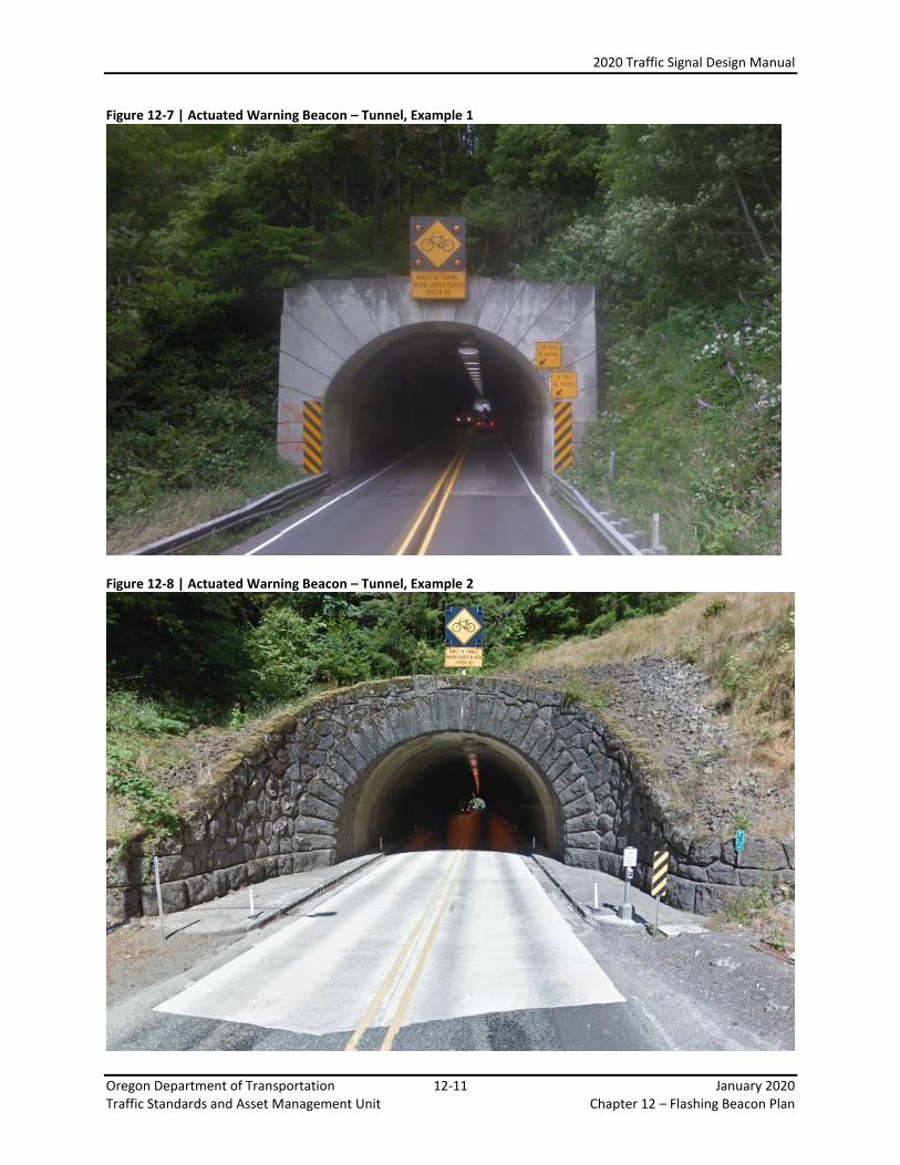
Actuated warning beacons for tunnels consists of an Oregon specific sign (OBW1-8) which has four 8 inch circular yellow indications within the sign boarder. See Figure 12-6 which shows sign OBW1-8 from the ODOT Sign Policy and Guidelines, Chapter 8. This sign assembly should be mounted overhead on the tunnel entrance, centered over the tunnel entrance. Ground mounted installations are not allowed. A push button is the standard form of detection. Pushbuttons shall be provided according the requirements stated in Chapter 5, and located where they are easily accessible for all intended users (pedestrians and/or cyclists). A custom control system using time-delay relays is used for these systems. Contact the Traffic Signal Engineer for assistance in designing the proper control system. Tunnels are always illuminated and therefore, commercial power for the actuated warning beacon system can typically be obtained from the illumination service cabinet.
Figure 12-6 | Actuated Warning Beacon – Tunnel Signing
2020 Traffic Signal Design Manual
Oregon Department of Transportation 12-11 January 2020 Traffic Standards and Asset Management Unit Chapter 12 – Flashing Beacon Plan
Figure 12-7 | Actuated Warning Beacon – Tunnel, Example 1
Figure 12-8 | Actuated Warning Beacon – Tunnel, Example 2

2020 Traffic Signal Design Manual
Oregon Department of Transportation 12-12 January 2020 Traffic Standards and Asset Management Unit Chapter 12 – Flashing Beacon Plan
12.4.6 Actuated Warning Beacon – PREPARE TO STOP WHEN LIGHTS FLASH system
PREPARE TO STOP WHEN LIGHTS FLASH warning beacons are typically used in advance of a traffic signal, or a special application thereof, such as for a location of roadway that has poor sight distance and experiences frequent back-ups. They are also commonly used for moveable bridges (See Chapter 23 for more information on Movable Bridges). PREPARE TO STOP WHEN LIGHTS FLASH warning beacons consist of an Oregon specific sign (OW15-14) with two Type 1Y signal heads located above the sign. See Figure 12-9 which shows sign OW15-14 from the ODOT Sign Policy and Guidelines, Chapter 4. This assembly should be mounted overhead centered over the travel lane(s).
Figure 12-9 | Actuated Warning Beacon – Queue Detection, Example1
Loop detection is the standard. Other forms of detection may considered (i.e. video, etc.) if deemed appropriate as per the guidance contained in chapter 6. The location of the detection and sign is critical to the proper operation of the beacons and is determined by an engineering study and documented in the STE Operational Approval. If this type of system is used in advance of a traffic signal, it needs to be connected to the traffic signal controller. If this type of system is NOT used in advance of a traffic signal, a custom control system using time-delay relays is used. Contact the Traffic Signal Engineer for assistance in designing the proper control system.

2020 Traffic Signal Design Manual
Oregon Department of Transportation 12-13 January 2020 Traffic Standards and Asset Management Unit Chapter 12 – Flashing Beacon Plan
Figure 12-10 | Warning Beacon Supplementing a Warning Sign, Passive Activation Operation, Overhead
2020 Traffic Signal Design Manual
Oregon Department of Transportation 12-14 January 2020 Traffic Standards and Asset Management Unit Chapter 12 – Flashing Beacon Plan
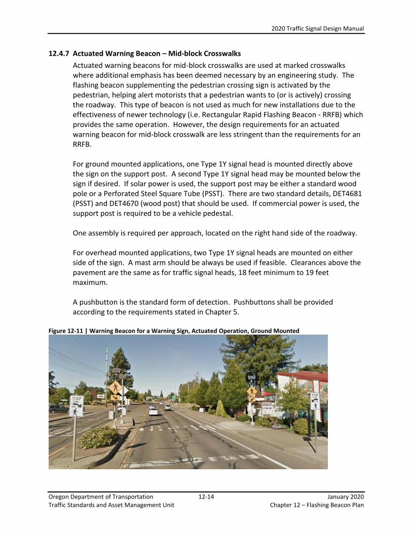
12.4.7 Actuated Warning Beacon – Mid-block Crosswalks
Actuated warning beacons for mid-block crosswalks are used at marked crosswalks where additional emphasis has been deemed necessary by an engineering study. The flashing beacon supplementing the pedestrian crossing sign is activated by the pedestrian, helping alert motorists that a pedestrian wants to (or is actively) crossing the roadway. This type of beacon is not used as much for new installations due to the effectiveness of newer technology (i.e. Rectangular Rapid Flashing Beacon - RRFB) which provides the same operation. However, the design requirements for an actuated warning beacon for mid-block crosswalk are less stringent than the requirements for an RRFB. For ground mounted applications, one Type 1Y signal head is mounted directly above the sign on the support post. A second Type 1Y signal head may be mounted below the sign if desired. If solar power is used, the support post may be either a standard wood pole or a Perforated Steel Square Tube (PSST). There are two standard details, DET4681 (PSST) and DET4670 (wood post) that should be used. If commercial power is used, the support post is required to be a vehicle pedestal. One assembly is required per approach, located on the right hand side of the roadway. For overhead mounted applications, two Type 1Y signal heads are mounted on either side of the sign. A mast arm should be always be used if feasible. Clearances above the pavement are the same as for traffic signal heads, 18 feet minimum to 19 feet maximum. A pushbutton is the standard form of detection. Pushbuttons shall be provided according to the requirements stated in Chapter 5.
Figure 12-11 | Warning Beacon for a Warning Sign, Actuated Operation, Ground Mounted

2020 Traffic Signal Design Manual
Oregon Department of Transportation 12-15 January 2020 Traffic Standards and Asset Management Unit Chapter 12 – Flashing Beacon Plan
12.4.8 Actuated Warning Beacon – Emergency Vehicles
Actuated warning beacon for emergency vehicles are a good alternative to traditional fire signals (described in Chapter 17). They are less expensive and provide an accurate, advance warning to drivers that they need to yield to an emergency vehicle accessing the roadway. For ground mounted applications, one Type 1Y signal head is mounted directly above the sign on the support post. A second Type 1Y signal head may be mounted below the sign if desired.
One assembly is required per approach, located on the right hand side of the roadway.
For overhead mounted applications, two Type 1Y signal heads are mounted on either side of the sign. A mast arm should be always be used if feasible. Clearances above the pavement are the same as for traffic signal heads, 18 feet minimum to 19 feet maximum. Contact the Traffic Signal Engineer for assistance in designing the proper control system.
Figure 12-12 | Warning Beacon for an Emergency Vehicle Sign, Actuated Operation, Ground Mounted
2020 Traffic Signal Design Manual
Oregon Department of Transportation 12-16 January 2020 Traffic Standards and Asset Management Unit Chapter 12 – Flashing Beacon Plan
12.5 Rectangular Rapid Flashing Beacon (RRFB)
A rectangular rapid flashing beacon is different from an actuated warning beacon for mid-block crosswalk discussed in Section 12.4.7. The RRFBs operation is the same, but it uses a unique shape and flash pattern to supplement a W11-2 (Pedestrian) or S1-1 (School) crossing warning sign with a diagonal downward arrow (W16-7p) plaque only. Due to the unique features, an RRFB has very specific design requirements that don’t apply a standard actuated warning beacon for a mid-block crosswalk.
12.5.1 MUTCD Interim Approval
The RRFB has been granted interim approval by FHWA. The signal designer should be familiar with the contents of the interim approval documentation, as some design elements have been specified. All of the design guidance provided in this chapter conforms to the FHWA interim approval requirements. The interim approval and subsequent official interpretations can be found on the MUTCD website at: http://mutcd.fhwa.dot.gov/res-interim_approvals.htm
12.5.2 Device Assembly Requirements
The interim approval contains requirements for the device assembly itself, such as dimensions, flash rate, and light intensity. The Traffic Signal Standards Unit has prequalified RRFB assemblies that meet the device requirements listed in the interim approval and listed them on the “Green Sheets” (see Chapter 20 for more information on the Green Sheets).
The Pedestrian Signal Plan Sheet must contain a note that states, “Use Green Sheet Listed Systems Only” to ensure that appropriate equipment is specified and installed.
In addition, a “Details” plan sheet will also be required using the appropriate drawings contained in Standard Details DET4436 thru DET4438. These standard details contain drawings for several different installations, including mounting options (pedestrian pedestal, signal pole, vehicle pedestal or mast arm), and use options (one sided or two sided assemblies). Foundation information for pedestal mounting is also included. See Chapter 9 and Chapter 17 for more information on “Details” plan sheets and standard details.
12.5.3 Location of Assemblies
RRFBs are located at or immediately adjacent to an uncontrolled, marked crosswalk. For each approach on which RRFBs are used, two assemblies are required, one on the right-hand side of the roadway and one on the left-hand side of the roadway. On a divided highway or a roadway with a median island pedestrian refuge, the left hand side assembly should be installed in the median. The assemblies should be located at or immediately adjacent to the marked crosswalk.

2020 Traffic Signal Design Manual
Oregon Department of Transportation 12-17 January 2020 Traffic Standards and Asset Management Unit Chapter 12 – Flashing Beacon Plan
12.5.4 Advance Sign Assemblies
Advance sign assemblies may be required if sight distance is not adequate to the crosswalk where the RRFBs are used. This requirement, if necessary, will be contained in the Operational Approval. These advance sign assemblies shall be activated and cease operation simultaneously with the RRFBs at the crosswalk location.
2020 Traffic Signal Design Manual
Oregon Department of Transportation 12-18 January 2020 Traffic Standards and Asset Management Unit Chapter 12 – Flashing Beacon Plan
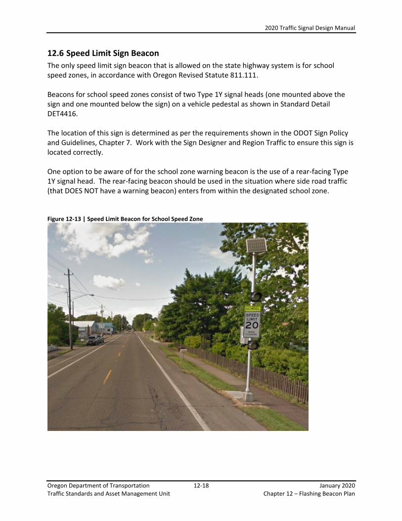
12.6 Speed Limit Sign Beacon
The only speed limit sign beacon that is allowed on the state highway system is for school speed zones, in accordance with Oregon Revised Statute 811.111. Beacons for school speed zones consist of two Type 1Y signal heads (one mounted above the sign and one mounted below the sign) on a vehicle pedestal as shown in Standard Detail DET4416.
The location of this sign is determined as per the requirements shown in the ODOT Sign Policy and Guidelines, Chapter 7. Work with the Sign Designer and Region Traffic to ensure this sign is located correctly.
One option to be aware of for the school zone warning beacon is the use of a rear-facing Type 1Y signal head. The rear-facing beacon should be used in the situation where side road traffic (that DOES NOT have a warning beacon) enters from within the designated school zone. Figure 12-13 | Speed Limit Beacon for School Speed Zone
2020 Traffic Signal Design Manual
Oregon Department of Transportation 12-19 January 2020 Traffic Standards and Asset Management Unit Chapter 12 – Flashing Beacon Plan
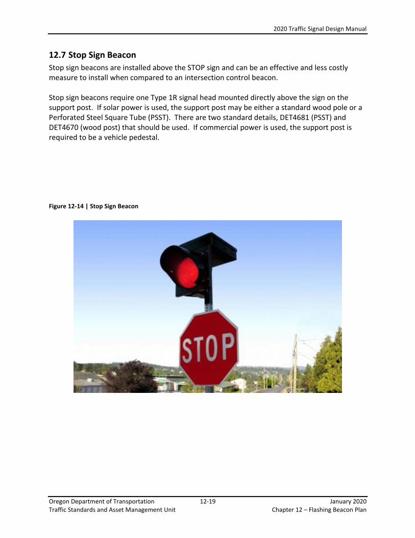
12.7 Stop Sign Beacon
Stop sign beacons are installed above the STOP sign and can be an effective and less costly measure to install when compared to an intersection control beacon. Stop sign beacons require one Type 1R signal head mounted directly above the sign on the support post. If solar power is used, the support post may be either a standard wood pole or a Perforated Steel Square Tube (PSST). There are two standard details, DET4681 (PSST) and DET4670 (wood post) that should be used. If commercial power is used, the support post is required to be a vehicle pedestal.
Figure 12-14 | Stop Sign Beacon
2020 Traffic Signal Design Manual
Oregon Department of Transportation 12-20 January 2020 Traffic Standards and Asset Management Unit Chapter 12 – Flashing Beacon Plan
12.8 Intersection Control Beacon
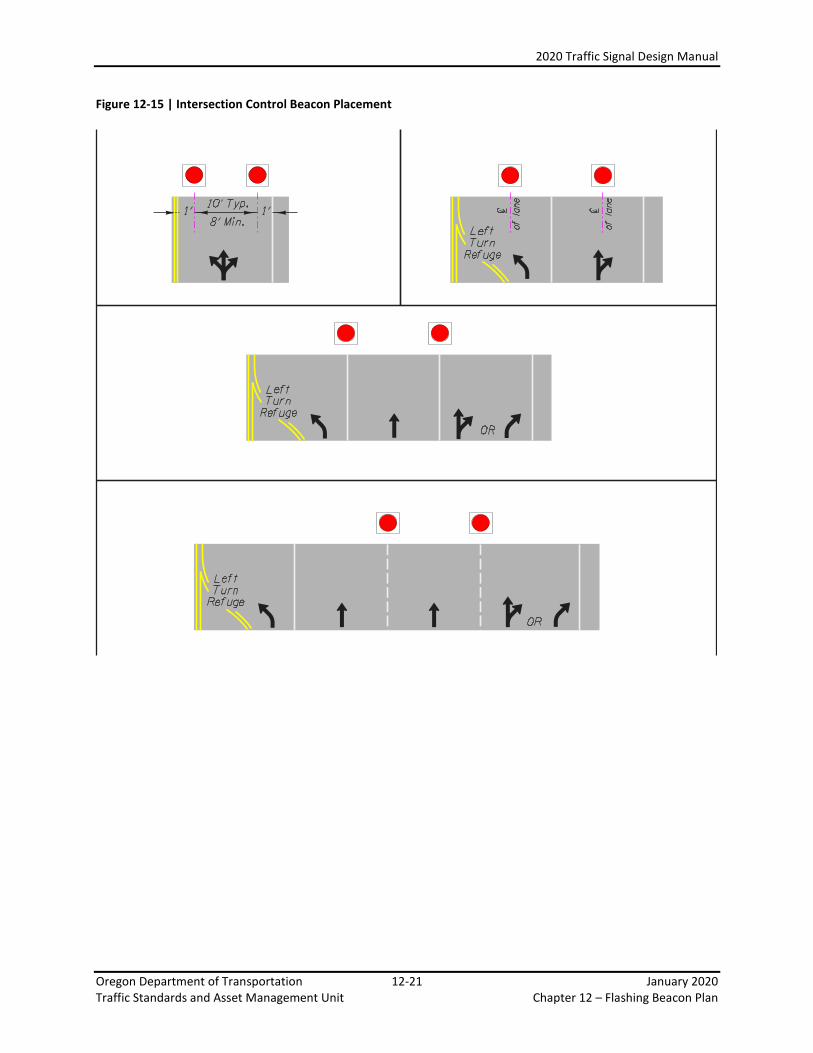
Intersection Control Beacons are used at intersections to supplement the traffic control at the intersection. They are typically used if visibility of the intersection is poor or the type of intersection control is not readily apparent. Intersection control beacons are always mounted overhead. Standard practice is to mount the flashing beacons on a mast arm pole. The beacons for all directions can then be mounted on a single mast arm. Strain poles and span wires can also be used if the intersection is too wide to be accommodated by a mast arm pole. Mast arm poles can be placed with arms oriented diagonally across the intersection. This may help to place the heads as close to the center of the intersection as possible. If strain poles are used, standard practice is to place two strain poles at opposite corners (diagonally) across the intersection. A tether cable is not required for flashing beacon installations. Intersection control beacons typically have beacons that face each approach of the intersection. However, there may be cases where only the mainline approaches or only the side street approaches have beacons, as determined by the engineering study documented in the RTE Operational Approval. Each approach requiring beacons shall have 2 beacons:
Type 1Y signal heads for free flow operation
Type 1R signal heads for stop controlled operation The red indication for stop controlled operations is only supplemental a STOP sign and therefore a STOP sign is required on each approach having a red flashing beacon. Flashing yellow indications shall not face conflicting vehicular approaches.
Clearances above the pavement are the same as for traffic signal heads, 18 feet minimum to 19 feet maximum. Lateral placement of the beacons should be as shown in Figure 12-15. A Base Mounted Cabinet with Flasher option (BMCF) controls the operation. See Standard Drawing TM485 for the wiring diagram. ODOT uses a Model 204 Flasher, which provides two alternating flash circuits. Beacons are wired with one 7-conductor No. 14 AWG control cable for each direction (flash circuit).
2020 Traffic Signal Design Manual
Oregon Department of Transportation 12-21 January 2020 Traffic Standards and Asset Management Unit Chapter 12 – Flashing Beacon Plan
Figure 12-15 | Intersection Control Beacon Placement
2020 Traffic Signal Design Manual
Oregon Department of Transportation 12-22 January 2020 Traffic Standards and Asset Management Unit Chapter 12 – Flashing Beacon Plan
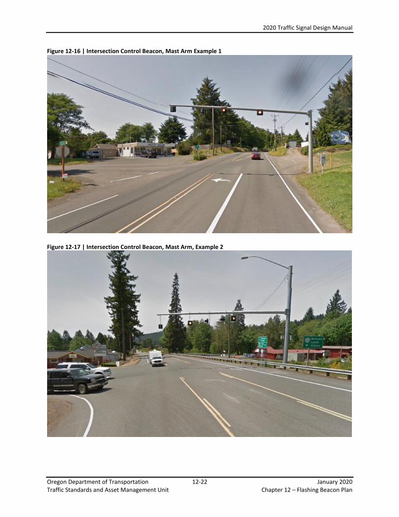
Figure 12-16 | Intersection Control Beacon, Mast Arm Example 1
Figure 12-17 | Intersection Control Beacon, Mast Arm, Example 2
2020 Traffic Signal Design Manual
Oregon Department of Transportation 12-23 January 2020 Traffic Standards and Asset Management Unit Chapter 12 – Flashing Beacon Plan
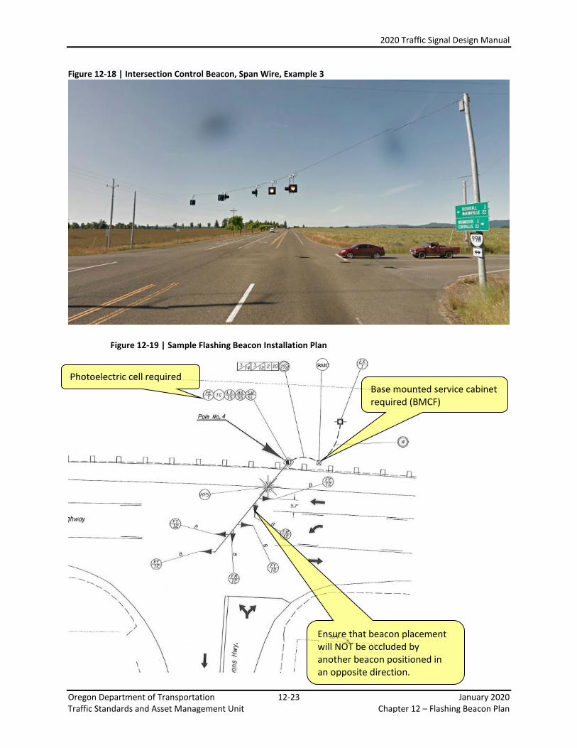
Figure 12-18 | Intersection Control Beacon, Span Wire, Example 3
Figure 12-19 | Sample Flashing Beacon Installation Plan
Photoelectric cell required Base mounted service cabinet required (BMCF)
Ensure that beacon placement will NOT be occluded by another beacon positioned in an opposite direction.
BMCF
2020 Traffic Signal Design Manual
Oregon Department of Transportation 12-24 January 2020 Traffic Standards and Asset Management Unit Chapter 12 – Flashing Beacon Plan
12.9 Pedestrian Hybrid Beacon
A pedestrian hybrid beacon is a special type of beacon that is used to both warn and control traffic at an unsignalized location to help pedestrians cross the roadway. See Chapter 4F of the MUTCD. To date, only one pedestrian hybrid beacon has been installed on the state highway system during the experimental phase, predating the 2009 MUTCD guidance.
A pedestrian hybrid beacon should NOT be installed within 100 feet of a side street or driveway controlled by a STOP or YIELD sign.
12.9.1 Signal Indications
Two type 10 signal heads are required per approach. These can be installed overhead or ground mounted depending on the site conditions. Overhead placement of both type 10 signal heads is required for the following conditions:
o the posted speed is greater than 35 mph o the posted speed is 35 mph or less on a two-way facility and there is NOT
a median of sufficient width o the approach has 3 or more lanes o where traffic or operating conditions may obscure visibility of a
ground mounted installation
If the heads are ground mounted on a two-way facility, a median island of sufficient width (6 feet or greater) is required to accommodate proper placement of the signal head located on the left-hand side of approaching traffic. If the approach has 3 or more lanes, a type 10 signal head centered in each lane is required. Pedestrian signal indications and push buttons shall be provided according to the requirements stated in Chapter 5.

2020 Traffic Signal Design Manual
Oregon Department of Transportation 12-25 January 2020 Traffic Standards and Asset Management Unit Chapter 12 – Flashing Beacon Plan
Figure 12-20 | Overhead Placement of Type 10 Signal Heads
12.9.2 Controller and Service
Pedestrian hybrid beacons use a standard base mounted service cabinet and 332S signal controller cabinet with a 2070 controller.
12.9.3 Poles
If mounted overhead, standard mast arm poles should be used. If ground mounted, vehicle pedestals should be used.
12.9.4 Striping and Signing
Pedestrian hybrid beacons require a marked crosswalk with a stop line installed at least 45 feet in advance. A minimum of one CROSSWALK STOP ON RED (R10-23) sign per approach shall be mounted adjacent to the type 10 signal head.

2020 Traffic Signal Design Manual
Oregon Department of Transportation 12-26 January 2020 Traffic Standards and Asset Management Unit Chapter 12 – Flashing Beacon Plan
Figure 12-21 | Pedestrian Hybrid Beacon – Overhead Mounted, Example 1
Figure 12-22 | Pedestrian Hybrid Beacon – Ground Mounted, Example 2
Note: This installation was installed when PHB’s were still experimental, before guidance on proximity to intersections was established.