vanguard fts 370i led integrated beacon · fts 370i revision 5 –8/18/2016 1 section 1 -overview...
TRANSCRIPT

Flash Technology, 332 Nichol Mill Lane, Franklin, TN 37067 www.flashtechnology.com
(615) 261-2000
VANGUARD® FTS 370i LED Integrated Beacon
Red LED Obstruction Lighting System Reference Manual
Part Number F7913701
SERIAL NUMBER

ii Revision 5 –8/18/2016 FTS 370i

REVISION DATE: June 13, 2014
ORIGINAL ISSUE DATE: May 19, 2014
Recertification due: August 2020
An Activity Sponsored and Administered by Intertek
PROGRAM ADMINISTRATOR DEPARTMENT ALECP INTERTEK 3933 U.S. ROUTE 11 CORTLAND, NY 13045-0950 FLASH TECHNOLOGY 332 Nichol Mill Lane Franklin, TN 37067
AIRPORT LIGHTING EQUIPMENT
CERTIFICATION PROGRAM
CERTIFICATE OF CONFORMANCE
The product described below is hereby approved for listing in the next issue of the Federal Aviation Administration (FAA) Advisory Circular (AC) 150/5345-53, Appendix 3 Addendum "Airport Lighting Equipment Certification Program. The approval is based on successful completion of tests in accordance with the specifications listed in, and the requirements for approval described in the Advisory Circular, and the reporting to the Program Administrator the results of such tests, accompanied by related documents by an Intertek recognized testing laboratory. This Certificate is only confirmable in conjunction with equipment being listed in AC 150/5345-53, Appendix 3, Addendum, as currently published by the FAA. The certification is not valid for a product modified with non-OEM replacement parts or non-production components.
L-864(L) – Lights, Obstruction, Red, 20-40 FPM (AC 150/5345-43G)
Manufacturer Manufacturer's Catalog Number
Flash Technology
FTS 370i (595) FTS 370i IR (595)
NOTE: (595) 1370175 LED Equipment meets the requirements of FAA Engineering Brief No. 67D additional requirements for “Light Sources Other Than Incandescent and Xenon for Airport and Obstruction Lighting Fixtures” dated March 6, 2012. 1. This Equipment requires continuing validation in accordance with the requirements of AC 150/5345-53,
and the Intertek Airport Lighting Equipment Certification Program. 2. Product tested and Report issued by: Intertek (A) Report No: 100836421CRT-001; 100856769CRT-001; 101527708CRT-001; 101527708MIN-008
(B) Date of Report: 10/2012; 9/2012; 4/2014; 4/2014
NOTE: PLEASE REVIEW, AND ADVISE ADMINISTRATOR AT INTERTEK IMMEDIATELY IF DATA, AS SHOWN, NEED TO BE CORRECTED.
Approved for Certification by:
Jeremy N Downs, P.E., Program Administrator Date: June 13, 2014
Form AL-3 1/2006

C e r t i f i c a t e : M a s t e r C o n t r a c t :P r o j e c t : D a t e I s s u e d :I s s u e d t o : F l a s h T e c h n o l o g y D i v i s i o n o fS P X C o r p o r a t i o n3 3 2 N i c h o l M i l l L nF r a n k l i n , T N 3 7 0 6 7U S AA t t e n t i o n : D a v i d D u r y e a
I s s u e d b y :P R O D U C T SC L A S S 3 4 2 5 8 5C L A S S 3 4 2 5 0 5A P P L I C A B L E R E Q U I R E M E N T S

www.intertek.com GFT-OP-11a (1-JUL-2012)
Test Verification of Conformity
Applicant Name & Address : Flash Technology
332 Nichol Mill Lane Franklin, TN 37067
Product(s) Tested : Medium-intensity, Type B Obstacle Light (Red)
Ratings and principal characteristics : 120-240Vac, Red, LED, 20 FPM
Model(s) : FTS370i and FTS 370i IR
Brand name : Flash Technology Vanguard LED Series
Relevant Standard(s)/Specification(s) : International Civil Aviation Organization (ICAO), Aerodromes, Annex 14, Volume 1, Sixth Edition, dated July 2013
Photometric – : Table 6-1 and Table 6-3 (requirements, not recommendations)
Chromaticity – Appendix 1 Sec. 2.1.1
Verification Issuing Office Name & Address
: Intertek Cortland – Lighting 3933 US Route 11 Cortland, NY 13045
Date of Test(s) : April 4, 2014 through April 8, 2014
Verification/Report Number(s) : 101527708CRT-001
NOTE : This verification is part of the full test report(s) and should be read in conjunction with it.
Signature Name: Jeremy N. Downs P.E Position: Staff Engineer Original Issue Date: July 30, 2014
On the basis of the tests undertaken, the sample(s) of the below product have been found to comply with the requirements of the referenced specifications at the time the tests were carried out.
This Verification is for the exclusive use of Intertek's Client and is provided pursuant to the agreement between Intertek and its Client. Intertek's responsibility and liability are limited to the terms and conditions of the agreement. Intertek assumes no liability to any party, other than to the Client in accordance with the agreement, for any loss, expense or damage occasioned by the use of this Verification. Only the Client is authorized to copy or distribute this Verification. Any use of the Intertek name or one of its marks for the sale or advertisement of the tested material, product or service must first be approved in writing by Intertek. The observations and test results referenced from this Verification are relevant only to the sample tested. This Verification by itself does not imply that the material, product, or service is or has ever been under an Intertek certification program.
Intertek 3933 U.S. Rte. 11 Cortland, NY 13045 Phone: 607-753-6711 Fax: 607-758-6637
FTS 370i Revision 5 –8/18/2016 vii
Front Matter
Abstract
This manual contains information and instructions for installing, operating and maintaining the
FTS 370i, FTS 370i IR, FTS 370i ICAO, and FTS 370i IR ICAO LED Integrated Beacons.
Copyright
Copyright © 2016, Flash Technology®, Franklin, TN, 37067, U.S.A.
All rights reserved. Reproduction or use of any portion of this manual is prohibited without
express written permission from Flash Technology and/or its licenser.
Trademark Acknowledgements
Flash Technology® and Vanguard® are registered trademark names.
All trademarks and product names mentioned are properties of their respective companies and are
recognized and acknowledged as such by Flash Technology.
Applicable Specifications
The FTS 370i and FTS 370i IR beacons meet or exceed requirements for an FAA Type L-864
beacon. The FTS 370i ICAO and FTS 370i IR ICAO beacons meet or exceed requirements for an
ICAO Annex 14, Volume 1, 6th Edition Low Intensity Type B Obstacle Light.
Disclaimer
While every effort has been made to ensure that the information in this manual is complete,
accurate and up-to-date, Flash Technology assumes no liability for damages resulting from any
errors or omissions in this manual, or from the use of the information contained herein. Flash
Technology reserves the right to revise this manual without obligation to notify any person or
organization of the revision.
In no event will Flash Technology be liable for direct, indirect, special, incidental, or
consequential damages arising out of the use of or the inability to use this manual.
Warranty
Flash Technology warrants all components, under normal operating conditions, for 5 years.
Parts Replacement
The use of parts or components, in this equipment, not manufactured or supplied by Flash
Technology voids the warranty and invalidates the third party testing laboratory certification
which ensures compliance with FAA Advisory Circulars 150/5345-43G, 150/5345-53D, and
Engineering Brief No. 67D. The certification is valid as long as the system is maintained in
accordance with FAA guidelines (FR doc. 04-13718 filed 6-16-04).

viii Revision 5 –8/18/2016 FTS 370i
Personnel Hazard Warning
Dangerous Voltages
Dangerous line voltages reside in certain locations in this equipment. Also, this equipment may
generate dangerous voltages. Although Flash Technology has incorporated every practical safety
precaution, exercise extreme caution at all times when you expose circuits and components, and
when you operate, maintain, or service this equipment.
Avoid Touching Live Circuits
Avoid touching any component or any part of the circuitry while the equipment is operating. Do
not change components or make adjustments inside the equipment with power on.
Do Not Depend on Interlocks
Never depend on interlocks alone to remove unsafe voltages. Always check circuits with a
voltmeter after turning the circuit breakers off. Under no circumstances remove or alter the
wiring or interlock switches.

FTS 370i Revision 5 –8/18/2016 ix
Table of Contents
FAA Certificate of Conformance ..................................................................................................... iii CE Declaration of Conformity........................................................................................................... iv CSA Certificate of Compliance .......................................................................................................... v ICAO Test Verification of Conformity ............................................................................................. vi Front Matter ..................................................................................................................................... vii
Abstract ........................................................................................................................................ vii Copyright ..................................................................................................................................... vii Trademark Acknowledgements ................................................................................................... vii Applicable Specifications ............................................................................................................ vii Disclaimer .................................................................................................................................... vii
Warranty ...................................................................................................................................... vii Parts Replacement ....................................................................................................................... vii
Personnel Hazard Warning ............................................................................................................. viii
Dangerous Voltages .................................................................................................................... viii Avoid Touching Live Circuits .................................................................................................... viii Do Not Depend on Interlocks ..................................................................................................... viii
List of Figures ..................................................................................................................................... x
List of Tables ...................................................................................................................................... x Section 1 - Overview .......................................................................................................................... 1
1.1 Specifications ............................................................................................................................ 1 1.1.1 Regulatory Compliance and Certifications ........................................................................ 2
1.2 Beacon Component Identification ............................................................................................ 3
Section 2 – Installation – Mounting, Wiring, and Checkout .............................................................. 6 2.1 Mounting the Beacon ................................................................................................................ 6
2.2 Wiring the Beacon .................................................................................................................... 8
2.3 Verifying Operation .................................................................................................................. 9
2.3.1 Power up ............................................................................................................................ 9 2.3.2 Synchronization ................................................................................................................. 9
Section 3 - Operation ........................................................................................................................ 10 3.1 Status Indicator LEDs ............................................................................................................. 10 3.2 Configuration Jumpers ............................................................................................................ 11
Section 4 - Beacon Theory of Operation .......................................................................................... 12 4.1 System Overview .................................................................................................................... 12
Section 5 - Maintenance and Troubleshooting ................................................................................. 15
5.1 Maintenance ............................................................................................................................ 15 5.2 Troubleshooting ...................................................................................................................... 15 5.3 Beacon Repair Procedures ...................................................................................................... 16
5.3.1 Replace the Controller Core PCB .................................................................................... 16
5.3.2 Replace the Power Supply ............................................................................................... 17 5.3.3 Replace the GPS Antenna and Cable ............................................................................... 17 5.3.4 Replace the Surge Suppressors ........................................................................................ 18
5.3.5 Replace the LED Engine Assembly ................................................................................ 18 5.4 Customer Service .................................................................................................................... 21 5.5 Ordering Parts ......................................................................................................................... 21
Return Material Authorization (RMA) Policy .................................................................................. 22
x Revision 5 –8/18/2016 FTS 370i
List of Figures Figure 1-1 – Beacon - External View ............................................................................................... 3 Figure 1-2 – Beacon Base Assembly ................................................................................................ 4 Figure 1-3 – Beacon & Controller Assembly ................................................................................... 5 Figure 2-1 – Flashhead Dimensions & Mounting Outline ............................................................... 7 Figure 3-1 – Status Indicator LEDs ................................................................................................ 10
Figure 3-2 – Configuration Jumpers ............................................................................................... 11 Figure 4-1 – Beacon Wiring Diagram (Standard) .......................................................................... 13 Figure 4-2 – Beacon Wiring Diagram (10 Conductor Option) ....................................................... 14 Figure 5-1 – Beacon Component Locations ................................................................................... 19 Figure 5-2 – Base Component Locations ....................................................................................... 20
List of Tables
Table 2-1 – Standard Power & Alarm Connections ........................................................................... 8 Table 2-2 – Power, Alarm & Radar Interface Connections ................................................................ 8 Table 3-1 – Status Indicator LEDs ................................................................................................... 10 Table 3-2 – Configuration Jumpers .................................................................................................. 11 Table 5-1 – Troubleshooting - Beacon is in alarm ........................................................................... 15 Table 5-2 – Troubleshooting - Beacon does not flash at night ......................................................... 15
Table 5-3 – Troubleshooting - Beacon flashes but not in sync ........................................................ 16 Table 5-4 – Troubleshooting - Beacon flashes in daytime ............................................................... 16
Table 5-5 – Optional Parts ................................................................................................................ 21 Table 5-6 – Spare/Replacement Parts ............................................................................................... 21
FTS 370i Revision 5 –8/18/2016 1
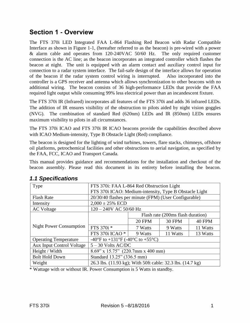
Section 1 - Overview
The FTS 370i LED Integrated FAA L-864 Flashing Red Beacon with Radar Compatible
Interface as shown in Figure 1-1, (hereafter referred to as the beacon) is pre-wired with a power
& alarm cable and operates from 120-240VAC 50/60 Hz. The only required customer
connection is the AC line; as the beacon incorporates an integrated controller which flashes the
beacon at night. The unit is equipped with an alarm contact and auxiliary control input for
connection to a radar system interface. The fail-safe design of the interface allows for operation
of the beacon if the radar system control wiring is interrupted. Also incorporated into the
controller is a GPS receiver and antenna which allows synchronization to other beacons with no
additional wiring. The beacon consists of 36 high-performance LEDs that provide the FAA
required light output while consuming 99% less electrical power than an incandescent fixture.
The FTS 370i IR (Infrared) incorporates all features of the FTS 370i and adds 36 infrared LEDs.
The addition of IR ensures visibility of the obstruction to pilots aided by night vision goggles
(NVG). The combination of standard Red (620nm) LEDs and IR (850nm) LEDs ensures
maximum visibility to pilots in all circumstances.
The FTS 370i ICAO and FTS 370i IR ICAO beacons provide the capabilities described above
with ICAO Medium-intensity, Type B Obstacle Light (Red) compliance.
The beacon is designed for the lighting of wind turbines, towers, flare stacks, chimneys, offshore
oil platforms, petrochemical facilities and other obstructions to aerial navigation, as specified by
the FAA, FCC, ICAO and Transport Canada.
This manual provides guidance and recommendations for the installation and checkout of the
beacon assembly. Please read this document in its entirety before installing the beacon.
1.1 Specifications
Type FTS 370i: FAA L-864 Red Obstruction Light
FTS 370i ICAO: Medium-intensity, Type B Obstacle Light
Flash Rate 20/30/40 flashes per minute (FPM) (User Configurable)
Intensity 2,000 ± 25% ECD
AC Voltage 120 – 240V AC 50/60 Hz
Night Power Consumption
Flash rate (200ms flash duration)
20 FPM 30 FPM 40 FPM
FTS 370i * 7 Watts 9 Watts 11 Watts
FTS 370i ICAO * 9 Watts 11 Watts 13 Watts
Operating Temperature -40°F to +131°F (-40°C to +55°C)
Aux Input Control Voltage 5 – 30 Volts AC/DC
Height / Width 8.69” x 15.75” (220.7mm x 400 mm)
Bolt Hold Down Standard 13.25” (336.5 mm)
Weight 26.3 lbs. (11.93 kg); With 50ft cable: 32.3 lbs. (14.7 kg)
* Wattage with or without IR. Power Consumption is 5 Watts in standby.

2 Revision 5 –8/18/2016 FTS 370i
1.1.1 Regulatory Compliance and Certifications
ETL Certified to Federal Aviation Administration (FAA): AC No. (150/5345-43G). FAA
Engineering Brief No. 67D
Compliant to Canadian Aviation Regulation (CAR): CAR 621.19
FTS 370i ICAO, FTS 370i IR ICAO: International Civil Aviation Organization (ICAO),
Aerodromes, Annex 14, Volume 1, Sixth Edition, dated July 2013
FTS 370i Revision 5 –8/18/2016 3
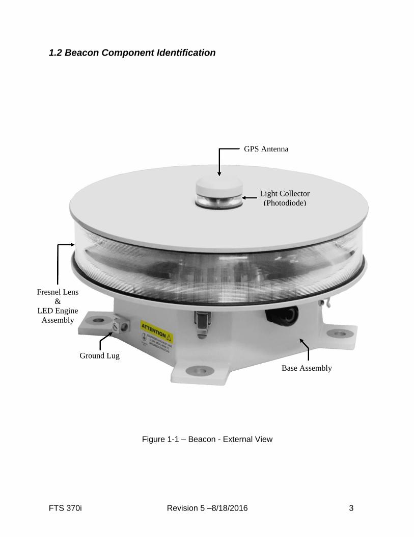
1.2 Beacon Component Identification
Figure 1-1 – Beacon - External View
GPS Antenna
Light Collector
(Photodiode)
Fresnel Lens
&
LED Engine
Assembly
Ground Lug
Base Assembly

4 Revision 5 –8/18/2016 FTS 370i
Figure 1-2 – Beacon Base Assembly
Power
Supply
Surge
Suppressors
TB1
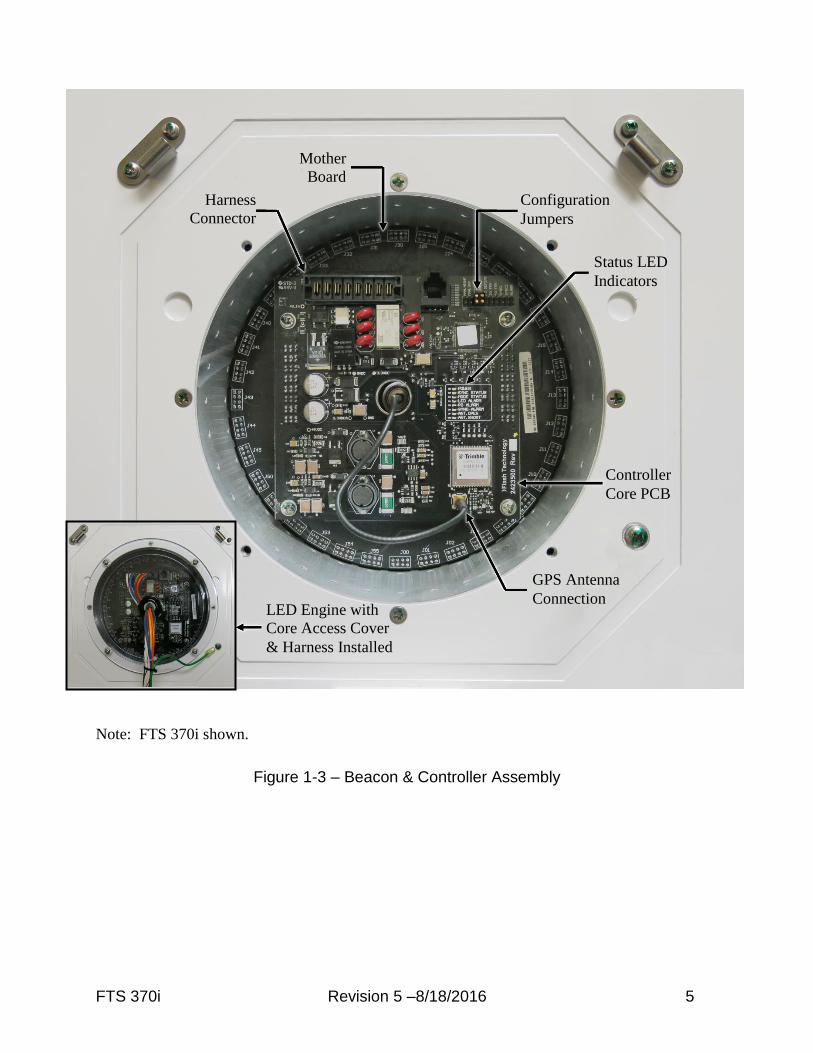
FTS 370i Revision 5 –8/18/2016 5
Note: FTS 370i shown.
Figure 1-3 – Beacon & Controller Assembly
Mother
Board
GPS Antenna
Connection
Harness
Connector
LED Engine with
Core Access Cover
& Harness Installed
Status LED
Indicators
Configuration
Jumpers
Controller
Core PCB
6 Revision 5 –8/18/2016 FTS 370i
Section 2 – Installation – Mounting, Wiring, and Checkout
Warning
Read the warning on page ix now. Remove power from all wiring and circuitry before installing
or performing work on the beacon. It is the responsibility of the installer to comply with all
applicable electrical codes.
Important!
For proper operation and optimal protection from Lighting and EMI, ensure that the base
is electrically bonded to the site grounding system using 8 AWG wire minimum connected
to the supplied external ground lug.
Flash Technology recommends the installation of one or more lightning rods near the
beacon. The copper lightning rod(s) should be located approximately 18 inches away from
and extend a minimum of three feet above the height of the beacon.
Installation Procedure:
1. Mount the beacon (Section 2.1) 2. Wire the beacon power (Section 2.2) 3. Verify operation (Section 2.3) 4. Wire the beacon monitoring connections (Section 2.2) 5. Confirm monitoring status by disconnecting power to the beacon. This should create an alarm. After all steps are completed successfully, the installation is complete.
2.1 Mounting the Beacon
Flash Technology recommends the installation of one or more lightning rods near the beacon.
The copper lightning rod(s) should be located approximately 18 inches away from and extend a
minimum of three feet above the height of the beacon.
The beacon should be positioned so that the light collector for the photodiode has an
unobstructed view of the polar sky. Also, it must not view direct or reflected artificial light. The
GPS antenna located on top of the beacon must have an unobstructed view of the sky for proper
reception and synchronization.
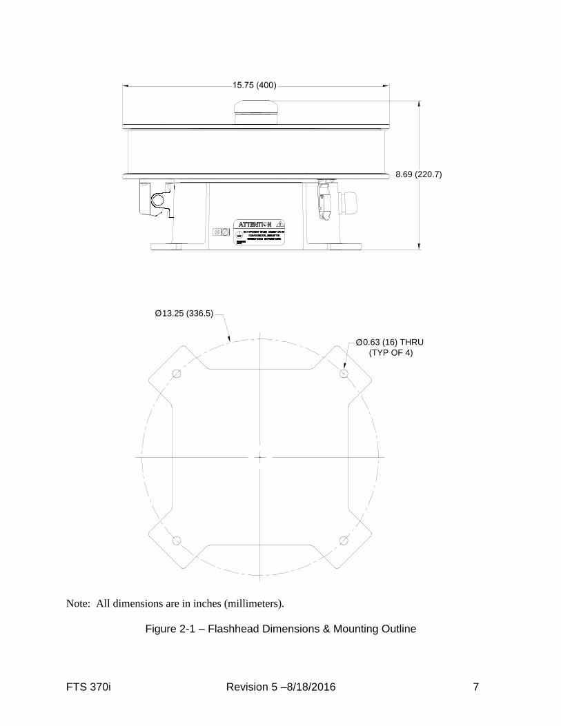
The beacon is mounted to the tower pedestal or optional mounting bracket1 utilizing supplied
hardware. Four mounting holes are provided on the beacon base (Figure 2-1). These mounting
holes will align with most tower pedestals. The beacon should be installed level to maintain light
output in accordance with FAA/ICAO requirements.
1. An optional mounting bracket is available to accommodate various installation configurations
and to facilitate leveling the beacon. See Section 5.5 for ordering information.
FTS 370i Revision 5 –8/18/2016 7
Note: All dimensions are in inches (millimeters).
Figure 2-1 – Flashhead Dimensions & Mounting Outline
13.25 (336.5)
0.63 (16) THRU
O
(TYP OF 4)
8.69 (220.7)
O

8 Revision 5 –8/18/2016 FTS 370i
2.2 Wiring the Beacon
The beacon is supplied with a 50 foot length of power & alarm cable pre-wired to the internal
electronics to facilitate installation (see Table 2-1). The only connections required are power
(120-240 VAC, 50/60 Hz) and ground. The ground wire must be connected for proper operation
and protection of the beacon.
Optional dry contact monitoring connections permit monitoring of beacon operation. The
contact is closed when the beacon is operating normally and no fault is detected.
The Auxiliary Control Input allows an external device, such as a radar system, to inhibit the
flashing of the beacon (see Table 2-2). The acceptable input voltage range for the Control Input
is 5 – 30 Volts AC/DC. The optional 10 conductor cable is required to utilize this feature.
Table 2-1 – Standard Power & Alarm Connections
5 C
on
du
ctor C
ab
le
Wire
Color
Function FTB 370i Beacon
Internal Connections
External
Connections
Black Input Power TB1 - L1 (120 VAC) - Line
(240 VAC) - L1
White Input Power TB1 - L2 (120 VAC) - Neutral
(240 VAC) – L2
Green Ground TB1 - GND Ground
Red Alarm Contact TB1 - COM Alarm Input1
Orange Alarm Contact TB1- NC Alarm Input1
Table 2-2 – Power, Alarm & Radar Interface Connections
10 C
on
du
ctor C
ab
le (Op
tion
al)
Wire
Color
Function FTB 370i Beacon
Internal Connections
External
Connections
Black Input Power TB1 - L1 (120 VAC) - Line
(240 VAC) - L1
White Input Power TB1 - L2 (120 VAC) - Neutral
(240 VAC) – L2
Green Ground TB1 - GND Ground
Red Alarm Contact TB1 - COM Alarm Input1
Orange Alarm Contact TB1- NC Alarm Input1
Brown Auxiliary Control Input TB1 – AUX - Control Output2
Blue Auxiliary Control Input TB1 - AUX + Control Output2
Violet Ground Chassis GND Ground
Yellow Ground Chassis GND Ground
Gray Ground Chassis GND Ground
Drain Ground Chassis GND Ground
1. Refer to the monitoring system manufacturer’s installation manual for connection locations.
2. Refer to the radar system manufacturer’s installation manual for connection locations.

FTS 370i Revision 5 –8/18/2016 9
2.3 Verifying Operation
Apply power to the beacon and verify operation as indicated by the beacon and Status Indicator
LEDs.
Note: See Section 3.1 for a description each Status Indicator LED,
2.3.1 Power up
When powered up, all indicator LEDs are turned on for 10 seconds providing easy verification of
operation. The beacon will begin flashing and will turn off after 40 seconds if the photodiode
detects sufficient light. Otherwise, the beacon will remain on until the ambient light rises to a
sufficient level.
2.3.2 Synchronization
For synchronization to occur, the GPS antenna (located on top of the beacon) must have an
unobstructed view of the sky. As much as 15 minutes may be required for the beacon to achieve
a GPS signal lock. Following power up, the Sync Alarm and Sync Status LEDs will turn off.
Once a GPS signal lock is achieved, the Sync Status LED will turn on. This is the normal
operating condition.
Note: After one hour of operation, the Sync Alarm will turn on if a GPS signal lock has not been achieved. The alarm will turn off once a GPS signal is locked. Refer to Section 5 if the Sync Alarm remains on for more than 15 minutes.
10 Revision 5 –8/18/2016 FTS 370i
Section 3 - Operation
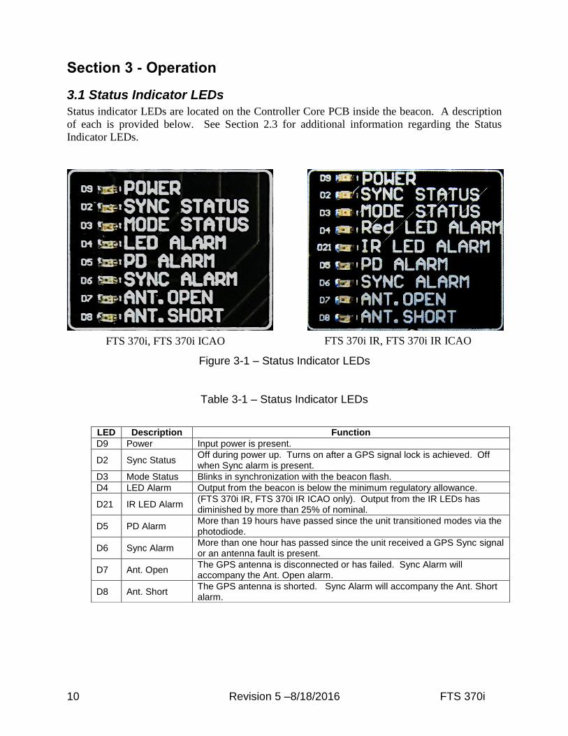
3.1 Status Indicator LEDs
Status indicator LEDs are located on the Controller Core PCB inside the beacon. A description
of each is provided below. See Section 2.3 for additional information regarding the Status
Indicator LEDs.
Figure 3-1 – Status Indicator LEDs
Table 3-1 – Status Indicator LEDs
LED Description Function
D9 Power Input power is present.
D2 Sync Status Off during power up. Turns on after a GPS signal lock is achieved. Off when Sync alarm is present.
D3 Mode Status Blinks in synchronization with the beacon flash.
D4 LED Alarm Output from the beacon is below the minimum regulatory allowance.
D21 IR LED Alarm (FTS 370i IR, FTS 370i IR ICAO only). Output from the IR LEDs has diminished by more than 25% of nominal.
D5 PD Alarm More than 19 hours have passed since the unit transitioned modes via the photodiode.
D6 Sync Alarm More than one hour has passed since the unit received a GPS Sync signal or an antenna fault is present.
D7 Ant. Open The GPS antenna is disconnected or has failed. Sync Alarm will accompany the Ant. Open alarm.
D8 Ant. Short The GPS antenna is shorted. Sync Alarm will accompany the Ant. Short alarm.
FTS 370i, FTS 370i ICAO FTS 370i IR, FTS 370i IR ICAO
FTS 370i Revision 5 –8/18/2016 11
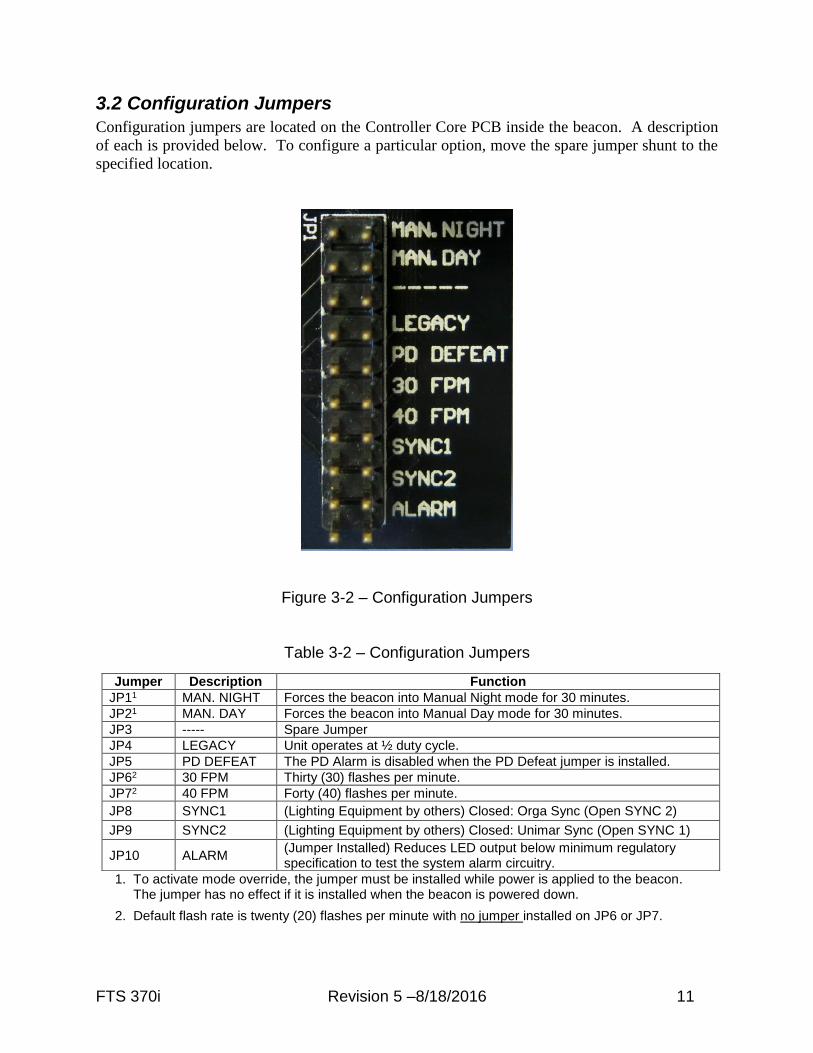
3.2 Configuration Jumpers
Configuration jumpers are located on the Controller Core PCB inside the beacon. A description
of each is provided below. To configure a particular option, move the spare jumper shunt to the
specified location.
Figure 3-2 – Configuration Jumpers
Table 3-2 – Configuration Jumpers
1. To activate mode override, the jumper must be installed while power is applied to the beacon. The jumper has no effect if it is installed when the beacon is powered down.
2. Default flash rate is twenty (20) flashes per minute with no jumper installed on JP6 or JP7.
Jumper Description Function
JP11 MAN. NIGHT Forces the beacon into Manual Night mode for 30 minutes.
JP21 MAN. DAY Forces the beacon into Manual Day mode for 30 minutes.
JP3 ----- Spare Jumper
JP4 LEGACY Unit operates at ½ duty cycle.
JP5 PD DEFEAT The PD Alarm is disabled when the PD Defeat jumper is installed.
JP62 30 FPM Thirty (30) flashes per minute.
JP72 40 FPM Forty (40) flashes per minute.
JP8 SYNC1 (Lighting Equipment by others) Closed: Orga Sync (Open SYNC 2)
JP9 SYNC2 (Lighting Equipment by others) Closed: Unimar Sync (Open SYNC 1)
JP10 ALARM (Jumper Installed) Reduces LED output below minimum regulatory specification to test the system alarm circuitry.
12 Revision 5 –8/18/2016 FTS 370i
Section 4 - Beacon Theory of Operation
4.1 System Overview
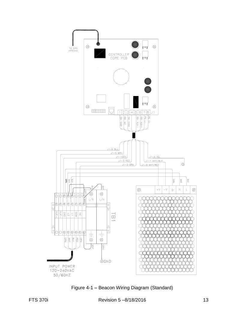
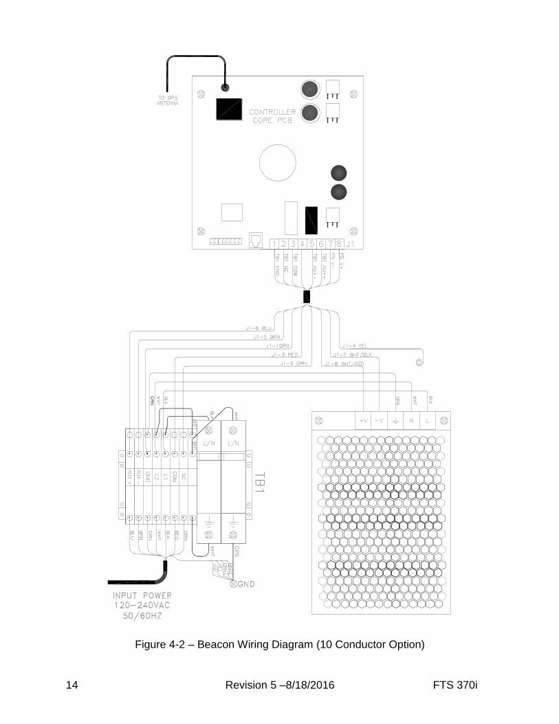
The beacon wiring diagrams are shown in Figures 4-1 and 4-2. The standard five conductor
power & alarm cable, shown in figure 4-1, provides connection of the AC line (3 wires) and
alarm monitoring connections (2 wires). The optional ten conductor cable, shown in Figure 4-2,
provides the same connections and adds connections for the auxiliary control input (2 wires).
The remaining 3 conductors and drain wire are connected to chassis ground.
The AC line may be 120-240VAC 50/60Hz. The dry contact alarm connections are closed when
the beacon is operating normally and no fault is detected. The voltage range for auxiliary control
input is 5 – 30 Volts AC/DC. The beacon flash will be inhibited when voltage within the
specified range is applied to the terminals labeled AUX + and AUX -.
The Controller Core PCB (370i 2423500 / 370i IR 2423600 / 370i ICAO 2423501 / 370i IR
ICAO 2423601) senses ambient light focused by the light collector onto the photodiodes and at
night flashes the LED beacon. A GPS antenna and integrated receiver permit synchronization to
other beacons. The Controller Core PCB detects alarm conditions including beacon failure,
photodiode alarm, and synchronization fault. A clear polycarbonate cover provides access to
view the status and alarm LEDs to permit easy determination of proper operation and fault
diagnosis.
The LED Engine assembly contains high-performance LEDs which illuminate when powered by
the Controller Core PCB. The complete assembly (370i 1370180 / 370i IR 1370175 / 370i
ICAO 1370280 / 370i IR ICAO 1370275) is easily replaced when field service is required.
The Power Supply (5150501) and the Surge Suppressors (11000010290) are located in the base
of the beacon. The power supply generates the proper DC current to the Controller Core PCB
when AC line voltage is applied at its input. The surge suppressors, wired in line with and
directly across the AC Line, provide protection from incoming lightning and transient voltage
induced surges.
FTS 370i Revision 5 –8/18/2016 13
Figure 4-1 – Beacon Wiring Diagram (Standard)
14 Revision 5 –8/18/2016 FTS 370i
Figure 4-2 – Beacon Wiring Diagram (10 Conductor Option)

FTS 370i Revision 5 –8/18/2016 15
Section 5 - Maintenance and Troubleshooting
5.1 Maintenance
No regularly scheduled maintenance is required for the beacon.
Flash Technology warranties the light output of the beacon to meet or exceed FAA/ICAO
requirements for a 5 year period. LED module replacement after 5 years is recommended
to ensure FAA/ICAO compliance. See Section 5.3.3.
Periodically check the GPS antenna for tightness.
Periodic cleaning of the lens is recommended with soapy water or any acrylic cleaning
solution. No other cleaning solutions are recommended. Abrasive compounds will scratch
the lens.
Optional mounting brackets should be checked periodically for tightness.
5.2 Troubleshooting
Follow the troubleshooting steps in the tables below as applicable. Beacon repair procedures are
provided in Section 5.3.
Table 5-1 – Troubleshooting - Beacon is in alarm Step Check/Test/Action Action
1.a Is beacon flashing at night? Yes No
Go to Step 1.b Go to Step 2.a
1.b Is beacon flashing in sync with other FTS 370i beacons? Check beacon SYNC Status and SYNC Alarm LEDs.
Yes No
Go to Step 1.c Go to Step 3
1.c Is beacon PD Alarm LED on? Does beacon flash in daytime?
Yes No
Go to Step 4 Review sections 2.1, 3.1 and 3.2 to verify system operation.
Table 5-2 – Troubleshooting - Beacon does not flash at night Step Check/Test/Action Action
2.a Is AC power applied? Measure at TB1 terminals L1 & L2.
Yes No
Go to Step 2.b Correct problem.
2.b Is beacon PWR Status LED on? Yes No
Go to Step 2.c Replace the Power Supply (See Section 5.3.2)
2.c Proceed to Step 2.d if there are no wires connected at AUX+ and AUX-. Disconnect the wires connected to AUX+ and AUX-. Did normal operation resume?
Yes No
Check operation/status of the external control device. Go to Step 2.d.
2.d Is beacon MODE Status LED flashing? Yes No
Go to Step 2.e Replace Controller Core PCB (See Section 5.3.1)
2.e Is beacon LED Alarm LED on? Yes No
Replace LED module (See Section 5.3.5) Replace Controller Core PCB (See Section 5.3.1)
16 Revision 5 –8/18/2016 FTS 370i
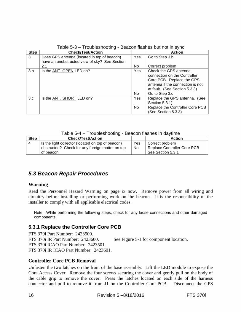
Table 5-3 – Troubleshooting - Beacon flashes but not in sync Step Check/Test/Action Action
3 Does GPS antenna (located in top of beacon) have an unobstructed view of sky? See Section 2.1
Yes No
Go to Step 3.b Correct problem
3.b Is the ANT. OPEN LED on? Yes No
Check the GPS antenna connection on the Controller Core PCB. Replace the GPS antenna if the connection is not at fault. (See Section 5.3.3) Go to Step 3.c
3.c Is the ANT. SHORT LED on? Yes No
Replace the GPS antenna. (See Section 5.3.1) Replace the Controller Core PCB (See Section 5.3.3)
Table 5-4 – Troubleshooting - Beacon flashes in daytime Step Check/Test/Action Action
4 Is the light collector (located on top of beacon) obstructed? Check for any foreign matter on top of beacon.
Yes No
Correct problem Replace Controller Core PCB See Section 5.3.1
5.3 Beacon Repair Procedures
Warning
Read the Personnel Hazard Warning on page ix now. Remove power from all wiring and
circuitry before installing or performing work on the beacon. It is the responsibility of the
installer to comply with all applicable electrical codes.
Note: While performing the following steps, check for any loose connections and other damaged components.
5.3.1 Replace the Controller Core PCB
FTS 370i Part Number: 2423500.
FTS 370i IR Part Number: 2423600. See Figure 5-1 for component location.
FTS 370i ICAO Part Number: 2423501.
FTS 370i IR ICAO Part Number: 2423601.
Controller Core PCB Removal
Unfasten the two latches on the front of the base assembly. Lift the LED module to expose the
Core Access Cover. Remove the four screws securing the cover and gently pull on the body of
the cable grip to remove the cover. Press the latches located on each side of the harness
connector and pull to remove it from J1 on the Controller Core PCB. Disconnect the GPS
FTS 370i Revision 5 –8/18/2016 17
antenna cable from the Controller Core PCB. Remove the four screws securing the Controller
Core PCB and pull the board to release it from the mother board.
Controller Core PCB Replacement
Carefully align the connectors on the back of the Controller Core PCB with the connectors on the
mother board. Gently push the board from the sides into the connections on the mother board.
Continue installation in the reverse order of the removal process. Apply power to the beacon and
verify that it operates correctly. If not, recheck all connections.
5.3.2 Replace the Power Supply
Part Number: 5150501. See Figure 5-2 for component location.
Power Supply Removal
Unfasten the two latches on the front of the base assembly. Lift the LED module to expose the
power supply. Remove the black, white and green wires from the input power connections to the
power supply. Remove the white/black and white/red wires from the output power connections
of the power supply. Remove the four screws that attach the power supply to the base.
Power Supply Reinstall
Place the power supply in the base observing the correct orientation of the terminal blocks and
secure with the four mounting screws. Attach the white/red wire to the output terminal labeled
“V+”. Attach the white/black wire to the output terminal labeled “V-“. Attach the green wire to
the terminal labeled “ ”. Attach the white wire to the terminal labeled “N”. Attach the black
wire to the terminal labeled “L”. Apply power to the beacon and verify that it operates correctly.
If not, recheck all connections.
5.3.3 Replace the GPS Antenna and Cable
Part Number: 6903294. See Figure 1-1 for component location.
GPS Antenna Removal
Unfasten the two latches on the front of the base assembly. Lift the LED module to expose the
Core Access Cover. Remove the four screws securing the cover and gently pull on the body of
the cable grip to remove the cover. Disconnect the GPS antenna cable from the Controller Core
PCB. Locate the GPS antenna on top of the beacon. Unscrew the GPS antenna from the light
collector. Pull up gently on the antenna to expose the antenna cable and connector.
GPS Antenna Reinstall
Install the black seal on the base of the replacement antenna and attach the antenna cable. Guide
the antenna cable back into the beacon through the light collector. Screw the antenna into the
light collector until the seal is firmly against the light collector. Continue installation in the
reverse order of the removal process. Apply power to the beacon and verify that it operates
correctly. If not, recheck all connections.
18 Revision 5 –8/18/2016 FTS 370i
5.3.4 Replace the Surge Suppressors
Part Number: 11000010290. See Figure 5-2 for component location.
Surge Suppressor Assembly Removal
Unfasten the two latches on the front of the base assembly. Lift the LED module to expose the
surge suppressors. Disconnect the wires at the L/N and the Ground positions. Insert a flat blade
screwdriver into the slot below the Ground position and push the handle toward the terminal
block to release the surge suppressor assembly.
Note: To replace only the surge suppressor, pull up on the surge suppressor module to remove it from the holder.
Surge Suppressor Reinstall
Position the L/N end of the surge suppressor over the DIN rail first. Insert a flat blade
screwdriver into the slot below the Ground position and push the handle toward the terminal
block. Push down on the surge suppressor assembly and remove the screwdriver. Verify that the
surge suppressor is firmly attached to the DIN rail. Reconnect the wires to the surge suppressor.
Lower the LED module to the closed position and secure both latches on the base assembly.
Apply power to the beacon and verify that it operates correctly. If not, recheck all connections.
5.3.5 Replace the LED Engine Assembly
FTS 370i Part Number: 1370180.
FTS 370i IR Part Number: 1370175. See Figure 1-1 for component location.
FTS 370i ICAO Part Number: 1370280.
FTS 370i IR ICAO Part Number: 1370275.
LED Engine Assembly Removal
Unfasten the two latches on the front of the base assembly. Lift the LED module to expose the
Core Access Cover. Remove the four screws securing the cover and gently pull on the body of
the cable grip to remove the cover. Press the latches located on each side of the harness
connector and pull to remove it from J1 on the Controller Core PCB. Remove the green ground
wire attached to the LED engine assembly. While securely grasping the LED engine assembly
with one hand, locate the ring on the hinge pin and pull to remove the pin. Lift the LED engine
assembly to remove it from the hinge.
LED Engine Assembly Replacement
Insert the LED engine assembly hinge into the base hinge and reinstall the hinge pin. Continue
installation in the reverse order of the removal process. Apply power to the beacon and verify
that it operates correctly. If not, recheck all connections.
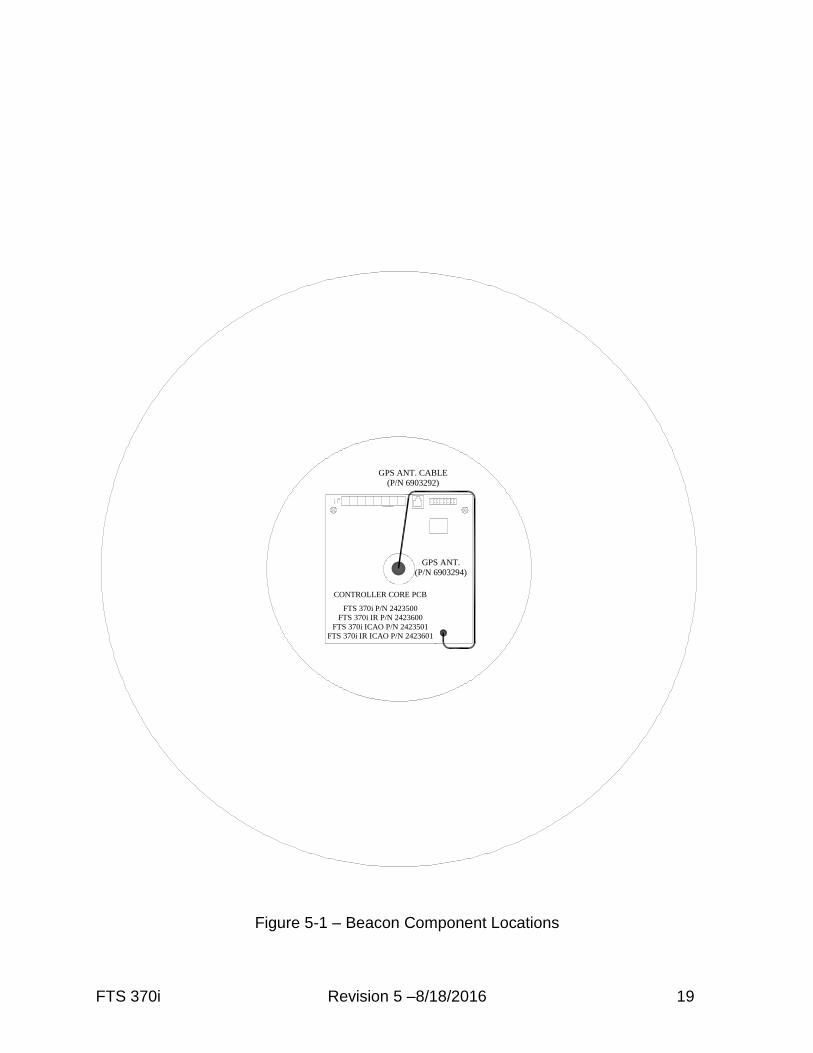
FTS 370i Revision 5 –8/18/2016 19
Figure 5-1 – Beacon Component Locations
CONTROLLERCORE PCB
(FTS 370i P/N 2423500)
(FTS 370i IR P/N 2423600)
GPS ANT.
(P/N 6903294)
GPS ANT. CABLE
(P/N 6903292)
CONTROLLER CORE PCB
FTS 370i P/N 2423500
FTS 370i IR P/N 2423600
FTS 370i ICAO P/N 2423501
FTS 370i IR ICAO P/N 2423601
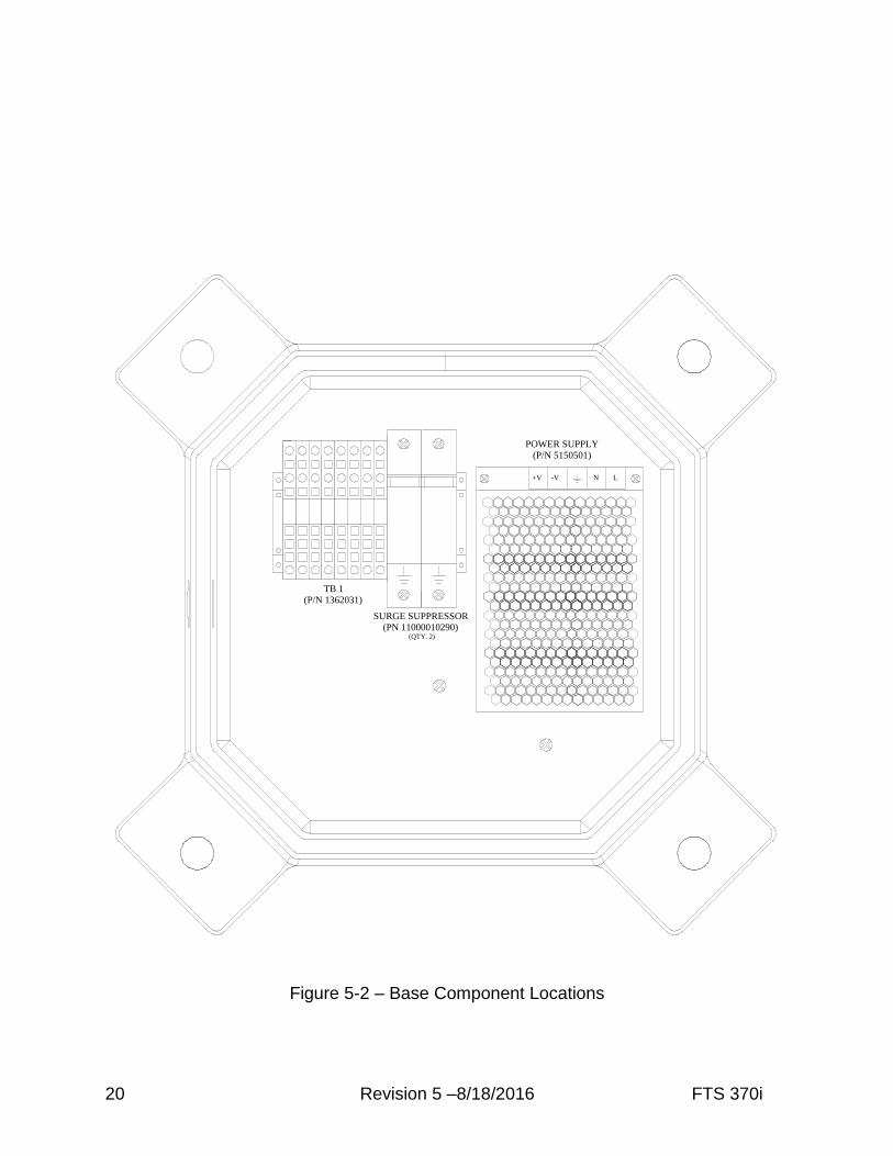
20 Revision 5 –8/18/2016 FTS 370i
Figure 5-2 – Base Component Locations
TB 1
(P/N 1362031)
+V -V N L
POWER SUPPLY
(P/N 5150501)
SURGE SUPPRESSOR
(PN 11000010290)(QTY. 2)
FTS 370i Revision 5 –8/18/2016 21
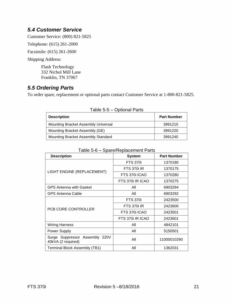
5.4 Customer Service
Customer Service: (800) 821-5825
Telephone: (615) 261-2000
Facsimile: (615) 261-2600
Shipping Address:
Flash Technology
332 Nichol Mill Lane
Franklin, TN 37067
5.5 Ordering Parts
To order spare, replacement or optional parts contact Customer Service at 1-800-821-5825.
Table 5-5 – Optional Parts
Description Part Number
Mounting Bracket Assembly Universal 3991210
Mounting Bracket Assembly (GE) 3991220
Mounting Bracket Assembly Standard 3991240
Table 5-6 – Spare/Replacement Parts
Description System Part Number
LIGHT ENGINE (REPLACEMENT)
FTS 370i 1370180
FTS 370i IR 1370175
FTS 370i ICAO 1370280
FTS 370i IR ICAO 1370275
GPS Antenna with Gasket All 6903294
GPS Antenna Cable All 6903292
PCB CORE CONTROLLER
FTS 370i 2423500
FTS 370i IR 2423600
FTS 370i ICAO 2423501
FTS 370i IR ICAO 2423601
Wiring Harness All 4842101
Power Supply All 5150501
Surge Suppressor Assembly 220V 40kVA (2 required)
All 11000010290
Terminal Block Assembly (TB1) All 1362031

RMA Policy Revision 2014B
Return Material Authorization (RMA) Policy IF A PRODUCT PURCHASED FROM FLASH TECHNOLOGY MUST BE RETURNED FOR ANY REASON (SUBJECT TO THE WARRANTY POLICY), PLEASE FOLLOW THE PROCEDURE BELOW: Note: An RMA number must be requested from Flash Technology prior to shipment of any product. No returned product will be processed without an RMA number. This number will be the only reference necessary for returning and obtaining information on the product’s progress. Failure to follow the below procedure may result in additional charges and delays. Avoid unnecessary screening and evaluation by contacting Technical Support prior to returning material. 1. To initiate an RMA: Call Flash Technology’s National Operations Center (NOC) at (800-821-
5825) to receive technical assistance and a Service Notification number. The following
information is required before a Service Notification number can be generated:
• Site Name/Number / FCC Registration number/ Call Letters or Airport Designator
• Site Owner (provide all that apply – owner, agent or subcontractor)
• Contractor Name
• Contractor Company
• Point of Contact Information: Name, Phone Number, Email Address, Fax Number and Cell Phone
(or alternate phone number)
• Product’s Serial Number
• Product’s Model Number or part number
• Service Notification Number (if previously given)
• Reason for call, with a full description of the reported issue
2. The Service Notification number will then serve as a precursor to receiving an RMA number if
it is determined that the product or equipment should be returned. To expedite the RMA
process please provide:
• Return shipping method • Shipping Address • Bill to Address • Any additional information to assist in resolving the issue or problem
3. Product within the Warranty Time Period
a. If to be returned for repair;
• RMA # is generated
• Once product is received and diagnosed;
• Covered under warranty – product is repaired or replaced
• Not covered under warranty – quote is sent to the customer for a bench fee of
$350 plus parts for repair
• If the customer does not want the product repaired, a $50 test fee is
charged before being returned
b. If advance replacement;
• Purchase order may be required before the advance replacement order is created
• RMA # is generated and the advance replacement order is created
• Once product is received and diagnosed;
• Covered under warranty – credit given back if PO received
• Not covered under warranty – credit will not be applied to PO
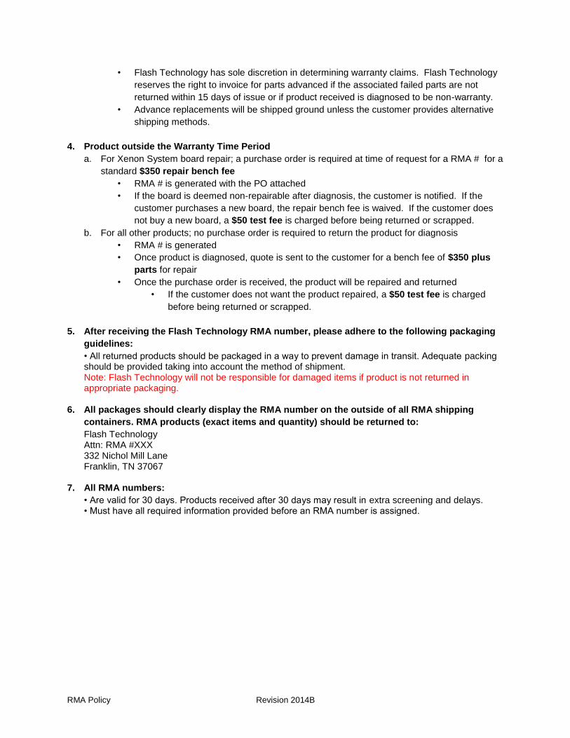
RMA Policy Revision 2014B
• Flash Technology has sole discretion in determining warranty claims. Flash Technology
reserves the right to invoice for parts advanced if the associated failed parts are not
returned within 15 days of issue or if product received is diagnosed to be non-warranty.
• Advance replacements will be shipped ground unless the customer provides alternative
shipping methods.
4. Product outside the Warranty Time Period
a. For Xenon System board repair; a purchase order is required at time of request for a RMA # for a
standard $350 repair bench fee
• RMA # is generated with the PO attached
• If the board is deemed non-repairable after diagnosis, the customer is notified. If the
customer purchases a new board, the repair bench fee is waived. If the customer does
not buy a new board, a $50 test fee is charged before being returned or scrapped.
b. For all other products; no purchase order is required to return the product for diagnosis
• RMA # is generated
• Once product is diagnosed, quote is sent to the customer for a bench fee of $350 plus
parts for repair
• Once the purchase order is received, the product will be repaired and returned
• If the customer does not want the product repaired, a $50 test fee is charged
before being returned or scrapped.
5. After receiving the Flash Technology RMA number, please adhere to the following packaging
guidelines:
• All returned products should be packaged in a way to prevent damage in transit. Adequate packing should be provided taking into account the method of shipment. Note: Flash Technology will not be responsible for damaged items if product is not returned in appropriate packaging.
6. All packages should clearly display the RMA number on the outside of all RMA shipping
containers. RMA products (exact items and quantity) should be returned to:
Flash Technology Attn: RMA #XXX 332 Nichol Mill Lane Franklin, TN 37067
7. All RMA numbers:
• Are valid for 30 days. Products received after 30 days may result in extra screening and delays. • Must have all required information provided before an RMA number is assigned.