chapter 11 equivalent systems, distributed loads, …krousgri/me270/wp-content/...11-4 chapter 11:...
TRANSCRIPT

Chapter 11: Equivalent Systems, Distributed Loads, Centers of Mass, and Centroids 11-1
Chapter 11
Equivalent Systems, DistributedLoads, Centers of Mass, andCentroids
“To be truly ignorant, be content with your own knowledge.”∼ Chuang Tzu (c. 360 BC - c. 275 BC)
11.1 Overview
Thus far we have covered a wide range of topics, but they all have one common theme inthe sense that you are learning to apply physics and mathematics to more and more realisticproblems in mechanics. We began this course with some preliminary vector concepts andmoved quickly into the particle equilibrium. After solving some interesting, but relativelysimple problems, we extended our capabilities by studying moments and distributed loads.That allowed us to consider the equilibrium of rigid bodies and solve a much wider rangeof problems. We applied the concepts of particle and rigid body equilibrium to analyzestructures including trusses, frames, and machines. Then friction, where we were able toincorporate slipping/tipping, wedges, and belts. Now we will consider equivalent systems,distributed loads, centers of mass and centroids. A proper understanding of these conceptswill make it possible for the student to apply their knowledge of statics and structures tocomplicated shapes that are subjected to complicated loadings. After completing this partof the course, the student should be able to,
1. Replace one set of forces and moments with an equivalent single force and single mo-
11-2 Chapter 11: Equivalent Systems, Distributed Loads, Centers of Mass, and Centroids
ment.
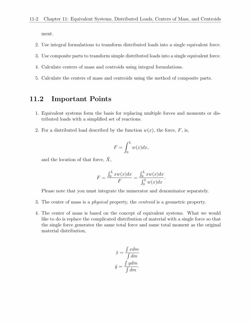
2. Use integral formulations to transform distributed loads into a single equivalent force.
3. Use composite parts to transform simple distributed loads into a single equivalent force.
4. Calculate centers of mass and centroids using integral formulations.
5. Calculate the centers of mass and centroids using the method of composite parts.
11.2 Important Points
1. Equivalent systems form the basis for replacing multiple forces and moments or dis-tributed loads with a simplified set of reactions.
2. For a distributed load described by the function w(x), the force, F , is,
F =
∫ L
0
w(x)dx,
and the location of that force, X,
F =
∫ L0xw(x)dx
F=
∫ L0xw(x)dx∫ L
0w(x)dx
.
Please note that you must integrate the numerator and denominator separately.
3. The center of mass is a physical property, the centroid is a geometric property.
4. The center of mass is based on the concept of equivalent systems. What we wouldlike to do is replace the complicated distribution of material with a single force so thatthe single force generates the same total force and same total moment as the originalmaterial distribution,
x =
∫xdm∫dm
y =
∫ydm∫dm
.

Chapter 11: Equivalent Systems, Distributed Loads, Centers of Mass, and Centroids 11-3
5. The centroid effectively defines the geometric center of an object,
x =
∫xdA∫dA
y =
∫ydA∫dA
.
6. When your object has constant thickness and uniform density, the center of mass andthe centroid occupy the same point. This equivalency can be exploited to break objectsdown into relatively simple pieces and make calculations much more straight forward.
11.3 Equivalent Systems
The concept of equivalent systems is a very powerful one in mechanics. Moreover, introducingit here should pose few difficulties for students because expertise in working with vectors andcalculating moments has already been established. The concept is quite simple. We considerone set of forces and moments and replace them with a second set of forces and momentsthat has the same net effect. The only real difficulty is distinguishing between equivalentsystems and equilibrium. It is a subtle distinction, but for equivalent systems, we just wantto simplify a system of forces and moments. We may not consider all the reactions acting onthe object and the net effect is often different from zero. For equilibrium, we must considerall the forces and moments and they must add up to zero.
In truth, we have already touched on this concept back when we discussed force couples.There we replaced two equal and opposite forces offset by some distance, d with a singleconcentrated moment. One thing to keep in mind is that you must draw a separate diagramfor each system. That is very important because trying to put both systems on the samediagram can only lead to confusion and catastrophe.
Let’s begin with an illustration of equivalent systems.

11-4 Chapter 11: Equivalent Systems, Distributed Loads, Centers of Mass, and Centroids
Example Consider the example below. If System I consists of four forces and a con-centrated moment1 and System II consists of a force located at point B and a differentconcentrated moment. If the force in System II has a magnitude of 300 lbs. and the con-centrated moment has a magnitude of 600 ft.*lbs., determine the magnitudes of F1, F2, andF3.
For system I we have,
∑Fx = F − F1 = 200lbs.− F1∑Fy = F3 − F2∑
M/B = (2ft.)F1 + (4ft.)F3 + (2ft.)F2 −M = (2ft.)F1 + (4ft.)F3 − 500ft.lbs.
For system II we have,
1Recall that a concentrated moment is really a force couple.

Chapter 11: Equivalent Systems, Distributed Loads, Centers of Mass, and Centroids 11-5
∑Fx = Rcos(53.13o)∑Fy = Rsin(53.13o)∑
M/B = 600ft.lbs.
In order to make the two systems equivalent, the forces in the x and y direction must bethe same2 and the net moments must be the same. This leads us to,
∑F1 = 20lbs.∑F3 = 265lbs.∑F2 = 25lbs.
2N.B. the system may or may not be in equilibrium

11-6 Chapter 11: Equivalent Systems, Distributed Loads, Centers of Mass, and Centroids
Example Here is a cantilevered beam with a system of forces and moments on it. Whatforce and moment must act at point A in order to produce an equivalent system of forces(not including the reactions)? What about points B, C, and D?
The beam has a length, L = 3.5m, a = 0.25m, b = 0.75m, c = 1.5m, and d = 0.5m. Thevalue of F1 = 100N, F2 = 200N, F3 = 300N.
c
a d
F
F
O
A
B
a
1
1
C
F2
F3
x
y
b
D

Chapter 11: Equivalent Systems, Distributed Loads, Centers of Mass, and Centroids 11-7
Example Here is our wind turbine again. Replace the wind forces on the blades with anequivalent force and concentrated moment at the origin (the center of the actual turbine).We may assume that the thrust force on each blade (F1) is approximately 35 N (in the −xdirection). The lift force (F2) causing each blade to rotate is approximately 200N. You mayassume that the forces act at the center of each 20 m blade. These forces are all in the y− zplane. In addition, d1 = 65 m, d2 = 5 m.
FD
x
y
z
FL
FDFD
FL
FL
2d
1d

11-8 Chapter 11: Equivalent Systems, Distributed Loads, Centers of Mass, and Centroids
11.4 Distributed Loads
Wind and water loads, cars on a bridge, and people on a crowded walkway often generateloads that are approximated as a pressure (force per unit area) or a distributed load (forceper unit length). In order to utilize our equilibrium equations, however, we need forces andmoments. Consequently, it is often necessary to replace a pressure or distributed load witha single force. First, consider a simple example. We will apply a uniform load to a beamthat is 3 m long and the space, a between the wall and the beginning of the applied load is0.5 m. It should be easy to see that, if we want to replace this with a single force, it mustbe a 250 N load placed in the middle of the loaded region (i.e. X = 1.75 m).
F
X
a
L
100 N/m
Chapter 11: Equivalent Systems, Distributed Loads, Centers of Mass, and Centroids 11-9
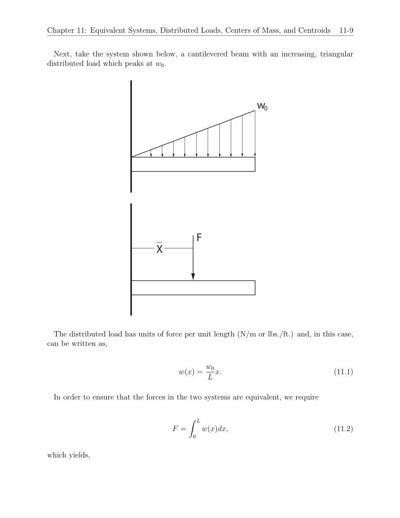
Next, take the system shown below, a cantilevered beam with an increasing, triangulardistributed load which peaks at w0.
F
X
w0
The distributed load has units of force per unit length (N/m or lbs./ft.) and, in this case,can be written as,
w(x) =w0
Lx. (11.1)
In order to ensure that the forces in the two systems are equivalent, we require
F =
∫ L
0
w(x)dx, (11.2)
which yields,
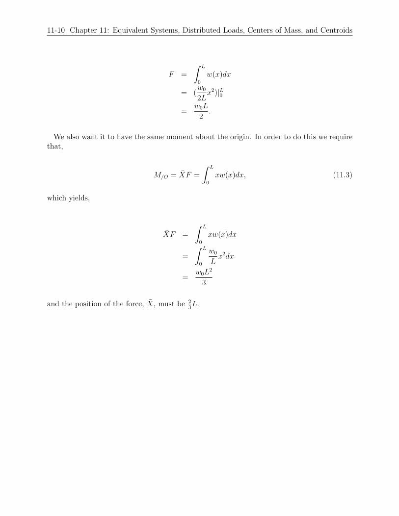
11-10 Chapter 11: Equivalent Systems, Distributed Loads, Centers of Mass, and Centroids
F =
∫ L
0
w(x)dx
= (w0
2Lx2)|L0
=w0L
2.
We also want it to have the same moment about the origin. In order to do this we requirethat,
M/O = XF =
∫ L
0
xw(x)dx, (11.3)
which yields,
XF =
∫ L
0
xw(x)dx
=
∫ L
0
w0
Lx2dx
=w0L
2
3
and the position of the force, X, must be 23L.

Chapter 11: Equivalent Systems, Distributed Loads, Centers of Mass, and Centroids 11-11
Example Here is another distributed load acting on a beam. Replace the distributed loadwith a single force.
w(x)=A(x +1) kN/m2
x
y
L = 2 m

11-12 Chapter 11: Equivalent Systems, Distributed Loads, Centers of Mass, and Centroids
11.5 Centers of Mass and Centroids
Right up front we should note that the center of mass is a physical property while the centroidis a geometric property.Having said that, the concepts of center of mass and centroid arebased on the notion of equivalent loads. The center of mass provides the location of thesingle gravitational force that we usually use in our equilibrium equations and is defined by,
x =
∫xdm∫dm
y =
∫ydm∫dm
z =
∫zdm∫dm
.
The differential element dm is usually broken down in the following way, dm = ρdv.Consequently, if the object has a uniform density, these equations simplify,
x =
∫xdv∫dv
y =
∫ydv∫dv
z =
∫zdv∫dv
,
which effectively defines the centroid of the volume in x, y, and z coordinates. We shouldnote that the tilde is used to denote the coordinates of the center of mass while the overbar is used for the coordinates of the centroid. For two dimensional problems (constantthickness) it suffices to specify the x and y coordinates,
x =
∫xdA∫dA
y =
∫ydA∫dA
.
Chapter 11: Equivalent Systems, Distributed Loads, Centers of Mass, and Centroids 11-13
Depending on the geometry some integrals may be especially difficult to evaluate analyti-cally. In that case, we can use numerical methods to estimate the integrals or simplify thegeometry and approximate it with simple shapes. This technique is very useful to engineersand is referred to as the the method of composite parts. Probably the best way to proceedis to do a few examples.
11-14 Chapter 11: Equivalent Systems, Distributed Loads, Centers of Mass, and Centroids
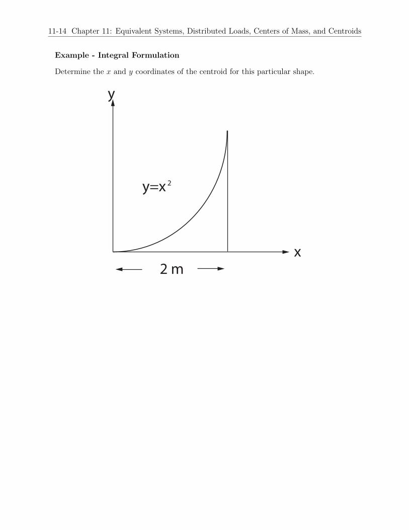
Example - Integral Formulation
Determine the x and y coordinates of the centroid for this particular shape.
y=x 2
x
y
2 m

Chapter 11: Equivalent Systems, Distributed Loads, Centers of Mass, and Centroids 11-15
Example - Integral Formulation Calculate the centroid and center of mass of thisparticular structure. You may assume that the density, ρ varies as 2000kg/m3 +100kg/m4y.
y=(x +1)2
x
y
2 m

11-16 Chapter 11: Equivalent Systems, Distributed Loads, Centers of Mass, and Centroids
Example - Integral Formulation One more centroid calculation. In this case, the xcoordinate should be obvious, but the y coordinate is a little more challenging.
y=x 2
x
y
2 m 2 m

Chapter 11: Equivalent Systems, Distributed Loads, Centers of Mass, and Centroids 11-17
Example - Composite Parts
x
y
2 m
1 m
5 m

11-18 Chapter 11: Equivalent Systems, Distributed Loads, Centers of Mass, and Centroids
Example - Composite Parts
Use composite parts to find the centroid (and coincidentally the center of mass) of thishomogeneous steel plate (with uniform thickness).
Chapter 11: Equivalent Systems, Distributed Loads, Centers of Mass, and Centroids 11-19
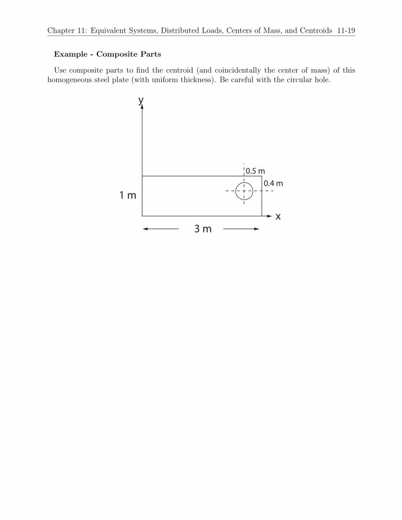
Example - Composite Parts
Use composite parts to find the centroid (and coincidentally the center of mass) of thishomogeneous steel plate (with uniform thickness). Be careful with the circular hole.
x
y
3 m
1 m
0.5 m
0.4 m

11-20 Chapter 11: Equivalent Systems, Distributed Loads, Centers of Mass, and Centroids
Chapter 12: Fluid Statics 12-1
Chapter 12
Fluid Statics
“Eureka!”
∼ Archimedes, after his discovery of buoyancy1.
12.1 Overview
In fluid mechanics we usually worry about moving fluids, especially flows through pipes,around airfoils, and fluid jets. One application of moving fluids that fits into our discussionof statics is air drag which was very important to the survival of Mr. Sulu and Mr. Kirk inan earlier chapter. Here we will consider what happens in fluids that are not moving.
Beginning with buoyancy, we will investigate the freedom ship, submarines, and offshoreoil rigs. After that, the effects of fluid pressure on dams, gates, and submerged structureswill be explored as well as wind loads on frames and machines. As you may have guessedthe problems will continue to get more realistic.
At the end of this chapter, the student will be able to,
1There are many interesting aspects to this story. The first is that the Greeks had such a single, short wordto express the idea, “I have made a leap in understanding,” suggesting that they were accustomed to suchthings. The other is that, after having figured out that the density of an objected could be determined bycomparing its weight to the amount of water it displaced, Archimedes was so overjoyed that he failed to graba towel and ran from the public bath back to his home, naked. Lastly, many people remember Archimedesonly for his role in elucidating buoyancy, but his contributions extended to other areas of mechanics (thediscovery of the principle of the lever, design of a screw pump) and mathematics (the “method of exhaustion”to compute infinite series and the approximation of π).

12-2 Chapter 12: Fluid Statics
1. Apply the concept of buoyancy to model the forces acting on submerged or partiallysubmerged structures.
2. Model distributed loads caused by pressure and quantify the forces (and their location)that act on submerged structures.
12.2 Buoyancy
Everyone knows the story of Archimedes and whatever you think of celebrating your discov-eries by running naked down the street, it represented a tremendous leap in understanding.In simple terms, his discovery led us o the definition for the buoyancy force acting on asubmerged or partially submerged object,
Fb = ρfluidgV, (12.1)
where Fb is the buoyancy force, ρfluid is the density of the fluid in which the object issubmerged, and V is the volume of fluid displaced2. Essentially, the buoyancy force is equalto the weight of the fluid displaced by your object. Keep in mind that an object may notalways be completely submerged. In that case, only the submerged portion contributes tothe buoyancy force.
2Some useful numbers to remember: The density of air is approximately 1.28kg/m3, the density of wateris approximately 1, 000kg/m3, and ρg = 62.4lbs./ft3

Chapter 12: Fluid Statics 12-3
Example: The Freedom ShipFor an example, we will use the Freedom Ship which, once completed, will be the largestship in history and will support an entire floating city. It will continuously circle the globe,visiting most of the earths inhabited coastal regions every two years. The Freedom Ship willbe approximately one mile long, 750 ft. wide, and 25 stories high ( 340 ft.) and its top-mostdeck will function as an airfield for small passenger aircraft. Perhaps the most impressivestatistic is the proposed weight of the ship, approximately 2.7 million tons. It will be ableto house between 50,000 and 200,000 passengers with a crew of 15,000. Our goal today is tofigure out how deep this boat is going to sit in the water. A very simple analysis you mightsay. But a good starting point. The most difficult aspect is the actual construction. It islikely that completely new manufacturing techniques will have to be developed before theship ever leaves port.
Figure 12.1: An aerial view of the proposed Freedom Ship

12-4 Chapter 12: Fluid Statics
Example: The Hindenburg DisasterThe Hindenburg (technically the LZ 129 Hindenburg) was a German-made dirigible (some-times called an airship) that was famously destroyed on May 6, 1937. As it was engulfed inflame, Herbert Morrison’s famous narration of the disaster accentuated the feeling of help-lessness and tragedy felt by those on the ground. There were 97 people on board the giantship (36 passengers and 61 crew members) and, given the magnitude and swiftness of thefire, it is remarkable that only 35 of them died (13 passengers and 22 crew members) inaddition to 1 person on the ground.
This disaster was a key moment in engineering history because it was one of the firstreally well publicized disasters and it shook the public’s faith in these types of airships. Tosome extent, it also damaged the reputation of engineers in general. While it is unlikelythat airships would have been able to compete with passenger planes in the long term, theHindenburg disaster dramatically decreased their utility.

Chapter 12: Fluid Statics 12-5
Figure 12.2: Transcript of Herbert Morrison’s commentary: It’s practically standing stillnow they’ve dropped ropes out of the nose of the ship; and (uh) they’ve been taken ahold ofdown on the field by a number of men. It’s starting to rain again; it’s... the rain had (uh)slacked up a little bit. The back motors of the ship are just holding it (uh) just enough tokeep it from...It’s burst into flames! It’s burst into flames and it’s falling it’s crashing! Watchit; watch it! Get out of the way; Get out of the way! Get this, Charlie; get this, Charlie!It’s fire... and it’s crashing! It’s crashing terrible! Oh, my! Get out of the way, please! It’sburning and bursting into flames and the... and it’s falling on the mooring mast. And allthe folks agree that this is terrible; this is the one of the worst catastrophes in the world.[indecipherable] its flames... Crashing, oh! Four- or five-hundred feet into the sky and it...it’s a terrific crash, ladies and gentlemen. It’s smoke, and it’s in flames now; and the frameis crashing to the ground, not quite to the mooring mast. Oh, the humanity! And all thepassengers screaming around here. I told you; it - I can’t even talk to people, their friendsare out there! Ah! It’s... it... it’s a... ah! I... I can’t talk, ladies and gentlemen. Honest: it’sjust laying there, mass of smoking wreckage. Ah! And everybody can hardly breathe andtalk and the screaming. Lady, I... I... I’m sorry. Honest: I... I can hardly breathe. I... I’mgoing to step inside, where I cannot see it. Charlie, that’s terrible. Ah, ah... I can’t. Listen,folks; I... I’m gonna have to stop for a minute because [indecipherable] I’ve lost my voice.This is the worst thing I’ve ever witnessed.

12-6 Chapter 12: Fluid Statics
Here we will estimate how much water ballast was required to keep the Hindenburg at afixed height. First, treat the Hindenburg as a particle. The Hindenburg had a volume of200,000 m3, a weight of 130 tons (you will need to convert this number to metric units) anda maximum speed of 135 km/h. If the density of hydrogen is 0.089 kg/m3, that of air is 1.28kg/m3, and the density of water is 1,000 kg/m3, determine the volume of water required tomaintain equilibrium. What if you had used helium (0.18 kg/m3) instead of hydrogen?

Chapter 12: Fluid Statics 12-7
12.3 Fluid Statics and Distributed Loads
In fluids the pressure increases linearly with depth below the water’s surface. In fact, fluidpressure only depends on atmospheric pressure (which is often negligible) and the depthbelow the surface. To illustrate how this works, we will consider a Sea Wall of the type usedto protect cities (such as New Orleans) that lie below sea level. It’s very tricky to build thesetypes of structures because cities that lie below sea level tend to have soft soil. Consequently,they cannot support very large moments.
Water
Sea
Wall
H
y
x
Sea
Wall
y
z
w
dy
Figure 12.3: A simple sea wall with width, w, and a water depth, H.
Right now we are primarily concerned with the force that the water exerts on the Sea Walland its location. Since the pressure, p, can be written,
p = ρgy,
(provided that we put the origin at the surface of the water and measure y positive downward,and neglect atmospheric pressure), we can integrate the pressure over the area to obtain thetotal force. First, we draw a differential area with width, w and height, dy. Since thepressure is constant across the width, we do not have to deal with differential areas in the zdirection. The total force on this differential area is,
dF = (ρgw)ydy,
and the total force is obtained by integrating over the surface (in this case by integratingthrough the depth),

12-8 Chapter 12: Fluid Statics
F =
∫ H
0
(ρgw)ydy = (ρgw)H2
2.
The next challenge is figuring out where the force is located. Keep in mind that we havealready derived the proper location for a force caused by a triangular load distribution. Inthis case, we have just rotated the problem 90o.

Chapter 12: Fluid Statics 12-9
Our next example involves Hoover Dam, one of the greatest monuments to industrialstrength and human audacity. The dam itself rises approximately 726 feet above the floorof the Black Canyon between Nevada and Arizona. It is 1,244 feet long, 660 feet thick at itsbase, 45 feet thick at its crest and weighs 5,500,000 tons. The lake it created, Lake Mead,backs up 110 miles behind the dam and is nearly 500 feet deep. It contains enough waterto submerge the state of Connecticut under 10 feet of water or to supply 5,000 gallons toevery person in the world. Perhaps even more impressively, the concrete dam was cast as asingle solid piece. Pouring started in June of 1933 and continued 24 hours a day, seven daysa week until May of 1935.
Figure 12.4: An aerial view of Hoover Dam
The engineer responsible for this feat was Frank Crowe.He studied civil engineering atthe University of Maine and, after a summer internship studying the drainage basin of theYellowstone River, joined the U.S. Governments Reclamation Service. Crowe was widelyconsidered the best construction engineer in the United States and was eventually hired bythe Six Companies to spearhead their efforts to obtain the Hoover Dam contract. He was thefirst to use cable ways to transport people and supplies to the worksite. In many instancesthe cables were required to support loads of several tons. In addition, because falling rockswere always a hazard during the construction of the dam, the first hard hats were developed

12-10 Chapter 12: Fluid Statics
by workers using baseball caps and tar as raw materials. It is worth noting that, afterpainstaking calculations and recalculations and four years of construction, nobody knew forsure that the dam would work. The only way to be certain was seal the diversion tunnelsand hope for the best.
Figure 12.5: Transporting equipment and materials at Hoover Dam
Model the dam as a simple cantilever that rises up out of the bottom of Black Canyon.Given the weight of the dam and the depth of the water behind it, calculate the reactionforces and moment at the base of the dam.
Chapter 12: Fluid Statics 12-11
One of the key aspects of this type of analysis is that the force that the water exerts on thedam increases with the depth squared and the moment increases with the depth cubed. Thatis crucial. Using these methods, will make it possible to analyze a wide array of relevantproblems from the failure of the Teton Dam in southeastern Idaho on June 5th, 1976 tothe failure of the levees in New Orleans after Hurricane Katrina. While these disasters areprobably the best known to American students, some of the biggest failures have occurred inChina and Hungary 3. The most dangerous dam in the world is in just upriver from Mosul,Iraq.
3The Banqiao Dam failed in 1975 killing approximately 26,000 people during the resulting flood andcausing nearly 145,000 more deaths as a result of disease. The Kolontar red mud dam failure did not killnearly as many people but contaminated huge tracts of land to the point that humans cannot return formany years.

12-12 Chapter 12: Fluid Statics
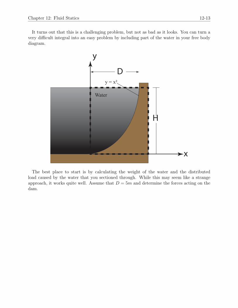
A parabolic bridge. One elegant trick that Civil Engineers use to improve the stability oftheir dams is to make them parabolic. This allows the weight of the water to press the daminto the ground making it harder to tip over and easier to create a seal between the bottomof the dam and the river bed. At first glance, this looks like a very challenging problembecause you know that the pressure always acts normal to the face of the dam.
y = x²
Water
x
y
D
H
Chapter 12: Fluid Statics 12-13
It turns out that this is a challenging problem, but not as bad as it looks. You can turn avery difficult integral into an easy problem by including part of the water in your free bodydiagram.
y = x²
Water
x
y
D
H
The best place to start is by calculating the weight of the water and the distributedload caused by the water that you sectioned through. While this may seem like a strangeapproach, it works quite well. Assume that D = 5m and determine the forces acting on thedam.

12-14 Chapter 12: Fluid Statics