structural damage caused by impulsive loads: a...
TRANSCRIPT

, ¢ . . . ~ , , . t 1 i - ' . ~ - : ~ - " . . . . .
M I N I S T R Y OF A V I A T I O N
R. & M. No. 3408
AERONAUTICAL RESEARCH COUNCIL
REPORTS AND MEMORANDA
Structural Damage Caused by Impulsive Loads: A Theoretical Analysis
By E. H. MANSFIELD, S c . D . , F . R . A e . 8 . , A . F . A . I . A . A .
LONDON: HER MAJESTY'S STATIONERY OFFICE
I965 PRICE I 4 $ . o d . NET

Structural Damage Caused by Impulsive Loads" A Theoretical Analysis
By E. H. MANSFIELD, S c . D . , F . R . A e . S . , A . F . A . ! . A . A .
COMMUNICATED BY THE DEPUTY CONTROLLER AIRCRAFT (RESEARCH AND DEVELOPMENT),
MINISTRY OF AVIATION
Reports and Memoranda No. 3408 *
April, z964
Summary. A general theoretical technique is presented for the estimation of structural damage caused by impulsive
loads. The technique, though approximate, takes account of differences that may exist between the elastic and plastic modes of deformation. A detailed analysis, with some numerical results, is presented for the case when the impulsive load is a uniformly distributed pressure whose magnitude varies time-wise as a rectangular
pulse.
Section
1.
2.
.
.
LIST OF CONTENTS
Introduction.
Simplified Elastic Behaviour of Structures
2.1 Equivalent mass-spring system for semi-rigid structure in elastic mode
2.2 Values of M, K, f and P for beams (elastic mode)
2.3 Values of M, K, f and P for plates (elastic mode)
Simplified Plastic Behaviour of Structures
3.1 Plastic behaviour of redundant structures
3.2 Plastic behaviour of practical structures
3.3 Determination of ~/~y for beams and plates
3.4 Equivalent mass-spring system for structure in plastic mode
3.5 Values of P, F e,/* and ~ for beams (plastic mode)
3.6 Values of P, F ~,/* and ~ for plates (plastic mode)
Dynamic Loading of Simplified Elasto-Plastic Structures
4.1
4.2
4.3
4.4
4.5
4.6
4.7
Non-dimensional time, force, impulse and damage terms
Analysis for t o > t ~ and P > F ~'
Analysis for t o > t 1 and ½-F ~ < P < F ~:
Analysis for t o < t *
Graphical presentation of the damage
Structural behaviour under sudden impulse
Influence of rate of loading on the yield stress
*' Replaces R.A.E. Report No. Structures 294--A.R.C. 26 156.

LIST OF CONTENTS--continued Section
5. Comparison with Two-Term Solution and with Previous Theory
6. Conclusions
Symbols
References
Additional Notation Used in the Appendices
Appendices I and II
Illustrations--Figs. 1 to 12
Detachable Abstract Cards
Appendix
I.
II.
LIST OF APPENDICES
Dynamics of the mode-to-mode change
Impulsive damage in simply supported beams: a two-term solution
Figure 1.
2, 3, 4
5.
6.
7.
8.
9.
10.
11.
12.
LIST OF ILLUSTRATIONS
Equivalent mass-spring system
Elasto-plastic relations considered in Section 3
Load vs. central deflexion for statically loaded beams
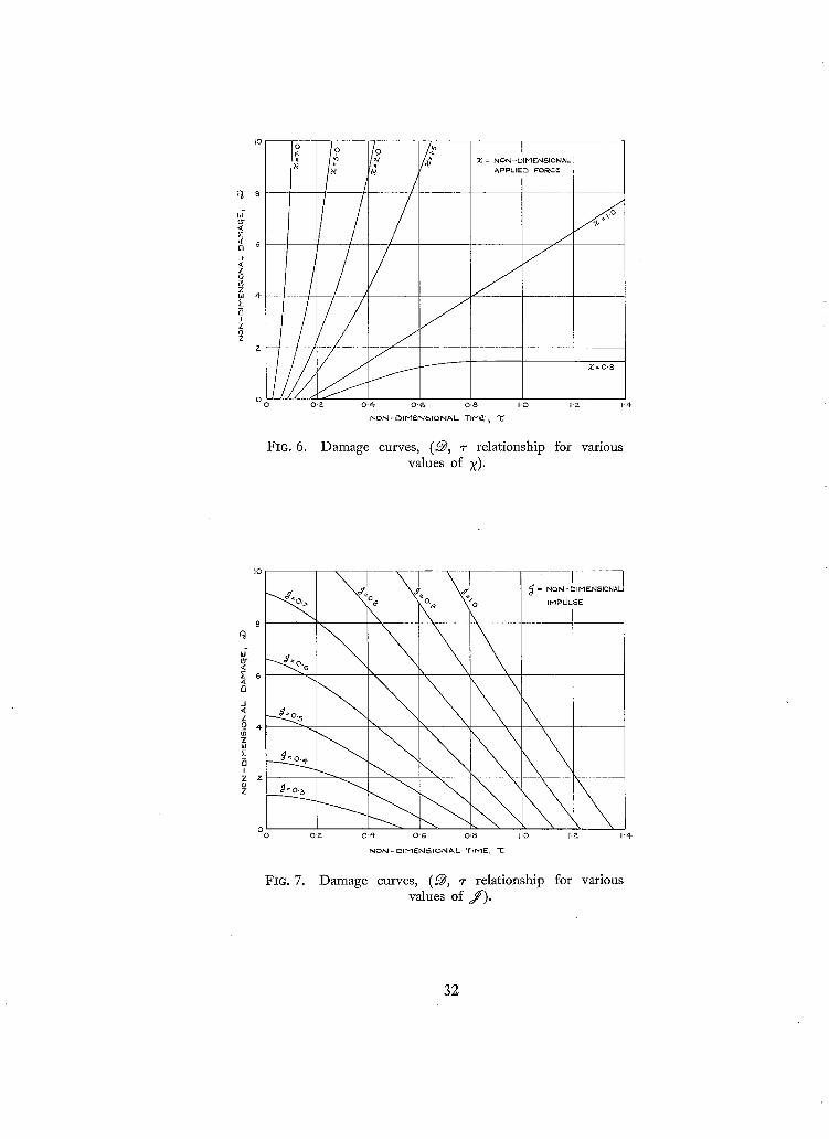
Damage curves (9, ~- relationship for various values of X)
Damage curves (~, ~- relationship for various values of J )
Damage curves (~/v¢ ~, ~- relationship for various values of X)
Non-linear force-displacement relationship
Linear work-hardening
Damage due to sudden impulse (~, j relationship for various values of ~)
Comparison of ~ , yo 2 relationships
1. Introduction.
The theoretical estimation of structural damage caused by impulsive loading, particularly blast pressure, has been considered by a number of authors, e.g. Fox 1, Christopherson~, Montgomery and Taub ~, Beer and Dahl 4, and Thornhill ~, 6. The pressure-time (p, t) variation most commonly assumed is of the form
P = po(1 - ct)e -a,
an empirical relation appropriate to conditions a moderate distance away from a spherical explosion: p is the pressure in excess over atmospheric pressure and c is a constant.
In the above investigations the target is a single mass attached to a spring and friction slide. Thornhill and Coombs 5, 6 have analysed such a system, particularly in the context of aircraft attack
2

by blast, and have shown that the relevant parameters may be chosen to describe adequately the results of numerous experiments. They also distinguish between 'localised damage' which is characterised by a short-time interval of loading, and 'lever-type damage' which describes the
damage mechanism in a wing which is subjected to a long-time interval of loading. In an actual structure, of course, infinitely many modes are generally excited, but analysis and experiment (in
the elastic regime) show 7,8 that a single mode tends to be dominant. Furthermore, the dominant
mode often closely resembles the static mode of deflexion under the given applied load distribution. This resemblance is particularly marked when the applied load distribution is not dissimilar to the
distribution of inertia loading. Now, we are concerned here with the estimation of damage to a structure, and accordingly the
plastic behaviour of the structure is no less important than the elastic behaviour. Of course, if the
plastic mode of deformation coincides with the elastic mode--differing only in magnitude--it is
possible to represent the structure precisely by a mass attached to a spring with appropriate inelastic characteristics. In general, however, the elastic and plastic modes differ and some account should be taken of these differences. Such account is taken here by assuming that the structure deforms under dynamic loading in precisely the same deflexion patterns that it would develop under static loads. Thus, initially the structure deforms in an elastic mode until the magnitude of this mode is such that yielding occurs; further deformation takes place in a plastic mode superposed on the maximum amplitude of the elastic mode. Such a scheme is not, of course, rigorously correct (except under certain 'soft' time-wise load variations), but it is the most realistic physical assumption that can be made which, at the same time, retains the simplicity inherent in a single-degree-of-freedom (albeit with a 'split mode') analysis. The novel feature of this paper is the adoption of such a 'split mode' analysis which provides a supplementary approach to earlier analysis and which has more direct application to structural-damage studies for isolated structural members.
The dynamic elasto-plastic behaviour of structures deforming in such a split mode is considered
here, with particular reference to beams and plates; the extension of the analysis to incorporate the split-mode feature is shown to be quite small. A detailed analysis is then presented for the case
when the impulsive load is a uniformly distributed pressure whose magnitude varies time-wise as
a rectangular pulse.
2. Simplified Elastic Behaviour of Structures. In solving dynamic load problems involving a structure with many degrees of freedom, Williams 7
has shown that it is often sufficient to restrict attention to a single, arbitrarily chosen mode. In such a case, the real structure is said to be replaced by a 'semi-rigid' structure, in which the shape of the deflexion pattern is fixed and only the amplitude of movement is variable. Furthermore, the overall behaviour of such a semi-rigid structure is not very sensitive to the precise form chosen for the mode. Thus, the period of vibration of a simply supported beam, constrained to deflect into the shape it would assume under a uniform load, is only 1.2% in excess of the true value. Similarly, if the beam is constrained to deflect into its true fundamental mode (a half sine wave) the strain energy stored by a uniformly distributed load is only0.15 % less than the true value. The closeness of these results is due to the fact that the uniformly distributed load acts in much the same way as the inertia loading or, in mathematical terms, the first term in the Fourier expansion of the uniform load is the dominant term. There are analogous results for plates, and for boundary conditions other
than simple support.
3
(91391) A 2

In the subsequent analysis, advantage is taken of the simplifications resuking from the assumption of a single degree of freedom. Furthermore, this concept is carried over into the plastic range, despite the fact that the elastic and plastic modes of deformation are, in general, different. We also adopt William's device in which the semi-rigid structure is replaced by an equivalent mass-spring system (see Fig. 1). This is done purely on grounds of convenience, and it involves no additional simplifications. The general method for deriving the equivalent mass and the equivalent spring constant is illustrated in Section 2.1. In Section 3 attention is given to the behaviour of structures in the plastic regime.
2.1. Equivalent Mass-Spring System for Semi-Rigid Structure in Elastic Mode
To illustrate the method for calculating the equivalent mass-spring system, we consider first a
beam whose assumed mode of deflexion, apart from a time-dependent factor of proportionality, is given by x(e) where e is the distance along the beam. We also define e = eo as our reference point, so that a knowledge of x(~o) completely determines the deflexion of the beam.
Now the kinetic energy of the beam is
1 m{~(e)}~d~ 2g 0
where m is the mass per unit length, and this must be equated to the kinetic energy of the equivalent mass M acting at the reference point e0:
Me {~(eo)} ~ •
The equivalent mass is therefore given by
M = o m [x~j0) . (1)
Similarly the strain energy in the beam is
EZ{x"(e)}~de 0
where a prime denotes differentiation with respect to ~. Equating this to the strain energy in the equivalent spring yields the following equation for the spring constant K:
K = f °E! [x"(e)/~ d~. o [X(eo)J (2)
It is to be noted that the natural frequency f of the equivalent mass-spring system is the same as that of the semi-rigid structure:
47r2f 2 = gK/M
; } g o EI{x"(e)}~ de
fo m{4e)? de (3)
The loading on the beam is represented by an equivalent load P which acts at the reference point and which does the same amount of work. Thus
P = f° I x( )t de. o p tX(~o))
(4)

The calculation of M and P for plates is straightforward; to calculate K, we require the expression
for the strain energy of a plate, and hence
K - {x(~0.%)}2 . D L\a~:~ + an~/ - 2 ( i - ~ ) ~a~:~ an ~ ~a~:an! . (5)
2.2. Values of M, K, f and P for Beams (Elastic Mode).
The following values are appropriate for a uniform beam subjected to a uniformly distributed
load per unit length. The reference point is taken at the centre.
If the beam is simply supported, we take
x(~) = sin rr~/a, say, (6)
where, for convenience, the (dimensional) constant of proportionality has been omitted. This yields
If the beam is clamped, we take
which yields
M = 0"5 ma, "~
K 48" 6 Et/a a ,
• f a 2
P 0" 637 pa.
(7)
~(~:) = ~:~(a- ~:)~, say, (8)
M = 0 " 4 0 6 m a ,
K = 205 EI/a 3,
f = a - ~ - ,
P = 0 . 5 3 3 p a .
(9)
2.3. Values of M, K, f and P for Plates (Elastic mode).
A rectangular plate with an aspect ratio greater than about 5 acts effectively as part of an infinite
strip, and it can therefore be treated as a 'beam'. The stiffening influence of the end supports in rectangular plates with more modest aspect ratios is not negligible, and the deflexion under uniform
pressure- -which we define as the elastic mode- -can be estimated, for example, by the method of
Kantorovich (see Refs.9, 10). However , in most cases such precision is not justified, and an accurate enough value can be obtained by a form of interpolation between the infinite strip and the square
plate considered below. The reference point (~0, %) is taken at the centre (½a, ½a).
2.3.1. Square plates.--If the sides of the square plate are simply supported, we take
x(~, ~7) = sin (rc~la) sin ( ,~da), (10) which yields
71//= O. 25 ma 2 ,
( = 0.25 pha°'),
K = 8.9 Eha/a 2, (11)
f = 0 . 9 5 ~ ,
P = 0 . 4 0 5 p a ~.

which yields
If the sides of the square plate are clamped, we take
7 ) =
M = O.165 ma 2,
( = 0" 165 pha~), K = 19" 6 Eha/a 2,
= 1 . 7 4 ~ ,
P = 0.285pa 2.
(12)
(13)
2.3.2. Rectangular plates.--In what follows it is assumed that the reference point is at the centre, and that b > a. For simply supported rectangular plates a crude interpolation, based on a composite mode in which equation (10) is valid at the ends and equation (6) valid over the central length of ( b - a), now yields the following values:
M = 0.25 ma(2b- a),
{ = 0.25 pha(2b- a)},
K = 4.45 Eh3(a + b)/a ~ ,
h [gE(b+a)tZ/2 (14) f = 0 . 6 7 ~ [ ~ ] ,
P = 0. 637 pa(b- O. 364a).
Similarly, for clamped rectangular plates, the adoption of a composite mode based on equations (12) and (8) yields the following values:
M = 0.406 ma(b-O.59a),
{ = 0.406 pha(b-O.59a)}, K = 18.8 EhS(b + O.04a)[a a,
h [gE(b + 0.04a) 11/2 (15) f = l ' 0 8 ~ ( p - ~ _ 0 . - - - - ~ a ) J '
P = 0"533pa(b-O.465a). j
3. Simplified Plastic Behaviour of Structures.
When part, or all, of a structure is stressed beyond the elastic limit the structure is said to be in the plastic regime. To assist in the understanding of the plastic behaviour of structures, it is helpful to consider first some simple structures whose material possesses idealised elasto-plastic characterstics.
A material whose stress-strain relationship is as shown in Fig. 2 is said to possess perfect plasticity, and a rod of such material would necessarily possess a load-displacement relationship which is similar to this. The same remarks would also apply to the bending moment-curvature relationship for an I-beam whose web does not contribute to the flexural rigidity. However, in a beam of rectangular section the spread of plasticity through the load-bearing material is gradual, and the bending moment-curvature relationship is as shown in Fig. 3. Fig 3 is also applicable to a plate in pure bending; but the loading on a plate is generally more complex, and the onset of the plastic regime then depends upon the magnitudes of the two principal moments. The critical combinations
6

of the principal stresses which suffice to initiate plasticity in a material are, strictly speaking, only determinable by experiment. However, although different materials behave in different ways, there is a corresponding choice of theories available which are in accord with experiment 11,1~. Further- more, for plates under normal pressure the predominating stress combination is such that the principal stresses are of the same sign, and it is in this region that the various theories, and experi- mental results, differ by only a few per cent. Thus the simplest of theories is sufficiently adequate and advantage is taken of this in Section 3.5 where the maximum principal stress criterion is adopted. Finally we may note that if the material stress-strain relationship is as shown in Fig. 4, which is not unlike that of mild steel, the corresponding bending moment-curvature relationship
for a plate or beam of rectangular section is as shown in Fig. 2.
3.1. Plastic Behaviour of Redundant Structures.
So far, the discussion has been centred on the basic plastic behaviour of a beam or plate in
bending. However, if the beam (or plate) forms part of a structure or is supported in such a way that it is 'redundant', the load-displacement relationship exhibits an additional complicating feature
associated with the spread of plasticity through the structure as a whole. This is most readily demonstrated by considering the uniformly loaded idealised I-beam whose bending moment- curvature relationship is as in Fig. 2..Both simply supported and clamped boundary conditions are considered, although it is only the latter condition which exhibits this additional feature. The ends of the beam are assumed to be free to move along the line of the beam so that membrane forces
cannot occur.
3.1.1. Ends simply supported.--In the elastic state the maximum (+ve) bending moment
occurs at the centre and is given by
d/d = pa~'/8.
Thus, when P = P:r, say
= 8Jg~/a ~ (16)
the bending moment at the centre attains its limiting value J///r ; a 'plastic hinge' develops there, and the beam can carry no further load because it is now acting as a mechanism. The central
deflexion is plotted against the load in Fig. 5.
3.1.2. Ends clamped.--In the elastic state the maximum ( - r e ) bending moment occurs
at the ends and is given by = pa~'/12.
Thus, when p = 12Jd~./a 2 (17)
the bending moments at the ends attain the limiting value ~/d F ; plastic hinges will develop there, but the beam does not yet fail because there are not sufficient hinges formed to convert the beam into a mechanism. Indeed, when equation (17) is satisfied, it can be shown that the ( + r e ) bending
moment at the centre is ½,//{g. Now when
p > 1 2 ~ / a ~

the slope of the load deflexion curve is the same as that for the simply supported case because there
is no change in the end moments. It follows from equation (17) and (16) that a central hinge will form, resulting in failure of the beam, when
p = p y
- !
= 16d~Y/a~" (18)
The complete load-deflexion curve is shown in Fig. 5 ; the three straight lines comprising this curve correspond to three distinct modes of deformation. The behaviour of a plate is more complex because there is, in general, a gradual mode change from the onset of plasticity to failure. Fortunately, the failure of a plate or beam can be estirnated without recourse to a detailed examination of the elasto-plastic behaviour. For example, if the position of the plastic hinges is known the principle of virtual work may be applied to determine the failing load. Thus for the clamped beam previously considered, the work done at failure by the applied load is ½paAx, where Ax is a virtual increase in the central deflexion, and this must be equated to the work done in the plastic hinges by the moment
//{~ acting over a total angular rotation of (2Ax/a+4Ax/a+2Ax/a), which leads directly to equation (18).
3.2. Plastic Behaviour of Practical Strzwtures.
We have already seen that in a redundant structure, such as a plate or clamped beam, there is a gradual transition from the elastic mode to the mode at failure, even when the material or the basic structural element possesses idealised elasto-plastic properties. Most practical materials exhibit no clearly defined yield point, and there is some work hardening in the plastic regime. These effects inevitably lead to further smoothing of this transition zone so that, for example, in the clamped
beam the actual relationship between the central deflexion and the applied load could be as shown
by the broken line in Fig. 5. Furthermore, all the curves of Fig. 5 refer to static loading conditions; under dynamic loading there will be an additional smoothing between the elastic and plastic modes due to the inertia of the structure resisting a sudden mode-to-mode change. The exact dynamic
analysis of even the simplest of structures presents formidable difficulties but, fortunately, the errors caused by ignoring the transition zone and neglecting work-hardening are of opposite sign
and are, roughly speaking, of comparable magnitude (see dotted lines in Fig. 5). This simplified approach is adopted here.
3.3. Determination of J ~ for Beams and Plates.
Let us assume that the material possesses idealised elasto-plastie characteristics with a yield stress ~ ,--which may be taken to be equal to the O. 2% proof stress of the actual material. When a beam of this material is subjected to its limiting bending moment d/i~ , the whole of the cross- section is assumed to be plastic, and the 'neutral axis' is determined from the condition of equilibrium of the direct stresses (+ err and - ay) acting over the cross-section: in other words, the neutral axis is at the centre of area. If z is measured from the neutral axis the moment ~ : is therefore given by
~:v j" [zldA (19) d @ A
where dA is an element of the cross-sectional area.

For an I-beam whose flange areas are A 1 and A~. (A 1 ~< A2), and the distance between flanges is
h, equation (19) reduces to
/di~ = hAle r .
Similarly for a plate of thickness h:
~ r = kh2¢r •
Alternatively, the limiting moment iN/. may be determined directly by experiment.
3.4. Equivalent Mass-Spring System for Structure in Plastic Mode.
The concept of the equivalent mass, etc., introduced in Section 2.1, may be conveniently carried over into the plastic mode. Thus, if the suffix p is introduced to indicate that the plastic mode is
under consideration, equations (1) and (4) for example, become simply
m f ~(~)~ M~ = o ~ o ~ t d~ (20)
F ~ ~ x~(f) ~ _
P~ : )0 p i ~ 0 ~ / ~
These values generally differ from M and P. Now the concept of the equivalent mass and the equivalent force has been introduced merely for
convenience, and the displacement of this equivalent mass--which is what matters--is unaffected by a proportional increase in Mp and P~). Thus either M~ or Pp may be scaled up (or down) to the appropriate value of M or P. In what follows M~) and P~ are scaled up by the factor (P/Pv), so that the 'equivalent force' in the plastic mode is the same as that in the elastic mode, P; the 'equivalent mass' in the plastic mode is now defined by
where M', say = /~M (21)
PM~ I~ - P ; M '
f x(~0) px(~) d~ m{~(~)} 2 d~ 0 0
f f° xp(~o ) px~,(~) d~ m{x(~:)} 2 d~ 0 0
The adoption of this scaling factor is not, of course, essential to the analysis, but it brings with it the advantage of continuity of P and F *~ at the mode-to-mode change.
3.4.1. Velocity change at mode-to-mode change.--It is shown in Appendix I that the velocity of the equivalent mass (M') immediately after the onset of the plastic mode is ~ times the velocity of the equivalent mass (M) immediately before the mode-to-mode change, where--to quote the formula appropriate to a plate--
to, ~o) 6 t ~(~, ~/,%(~, ~/d~ d~ = J J (22)

3.5. Values of P, F*, i~ and ¢ for Beams (Plastic Mode). If both ends of the beam are either simply supported or clamped, the mode at failure is given by
x~,(~) = 1 - 21 ~ l a l , (23) where, for convenience, ~ is now measured from the centre. Substitution of equation (23) into equation (20) gives
M~ = 0.333 ma,
P~ = 0.5 pa. ] (24)
Now the values of M and P, appropriate to the elastic mode, have already been determined and hence the factor /, is known. Also, the magnitude of the equivalent static force F "~ required for failure is given by equations (7), (16), or (9), (18).
Thus if the beam is simply supported we find
p
F ~
0.637pa, {(7) b i s}}
5 0 9 d d r / a !
0 848, "
1 22.
(25)
The corresponding values for the clamped beam are given by
P = 0.533 pa, {(9) bis} "~
F* 8 53 dZr/a,
/~ 0. 874,
1.10.
(26)
3.6. Values of P, F*, ff and d? for Plates (Plastic Mode).
A rectangular plate with an aspect ratio greater than about 5 acts effectively as part of an infinite strip, and it can therefore be treated as a 'beam'. The strengthening influence of the end supports in rectangular plates with more modest aspect ratios is not negligible, and there are methods avail- able for its estimation ls. However, in most cases such precision is not justified, and an accurate enough value can be obtained by a form of interpolation between the infinite strip and the square plate considered below.
3.6.1. they result in the following values. For simply supported boundaries:
P = 0.405 pa ~, {(11) bis} "~
F* 9.73 J @ ,
ff 0.811,
¢ = 1.22.
10
Square plates.--The failure modes of square plates are considered in Ref. 14, and
(27)

If the boundaries are clamped:
P = 0-285 pa 2, {(13) bis} "~
F * 12.2 ~//Zr,
/, 0. 863,
4, 1 . o o .
3.6.2.
(28)
Rectangular plates.--In what follows it is assumed that the reference point is at
the centre, and that b > a. The assumption of a composke mode--similar in character to those of
Section 2.3.2--yields the following results. For simply supported boundaries:
P = 0. 637 pa(b- O. 364a), {(14) bis} "~
F * = 5 - 0 9 ~ ( b ~ a ) ( b - 0 . 3 6 4 a ~ - - 0 . 3 ~ ] ' (29)
_ o.
/z = 0.848 _ 0-333a] '
4, = 1.22.
If the boundaries are clamped:
P = 0.533pa(b-O.465a), {(15) bis}
F* 8 " 5 3 ~ (b+O-'a667a) (b~-O'465a~ = - -
[b - 0.534a] [b - 0.465a] (30) /~ = O. 874 \ b - 0-. 5-~-a / lb, ~ 1 '
( ~ - 0-578a'~ 4, = 1. lO
4. Dynamic Loading of Simplified Elasto-Plastic Structures. In Section 2 it was shown that by restricting attention to a single mode the behaviour of a
structural component (e.g. an inter-rib panel) under impulsive pressure is readily analysed by reducing it first to an equivalent mass-spring system. Such a system, with the addition of a purely plastic component in the spring characteristic and with due allowance for the mode-to-mode change is now considered. We will determine the displacement x{= x(~0) } of a mass M subjected to a force P for a time t o , the mass being attached to an elasto-plastic spring such that the restoring force F is equal to Kx in the range 0 < x < x* and equal to Kx ~ ( = F ~) for x > x% When x reaches the value x ~ (corresponding to the mode-to-mode change) the mass M becomes/zM and its velocity
is altered by the factor 4,. Attention is given to the effects of non-linear elastic response and imperfect plasticity in Section
4.6.1.
4.1. Non-dimensional Time, Force, Impulse and Damage Terms. Before proceeding to the analysis of the elasto-plastic mass-spring system it is convenient to
introduce some non-dimensional terms which facilitate the presentation of results. The fundamental
11

f requency f of the structure is equal to that of the mass-spring system {see equation (3)} and it
provides a convenient means for non-dimensionalising the time interval t o by introducing
T ~ f t 0
2~r
Similarly the force P is conveniently expressed non-dimensionally 5 as a multiple of the yield force F e by writ ing
X = P~ F'~, (32)
while a non-dimensional measure of the impulse Pto is given by
J = w
_ P t o [g_K~'~ ( 3 3 )
2 ~ F ° \ ]VII "
The damage done to the structure may be equated to the amount of plastic deformation (i.e. per-
manent set) which the structure suffers 5, and it is convenient to express this non-dimensionally as
a multiple of the elastic deformation of the reference point prior to yielding:
= ( x ~ - x O ) / x ° , ( x ~ , : > x ° ) . (34)
It is to be noted that the numerical value of ~ depends upon the position chosen for the reference
point; note that if xln~x ~< x e the structure remains elastic and ~ is zero. It is also convenient to
be able to equate ranges of the numerical value of ~@ with such phrases as 'slight damage', 'severe
damage', etc. Obviously there is no universally valid scale, but to fix ideas we suggest the following average values for an aircraft or missile structure:
0 < ~ < ½ : slight damage
1 < ~ < 2 : moderate damage
2 < ~ < 8 : severe damage
> 8 : lethal damage
4.2. Analys is f o r t o > t ° and P > F °.
The equation of motion in the initial elastic phase is given by
MSO/g = P - K x , x < x* whose solution is
P x = ~7 (1 - cos 2rrft).
When x = x ° it is convenient to write t = t °, where, f rom equation (36)
1 t ° = 2 ~ f c o s - 1 (1 - Fo/p),
and in this section we assume that t o > t *¢ ,
12
(35)
(36)
(37)
(38)

so that the load is being applied when the structure starts to yield. Now at time t* the velocity
2" is given by
2* - 2~rfP sin 2~rfte K
and hence, from equations (22) and (37), the velocity immediately after time t* is given by
[2]~,=i% = 42"
= ¢ L K M
This provides one of the boundary conditions for the behaviour in the range
t* < t < to (40) when the equation of motion is
l~M£/g = P - F * , (valid for 2+ve) (41)
which may be integrated to give g ( P - F*) (t - t*) 2 (42)
x = x* + 42" ( t - t* ) + 2/~M
When t = t o the displacement and velocity, which will be identified by the symbols x o and So, are
therefore given by
Xo= x* + 4 2 * ( t o - t * ) + g ( P - F ; ) ~ d ° - t * ) ~
(43) g ( P - F*) (t o - t*) [
¢2* + I~M j ! S o
Now when t > t o the equation of motion is simply
t ,M~/g = - F * , (valid for 2 + re) (44)
and the maximum displacement, which occurs when 2 is zero, is accordingly given by
Xm~x = Xo + 2 ~ (2°)3" (45)
Expressed in non-dimensional terms equations (34), (37), (39), (43) and (45) reduce to
= M ~ ( x - ½) + ¢xA(2x - 1) 1/2 + x A ~ ( x - 1)/2~ ) where j (46)
A 2 ~ - cos-1 ( ~ ) •
4.3. Analysis for t o > t 1 and ½F e < P < F*.
If P < F* the analysis may require modification. This is because equations (41) and (42) are
valid only if 2 is + re, in other words up to such time t l , say, at which
• g(P- F*) (t~- t*) t 2 = 42" + 7 ~ - (47)
J = 0 ,
13

where ¢~e is given by equation (39). The time t 1 is accordingly given by
The corresponding value of x is Xm~ ~ and finally, in non-dimensional terms, we obtain
[ X - ½ ~ (49) = ~¢~ \ 1 - x]"
If t~ > t o > t '~ the analysis of Section 4.2 is valid. If P < ½F* the structure remains elastic and there is no damage.
4.4. A n a l y s i s f o r t o <<. t*.
Equation (36) which gives the displacement in the initial phase, is now only valid up to time t o ~ w h e l l
x0 = _g (1 - co s 2~fto),
( 5 0 )
2~rfP sin 2rcft o . x ° = K
In the range t o < t < t ° the equation of motion is
M 2 / g = - K x (51)
whose solution, which satisfies equation (50), is given by
P . = ~7 {cos 2 = f ( t - to) - cos 2~ft}. ( 5 2 )
The value of t * is determined by equating the above displacement to x ~', whence
1 ( t* = ~to + ~ sin-1 2P Z ~fto '
and the corresponding velocity ~e is accordingly given by
~ 2 , ¢ P {sin 2, , f t ~ sin 2 ~ f ( t * - to) } K
_ 2rrfP {4 sin2~rft0 - (Fe /P)~} ~12 (54) K
Finally, for t > t* the equation of motion is
i~M2/g = - F ~ , (valid for ~ + re)
and the maximum displacement, which occurs when ~ is zero, is accordingly given by
xm~ X = x ~ + 2 g F , ~ (55)
In non-dimensional terms the damage is given by
= / z # ( 2 x 2 sin2rrr - ½). (56)
14
(44 bis)

4.5. Graphical Presentation of the Damage.
Equations (46), (49) and (56), which express the damage in terms of the pressure and time interval, constitute one of the main features of the report. The results, for/x = $ = 1, are expressed in graphical form in Figs. 6, 7 and 8. In Fig. 6 ~ is plotted against ~- for various values of X. If X is large and ~- small it is difficult to determine ~ from Fig. 6, and accordingly Fig. 7 has been prepared in which ~ is plotted against ~- for various values of j ( = X~-). Finally in Fig. 8 2/o¢ r2 is plotted against ~- for various values of X, to facilitate the determination of ~ if 7 is large. If the parameters/z and $ differ significantly from unity, their influence on ~ must be determined from
the appropriate preceding equation; note that in equations (49) and (56) the damage varies with
/~ and ~ in proportion to/z~ ~.
4.6. Structural Behaviour under Sudden Impulse.
It is clear from Fig. 7 that the maximum damage caused by a given 'impulse' Xz occurs when
~ 0 , although for practical purposes the damage does not vary significantly over the range
0 < z < 0.2. In other words, if the time of application of the pressure is small in comparison with
the fundamental period of vibration, the resulting damage to the structure depends only on the
of pressure x time; more generally, the damage depends upon t- X d~ so that the case in product
which the pressure is not constant may also be readily analysed, for equation (56) may then be
cast in the form ~ /x~(2~-aJ ~ - ½) (57)
where
J = f x (58)
4.6.1. Non-linear structural behaviour.--It has just been shown that when 0 < + < 0.2 the loading acts effectively as a sudden impulse, which leads to considerable simplification in the analysis of the idealised elasto-plastic structure. Of greater importance, however, is the fact that the analysis can also be readily extended to the case of a structure with quite general characteristics. Thus we determine below the damage caused by a sudden impulse applied to a mass-spring system whose force-displacement curve is arbitrary, as shown in Fig. 9. The structure is assumed to be elastic up to the point A beyond which it deforms plastically with arbitrary work-hardening. To
simplify the discussion the influence of the parameters/x and ~ is ignored, and we will again define the damage by equation (34), although this definition is now not necessarily proportional to the actual permanent set. The initial elastic but non-linear curve OA might, for example, represent the
deflexion of a thin plate in which membrane forces play a significant role. After a sudden impulse I ( = Pto) the velocity of the mass is given by
~o = g I / M (59)
and accordingly the kinetic energy U is given by
U = g P / 2 M . (60)
Now when the velocity of the mass falls to zero, at x = Xmax, this kinetic energy is equal to the work done on the spring, so that
gI ~ = ~xm~ F dx (61) 2M 3 o
from which may be determined Xmax, and hence a measure of the damage.
15

Structure with linear work-hardening.
As an example in the application of equation (61) we determine below the damage caused by a sudden impulse to a structure exhibiting linear work-hardening as shown in Fig. 10. The spring characteristics are
F = K x , O < x <~ x* ] (62)
F = F* + ~ K ( x - x * ) , x >>. x*
where a, the ratio of the slopes of AB to OA, is a measure of the degree of work-hardening. Substitution of equation (62) into equation (61) now gives, in non-dimensional form
~@ = [(1 + ~(4~r~d 2 - 1)}1/°-- 1]/~. (63)
The variation of ~ with J and ~ is shown in Fig. 11. As might be expected the influence of work-
hardening is small for small values of ~ , but it can become of overriding importance for large values
of ~ . Similar conclusions may be drawn when the time of application of the pressure is not small in comparison with the fundamental period of vibration.
4.7. Influence of Rate of Loading on the Yield Stress.
It is shown in Refs. 15 to 18, for example, that the yield stress of a material is increased at extremely high rates of strain. In other words cry and hence F* and x* may depend on the variation
of ~ in the elastic range. The precise variation of ~ is probably of little consequence, and it is sufficient to consider the average value x*/t*.
Now t* is given by equations (37) and (53):
~ - ,
t* = ½t o + ~ s i n -1 2xsinTrft o '
and hence xe/t * may be determined.
to > t'~ ' 1
t o < t*, (64)
I t is to be noted that an extremely high rate of loading (i.e. very small to) does not imply an extremely
high rate of strain (i.e. very small t*). This is because the inertia of the structure intervenes, and the rate of strain in then primarily determined by the fundamental frequency of the structure. This point is made clearer by combining the second of equation (64) with equation (56), which gives
t* = ½t 0 + 1 tan -1 ( I~¢2"~I °~ (65) 27rf \ 2 ~ ] "
Thus, for a given value of ~ , the value of t* cannot be less than (1/2rrf) tan -1 (tzCz/2~)l/°~ however small t o may be.
5. Comparison with Two-Term Solution and with Previous Theory.
The novel feature in this paper is the adoption of a 'split mode' to account for the different structural behaviour in the elastic and plastic regimes. As stated in the Introduction there are certain time-wise load variations for which this 'split mode' assumption is rigorously correct. This is so, for example, if the time-wise variation of the load is such that the velocity is zero when yielding
starts; a small increase in load over that required for static equilibrium then results in motion purely
16

in the plastic mode. Generally, however, the adoption of the 'splk mode' is not rigorously correct, and in order to test its merits in a more realistic and critical case we have compared the damage with that predicted by a more accurate method and with previous 'single mode' theory. The analysis for the more accurate method is given in Appendix II, which treats the simply supported beam subjected to uniformly distributed impulsive loading; the analysis is based on a two-degree-of- freedom system in which the deflexion is expressed as an arbitrary combination of the elastic and plastic modes. The results of calculations based on this two-term solution are given in Fig. 12 and compare very favourably with the approximate method developed here; the damage ~ has been plotted against 702, where 70 is a non-dimensional measure of the velocity at the onset of yielding, and is defined in Appendix II. The oscillatory character of the two-term solution is due to the occurrence of purely elastic phases which are interspersed with the elasto-plastic phases. An exact solution would show additional deviations due to the spreading of the central hinge and to the higher elastic modes which might, for example, result in permanent shear deformation at the supports; indeed, there would no longer be a unique correspondence between a simple damage criterion (such as ~ ) and the final damaged form of the structure.
6. Conclusions.
A simple theoretical technique has been presented for the estimation of structural damage caused by impulsive loads. The basis of the analysis is the assumption that the structure deforms under the impulsive loads in the same deflexion patterns that it would develop under static loads. The
assumption leads to the concept of a 'split mode' in which, in the plastic regime, the plastic mode is superposed on the maximum amplitude of the elastic mode. The dynamics of the associated mode- to-mode change admit of simple analysis and, for a particular example, the predicted damage shows good agreement with a more exact analysis.
The case of a uniformly distributed impulsive pressure whose magnitude varies time-wise as a rectangular pulse is considered in detail and the results are presented in graphical form.
Achnowledgement.
The author is indebted to Mr. B. Merrifleld for the computation, and to Dr. H. G. Hopkins for his helpful comments prior to publication.
17 (91391) B

a
A
b
D
E
E I
f
F
F ~
g
h
I
f
K
m
M
M '
Jff
P
P
t
to
t z
U
x
LIST OF SYMBOLS
Width of beam or plate
Flange area
Length of plate (b > a)
Flexural rigidity of plate, Eh3/{12(1- v~)}
Non-dimensional measure of damage defined by equation (34)
Young's modulus
Flexural stiffness of beam
Frequency of vibration in elastic mode, c/s
Restoring force in spring
Yield force in spring
Acceleration due to gravity, 32.2 ft/sec 2
Thickness of plate
Impulse defined in Section 4.6.1
Non-dimensional measure of impulse defined in equation (33)
Equivalent spring constant
Mass per unit length of beam, or unit area of plate
Equivalent mass in elastic mode
Equivalent mass defined in equation (21)
Bending moment in beam, bending moment per unit length in plate
Pressure per unit length of beam, per unit area of plate
Equivalent force
Time
Time of application of pressure
Defined in Section 4.3
Time at which yielding starts
Kinetic energy
Displacement of mass
18

X ~
x(¢, 7)
J~
ot
7o
I z
P
(Y
A
f
X
~ , ~
~o, ~1o
LIST OF S Y M B O L S - - c o n t i n u e d
Value of x when yielding starts
Displacement of beam
Displacement of plate
Distance from neutral axis
Defined in Section 4.6
Non-dimensional measure of velocity when yielding starts, introduced in Section 5
Non-dimensional parameter defined in Section 3.4.1
Non-dimensional parameter defined in equation (21)
Poisson's ratio (assumed equal to 0.3 in numerical calculations)
Density of plate material
Stress
Defined in equation (46)
Non-dimensional measure of time defined in equation (31)
Non-dimensional measure of force defined in equation (32)
Distance along beam
Reference point in beam
Co-ordinates in plate
Reference point in plate
Suffix p refers to the plastic mode
Suffix Y refers to conditions at yield
A dot denotes differentiation with respect to time
19 (91391) C

No. Author(s)
1 E .N. Fox . . . .
2 D .G . Christopherson . . . .
10
3 D. Montgomery and A. H. Taub
4 F .P . Beer and N. C. Dahl ..
5 C.K. Thornhill . . . .
6 C.K. Thornhill and A. Coombs
7 D. Williams . . . . . .
8 W. Goldsmith . . . . . .
9 L.V. Kantorvich and V. I. Krylov
S. P. Timonshenko and S. Woinowsky- Kreiger
11 W. Prager and P. G. Hodge . . . .
12 R. Hill . . . . . . . . . .
13 R .H. Wood . . . . . . . .
14 E .H . Mansfield . . . . . .
15 A.H. Cottrell and B. A. Bilby
16 A.H. Cottrell . . . . . .
17 H. Kolsky and L. S. Douch
18 H . G . Hopkins . . . . . ~ . . •
R E F E R E N C E S
Title, etc.
.. The design of buildings against air attack.
Unpublished Report, Ministry of Home Security.
.. Structural defence 19¢5. Unpublished Report, Ministry of Home Security.
•. Reactions of simple systems under blast loading. Unpublished OSRD Report.
.. Unpublished Report, Lehigh University. 1948.
•. Unpublished Report, Ministry of Supply. 1957.
.. Unpublished Report, War Office. 1961.
•. Theory of aircraft structures. Arnold. 1960.
.. Impact. Arnold. 1960.
.. Approximate methods of higher analysis. Chap. 4, English translation by C. D. Benster of 3rd Russian
edition, Noordhoff. 1958.
Theory of plates and shells. 2nd edition, McGraw-Hill. 1959.
Theory of perfectly plastic solids. 1st edition, New York, Wiley. 1951.
The mathematical theory of plasticity. Chap. 2, O.U.P. 1950.
Plastic and elastic design of slabs and plates. London: Thames and Hudson. 1961.
Studies in collapse analysis of rigid-plastic plates with a square yield diagram.
Proc. Roy. Soc. A, Vol. 241, pp. 311 to 338. 1957.
•. Dislocation theory of yielding and strain ageing of iron.
Proc. Phys. Soc. A, Vol. 62, p. 49. 1949.
•. Deformation of solids at high rates-of-strain. Proceedings of the Conference on the Properties of Materials at High Rates of Strain.
J. Inst. Mech. Engrs., pp. 1 to 12. 1957.
Experimental studies in plastic wave propagation.
J. Mech. Phys. Solids, Vol. 10, pp. 195 to 223. 1962.
Mechanical waves and strain-rate effects in metals. Stress Waves in Anelastic Solids. pp. 133 to 148. Springer-
Verlag, Berlin. 1964.
2O
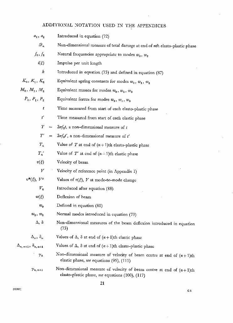
ADDITIONAL NOTATION
~1 ~ ~2
fo,f
k
Ko, K1,
Mo, M1,
P0, P1,
t
t'
T
T'
T£
V
V*
Vo
Wo
Wl, ~)2
A,
An, .n+l ~ ~g, n+ l
7n
(91391)
USED IN THE APPENDICES
Introduced in equation (72)
Non-dimensional measure of total damage at end of nth elasto-plastic phase
Natural frequencies appropriate to modes Wo, w 2
Impulse per unit length
Introduced in equation (73) and defined in equation (87)
Equivalent spring constants for modes w0, wl, w 2
Equivalent masses for modes w0, wl, w 2
Equivalent forces for modes w0, wl, w 2
Time measured from start of each elasto-plastic phase
Time measured from start of each elastic phase
27rf2t, a non-dimensional measure of t
2~rfot', a non-dimensional measure of t'
Value of T at end of (n + 1)th elasto-plastic phase
Value of T' at end of (n + 1)th elastic phase
Velocity of beam
Velocity of reference point (in Appendix I)
Values of v(~), V at mode-to-mode change
Introduced after equation (88)
Deflexion of beam
Defined in equation (81)
Normal modes introduced in equation (73)
Non-dimensional measures of the beam deflexion introduced in equation (73)
Values of A, ~ at end of (n + 1)th elastic phase
Values of A, ~ at end of (n + 1)th elasto-plastic phase
Non-dimensional measure of velocky of beam centre at end of (n+ 1)th elastic phase, see equations (95), (111)
Non-dimensional measure of velocity of beam centre at end of (n+ 1)th elasto-plastic phase, see equations (100), (117)
21
C2

APPENDIX I
Dynamics of the Mode-to-Mode Change
For simplicity the discussion below is limited to the dynamics of the mode-to-mode change in a beam; the extension to the plate is straightforward.
In the elastic mode x(~), the velocity v(~) at any point may be expressed in terms of the velocity
V, say, of the reference point ~0:
v(£)- Vx(~) (66) x(~0) "
Similarly, in the plastic mode xv(~), the velocity v~(~) is given by
Vvx~)(~) (67) % ( ~ ) - ~ ( ~ 0 )
Now let v~(~) and V '* denote the values of v(~) and V at the maximum amplitude in the elastic mode, i.e. immediately prior to the introduction of the plastic mode, and let v~*(~) and V~ ~ denote the values of vp(~:) and V~ immediately after the introduction of the plastic mode. The problem is to determine the relationship betwen V~ ~: and V%
It is convenient to regard the velocity distribution v~(~) as the immediate result of a distributed. impulse applied to a stationary but deflected beam. The magnitude of this distributed impulse per unit length is given by
i(~) = lim p(~)3t, say 6t-->O
mv~(O - g ( 6 8 )
V%,x(O
g~( ~o) The effect of this impulsive pressure distribution p(~) on a beam constrained to deflect in the
plastic mode x~(~) may be readily determined from the analysis of Section 2.1 and equation (20). The equivalent impulsive force P~, is given by
. . = I d0 t x~Ag0)J
1 ~ . x~o(~)
The velocity V~o ~ is now given by
gP~St V ~ - M~,
V ~ fa mx(~)x.(~) d~ o X(£o)X~(~o)
f a m(~o(~:)? d~ o (x , , (~0)p
in virtue of equations (69) and (20).
(70)
22

Finally
¢ = V */V.fa ) 0 Cb "
X( o) f 0
(71)
APPENDIX II
Impulsive Damage in Simply Supported Beams: a Two-Term Soh#ion
The following analysis, though approximate, is an attempt to analyse in a simple engineering way
the complex dynamical interaction between the elastic and plastic behaviour which occurs after the
initial formation of a plastic hinge. The simply supported beam subjected to a sudden impulse
has been chosen on grounds of convenience; the general method of solution could, however, be
applied to any beam which exhibits a single plastic hinge at failure, and any time-wise variation of
the impulsive loading; beams exhibiting more than one hinge would require a more complex
analysis. The results indicate that the introduction of the parameters /x and ~ leads to a more accurate estimation of damage.
A. 1. Characteristics of the Assumed Beam Modes.
The beam deflects symmetrically about the centre and it is therefore sufficient to consider the behaviour of half the beam, and for convenience we take the origin at one of the simply supported ends. The underlying assumption of the following analysis is that the deflexion w of the half-beam
may be expressed at all times as a linear combination of the elastic and plastic modes introduced in Sections 2 and 3, i.e.
w(~) = a 1 sin 7r~/a + a2~ (72)
where a 1 and az are functions of time (to be determined) and 0 ~< ~ ~< ½a.
The analysis is considerably simplified by recombining the elastic and plastic modes into normal modes as follows:
w(~) = k{(A+ 3)wz - 3w2} (73) where
w l = 2 /a,
w 2 = (24~/a-zr ~ sin ~# /a ) / (12 -~ ) , (74)
and k is a disposable constant introduced for convenience.
It is to be noted that w 1 and w~ are equal to unity at the reference point ~ = ½-a, and accordingly
kA is the deflexion of the centre of the beam. The grouping of terms in w 2 was obtained from the condition
f al2 wiw2 d~ = O. 0
23

Now the effect of the sudden impulse is to impart a certain velocity distribution to the undeflected beam. Thereafter each half-beam is unloaded, apart from the bending moment ~/g at ~ = ½a which may be elastic (Jd < d@) or plastic (Jg = ~ y ) .
Associated with each of the normal modes w 1 and w s there is an 'equivalent mass' M 1 and M2 ; an 'equivalent spring constant' K 1 and K s , and an 'equivalent force' P1 and Ps which thus depends only on the magnitude of the central moment Jg. Substitution of equations (74) into equations (1), (2), (3) gives
M1 = m. /6 / (75)
J K1 0
in virtue of the fact that w 1 is a rigid-body displacement, and
J 2 J Z / a
where a dash denotes differentiation with respect to ~. Also
(76)
M s = ma(~r ~ - 96) 4(12_7r2)s (77)
Elrr s Ks - 4a8(12_ ~r2) s (78)
Ps =
and finally
24J~ a(12 -
(79)
4rrsf2 ~ = g K s / M 2 ]
_ gEIrrS j (80)
ma4(rr ~ - 96)"
The change of sign in the expressions for P1 and Ps is due to the change in the direction of measurement of positive w 1 and w2, which results from the minus sign in equation (73).
In the initiM purely elastic state
w(~) = k A w o , say ] where ) (81)
w0 = s i n - ~ / a
and the corresponding values of the 'equivalent mass', etc. for the half-beam are given by equation (7):
M o = rea l4 (82)
zr~ E I K 0 - 4a 3 (83)
and Po = p a / ~ (84)
47rsf0 ~ = g EITr~ m a 4 . (85)
24
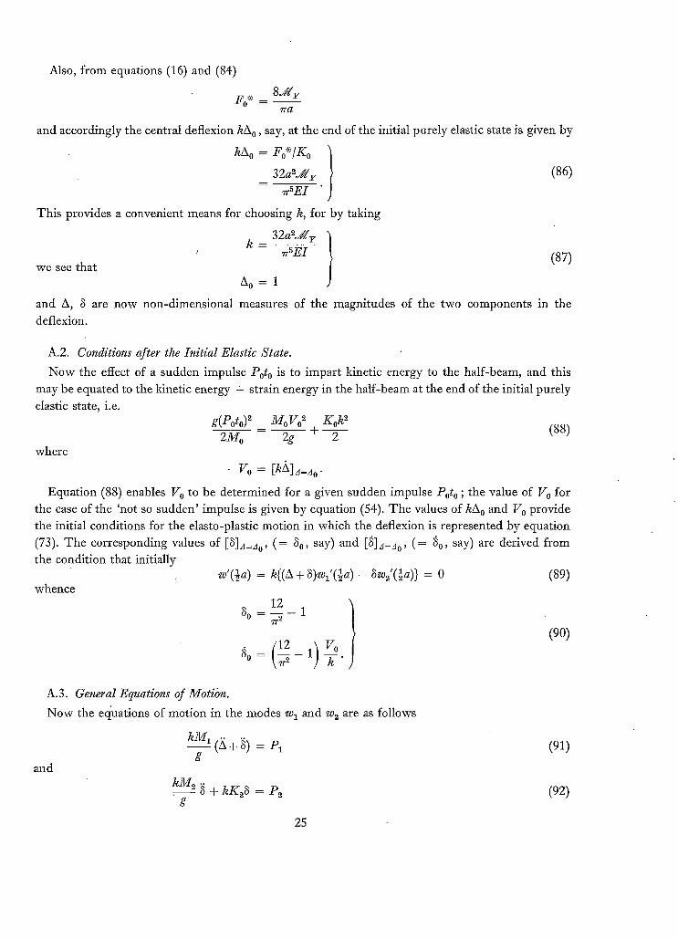
Also, from equations (16) and (84)
8d/@ F o * _
I r a
and accordingly the central deflexion kAo, say, at the end of the initial purely elastic state is given by
kA o = Fo*/K o
32a~d{r (86)
zrS E I
This provides a convenient means for choosing k, for by taking
k - 32a2d/@ ' zrSEI (87)
we see that A 0 = 1
and A, 8 are now non-dimensional measures of the magnitudes of the two components in the deflexion.
A.2. Conditions after the Initial Elastic State.
Now the effect of a sudden impulse Poto is to impart kinetic energy to the half-beam, and this may be equated to the kinetic energy + strain energy in the half-beam at the end of the initial purely elastic state, i.e.
g(P°t°)~ M°V°Z K°ka (88) = + 2
where
Vo = [khL= o.
Equation (88) enables V o to be determined for a given sudden impulse Poto ; the value of V o for the case of the 'not so sudden' impulse is given by equation (54). The values of hA o and V 0 provide the initial conditions for the elasto-plastic motion in which the deflexion is represented by equation
(73). The corresponding values of [8]~=Ao, (= 80, say) and [8]~=Jo' (= 80, say) are derived from
w'(½a) = k{(A + 8)wl'(½a ) - 8w((½a)} = 0 (89)
1.1 } 8 o = or- ~ -
go = W"
the condition that initially
whence
(90)
A.3. General Equations of Motion.
Now the equations of motion in the modes w 1 and w 2 are as follows
kM~ (.A + .~) = p~ g
and
kM2 .~ + kK28 = P2 g
(91)
(92)
25

where P1 and P~ are given by equations (76) and (79) with ~ = ~//d r provided the central hinge
angle is increasing. If at any stage in the motion the rate of opening of the central hinge fails to zero, the hinge may 'lock' and the possibility of a further purely elastic phase in the motion must be considered.
A.4. The First Elasto-Plastic Phase.
The solution of equations (91) and (92) subject to the boundary conditions (90) may be written non-dimensionally in the form
69' 0T 3(w 4 -96) T ~ A + ~ = A o + g o + ~.a 167r ~ (93)
and
( 1 2 - 7r2] {3(1-cos T ) + ½9'0 sin T} (94) 3 = g o c ° s T + \ ~r 3 }
where 9'0 and T have been introduced for convenience and are given by
9"O = k f 2
T 2~rf~t
(95)
and t is assumed zero at the start of the motion when A = A o = 1.
Equations (93) and (94) are valid only as long as @'(½a) is positive, i.e. up to such time when
(12) ( 2 x + 8 ) - 8 = o. (96)
Substitution of equations (93) and (94) in (96) and writing T o for the critical value of T gives the following relation for determining T o in terms of 9'0:
w * - 96] 16 ] T° - (27r-6) sin T O
9'0 = 1 - cos To (97)
Let us now denote by Aol, 8ol the values of A, 8 at time To, and by Aol , 8ol the values of A, 8 at time T o. Let us also introduce 9'ol {el. equation (95)} such that Aol = 9'olf2. Equations (93), (94) and (96) then give
69'oTo 3(~ 4 - 96) Aox + 3ol = Ao + 3o + - w~ 16w~ To ~ (98)
and
(12 - rr~ {3(1-cos To) + ½Yo sin To} 3o1= ~ o c ° s T o + \ ~r ~ ]
9 ,01 = AO1/f2
9% = 9 ' ° - I , 16 ] T°.
(99)
(100)
26

Equations (98) to (100) provide the initial conditions for the behaviour of the beam in the purely
elastic phase which occurs after time T O . The amount of damage suffered by the complete beam at time T O depends on the angular movement of the plastic hinge, and this may be readily expressed
non-dimensionally--as in the main text--as the ratio of the corresponding permanent central
deflexion/k. This non-dimensional measure of the damage is denoted by the symbol ~1 and it is to
be noted that further damage may occur before the beam finally comes to rest. Thus we find
(12) ~1 = A o i + 3 o l - ~ 3ol
6 = 7r ~ ((2~r - 6) (1 - cos To) + ~/o( To - sin To) - (~r 4 - 96) To2/32}. (101)
A.5. The Second Elastic Phase.
Now in the elastic phase which occurs after time T O the equations of motion are (91) and (92) in which d£ is at present unknown, together with equation (96) which expressed the constancy of the central hinge angle. The moment ~¢d may be eliminated from equations (91) and (92) by writing
where
M1 (Z~ -~- '~) P1 (M2 ~ _}_ K-93) (102) Y = E - Z
P2
Similarly (? '+ 3) may be eliminated from equations (96) and (102) to yield
+ 4~f0~3 = 0
whose solution, which satisfies the initial conditions (99) and (100), is given by
{~01] 3 = 3ol cos 2rrfot' + \2E[o] sin 2rrfot'
where
t' = t To 2%
which is zero at the start of the elastic phase. Substitution of equation (104) into equation (96) gives, on integration,
A = ?'o1+ ] - 2 - ~ (3-3ol ) .
(103)
- .
(104)
32 } 16yol sin To' 1 7r(12-- ~r 2) 3°1 cos To' - 7r~/(~, _ 96) = 0. (106)
27
Finally, the range of validity of equations (104) and (105) may be established by determining J d from equations (91) or (92), and equating this to J d g . It follows that the elastic phase ceases at time t' = To'/(2rrfo), say, where
(105)

At this critical value of t', which heralds the appearance of a further elasto-plastic phase, the displacement and velocity of the beam are given by
3 = 31, say
( t = 8ol cos T o' + 2 7 r ~ - - - 96)
8 = 81, say
= 8ol cos T o' - 2wfo3ol sin T o'
A = A1, say
= A01+ ~ (81-801)
/k = /kx, say
qr 2
Vol sin To' ~ (107)
(108)
(109)
(110)
A.6. The Second Elasto-Plastic Phase.
Equations (107) to (110) provide the initial conditions for the beam in the elasto-plastic phase for which the equations of motion are (91) and (92) w i t h / g = / g g . The solution of these equations may be writ ten non-dimensionally in the form
and
where
6y 1T 3(w ~ - 9 6 ) T 2 A -[- 8 = A I + 8 1 + " wa 16ws (111)
(12 - ~2~ {3(1-cos T) + ½71 sin T} (112) S = 31 cos T + \ ~ ]
t 2 w x / ( ~ - 96)/ =VolC°S T o ' - ~ 1 2 - ~ ' ~ J 8°1 sin T O ' (113)
and a fresh origin, zero at the start of this elasto-plastic phase, has been chosen for T ( = 2wf#). Equations (111) and (112) are valid only as long as ~b'(½a) is positive; i.e. up to such time when
equation (96) is satisfied. I t may then be shown that this critical value of T, denoted by T1, is determined from the relation:
y l ( 1 - c o s T 1 ) - 6 sin T1 ( ~ - 96) ( 2~ "8
16 T1 + \12 - ~r ~] 81 sin T 1 = 0. (114)
28

Let us now denote by A12 , 813 the values of A, 8 at time T1, and by zX12, 81~ the values of/~, 8 at time T 1. Let us also introduce 7~2 {cf. equation (100)} such that /~19. = 71ff~. Equations (111), (112) and (96) then give
6y l r l 3(~4- 96) rl~ (115) A12 + 812 = k I + 81 + 7 r 7 16~r a
and
/12 - ~re~ {3(1 - cos /'1) + ½Yl sin T1} (116) 812 = 81 cos T 1+ \ ~r a ]
[ : ' - % r l = Y l - \ 16 ]
(117)
Similarly, the non-dimensional measure of the total damage incurred during the first two elasto- plastic phases is given by
( 1 2 ) ~@2 = Al~ + 81~ - 1 - 2 - ~ 812" (118)
A.7. Analysis for Further Elasto-Plastic Phases.
Whether or not this is the final measure of the total damage depends on whether there is a further elasto-plastic phase. Following an analysis similar to that of Section A.5, it will be seen that a further elasto-plastic phase will occur if a term T z' exists which satisfies the equation
{ } 16y12 sin TI' 32 813 cos T 1' 1 ,r(1T_~r~) 7r%/(Tr4_96) - 0. (119)
The cycle of operations for determining ~a may now be repeated. Apart from a unit increase in each suffix, it follows an identical pattern to that used to determine ~ in terms of A01,801, Y0t. If we iiltroduce the notation -+ to mean 'is a function of' we may write the necessary steps in the
following symbolic form:
To' -+ 801, Y01
ml, 81, Yl -+ m01, 801, ~01, To"
T1 -+ 81, ~'1
A12,812, Y12 -~ A1, 81, Yl, 711
N2 -+ A12, 813
711' -> 812, ~12
etc.
[equation (106)]
[equations (107), (109), (113)]
[equation (114)]
[equations (115), (116), (117)]
[equation (118)] t
[equation (119)]
29

A.8. Comparison with Present Simplified Theory and Previous Theory. According to the simplified theory presented in the main body of the report the damage due to a
sudden impulse is given by equation (57),
Also, from equation (54)
= z~2(2=2j2_ ~).
g o = ~
_ 2~foPo [ 4~2fo~to ~ - [Fo*~2tl/2 Ko t \ P o / J
so that 2 2 2 2 2 1 z d = 8 . k fo (2~- j - ~ )
and hence
= 8~2" f0
Nowf~, .f0 are given by equations (80), (85) and t~, ~ by equation (25); hence
@ = 1. 096 702. (120)
The relationship between ~ and 702 is therefore linear and it provides a convenient basis for comparison with the more accurate two-term solution and with previous theory in which the factors t* and ~ were inherently assumed equal to unity, and for which
= 0. 876 703 . (121)
The comparison is shown in Fig. 12.
t It is, of course, unnecessary to determine ~ when T~_ 1' exists.
30

E=C>
FIG. 1. Equivalent mass-spring system.
ST~E55/
$TP, AI N FIG. 2.
BEN01NG MOMENT Y
GURVATU~E
FIG, 3.
FIGS. 2 and 3. Elasto-plastic relations considered in Section 3.
STRESS / STRAIN
FIG. 4. Elasto-plastic relation considered in Section 3.
LOAD
/ SIMPLY SUPPOP~TED
CENTRAL DF-FLVXlON
FIG. 5. Load vs. central deflexion for statically loaded beams.
N
q a
i. / Z ta 4-
o
?_ . . . . . . . . . .
o 0 0'?. 0"4- 0 ' 6 0 ' 8
N O N - D I M E N . S I O N A L TIME~ ~d
I 7.: = N O N - D I M E N S I O N A L
APPL IE~ FORGE
/
J
I'0 I '?-
2 : = 0 " 8
1"4-
FIG. 6. Damage curves, ( ~ , -r relationship for various values of X)"
B
J Lg" < ~6 {3
J < Z _(2 4
i Z z o Z
0 0 0"?- 0'~" 0"6 0"8 ;'0 I'Z I'LF
N O N - D I t " I E N S l O N A L "I ' IME~ "IZ
FIG. 7. Damage curves, ( ~ , ~- relationship for various values of of).
32

P-O ¢
' ~ = 7 - 0
. ~ Ig X = ~-'O
~ ,~ '.111/ ~ ~ ~ ~
121
0 Z
o I " " ' ~ ' - , 0 0'?- O. ":1- 0 ' 6 0 '8 I '0 I '& 1.4- o o
N O N - D I M E N S I O N A L -rlN¢'.~ "*C
FIO. 8. Damage curves, (~@/J~, ~- relationship for various values of X).
FO&CE
DISPLACEMENT
Fie. 9. Non-linear force-displacement relationship.
STRESS
/11 0 S'I '~AI N
Fro. 10. Linear work-hardening.
33

ff
0 .J
Z 0
Z
o Z
8
G
o o
FIc. 11.
0(= O'B
/ /
('s~'E ~$. (6a)')
/ , i
. S y 0 "? O ' ~ O'G O'S I'O
N O N - E) IMENSIONAL IMPULSE~
1.2. I'@
Damage due to sudden impulse, (~ , J relationship for various values of c~).
8
IE
~6 Z o
ul Z
0 z
,,/
/
PP-.EVIOU5 THEORY ( ~ = 'e= t )
, /
/
o IO
NON-DIMENSIONAL ('VELOCITY) e AT OIMSET OF" 'VlEL[3, ~
FIG. 12. Comparisons of ~ , 703 relationships.
(91391) W t . 66/2301 K.5 5]65 Hw.
34

Publications of the Aeronautical Research Council
A N N U A L T E C H N I C A L R E P O R T S O F T H E A E R O N A U T I C A L R E S E A R C H C O U N C I L ( B O U N D V O L U M E S )
x945 Vol. I. Aero and Hydrodynamics, Aerof0ils. £6 ios. (£6 I3S. 6d.) Vol. II. Aircraft, Airscrews, Controls. £6 ios. (£6 I3s. 6d.) Vol. III. Flutter and Vibration, Instruments, Miscellaneous, Parachutes, Plates and Panels, Propulsion.
£6 los. (£6 I3s. 6d.) Vol. IV. Stability, Structures, Wind Tunnels, Wind Tunnel Technique. £6 ros. (£6 I3S. 3d.)
x946 Vol. I. Accidents, Aerodynamics, Aerofoils and Hydrofoils. £8 8s. (£8 i is. 9d.) Vol. II. Airscrews, Cabin Cooling, Chemical Hazards, Controls, Flames, Flutter, Helicopters, Instruments and
Instrumentation, Interference, Jets, Miscellaneous, Parachutes. £8 8s. (£8 I Is. 3d.) Vol. I IL Performance, Propulsion, Seaplanes, Stability, Structures, Wind Tunnels. £8 8s. (£8 I Is. 6d.)
x947 Vol. I. Aerodynamics, Aerofoils, Aircraft. £8 8s. (£8 x is. 9d.) Vol. II. Airscrews and Rotors, Controls, Flutter, Materials, Miscellaneous, Parachutes, Propulsion, Seaplanes,
Stability, Structures, Take-off and Landing. £8 8s. (£8 I Is. 9d.)
t948 Vol. L Aerodynamics, Aerofoils, Aircraft, Airscrews, Controls, Flutter and Vibration, Helicopters, Instruments, Propulsion, Seaplane, Stability, Structures, Wind Tunnels. £6 ios. (£6 I3s. 3d.)
Vol. II. Aerodynamics, Aerofoils, Aircraft, Airscrews, Controls, Flutter and Vibration, Helicopters, Instruments, Propulsion, Seaplane, Stability, StrUctures, Wind Tunnels. £5 los. (£5 I3S. 3d.)
x949 Vol. I. Aerodynamics, Aerofoils. £5 ios. (£5 x3s. 3d.) Vol. II. Aircraft, Controls, Flutter and Vibration, Helicopters, Instruments, Materials, Seaplanes, Structures,
Wind Tunnels. £5 ios. (£5 I3s.)
x95o Vol. I. Aerodynamics, Aer'ofoils, Aircraft. £5 x2s. 6d. (£5 i6s.) Vol. II. Apparatus, Flutter and Vibration, Meteorology, Panels, Performance, Rotorcraft, Seaplanes.
£4 (£4 3s.} Vol. III. Stability and Control, Structures, Thermodynamics, Visual Aids, Wind Tunnels. £4 (£4 2s. 9d.)
x951 Vol. I. Aerodynamics, Aerofoils. £6 Ios. (£6 I3s. 3d.) Vol. II. Compressors and Turbines, Flutter, Instruments, Mathematics, Ropes, Rotorcraft, Stability and
Control, Structures, Wind Ttmnels. £5 los. (£5 I3S. 3d.)
x952 Vol. I. Aerodynamics, Aerofoils. £8 8s. (£8 IXS. 3d.) Vol. II. Aircraft, Bodies, Compressors, Controls, Equipment, Flutter and Oscillation, Rotorcraft, Seaplanes,
Structures. £5 los. (£5 I3S.)
I953 Vol. I. Aerodynamics, Aerofoils and Wings, Aircraft, Compressors and Turbines, Controls. £6 (£6 3s. 3d.) Vol. II. Flutter and Oscillation, Gusts, Helicopters, Performance, Seaplanes, Stability, Structures, Thermo-
dynamics, Turbulence. £5 5 s. (£5 8s. 3d.)
I954 Aero and Hydrodynamics, Aerofoils, Arrester gear, Compressors and Turbines, Flutter, Materials, Performance, Rotorcraft, Stability and Control, Structures. £7 7s. (£7 ios. 6d.)
Special Volumes Vol. I. Aero and Hydrodynamics, Aerofoils, Controls, Flutter, Kites, Parachutes, Performance, Propulsion,
Stability. £6 6s. (£6 9s.) Vol. II. Aero and Hydrodynamics, Aerofoils, Airscrews, Controls, Flutter, Materials, Miscellaneous, Parachutes,
Propulsion, Stability, Structures. £7 7s. (£7 ios.) Vol. III. Aero and Hydrodynamics, Aerofoils, Airscrews, Controls, Flutter, Kites, Miscellaneous, Parachutes,
Propulsion, Seaplanes, Stability, Structures, Test Equipment. £9 9s. (£9 I2S. 9d.)
Reviews of the Aeronautical Research Council I949-54 5s. (Ss. 5d.)
Index to all Reports and Memoranda published in the Annual Technical Reports I9O9-Z947 R. & M. z6oo (out of print)
Indexes to the Reports and Memoranda of the Aeronautical Research Council Between Nos. 245x-2549: R. & M. No. 2550 2s. 6d. (2s. 9d.); Between Nos. 2651-2749: R. & M. No. 2750 2s. 6d. (2s. 9d.); Between Nos. 2751-2849: R. & M. No. 2850 2s. 6d. (2s. 9d.); Between Nos. 285x-2949: R. & M. No. 2950 3 s. (3s. 3d.); Between Nos. 295I-3O49: R. & M. No. 3050 3s. 6d. (3s. 9d.); Between Nos. 3o51-3149: R. & M. No. 315o 3s. 6d. (3s. 9d.); Between Nos. 3151-3249: R. & M. No. 325 o 3s. 6d. (3s. 9d.); Between Nos. 325z-3349: R. & M.
No. 335o 3s. 6d. (3s. iod.)
Prices in brackets include postage
Government publications can be purchased over the counter or by post from the Government Bookshops in London~ Edinburgh, Cardiff, Belfast, Manchester, Birmingham and Bristol, or through anybooksel ler

R. & M. No. 3408
© Crown copyright 1965
Printed and published by HER MAJESTY'S STATIONERY OFFICE
To be purchased from York House, Kingsway, London w.c.z
423 Oxford Street, London w.x I3A Castle Street, Edinburgh 2
xo9 St. Mary Street, Cardiff 39 King Street, Manchester 2
50 Fairfax Street, Bristol x 35 Smallbrook, Ringway, Birmingham 5
80 Chichester Street, Belfast x or through any bookseller
Printed in England
R. & M. No. 3408
S.O. Code No. 23-3408