chap ter display devices 4 - itx learning · 2012-10-22 · crt liquid crystal display led displays...
TRANSCRIPT
Display Devices
THE FOLLOWING COMPTIA A+ 220-801 OBJECTIVES ARE COVERED IN THIS CHAPTER:
� 1.10 Given a scenario, evaluate types and features of
display devices.
� Types
� CRT
� LCD
� LED
� Plasma
� Projector
� OLED
� Refresh rates
� Resolution
� Native resolution
� Brightness/lumens
� Analog vs. digital
� Privacy/antiglare filters
� Multiple displays
Chapter
4
324059c04.indd 197324059c04.indd 197 8/17/12 9:20 AM8/17/12 9:20 AM

The primary method of getting information out of a computer is to use a computer video display unit (VDU). Display systems convert computer signals into text and pictures and display
them on a TV-like screen. As a matter of fact, the fi rst personal computers used television screens because it was simpler to use an existing display technology rather than to develop a new one. Various types of computer displays are in use today, including the TV. Most all of them, projection systems as well, use the same legacy cathode ray tube ( CRT ) technology found in conventional television sets or the liquid crystal display ( LCD ) technology found on nearly all laptop, notebook, and palmtop computers. In fact, it is rare to see a desktop monitor based on CRT technology sold with a computer today. Generally only high-end specialized units (used for enhanced clarity and video performance) are CRT-based. This chapter introduces you to concepts surrounding display units used with personal com-puter systems. The previous chapter detailed the technology behind the adapters, interfaces, and connectors used in computer graphics. Other topics covered in this chapter include characteristics of display standards, such as the resolutions and color densities of VGA and the standards that sprung from it, and settings common to most display devices.
Understanding Display Types and Settings Most display systems work the same way. First, the computer sends a signal to a device called the video adapter — an expansion board installed in an expansion bus slot or the equivalent circuitry integrated into the motherboard—telling it to display a particular graphic or character. The adapter then renders the character for the display—that is, it converts the single instruction into several instructions that tell the display device how to draw the graphic—and sends the instructions to the display device, based on the con-nection technology between the two. The primary differences after that are in the type of video adapter you are using (digital or analog) and the type of display (CRT, LCD, projector, etc.). We’ll talk about some of these differences now.
Video Display Types
To truly understand the video display arena, you must be introduced to a few terms and con-cepts that you may not be familiar with. The legacy digital transistor-transistor logic (TTL) and the analog technologies that began with video graphics array (VGA) were once the two
324059c04.indd 198324059c04.indd 198 8/17/12 9:20 AM8/17/12 9:20 AM

Understanding Display Types and Settings 199
broad categories of video technologies. These categories have nothing to do with the makeup of the VDU but instead how the graphics adapter communicates with the VDU. You will read about many of the VGA technologies in coming sections of this chapter. First, however, let’s explore the different VDU types:
� CRT
� Liquid crystal display
� LED displays
� Plasma
� OLED
� Projection systems
CRT Displays
Legacy and today’s specialty computer monitors contain a CRT. In a CRT, a device called an electron gun shoots a beam of electrons toward the back side of the monitor screen (see Figure 4.1). Color CRTs often use three guns, one each for red, green, and blue image components. The back of the screen is coated with special chemical dots called phosphors (often zinc sulfi de combined with other elements for color variation, but no phosphorus, ironically) that glow when electrons strike them.
F I GU R E 4 .1 Cutaway of a CRT monitor
Scan magnets
Electron gun
Electron beam
Monitor case
Monitor screen
The beam of electrons scans across the monitor from left to right, as you face it, and top to bottom in a raster pattern to create the image. A special metallic screen called a shadow mask (in most implementations) has holes spaced and angled in an extremely precise manner. For color CRTs that employ shadow masks, a trio of dot phosphors is often grouped in a triangle for each hardware picture element. The separate electron beams that control red, green, and
324059c04.indd 199324059c04.indd 199 8/17/12 9:20 AM8/17/12 9:20 AM

200 Chapter 4 � Display Devices
blue strike only their own phosphors at the correct angle to cause them to glow. The glow of the phosphors decays very quickly, requiring the electron beam’s regular return to each phos-phor to sustain the glow. The more dot phosphors that are placed in a given area, the better the image quality at higher resolutions.
There are two ways to measure a CRT monitor’s image quality: dot pitch and resolution. Dot pitch is a physical characteristic of the monitor hardware, but resolution is confi gurable through software.
Dot pitch Dot pitch is the measurement between the same spot in two vertically adjacent dot trios. In other words, it’s the height of the trio added to the distance between the closest extremes of it and the next trio above or below it. Expressed in millimeters or dots per inch, the dot pitch tells how “sharp” the picture can be. The lower the measurement in millimeters or the higher the number of dots per inch, the closer together the phosphors are, and as a result, the sharper the image can be. An average dot pitch is 0.28mm to 0.32mm. Anything closer than 0.28mm is con-sidered exceptional. Dot pitch in the fl at-panel arena translates to the display’s native resolution, discussed later in this chapter. Essentially, software-pixel placement is limited to the hardware’s transistor placement, leading to one optimal resolution for each LCD. The transistors that make up the hardware’s picture elements are discussed later in the section “Liquid Crystal Displays.”
Resolution Resolution is defi ned by how many software picture elements (pixels) are used to draw the screen. An advantage of higher resolutions is that more information can be dis-played in the same screen area. A disadvantage is that the same objects and text displayed at a higher resolution appear smaller and might be harder to see. Up to a point, the added crisp-ness of higher resolutions displayed on high-quality monitors compensates for the negative aspects. The resolution is described in terms of the visible image’s dimensions, which indicate how many rows and columns of pixels are used to draw the screen. For example, a resolution of 1024 n 768 means 1024 pixels across (columns) and 768 pixels down (rows) were used to draw the pixel matrix. The video technology in this example would use 1024 n 768 = 786,432 pixels to draw the screen. Resolution is a software setting that is common among CRTs, LCDs, and projection systems as well as other display devices.
Resolution’s Memory Requirement
Video memory is used to store rendered screen images. The memory required for a screen image varies with the color depth, which is defi ned as the number of colors in which each pixel can be displayed. A palette with a 24-bit color depth is capable of displaying each pixel in one of 2 24 = 16,777,216 distinct colors.
In the preceding example, if you were using 24-bit graphics, meaning each pixel requires 24 bits of memory to store that one screen element, 786,432 pixels would require 18,874,368 bits, or 2,359,296 bytes. Because this boils down to 2.25MB, an early (bordering on ancient) video adapter with only 2MB of RAM would not be capa-ble of such resolution at 24 bits per pixel. Today’s adapters have absolutely no trouble displaying such a resolution with a 24- or 32-bit color depth. In fact, they store many screens at a time in order to allow the display of full-motion video.
324059c04.indd 200324059c04.indd 200 8/17/12 9:20 AM8/17/12 9:20 AM

Understanding Display Types and Settings 201
Liquid Crystal Displays
Portable computers were originally designed to be compact versions of their bigger desk-top cousins. They crammed all the components of the big desktop computers into a small, suitcase-like box called (laughably) a portable computer. No matter what the designers did to reduce the size of the computer, the display remained as large as the desktop version’s—that is, until an inventor found that when he passed an electric current through a semi-crystalline liquid, the crystals aligned themselves with the current. It was found that by combining tran-sistors with these liquid crystals, patterns could be formed. These patterns could be combined to represent numbers or letters. The fi rst application of these liquid crystal displays was the LCD watch. It was rather bulky, but it was cool.
As LCD elements got smaller, the detail of the patterns became greater, until one day some-one thought to make a computer screen out of several of these elements. This screen was very light compared to computer monitors of the day, and it consumed relatively little power. It could easily be added to a portable computer to reduce the weight by as much as 30 pounds. As the components got smaller, so did the computer, and the laptop computer was born.
LCDs are not just limited to laptops; desktop versions of LCD displays and their offshoots are practically all that are seen today. Additionally, the home television market has been enjoy-ing the LCD as a competitor of plasma for years. LCDs used with desktop computer systems use the same technology as their laptop counterparts but potentially on a much larger scale.
These external LCDs are available in either analog or digital interfaces. The analog interface is exactly the same as the VGA interface that was used for analog CRT monitors. Internal digital signals from the computer are rendered and output as analog signals by the video card and are then sent along the same 15-pin connector and associated cable as was used with analog CRT monitors. Digital LCDs with a digital interface, on the other hand, require no analog modulation by the graphics adapter. They require the video card to sup-port digital output using a different interface, such as DVI, for instance. The advantage is that because the video signal never changes from digital to analog, there is less chance of interference and no conversion-related quality loss. Digital displays are generally sharper than their analog counterparts.
Two major types of LCD displays have been implemented over the years: active-matrix screens and passive-matrix screens. Another type, dual scan, is a passive-matrix variant. The main differences lie in the quality of the image. However, when used with computers, each type uses lighting behind the LCD panel (backlighting) to make the screen easier to view. Conventional LCD panels have one or more fl uorescent bulbs as backlights. See the section “LED Displays” for details on a better type of backlight. The following discussions highlight the main differences among the pixel-addressing variants.
Active matrix An active-matrix screen is made up of several independent LCD pixels. A transistor at each pixel location, when switched among various levels, activates two opposing electrodes that align the pixel’s crystals and alter the passage of light at that location to pro-duce hundreds or thousands of shades. The front electrode, at least, must be clear. This type of display is very crisp and easy to look at through nearly all oblique angles, and it does not require constant refreshing to maintain an image because transistors conduct current in only one direction and the pixel acts like a capacitor by holding its charge until it is refreshed with new information. Higher refresh rates are not for prevention of pixel discharge, as in the case
324059c04.indd 201324059c04.indd 201 8/17/12 9:20 AM8/17/12 9:20 AM

202 Chapter 4 � Display Devices
of CRTs, plasma displays, and passive-matrix LCDs. Higher rates only result in better video quality, not static-image quality.
The major disadvantage of an active-matrix screen is that it requires larger amounts of power to operate all the transistors, one for each grayscale pixel or each red, green, and blue subpixel. Even with the backlight turned off, the screen can still consume battery power at an alarming rate, even more so when conventional fl uorescent backlights are employed. The vast majority of LCDs manufactured today are based on active-matrix technology.
Passive matrix A passive-matrix display does not have a dedicated transistor for each pixel or subpixel but instead a matrix of conductive traces. In simplifi ed terms for a single pixel, when the display is instructed to change the crystalline alignment of a particular pixel, it sends a signal across the x- and y-coordinate traces that intersect at that pixel, thus turning it on. Figure 4.2 illustrates this concept. More realistically, circuits controlling the rows fi re in series to refresh or newly activate pixels on each row in succession.
F I GU R E 4 . 2 A passive-matrix display
To lightthis pixel . . . we send current on these wires.
The circuits controlling the columns are synchronized to fi re when that row’s transis-tor is active and only for the pixels that should be affected on that row. Once a pixel’s charge is gone, the pixel begins to return to normal, or decay, requiring a refresh to make it appear static. Angles of visibility and response times (the time to change a pixel) suffer greatly with passive-matrix LCDs. Because neighboring pixels can be affected through a sort of “crosstalk,” passive-matrix displays can look a bit “muddy.”
Dual scan Dual scan is a variation of the passive-matrix display. The classic passive-matrix screen is split in half to implement a dual-scan display. Each half of the display is refreshed separately, leading to increased quality. Although dual scan improves on the quality of con-ventional passive-matrix displays, it cannot rival the quality produced by active matrix.
324059c04.indd 202324059c04.indd 202 8/17/12 9:20 AM8/17/12 9:20 AM

Understanding Display Types and Settings 203
The main differences between active matrix and typical passive matrix are image quality and viewing angle. Because the computer takes hundreds of milliseconds to change a pixel in passive-matrix displays (compared with tens of milliseconds or less in active-matrix displays), the response of the screen to rapid changes is poor, causing, for example, an effect known as submarining : On a computer with a passive-matrix display, if you move the mouse pointer rapidly from one location to another, it will disappear from the fi rst location and reappear in the new location without appearing anywhere in between. The poor response rate of passive-matrix displays also makes them suboptimal for displaying video.
If you move toward the side of a passive-matrix LCD, you eventually notice the display turning dark. In contrast, active-matrix LCDs have a viewing angle wider than 179 degrees. In fact, if you didn’t know better, you’d think a passive-matrix display was a standard display with a privacy fi lter on it. A privacy fi lter is a panel that fi ts over the front of a display and, through a polarization affect, intentionally limits the viewing angle of the monitor. The fi lters were used with CRTs and continue to be produced for the variety of LCD and plasma panels being used as computer monitors. These same fi lters, as well as specialty versions, can act as antiglare fi lters , brightening and clarifying the image appearing on the monitor’s screen.
We’ll discuss additional concepts that apply to LCDs and other fl at-panel displays later in this chapter.
LED Displays
A source of confusion for users and industry professionals alike, LED displays are merely LCD panels with light emitting diodes (LEDs) as light sources instead of the fl uorescent bulbs used by conventional LCD monitors. No doubt, the new technology would not be nearly as marketable if they were referred to merely as LCDs. The general consumer would not rush to purchase a new display that goes by the same name as their current display. Nevertheless, calling these monitors LED displays is analogous to calling the conventional LCD monitors fl uorescent displays; it’s simply the backlight source, not the display technology.
Because there are many individually controlled LEDs in an LED display, sometimes as many as there are transistors in the LCD panel, the image can be intelligently backlit to enhance the quality of the picture. Additionally, there is no need for laptops with LED displays to convert the DC power coming into the laptop to the AC needed to power traditional fl uo-rescent backlights because LEDs operate on DC power like the rest of the laptop. As a result, these systems have no inverter board (discussed later in Chapter 9, “Understanding Laptops”), which are the DC-to-AC conversion devices present in traditionally backlit laptop displays. LED displays rival plasma displays in clarity and variations in luminance. This variation is referred to as contrast ratio and is discussed later in this chapter.
Plasma Displays
The word plasma refers to a cloud of ionized (charged) particles—atoms and molecules with electrons in an unstable state. This electrical imbalance is used to create light from the changes in energy levels as they achieve balance. Plasma display panels (PDPs) create just such a cloud from an inert gas, such as neon, by placing electrodes in front of and behind sealed chambers full of the gas and vaporized mercury. This technology of running a current
324059c04.indd 203324059c04.indd 203 8/17/12 9:20 AM8/17/12 9:20 AM

204 Chapter 4 � Display Devices
through an inert gas to ionize it is shared with neon signs and fl uorescent bulbs. Because of the pressurized nature of the gas in the chambers, PDPs are not optimal for high-altitude use, leading to CRTs and LCDs being more popular for high-altitude applications, such as aboard aircraft, where PDPs can be heard to buzz the way fl uorescent bulbs sometimes do.
Because of the temporary emission of light that this process produces, plasma displays have more in common with CRTs than they do with LCDs. In fact, as with CRTs, phosphors are responsible for the creation of light in the shade of the three primary colors, red, green, and blue. Because the pixels produce their own light, no backlight is required with plasma displays, also a feature shared with CRTs. The phosphor chemicals in CRTs and PDPs can be “used up” over time, reducing the overall image quality. The heat generated by CRTs and PDPs can lead to a loss of phosphorescence in the phosphor chemicals, which results in images burning into the screen. Advancements in the chemistry of plasma phosphors have reduced this tendency in recent years.
The refresh rate for plasma displays has always been in the 600Hz range so that the decay of the glow of the cells within each pixel (subpixel) is not perceptible until such time as the image calls for that cell to turn off as well as to ensure fl uid video motion. See the section “Refresh Rate” later in this chapter for details on these concepts, but note that this rate is approximately 10 times that which is necessary to avoid the human eye’s perception of the glow’s decay. The result is a display that produces the state of the art in video motion fl uid-ity. Higher refresh rates in LCDs lead to an unwanted artifi cial or noncinematic quality to video known as the “soap-opera effect.” PDPs do not suffer from this effect.
PDPs can also produce deeper black colors than fl uorescent-backlit LCD panels because the backlight cannot be completely blocked by the liquid crystal, thus producing hues that are grayer than black. LCDs backlit with LEDs, however, are able to completely dim selec-tive areas or the entire image. Because of the relative cost-effectiveness to produce PDPs of the same size as a given LCD panel, plasma displays historically enjoyed more popularity in the larger-monitor market. That advantage is all but gone today, resulting in more LCDs being sold today than plasma displays.
OLED Displays
Organic light emitting diode ( OLED ) displays, unlike LED displays, really are the image-producing parts of the display, not just the light source. In much the same way as a plasma cell places an excitable material between two electrodes, OLEDs are self-contained cells that use the same principle to create light. An organic light-emitting compound forms the heart of the OLED and is placed between an anode and a cathode, which produce a current that runs through the electroluminescent compound, causing it to emit light. An OLED, then, is the combination of the compound and the electrodes on each side of it. The electrode in the back of the OLED cell is usually opaque, allowing a rich black display when the OLED cell is not lit. The front electrode should be transparent to allow the emission of light from the OLED.
If thin-fi lm electrodes and a fl exible compound are used to produce the OLEDs, an OLED display can be made fl exible, allowing it to function in novel applications where other display technologies could never. Because of the thin, lightweight nature of the panels, OLED displays can both replace existing heavy full-color LED signs, like the ones you might see in Las Vegas
324059c04.indd 204324059c04.indd 204 8/17/12 9:20 AM8/17/12 9:20 AM

Understanding Display Types and Settings 205
or even at your local car dealer’s lot, and carve out new markets, such as integration into clothing and multimedia advertisements on the sides of buses to replace and improve upon the static ads seen today.
LEDs create light and have been used in recent years for business, home, and automotive interior lighting and automotive headlamps. OLEDs are LEDs, organic as they may be, and produce light as well. They, too, have already made their way into the interior lighting mar-ket. Because OLEDs create the image in an OLED display and supply the light source, there is no need for a backlight with its additional power and space requirements, unlike in the case of LCD panels. Additionally, the contrast ratio of OLED displays exceeds that of LCD panels, regardless of backlight source. This means that in darker surroundings, OLED dis-plays produce better images than do LCD panels. Because OLEDs are highly refl ective, how-ever, quite a bit of research and development in optics has been required to produce fi lters and optical shielding for OLED displays. As unlikely as it seemed from early descriptions of OLED physics, true-black displays that are highly visible in all lighting conditions can now be developed using OLED technology. The foregoing discussion notwithstanding, double transparent-electrode OLEDs, with a sidelight for night viewing, have been demonstrated as a kind of “smart window.”
As with LCD panels, OLED panels can be classifi ed as active matrix (AMOLED) or passive matrix (PMOLED). As you might expect, AMOLED displays have better quality than PMOLED displays but, as a result, require more electrodes, a pair for each OLED. AMOLED displays have resolutions limited only by how small the OLEDs can be made, while the size and resolution of PMOLED displays are limited by other factors, such as the need to gang the electrodes for the OLEDs.
The power to drive an OLED display is, on average, less than that required for LCDs. However, as the image progresses toward all white, the power consumption can increase to two or three times that of an LCD panel. Energy effi ciency lies in future developments as well as the display of mostly darker images, which is a reason why darker text on lighter backgrounds may give way to the reverse, both in applications and online. For OLEDs, the display of black occurs by default when the OLED is not lit and requires no power at all.
Although the early materials used in OLEDs have demonstrated drastically shorter life spans than those used in LCD and plasma panels, the technology is improving and has given rise to compounds that allow commercially produced OLEDs to remain viable long past the life expectancy of other technologies. The cost of such panels will continue to decrease so that purchases by more than corporations and the elite can be expected. In early January 2012, LG unveiled a 55 g 5mm-thick OLED HDTV. Pricing was not immediately announced, although Samsung’s intent to rival LG’s model with a dual-core 55 g 3D version with pixel-to-pixel control was.
Two important enhancements to AMOLED technology have resulted in the development of the Super AMOLED and Super AMOLED Plus displays, both owing their existence to Samsung. The Super AMOLED display removes the standard touch sensor panel (TSP) found in the LCD and AMOLED displays and replaces it with an on-cell TSP that is fl at and applied directly to the front of the AMOLED panel, adding a mere thousandth of a millimeter to the panel’s thickness. The thinner TSP leads to a more visible screen in all lighting conditions and more sensitivity when used with touch panels.
324059c04.indd 205324059c04.indd 205 8/17/12 9:20 AM8/17/12 9:20 AM

206 Chapter 4 � Display Devices
The Super AMOLED Plus display uses the same TSP as the Super AMOLED display. One advantage it has over Super AMOLED is that it employs 1.5 times as many elements (subpixels) in each pixel, leading to a crisper display. Another advantage is that Super AMOLED Plus is 18 percent more energy effi cient compared with Super AMOLED. The Super AMOLED and Super AMOLED Plus displays also feature a longer lifetime than that of the standard AMOLED display.
Projection Systems
Another major category of display device is the video projection system, or projector. Portable projectors can be thought of as condensed video display units with a lighting system that proj-ects the VDU’s image onto a screen or other fl at surface for group viewing. Interactive white boards have become popular over the past decade to allow presenters to project an image onto the board as they use virtual markers to electronically draw on the displayed image. Remote participants can see the slide on their terminal as well as the markups made by the presenter. The presenter can see the same markups because the board transmits them to the computer to which the projector is attached, causing them to be displayed by the projector in real time.
To accommodate using portable units at variable distances from the projection surface, a focusing mechanism is included on the lens. Other adjustments, such as keystone, trapezoid, and pincushion, are provided through a menu system on many models as well as a way to rotate the image 180 $ for ceiling-mount applications.
Rear Projection
Another popular implementation of projection systems has been the rear-projection televi-sion, in which a projector is built into a cabinet behind a screen onto which the image is projected in reverse so that an observer in front of the TV can view the image correctly. Early rear-projection TVs as well as ceiling-mounted home-theater units used CRT tech-nology to drive three fi ltered light sources that worked together to create an RGB image.
Later rear-projection systems, including most modern portable projectors, implement LCD gates. These units shine a bright light through three LCD panels that adjust pixels in the same manner as an LCD monitor, except the projected image is formed as with the CRT projector by synchronizing the combination and projection of the red, green, and blue images onto the same surface.
Digital light processing (DLP) is another popular technology that keeps rear-projection TVs on the market and benefi ts portable projectors as well, allowing some projectors to be extremely small. Special DLP chips, referred to as optical semiconductors, have roughly as many rotatable mirrors on their surface as pixels in the display resolution. A light source and colored fi lter wheel or colored light sources are used to rapidly switch among primary, and sometimes secondary, colors in synchronization with the chip’s mirror positions, thousands of times per second.
Brightness
Projection systems are required to produce a lighted image and display it many feet away from the system. The inherent challenge to this paradigm is that ambient light tends to inter-fere with the image’s projection. One solution to this problem is to increase the brightness of
324059c04.indd 206324059c04.indd 206 8/17/12 9:20 AM8/17/12 9:20 AM
Understanding Display Types and Settings 207
the image being projected. This brightness is measured in lumens. A lumen (lm) is a unit of measure for the total amount of visible light that the projector gives off, based solely on what the human eye can perceive and not also on invisible wavelengths. When the rated brightness of the projector, in lumens, is focused on a larger area, the lux —a derivative of lumens mea-suring how much the projector lights up the surface on which it is focused—decreases; as you train the projector on a larger surface (farther away), the same lumens produce fewer lux.
The foregoing discussion notwithstanding, projection systems are rated and chosen for pur-chase based on lumens of brightness, usually once a maximum supported resolution has been chosen. Sometimes the brightness is even more of a selling point than the maximum resolution the system supports because of the chosen environment in which to operate it. Therefore, this is the rating that must be used to compare the capabilities of projection systems.
Some loose guidelines can help you choose the right projector for your application. Keep in mind that video vs. static image projection requires more lumens, and 3D output requires roughly double the lumens of 2D projection. Additionally, use of a full-screen (4:3 aspect ratio) projector system in a business environment vs. a wide-screen (16:9) home theater projector requires approximately double the lumens of output at the low end and only 1.3 times at the high end.
For example, if you are able to completely control the lighting in the room where the pro-jection system is used, producing little to no ambient light, a projector producing as little as 1300 lumens is adequate in a home theater environment while you would need one producing around 2500 lumens in the offi ce. However, if you can get rid of only most of the ambient light, such as by closing blinds and dimming overhead lights, the system should be able to produce 1500 to 3500 lumens in the home theater and 3000 to 4500 lumens in the offi ce. If you have no control over a very well-lit area, you’ll need 4000 to 4500 lumens in the home theater and 5000 to 6000 lumens in the business setting. These measurements assume a screen size of around 120 g , regardless of aspect ratio.
By way of comparison, a 60W standard light bulb produces about 800 lumens. Output is not linear, however, because a 100W light bulb produces over double, at 1700lm. Nevertheless, you couldn’t get away with using a standard 100W incandescent bulb in a projector. The color production is not pure enough and constantly changes throughout its operation due to deposits of soot from the burning of its tungsten fi la-ment during the production of light. High-intensity discharge (HID) lamps like the ones found in projection systems do more with less by using a smaller electrical discharge to produce far more visible light. A strong quartz chamber holds the fi lament in a projector lamp and can be seen inside the outer bulb. It contains a metal halide (where the word halogen comes from) gas that glows bright white when the tungsten fi lament lights up. Depositing the soot on the inside of the projector bulb is avoided by using a chemical process that attracts the soot created back to the fi lament where it once again becomes part of the fi lament, extending its life and reducing changes in light output.
Expect to pay considerably more for projector bulbs than for standard bulbs of a comparable wattage. The metal halide gases used in projector bulbs are more expensive than the noble gases used in standard bulbs. Add to that the fact that the bulb itself might have to be handmade and you can understand the need for higher cost.
324059c04.indd 207324059c04.indd 207 8/17/12 9:20 AM8/17/12 9:20 AM

208 Chapter 4 � Display Devices
Cooling Down
Although it doesn’t take long for the fan to stop running on its own, this is a phase that should never be skipped to save time. With projector bulbs one of the priciest consumables in the world of technology, doing so may cost you more than a change in your travel arrange-ments. See the sidebar titled “Factor In Some Time” for some perspective.
Adjusting Display Settings
Although most monitors are automatically detected by the operating system and confi gured to the best quality that they and the graphics adapter support, sometimes manually changing display settings, such as for a new monitor or when adding a new adapter, becomes neces-sary. Let’s start by defi ning a few important terms:
� Refresh rate
� Resolution
� Multiple displays
� Degauss
Factor In Some Time
A fellow instructor had his own portable projector that he carried with him on the road. At the end of a week’s class, he would power down the projector and get his laptop and other goodies packed away. Just before running out the door, he would unplug the pro-jector and pack it up. As with many instructors, this gentleman’s presentations increased in density and length as he became more and more comfortable with the material.
Author Toby Skandier ran into him at a training center some time after this trend had begun. His presentation had been running later and later each Friday afternoon, edging him ever closer to his airline departure time. He admitted he had gotten into the habit of yanking the power plug for his projector from the wall and quickly stuffi ng the unit into the carrying case before darting out the door. Not long after their meeting, Toby heard that his projector failed catastrophically. Replacing the bulb was not the solution.
One caveat with projectors is that you must never pull the electrical plug from the out-let until you hear the internal fan cut off. There is enough residual heat generated by the projector bulb that damage to the electronics or the bulb itself (discoloration or out-right failure) can occur if the fan is not allowed to remove enough heat before it stops running. Without a connection to an electrical outlet, the fan stops immediately. The electronics have the appropriate level of heat shielding that the fan removes enough heat during normal operation to avoid damage to the shielded components.
324059c04.indd 208324059c04.indd 208 8/17/12 9:20 AM8/17/12 9:20 AM

Understanding Display Types and Settings 209
Each of these terms relates to settings available through the operating system by way of display-option settings or through the monitor’s control panel (degauss).
Refresh Rate
The refresh rate is technically the vertical scan frequency and specifi es how many times in one second the scanning beam of electrons redraws the screen in CRTs. The phosphors stay bright for only a fraction of a second, so they must constantly be hit with electrons to appear to stay lit to the human eye. Measured in screen draws per second, or Hertz, the refresh rate indicates how much effort is being put into keeping the screen lit. The refresh rate on smaller monitors, say 14 to 16 inches, does fi ne in the range 60Hz to 72Hz. However, the larger a monitor gets (the more dot phosphors it has), the higher the refresh rate needs to be to reduce eyestrain and perceivable fl icker. It is not uncommon to see refresh rates of 85Hz and higher.
Refresh rates apply to LCDs as well. For televisions, the refresh rate is a characteristic of the LCD, generally not an adjustment to be made. LCD televisions that support 120Hz refresh rates are common, but it’s easy to fi nd those rated for 60Hz, 240Hz, and 480Hz as well. For computer monitors, you might be able to select among multiple refresh rates because you’re in control of the circuitry driving the refresh rate, the graphics adapter. However, because LCDs do not illuminate phosphors, there is no concern of pixel decay (for which refreshing the pixel is necessary). Instead, higher refresh rates translate to more fl uid video motion. Think of the refresh rate as how often a check is made to see if each pixel has been altered by the source. If a pixel should change before the next refresh, the monitor is unable to display the change in that pixel. Therefore, for gaming and home-theater systems, higher refresh rates are an advantage.
CRT monitors manufactured today are not susceptible to damage caused by setting the video adapter’s refresh rate too high, unlike older monitors. They simply refuse to operate at a rate higher than they are capable of. Refresh rates are set on the video card through the operating system or special utility software. In order for you to see a proper image, however, the monitor must support the rate you select.
The refresh rate is selected for the monitor. Nevertheless, the refresh rate you select must be supported by both your graphics adapter and your monitor because the adapter drives the monitor. If a monitor supports only one refresh rate, it does not matter how many different rates your adapter supports—without overriding the defaults, you will be able to choose only the one common refresh rate. It is important to note that as the resolution you select increases, the higher supported refresh rates begin to disappear from the selection menu. If you want a higher refresh rate, you might have to compromise by choosing a lower resolution. Exercise 4.1 steps you through the process of changing the refresh rate in Windows 7.
324059c04.indd 209324059c04.indd 209 8/17/12 9:20 AM8/17/12 9:20 AM

210 Chapter 4 � Display Devices
E X E RC I S E 4 .1
Changing the Refresh Rate in Windows 7
1. Right-click on a blank portion of the Desktop.
2. Click Screen Resolution.
3. Click the Advanced Settings link.
324059c04.indd 210324059c04.indd 210 8/17/12 9:20 AM8/17/12 9:20 AM

Understanding Display Types and Settings 211
E X E R C I S E 4 .1 ( c ont inue d )
4. Click the Monitor tab.
5. Select the desired screen refresh rate from the drop-down menu.
324059c04.indd 211324059c04.indd 211 8/17/12 9:20 AM8/17/12 9:20 AM

212 Chapter 4 � Display Devices
Just because a refresh rate appears in the properties dialog box does not mean that the associated monitor will be able to handle that rate. Figure 4.3 shows a CRT when a refresh rate that is out of range has been selected. Without changing anything, if possible, clear the Hide Modes That This Monitor Cannot Display check box to possibly see other refresh rates not supported by your hardware. Figure 4.4 shows the Properties dialog box for the monitor from Figure 4.3 with additional refresh rates after the check box has been cleared. If you unchecked the box, place a check mark in the box before leaving this dialog box. Click Cancel for good measure.
F I GU R E 4 . 3 An internal monitor error for an unsupported refresh rate
F I GU R E 4 . 4 Unsupported refresh rates for a CRT monitor
324059c04.indd 212324059c04.indd 212 8/17/12 9:20 AM8/17/12 9:20 AM

Understanding Display Types and Settings 213
Resolution
Recall that resolution is represented as the number of horizontal dots by the number of vertical dots that make up the rows and columns of your display. There are software and hardware resolutions. Setting the resolution for your monitor is fairly straightforward. If you are using an LCD, for best results you should use the monitor’s native resolution, discussed later in this chapter. Some systems will scale the image to avoid distortion, but others will try to fi ll the screen with the image, resulting in distortion. On occasion, you might fi nd that increasing the resolution beyond the native resolution results in the need to scroll the Desktop in order to view other portions of it. In such instances, you cannot see the entire Desktop all at the same time. The monitor has the last word in how the signal it receives from the adapter is displayed. Adjusting your display settings to those that are recommended for your monitor can alleviate this scrolling effect.
In Windows 7, follow Exercise 4.1 up to step 2. Click the image of the monitor for which you want to alter the resolution, pull down the Resolution menu, and then move the resolution slider up for higher resolutions, as shown in Figure 4.5, or down for lower resolutions.
F I GU R E 4 .5 Adjusting the resolution in Windows 7
324059c04.indd 213324059c04.indd 213 8/17/12 9:20 AM8/17/12 9:20 AM

214 Chapter 4 � Display Devices
Some adapters come with their own utilities for changing settings such as the refresh rate and resolution. For example, Figure 4.6 shows two windows from the NVIDIA Control Panel. The fi rst window has resolution, color depth, and refresh rate, all in the same spot. The second window shows you the native resolution of the LCD and the current resolution selected. If they are different, you can have the utility immediately make the current resolution match the native resolution.
F I GU R E 4 .6 The NVIDIA Control Panel
324059c04.indd 214324059c04.indd 214 8/17/12 9:20 AM8/17/12 9:20 AM

Understanding Display Types and Settings 215
Multiple Displays
Whether regularly or just on occasion, you may fi nd yourself in a position where you need to use two monitors on the same computer simultaneously. For example, if you are giving a pre-sentation and would like to have a presenter’s view on your laptop’s LCD but need to project a slide show onto a screen, you might need to connect an external projector to the laptop. Simply connecting an external display device does not guarantee it will be recognized and automati-cally work. You might need to change settings for the external device, such as the resolution or the device’s virtual orientation with respect to the built-in display, which affects how you drag objects between the screens. Exercise 4.2 guides you through this process.
Microsoft calls its multimonitor feature Dual View. You have the option to extend your Desktop onto a second monitor or to clone your Desktop on the second monitor. You can use one graphics adapter with multiple monitor interfaces or multiple adapters. However, as of Vista, Windows Display Driver Model (WDDM) version 1.0 required that the same driver be used for all adapters. This doesn’t mean that you cannot use two adapters that fi t into different expansion slot types, such as PCIe and AGP. It just means that both cards have to use the same driver. Incidentally, laptops that support external monitors use the same driver for the external interface as for the internal LCD attachment. Version 1.1, introduced with Windows 7, relaxed this requirement. WDDM is a graphics-driver architecture that provides enhanced graphics functionality that was not available before Windows Vista, such as virtualized video memory, preemptive task scheduling, and sharing of Direct3D surfaces among processes.
To change the settings for multiple monitors in Windows 7, again perform Exercise 4.1 up to step 2, and then follow the steps in Exercise 4.2 after ensuring that you have a second monitor attached.
E X E RC I S E 4 . 2
Changing the Settings for Multiple Monitors
1. Click on the picture of the monitor with the number 2 on it.
324059c04.indd 215324059c04.indd 215 8/17/12 9:20 AM8/17/12 9:20 AM

216 Chapter 4 � Display Devices
E X E R C I S E 4 . 2 ( c ont inue d )
2. Pull down the menu labeled Multiple Displays, select Extend These Displays, and click Apply to produce an appropriate image of the second display’s size and shape. Note that the Remove This Display option would not be available without completing step 1 but Extend These Displays still would be.
3. Click Keep Changes in the pop-up dialog that appears before the 15-second timer expires.
324059c04.indd 216324059c04.indd 216 8/17/12 9:20 AM8/17/12 9:20 AM
Understanding Display Types and Settings 217
E X E R C I S E 4 . 2 ( c ont inue d )
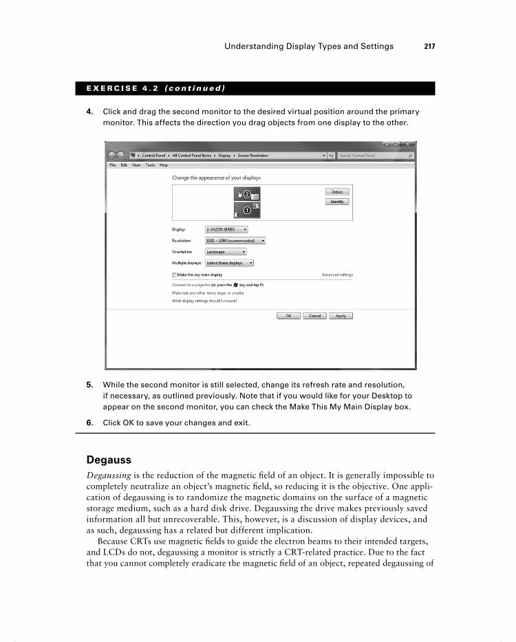
4. Click and drag the second monitor to the desired virtual position around the primary monitor. This affects the direction you drag objects from one display to the other.
5. While the second monitor is still selected, change its refresh rate and resolution, if necessary, as outlined previously. Note that if you would like for your Desktop to appear on the second monitor, you can check the Make This My Main Display box.
6. Click OK to save your changes and exit.
Degauss
Degaussing is the reduction of the magnetic fi eld of an object. It is generally impossible to completely neutralize an object’s magnetic fi eld, so reducing it is the objective. One appli-cation of degaussing is to randomize the magnetic domains on the surface of a magnetic storage medium, such as a hard disk drive. Degaussing the drive makes previously saved information all but unrecoverable. This, however, is a discussion of display devices, and as such, degaussing has a related but different implication.
Because CRTs use magnetic fi elds to guide the electron beams to their intended targets, and LCDs do not, degaussing a monitor is strictly a CRT-related practice. Due to the fact that you cannot completely eradicate the magnetic fi eld of an object, repeated degaussing of
324059c04.indd 217324059c04.indd 217 8/17/12 9:20 AM8/17/12 9:20 AM

218 Chapter 4 � Display Devices
a CRT monitor is not advised. In fact, the monitor can be damaged by degaussing it more than once in a short period of time.
The constant bombardment of the metallic shadow mask of a CRT monitor by the electron beams can cause magnetic fi elds to build up on the mask. These fi elds affect the paths of the electrons, resulting in distortions that manifest themselves as image discolor-ation and rainbow effects. Many later-generation CRTs have an internal degaussing coil wrapped around the front portion of the unit near the shadow mask. Newer CRTs activate the coil each time the unit is turned on with the power button, resulting in a sometimes dramatic, humming noise of extremely short duration whenever power is applied. These monitors rarely require intentional manual degaussing by the user or technician as a result.
When these internal degaussing coils are activated manually by a button on the monitor or through the monitor’s internal menu system, the same noise can be heard. Additionally, because the monitor is already powered up and displaying an image, you will notice the image shaking at the same time. Unadvised, repeated coil activation results in increasingly less dramatic results with each iteration.
External degaussing devices exist that reduce the magnetic fi eld in the shadow mask. Because these tools can be made considerably stronger than the space-restricted internal coils, they can at once be more effective and more damaging to the sensitive magnetic yokes that guide the electron beams. Excessive electromagnetic energy has been known to permanently damage CRTs. You should take great care when using external degaussing devices on CRTs.
Some monitors have a degaussing button right on the front panel. The CRT used in Exercise 4.3 requires that you degauss from an onscreen menu system that is independent of the operating system. Nevertheless, if this monitor does not detect an attached system, it will not let you into the menu. Exercise 4.3 guides you through using the built-in degauss-ing feature of a Dell M781 monitor.
E X E RC I S E 4 . 3
Degaussing a CRT Monitor
1. Attach the CRT to a working computer system and power on the monitor.
2. Press the Menu button on the front panel of the CRT cabinet (the button on the far right in the following photo).
324059c04.indd 218324059c04.indd 218 8/17/12 9:20 AM8/17/12 9:20 AM

Understanding Display Types and Settings 219
E X E R C I S E 4 . 3 ( c ont inue d )
The following screen shot shows the resulting menu. Notice that the monitor detects the signal it is receiving from the graphics adapter. In this case, a resolution of 1600 n 1200 (UXGA—see Table 4.1 later in this chapter) and a refresh rate of 60Hz are detected. This monitor even offers advice on the recommended resolution for best results. In this case, 1024 n 768 is recommended. When the recommendation is followed, a better fi t to the dot phosphors and a wider selection of refresh rates are likely.
3. Use the up- and down-arrow keys on the front panel of the CRT to select the Extra Controls menu item.
4. Press the Menu button on the front panel to select the Extra Controls submenu, shown here.
324059c04.indd 219324059c04.indd 219 8/17/12 9:20 AM8/17/12 9:20 AM

220 Chapter 4 � Display Devices
E X E R C I S E 4 . 3 ( c ont inue d )
5. Press the Menu button on the front panel of the CRT because the Degauss menu item is already selected. If degaussing was required, you should hear the distinctive degaussing noise and notice the image distorting as shown here.
Understanding Video Standards and Technologies The following sections introduce the various video standards, from the earlier digital stan-dards to the later analog standards and the most current digital high-defi nition standards.
Pre-VGA standards are presented here to give perspective regarding dis-play technology as a whole. Do not expect to be tested on any standards prior to VGA.
Video Standards
The early video standards differ in two major areas: the highest resolution supported and the maximum number of colors in their palette. The supported resolution and palette size are directly related to the amount of memory on the adapter, which is used to hold the ren-dered images to be displayed. Display adapters through the years can be divided into fi ve primary groups:
� Monochrome
� CGA
324059c04.indd 220324059c04.indd 220 8/17/12 9:20 AM8/17/12 9:20 AM

Understanding Video Standards and Technologies 221
� EGA
� VGA
� DVI, HDMI, and other modern digital video
See Chapter 3, “Peripherals and Expansion,” for more information on DVI, HDMI, and other advanced video standards.
Because the amount of memory used to implement the pre-VGA adapters was fi xed, the resolution and number of colors supported by these cards was fi xed as well. Newer standards, based on VGA analog technology and connectivity, were eventually developed using adapters with expandable memory or separately priced models with differing fi xed memory. Adapters featuring variable amounts of memory resulted in selectable resolutions and color palettes. In time, 24-bit color palettes known as Truecolor and made up of almost 17 million colors, which approached the number of colors the human eye can distinguish, were implemented. As a result, in keeping with growing screen sizes, the latest commercial video standards continue to grow in resolution, their distinguishing trait, but generally not in palette size. These post-VGA resolutions are discussed later in this chapter in the section “Advanced Video Resolutions and Concepts.”
Monochrome
The fi rst video technology for PCs was monochrome (from the Latin mono , meaning one, and chroma , meaning color). This black-and-white video (actually, it was green or amber text on a black background) was fi ne for the main operating system of the day, DOS. DOS didn’t have any need for color. Thus, the video adapter was very basic. The fi rst adapter, developed by IBM, was known as the Monochrome Display Adapter (MDA). It could dis-play text but not graphics and used a resolution of 720 n 350 pixels.
The Hercules Graphics Card (HGC), introduced by Hercules Computer Technology, had a resolution of 720 n 350 and could display graphics as well as text. It did this by using two separate modes: a text mode that allowed the adapter to optimize its resources for display-ing predrawn characters from its onboard library and a graphics mode that optimized the adapter for drawing individual pixels for onscreen graphics. It could switch between these modes on the fl y. These modes of operation have been included in all graphics adapters since the introduction of the HGC.
CGA
The next logical step for displays was to add a splash of color. IBM was the fi rst with color, with the introduction of the Color Graphics Adapter ( CGA ). CGA displays 16-color text in resolutions of 320 n 200 (40 columns) and 640 n 200 (80 columns), but it displays 320 n 200 graphics with only four colors per mode. Each of the six possible modes has 3 fi xed colors and a selectable 4th; each of the 4 colors comes from the 16 used for text. CGA’s 640 n 200 graphics resolution has only 2 colors—black and one other color from the same palette of 16.
324059c04.indd 221324059c04.indd 221 8/17/12 9:20 AM8/17/12 9:20 AM

222 Chapter 4 � Display Devices
EGA
After a time, people wanted more colors and higher resolution, so IBM responded with the Enhanced Graphics Adapter ( EGA ). EGA could display 16 colors out of a palette of 64 with CGA resolutions as well as a high-resolution 640 n 350 mode. EGA marks the end of classic digital-video technology. The digital data pins on the 9-pin D-subminiature connector accounted for six of the nine pins. As a solution, analog technologies, starting with VGA, would all but stand alone in the market until the advent of DVI and HDMI, discussed in Chapter 3.
VGA
With the PS/2 line of computers, IBM wanted to answer the cry for “more resolution, more colors” by introducing its best video adapter to date: the Video Graphics Array ( VGA ). This video technology had a “whopping” 256KB of video memory on board and could display 16 colors at 640 n 480, 640 n 350, and 320 n 200 pixels or, using mode 13h of the VGA BIOS, 256 colors at 320 n 200 pixels. It became widely used and enjoyed a long reign as at least the base standard for color PC video. For many years, it was the starting point for computers, as far as video is concerned. Until recently, however, your computer likely defaulted to this video technology’s resolution and color palette only when there was an issue with the driver for your graphics adapter or when you entered Safe Mode. Today, even these modes display with impressive graphics quality.
One unique feature of VGA (and its offshoots) is that it’s an analog technology, unlike the preceding and subsequent standards. Technically, the electronics of all graphics adapters and monitors operate in the digital realm. The difference in VGA-based technologies is that graphics adapters output and monitors receive an analog signal over the cable. Conversely, MDA, CGA, EGA, HDMI, and DVI-D signals arrive at the monitor as digital pulse streams with no analog-to-digital conversion required.
VGA builds a dynamic palette of 256 colors, which are chosen from various shades and hues of an 18-bit palette of 262,114 colors. When only 16 colors are displayed, they are chosen from the 256 selected colors. VGA sold well mainly because users could choose from almost any color they wanted (or at least one that was close). The reason for moving away from the original digital signal is because for every power of 2 that the number of col-ors in the palette increases, you need at least one more pin on the connector. A minimum of 4 pins for 16 colors is not a big deal, but a minimum of 32 pins for 32-bit graphics become a bit unwieldy. The cable has to grow with the connector, as well, affecting transmission quality and cable length. VGA, on the other hand, requires only 3 pins, one each for red, green, and blue modulated analog color levels, not including the necessary complement of ground, sync, and other control signals. For this application, 12 to 14 of the 15 pins of a VGA connector are adequate.
One note about monitors that may seem rather obvious: You must use a video card that supports the type of monitor you are using. For example, you can’t use a CGA monitor on a VGA adapter. Add-on adapters must also have a matching slot in the motherboard to accom-modate them.
324059c04.indd 222324059c04.indd 222 8/17/12 9:20 AM8/17/12 9:20 AM
Understanding Video Standards and Technologies 223
Advanced Video Resolutions and Concepts
The foregoing display technologies included hardware considerations and resolutions. Adjustments could be made to change the confi guration of these technologies. Additional resolutions common in the computing world through the years and characteristics that cannot be adjusted but instead defi ne the quality of the display device are presented in the following sections.
Resolutions
The following sections detail what might, at fi rst, appear to be technologies based on new graphics adapters. However, advancements after the VGA adapter occurred only in the mem-ory and fi rmware of the adapter, not the connector or its fundamental analog functionality. As a result, the following technologies are distinguished early on by supported resolutions and color palettes and later by resolutions alone. Subsequently, these resolutions have become supported by the newer digital standards with no change in their friendly names.
Super VGA
Up until the late 1980s, IBM set most personal-computer video standards. IBM made the adapters, everyone bought them, and they became a standard. Some manufacturers didn’t like this monopoly and set up the Video Electronics Standards Association (VESA) to try to enhance IBM’s video technology and make the enhanced technology an open standard. The initial result of this work was Super VGA ( SVGA ). This new standard was indeed an enhancement because it could support 16 colors at a resolution of 800 n 600 (the VESA standard), but it soon expanded to support 1024 n 768 pixels with 256 colors.
Since that time, SVGA has been a term used loosely for any resolution and color palette to exceed that of standard VGA. This even includes the resolution presented next, XGA. New names still continue to be introduced, mainly as a marketing tool to tout the new resolution du jour. While display devices must be manufactured to support a certain display resolution, one of the benefi ts of analog video technology was that later VGA monitors could advance along with the graphics adapter, in terms of the color palette. The analog signal is what dictates the color palette, and the standard for the signal has not changed since its VGA origin. This makes VGA monitors’ color limitations a nonissue. Such a topic makes sense only in reference to graphics adapters.
XGA
IBM introduced a new technology in 1990 known as the Extended Graphics Array ( XGA ). This technology was available only as a Micro Channel Architecture (MCA) expansion board (vs. ISA or EISA, for instance). XGA could support 256 colors at 1024 n 768 pixels or 65,536 colors at 800 n 600 pixels. It was a different design, optimized for GUIs of the day such as Windows or OS/2. It was also an interlaced technology when operating at the 1024 n 768 resolution, meaning that rather than scan every line one at a time on each pass to create the image, it scanned every other line on each pass, using the phenomenon known as “ p ersistence of vision ” to produce what appears to our eyes as a continuous image.
324059c04.indd 223324059c04.indd 223 8/17/12 9:20 AM8/17/12 9:20 AM

224 Chapter 4 � Display Devices
The i in 1080i refers to interlaced—vs. progressive ( 1080p ) scanning.
The advertised refresh rate specifi es the frequency with which all odd or all even rows are scanned. The drawback to interlacing is that the refresh rate used on a CRT has to be twice the minimum comfort level for refreshing an entire screen. Otherwise, the human eye will interpret the uncomfortably noticeable decay of the pixels as fl icker. Therefore, a refresh rate of 120Hz would result in a comfortable effective refresh rate of 60Hz. Unfortunately, 84Hz was a popular refresh rate for interlaced display signals, resulting in an entire screen being redrawn only 42 times per second, a rate below the minimum comfort level.
More Recent Video Standards
Any standard other than the ones already mentioned are probably extensions of SVGA or XGA. It has becoming quite easy to predict the approximate or exact resolution of a video specifi cation based on its name. Whenever a known technology is preceded by the letter W , you can assume roughly the same vertical resolution but a wider horizontal resolution to accommodate 16:10 wide-screen formats (16:9 for LCD and plasma televisions). Preceding the technology with the letter Q indicates that the horizontal and vertical resolutions were each doubled, making a fi nal number of pixels 4 times (quadruple) the original. To imply 4 times each, for a fi nal resolution enhancement of 16 times, the letter H for hexadecatuple is used.
Therefore, if XGA has a resolution of 1024 n 768, then QXGA will have a resolution of 2048 n 1536. If Ultra XGA (UXGA) has a resolution of 1600 n 1200 and an aspect ratio of 4:3, then WUXGA has a resolution of 1920 n 1200 and a 16:10 aspect ratio. Clearly, there have been a large number of seemingly minute increases in resolution column and row sizes. However, consider that at 1024 n 768, for instance, the screen will display a total of 786,432 pixels. At 1280 n 1024, comparatively, the number of pixels increases to 1,310,720—nearly double the pixels for what doesn’t sound like much of a difference. As mentioned, you need better technology and more video memory to display even slightly higher resolutions.
The term aspect ratio refers to the relationship between the horizontal and vertical pixel counts that a monitor can display. For example, for a display that supports 4:3 ratios, such as 1024 n 768, if you divide the first number by 4 and multiply the result by 3, the product is equal to the second number. Additionally, if you divide the first number by the second number, the result is approximately 1.3, the same as 4 - 3. Displays with a 16:10 aspect ratio have measurements that result in a dividend of 16 - 10 = 1.6.
Table 4.1 lists the various video technologies, their resolutions, and the maximum color palette they support, if specifi ed as part of the standard. All resolutions, VGA and higher, have a 4:3 aspect ratio unless otherwise noted.
324059c04.indd 224324059c04.indd 224 8/17/12 9:20 AM8/17/12 9:20 AM

Understanding Video Standards and Technologies 225
TA B LE 4 .1 Video display technology comparison
Name Resolutions Colors
Monochrome Display Adapter (MDA) 720 n 350 Mono (text only)
Hercules Graphics Card (HGC) 720 n 350 Mono (text and graphics)
Color Graphics Adapter (CGA) 320 n 200 4
640 n 200 2
Enhanced Graphics Adapter (EGA) 640 n 350 16
Video Graphics Array (VGA) 640 n 480 16
320 n 200 256
ATSC 480i/480p, 4:3 or 16:9 704 n 480 Not specified
Super VGA (SVGA) 800 n 600 16
Extended Graphics Array (XGA) 800 n 600 65,536
1024 n 768 256
Widescreen XGA (WXGA), 16:10 1280 n 800 Not specified
Super XGA (SXGA), 5:4 1280 n 1024 Not specified
ATSC 720p, 16:9 1280 n 720 Not specified
SXGA+ 1400 n 1050 Not specified
WSXGA+, 16:10 1680 n 1050 Not specified
Ultra XGA (UXGA) 1600 n 1200 Not specified
WUXGA, 16:10 1920 n 1200 Not specified
ATSC 1080i/1080p, 16:9 1920 n 1080 Not specified
Quad XGA (QXGA) 2048 n 1536 Not specified
WQXGA, 16:10 2560 n 1600 Not specified
324059c04.indd 225324059c04.indd 225 8/17/12 9:20 AM8/17/12 9:20 AM

226 Chapter 4 � Display Devices
Name Resolutions Colors
WQUXGA, 16:10 3840 n 2400 Not specified
WHUXGA, 16:10 7680 n 4800 Not specified
Starting with SXGA, the more advanced resolutions can be paired with 32-bit graphics, which specifi es the 24-bit Truecolor palette of 16,777,216 colors and uses the other 8 bits for enhanced noncolor features, if at all. In some cases, using 32 bits to store 24 bits of color information per pixel increases performance because the bit boundaries are divisible by a power of 2; 32 is a power of 2, but 24 is not. That being said, however, unlike with the older standards, the color palette is not offi cially part of the newer specifi cations.
Nonadjustable Characteristics
The following sections discuss features that are more selling points for display units and not confi gurable settings.
Native Resolution
One of the peculiarities of LCD, plasma, OLED, and other fl at-panel displays is that they have a single fi xed resolution, known as the native resolution . Unlike CRT monitors, which can display a crisp image at many resolutions within a supported range, fl at-panel monitors have trouble displaying most resolutions other than their native resolution.
The native resolution comes from the placement of the transistors in the hardware display matrix of the monitor. For a native resolution of 1680 n 1050, for example, there are 1,764,000 transistors (LCDs) or cells (PDPs and OLED displays) arranged in a grid of 1680 columns and 1050 rows. Trying to display a resolution other than 1680 n 1050 through the operating system tends to result in the monitor interpolating the resolution to fi t the differing number of software pixels to the 1,764,000 transistors, often result-ing in a distortion of the image on the screen.
The distortion can take various forms, such as blurred text, elliptical circles, and so forth. SXGA (1280 n 1024) was once one of the most popular native resolutions for larger LCD computer monitors before use of wide-screen monitors became pervasive. For wide-screen aspects, especially for wide-screen LCD displays of 15.4 g and larger, WSXGA+ (1680 n 1050) was one of the original popular native resolutions. The ATSC 1080p resolu-tion (1920 n 1080) is highly common today across all display technologies, largely replacing the popular computer-graphics version, WUXGA (1920 n 1200).
Contrast Ratio
The contrast ratio is the measure of the ratio of the luminance of the brightest color to that of the darkest color the screen is capable of producing. Do not confuse contrast ratio with
TA B LE 4 .1 Video display technology comparison (continued)
324059c04.indd 226324059c04.indd 226 8/17/12 9:20 AM8/17/12 9:20 AM
Understanding Video Standards and Technologies 227
contrast . Contrast ratios are generally fi xed measurements that become selling points for the monitors. Contrast, on the other hand, is an adjustable setting on all monitors (usually found alongside brightness) that changes the relative brightness of adjacent pixels. The more con-trast, the sharper and edgier the image. Reducing the contrast too much can make the image appear washed out. This discussion is not about contrast but instead contrast ratio.
One of the original problems with LCD displays, and a continuing problem with cheaper versions, is that they have low contrast ratios. Only LED-backlit LCD panels rival the high contrast ratios that plasma displays have always demonstrated. A display with a low contrast ratio won’t show a “true black” very well, and the other colors will look washed out when you have a light source nearby. Try to use the device in full sunshine and you’re not going to see much of anything, although the overall brightness level is the true key in such surround-ings. Also, lower contrast ratios mean that you’ll have a harder time viewing images from the side as compared with being directly in front of the display.
Ratios for smaller LCD monitors and televisions typically start out around 500:1. Common ratios for larger units range from 20,000:1 to 100,000:1. In the early days of monitors that used LEDs as backlights, 1,000,000:1 was exceedingly common. Today, vendors advertise 10,000,000:1 and “infi nite” as contrast ratios. Anything higher than 32,000:1 is likely a dynamic contrast ratio. Plasma displays have always been expected to have contrast ratios of around 5,000:1 or better.
Once considered a caveat, a dynamic ratio is realized by reducing power to the back-light for darker images. The downside was that the original backlight being a single fl uorescent bulb meant that the signal to the brighter LCD pixels had to be amplifi ed to compensate for the uniform dimming of the backlight. This occasionally resulted in over-compensation manifested as areas of extreme brightness, often artifi cial in appearance. This practice tends to wash out the lighter colors and make white seem like it’s glowing, which is hardly useful to the user. Today’s LED backlights, however, are controlled either in zones made up of a small number of pixels or individually per pixel, resulting in trust-worthy high dynamic contrast ratios.
The environment where the monitor will be used must be taken into account when consid-ering whether to place a lot of emphasis on contrast ratio. In darker areas, a high contrast ratio will be more noticeable. In brighter surroundings, widely varying contrast ratios do not make as much of a difference. For these environments, a monitor capable of higher levels of bright-ness is more imperative.
One caveat to contrast ratios that remains is that there is no vendor-neutral regulatory measurement. The contrast ratio claimed by one manufacturer can take into account vari-ables that another manufacturer does not. A manufacturer can boost the ratio simply by increasing how bright the monitor can go, the portion of the monitor tested, or the conditions in the room where the test was performed. This doesn’t do anything to help the display of darker colors, though. So, although the contrast ratio is certainly a selling point, don’t just take it at face value. Look for independent comparison reviews that use multiple methods of measuring contrast ratio or compare displays in person to see which one works better for the situation in which you intend to use it.
324059c04.indd 227324059c04.indd 227 8/17/12 9:20 AM8/17/12 9:20 AM

228 Chapter 4 � Display Devices
Summary In this chapter, you read about various display technologies and settings. The primary catego-ries of video display unit were mentioned and explained: CRT, LCD, LED, OLED, plasma, and projector. Concepts unique to each of these categories were explored. Additionally, the similarities among them were highlighted. We identifi ed names and characteristics of display resolutions and explained the process of confi guring settings such as resolution, refresh rate, and multimonitor support in Windows.
Exam Essentials
Be able to compare and contrast the main categories of display technology. Although video display units all have roughly the same purpose—to display images created by the computer and rendered by the graphics adapter—CRTs, LCDs, LEDs, plasmas, OLEDs, and projectors go about the task in slightly different ways.
Be familiar with the key terms and concepts of display units. Make sure you can differ-entiate among terms such as resolution , refresh rate , and brightness , and be familiar with terms used in other settings that might be found on the monitor or in the operating system.
Understand key concepts behind LCD and other flat-panel technology. You need to be familiar with active and passive matrix; resolution standards, such as XGA and UXGA; and terms such as contrast ratio and native resolution .
Familiarize yourself with the steps that must be taken to configure display settings in Windows. Most of the settings based on the operating system are found in roughly the same place. However, nuances found in the details of confi guring these settings make it important for you to familiarize yourself with the specifi c confi guration procedures.
324059c04.indd 228324059c04.indd 228 8/17/12 9:20 AM8/17/12 9:20 AM