cfr final rule - lessons learnedlessonslearned.faa.gov/ona32/cfr_aircraft_wheels.pdf · wheels and...
TRANSCRIPT
CFR Final Rule
Federal Register Information
[Federal Register: November 29, 1979 (Volume 44, number 231)] [Page 68738]
Header Information DEPARTMENT OF TRANSPORTATION Federal Aviation Administration 14 CFR Parts 23 and 25 [Docket No. 18564; Amendment Nos. 23-24, 25-48] Aircraft Wheels and Wheel-Brake Assemblies; Airworthiness and Performance Standards
Preamble Information AGENCY: Federal Aviation Administration, DOT ACTION: Final Rule 14 CFR Parts 23, 25 and 37 Amendment Nos. 23-24; 25-48; and 37-45 SUMMARY: The purpose of this amendment is to revise the Technical standard Order (TSO) for aircraft wheels and wheel-brake assemblies and related type certification requirements for airplane brakes. As revised, the standards will incorporate updated and improved minimum performance standards for the design and construction of aircraft wheels and brakes. EFFECTIVE DATE: December 31, 1979. FOR FURTHER INFORMATION CONTACT: Mr. Raymond E. Ramakis, Regulatory Projects Branch, AVS-24, Safety Regulations Staff, Associate Administrator for Aviation Standards, Federal Aviation Administration, 800 Independence Avenue, SW., Washington, D.C. 20591; telephone (202) 755-8716. SUPPLEMENTARY INFORMATION: Background This amendment concerning aircraft wheels and wheel-brake assemblies is being issued concurrently with the amendment which updates the minimum performance standards applicable to aircraft tires. The preamble to the tires amendment (published also in this issue of the Federal Register) explains the background which has led to the need for revised standards for tires and for wheels and wheel-brake assemblies and their interrelation. The accidents and incidents affecting large commercial jet airplane involving landing gear have resulted in part from failures of tires and of wheels and brakes. With respect to
wheels and wheel-brake assemblies, failure due to fatigue is one of the more common and serious types of failures experienced with aircraft wheels. To improve the overall strength of wheels and to reduce their susceptibility to fatigue, the standards for wheels are being revised. These amendments will require more severe testing of wheels and wheel-brake assemblies to substantiate the load ratings of wheels and the kinetic energy capacity rating of brakes. These amendments are based on a Notice of Proposed Rule Making, Notice No. 78-16, published in the Federal Register on December 7, 1978 (43 FR 57281). That notice invited comments by all interested persons. All persons have been afforded an opportunity to participate in the making of these amendments and due consideration has been given to all matter presented. Significant comments received in response to Notice 78-16 are discussed below. A number of substantive, editorial, and clarifying changes have been made to the proposed rules based on relevant comments received and on further review within the FAA. Except for minor editorial and clarifying changes and those discussed below, these amendments and the reasons for their adoption are the same as those contained in Notice 78-16. This amendment implements the President's directive (Executive Order 12044) that regulations be as simple as possible and not impose unnecessary burdens on the economy or on the regulated public. The amendment also promotes the public interest by increasing safety and the efficiency of aircraft through use of improved wheels and wheel-brake assemblies. Discussion of General Comments Fifteen commenters, including seven non-U.S. organizations, responded to Notice 78-16 with 64 comments. The majority of the comments presented the views of manufacturers and air carriers. In general, the commenters concerned themselves with those areas of the proposal they believe could be improved and raised no objection to the basic concept of the proposal. There were several favorable comments received in support of the proposal and one commenter stated that the proposed revision of the TSO is a significant improvement over the existing TSO. Two commenters recommended that it should be demonstrated by test that the wheel flanges be able to withstand concentrated loads and not come apart under the condition of deflated or missing tires. There should be a specific test requirement which assures that a wheel will maintain its integrity with the loss of a mated tire. A new paragraph 4.1(c)(3) is added for this purpose. Discussion of Specific Comments Sec. 23.735 Brakes. A commenter suggested the numerical constant in the formula for calculating kinetic
energy would be more accurate if written as 0.0443 in place of 0.0442 in Sec. 23.735(a)(2) of the Federal Aviation Regulations (FAR). This change is adopted. Sec. 25.735 Brakes. As pointed out by three commenters, Sec. 25.75, which prescribes landing requirements for reciprocating engine powered transport category airplanes, was deleted by a recent amendment and should no longer be referred to in the rule. The reference to Sec. 25.75 is replaced by a reference to Sec. 25.125 which prescribes the landing requirements for all transport category airplanes. Two commenters suggested that the numerical constant in the formula for calculating the kinetic energy requirements for each main wheel brake assembly should be 0.0443. The change is incorporated. Three commenters recommended that "N", as it is used in the formula in Sec. 25.735(f)(2), should be further defined as "the number of wheels with brakes" to be consistent with the TSO. The comment is valid. However, the word "main" must be a part of the definition because Sec. 25.735(f) applies to the brakes on main wheels only. This aspect applies equally to the formula and definition in Sec. 23.735(a)(2). The definitions of "N" in Secs. 23.735(a)(2) and 25.735(f)(2) are amended accordingly. Three commenters recommended that a reference to the accelerate-stop case should be made in Sec. 25.735(f)(2). However, the requirements in that paragraph are for kinetic energy absorption requirements for brake assemblies in normal operations. The provisions for the accelerate-stop distance determination are set forth in Secs. 25.105 and 25.109 which concern other performance requirements involved in emergency situations and which are not appropriate for Sec. 25.735(f)(2). Two commenters suggested that the words "wheel-brake assembly" as they appear in Sec. 25.735(f) and (g) should be changed to "wheel tire and brake assembly". However, tire requirements are covered in Sec. 25.733 and experience has not indicated a need for the recommended change. Sec. 37.172 Aircraft Wheels and Wheel-Brake Assemblies - TSO-C26C Sec. 37.172(b) Marking. A commenter suggested that the date of manufacture should always be shown on the wheel and brake assemblies. However, no reason was given. The requirement is to mark the serial number or date of manufacture or both. The marking requirements are the minimums necessary for identification of the article by the FAA. If the manufacturer elects to mark the article with the serial number alone, the FAA may obtain the date of manufacture from factory production records when needed. Therefore, it is not necessary that the date of manufacturer be shown in all cases in order to adequately identify a wheel or wheel brake assembly.
One commenter recommended that tire change counters be included on the wheel and some external marking be placed on the wheel rim to indicate the position of drive keys to facilitate alignment with rotors on the brake heat sink. While tire change counters and alignment markings may be useful to maintenance personnel, they do not represent a safety consideration and should not be imposed as wheel and brake requirements. The customer may contract with the manufacturer to have these items marked on the wheel if desired. Sec. 37.172(c) Data Requirements. A commenter recommended that "stop distance" and "average deceleration" be added as required data and also be added in paragraphs 4.2(a)(2) of the TSO where the average deceleration would be defined as equaling the square of the brakes on velocity (V?) divided by twice the stop distance(s). As an alternative to adding the stop distance, it was recommended that the stop distance be equal to or less than the square of the brakes on velocity divided by twice the average deceleration. The TSO establishes the minimum performance required of wheel and brakes. The manufacturer has the option of exceeding the requirements if it wishes. An aircraft or brake manufacturer may use the method recommended but should not be required to do so. Sec. 37.172(d) Previously Approved Equipment. A commenter recommended a change in the rules to allow a manufacturer to complete its contractual obligations under the TSO requirements in effect at the time of the contract or a 2-year extension beyond the effective date of the new TSO. The problem is the long lead time required to design, build, and test certain types of equipment during which time the TSO may be changed. While this is not unique to wheels and brakes, in some cases a wheel/brake assembly, not yet approved, may be required to meet additional safety provisions contained under the new TSO. However, the rule does not negate any approvals given under the earlier TSO nor does it prohibit production of items under earlier approvals. This commenter also contended that the new wheel and brake standards will result in increased costs to manufacturers, particularly for transport category airplanes. While some additional costs may be incurred initially because of the extra testing involved, the added safety resulting from fewer wheel failures and less damage to operating aircraft caused by wheel and brake failures will more than outweigh such costs. Standard for Wheels and Wheel-Brake Assemblies. Paragraph 2(a)(1) Lubricant Retainers. A commenter suggested that the design criteria in the paragraph may be good for wheels but not necessarily applicable for the brake chassis. It contended that if grease retaining is used in the brake chassis, inadequate lubrication results, giving rise to excessive wear and
bearing defects. However, there is no service history problem related to lubricant retainers on brake chassis and the commenter offered no supporting data for the suggestion. The paragraph is adopted as proposed. Paragraph 2(a)(3) Adjustment. A commenter recommended that a requirement be added to specify that all brake units be fitted with pressure plate pull-off devices to ensure minimum running clearance when brakes are in the off position. It was asserted that the requirement would assist in reducing heat build-up during taxiing. The commenter did not justify the need for such a requirement. A brake designer is not prohibited from incorporating pressure plate pull-off devices if they are desired. However, no purpose would be served in listing the various brake design features such as pressure plate pull-off devices that may be desirable from an operations or maintenance viewpoint but are not necessary for safety. Paragraph 2(a)(5) Explosion Prevention. A commenter suggested that more attention should be given to establishing the correct siting, number, and size of fuses. The commenter also cautioned that provision of too many fuses will increase the risk of running with under-inflated tires. However, the commenter did not recommend any changes or allege that the standard is inadequate. There is no service history to indicate problems with fuse plug selection. The current rule is adequate and is being continued in the new standard. Paragraph 2(a)(5) is adopted without change. Paragraph 2(b) Construction. A commenter stated that wheel failures are usually associated with fatigue or tire failure. The commenter noted that protection against fatigue failure is not adequately reflected in the standard and suggested that fatigue resistance enhancement measures (such as shot peening, cold rolling, etc.) could be required in fatigue critical areas. As suggested, there should be a specific requirement to improve the fatigue resistance of the wheel and a new Sec. 2(b)(11) is added for this purpose. A commenter suggested that heavy emphasis should be placed on standardization with respect to the hub and bead, seat areas, and the need for protection of aluminum alloy parts. The commenter asserted that in-service corrosion is a frequent cause of rim failures. Although possible cost benefits to manufacturers and operators may result from standardization of wheel and brake designs, such an option is open without the rules requiring it. Moreover, standardization imposed by the rules could inhibit new designs. With respect to the comments regarding the hub and bead seat areas and protection of aluminum alloy parts, requirements for these areas are adequately covered in paragraphs 2(b)(1) and 2(b)(2). No change is made to the proposal based in these comments. Paragraph 2(b)(6) Bolts and Studs.
A commenter stated that during removal of wheel tie bolts, it has been common experience to find there is insufficient clearance between the socket and wheel surface using standard sockets. Further, if tools are worn, it is necessary to use an inserted protective surface to prevent wheel or brake damage. These comments relate to individual design considerations which may in some cases require special tools. They do not provide a basis for changing the standard. Paragraph 2(b)(7) Steel Parts. A commenter recommended that paragraph 2(b)(7) include words limiting the use of cadmium plating on parts operating at temperatures above the melting point of cadmium. The comment has merit. Although cadmium and zinc plating have been satisfactory in protecting wheel and brake components against corrosion in the past, the TSO should not limit corrosion protection methods to cadmium and zinc plating. There may be other equivalent or better protection methods, including methods better able to withstand temperature environments. Paragraph 2(b)(7) is revised to allow other corrosion protection means. Paragraph 2(b)(9) Magnesium Parts. A commenter suggested that the use of magnesium alloy parts be avoided in transport category aircraft wheel and wheel-brake assemblies. In the standard, the use of magnesium is optional. The designer may select another material depending on the intended use of the wheel and brake units. If magnesium alloy is used, then it must be given corrosion protection as specified. Paragraph 2(b)(10) Bearing and Braking Surfaces. A commenter pointed out that paragraph 2(b)(10) in TSO-C26b was not included in the proposal. The commenter asserted that although finish is not typically applied to assemblies, it is still appropriate to require protection of bearing and braking surfaces if a finish is to be applied. Clearly there is a need for the requirement. The paragraph was inadvertently omitted during the development of the proposal. Paragraph 2(b)(10) is incorporated in the adopted rule. Paragraph 3(a)(2) Rating. A commenter suggested adding the word "radial" to "maximum limit load" in paragraph 3(a)(2) to further qualify the meaning of the term. However, the word "radial" refers to direction and would be inappropriate for inclusion under this paragraph since the maximum limit load covers more than just radial loads. Paragraph 3(a)(2) is adopted as proposed. Paragraph 4.1 Wheel Tests.
A commenter recommended the test inflation pressure be increased up to a factor of 3.5 in place of the factor of 2 to avoid bottoming the tire while under the ultimate test load in paragraphs 4.1(a)(3) and 4.1(b)(3). The commenter contended that aircraft tires are operationally subject to test overpressures of 4 and 4.5 times their rated inflation pressure. The purpose of the ultimate load test is to load the wheel in a manner which is indicative of in-service conditions. Increasing the tire inflation pressure would provide an incorrect distribution of load on the wheel. Under the proposal, when tire bottoming occurs due to the application of ultimate test loads, provision is made for use of a loading block which fits between the rim flanges and simulates the load transfer of the tire. This test arrangement is satisfactory for determining yield and ultimate strengths of the wheel. No change is made based on this comment. Another commenter objected to allowing the tire pressure to be increased up to 2 times the rated inflation pressure to avoid tire bottoming during the ultimate load tests in paragraph 4.1(a)(3) and 4.1(b)(3). it was claimed that the test pressure allowed eliminates the only test condition that tests wheel flanges under concentrated loads. The commenter asserted that concentrated loads on the wheel flanges may occur when the wheel is rolling while the tire is deflated or missing. Finally, the commenter suggested that if the proposed test pressure is allowed, a separate test should be devised that demonstrates wheel flange strength. As previously discussed under General Comments there is sufficient justification to require a demonstration of flange strength based upon a missing tire, and a separate test is added under paragraph 4.1(c)(3). No other changes to paragraph 4.1(a)(3) or (b)(3) are necessary. A commenter contended that recent experience indicates there is a need for wheel tests with the brake unit installed. It was suggested that such tests be conducted under the test loads specified in proposed paragraph 4.1. In addition, the commenter recommended the tests include checks for adequate clearances between the wheel drive keys and brake rotor assembly while under test loading conditions. The commenter did not identify the experience and FAA records do not indicate any such problems in connection with past approvals of wheel and brake assemblies. Paragraph 4.1(a) is adopted without change. A commenter suggested that the ultimate test in paragraph 4.1(b)(3) be done with side loads applied in the most critical direction. However, such detailed specification is unnecessary since the direction, including inboard and outboard side directions, and magnitude of the test loads are established in accordance with the FAR sections referenced in the standard. A commenter pointed out that the use of the loading block specified in paragraph 4.1(b)(3) is incompatible with the statement in paragraph 4.1(b)(1). For clarification, the words "or the loading block" are added immediately after the word "tire" in the eighth sentence of paragraph 4.1(b)(1). Another commenter wanted the fit and loading position of the loading block to be more clearly defined. However, the paragraph prescribes the length of arc, the width and fit, and the load transfer characteristics of the block and therefore provides adequate information for use of the loading block.

A commenter contended that the yaw roll test of paragraph 4.1(c)(2) should be conducted with radial and side load components resulting from a 0.15g turn of the aircraft at the maximum weight and most adverse center of gravity location, as determined by the airframe manufacturer. Although the values of 0.15S and 0.15g are numerically equal, the side load component is more clearly defined as 0.15S rather than specifying a 0.15g turn condition as suggested by the commenter. Moreover, the maximum static load (S) is defined in terms of design takeoff weight and critical center of gravity as provided in Sec. 25.731(b), which is referenced in paragraph 3(a)(1). Another commenter understood that the intent of the proposed yaw roll test is to simulate a 0.15g turn condition and noted that the side load component is described as 0.15S in which S is a static load. The commenter did not distinguish the relationship of the terms 0.15g and 0.15S. There is no reason for wheel and brake manufactures to have difficulty in interpreting the meaning of 0.15S since the ground loads section of Part 25 designates side loads in terms of vertical ground reactions. No change is made based on these comments. A commenter suggested that "radial load" be changed to "vertical load" in paragraph 4.1(c). It is asserted that a vertical load would be perpendicular to the loading surface, whereas a radial load will have the same angular orientation as the wheel. However, in normal testing the orientation of the test wheel with respect to the loading surface may be such that applied loads are horizontal. In addition, the language is clear in the standard in requiring the radial load to be applied to the wheel through the axle and perpendicular to the load surface. The term "radial load", therefore, accurately expresses the intent. A commenter suggested that it should be made clear what rotational speed of the wheel is required in the roll test. Its experience is said to indicate that a good speed is about 10 miles per hour. However, the commenter did not provide any information to show that the standards should include a specified wheel test speed. Actually, although the roll performance of the wheel is not affected by roll speed, the roll speed must be selected to accommodate the operating characteristics of the installed tire. Under the proposal, the intent is that the applicant select any speed consistent with the tire characteristics. A commenter recommended that the wheel roll tests should include an overload test requirement. It has pointed out that in light of the 1.5 overload test factor for tires, wheel test criteria should at least match this requirement. It was alleged that wheels can be subjected to twice their normal rated load on more than one occasion during their service life. In this connection, however, significant improvements in wheel testing are being made in this standard over the wheel tests in the previous TSO and provide the equivalent of the overload test suggested by the commenter. An overload test for wheels is therefore not needed. A commenter pointed out that since a 7 percent safety margin was introduced for tires on transport category airplanes, it is advisable to include a 7 percent strength margin for wheels. It was suggested that one method of accomplishment would be to revise the overpressure factor from "4.0" to "4.07" in paragraph 4.1(d)(1). The comment, however, does not take into account that the overpressure factor for wheels is being increased 14 percent under paragraph 4.1(d)(1) which more than compensates for the 7 percent load
margin applied to main dual wheel tires. The comment offers no justification for increasing the overpressure factor above 14 percent. This increased factor, being adopted as proposed, provides the necessary strength margin. One commenter objected to the 4.0 overpressure factor in paragraph 4.1(d)(1), contending that the reasoning behind the increase from 3.5 to 4.0 was not understood. It was claimed that overinflation in service of this magnitude was highly unlikely and the 3.5 factor seemed acceptable. In recent years some air carriers have been operating with higher tire inflation pressures resulting in fewer tire-wheel-brake failures due to lower operating temperatures. The continued operation at higher inflation pressures requires stronger wheels to maintain their normal life expectancy. In addition, tire standards now include a higher overpressure factor (4.0) requirement for all types of tires. Thus, a compatible overpressure test for wheels is needed to establish a level of safety consistent with that of tires. No change is made based on this comment. Two comments supported the proposed 4.0 overpressure factor. One stated that the overpressure factor 4.0 should improve the strength of wheels. The other suggested that under conditions of high heat transfer, it should be demonstrated that the wheel is able to dissipate its pressure down to a residual level which will not cause bursting if wheel strength is impeded. However, such a requirement would inhibit design. The wheel and brake designer must account for critically high temperatures and pressures that may occur by installing adequate temperature and pressure-sensitive relief devices. Two commenters objected to the 5 percent maximum pressure drop from rated inflation pressure in a 24-hour period in the diffusion test requirement of paragraph 4.1(d)(2). They suggested the 5 percent be lowered and one recommended specifically that it be revised to 3 percent. The other supported the need for an overall leakage factor no greater than 5 percent and noted correctly that since the tire alone is allowed 5 percent, the leakage factor for the wheel would then have to be zero percent. The standard provides that the tire-wheel combination be subjected to the diffusion test for which the 5 percent pressure drop limit provides the required level of safety. The recommendation for a change to 3 percent was unsupported and the commenter provided no basis for going to a stricter limit. Therefore, no change is made based on these comments. Paragraph 4.2 Wheel-Brake Assembly Tests. Where a wheel, as part of a wheel-brake assembly, has previously been tested at a relatively high kinetic energy level, one commenter recommenced that when a different brake of lower kinetic energy is to be later used with the same wheel, only the brake should be required to be tested. The test is suggested, according to the commenter, because a given wheel model may be fitted with any brake assembly models. However, the test procedures recommended would not be in accord with Sec. 25.735(f) and proposed paragraph 4.2 which require wheel and brake units to be tested as assemblies. Under the commenter's proposal, the functional compatibility of the wheel and brake would be unknown since they would not have been tested as a unit. Therefore, no change is made to paragraph 4.2 based on this comment.

A commenter noted that paragraph 4.2 does not appear to require any kinetic energy margin to be built into the brake. That is correct; it is not necessary to require a specific safety margin if it can be demonstrated that the brakes are adequate for the purpose intended and can operate safely. The commenter also noted that the proposed tests allow credit for all brakes on an aircraft when there have been cases during rejected takeoffs where one or more tires have blown thereby rendering the corresponding brakes ineffective. However, the rationale is that wheels and brakes should not be unduly penalized by requiring over-design because tires may fail in operation. As pointed out previously, the FAA is upgrading aircraft tire standards to strengthen tires which will result in safer tire-wheel-brake combinations for the future. No change is made based on the comment. Three commenters suggested that the word "tyre" be included in the term "wheel-brake-assembly" in the proposed paragraph 4.2. It was stated that adding the word "tyre" would avoid the use of test tire which might absorb more than the correct share of kinetic energy. As suggested, the requirement should be clarified and the paragraph has been changed to specify inclusion of a suitable tire of proper fit. These commenters also recommended that the word "torque" be deleted from the title "Dynamic torque tests" in paragraph 4.2(a). However, the word is appropriately used in the standard since the intent is to measure torque accurately. These commenters further contended that where the energy absorbed by the tire can be satisfactorily established, an allowance for this should be made. However, this would effectively reduce the required kinetic energy ratings for wheel-brake assemblies and would be contrary to current safety needs to upgrade wheel and brake units. These commenters also asserted that the last sentence in paragraph 4.2(a)(1)(ii) about not considering decelerating effects of certain equipment is inconsistent with Sec. 25.125(b)(3). To the contrary, however, the language in the standard clarifies the test conditions by identifying those items whose decelerating effects are disallowed. Moreover, allowance of the proscribed deceleration effects in the qualification tests would reduce brake energy capacity ratings and would be contrary to the intent of the standard to upgrade wheel and brake standards. Two commenters pointed out that Method II in paragraph 4.2(a)(1)(ii) is allowed only for landing and recommended that it also be allowed for the accelerate-stop case. The first sentence of paragraph 4.2(a)(1)(ii) is amended accordingly. Paragraph 4.2(a)(2) Test Requirements. Two commenters suggested that the deceleration rates specified in Table II in paragraph 4.2(a)(2) be defined as equaling V2/2S, where V equals brakes on velocity and S equals the stop distance. They claimed that stop distance is the key parameter in determining

acceptability of the test results and that deceleration rate based on "time" will not necessarily result in an acceptable test. The comment is not accepted since the stop distance will vary between airplanes and can be established from the rate of deceleration as appropriate. A commenter recommended that for the products already approved by TSO-C26b, only 100 design landing stops should be required for the brake assembly, without the wheel, for certification under TSO-C26c. However, as discussed earlier in connection with kinetic energy considerations, a wheel and brake must be tested together to assure compatibility of performance. Four commenters recommended that the accelerate-stop test required in paragraph 4.2(a)(2) of the standard be conducted with brakes approaching the fully worn state. They maintain that the wearing elements of the brake assembly may be worn to a condition in which they are no longer capable of absorbing the maximum kinetic energy expected in service such as an accelerate-stop condition. However, in-service maintenance records do not indicate that there are failures associated with worn brakes not meeting rejected takeoff energy levels. Moreover, wear indicators on the brakes and required maintenance checks assure that brakes are replaced prior to the point at which they are no longer capable of absorbing the maximum kinetic energy. The commenters presented no evidence substantiating a need for such a test. A commenter suggested that the accelerate-stop deceleration rate in Table II selected by the manufacturer should be required to be equal to or greater than the deceleration required to produce the performance published in the Aircraft Flight Manual (AFM). However, no basis has been presented to relate requirements in the standard with the AFM as suggested by the commenter. The deceleration values used in certifying wheel-brake assemblies are selected by the manufacturer to obtain an estimated braking capability. The information in the AFM is related to actual aircraft flight test data. A commenter recommended that for the sake of safety, the accelerate-stop requirement in proposed Table II should be applicable to all aircraft. However, it is not practical to determine an accelerate-stop distance for a single engine airplane or any rotorcraft. Paragraph 4.2(a)(2) is adopted without change. Paragraph 4.2(a)(3) General Conditions. One commenter suggested that the following sentence be added to paragraph 4.2(a)(3)(ii): "Towards the end of the accelerate-stop test (KERT), it is permissible to release the brake when the inertia testing machine speed has reduced to not more than 10 knots". It claimed that for some brakes where the value of KERT is particularly high, it is possible for the friction elements to seize up at the end of the accelerate-stop thus preventing the brake from being unable for taxi. The suggestion would not be in accord with Sec. 25.109 which requires the airplane to come to a full stop during the accelerate-stop test.

A commenter suggested that the requirement for the brake to be usable for taxi after the accelerate-stop test be qualified by specifying taxi distance, taxi speed, and the number of additional brake applications expected following the deceleration. In view of present service experience there is no safety basis for requiring a brake to be usable after an accelerate-stop test. Accelerate-stop performance is currently predicted upon a condition of nonusable brakes and the allowance for subsequent maintenance prior to the removal of the airplane from the runway. Accordingly, paragraph 4.2(a)(3) is adopted as proposed. Paragraph 4.2(d) Endurance Tests - Hydraulic Brakes. A commenter pointed out that no consideration is given to the size of the brake equipment in the 5cc maximum leakage test in the standard. It asserted that since leakage varies with the size of the equipment, the 5cc limit appears to unjustly penalize large systems. This commenter recommended the proposed leakage rate be revised by allowing one drop per 25 cycles per 3-inch seal periphery. Another commenter asserted that it would consider its smallest brake a failure if it leaked 5cc. On the other hand, it was claimed that if its largest brake were to leak 5cc, it would consider the leakage minimal. This commenter suggested military standards be adopted, which in effect specify that after 25 cycles, (1) leakage at static seals not exceed a trace, and (2) leakage at moving seals not exceed one drop of fluid per each 3 inches of peripheral seal length. Although several methods of leakage measurements are available, the volumetric approach proposed in the notices gives a uniform standard and 5cc is acceptable for all sizes. Moreover, with reference to using words "trace" and "drop" as in the military standard, such terms do not define an identifiable and enforceable standard. The paragraph is adopted as proposed. Adoption of the Amendment Accordingly, Parts 23, 25, and 37 of the Federal Aviation regulations (14 CFR Parts 23, 25, and 37) are amended as follows, effective December 31, 1979.
Regulatory Information Part 23 - Airworthiness Standards: Normal, Utility, and Acrobatic Category Airplanes 1. By amending Sec. 23.735 by revising paragraph (a)(2) to read as follows: Sec. 23.735 Brakes. (a)* * * (2) Instead of a rational analysis, the kinetic energy absorption requirements for each main wheel brake assembly may be derived from the following formula: KE=0.0443 WV2/N where - KE=Kinetic energy per wheel (ft.-lb.); W=Design landing weight (lb.);
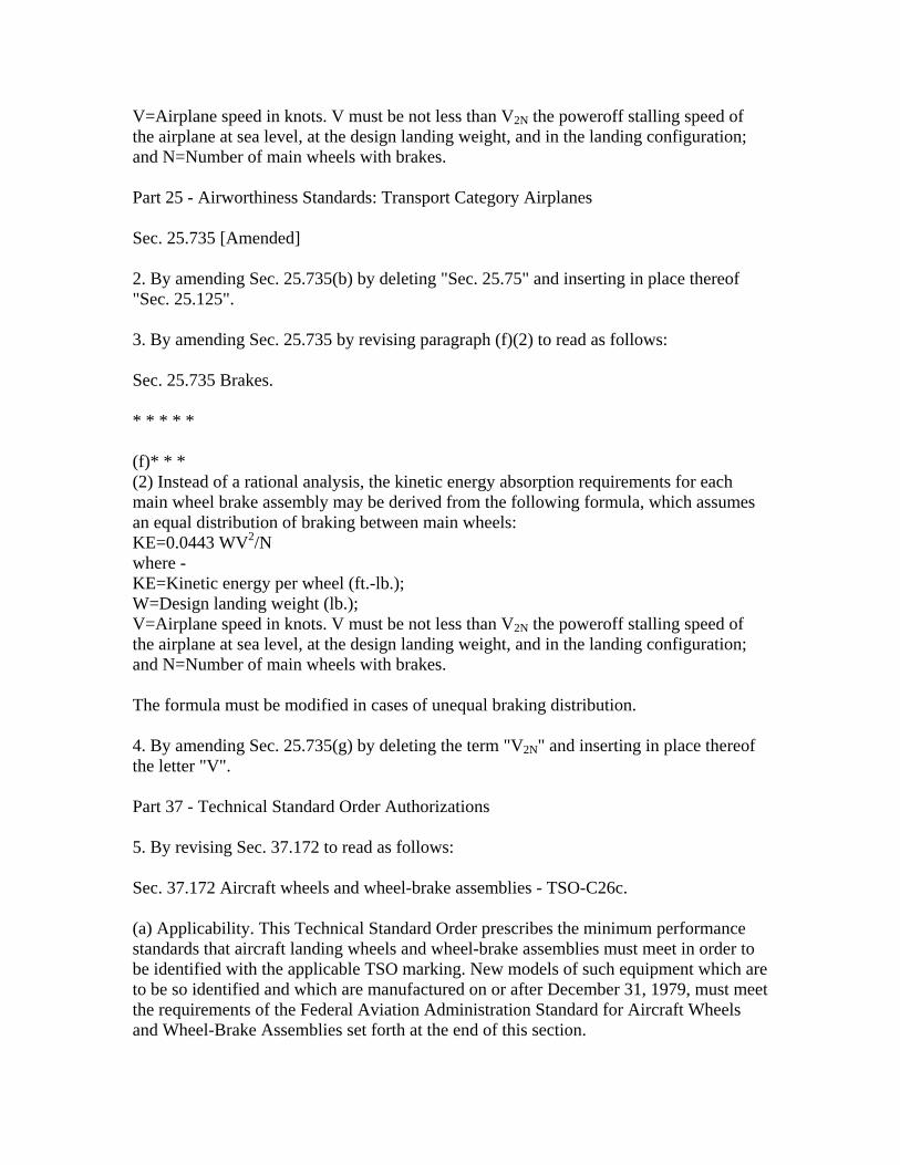
V=Airplane speed in knots. V must be not less than V2N the poweroff stalling speed of the airplane at sea level, at the design landing weight, and in the landing configuration; and N=Number of main wheels with brakes. Part 25 - Airworthiness Standards: Transport Category Airplanes Sec. 25.735 [Amended] 2. By amending Sec. 25.735(b) by deleting "Sec. 25.75" and inserting in place thereof "Sec. 25.125". 3. By amending Sec. 25.735 by revising paragraph (f)(2) to read as follows: Sec. 25.735 Brakes. * * * * * (f)* * * (2) Instead of a rational analysis, the kinetic energy absorption requirements for each main wheel brake assembly may be derived from the following formula, which assumes an equal distribution of braking between main wheels: KE=0.0443 WV2/N where - KE=Kinetic energy per wheel (ft.-lb.); W=Design landing weight (lb.); V=Airplane speed in knots. V must be not less than V2N the poweroff stalling speed of the airplane at sea level, at the design landing weight, and in the landing configuration; and N=Number of main wheels with brakes. The formula must be modified in cases of unequal braking distribution. 4. By amending Sec. 25.735(g) by deleting the term "V2N" and inserting in place thereof the letter "V". Part 37 - Technical Standard Order Authorizations 5. By revising Sec. 37.172 to read as follows: Sec. 37.172 Aircraft wheels and wheel-brake assemblies - TSO-C26c. (a) Applicability. This Technical Standard Order prescribes the minimum performance standards that aircraft landing wheels and wheel-brake assemblies must meet in order to be identified with the applicable TSO marking. New models of such equipment which are to be so identified and which are manufactured on or after December 31, 1979, must meet the requirements of the Federal Aviation Administration Standard for Aircraft Wheels and Wheel-Brake Assemblies set forth at the end of this section.
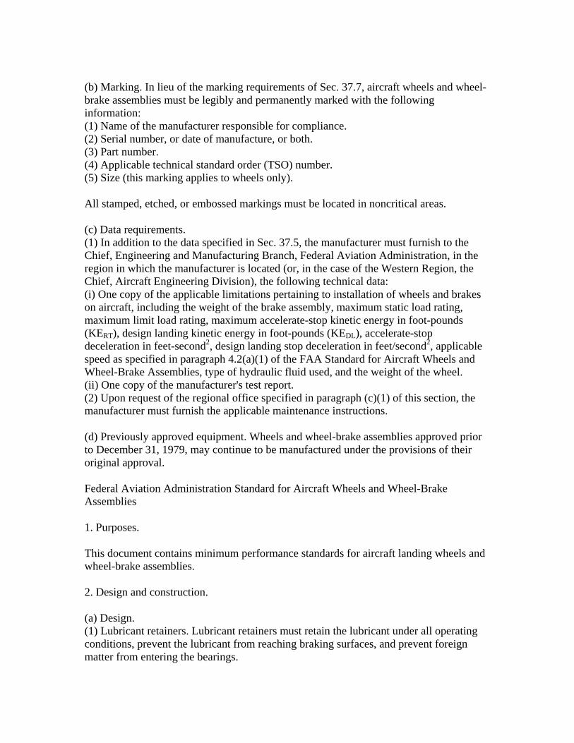
(b) Marking. In lieu of the marking requirements of Sec. 37.7, aircraft wheels and wheel-brake assemblies must be legibly and permanently marked with the following information: (1) Name of the manufacturer responsible for compliance. (2) Serial number, or date of manufacture, or both. (3) Part number. (4) Applicable technical standard order (TSO) number. (5) Size (this marking applies to wheels only). All stamped, etched, or embossed markings must be located in noncritical areas. (c) Data requirements. (1) In addition to the data specified in Sec. 37.5, the manufacturer must furnish to the Chief, Engineering and Manufacturing Branch, Federal Aviation Administration, in the region in which the manufacturer is located (or, in the case of the Western Region, the Chief, Aircraft Engineering Division), the following technical data: (i) One copy of the applicable limitations pertaining to installation of wheels and brakes on aircraft, including the weight of the brake assembly, maximum static load rating, maximum limit load rating, maximum accelerate-stop kinetic energy in foot-pounds (KERT), design landing kinetic energy in foot-pounds (KEDL), accelerate-stop deceleration in feet-second2, design landing stop deceleration in feet/second2, applicable speed as specified in paragraph 4.2(a)(1) of the FAA Standard for Aircraft Wheels and Wheel-Brake Assemblies, type of hydraulic fluid used, and the weight of the wheel. (ii) One copy of the manufacturer's test report. (2) Upon request of the regional office specified in paragraph (c)(1) of this section, the manufacturer must furnish the applicable maintenance instructions. (d) Previously approved equipment. Wheels and wheel-brake assemblies approved prior to December 31, 1979, may continue to be manufactured under the provisions of their original approval. Federal Aviation Administration Standard for Aircraft Wheels and Wheel-Brake Assemblies 1. Purposes. This document contains minimum performance standards for aircraft landing wheels and wheel-brake assemblies. 2. Design and construction. (a) Design. (1) Lubricant retainers. Lubricant retainers must retain the lubricant under all operating conditions, prevent the lubricant from reaching braking surfaces, and prevent foreign matter from entering the bearings.

(2) Removable flanges. All removable flanges must be assembled onto the wheel in a manner that will prevent the removable flange and retaining device from leaving the wheel if a tire should deflate while the wheel is rolling. (3) Adjustment. When necessary to assure safe performance, the brake mechanism must be equipped with suitable adjustment devices. (4) Water seal. Wheels intended for use on amphibious aircraft must be sealed to prevent entrance of water into the wheel bearings or other portions of the wheel or brake, unless the design is such that brake action and service life will not be impaired by the presence of sea water or fresh water. (5) Explosion prevention. Unless determined to be unnecessary, means must be provided to minimize the probability of wheel and tire explosions which result from elevated brake temperatures. (b) Construction. (1) Castings. Castings must be of high quality, clean, sound, and free from blowholes, porosity, or surface defects caused by inclusions, except that loose sand or entrapped gases may be allowed when the serviceability of the casting has not been impaired. (2) Forgings. Forgings must be of uniform condition and free from blisters, fins, folds, seams, laps, cracks, segregation, and other defects. If strength and serviceability are not impaired, imperfections may be removed. (3) Rim surfaces. For wheels designed for use with a tire and inner tube combination, the surface of the rim between bead seats must be free from defects which would be injurious to the inner tube while mounting the tire or while in service. (4) Rim joints. For wheels designed for use with a tire and inner tube combination, joints in the rim surface and joints between rim surfaces and demountable flanges must be smooth, close fitting, and noninjurious to the inner tube while mounting the tire or while in service. (5) Rivets and bolts. When rivets are used, they must be well headed over, and rivets and bolts coming in contact with the casing or tube must be smooth enough not to damage the tube or casing during normal operation. (6) Bolts and studs. When bolts and studs are used for fastening together sections of a wheel, the length of the threads for the nut extending into and bearing against the sections must be held to a minimum and there must be sufficient unthreaded bearing area to carry the required load. (7) Steel parts. All steel parts, except braking surfaces and those parts fabricated from corrosion-resistant steel must be cadmium plated or zinc plated or have equivalent protection from corrosion. (8) Aluminum parts. All aluminum alloy parts must be anodized or have equivalent protection from corrosion. This protection must include protection for fuse plug holes, valve stem holes, and other passages. (9) Magnesium parts. All magnesium alloy parts must receive a suitable dichromate treatment or have equivalent protection from corrosion. This protection must include protection for fuse plug holes, valve stem holes, and other passages. (10) Bearing and braking surfaces. The bearings and braking surfaces must be protected during the application of finish to the wheels and brakes. (11) Fatigue. The construction of the wheel must take into account techniques used to

improve fatigue resistance of critical areas of the wheel. 3. Rating. (a) Each wheel design must be rated for the following: (1) S=Maximum static load in pounds (ref. Secs. 23.731(b), 25.731(b), 27.731(b), and 29.731(b) of this chapter). (2) L=Maximum limit load in pounds (ref. Secs. 23.731(c), 25.731(c), 27.731(c), and 29.731(c) of this chapter). (b) Each wheel-brake assembly design must be rated for the following: (1) KEDL=Kinetic energy capacity in foot-pounds per wheel-brake assembly at the design landing rate of absorption. (2) KERT=Kinetic energy capacity in foot-pounds per wheel-brake assembly at the maximum accelerate-stop rate of absorption for wheel-brake assemblies of airplanes certificated under Part 25 of this chapter only. 4. Qualification tests. The aircraft wheels and wheel-brake assemblies must be tested as follows and the test data included in the applicant's test report required by Sec. 37.172(c)(1)(ii) of this part. 4.1 Wheel tests. To establish the S and L ratings for a wheel, test a standard sample in accordance with he following radial, combined, and static load tests: (a) Maximum radial load test. Test the wheel for yield and ultimate loads as follows: (1) Test method. Mount the wheel with a suitable tire of proper fit installed, on its axle, and position it against a flat nondeflecting surface. The wheel axle must have the same angular orientation to the nondeflecting surface that it will have to the runway when it is mounted on the aircraft and is under the maximum limit load. Inflate the tire to the pressure recommended for the S load with air or water. If water inflation is used, the water must be bled off to obtain the same tire deflection that would result if air inflation were used. Water pressure may not exceed the pressure which would develop if air inflation were used and the tire deflected to its maximum extent. Load the wheel through its axle perpendicular to the flat nondeflecting surface. Deflection readings must be taken at suitable points to indicate deflection and permanent set of the wheel rim at the bead seat. (2) Yield load. Apply to the wheel a load not less than 1.15 times the maximum radial limit load, determined under Secs. 23.471 through 23.511, or Secs. 25.471 through 25.511, or Secs. 27.471 through 27.505, or Secs. 29.471 through 29.511 of this chapter, as appropriate. Apply the load with the wheel positioned against the nondeflecting surface, and the valve hole positioned at 90 degrees with respect to the line between the center of the wheel and the point of contact, then with the valve hole positions 180 degrees, 270 degrees, and 0 degrees from the nondeflecting surface. The 90 degree increments must be altered to other positions if the other positions are more critical. Three successive loadings at the 0 degree position may not cause permanent set increments of increasing magnitude. The permanent set increment caused by the last

loading at the 0 degree position may not exceed 5 percent of the deflection caused by that loading or 0.005 inches, whichever is greater. The bearing cups, cones, and rollers used in operation must be used for these loadings. There must be no yielding of the wheel such as would result in loose bearing cups, air, or water leakage through the wheel or past the wheel seal, or interference in any critical areas. (3) Ultimate load. Apply to the wheel a load, not less than 2 times the maximum radial limit load for castings and 1.5 times the maximum radial limit load for forgings, determined under Secs. 23.471 through 23.511, or Secs. 25.471 through 25.511, or Secs. 27.471 through 27.505, or Secs. 29.471 through 29.511 of this chapter, as appropriate. Apply the load with the same wheel positioned against the nondeflecting surface and the valve hole positioned at 0 degrees with respect to the line between the center of the wheel and the point of contact. The wheel must be able to support the load without failure for at least 3 seconds. The bearing cones may be replaced with conical bushings, but the cups used in operation must be used for this loading. If at a point of loading during the test, it is shown that the tire will not successfully maintain pressure or if bottoming of the tire on the nondeflecting surface occurs, the tire pressure may be increased to no more than 2 times the rated inflation pressure. If bottoming of the tire continues to occurs with this increased pressure, a loading block which fits between the rim flanges and simulates the load transfer of the inflated tire may be used. The arc of wheel supported by the loading block must be no greater than 80 degrees. (4) If the radial limit load in paragraph 4.1(b) is equal to or greater than the maximum radial limit in paragraph 4.1(a)(2) and (3), the tests specified in paragraphs 4.1(a)(2) and (3) may be omitted. (b) Combined radial and side load tests. Tests the wheel for the yield and ultimate loads as follows: (1) Test method. Mount the wheel, with a suitable tire of proper fit installed, on its axle, and position it against a flat nondeflecting surface. The wheel axle must have the same angular orientation to the nondeflecting surface that it will have to the runway when it is mounted on the aircraft and is under the combined radial and side load. Inflate the tire to the pressure recommended for the maximum static load with air or water. If water inflation is used, the water must be bled off to obtain the same tire deflection that would result if air inflation were used. Water pressure may not exceed the pressure which would develop if air inflation were used and the tire deflected to its maximum extent. For the radial load component, load the wheel through its axle perpendicular to the flat nondeflecting surface. For the side load component, load the wheel through its axle parallel to the flat nondeflecting surface. The side load reaction must arise from the friction of the tire or the loading block on the nondeflecting surface. Apply the two loads simultaneously, increasing them either continuously or in increments no longer than 10 percent of the loads to be applied. Alternatively, a resultant load equivalent to the radial and side load may be applied to the axle. Deflection readings must be taken at suitable points to indicate deflection and permanent set of the wheel rim at the bead seat. (2) Yield load. Apply to the wheel radial and side loads not less than 1.15 times the respective ground loads determined under Secs. 23.485, 23.497, and 23.499, or Secs. 25.485, 25.495, 25.497, and 25.499, or Secs. 27.485 and 27.497, or Secs. 29.485 and
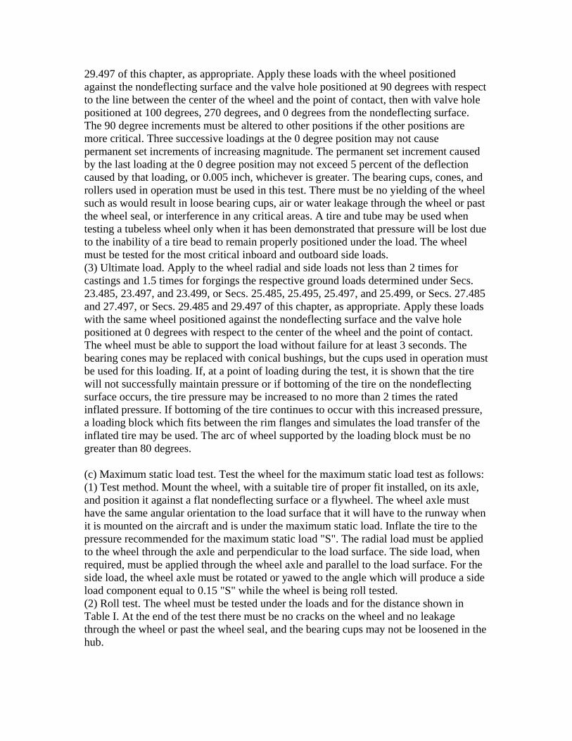
29.497 of this chapter, as appropriate. Apply these loads with the wheel positioned against the nondeflecting surface and the valve hole positioned at 90 degrees with respect to the line between the center of the wheel and the point of contact, then with valve hole positioned at 100 degrees, 270 degrees, and 0 degrees from the nondeflecting surface. The 90 degree increments must be altered to other positions if the other positions are more critical. Three successive loadings at the 0 degree position may not cause permanent set increments of increasing magnitude. The permanent set increment caused by the last loading at the 0 degree position may not exceed 5 percent of the deflection caused by that loading, or 0.005 inch, whichever is greater. The bearing cups, cones, and rollers used in operation must be used in this test. There must be no yielding of the wheel such as would result in loose bearing cups, air or water leakage through the wheel or past the wheel seal, or interference in any critical areas. A tire and tube may be used when testing a tubeless wheel only when it has been demonstrated that pressure will be lost due to the inability of a tire bead to remain properly positioned under the load. The wheel must be tested for the most critical inboard and outboard side loads. (3) Ultimate load. Apply to the wheel radial and side loads not less than 2 times for castings and 1.5 times for forgings the respective ground loads determined under Secs. 23.485, 23.497, and 23.499, or Secs. 25.485, 25.495, 25.497, and 25.499, or Secs. 27.485 and 27.497, or Secs. 29.485 and 29.497 of this chapter, as appropriate. Apply these loads with the same wheel positioned against the nondeflecting surface and the valve hole positioned at 0 degrees with respect to the center of the wheel and the point of contact. The wheel must be able to support the load without failure for at least 3 seconds. The bearing cones may be replaced with conical bushings, but the cups used in operation must be used for this loading. If, at a point of loading during the test, it is shown that the tire will not successfully maintain pressure or if bottoming of the tire on the nondeflecting surface occurs, the tire pressure may be increased to no more than 2 times the rated inflated pressure. If bottoming of the tire continues to occur with this increased pressure, a loading block which fits between the rim flanges and simulates the load transfer of the inflated tire may be used. The arc of wheel supported by the loading block must be no greater than 80 degrees. (c) Maximum static load test. Test the wheel for the maximum static load test as follows: (1) Test method. Mount the wheel, with a suitable tire of proper fit installed, on its axle, and position it against a flat nondeflecting surface or a flywheel. The wheel axle must have the same angular orientation to the load surface that it will have to the runway when it is mounted on the aircraft and is under the maximum static load. Inflate the tire to the pressure recommended for the maximum static load "S". The radial load must be applied to the wheel through the axle and perpendicular to the load surface. The side load, when required, must be applied through the wheel axle and parallel to the load surface. For the side load, the wheel axle must be rotated or yawed to the angle which will produce a side load component equal to 0.15 "S" while the wheel is being roll tested. (2) Roll test. The wheel must be tested under the loads and for the distance shown in Table I. At the end of the test there must be no cracks on the wheel and no leakage through the wheel or past the wheel seal, and the bearing cups may not be loosened in the hub.

Table I Category of aircraft Load conditions Roll distance (miles)Part 25 Maximum static load, "S".
Maximum static load, "S"
plus 0.15 "S" side load applied in outboard
direction.
Maximum static load, "S" plus 0.15 "S" side load
applied in inboard direction.
2000
100
100
Part 23 Maximum static load, "S" 1000Part 27 and 29 Maximum static load, "S" 250 (3) Roll on Rim Test. The wheel without a tire must be tested at a speed not less than 10 mph under the loads and distance shown in Table II. The test axle angular orientation with the load surface must approximate that of the airplane axle to the runway under maximum static load. At the end of the test there may be cracks but no fragmentation of the wheel. (V2=takeoff speed in knots)
Table II Category of aircraft Load conditions Roll distance (feet)Part 25 Maximum static load "S" V22 x 0.5 (d) Pressure test. Pressure test the wheel in accordance with the following: (1) Overpressure test. The wheel must be hydrostatically tested to withstand without failure for at least 3 seconds application of an overpressure factor not less than 4.0 for Part 25 airplanes, 3.5 for Part 23 airplanes, and 3.0 for rotorcraft, times the rate inflation pressure determined by the applicant. (2) Diffusion test. The tubeless tire and wheel assembly must hold the rated inflation pressure for 24 hours with no greater pressure drop than 5 percent. This test must be performed after the tire growth has stabilized. 4.2 Wheel-brake assembly test. A sample of a wheel-brake assembly design, with a suitable tire of proper fit installed, must meet the following tests to qualify the design for its kinetic energy ratings. The wheel of a wheel-brake assembly must be separately tested under paragraph 4.1. The wheel-brake assembly must be tested with the operating medium specified by the manufacturer. (a) Dynamic torque tests. Test the wheel-brake assembly on the suitable inertial brake
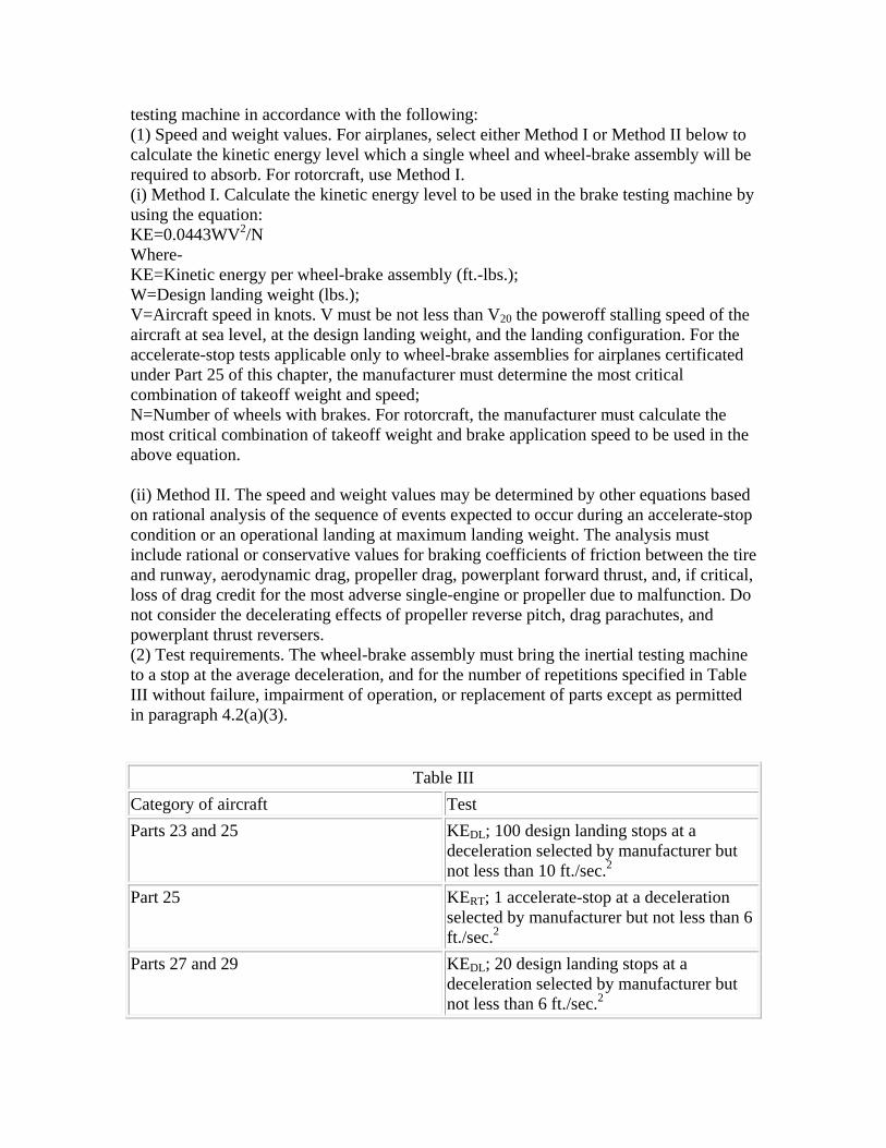
testing machine in accordance with the following: (1) Speed and weight values. For airplanes, select either Method I or Method II below to calculate the kinetic energy level which a single wheel and wheel-brake assembly will be required to absorb. For rotorcraft, use Method I. (i) Method I. Calculate the kinetic energy level to be used in the brake testing machine by using the equation: KE=0.0443WV2/N Where- KE=Kinetic energy per wheel-brake assembly (ft.-lbs.); W=Design landing weight (lbs.); V=Aircraft speed in knots. V must be not less than V20 the poweroff stalling speed of the aircraft at sea level, at the design landing weight, and the landing configuration. For the accelerate-stop tests applicable only to wheel-brake assemblies for airplanes certificated under Part 25 of this chapter, the manufacturer must determine the most critical combination of takeoff weight and speed; N=Number of wheels with brakes. For rotorcraft, the manufacturer must calculate the most critical combination of takeoff weight and brake application speed to be used in the above equation. (ii) Method II. The speed and weight values may be determined by other equations based on rational analysis of the sequence of events expected to occur during an accelerate-stop condition or an operational landing at maximum landing weight. The analysis must include rational or conservative values for braking coefficients of friction between the tire and runway, aerodynamic drag, propeller drag, powerplant forward thrust, and, if critical, loss of drag credit for the most adverse single-engine or propeller due to malfunction. Do not consider the decelerating effects of propeller reverse pitch, drag parachutes, and powerplant thrust reversers. (2) Test requirements. The wheel-brake assembly must bring the inertial testing machine to a stop at the average deceleration, and for the number of repetitions specified in Table III without failure, impairment of operation, or replacement of parts except as permitted in paragraph 4.2(a)(3).
Table III Category of aircraft Test Parts 23 and 25 KEDL; 100 design landing stops at a
deceleration selected by manufacturer but not less than 10 ft./sec.2
Part 25 KERT; 1 accelerate-stop at a deceleration selected by manufacturer but not less than 6 ft./sec.2
Parts 27 and 29 KEDL; 20 design landing stops at a deceleration selected by manufacturer but not less than 6 ft./sec.2
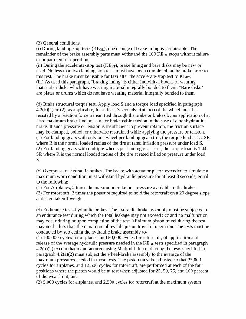
(3) General conditions. (i) During landing stop tests (KEDL), one change of brake lining is permissible. The remainder of the brake assembly parts must withstand the 100 KEDL stops without failure or impairment of operation. (ii) During the accelerate-stop test (KERT), brake lining and bare disks may be new or used. No less than two landing stop tests must have been completed on the brake prior to this test. The brake must be usable for taxi after the accelerate-stop test to KERT. (iii) As used this paragraph, "braking lining" is either individual blocks of wearing material or disks which have wearing material integrally bonded to them. "Bare disks" are plates or drums which do not have wearing material integrally bonded to them. (d) Brake structural torque test. Apply load S and a torque load specified in paragraph 4.2(b)(1) or (2), as applicable, for at least 3 seconds. Rotation of the wheel must be resisted by a reaction force transmitted through the brake or brakes by an application of at least maximum brake line pressure or brake cable tension in the case of a nonhydraulic brake. If such pressure or tension is insufficient to prevent rotation, the friction surface may be clamped, bolted, or otherwise restrained while applying the pressure or tension. (1) For landing gears with only one wheel per landing gear strut, the torque load is 1.2 SR where R is the normal loaded radius of the tire at rated inflation pressure under load S. (2) For landing gears with multiple wheels per landing gear strut, the torque load is 1.44 SR where R is the normal loaded radius of the tire at rated inflation pressure under load S. (c) Overpressure-hydraulic brakes. The brake with actuator piston extended to simulate a maximum worn condition must withstand hydraulic pressure for at least 3 seconds, equal to the following: (1) For Airplanes, 2 times the maximum brake line pressure available to the brakes. (2) For rotorcraft, 2 times the pressure required to hold the rotorcraft on a 20 degree slope at design takeoff weight. (d) Endurance tests-hydraulic brakes. The hydraulic brake assembly must be subjected to an endurance test during which the total leakage may not exceed 5cc and no malfunction may occur during or upon completion of the test. Minimum piston travel during the test may not be less than the maximum allowable piston travel in operation. The tests must be conducted by subjecting the hydraulic brake assembly to- (1) 100,000 cycles for airplanes, and 50,000 cycles for rotorcraft, of application and release of the average hydraulic pressure needed in the KEDL tests specified in paragraph 4.2(a)(2) except that manufacturers using Method II in conducting the tests specified in paragraph 4.2(a)(2) must subject the wheel-brake assembly to the average of the maximum pressures needed in those tests. The piston must be adjusted so that 25,000 cycles for airplanes, and 12,500 cycles for rotorcraft, are performed at each of the four positions where the piston would be at rest when adjusted for 25, 50, 75, and 100 percent of the wear limit; and (2) 5,000 cycles for airplanes, and 2,500 cycles for rotorcraft at the maximum system
pressure available to the brakes. (Secs. 313(a), 601, and 603, Federal Aviation Act of 1958, as amended (49 U.S.C. 1354(a), 1421, and 1423); Sec. 6(c), Department of Transportation Act (49 U.S.C. 1655(c)). Note. - The FAA has determined that this document involves a regulation which is not considered significant under Executive Order 12044, as implemented by DOT Regulatory Policies and Procedures (44 FR 11034; February 26, 1979). A copy of the final evaluation prepared for this action is contained in the regulatory docket. A copy of it may be obtained from the person listed under the heading "FOR FURTHER INFORMATION CONTACT" set forth earlier in this document.
Footer Information Issued in Washington, DC, on November 21, 1979. Langhorne Bond, Administrator. [FR Doc. 79-38543 Filed 11-23-79; 8:45 am] BILLING CODE 4910-13-M
Comments
Document History Notice of Proposed Rulemaking Actions: Notice of Proposed Rulemaking. Notice No. 78-16; Issued on 11/29/78.