cfc-free cft-75 recirculating chiller · the cft recirculating chiller is designed to provide a...
TRANSCRIPT

CFC-Free CFT-75Recirculating Chiller
NESLAB Manual P/N 000008
Rev. 07/31/97
Instruction and Operation Manual

- 1 -
CFT-75 (R134a) Recirculating ChillerInstruction and Operation Manual
PREFACEUnpacking .............................................................................................. 3Warranty ................................................................................................ 3After-sale Support .................................................................................. 3
SECTION ISafety
Warnings ................................................................................................ 4Additional Warnings ................................................................................ 5
SECTION IIGeneral Information
Description ............................................................................................. 6Specifications ......................................................................................... 6
SECTION IIIInstallation
Site ......................................................................................................... 7Electrical Requirements ......................................................................... 8Plumbing Requirements ......................................................................... 8Fluids ..................................................................................................... 9Water Quality Standards and Recommendations .................................. 9Filling Requirements .............................................................................. 11
SECTION IVOperation
Start Up .................................................................................................. 12Fault Lights ............................................................................................ 13
SECTION VMaintenance and
ServiceService Contracts ................................................................................... 14Draining the Reservoir ............................................................................ 14Cleaning ................................................................................................. 14Algae ...................................................................................................... 15Pump Strainer ........................................................................................ 15Pump Lubrication ................................................................................... 16Pressure Relief Valve ............................................................................. 16
SECTION VITroubleshooting
Checklist ................................................................................................ 17Service Assistance ................................................................................. 17
APPENDIXInternational QuickReference Guides
Section VIIWarranty

- 2 -
CFT-75 Quick Reference Operating ProceduresInstallationThe unit has an air-cooled refrigeration system. Airis drawn in the front of the unit and dischargedthrough rear and side. Position the unit so theintake and discharge are not impeded. Inadequateventilation will cause a reduction in cooling capac-ity and, in extreme cases, compressor failure.
Excessively dusty areas should be avoided and aperiodic cleaning schedule should be instituted.For proper operation, the unit needs to pull sub-stantial amounts of air through a condenser. Abuild up of dust or debris on the fins of the con-denser will lead to a loss of cooling capacity.
The unit will retain its full rated capacity in ambienttemperatures up to approximately +38°C.
Make sure the voltage of the power source meetsthe specified voltage, ±10%.
The plumbing connections are located on the rearof the unit and are labelled either SUPPLY andRETURN or OUTLET and INLET. These connec-tions are ½ inch NPT. Connect the SUPPLY fittingto the inlet of the instrument being cooled. Con-nect the RETURN fitting to the outlet of theinstrument being cooled.
To fill the reservoir remove the reservoir accesspanel by unscrewing the thumbscrews. Locate thereservoir plug (square nut). Remove the plug andfill the reservoir with clean cooling fluid.
Tap water is the recommended fluid for operation.
OperationBefore starting the unit, double check all electricaland plumbing connections. Make sure the circulat-ing system has been filled with cooling fluid.
To start the unit, place the Main Power Switch tothe on position. The Power Switch LED illuminatesto indicate the system is operating. To turn the unitoff, place the Power Switch to the off position.
The Cool LED indicates the status of the refrigera-tion system. It illuminates to indicate the refrigera-tion system is removing heat from the coolingfluid. As the operating temperature approaches thesetpoint, the LED will extinguish.
When the unit is shut off, wait approximately fiveminutes before restarting. This allows time for therefrigeration pressures to equalize. If the pressuresare not allowed to equalize, the compressor willshort-cycle and no cooling will occur.
Periodic MaintenancePeriodically inspect the reservoir fluid. If cleaningis necessary, flush the reservoir with a cleaningfluid compatible with the circulating system andthe cooling fluid.
The cooling fluid should be replaced periodically.
Periodic vacuuming of the condenser fins isnecessary. The frequency of cleaning depends onthe operating environment. We recommend avisual inspection of the condenser be mademonthly after initial installation. After severalmonths, the cleaning frequency will be established.
The unit has a pump strainer. If debris is in thesystem, the strainer will prevent the material frombeing drawn into the pump and damaging thepump vanes.
After initial installation, the strainer may becomeclogged. The strainer must be cleaned after thefirst week of installation. After this first cleaning, amonthly visual inspection is recommended. Afterseveral months, the frequency of cleaning will beestablished.
Before cleaning, disconnect the power cord fromthe power source and drain the reservoir.

- 3 -
Preface
ComplianceProducts tested and found to be in compliance with the requirements defined inthe EMC standards defined by 89/336/EEC as well as Low Voltage Directive(LVD) 73/23/EEC can be identified by the CE label on the rear of the unit. Thetesting has demonstrated compliance with the following directives:
LVD, 73/23/EEC Complies with UL 3101-1:93
EMC, 89/336/EEC EN 55011, Class A VerificationEN 50082-1:1992IEC 1000-4-2:1995IEC 1000-4-3:1994IEC 1000-4-4:1995
For any additional information refer to the Letter of Compliance that shippedwith the unit (Declaration of Conformity).
UnpackingRetain all cartons and packing material until the unit is operated and found tobe in good condition. If the unit shows external or internal damage, or does notoperate properly, contact the transportation company and file a damage claim.Under ICC regulations, this is your responsibility.
If this product has been modified to operate at 0°C or lower, it has beentested with a non-freezing fluid. Although the system has been drained,some residual fluid may remain. This will not hinder your unit's performance.
WarrantyUnits have a warranty against defective parts and workmanship for one fullyear from date of shipment. See back page for more details.
After-sale SupportNESLAB is committed to customer service both during and after the sale. Ifyou have questions concerning the operation of your unit, contact our SalesDepartment. If your unit fails to operate properly, or if you have questionsconcerning spare parts or Service Contracts, contact our Customer ServiceDepartment.
Before calling, please refer to the labels on the rear of the unit to obtain thefollowing information:
- unit BOM number ________________________________
- unit serial number ________________________________
- pump type ______________________________________
- 4 -
Section I Safety
WarningsWarnings are posted throughout the manual. These warnings are designatedby an exclamation mark inside an equilateral triangle and text highlighted inbold. Read and follow these important instructions. Failure to observe theseinstructions can result in permanent damage to the unit, significant propertydamage, or personal injury or death.
Make sure you read and understand all instructions and safety precautionslisted in this manual before installing or operating your unit. If you have anyquestions concerning the operation of your unit or the information in thismanual, please contact our Sales Department (see After-sale Support).
Never place the unit in a location where excessive heat, moisture, orcorrosive materials are present.
The unit construction provides extra protection against the risk ofelectrical shock by grounding appropriate metal parts. The extraprotection may not function unless the power cord is connected to aproperly grounded outlet. It is the user's responsibility to assure aproper ground connection is provided.
Never connect the SUPPLY or RETURN fitting to your building watersupply or any water pressure source.
Never use flammable or corrosive fluids with this unit. Distilled anddeionized water may be aggressive and cause material corrosion.Please contact NESLAB before subjecting this unit to prolongedexposure to distilled or deionized water.
Do not use automobile anti-freeze. Commercial anti-freeze containssilicates that can damage the pump seals. Use of automobile anti-freeze will void the manufacturer’s warranty.
Do not replace reservoir plug with a non-vented type or damage tothe tank may occur.
For personal safety and equipment reliability, the following procedureshould only be performed by a competent technician. Contact ourService Department for assistance (see Preface, After-sale Support).
- 5 -
Additional WarningsIn addition to the specific warnings listed on the previous page the followinggeneral warnings apply to your unit:
Performance of installation, operation, or maintenance proceduresother than those described in this manual may result in a hazardoussituation and may void the manufacturer's warranty.
Transport the unit with care. Sudden jolts or drops can damage therefrigeration lines.
Observe all warning labels.
Never remove warning labels.
Never operate damaged or leaking equipment.
Never operate the unit without cooling fluid in the reservoir.
Always turn off the unit and disconnect the power cord from the powersource before performing any service or maintenance procedures, orbefore moving the unit.
Always empty the reservoir before moving the unit.
Never operate equipment with damaged power cords.
Refer service and repairs to a qualified technician.

- 6 -
Section II General Information
DescriptionThe CFT Recirculating Chiller is designed to provide a continuous supply ofcooling fluid at a constant temperature and volume.
The unit consists of an air-cooled refrigeration system, a sealable reservoir,recirculating pump, and a temperature controller.
Throughout the manual, you will be asked to consult the unit’s serial numberlabel or the pump identification label for specific information. Both labels arelocated on the rear of the unit.
Specifications
Cooling Capacity 1
Temperature Range 2
Temperature Stability
Reservoir VolumeLiters
Gallons
Unit Dimessions 3,4
(H x W X D)Centimeters
Inches
Power Requirements
Refrigerant
Pump Capacity
±0.5°
2500 Watts
+5°C to +30°C
6.81.8
67.3 x 37.8 x 65.426½ x 147/8 x 25¾
R134a
50 Hz
4.0
2.0
PSI Bar60
30
P
ress
ure
5 10 15 20 LPM
60 Hz
Flow
1. 2100 Watts at 50Hz. Cooling capacity obtained at 18°C. Cooling capacity will vary depending onfluid temperature, ambient temperature, and cooling fluid.
2. Temperature controller can display from 5°C to 30°C.3. Unit height is measured from the floor to the top of the case. Add 1.3 centimeters (½ inch) to include
the height of the thumbscrews on the reservoir access panel.4. Unit depth is measured from the front of the case to the rear of the electrical enclosure on the back
of the unit.
208/230V, 60Hz220/240V, 50Hz
- 7 -
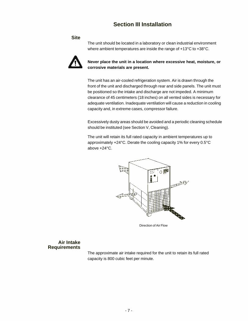
Direction of Air Flow
Section III Installation
SiteThe unit should be located in a laboratory or clean industrial environmentwhere ambient temperatures are inside the range of +13°C to +38°C.
Never place the unit in a location where excessive heat, moisture, orcorrosive materials are present.
The unit has an air-cooled refrigeration system. Air is drawn through thefront of the unit and discharged through rear and side panels. The unit mustbe positioned so the intake and discharge are not impeded. A minimumclearance of 45 centimeters (18 inches) on all vented sides is necessary foradequate ventilation. Inadequate ventilation will cause a reduction in coolingcapacity and, in extreme cases, compressor failure.
Excessively dusty areas should be avoided and a periodic cleaning scheduleshould be instituted (see Section V, Cleaning).
The unit will retain its full rated capacity in ambient temperatures up toapproximately +24°C. Derate the cooling capacity 1% for every 0.5°Cabove +24°C.
Air IntakeRequirements
The approximate air intake required for the unit to retain its full ratedcapacity is 800 cubic feet per minute.

- 8 -
ElectricalRequirements
Refer to Section II, Specifications, and to the serial number label on the rearof the unit for the specific electrical requirements of your unit.
We recommend a harmonized (HAR) grounded 3-conductor cord, type H05,rated 30 amps.
Connect L1 to 1TB1, L2 and N to 1TB3. Connect the grounding conductor tothe grounding stud.
Make sure the voltage of the power source meets the specified voltage, ±10%.
The unit construction provides extra protection against the risk ofelectrical shock by grounding appropriate metal parts. The extraprotection may not function unless the power cord is connected to aproperly grounded outlet. It is the user's responsibility to assure aproper ground connection is provided.
The unit can operate with either 50 Hertz or 60 Hertz input frequency. Tochange the frequency remove the wrapper and locate terminal boards 1TBand 2TB at the rear of the unit. For 50 Hertz operation, connect 2TB2 to 1TB2.For 60 Hertz, connect 2TB2 to 1TB1.
PlumbingRequirements
Before installing the unit to an instrument that previously used tap water as acooling fluid, flush the instrument several times to remove any rust or scalethat has built up. The manufacturer of the instrument should be able to .recommend a cleaning fluid for their equipment.
The plumbing connections are located on the rear of the unit and are labelledSUPPLY and RETURN. The connections are ½ inch NPT.
Connect the SUPPLY fitting to the inlet of the instrument being cooled. Con-nect the RETURN fitting to the outlet of the instrument being cooled.
Never connect the fittings to your building water supply or any waterpressure source.
Flexible tubing, if used, should be of heavy wall or reinforced construction. Alltubing should be rated to withstand 80 psig at +30°C. Make sure alltubing connections are securely clamped. Avoid running tubing near radiators,hot water pipes, etc. If substantial lengths of tubing are necessary, insulationmay be required to prevent loss of cooling capacity.
Tubing and insulation are available from NESLAB. Contact our Sales Depart-ment for more information (see Preface, After-sale Support).
- 9 -
It is important to keep the distance between the unit and the instrumentbeing cooled as short as possible, and to use the largest diameter tubingpractical. Tubing should be straight and without bends. If diameter reductionsmust be made, they should be made at the inlet and outlet of the instrumentbeing cooled, not at the CFT.
If substantial lengths of cooling lines are required, they should be pre-filledwith cooling fluid before connecting them to the unit.
FluidsThe selected fluid must have a viscosity of 50 centistokes or less at thelowest operating temperature.
Never use flammable or corrosive fluids with this unit. Distilled anddeionized water may be aggressive and cause material corrosion.Please contact NESLAB before subjecting this unit to prolongedexposure to distilled or deionized water.
Tap water is the recommended fluid for normal operation, see Water Qualityand Recommendations.
Below +8°C, a non-freezing fluid must be used. A mixture of tap water andlaboratory grade ethylene glycol is suggested.
Do not use automobile anti-freeze. Commercial anti-freeze containssilicates that can damage the pump seals. Use of automobileanti-freeze will void the manufacturer’s warranty.
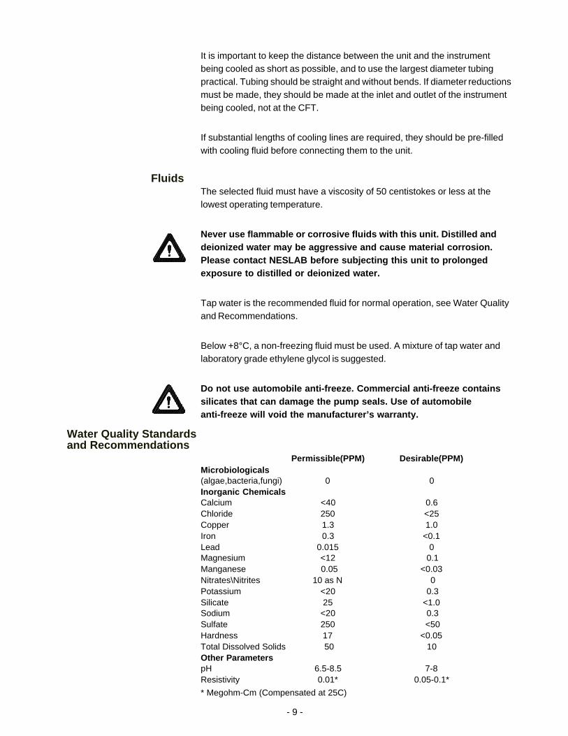
Water Quality Standardsand Recommendations
Permissible(PPM) Desirable(PPM)Microbiologicals(algae,bacteria,fungi) 0 0Inorganic ChemicalsCalcium <40 0.6Chloride 250 <25Copper 1.3 1.0Iron 0.3 <0.1Lead 0.015 0Magnesium <12 0.1Manganese 0.05 <0.03Nitrates\Nitrites 10 as N 0Potassium <20 0.3Silicate 25 <1.0Sodium <20 0.3Sulfate 250 <50Hardness 17 <0.05Total Dissolved Solids 50 10Other ParameterspH 6.5-8.5 7-8Resistivity 0.01* 0.05-0.1*
* Megohm-Cm (Compensated at 25C)

- 10 -
Unfavorably high total ionized solids (TIS) can accelerate the rate of galvaniccorrosion. These contaminants can function as electrolytes which increasethe potential for galvanic cell corrosion and lead to localized corrosion suchas pitting which can be observed at the studs and on the outside surface ofcooling coils. Eventually, the pitting will become so extensive that the coil willleak refrigerant into the water reservoir.
As an example, raw water in the United States averages 171 ppm (as NaCl).The recommended level for use in a water system is between 0.5 to 5.0 ppm(as NaCl).
Recommendation: Initially fill the tank with distilled/deionized water. Do notuse untreated tap water as the total ionized solids level may be too high.
Maintain this water quality at a resistivity of between 1 to 10 megohm-cm(compensated at 25°C) by using a purification system. Although the initial fillmay be as high as 10 megohm-cm (compensated at 25°C), the desired levelfor long time usage is 1 to 3 megohm-cm (compensated at 25°C).
The above two recommendations will reduce the electrolytic potential of thewater and prevent or reduce the galvanic corrosion observed.
Res
istiv
ity (
meg
ohm
-cm
@ 2
5°C
) Not Recommended, Increasingly Corrosive
Operations with Stainless Steel Systems
Operations withMixed MetalsCopper/Brass/Stainless Steel CONSULT MATERIALS ENGINEER
10 20 30 40 50 60 70 80
18.30
15.00
10.00
3.00
1.00
0.10
0.05
Water Quality Considerations
Temperature °C

- 11 -
Filling RequirementsRemove the reservoir access panel by unscrewing the thumbscrews. Locatethe reservoir plug (square nut). Remove the plug and fill the reservoir withclean cooling fluid, following the special considerations outlined in thefollowing paragraphs.
Circulating to a closed system (closed to the atmosphere)Fill the reservoir to the bottom of the fill hole threads. Since the reservoircapacity is small compared to many instruments being cooled, have extracooling fluid on hand to keep the system topped off when external circulationis started.
NOTE: The tank in your unit has a vent which relieves pressure built up fromthermal expansion of water. The vent is located on the reservoir plug. Itactivates when tank pressure reaches 3 - 5 psi.
Do not replace reservoir plug with an non-vented type or damage tothe tank may occur.
Circulating to an open system (open to the atmosphere)Fill the reservoir so ¾ of the fill hole threads are covered. Wrap the tankplug with Teflon® sealing tape. Replace the tank plug and tighten securely toprevent air entry.
When circulating cooling fluid to an open system, connect the SUPPLY andRETURN lines to the open tank. Secure the RETURN (suction) line below thefluid surface. The RETURN line should be submerged deep enough to avoidsucking air. Make sure the RETURN line is free of particles and debris that canblock the flow of fluid. A baffle or screen may be required.
Thumbscrew
Reservoir Access Panel
Reservoir Plug
Reservoir Filling Locations (Typical)

- 12 -
Section IV Operation
Start UpBefore starting the unit, double check all electrical and plumbing connectionsand make sure the circulating system (the CFT, the instrument being cooled,and the tubing that connects them) has been properly filled with cooling fluid.
To start the unit, place the POWER Switch to the ON position. The controllerLEDs will illuminate.
Applying power to pins 1 and 2 on the Metrimate receptacle located on therear of the unit starts the refrigeration system and the recirculation pump. Seenext page.
The COOL LED on the front panel indicate the status of the refrigerationsystem. It illuminates to indicate the refrigeration system is removing heatfrom the cooling fluid. As the operating temperature approaches thetemperature setpoint, the LED will extinguish.
TemperatureController
Temperature AdjustmentTo display the temperature setpoint, press and hold the DISPLAY switch. Toadjust the temperature setpoint, press and hold the DISPLAY switch and turnthe ADJUST knob until the desired temperature setpoint is indicated on thedigital display. Once the setpoint is adjusted, release the DISPLAY switch. Thedisplay will now indicate the temperature of the fluid in the reservoir.
NOTE: Inadvertent movement of the ADJUST knob, regardless of the positionof the DISPLAY switch, will result in a change in the setpoint. This change willnot be immediately reflected on the digital display, unless the DISPLAY switchis pressed. The digital display will eventually change as the unit reacts to thenew setpoint.
Controller

- 13 -
Shut DownTo turn the unit off, place the POWER Switch to the OFF position.
When the unit is shut off, wait approximately five minutes before restarting.This allows time for the refrigeration pressures to equalize. If the pressuresare not allowed to equalize, the compressor will short-cycle (clicking sound)and no cooling will occur.
Fault LightsShould the fluid flow drop below 1.6 liters per minute the FLOW lamp willilluminate and a signal will be sent to the Metrimate receptacle on the rear ofthe unit, see below.
Should the temperature of the fluid in the tank exceed what is set on the HighTemperature Cutout (HTC), the TEMP lamp will illuminate and a signal will besent to the Metrimate receptacle on the rear of the unit, see below. The HTCis factory preset at 30°C (86°F).
NOTE: The temperature scale on the HTC is in °F.
6-pin Metrimate ReceptacleConnector is made by AMP, Part Number 207153-1Pin Part Number 745652-2
Front Panel Switch
Contactor
TempFlow
1
2
3
4
5

- 14 -
Section V Maintenance and Service
For personal safety and equipment reliability, the following procedureshould only be performed by a competent technician. Contact ourService Department for assistance (see Preface, After-sale Support).
Service ContractsNESLAB offers on-site Service Contracts that are designed to provideextended life and minimal down-time for your unit. For more information,contact our Service Department (see Preface, After-sale Support).
Draining theReservoir
To drain the reservoir we recommend the use of a wet/dry vacuum. Removethe reservoir plug and carefully insert the wet/dry vacuum so as not to damagethe cooling coils. NOTE: Tilting the unit more than 45° may allow compressoroil to seep into the suction line.
CleaningReservoirPeriodically inspect the fluid inside the reservoir. If cleaning is necessary,flush the reservoir with a cleaning fluid compatible with the circulatingsystem and the cooling fluid.
The cooling fluid should be replaced periodically. When operating at lowtemperatures, the concentration of water in the cooling fluid will increaseover time, leading to a loss of cooling capacity.
Before changing the cooling fluid, raise the operating temperature of the unitto de-ice the cooling coils. Refer to Section III, Filling Requirements for instruc-tions on replacing the cooling fluid.
CondenserFor proper operation, the unit needs to pull substantial amounts of airthrough a condenser. A build up of dust or debris on the fins of the condenserwill lead to a loss of cooling capacity.
The lower front of the unit has a one-piece grille assembly. Gently pry theassembly off with a flathead screwdriver. Use care not to scratch the paint.
Periodic vacuuming of the condenser fins is necessary. The frequency ofcleaning depends on the operating environment. It is recommended that avisual inspection of the condenser be made monthly after initial installation.After several months, the frequency of cleaning will be established.
- 15 -
AlgaeTo restrict the growth of algae in the reservoir, it is recommended that thereservoir cover be kept in place and that all circulation lines be opaque. Thiswill eliminate the entrance of light which is required for the growth of mostcommon algae.
NESLAB recommends the use of Chloramine-T, one gram per gallon.
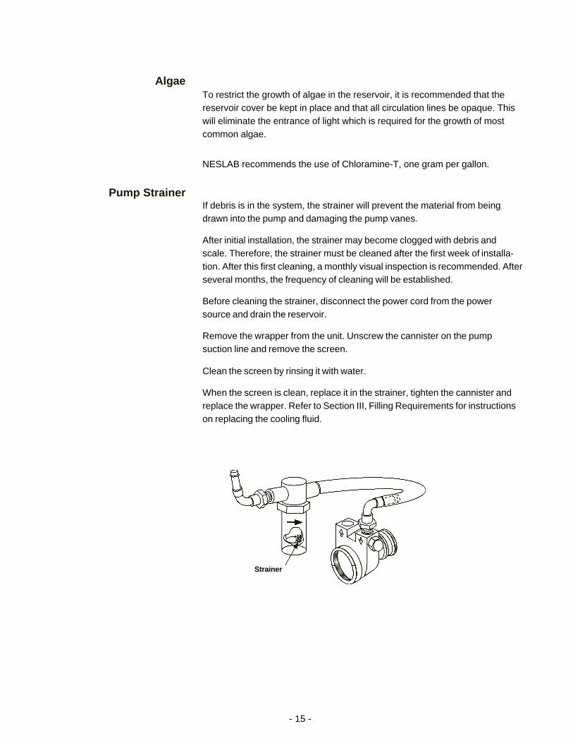
Pump StrainerIf debris is in the system, the strainer will prevent the material from beingdrawn into the pump and damaging the pump vanes.
After initial installation, the strainer may become clogged with debris andscale. Therefore, the strainer must be cleaned after the first week of installa-tion. After this first cleaning, a monthly visual inspection is recommended. Afterseveral months, the frequency of cleaning will be established.
Before cleaning the strainer, disconnect the power cord from the powersource and drain the reservoir.
Remove the wrapper from the unit. Unscrew the cannister on the pumpsuction line and remove the screen.
Clean the screen by rinsing it with water.
When the screen is clean, replace it in the strainer, tighten the cannister andreplace the wrapper. Refer to Section III, Filling Requirements for instructionson replacing the cooling fluid.
Strainer
- 16 -
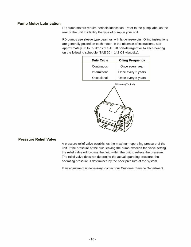
Pump Motor LubricationPD pump motors require periodic lubrication. Refer to the pump label on therear of the unit to identify the type of pump in your unit.
PD pumps use sleeve type bearings with large reservoirs. Oiling instructionsare generally posted on each motor. In the absence of instructions, addapproximately 30 to 35 drops of SAE 20 non-detergent oil to each bearingon the following schedule (SAE 20 = 142 CS viscosity):
Duty Cycle Oiling Frequency
Continuous Once every year
Intermittent Once every 2 years
Occasional Once every 5 years
Fill Holes (Typical)
Pressure Relief ValveA pressure relief valve establishes the maximum operating pressure of theunit. If the pressure of the fluid leaving the pump exceeds the valve setting,the relief valve will bypass the fluid within the unit to relieve the pressure.The relief valve does not determine the actual operating pressure; theoperating pressure is determined by the back pressure of the system.
If an adjustment is necessary, contact our Customer Service Department.

- 17 -
Section VI Troubleshooting
Checklist
Unit will not startCheck the line cord, make sure it is plugged in.
Check the voltage of the power source. Make sure it is within the ratedvoltage of the unit, ±10%.
Unit will not circulate fluid
Check the reservoir level. Fill, if necessary.
Make sure the pump has been purged.
Check the pressure gauge. If the reading is 60 psig, check the instrumentbeing cooled for restrictions in the cooling line.
Check the pump strainer. A clogged strainer can starve the pump.
Inadequate temperature controlIf the temperature continues to rise, make sure the heat load of theinstrument being cooled does not exceed the rated specification. (SeeSection II, Specifications).
Make sure the air intake and discharge are not impeded and the ambienttemperature does not exceed +38°C.
Make sure the condenser is free of dust and debris. (See Section V,Cleaning.)
If the compressor short-cycles (a clicking sound), check the line voltage.It should be within the 10% of the specified voltage. Wait 5 minutesbefore restarting the unit.
Service AssistanceIf, after following these troubleshooting steps, your unit fails to operateproperly, contact our Service Department for assistance (see Preface, After-sale Support). Before calling, please refer to the serial number label on therear of the unit to obtain the following information:
- unit BOM number- unit serial number- voltage of unit- voltage of power source

Blank page.

CFT - Umlaufkühler KurzbedienungsanleitungInstallationDas Gerät verfügt über ein luftgekühltesKühlsystem. Die Luft wird an der Vorderseiteangesaugt und strömt an den Seitenwänden undan der Rückseite aus. Das Gerät muß so plaziertwerden, daß weder die Ansaug- noch dieAusströmungsöffnungen blockiert sind. Beiungenügender Ventilation wird die Kühlleistungreduziert und kann in extremen Situationen zueinem Ausfall des Kühlsystems (Kompressors)führen.
Aufstellorte mit hoher Staubentwicklung solltenvermieden werden, und es sollte eineregelmäßige Reinigung des Gerätes durchgeführtwerden. Um einwandfrei zu funktionieren, mußdas Gerät große Luftmengen durch denKondensor ansaugen. Bei Staub- undSchmutzablagerungen auf demKondensorheizkörper kommt es zu einem Verlustvon Kühlleistung.
Das Gerät behält seine maximale Kühlleistung biszu einer Umgebungstemperatur von ca. +38°C.
Vergewissern Sie sich, daß die Spannung IhrerStromanschlüsse mit der für das Gerätvorgesehenen Spannung übereinstimmt (+10%).
Die Schlauchanschlüsse (1/2 Zoll FPT) desGerätes befinden sich an der Rückseite und sindmit SUPPLY und RETURN bezeichnet. Bitteentfernen Sie die Gummiabdichtung von beidenAnschlüssen. Schließen Sie den SUPPLY-Anschluß an den Eingang Ihres Instruments undden RETURN-Anschluß an den Ausgang IhresInstruments an.
Um das Reservoir zu füllen, entfernen Sie denReservoir-Schutzdeckel, indem Sie dieFlügelschrauben lösen. Entfernen Sie denReservoirverschluß (viereckige Mutter) und füllenSie das Reservoir mit sauberer Kühlflüssigkeit.
Für den Betrieb im Arbeits-Temperaturbereich von+8°C bis +30°C empfiehlt NESLABLeitungswasser als Kühlmittel.
InbetriebnahmeVor Inbetriebnahme des Gerätes vergewissern Siesich bitte, daß die elektrischen Anschlüsse und dieRohr- u. Schlauchanschlüsse sachgemäßinstalliert sind und daß das gesamte System mitKühlflüssigkeit gefüllt ist.
Um das Gerät einzuschalten, müssen Sie denHauptschalter auf „ON“ stellen. Der Schalterleuchtet auf, wenn das Gerät in Betrieb ist. Umdas Gerät abzuschalten, muß der Hauptschalterauf „OFF“ gestellt werden.
Die „Cool“ LED-Anzeige an der Anzeigetafel aufder Vorderseite des Gerätes leuchtet auf, so langedas Kühlsystem der Kühlflüssigkeit Wärmeentzieht. Ist die gewünschte Temperatur erreicht(setpoint), erlischt die LED-Anzeige.
Nach dem Ausschalten des Gerätes sollten Sievor dem Wiedereinschalten ca. 5 Minuten warten,damit das Kühlsystem einen Druckausgleichdurchführen kann. Beachtet man diese Wartezeitnicht, kommt es zu kurzen Schaltfrequenzen desKompressors und eine Kühlung ist nicht möglich.
Einstellung der Analog-TemperatursteuerungUm die Temperatur einzustellen (setpoint), drehenSie den °C-Schalter an der Vorderseite desGerätes auf die gewünschte Temperatur.
Einstellung der Digital-TemperatursteuerungUm sich den Temperatur-Setpoint anzeigen zulassen, drücken Sie den DISPLAY-Schalter undhalten Sie ihn gedrückt. Um den Temperatur-Setpoint einzustellen, drücken Sie den Display-Schalter, halten diesen, und drehen gleichzeitigden ADJUST-Schalter so lange, bis diegewünschte Temperatur in der Digitalanzeigeangezeigt wird. Wenn die Temperatur eingestelltist, lassen Sie den Display-Schalter los. DieDigitalanzeige zeigt dann die Temperatur derKühlflüssigkeit im Reservoir an.
Appendix International QuickReference Guides

WartungÜberprüfen Sie regelmäßig die Kühlflüssigkeit imReservoir. Sollte eine Säuberung notwendig sein,spülen Sie das Reservoir mit einer speziellenReinigungsflüssigkeit, die mit dem Umlaufsystemund der Kühlflüssigkeit kompatibel ist.
Das Kühlmittel sollten Sie regelmäßig erneuern.
Regelmäßiges Absaugen des Kondensor-Heizkörpers ist erforderlich. DieReinigungshäufigkeit hängt von derBetriebsumgebung ab. Eine monatlicheÜberprüfung des Kondensors ist empfehlenswert.So werden Sie nach einigen Monaten einenReinigungsrhythmus gefunden haben.
Geräte mit PD-Pumpen sind mit einemPumpenfilter ausgestattet. Der Filter sorgt dafür,daß kleine Teilchen und Schmutzablagerungennicht in die Pumpe gelangen und so diePumpflügel beschädigen können.
Nach der Erstinstallation kann es zu einerBlockierung des Filters kommen. Die ersteReinigung sollte daher nach einer Wocheerfolgen. Danach empfehlen wir eine monatlicheÜberprüfung des Filters. So können Sie nacheiniger Zeit abschätzen, wie oft der Filter gereinigtwerden muß.
Bevor Sie den Filter reinigen, ziehen Sie denNetzstecker aus der Steckdose und leeren Sie dasReservoir.
CFT Serie Kvik Referance
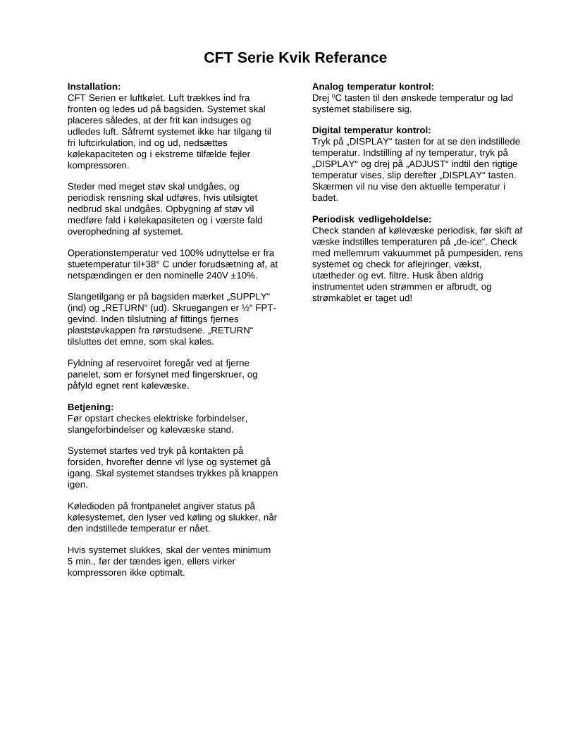
Installation:CFT Serien er luftkølet. Luft trækkes ind frafronten og ledes ud på bagsiden. Systemet skalplaceres således, at der frit kan indsuges ogudledes luft. Såfremt systemet ikke har tilgang tilfri luftcirkulation, ind og ud, nedsætteskølekapaciteten og i ekstreme tilfælde fejlerkompressoren.
Steder med meget støv skal undgåes, ogperiodisk rensning skal udføres, hvis utilsigtetnedbrud skal undgåes. Opbygning af støv vilmedføre fald i kølekapasiteten og i værste faldoverophedning af systemet.
Operationstemperatur ved 100% udnyttelse er frastuetemperatur til+38° C under forudsætning af, atnetspændingen er den nominelle 240V ±10%.
Slangetilgang er på bagsiden mærket „SUPPLY“(ind) og „RETURN“ (ud). Skruegangen er ½“ FPT-gevind. Inden tilslutning af fittings fjernesplaststøvkappen fra rørstudsene. „RETURN“tilsluttes det emne, som skal køles.
Fyldning af reservoiret foregår ved at fjernepanelet, som er forsynet med fingerskruer, ogpåfyld egnet rent kølevæske.
Betjening:Før opstart checkes elektriske forbindelser,slangeforbindelser og kølevæske stand.
Systemet startes ved tryk på kontakten påforsiden, hvorefter denne vil lyse og systemet gåigang. Skal systemet standses trykkes på knappenigen.
Køledioden på frontpanelet angiver status påkølesystemet, den lyser ved køling og slukker, nården indstillede temperatur er nået.
Hvis systemet slukkes, skal der ventes minimum5 min., før der tændes igen, ellers virkerkompressoren ikke optimalt.
Analog temperatur kontrol:Drej 0C tasten til den ønskede temperatur og ladsystemet stabilisere sig.
Digital temperatur kontrol:Tryk på „DISPLAY“ tasten for at se den indstilledetemperatur. Indstilling af ny temperatur, tryk på„DISPLAY“ og drej på „ADJUST“ indtil den rigtigetemperatur vises, slip derefter „DISPLAY“ tasten.Skærmen vil nu vise den aktuelle temperatur ibadet.
Periodisk vedligeholdelse:Check standen af kølevæske periodisk, før skift afvæske indstilles temperaturen på „de-ice“. Checkmed mellemrum vakuummet på pumpesiden, renssystemet og check for aflejringer, vækst,utætheder og evt. filtre. Husk åben aldriginstrumentet uden strømmen er afbrudt, ogstrømkablet er taget ud!
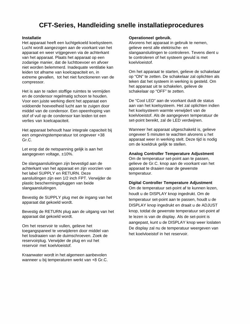
CFT-Series, Handleiding snelle installatieprocedures
InstallatieHet apparaat heeft een luchtgekoeld koelsysteem.Lucht wordt aangezogen aan de voorkant van hetapparaat en weer vrijgegeven via de achterkantvan het apparaat. Plaats het apparaat op eenzodanige manier, dat de luchttoevoer en afvoerniet worden belemmerd. Inadequate ventilatie kanleiden tot afname van koelcapaciteit en, inextreme gevallen, tot het niet functioneren van decompressor.
Het is aan te raden stoffige ruimtes te vermijdenen de condensor regelmatig schoon te houden.Voor een juiste werking dient het apparaat eenvoldoende hoeveelheid lucht aan te zuigen doormiddel van de condensor. Een opeenhoping vanstof of vuil op de condensor kan leiden tot eenverlies van koelcapaciteit.
Het apparaat behoudt haar integrale capaciteit bijeen omgevingstemperatuur tot ongeveer +38Gr.C.
Let erop dat de netspanning gelijk is aan hetaangegeven voltage, ±10%.
De slangaansluitingen zijn bevestigd aan deachterkant van het apparaat en zijn voorzien vanhet label SUPPLY en RETURN. Dezeaansluitingen zijn een 1/2 inch FPT. Verwijder deplastic beschermingspluggen van beideslangaansluitingen.
Bevestig de SUPPLY plug met de ingang van hetapparaat dat gekoeld wordt.
Bevestig de RETURN plug aan de uitgang van hetapparaat dat gekoeld wordt.
Om het reservoir te vullen, gelieve hettoegangspaneel te verwijderen door middel vanhet losdraaien van de duimschroeven. Zoek dereservoirplug. Verwijder de plug en vul hetreservoir met koelvloeistof.
Kraanwater wordt in het algemeen aanbevolenwanneer u bij temperaturen werkt van +8 Gr.C.
Operationeel gebruik.Alvorens het apparaat in gebruik te nemen,gelieve eerst alle elektrische- enslangaansluitingen te controleren. Tevens dient ute controleren of het systeem gevuld is metkoelvloeistof.
Om het apparaat te starten, gelieve de schakelaarop “ON” te zetten. De schakelaar zal oplichten alsteken dat het systeem in werking is gesteld. Omhet apparaat uit te schakelen, gelieve deschakelaar op “OFF” te zetten.
De “Cool LED” aan de voorkant duidt de statusaan van het koelsysteem. Het zal oplichten indienhet koelsysteem warmte verwijdert van dekoelvloeistof. Als de aangegeven temperatuur deset-point bereikt, zal de LED verdwijnen.
Wanneer het apparaat uitgeschakeld is, gelieveongeveer 5 minuten te wachten alvorens u hetapparaat weer in werking stelt. Deze tijd is nodigom de koeldruk gelijk te stellen.
Analog Controller Temperature AdjustmentOm de temperatuur set-point aan te passen,gelieve de Gr.C. knop aan de voorkant van hetapparaat te draaien naar de gewenstetemperatuur.
Digital Controller Temperature AdjustmentOm de temperatuur set-point af te kunnen lezen,houdt u de DISPLAY knop ingedrukt. Om detemperatuur set-point aan te passen, houdt u deDISPLAY knop ingedrukt en draait u de ADJUSTknop, totdat de gewenste temperatuur set-point afte lezen is van de display. Als de set-point isaangepast, kunt u de DISPLAY knop weer loslatenDe display zal nu de temperatuur weergeven vanhet koelvloeistof in het reservoir.
Periodiek OnderhoudHet reservoir dient regelmatig gecontroleerd teworden. Indien reiniging noodzakelijk is, zal hetreservoir schoongespoeld moeten worden meteen vloeistof, welke gelijk is aan het koelsysteemen het koelvloeistof.
Het koelvloeistof dient periodiek vervangen teworden.
Het periodiek luchtvrij maken van de condensor isnoodzakelijk. Het aantal malen dat dit moetgebeuren, hangt af van de omgeving waar hetapparaat staat opgesteld en wordt gebruikt. Wijraden een algemene maandelijkse inspektie vande condensor aan na de installatie. Na enkelemaanden zal duidelijk zijn hoe vaak men hetapparaat moet reinigen.
Apparaten met PD-pompen hebben een filter.Indien vuil in het systeem aanwezig is, zal de filterervoor zorgdragen dat het materiaal niet in depomp terecht komt en daardoor de pomp nietwordt beschadigd.
Nadat het apparaat geinstalleerd is, kan de filterverstopt raken. De filter zal schoongemaaktmoeten worden in de eerste week na installatie.Nadat dit gebeurd is, is een maandelijkseinspektie aan te raden. Na enkele maanden zalduidelijk zijn hoe vaak de filter gereinigd moetworden.
Alvorens de filter te reinigen, gelieve het apparaatuit te schakelen en het reservoir te ledigen.

Kortfattad Bruksanvisning för CFT SerieInstallationMaskinen har ett luft kylt kylnings system. Luft tasin på framsidan av maskinen och släpps ut påsidan och baksidan av maskinen. Ställ maskinenså att intaget och uttaget inte är blockerade.Otillräcklig ventilation leder till minskadkylningskapacitet och i vissa fall kan kompressorngå sönder.
Undvik dammiga områden och rengör maskinenperiodiskt. För att fungera ordentligt måstemycket luft passera genom kondensorn. Dammoch smuts i kondensorn leder till minskad kylningskapacitet.
Maskinen har full kylningskapacitet upp till entemperatur av +100°F (38°C).
Röranslutning finns på baksidan av maskinen ochhar följande beskrivning: SUPPLY och RETURN.Anslutningarna är 1/2 inch FPT. Ta bort deskyddande plast bitarna från röranslutningarna.Anslut SUPPLY kopplingen till intaget av dinanordning och RETURN kopplingen till uttaget.
Lösgör skruvarna och ta bort luckan för att fyllatanken. Ta bort tank pluggen och fyll tanken medren kylnings vätska.
Vanligt kran vatten är den rekommenderadevätskan vid en temperatur mellan +8°C och+80°C.
AnvändningInnan maskinen startas, kontrollera alla elektriskaoch alla rör anslutningar. Se till att cirkulationssystemen har fyllts med vätska.
Sätt start knappen på ON för att starta maskinen.COOL och IDLE på framsidan visar statusen påkylningssystemet. Cool lyser när värme tas bortfrån köldmedlet. När temperaturen närmar sigden förbestämda temperaturen kommer de två attväxla.
Vänta 5 minuter efter att maskinen stämgts avinnan den sätts på igen för att låta kylningstryckenatt utjämnas. Ingen kylning kommer att utförasom inte trycken tillåts att utjämnas.
Analog Kontroll, Temperatur ÄndringFör att ändra den önskade förbestämdatemperaturen, vrid °C knappen på framsidan avmaskinen tills den önskade temperaturen är nådd.
Digital Kontroll, Temperatur ÄndringHåll Display knappen intryckt för att visa denönskade temperaturen. Håll Display knappenintryckt och vrid Adjust knappen för att ändra denönskade temperaturen. Släpp Display knappenefter att den önskade temperaturen visas påkontroll panelen. Temperaturen på vätskan itanken visas nu på kontroll panelen.
Periodiskt UnderhållInspektera vätskan i tanken periodiskt. Omrengöring är nödvändigt, spola tanken med enrengörings vätska som är förenlig medcirkulationssystemet och kylvätskan.
Kylvätskan bör bytas periodvis.
Periodisk rengöring av kondensorn är nödvändig.Hur ofta rengöring är nödvändig beror på miljön.Vi rekommenderar en visuell inspektion avkondensorn varje månad efter installation. Efterflera månader kan det avgöras hur oftakondensorn måste rengöras i framtiden.
Maskiner med PD pumpar har ett filter. Filtretmåste rengöras efter en veckas användning.Efter första rengöringen bör filtret inspekterasvarje månad. Efter flera månader kan detavgöras hur ofta filtret måsta rengöras.
Innan filtret rengörs, drag ur kontakten och tömtanken.
All annan information inklusive felsökning finnsbeskriven i instruktions manualen.

NOTICE D’UTILISATIONREFROIDISSEURS TYPE CFT
INSTALLATIONCes appareils ont un système de réfrigérationrefroidi par air. L’air est aspiré sur le devant etrejeté à l’arrière et sur les côtés
Positionner l’appareil afin que l’admission etl’émission ne soient pas obstruées. Uneventilation insuffisante serait la cause d’uneréduction de la capacité de refroidissement, voire,d’une défaillance du compresseur.
Une zone excessivement poussièreuse lenettoyage périodique est recommandé. En modede fonctionnement, l’appareil aspire de l’air àtravers le condenseur. De la poussière et desparticules sur la grille atténueraient sa capacité derefroidissement.
L’appareil conserve sa pleine puissance derefroidissement sur une plage de températureallant de l’ambiante à + 38°C.
S’assurer que l’alimentation électrique soit cellerequise à ±10%.
Les connections, d’un diamètre 0.5 pouce FPT,sont situées à l’arrière de l’appareil et sontréférencées “ SUPPLY ” et “ RETURN ”.. Retirerles embouts plastiques. Connecter le tuyauenfiché sur “ SUPPLY ” vers l’entrée del’équipement et celui sur “ RETURN ” vers lasortie.
Pour remplir le réservoir, ôter la tape à l’aide desdeux vis.
MISE EN ROUTEVérifier les connections électriques, les tuyauxd’eau et le niveau de remplissage du liquide.
Mettre en route en appuyant sur “ ON ”. Un voyants’allume qui indique que l’appareil est enfonctionnement. Pour l’éteindre, appuyer sur“ OFF ”.
Le voyant LED “ Cool ” allumé indique le mode defonctionnement du système de réfrigération.Lorsque la température requise est atteinte, cevoyant s’éteint.
Après avoir éteint l’appareil, attendre environ cinqminutes avant de le rallumer, pour un bonéquilibrage des pressions.Autrement, le cycle au
niveau du compresseur serait trop bref et lerefroidissement n’aurait pas lieu.
REGLAGE DU CONTROLEUR DETEMPERATURE ANALOGIQUETourner le potentiomètre situé à l’avant jusqu’à ceque la température désirée coïncide avec lagraduation.
REGLAGE DU CONTROLEUR DETEMPERATURE NUMERIQUEPour afficher la température souhaitée, maintenirappuyé l’interrupteur et tourner le bouton deréglage jusqu’à ce que la température souhaitéesoit affichée. Relâcher ensuite l’interrupteur.L’affichage indique alors la température du fluidedans le réservoir.
MAINTENANCE PREVENTIVEVérifier régulièrement le niveau du réservoir,
Changer de temps à autre le liquide utilisé,
En cas de nettoyage, rincer avec un produit delavage compatible,
Avant de changer de liquide, recirculer à unetempérature plus élevée pour réchauffer leserpentin,
Nettoyer régulièrement selon les conditions detravail la grille d’aspiration. Nous recommandonsd’effectuer la première inspection du condenseurun mois après l’installation,
Les modèles fonctionnant avec des pompes typePD sont équipés d’un filtre qui retient lesimpuretés. Il est recommandé de nettoyer ce filtreaprès la première semaine et, ensuite, une foispar mois. Ce nettoyage s’effectue après avoirdébranché l’appareil et vidangé le réservoir

PROCEDIMIENTOS DE OPERACION DE REFERENCIA RAPIDAPARA LA SERIE CFT
INSTALACIONLa unidad tiene un sistema de refrigeración poraire. El aire es dirigido hacia el frontal de launidad y se descarga por la parte trasera y lateral.Sitúe la unidad para no impedir la entrada ydescarga. Una ventilación inadecuada causaráuna reducción en la capacidad de enfriamiento y,en casos extremos, un fallo en el compresor.
Deben evitarse las zonas excesivamentepolvorientas y debe instituirse un calendario delimpiezas periódicas. Para un funcionamientoadecuado, la unidad necesita empujar unacantidad sustancial de aire a través de uncondensador. Un cúmulo de polvo o residuos enlas aletas del condensador ocasionaría unapérdida de capacidad de enfriamiento.
La unidad retendrá su capacidad completa entemperaturas ambiente de hastaaproximadamente 38°C.
Asegúrese de que el voltaje de la fuente deenergía sea igual que el voltaje especificado,±10%.
Las conexiones de tuberías están situadas en laparte trasera de la unidad y están marcadas comoSUPPLY y RETURN. Estas conexiones son 1/2"FPT. Saque los protectores de plástico de ambasconexiones de tuberías. Conecte el adaptadorSUPPLY en la entrada del instrumento que sequiere enfriar. Conecte el adaptador RETURN a lasalida del instrumento que se quiere enfriar.
Para llenar el reservorio, saque el panel deacceso al reservorio desatornillando los tornillos.Localice el conector del reservorio (tuercacuadrada). Saque el conector y llene el reservoriocon fluido refrigerante limpio.
Se recomienda el agua corriente como fluido paraoperar desde +8 ºC hasta +30 ºC.
OPERACIONAntes de poner en marcha la unidad, compruebetodas las conexiones eléctricas y de tuberías.Asegúrese de que el sistema circulador se hallenado con fluido refrigerante.
Para poner en marcha la unidad, ponga elinterruptor de encendido en posición ON. Elinterruptor de encendido se iluminará para indicarque el sistema está funcionando. Para apagarlo,ponga el interruptor de encendido en posiciónOFF.
El LED Cool del panel frontal indica la situacióndel sistema de refrigeración. Se ilumina paraindicar que el sistema de refrigeración estáeliminando calor del fluido refrigerante. A medidaque la temperatura de funcionamiento seaproxima al punto fijado, el LED se extinguirá.
Cuando se apaga la unidad, espereaproximadamente cinco minutos antes de volvera ponerla en marcha. Esto da tiempo para que laspresiones de refrigeración se ecualicen. Si no sepermite ecualizarse las presiones, el compresorse cortocicuitará y no enfriará.
AJUSTE DE LA TEMPERATURA CON ELCONTROLADOR ANALOGICOPara fijar el punto de ajuste de la temperatura,gire el dial ºC situado en el frontal de la unidadhasta la temperatura deseada.
AJUSTE DE LA TEMPERATURA CON ELCONTROLADOR DIGITALPara que el punto de ajuste de temperaturaaparezca en pantalla, mantenga presionado elinterruptor DISPLAY. Para fijar el punto de ajustede temperatura, mantenga presionado elinterruptor DISPLAY y gire el botón ADJUSThasta que la pantalla digital indique el punto deajuste de temperatura deseado. Una vez fijado elpunto de ajuste, suelte el interruptor DISPLAY. Lapantalla indicará la temperatura del fluido en elreservorio.

MANTENIMIENTO PERIODICOInspeccione periódicamente el fluido delreservorio. Si es necesaria una limpieza, rocíe elreservorio con un fluido de limpieza compatiblecon el sistema de circulación y el fluidorefrigerante.
El fluido refrigerante debe sustituirseperiódicamente.
Es necesario un vaciado periódico de las aletasdel condensador. La frecuencia de limpiezadepende del entorno en que funciona el aparato.Recomendamos una inspección visual mensualdel condensador después de la instalación inicial.Después de varios meses, quedará establecida lafrecuencia de limpieza.
Las unidades con bombas PD tienen un filtro. Sihay residuos en el sistema, el filtro prevendrá queel material entre en la bomba y dañe las paletasde la bomba.
Después de la instalación inicial, el filtro puedebloquearse. El filtro debe limpiarse después de laprimera semana de la instalación. Después deesta primera limpieza, se recomienda unainspección visual mensual. Después de variosmeses, se establecerá la frecuencia de limpieza.
Antes de limpiar el filtro, desenchufe el aparato yvacíe el reservorio.
WARRANTY
NESLAB Instruments, Inc. warrants for 12 months from date of shipment any NESLAB unit according to thefollowing terms.
Any part of the unit manufactured or supplied by NESLAB and found in the reasonable judgment of NESLAB tobe defective in material or workmanship will be repaired at an authorized NESLAB Repair Depot without chargefor parts or labor. The unit, including any defective part must be returned to an authorized NESLAB RepairDepot within the warranty period. The expense of returning the unit to the authorized NESLAB Repair Depot forwarranty service will be paid for by the buyer. NESLAB’s responsibility in respect to warranty claims is limited toperforming the required repairs or replacements, and no claim of breach of warranty shall be cause for cancel-lation or recision of the contract of sales of any unit.With respect to units that qualify for field service repairs,NESLAB’s responsibility is limited to the component parts necessary for the repair and the labor that is requiredon site to perform the repair. Any travel labor or mileage charges are the financial responsibility of the buyer.
The buyer shall be responsible for any evaluation or warranty service call (including labor charges) if no defectsare found with the NESLAB product.
This warranty does not cover any unit that has been subject to misuse, neglect, or accident. This warranty doesnot apply to any damage to the unit that is the result of improper installation or maintenance, or to any unit thathas been operated or maintained in any way contrary to the operating or maintenance instructions specified inNESLAB’s Instruction and Operation Manual. This warranty does not cover any unit that has been altered ormodified so as to change its intended use.
In addition, this warranty does not extend to repairs made by the use of parts, accessories, or fluids which areeither incompatible with the unit or adversely affect its operation, performance, or durability.
NESLAB reserves the right to change or improve the design of any unit without assuming any obligation tomodify any unit previously manufactured.
THE FOREGOING EXPRESS WARRANTY IS IN LIEU OF ALL OTHER WARRANTIES, EXPRESSED ORIMPLIED, INCLUDING BUT NOT LIMITED TO WARRANTIES OR MERCHANTABILITY AND FITNESS FOR APARTICULAR PURPOSE.
NESLAB’S OBLIGATION UNDER THIS WARRANTY IS STRICTLY AND EXCLUSIVELY LIMITED TO THEREPAIR OR REPLACEMENT OF DEFECTIVE COMPONENT PARTS AND NESLAB DOES NOT ASSUMEOR AUTHORIZE ANYONE TO ASSUME FOR IT ANY OTHER OBLIGATION.
NESLAB ASSUMES NO RESPONSIBILITY FOR INCIDENTAL, CONSEQUENTIAL, OR OTHER DAMAGESINCLUDING, BUT NOT LIMITED TO LOSS OR DAMAGE TO PROPERTY, LOSS OF PROFITS OR REV-ENUE, LOSS OF THE UNIT, LOSS OF TIME, OR INCONVENIENCE.
This warranty applies to units sold in the United States. Any units sold elsewhere are warranted by the affiliatedmarketing company of NESLAB Instruments, Inc. This warranty and all matters arising pursuant to it shall begoverned by the law of the State of New Hampshire, United States. All legal actions brought in relation hereto shallbe filed in the appropriate state or federal courts in New Hampshire, unless waived by NESLAB.