cft-300 recirculating · pdf file- 6 - section ii general information description the cft-300...
TRANSCRIPT

CFT-300Recirculating Chiller
NESLAB Manual P/N U00702
Rev. 09/22/00
Instruction and Operation Manual

- 1 -
CFT-300 Recirculating ChillerPREFACE
Compliance ........................................................................................................ 3Unpacking ........................................................................................................... 3Warranty .............................................................................................................. 3After-sale Support ............................................................................................... 3
SECTION ISafety
Warnings ............................................................................................................. 4Additional Warnings ............................................................................................ 5
SECTION IIGeneral Information
Description .......................................................................................................... 6Specifications ...................................................................................................... 6Cooling Capacity ................................................................................................. 8Pump Capacity .................................................................................................... 8
SECTION IIIInstallation
Site ...................................................................................................................... 9Electrical Requirements ...................................................................................... 10Plumbing Requirements ...................................................................................... 10Fluids ................................................................................................................... 11Filling Requirements .......................................................................................... 12
SECTION IVOperation
Start Up ............................................................................................................... 13Temperature Controller ...................................................................................... 14Temperature Limits ............................................................................................ 15Pressure Relief Valve ......................................................................................... 15High/Low Pressure Cutouts ............................................................................... 15High Temperature Cutout (Optional) .................................................................. 16Heater Package (Optional) ................................................................................. 16External Pressure Reducer (Optional) ............................................................... 17
SECTION VMaintenance & Service
Service Contracts ................................................................................................ 18Draining the Reservoir ........................................................................................ 18Cleaning ............................................................................................................. 18Algae ................................................................................................................... 19Pump Strainer ..................................................................................................... 19Pump Lubrication ............................................................................................... 20Hoses ................................................................................................................. 20Suction Discharge Presssure/Speed Check ..................................................... 20Error Codes ........................................................................................................ 21Displaying Software Version .............................................................................. 21
SECTION VITroubleshooting
Checklist ............................................................................................................. 22Service Assistance ............................................................................................. 22
APPENDIX AWater Quality Standards and Recommendations
APPENDIX BQuick Reference Foreign Translation Guides
APPENDIX C380-415V 3 Phase 5 Wire Units
WARRANTY
- 2 -
CFT-300 Quick Reference Operating Procedures
When the unit is shut off, wait approximately fiveminutes before restarting. This allows time for therefrigeration pressures to equalize. If the pressuresare not allowed to equalize, the compressor willshort-cycle and no cooling will occur.
Temperature AdjustmentTo display the temperature setpoint, press andhold the NEXT ENTER button on the controller. Toadjust the temperature setpoint, press the YES orNO key until the desired temperature setpoint isindicated on the digital display. Once the setpointis adjusted, press the NEXT ENTER key. Thedisplay will now indicate the temperature of thefluid in the reservoir.
Periodic MaintenancePeriodically inspect the reservoir fluid. If cleaning isnecessary, flush the reservoir with a cleaning fluidcompatible with the circulating system and thecooling fluid.
The cooling fluid should be replaced periodically.When operating at low temperatures, the concen-tration of water in the cooling fluid will increaseover time, leading to a loss of cooling capacity.
Before changing the cooling fluid, raise the unit'soperating temperature to de-ice the cooling coils.
Periodic vacuuming of the condenser fins isnecessary. The frequency of cleaning depends onthe operating environment. We recommend avisual inspection of the condenser be mademonthly after initial installation. After severalmonths, the cleaning frequency will be established.
Units with PD pumps have a strainer. If debris is inthe system, the strainer will prevent the materialfrom being drawn into the pump and damaging thepump vanes.
After initial installation, the strainer may becomeclogged. The strainer must be cleaned after the firstweek of installation. After this first cleaning, amonthly visual inspection is recommended. Afterseveral months, the frequency of cleaning will beestablished. Before cleaning, disconnect the powercord from the power source and drain the reservoir.
InstallationThe unit has an air-cooled refrigeration system. Airis drawn in the front of the unit and dischargedthrough rear and side. Position the unit so theintake and discharge are not impeded. Inadequateventilation will cause a reduction in cooling capac-ity and, in extreme cases, compressor failure.
Excessively dusty areas should be avoided and aperiodic cleaning schedule should be instituted.For proper operation, the unit needs to pull sub-stantial amounts of air through a condenser. Abuild up of dust or debris on the fins of the con-denser will lead to a loss of cooling capacity.
The unit will retain its full rated capacity in ambienttemperatures up to approximately +24°C.
Make sure the voltage of the power source meetsthe specified voltage, ±10%.
The plumbing connections are located on the rearof the unit and are labelled OUTLET and INLET.These connections are ¾ inch FPT. Remove theplastic protective plugs from both plumbing connec-tions. Connect the OUTLET fitting to the inlet of theinstrument being cooled. Connect the INLET fittingto the outlet of the instrument being cooled.
To fill the reservoir remove the reservoir accesspanel by unscrewing the thumbscrews. Locate thereservoir plug (square nut). Remove the plug andfill the reservoir with clean cooling fluid.
Thermo NESLAB recommends using distilled/deionized water with a 0.05 to 0.1 megohm-cmreading.
If you do not have access to distilled/deionizedwater we recommend using filtered tap water
OperationBefore starting the unit, double check all electricaland plumbing connections. Make sure the circulat-ing system has been filled with cooling fluid.
To start the unit, place the Power Switch to the onposition. The Power Switch illuminates to indicatethe system is operating. To turn the unit off, placethe Power Switch to the off position.
The Cool LED indicates the status of the refrigera-tion system. It illuminates to indicate the refrigera-tion system is removing heat from the cooling fluid.As the operating temperature approaches thesetpoint, the LED will flash.

- 3 -
Compliance
Unpacking
Warranty
NES-care ExtendedWarranty Contract
After-saleSupport
Preface
Products tested and found to be in compliance with the requirements defined in the EMCstandards defined by 89/336/EEC as well as Low Voltage Directive (LVD) 73/23/EEC can beidentified by the CE label on the rear of the unit. The testing has demonstrated compliancewith the following directives:
LVD, 73/23/EEC Complies with UL 3101-1:93
EMC, 89/336/EEC EN 55011, Class A VerificationEN 50082-1:1992IEC 1000-4-2:1995IEC 1000-4-3:1994IEC 1000-4-4:1995
For any additional information refer to the Letter of Compliance that shipped with the unit(Declaration of Conformity).
Retain all cartons and packing material until the unit is operated and found to be in good condition.If the unit shows external or internal damage, or does not operate properly, contact the transporta-tion company and file a damage claim. Under ICC regulations, this is your responsibility.
When unpacking the unit, Thermo NESLAB recommends using a hoist. Units are notequipped with handles. Roll the unit on its castors to move it.
If this product has been modified to operate at 0°C or lower, it has been tested with a non-freezing fluid. Although the system has been drained, some residual fluid may remain. This willnot hinder your unit's performance.
Units have a warranty against defective parts and workmanship for one full year from date ofshipment. See back page for more details.
• Extend parts and labor coverage for an additional year.
• Worry-free operation.
• Control service costs.
• Eliminate the need to generate repair orders.
• No unexpected repair costs.
Other contract options are available. Please contact Thermo NESLAB formore information.
Thermo NESLAB is committed to customer service both during and after the sale. If you havequestions concerning the operation of your unit or the information in this manual, contact ourSales Department. If your unit fails to operate properly or if you have questions concerning spareparts or Service Contracts, contact our Service Department.
Before calling, please refer to the serial number label on the rear of the case top to obtain thefollowing information:
- BOM number __________________________
- Serial number _________________________
- Software version (see page 21) ____________

- 4 -
Section I Safety
WarningsWarnings are posted throughout the manual. These warnings are designatedby an exclamation mark inside an equilateral triangle and text highlighted inbold. Read and follow these important instructions. Failure to observe theseinstructions can result in permanent damage to the unit, significant propertydamage, or personal injury or death.
Make sure you read and understand all instructions and safety precautionslisted in this manual before installing or operating your unit. If you have anyquestions concerning the operation of your unit or the information in thismanual, please contact our Sales Department (see After-sale Support).
Never place the unit in a location where excessive heat, moisture, orcorrosive materials are present.
The unit construction provides extra protection against the risk ofelectrical shock by grounding appropriate metal parts. The extraprotection may not function unless the power cord is connected to aproperly grounded outlet. It is the user's responsibility to assure aproper ground connection is provided.
Never connect the OUTLET/SUPPLY or INLET/RETURN fitting to yourbuilding water supply or any water pressure source.
Never use flammable or corrosive fluids with this unit. Distilled anddeionized water may be aggressive and cause material corrosion.Please contact Thermo NESLAB before subjecting this unit to pro-longed exposure to distilled or deionized water.
Do not use automobile anti-freeze. Commercial anti-freeze containssilicates that can damage the pump seals. Use of automobile anti-freeze will void the manufacturer’s warranty.
Do not replace reservoir plug with a non-vented type or damage to thetank may occur.
For personal safety and equipment reliability, the following procedureshould only be performed by a competent technician. Contact ourService Department for assistance (see Preface, After-sale Support).
- 5 -
Additional WarningsIn addition to the specific warnings listed on the previous page the followinggeneral warnings apply to you unit:
Performance of installation, operation, or maintenance proceduresother than those described in this manual may result in a hazardoussituation and may void the manufacturer's warranty.
Transport the unit with care. Sudden jolts or drops can damage therefrigeration lines.
Observe all warning labels.
Never remove warning labels.
Never operate damaged or leaking equipment.
Never operate the unit without cooling fluid in the reservoir.
Always turn off the unit and disconnect the power cord from the powersource before performing any service or maintenance procedures, orbefore moving the unit.
Always empty the reservoir before moving the unit.
Never operate equipment with damaged power cords.
Refer service and repairs to a qualified technician.

- 6 -
Section II General Information
DescriptionThe CFT-300 Recirculating Chiller is designed to provide a continuous supply ofcooling fluid at a constant temperature and volume.
The unit consists of an air-cooled refrigeration system, a sealable reservoir,recirculating pump, and a temperature controller.
Throughout the manual, you will be asked to consult the unit’s serial numberlabel or the pump identification label for specific information. Both labels arelocated on the rear of the unit.
1. Circulating water at 20°C, at 20°C ambient. Cooling capacity will vary depending on fluidtemperature, ambient temperature, and cooling fluid. A PD-2 pump was used.
2. Modified temperature ranges from -15°C to +85°C are available.3. With 86% heat load.
±1.0°C
5.621.3
R22
+5°C to +35°C
Specifications
Cooling Capacity1
Temperature Range2
Temperature Stability3
Reservoir VolumeGallons
Liters
Refrigerant
Pollution Degree
12
8
4
HE
AT
RE
MO
VA
L (K
ILO
WA
TT
S)
0 5 10 15 20 25 30TEMPERATURE (°C)
60HZ50HZ
II, IAW IEC 664
- 7 -
C
A
B
H
E
D
F
G
I
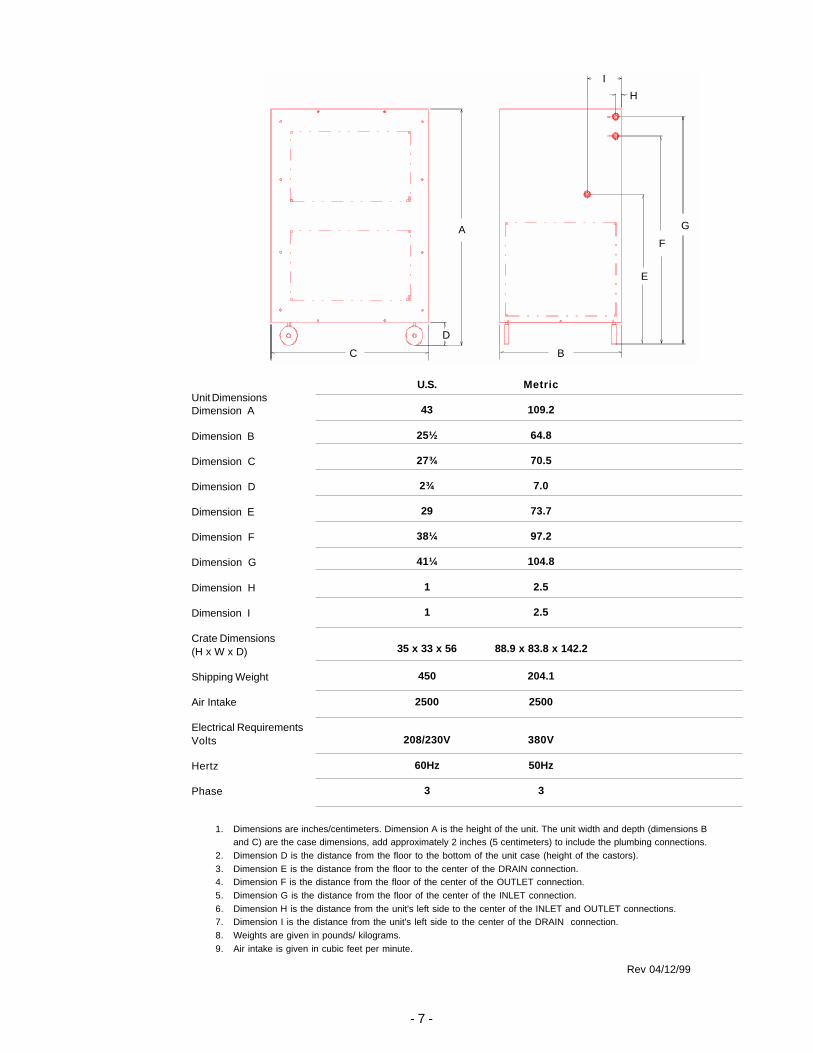
Unit DimensionsDimension A
Dimension B
Dimension C
Dimension D
Dimension E
Dimension F
Dimension G
Dimension H
Dimension I
Crate Dimensions(H x W x D)
Shipping Weight
Air Intake
Electrical RequirementsVolts
Hertz
Phase
Rev 04/12/99
U.S. Metric
43 109.2
25½ 64.8
27¾ 70.5
2¾ 7.0
29 73.7
38¼ 97.2
41¼ 104.8
1 2.5
1 2.5
35 x 33 x 56 88.9 x 83.8 x 142.2
450 204.1
2500 2500
208/230V 380V
60Hz 50Hz
3 3
1. Dimensions are inches/centimeters. Dimension A is the height of the unit. The unit width and depth (dimensions Band C) are the case dimensions, add approximately 2 inches (5 centimeters) to include the plumbing connections.
2. Dimension D is the distance from the floor to the bottom of the unit case (height of the castors).3. Dimension E is the distance from the floor to the center of the DRAIN connection.4. Dimension F is the distance from the floor of the center of the OUTLET connection.5. Dimension G is the distance from the floor of the center of the INLET connection.6. Dimension H is the distance from the unit's left side to the center of the INLET and OUTLET connections.7. Dimension I is the distance from the unit's left side to the center of the DRAIN connection.8. Weights are given in pounds/ kilograms.9. Air intake is given in cubic feet per minute.
- 8 -
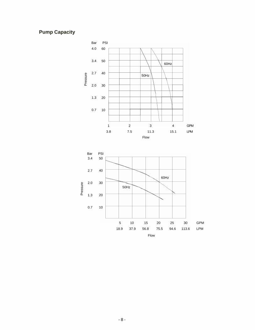
4.0
3.4
2.7
2.0
1.3
0.7
P
ress
ure
60
50
40
30
20
10
Bar PSI
1 2 3 4 GPM
3.8 7.5 11.3 15.1 LPM
Flow
Pump Capacity
3.4
2.7
2.0
1.3
0.7
P
ress
ure
50
40
30
20
10
Bar PSI
Flow
5 10 15 20 25 30 GPM
18.9 37.9 56.8 75.5 94.6 113.6 LPM
60Hz
50Hz
60Hz
50Hz

- 9 -
Section III Installation
SiteThe unit should be located in a laboratory or clean industrial environmentwhere ambient temperatures are inside the range of +13°C to +35°C, andmaximum humidity is below 80%.
Never place the unit in a location where excessive heat, moisture, orcorrosive materials are present.
The unit has an air-cooled refrigeration system. Air is drawn through thefront of the unit and discharged through rear and side panels. The unit mustbe positioned so the intake and discharge are not impeded. A minimumclearance of 18 inches (45 centimeters) on all vented sides is necessary foradequate ventilation. Inadequate ventilation will cause a reduction in coolingcapacity and, in extreme cases, compressor failure.
Excessively dusty areas should be avoided and a periodic cleaning scheduleshould be instituted (see Section V, Cleaning).
The unit will retain its full rated capacity in altitudes up to 6500 feet (2000meters), and ambient temperatures up to approximately +24°C. Above+24°C, reduce the cooling capacity 1% for every 0.5°C above +24°C, up to amaximum ambient temperature of +35°C.
Direction of Air Flow

- 10 -
ElectricalRequirements
The unit construction provides extra protection against the risk ofelectrical shock by grounding appropriate metal parts. The extra protec-tion may not function unless the power cord is connected to aproperly grounded outlet. It is the user's responsibility to assure aproper ground connection is provided.
Refer to Section II, Specifications, and to the serial number label on the rear ofthe unit for the specific electrical requirements of your unit. Ensure the voltageof the power source meets the specified voltage, ±10%. Transient overvoltagesmust comply with OVERVOLTAGE CATEGORY II. For mains supply, theminimum and normal category is II.
Units are also equipped with a compressor crankcase heater. The crankcaseheater warms the oil in the compressor and prevents refrigerant from mixingwith the oil. Before start up, the unit must be connected to its power source forat least 12 hours. This allows time for the oil to be heated and separate fromthe refrigerant.
50 Hertz units are supplied with a junction box located behing the controllerpanel. Wire the power connections in accordance to local, state and federalelectrical codes. For 380-415V 3 Phase 5 Wire units refer to Appendix C foradditional information. Double check all wiring to make sure it is properlyconnected and protected from the elements.
For 50 Hertz units which are not supplied with line cords we recommend aharmonized (HAR) grounded 3-conductor cord, type H05V V - F with conduc-tors of nominal 1.0mm2 cross section, rated 10 amps or a 5-conductor cord,type H07RN-F rated 20 amps, for the 5-wire units. A suitable cord end isrequired for connecting to the equipment (IEC 320/C13) and should terminatewith an IEC approved plug for proper connection to branch circuit. Cusomerprovided circuit protection is suggested. Make sure the voltage of the power sourcemeets the specified voltage, ±10%.
PlumbingRequirements
Before installing the unit to an instrument that previously used tap water as acooling fluid, flush the instrument several times to remove any rust or scale thathas built up. The manufacturer of the instrument should be able to recommenda cleaning fluid for their equipment.
The plumbing connections are located on the rear of the unit and are labelledINLET and OUTLET. Connections are ¾ inch FPT.
Remove the plastic protective plugs from both plumbing connections. Connectthe INLET fitting to the outlet of your application. Connect the OUTLET fitting tothe inlet of your application .
Never connect the fittings to your building water supply or any waterpressure source.

- 11 -
Flexible tubing, if used, should be of heavy wall or reinforced construction. Alltubing should be rated to withstand 80 psig at the highest operating tempera-tures. Make sure all tubing connections are securely clamped. Avoid runningtubing near radiators, hot water pipes, etc. If substantial lengths of tubing arenecessary, insulation may be required to prevent loss of cooling capacity.
Tubing and insulation are available from Thermo NESLAB. Contact our SalesDepartment for more information (see Preface, After-sale Support).
Keep the distance between the unit and your application as short as possible,and use the largest diameter tubing practical. Tubing should be straight andwithout bends. If diameter reductions must be made, make them at the inletand outlet of the instrument being cooled, not at the CFT.
If substantial lengths of cooling lines are required, pre-filled them with coolingfluid before connecting them to the unit.
FluidsNever use flammable or corrosive fluids with this unit. Do not useautomotive anti-freeze. Commercial anti-freeze contains silicates thatcan damage the pump seals. Use of automotive anti-freeze will void themanufacturer’s warranty.
Thermo NESLAB recommends using distilled/deionized water with a 0.05 to0.1 megohm-cm reading.
Highly distilled/deionized water, above the 3 megohm-cm region, maybecome aggressive and is not recommended for use with units withwetted parts other than stainless steel. Distilled/deionized water in the15 megohm-cm region is definitely aggressive and should not be used.Units operating in these regions should be closely monitored. SeeWater Quality Standards and Recommendations in Appendix A.
If you do not have access to distilled/deionized water we recommend usingfiltered tap water. Thermo NESLAB cannot recommend any custom fluids,these fluids are too dependent on your particular application.
Below +8°C, a non-freezing solution is required. The selected cooling fluidmust have a viscosity of 50 centistokes or less. A 50/50 mixture, by volume,of distilled/deionized water and laboratory grade ethylene glycol is suggested.
For units with extended temperature ranges above +35°C, we recommenddistilled/deionized water up to +80°C. Above +80°C, you are responsible for thefluid(s) used.

- 12 -
Filling RequirementsRemove the reservoir access panel by unscrewing the thumbscrews. Locatethe reservoir plug (square nut). Remove the plug and fill the reservoir withclean cooling fluid, following the special considerations outlined in thefollowing paragraphs.
Circulating to a closed system (closed to the atmosphere)Fill the reservoir to the bottom of the fill hole threads. Since the reservoircapacity is small compared to many instruments being cooled, have extracooling fluid on hand to keep the system topped off when external circulationis started.
NOTE: The tank in your unit has a vent which relieves pressure built up fromthermal expansion of water. The vent is located on the reservoir plug. Itactivates when tank pressure reaches 3 - 5 psi.
Do not replace reservoir plug with an non-vented type or damage to thetank may occur.
Circulating to an open system (open to the atmosphere)Fill the reservoir so ¾ of the fill hole threads are covered. Wrap the tankplug with Teflon® sealing tape. Replace the tank plug and tighten securely toprevent air entry.
When circulating cooling fluid to an open vessel or tank, connect the OUT-LET/SUPPLY and INLET/RETURN lines to the open tank. Secure the INLET/RETURN (suction) line below the fluid surface. The INLET/RETURN lineshould be submerged deep enough to avoid sucking air. Make sure theINLET/RETURN line is free of particles and debris that can block the flow offluid. A baffle or screen may be required.
Reservoir filling locations
Thumbscrew
Reservoir Access PanelReservoir Plug

- 13 -
Section IV Operation
Start UpBefore starting the unit, double check all electrical and plumbing connectionsand make sure the circulating system (the CFT, the instrument being cooled,and the tubing that connects them) has been properly filled with cooling fluid.On units with a circuit breaker located on the rear of the unit, ensure it is theon position. To start the unit, place the POWER Switch to the on ( I ) position.The refrigeration system and the recirculation pump will start. The POWERSwitch illuminates to indicate the system is operating. Units with PD pumpsdisplay the pump operating pressure on the RECIRCULATING PRESSUREgauge.
To turn the unit off, place the POWER Switch to the off ( 0 ) position.
COOL indicates the status of the refrigeration system. It illuminates to indicatethe refrigeration system is removing heat from the cooling fluid. As the operat-ing temperature approaches the temperature setpoint, the LED will flash. IDLEindicates the unit is in a hot-gas-bypass mode of operation. As the operatingtemperature approaches the temperature setpoint, the LED extinguishes.
When the unit is shut off, wait approximately five minutes before restarting.This allows time for the refrigeration pressures to equalize. If the pressuresare not allowed to equalize, the compressor will short-cycle (clicking sound)and no cooling will occur.
Digital Temperature Controller
C O O L
ID LE
Y ES N O
NESLAB Instruments
N E X TE N TE R
°C

- 14 -
Digital Controller
The digital controller controls temperature using a PID (Proportional-Integral-Derivative) algorithm. It is designed with self-diagnostic features and easy touse operator interface.
NEXT ENTERUse this key to accept and save changes.
YES, This key is used to increase numerical values.
NO, This key is used to decrease numerical values.
When the controller is powered it displays the reservoir fluid temperature.Press the NEXT ENTER key to view the setpoint. The display flashs betweenSP and the actual setpoint number. If desired, use the YES and NO keys tochange the setpoint. The display flashes as soon as either key is depressed.Once the desired setpoint is displayed, press the NEXT ENTER key.
NOTE: The new value will not be used by the controller until the NEXTENTER key is depressed and the display stops flashing. The controller willnot allow you to enter a value above the maximum or below the minimumvalue, or any illegal value. If you try to enter an illegal value the display willrevert to its original value when the last digit was entered.
If the NEXT ENTER key is not depressed within one minute, the controller willtime out and the new value will not be accepted. The controller will revert tothe previous value.
NOTE: Error codes are addressed in Section V, Maintenance and Service.
Digital Temperature Controller
C O O L
ID LE
Y ES N O
NESLAB Instruments
N E X TE N TE R
°C

- 15 -
Temperature LimitsThe controller is used to set the high and low temperature limits. If a limit isexceeded the controller will display an error code, see Section V.
With the controller displaying the reservoir fluid temperature, press and holdthe NO key and then press the NEXT ENTER key. The controller will displayTUNE. Press the YES key to display COOL. Press the NO key to displayeither HEAT or HIT, for high temperature limit. (HEAT is only displayed on unitswith an optional heater, press NO to display HIT.)
To change the HIT value press YES. The display will flash HIT and the actualvalue. Use the YES and NO keys to change the value. Once the desired valueis displayed press the NEXT ENTER key twice. The display will indicate LOTfor low temperature limit. Use the same procedure to change the low tempera-ture limit. The display will indicate STOR. Press YES to accept the changes,press NO to restore the previous values. The controller will again display thereservoir fluid temperature.
Pressure Relief ValveUnits with PD pumps have a pressure relief valve which establishes themaximum operating pressure of the unit. If the pressure of the fluid leaving thepump exceeds the valve setting, the relief valve will bypass the fluid within theunit to relieve the pressure. The relief valve does not determine the actualoperating pressure; the operating pressure is determined by the back pressureof the system.
If an adjustment is necessary, contact our Customer Service Department.
High/LowPressure Cutouts
Units are equipped with refrigeration High PressureCutouts (HPC) and Low Pressure Cutouts (LPC).Should either cutout activate the unit will shutdown.
The HPC activates if there is a blockage in therefrigeration lines or if the refrigerant temperaturebecomes too hot. The HPC is factory preset at400 psi.
The LPC activates if there is a leak in the refrigera-tion lines. THE LPC is factory preset at 4 psi.
The cutouts are located inside the case behind the rear panel. Once the causeof the shut down has been determined and corrected, manually depress thewhite button on the applicable cutout. If a "click" is not heard when depressingthe button, the cutout was not activated and the unit shut down for anotherreason.
HPC/LPC (Typical)
Reset

- 16 -
High TemperatureCutout (Optional)
The High Temperature Cutout (HTC) is designed to shut down the unit in theevent the temperature of the fluid in the reservoir exceeds the HTC setting. TheHTC is normally located on the rear of the unit.
NOTE: The HTC temperature scale is in °F.
Heater Package(Optional)
Heaters are controlled by a switch on the temperature controller. The heateritself is accessible through the small service panel on the rear of the unit.
The controller will indicate a low level display if the fluid level in the reservoirdrops below proper operating level.
Illustration A shows the desired fluid level for normal operation.
Should the reservoir be filled as shown in illustration B, units designed tooperate at high-end temperatures (near boiling) may cause air in the reservoirto become trapped. The air can be vented by slightly tilting the unit forward onits front castors.
Any fluid venting from the reservoir will drain through a hose which feeds to asmall hole in the bottom of the unit.
Do not used silicon-based fluids with units designed to operate at hightemperatures. These type fluids will damage the hoses and pump seal.
Fluid Level Fluid Level
Illustration A Illustration B
- 17 -
External PressureReducer (Optional)
For applications requiring a maximum pressure less than 55 PSI (380 kPa), anExternal Pressure Reducer (EPR) is available. An EPR allows an adjustableoperating pressure of 10 to 50 PSI (70 to 345 kPa). If the pressure of the fluidleaving the chiller exceeds the relief valve setting, the relief valve will bypassexcess fluid back into the chiller to relieve the overpressure.
The pressure of the system is deter-mined by the back pressure of theconnected equipment and the flow rateof the recirculating fluid to yourapplication. Connect the EPR asdescribed.
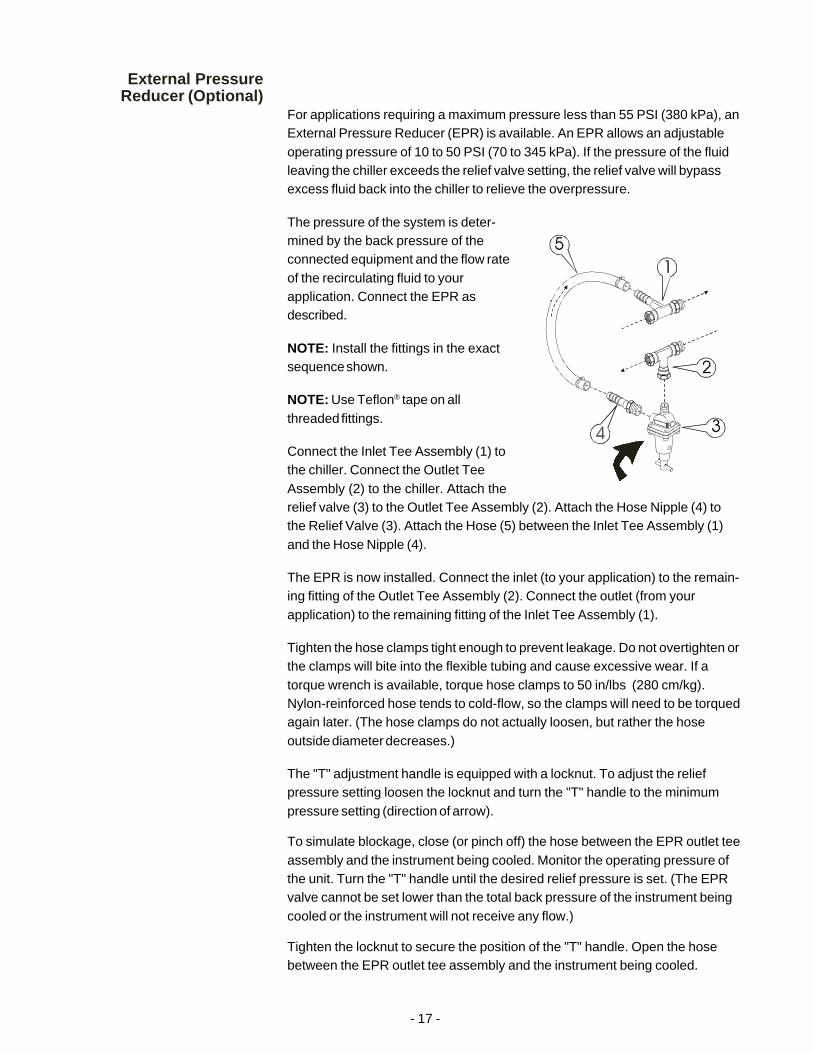
NOTE: Install the fittings in the exactsequence shown.
NOTE: Use Teflon® tape on allthreaded fittings.
Connect the Inlet Tee Assembly (1) tothe chiller. Connect the Outlet TeeAssembly (2) to the chiller. Attach therelief valve (3) to the Outlet Tee Assembly (2). Attach the Hose Nipple (4) tothe Relief Valve (3). Attach the Hose (5) between the Inlet Tee Assembly (1)and the Hose Nipple (4).
The EPR is now installed. Connect the inlet (to your application) to the remain-ing fitting of the Outlet Tee Assembly (2). Connect the outlet (from yourapplication) to the remaining fitting of the Inlet Tee Assembly (1).
Tighten the hose clamps tight enough to prevent leakage. Do not overtighten orthe clamps will bite into the flexible tubing and cause excessive wear. If atorque wrench is available, torque hose clamps to 50 in/lbs (280 cm/kg).Nylon-reinforced hose tends to cold-flow, so the clamps will need to be torquedagain later. (The hose clamps do not actually loosen, but rather the hoseoutside diameter decreases.)
The "T" adjustment handle is equipped with a locknut. To adjust the reliefpressure setting loosen the locknut and turn the "T" handle to the minimumpressure setting (direction of arrow).
To simulate blockage, close (or pinch off) the hose between the EPR outlet teeassembly and the instrument being cooled. Monitor the operating pressure ofthe unit. Turn the "T" handle until the desired relief pressure is set. (The EPRvalve cannot be set lower than the total back pressure of the instrument beingcooled or the instrument will not receive any flow.)
Tighten the locknut to secure the position of the "T" handle. Open the hosebetween the EPR outlet tee assembly and the instrument being cooled.

- 18 -
Section V Maintenance and Service
For personal safety and equipment reliability, the following procedureshould only be performed by a qualified technician. Contact ourService Department for assistance (see Preface, After-sale Support).
Service ContractsThermo NESLAB offers on-site Service Contracts that are designed to provideextended life and minimal down-time for your unit. For more information,contact our Service Department (see Preface, After-sale Support).
Draining theReservoir
Units are equipped with a ½ inch FPT DRAIN fitting located on the rear of theunit. To drain other CFT reservoirs we recommend the use of a wet/dryvacuum. Remove the reservoir plug and carefully insert the wet/dry vacuum soas not to damage the cooling coils. NOTE: Tilting the unit more than 45° mayallow compressor oil to seep into the suction line.
Do not blow high-pressure air into the system. Doing so may rupture thereservoir.
CleaningReservoirPeriodically inspect the fluid inside the reservoir. If cleaning is necessary,flush the reservoir with a cleaning fluid compatible with the circulating systemand the cooling fluid.
The cooling fluid should be replaced periodically. When operating at lowtemperatures, the concentration of water in the cooling fluid will increaseover time, leading to a loss of cooling capacity.
Before changing the cooling fluid, raise the operating temperature of the unitto de-ice the cooling coils. Refer to Section III, Filling Requirements forinstructions on replacing the cooling fluid.
CondenserFor proper operation, the unit needs to pull substantial amounts of airthrough a condenser. A build up of dust or debris on the fins of the condenserwill lead to a loss of cooling capacity.
The lower front of the unit has a one-piece grille assembly. Gently pry theassembly off with a flathead screwdriver. Use care not to scratch the paint.
Periodic vacuuming of the condenser fins is necessary. The frequency ofcleaning depends on the operating environment. We recommend a visualinspection of the condenser be made monthly after initial installation. Afterseveral months, the cleaning frequency will be established.
- 19 -
AlgaeTo restrict the growth of algae in the reservoir, it is recommended that thereservoir cover be kept in place and that all circulation lines be opaque. Thiswill eliminate the entrance of light which is required for the growth of mostcommon algae.
Thermo NESLAB recommends the use of Chloramine-T, 1 gram per 3.5 liters.Other algicides can be harmful to the unit's internal components. ContactNESLAB for additional information.
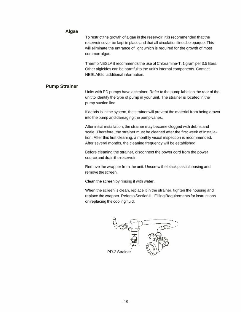
Pump StrainerUnits with PD pumps have a strainer. Refer to the pump label on the rear of theunit to identify the type of pump in your unit. The strainer is located in thepump suction line.
If debris is in the system, the strainer will prevent the material from being drawninto the pump and damaging the pump vanes.
After initial installation, the strainer may become clogged with debris andscale. Therefore, the strainer must be cleaned after the first week of installa-tion. After this first cleaning, a monthly visual inspection is recommended.After several months, the cleaning frequency will be established.
Before cleaning the strainer, disconnect the power cord from the powersource and drain the reservoir.
Remove the wrapper from the unit. Unscrew the black plastic housing andremove the screen.
Clean the screen by rinsing it with water.
When the screen is clean, replace it in the strainer, tighten the housing andreplace the wrapper. Refer to Section III, Filling Requirements for instructionson replacing the cooling fluid.
PD-2 Strainer
- 20 -
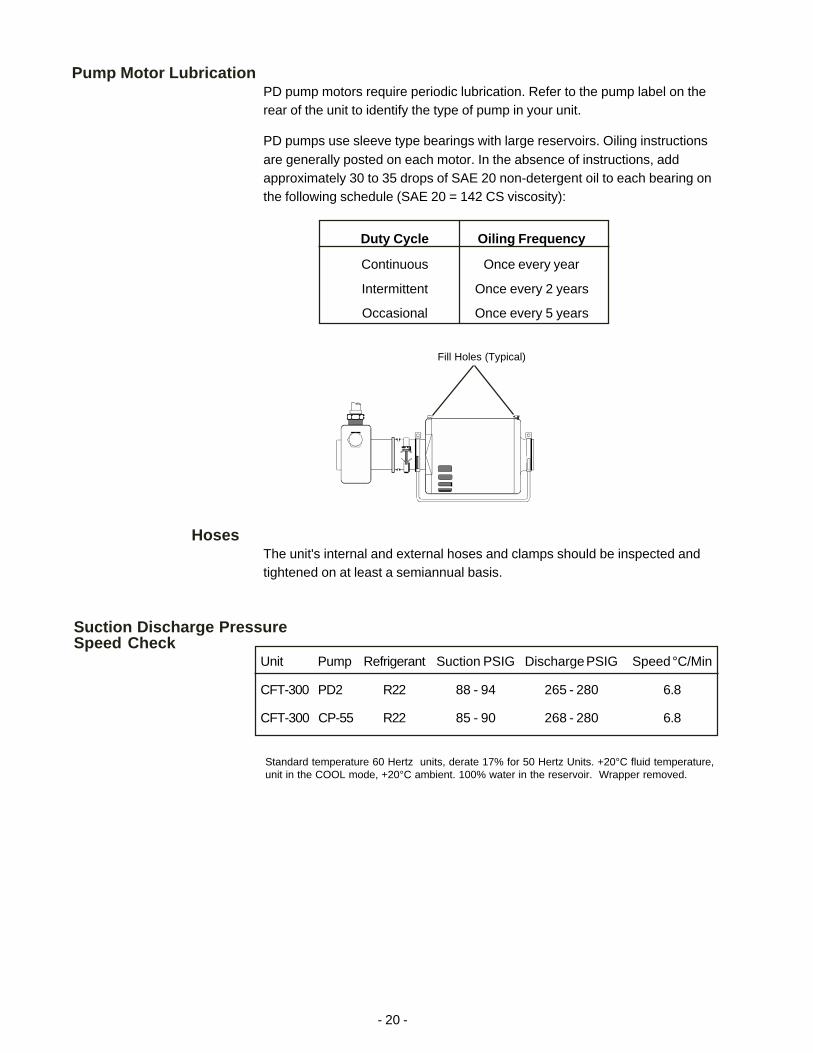
Duty Cycle Oiling Frequency
Continuous Once every year
Intermittent Once every 2 years
Occasional Once every 5 years
Fill Holes (Typical)
HosesThe unit's internal and external hoses and clamps should be inspected andtightened on at least a semiannual basis.
Suction Discharge PressureSpeed Check
Unit Pump Refrigerant Suction PSIG Discharge PSIG Speed °C/Min
CFT-300 PD2 R22 88 - 94 265 - 280 6.8
CFT-300 CP-55 R22 85 - 90 268 - 280 6.8
Standard temperature 60 Hertz units, derate 17% for 50 Hertz Units. +20°C fluid temperature,unit in the COOL mode, +20°C ambient. 100% water in the reservoir. Wrapper removed.
Pump Motor LubricationPD pump motors require periodic lubrication. Refer to the pump label on therear of the unit to identify the type of pump in your unit.
PD pumps use sleeve type bearings with large reservoirs. Oiling instructionsare generally posted on each motor. In the absence of instructions, addapproximately 30 to 35 drops of SAE 20 non-detergent oil to each bearing onthe following schedule (SAE 20 = 142 CS viscosity):

- 21 -
Error CodesThe controller also has the capability to display error codes. The codes are:
Display Indication
16 Bad calibration data
19 Temperature below low temperature setpoint
21 Temperature above high temperature setpoint
22 Excessive high temperature, unit requires immediate attention
23 Shorted RTD2
24 Open RTD2
25 Shorted RTD1
26 Open RTD1
ADD Reservoir fluid below normal operating level
The unit will continue to run with any of the above codes. If any other codeappears contact NESLAB customer service, see Preface.
NOTE: Depressing the NEXT ENTER key may clear error codes 01 through 04.Doing so restores the controller to factory-set default values.
Displaying Software Version
This procedure will display the software version number on the unit’s display. Inthe event the unit is not operational, the software version (and the checksum)can also be read from the label which is on the microprocessor chip itself.
The following chart uses an example of software version 000507.49b
begin in the reservoir temperature display 20.3C
Press and hold NO for at least 10 seconds. 0507
displays software version digits to left of decimal. Note the two leading zerosdo not display.
Press NEXT 49
displays software version digits to right of decimal.
Press NEXT 2
displays software version revision letter (as its equivalent number - displaycannot show letters. A=1, B=2, etc.)
Press NEXT 0000
displays checksum - this can be disregarded
Press NEXT 20.3C
returns to the temperature display

- 22 -
Section VI TroubleshootingChecklist
Unit will not startCheck the position of the optional circuit breaker the rear of the unit.
Check the line cord, make sure it is plugged in.
Check the voltage of the power source. Make sure it is within the ratedvoltage of the unit, ±10%.
Check that the Power Switch/Circuit Breaker has not tripped.
Check the setting on the High Temperature Cutout.
All units are equipped with high and low pressure switches. If either switchactivates the unit will shut down. Once the cause has been determined youhave to manually reset the switch. The switches are located behind the rearpanel. (See Section IV, Operation.)
Unit will not circulate fluidCheck the reservoir level. Fill, if necessary.
Make sure the pump has been purged.
Check the pressure gauge (units with PD pumps). If the reading is 60psig, check the instrument being cooled for restrictions in the cooling line.
Check the pump strainer (units with PD pumps). A clogged strainer canstarve the pump.
For 380-415V 3 Phase 5 Wire units, see Appendix B.
Inadequate temperature controlIf the temperature continues to rise, make sure the heat load of theinstrument being cooled does not exceed the rated specification. (SeeSection II, Specifications on page 6.)
Make sure the air intake and discharge are not impeded and the ambienttemperature does not exceed +35°C.
Make sure the condenser is free of dust and debris. (See Section V,Cleaning.)
If the compressor short-cycles (a clicking sound), check the line voltage.It should be within the 10% of the specified voltage. Wait 5 minutesbefore restarting the unit.
For 380-415V 3 Phase 5 Wire units, see Appendix B.
Service AssistanceIf, after following these troubleshooting steps, your unit fails to operateproperly, contact our Service Department for assistance (see Preface, After-sale Support). Before calling, please refer to the serial number label on therear of the unit to obtain the following information:
- unit BOM number- unit serial number- voltage of power source-software version

- 23 -
Appendix A Water Quality Standards and Recommendations
Permissible (PPM) Desirable (PPM)
Microbiologicals(algae, bacteria, fungi) 0 0
Inorganic Chemicals
Calcium <40 0.6
Chloride 250 <25
Copper 1.3 1.0
Iron 0.3 <0.1
Lead 0.015 0
Magnesium <12 0.1
Manganese 0.05 <0.03
Nitrates\Nitrites 10 as N 0
Potassium <20 0.3
Silicate 25 <1.0
Sodium <20 0.3
Sulfate 250 <50
Hardness 17 <0.05
Total Dissolved Solids 50 10
Other Parameters
pH 6.5-8.5 7-8
Resistivity 0.01* 0.05-0.1*
* Megohm-Cm (Compensated to 25°C)
Unfavorably high total ionized solids (TIS) canaccelerate the rate of galvanic corrosion. Thesecontaminants can function as electrolytes whichincrease the potential for galvanic cell corrosion andlead to localized corrosion such as pitting which canbe observed at the studs and on the outside surfaceof cooling coils. Eventually, the pitting will becomeso extensive that the coil will leak refrigerant into thewater reservoir.As an example, raw water in the United Statesaverages 171 ppm (of NaCl). The recommendedlevel for use in a water system is between 0.5 to 5.0ppm (of NaCl).Recommendation: Initially fill the tank with distilled/deionized water. Do not use untreated tap water asthe total ionized solids level may be too high.Maintain this water quality at a resistivity of between1 to 10 megohm-cm (compensated to 25°C) byusing a purification system. Although the initial fillmay be as high as 10 megohm-cm (compensated to25°C), the desired level for long time usage is 1 to 3megohm-cm (compensated to 25°C).The above two recommendations will reduce theelectrolytic potential of the water and prevent orreduce the galvanic corrosion observed.
Res
istiv
ity (
meg
ohm
-cm
@ 2
5°C
) Not Recommended, Increasingly Corrosive
Operations with Stainless Steel Systems
Operations withMixed MetalsCopper/Brass/Stainless Steel CONSULT MATERIALS ENGINEER
10 20 30 40 50 60 70 80
18.30
15.00
10.00
3.00
1.00
0.10
0.05
Water Quality Considerations
Temperature °C
- 32 -
Appendix C 380-415V 3 Phase 5 Wire Units
The unit is not equipped with a line cord. You are responsible for providing theproper electrical connections.
Run all power connections through the conduit located in the rear of the unitto the unit's power box.
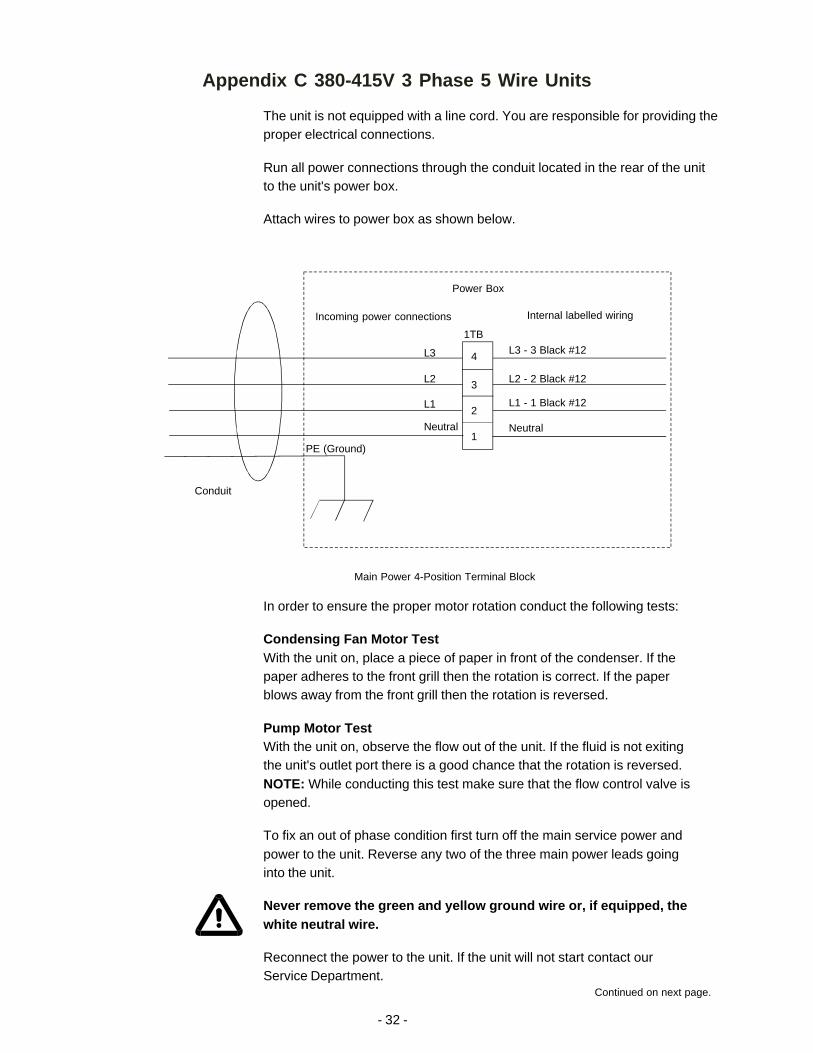
Attach wires to power box as shown below.
PE (Ground)
Conduit
Power Box
Internal labelled wiringIncoming power connections
1TB
Main Power 4-Position Terminal Block
L3
L2
L1
Neutral
L3 - 3 Black #12
L2 - 2 Black #12
L1 - 1 Black #12
Neutral
4
3
2
1
In order to ensure the proper motor rotation conduct the following tests:
Condensing Fan Motor TestWith the unit on, place a piece of paper in front of the condenser. If thepaper adheres to the front grill then the rotation is correct. If the paperblows away from the front grill then the rotation is reversed.
Pump Motor TestWith the unit on, observe the flow out of the unit. If the fluid is not exitingthe unit's outlet port there is a good chance that the rotation is reversed.NOTE: While conducting this test make sure that the flow control valve isopened.
To fix an out of phase condition first turn off the main service power andpower to the unit. Reverse any two of the three main power leads goinginto the unit.
Never remove the green and yellow ground wire or, if equipped, thewhite neutral wire.
Reconnect the power to the unit. If the unit will not start contact ourService Department.
Continued on next page.

- 33 -
FusesThree Class J fuses are used to protect the motor, in addition to a thermaloverload device. These fuses are located inside the main control panel. In theevent of an open fuse, investigate and correct the source of the overloadbefore replacing the fuse(s).
Always turn off the unit and disconnect the line cord from the powersource before attempting to do any service.
To replace the fuses, remove the two screws from the main control panel andthen open the panel door. For units equipped with a 380V, 3-Phase, CP-55pump, NESLAB part number 008596, replace the fuses with Class J, 600V,3A, TDLY fuses only. Do not replace the fuses with an alternate amperage.
Electrical RequirementsPermanently Connected Equipment must be connected to a branch circuitprotector of a rated value no less than the Maximum Overcurrent ProtectiveDevice (MOPD) which is on the nameplate. In addition there must be anappropriately rated and marked disconnect device within view of the unit.

WARRANTY
Thermo NESLAB Instruments, Inc. warrants for 12 months from date of shipment any Thermo NESLAB unitaccording to the following terms.
Any part of the unit manufactured or supplied by Thermo NESLAB and found in the reasonable judgment ofThermo NESLAB to be defective in material or workmanship will be repaired at an authorized Thermo NESLABRepair Depot without charge for parts or labor. The unit, including any defective part must be returned to anauthorized Thermo NESLAB Repair Depot within the warranty period. The expense of returning the unit to theauthorized Thermo NESLAB Repair Depot for warranty service will be paid for by the buyer. Thermo NESLAB’sresponsibility in respect to warranty claims is limited to performing the required repairs or replacements, and noclaim of breach of warranty shall be cause for cancellation or recision of the contract of sales of any unit.Withrespect to units that qualify for field service repairs, Thermo NESLAB’s responsibility is limited to the componentparts necessary for the repair and the labor that is required on site to perform the repair. Any travel labor ormileage charges are the financial responsibility of the buyer.
The buyer shall be responsible for any evaluation or warranty service call (including labor charges) if no defectsare found with the Thermo NESLAB product.
This warranty does not cover any unit that has been subject to misuse, neglect, or accident. This warranty doesnot apply to any damage to the unit that is the result of improper installation or maintenance, or to any unit thathas been operated or maintained in any way contrary to the operating or maintenance instructions specified inThermo NESLAB’s Instruction and Operation Manual. This warranty does not cover any unit that has beenaltered or modified so as to change its intended use.
In addition, this warranty does not extend to repairs made by the use of parts, accessories, or fluids which areeither incompatible with the unit or adversely affect its operation, performance, or durability.
Thermo NESLAB reserves the right to change or improve the design of any unit without assuming any obligationto modify any unit previously manufactured.
THE FOREGOING EXPRESS WARRANTY IS IN LIEU OF ALL OTHER WARRANTIES, EXPRESSED ORIMPLIED, INCLUDING BUT NOT LIMITED TO WARRANTIES OR MERCHANTABILITY AND FITNESS FOR APARTICULAR PURPOSE.
Thermo NESLAB’S OBLIGATION UNDER THIS WARRANTY IS STRICTLY AND EXCLUSIVELY LIMITED TOTHE REPAIR OR REPLACEMENT OF DEFECTIVE COMPONENT PARTS AND Thermo NESLAB DOES NOTASSUME OR AUTHORIZE ANYONE TO ASSUME FOR IT ANY OTHER OBLIGATION.
Thermo NESLAB ASSUMES NO RESPONSIBILITY FOR INCIDENTAL, CONSEQUENTIAL, OR OTHERDAMAGES INCLUDING, BUT NOT LIMITED TO LOSS OR DAMAGE TO PROPERTY, LOSS OF PROFITS ORREVENUE, LOSS OF THE UNIT, LOSS OF TIME, OR INCONVENIENCE.
This warranty applies to units sold in the United States. Any units sold elsewhere are warranted by the affiliatedmarketing company of Thermo NESLAB Instruments, Inc. This warranty and all matters arising pursuant to it shallbe governed by the law of the State of New Hampshire, United States. All legal actions brought in relation heretoshall be filed in the appropriate state or federal courts in New Hampshire, unless waived by Thermo NESLAB.